EP4311016A1 - Secondary battery having improved terminal structure - Google Patents
Secondary battery having improved terminal structure Download PDFInfo
- Publication number
- EP4311016A1 EP4311016A1 EP23753096.9A EP23753096A EP4311016A1 EP 4311016 A1 EP4311016 A1 EP 4311016A1 EP 23753096 A EP23753096 A EP 23753096A EP 4311016 A1 EP4311016 A1 EP 4311016A1
- Authority
- EP
- European Patent Office
- Prior art keywords
- terminal
- electrode terminal
- secondary battery
- negative electrode
- positive electrode
- Prior art date
- Legal status (The legal status is an assumption and is not a legal conclusion. Google has not performed a legal analysis and makes no representation as to the accuracy of the status listed.)
- Pending
Links
Images


Classifications
-
- H—ELECTRICITY
- H01—ELECTRIC ELEMENTS
- H01M—PROCESSES OR MEANS, e.g. BATTERIES, FOR THE DIRECT CONVERSION OF CHEMICAL ENERGY INTO ELECTRICAL ENERGY
- H01M50/00—Constructional details or processes of manufacture of the non-active parts of electrochemical cells other than fuel cells, e.g. hybrid cells
- H01M50/50—Current conducting connections for cells or batteries
- H01M50/572—Means for preventing undesired use or discharge
- H01M50/584—Means for preventing undesired use or discharge for preventing incorrect connections inside or outside the batteries
- H01M50/59—Means for preventing undesired use or discharge for preventing incorrect connections inside or outside the batteries characterised by the protection means
- H01M50/591—Covers
-
- H—ELECTRICITY
- H01—ELECTRIC ELEMENTS
- H01M—PROCESSES OR MEANS, e.g. BATTERIES, FOR THE DIRECT CONVERSION OF CHEMICAL ENERGY INTO ELECTRICAL ENERGY
- H01M50/00—Constructional details or processes of manufacture of the non-active parts of electrochemical cells other than fuel cells, e.g. hybrid cells
- H01M50/50—Current conducting connections for cells or batteries
- H01M50/543—Terminals
- H01M50/547—Terminals characterised by the disposition of the terminals on the cells
-
- H—ELECTRICITY
- H01—ELECTRIC ELEMENTS
- H01M—PROCESSES OR MEANS, e.g. BATTERIES, FOR THE DIRECT CONVERSION OF CHEMICAL ENERGY INTO ELECTRICAL ENERGY
- H01M50/00—Constructional details or processes of manufacture of the non-active parts of electrochemical cells other than fuel cells, e.g. hybrid cells
- H01M50/10—Primary casings; Jackets or wrappings
- H01M50/102—Primary casings; Jackets or wrappings characterised by their shape or physical structure
- H01M50/103—Primary casings; Jackets or wrappings characterised by their shape or physical structure prismatic or rectangular
-
- H—ELECTRICITY
- H01—ELECTRIC ELEMENTS
- H01M—PROCESSES OR MEANS, e.g. BATTERIES, FOR THE DIRECT CONVERSION OF CHEMICAL ENERGY INTO ELECTRICAL ENERGY
- H01M50/00—Constructional details or processes of manufacture of the non-active parts of electrochemical cells other than fuel cells, e.g. hybrid cells
- H01M50/10—Primary casings; Jackets or wrappings
- H01M50/147—Lids or covers
- H01M50/148—Lids or covers characterised by their shape
- H01M50/15—Lids or covers characterised by their shape for prismatic or rectangular cells
-
- H—ELECTRICITY
- H01—ELECTRIC ELEMENTS
- H01M—PROCESSES OR MEANS, e.g. BATTERIES, FOR THE DIRECT CONVERSION OF CHEMICAL ENERGY INTO ELECTRICAL ENERGY
- H01M50/00—Constructional details or processes of manufacture of the non-active parts of electrochemical cells other than fuel cells, e.g. hybrid cells
- H01M50/10—Primary casings; Jackets or wrappings
- H01M50/172—Arrangements of electric connectors penetrating the casing
- H01M50/174—Arrangements of electric connectors penetrating the casing adapted for the shape of the cells
- H01M50/176—Arrangements of electric connectors penetrating the casing adapted for the shape of the cells for prismatic or rectangular cells
-
- H—ELECTRICITY
- H01—ELECTRIC ELEMENTS
- H01M—PROCESSES OR MEANS, e.g. BATTERIES, FOR THE DIRECT CONVERSION OF CHEMICAL ENERGY INTO ELECTRICAL ENERGY
- H01M50/00—Constructional details or processes of manufacture of the non-active parts of electrochemical cells other than fuel cells, e.g. hybrid cells
- H01M50/30—Arrangements for facilitating escape of gases
- H01M50/342—Non-re-sealable arrangements
-
- H—ELECTRICITY
- H01—ELECTRIC ELEMENTS
- H01M—PROCESSES OR MEANS, e.g. BATTERIES, FOR THE DIRECT CONVERSION OF CHEMICAL ENERGY INTO ELECTRICAL ENERGY
- H01M50/00—Constructional details or processes of manufacture of the non-active parts of electrochemical cells other than fuel cells, e.g. hybrid cells
- H01M50/30—Arrangements for facilitating escape of gases
- H01M50/342—Non-re-sealable arrangements
- H01M50/3425—Non-re-sealable arrangements in the form of rupturable membranes or weakened parts, e.g. pierced with the aid of a sharp member
-
- H—ELECTRICITY
- H01—ELECTRIC ELEMENTS
- H01M—PROCESSES OR MEANS, e.g. BATTERIES, FOR THE DIRECT CONVERSION OF CHEMICAL ENERGY INTO ELECTRICAL ENERGY
- H01M50/00—Constructional details or processes of manufacture of the non-active parts of electrochemical cells other than fuel cells, e.g. hybrid cells
- H01M50/50—Current conducting connections for cells or batteries
- H01M50/543—Terminals
- H01M50/547—Terminals characterised by the disposition of the terminals on the cells
- H01M50/55—Terminals characterised by the disposition of the terminals on the cells on the same side of the cell
-
- H—ELECTRICITY
- H01—ELECTRIC ELEMENTS
- H01M—PROCESSES OR MEANS, e.g. BATTERIES, FOR THE DIRECT CONVERSION OF CHEMICAL ENERGY INTO ELECTRICAL ENERGY
- H01M50/00—Constructional details or processes of manufacture of the non-active parts of electrochemical cells other than fuel cells, e.g. hybrid cells
- H01M50/50—Current conducting connections for cells or batteries
- H01M50/543—Terminals
- H01M50/552—Terminals characterised by their shape
- H01M50/553—Terminals adapted for prismatic, pouch or rectangular cells
-
- H—ELECTRICITY
- H01—ELECTRIC ELEMENTS
- H01M—PROCESSES OR MEANS, e.g. BATTERIES, FOR THE DIRECT CONVERSION OF CHEMICAL ENERGY INTO ELECTRICAL ENERGY
- H01M50/00—Constructional details or processes of manufacture of the non-active parts of electrochemical cells other than fuel cells, e.g. hybrid cells
- H01M50/50—Current conducting connections for cells or batteries
- H01M50/543—Terminals
- H01M50/562—Terminals characterised by the material
-
- Y—GENERAL TAGGING OF NEW TECHNOLOGICAL DEVELOPMENTS; GENERAL TAGGING OF CROSS-SECTIONAL TECHNOLOGIES SPANNING OVER SEVERAL SECTIONS OF THE IPC; TECHNICAL SUBJECTS COVERED BY FORMER USPC CROSS-REFERENCE ART COLLECTIONS [XRACs] AND DIGESTS
- Y02—TECHNOLOGIES OR APPLICATIONS FOR MITIGATION OR ADAPTATION AGAINST CLIMATE CHANGE
- Y02E—REDUCTION OF GREENHOUSE GAS [GHG] EMISSIONS, RELATED TO ENERGY GENERATION, TRANSMISSION OR DISTRIBUTION
- Y02E60/00—Enabling technologies; Technologies with a potential or indirect contribution to GHG emissions mitigation
- Y02E60/10—Energy storage using batteries
Definitions
- the present invention relates to a secondary battery having a terminal structure that allows for an arrangement of a positive electrode terminal and/or a negative electrode terminal to be easily changed.
- Secondary batteries are rechargeable unlike primary batteries, and due to the possibility of compact size and high capacity, a lot of research on secondary batteries is being carried out. Due to developments in this technology, an increase in demand for mobile devices, and the emergence of electric vehicles and energy storage systems to address environmental concerns of the times, the demand for secondary batteries as energy sources is more rapidly increasing.
- Secondary batteries are classified into coin type batteries, cylindrical type batteries, prismatic type batteries, and pouch type batteries according to a shape of a battery case.
- an electrode assembly mounted in a battery case is a chargeable and dischargeable power generating device having a structure in which electrodes and a separator are stacked.
- An electrode assembly may be approximately classified into: a jelly-roll type electrode assembly, in which a separator is interposed between a positive electrode and a negative electrode, each of which is provided in the form of a sheet coated with an active material, and then, the positive electrode, the separator, and the negative electrode are wound; a stack type electrode assembly, in which a plurality of positive and negative electrodes with a separator interposed therebetween are sequentially stacked; and a stack/folding type electrode assembly, in which stack type unit cells are wound with a separation film having a long length.
- the prismatic secondary batteries have a positive electrode terminal and a negative electrode terminal disposed together on one surface, or one positive electrode terminal and one negative electrode terminal are each disposed on one of two surfaces facing each other.
- An arrangement of the positive and negative electrode terminals is determined by design specifications of various devices on which prismatic secondary batteries are mounted. Even in the same form factor, it is necessary to separately design the arrangement structure of the positive and negative electrode terminals for each design specification which can be time consuming and result in additional costs.
- Patent document 1 Korean Patent Publication No. 10-2019-0102816 (published on September 4, 2019 )
- the present invention is directed to providing a new prismatic secondary battery capable of easily changing an arrangement of a positive electrode terminal and a negative electrode terminal provided in a prismatic secondary battery without having to change the design of the prismatic secondary battery.
- the present invention relates to a secondary battery including: a positive electrode terminal and a negative electrode terminal disposed apart from each other on an upper surface of a battery case; and a terminal structure including a terminal body part and a terminal extension part, wherein the terminal structure covers at least one of the positive electrode terminal and the negative electrode terminal such that the respective positive electrode terminal or the negative electrode terminal is not exposed, wherein the terminal structure is coupled to an upper surface of the battery case and one or more side surfaces connected to the upper surface, and wherein the terminal extension part is electrically connected to the at least one of the positive electrode terminal and the negative electrode terminal, and is exposed at any one or more side surfaces of the terminal body part except the upper surface.
- the battery case may be a hexahedral battery case.
- the secondary battery of the present invention further includes an extension wire electrically connecting the terminal extension part to the positive electrode terminal or the negative electrode terminal, and the extension wire is covered by the terminal body part.
- the terminal body part is made of an insulating resin material, and the positive electrode terminal or the negative electrode terminal is not activated by the terminal body part.
- the terminal body part is coupled to the upper surface of the battery case and the one or more side surfaces connected to the upper surface of the battery case; and the terminal extension part is exposed at the one or more side surfaces connected to the upper surface.
- the terminal structure is connected to each of the positive electrode terminal and the negative electrode terminal.
- the terminal extension part of the terminal structure coupled to the positive electrode terminal is positioned on a first surface and the terminal extension part of the terminal structure coupled to the negative electrode terminal is positioned on a second surface.
- the first surface is different from the second surface.
- the first surface may be adjacent to the second surface, or the first surface may be opposite to the second surface.
- first surface and the second surface may be located on a common surface.
- the first surface may be separated from the second surface in a vertical direction on the common surface, or the first surface may be separated from the second surface in a horizontal direction on the common surface.
- the secondary battery of the present invention further includes a venting part on a surface of the battery case, wherein the terminal extension part may be positioned on a surface other than the surface comprising the venting part.
- the venting part may be positioned between the positive electrode terminal and the negative electrode terminal on the upper surface of the battery case.
- the terminal structure may be detachable from the battery case.
- an arrangement of a positive electrode terminal and/or a negative electrode terminal can be easily changed by coupling a terminal structure to an upper surface of the secondary battery, specifically to a corner of an upper surface of the secondary battery.
- a position of a terminal part can be freely controlled without changing an existing manufacturing process of the inside of a cell, thereby reducing the development and production costs of a prismatic secondary battery.
- a positive electrode terminal and a negative electrode terminal can be spaced apart from a venting part, thereby preventing damage when the venting part is broken and ensuring safety of the device without having to install a separate gas exhaust inductor or a barrier.
- the positions of the positive and negative electrode terminals disposed on a surface of the battery case, including the upper surface can be freely changed according to the needs of a user by applying the terminal structure to, and without changing the design of, the battery, thereby reducing production costs of the secondary battery.
- the secondary battery of the present invention includes: a positive electrode terminal and a negative electrode terminal disposed apart from each other on an upper surface of a battery case; and a terminal structure including a terminal body part and a terminal extension part, wherein the terminal structure covers at least one of the positive electrode terminal and the negative electrode terminal such that the respective positive electrode terminal or the negative electrode terminal is not exposed, wherein the terminal structure is coupled to the upper surface of the battery case and one or more side surfaces connected to the upper surface, and wherein the terminal extension part is electrically connected to the at least one of the positive electrode terminal and the negative electrode terminal, and is exposed at any one or more side surfaces of the terminal body part except the upper surface.
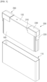
- FIG. 1 is a perspective view of a secondary battery 100 according to the present invention
- FIG. 2 is a perspective view of a coupling structure of the secondary battery 100 and a terminal structure 200 according to the present invention.
- the present invention relates to the secondary battery 100, and particularly, to a prismatic secondary battery 100 in which a positive electrode terminal 120 and a negative electrode terminal 130 are disposed apart from each other on an upper surface of a battery case 110 having a hexahedral shape.
- the prismatic secondary battery 100 shown in the drawings is merely an example, and a ratio of a length, a width, and a height thereof may vary.
- front and rear directions, and up, down, left, and right directions will be referred to with reference to the accompanying drawings.
- a surface on which the positive electrode terminal 120 and the negative electrode terminal 130 are disposed is referred to as an upper surface
- a surface facing the upper surface is referred to as a lower surface.
- the secondary battery 100 of the present invention includes the terminal structure 200.
- the terminal structure 200 is a hinge-like structure coupled to at least one corner of the upper surface of the battery case 110, and includes a terminal body part 210 and an terminal extension part 220.
- the terminal body part 210 refers to a body part of the terminal structure 200 that surrounds the positive electrode terminal 120 or the negative electrode terminal 130 such that the positive electrode terminal 120 or the negative electrode terminal 130, respectively, is not exposed, and is coupled to both the upper surface of the battery case 110 and one or more surfaces (side, or front and rear surfaces, etc.) connected to the upper surface.
- the terminal structure 200 may be coupled to only one of the positive electrode terminal 120 and the negative electrode terminal 130.
- the terminal extension part 220 is a connection terminal that is electrically connected to the positive electrode terminal 120 or the negative electrode terminal 130 and is exposed at any one surface of the terminal body part 210 excluding an upper surface thereof. That is, the terminal extension part 220 serves as a new positive electrode terminal 120 or negative electrode terminal 130 positioned on another surface other than the upper surface because the positive electrode terminal 120 or the negative electrode terminal 130 surrounded by the terminal body part 210 is not exposed.
- the positions of the positive electrode terminal 120 and the negative electrode terminal 130 disposed on the upper surface of the battery case 110 can be freely changed according to the needs of a user by applying the terminal structure 200 to the battery and without having to change the design of the battery. Accordingly, in the present invention, the positions of the positive electrode terminal 120 and the negative electrode terminal 130 can be easily changed using the terminal structure 200 for the prismatic secondary battery 100 having the same form factor, thereby reducing production costs of the secondary battery 100.
- the positive electrode terminal 120 or the negative electrode terminal 130 and the terminal extension part 220 are electrically connected through an extension wire 230, and the extension wire 230 is not exposed to the outside of the terminal body part 210. That is, the extension wire 230 is insulated from the outside.
- the extension wire 230 and the terminal extension part 220 may be embedded in the terminal body part 210 made of an insulating resin material through insert molding or the like. Thus, only the terminal extension part 220 is exposed to the outside, thereby preventing damage or short-circuit of the extension wire 230.
- the extension wire 230 and the terminal extension part 220 may be integrally formed or may be provided as separate parts to be coupled to the terminal body part 210.
- the terminal body part 210 is coupled to the upper surface of the battery case 110 and one side surface connected to the upper surface, and the terminal extension part 220 is exposed at the one side surface connected to the upper surface. Accordingly, the position of the positive electrode terminal 120 or the negative electrode terminal 130 positioned on the upper surface of the battery case 110 is moved to the side surface through the terminal extension part 220.
- the terminal structure 200 may be coupled to each of the positive electrode terminal 120 and the negative electrode terminal 130, and thus, each of the positive electrode terminal 120 and the negative electrode terminal 130 can be disposed on side surfaces facing each other. That is, each of the positive electrode terminal 120 and the negative electrode terminal 130 disposed together on the upper surface of the battery case 110 can be moved to an adjacent side surface, and thus, the initial prismatic secondary battery 100 designed as a unidirectional secondary battery 100 is changed into a bidirectional secondary battery 100.
- the vertical positions of the terminal extension parts 220 of the terminal structures 200 coupled to the positive electrode terminal 120 and the negative electrode terminal 130 may be different from each other. That is, the terminal extension parts 220 on left and right side surfaces may be designed to have bilateral asymmetry, and as described above, the terminal structure 200 can be applied to change an arrangement of the positive electrode terminal 120 and the negative electrode terminal 130 in many different ways in the secondary battery 100 of the present invention.
- the terminal structure 200 may be manufactured in various ways in which the terminal structure 200 is additionally attached to the completed secondary battery 100, or an electrode assembly 160 is attached to a cap plate 150 constituting the upper surface of the battery case 110, and then the terminal structure 200 coupled before the electrode assembly 160 is encapsulated in the battery case 110.
- electrode assembly 160 is described in the illustrated embodiment as being a stack-type assembly, the present invention is not limited thereto, and the illustrated embodiment may be applied to the prismatic secondary battery 100 that accommodates various types of electrode assemblies 160 such as a jelly-roll type electrode assembly.
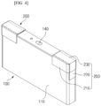
- FIG. 4 is a view of a secondary battery 100 according to another exemplary embodiment of the present invention.
- the second embodiment of FIG. 4 includes the same configuration as described above in the first embodiment, and also includes a venting part 140,
- the venting part 140 is a safety component of a battery, whereby when the internal pressure of the secondary battery 100 increases to a certain level or higher, the venting part 140 breaks to discharge gas and prevent explosion of the secondary battery 100.
- the venting part 140 may be formed through a method of forming a notch having a thickness that is less than the surrounding thickness in a surface of a battery case 110.
- the venting part 140 is positioned on an upper surface of the battery case 110 on which a positive electrode terminal 120 and a negative electrode terminal 130 are positioned, in particular, between the positive electrode terminal 120 and the negative electrode terminal 130.
- the venting part 140 is broken and internal gas is ejected, the positive electrode terminal 120 and the negative electrode terminal 130 are easily damaged by corrosion, ignition, and the like.
- the terminal structure 200 provided in the present invention allows the positive electrode terminal 120 and the negative electrode terminal 130 to be separated from the venting part 140 by being disposed on a different surface from the venting part 140, thereby also contributing to the prevention of damage to the electrode terminals due to gas ejection and flame propagation.
- the venting part 140 is provided on one surface, for example, an upper surface of the battery case 110, and a terminal extension part 220 of the terminal structure 200 is provided on a surface other than the surface, for example, a side surface on which the venting part 140 is provided. That is, the venting part 140 and the electrode terminals are physically separated by the terminal structure 200, thereby improving the safety of the secondary battery 100 and actively and quickly responding to various needs of a user.
- the present invention is suitable for rechargeable secondary batteries.
Landscapes
- Chemical & Material Sciences (AREA)
- Chemical Kinetics & Catalysis (AREA)
- Electrochemistry (AREA)
- General Chemical & Material Sciences (AREA)
- Connection Of Batteries Or Terminals (AREA)
- Gas Exhaust Devices For Batteries (AREA)
- Sealing Battery Cases Or Jackets (AREA)
Abstract
Description
- The present invention relates to a secondary battery having a terminal structure that allows for an arrangement of a positive electrode terminal and/or a negative electrode terminal to be easily changed.
- This application claims the benefit of priority based on
Korean Patent Application No. 10-2022-0017171 filed on February 09, 2022 - Secondary batteries are rechargeable unlike primary batteries, and due to the possibility of compact size and high capacity, a lot of research on secondary batteries is being carried out. Due to developments in this technology, an increase in demand for mobile devices, and the emergence of electric vehicles and energy storage systems to address environmental concerns of the times, the demand for secondary batteries as energy sources is more rapidly increasing.
- Secondary batteries are classified into coin type batteries, cylindrical type batteries, prismatic type batteries, and pouch type batteries according to a shape of a battery case. In such a secondary battery, an electrode assembly mounted in a battery case is a chargeable and dischargeable power generating device having a structure in which electrodes and a separator are stacked.
- An electrode assembly may be approximately classified into: a jelly-roll type electrode assembly, in which a separator is interposed between a positive electrode and a negative electrode, each of which is provided in the form of a sheet coated with an active material, and then, the positive electrode, the separator, and the negative electrode are wound; a stack type electrode assembly, in which a plurality of positive and negative electrodes with a separator interposed therebetween are sequentially stacked; and a stack/folding type electrode assembly, in which stack type unit cells are wound with a separation film having a long length.
- Among the various types of secondary batteries, many of the prismatic secondary batteries have a positive electrode terminal and a negative electrode terminal disposed together on one surface, or one positive electrode terminal and one negative electrode terminal are each disposed on one of two surfaces facing each other. An arrangement of the positive and negative electrode terminals is determined by design specifications of various devices on which prismatic secondary batteries are mounted. Even in the same form factor, it is necessary to separately design the arrangement structure of the positive and negative electrode terminals for each design specification which can be time consuming and result in additional costs.
- (Patent document 1)
Korean Patent Publication No. 10-2019-0102816 (published on September 4, 2019 - The present invention is directed to providing a new prismatic secondary battery capable of easily changing an arrangement of a positive electrode terminal and a negative electrode terminal provided in a prismatic secondary battery without having to change the design of the prismatic secondary battery.
- The present invention relates to a secondary battery including: a positive electrode terminal and a negative electrode terminal disposed apart from each other on an upper surface of a battery case; and a terminal structure including a terminal body part and a terminal extension part, wherein the terminal structure covers at least one of the positive electrode terminal and the negative electrode terminal such that the respective positive electrode terminal or the negative electrode terminal is not exposed, wherein the terminal structure is coupled to an upper surface of the battery case and one or more side surfaces connected to the upper surface, and wherein the terminal extension part is electrically connected to the at least one of the positive electrode terminal and the negative electrode terminal, and is exposed at any one or more side surfaces of the terminal body part except the upper surface.
- In one exemplary embodiment, the battery case may be a hexahedral battery case.
- In addition, the secondary battery of the present invention further includes an extension wire electrically connecting the terminal extension part to the positive electrode terminal or the negative electrode terminal, and the extension wire is covered by the terminal body part.
- For example, the terminal body part is made of an insulating resin material, and the positive electrode terminal or the negative electrode terminal is not activated by the terminal body part.
- In an exemplary embodiment, the terminal body part is coupled to the upper surface of the battery case and the one or more side surfaces connected to the upper surface of the battery case; and the terminal extension part is exposed at the one or more side surfaces connected to the upper surface.
- Here, the terminal structure is connected to each of the positive electrode terminal and the negative electrode terminal.
- Accordingly, the terminal extension part of the terminal structure coupled to the positive electrode terminal is positioned on a first surface and the terminal extension part of the terminal structure coupled to the negative electrode terminal is positioned on a second surface.
- In an exemplary embodiment, the first surface is different from the second surface.
- For example, the first surface may be adjacent to the second surface, or the first surface may be opposite to the second surface.
- In another exemplary embodiment, the first surface and the second surface may be located on a common surface.
- For example, the first surface may be separated from the second surface in a vertical direction on the common surface, or the first surface may be separated from the second surface in a horizontal direction on the common surface.
- Meanwhile, the secondary battery of the present invention further includes a venting part on a surface of the battery case, wherein the terminal extension part may be positioned on a surface other than the surface comprising the venting part.
- For example, the venting part may be positioned between the positive electrode terminal and the negative electrode terminal on the upper surface of the battery case.
- In addition, in the secondary battery of the present invention, the terminal structure may be detachable from the battery case.
- In a secondary battery having the above configuration, an arrangement of a positive electrode terminal and/or a negative electrode terminal can be easily changed by coupling a terminal structure to an upper surface of the secondary battery, specifically to a corner of an upper surface of the secondary battery. Thereby, a position of a terminal part can be freely controlled without changing an existing manufacturing process of the inside of a cell, thereby reducing the development and production costs of a prismatic secondary battery.
- In addition, because a position of a terminal part can be freely controlled, a degree of freedom can be provided to the module/pack manufacturing process.
- Also, when a venting part is disposed on the same surface as a surface on which positive and negative electrode terminals are disposed, the positive and negative electrode terminals as well as surrounding secondary batteries and electric devices are damaged by a gas or flame that is ejected when the venting part is broken. In a secondary battery that uses the terminal structure of the present invention, a positive electrode terminal and a negative electrode terminal can be spaced apart from a venting part, thereby preventing damage when the venting part is broken and ensuring safety of the device without having to install a separate gas exhaust inductor or a barrier.
- However, the technical effects obtainable through the present invention are not limited to the above-described effects, and other effects that are not described herein will be clearly understood by those skilled in the art from the following descriptions of the present invention.
- The accompanying drawings illustrate exemplary embodiments of the present invention and, together with the following detailed description, serve to provide further understanding of the technical spirit of the present invention. However, the present invention is not to be construed as being limited to the drawings.
-
FIG. 1 is a perspective view of a secondary battery according to the present invention. -
FIG. 2 is a perspective view of a coupling structure of the secondary battery and a terminal structure according to the present invention. -
FIG. 3 is a view of an exemplary embodiment for a secondary battery of the present invention. -
FIG. 4 is a view of another exemplary embodiment for a secondary battery of the present invention. - While the present invention may be variously changed and have various embodiments, specific embodiments will be described in detail below.
- However, it is to be understood that the present invention is not limited to the specific embodiments described herein but includes all modifications, equivalents, and substitutions included in the spirit and the scope of the present invention.
- In this application, it should be understood that terms such as "include" or "have" are intended to indicate the presence of a feature, number, step, operation, component, part, or a combination thereof described on the specification, and they do not preclude the possibility of the presence or addition of one or more other features or numbers, steps, operations, components, parts or combinations thereof.
- In addition, in this application, when a portion such as a layer, a film, an area, a plate, and the like are referred to as being "on" another portion, this includes not only the case where the portion is "directly on" another portion but also the case where still another portion is interposed therebetween. On the other hand, when a portion such as a layer, a film, an area, a plate, and the like are referred to as being "under" another portion, this includes not only the case where the portion is "directly under" another portion but also the case where still another portion is interposed therebetween. In addition, to be disposed "on" in the present application may include the case of being disposed at the bottom as well as the top.
- As described herein, in the secondary battery including the terminal structure of the present invention, the positions of the positive and negative electrode terminals disposed on a surface of the battery case, including the upper surface, can be freely changed according to the needs of a user by applying the terminal structure to, and without changing the design of, the battery, thereby reducing production costs of the secondary battery.
- The secondary battery of the present invention includes: a positive electrode terminal and a negative electrode terminal disposed apart from each other on an upper surface of a battery case; and a terminal structure including a terminal body part and a terminal extension part, wherein the terminal structure covers at least one of the positive electrode terminal and the negative electrode terminal such that the respective positive electrode terminal or the negative electrode terminal is not exposed, wherein the terminal structure is coupled to the upper surface of the battery case and one or more side surfaces connected to the upper surface, and wherein the terminal extension part is electrically connected to the at least one of the positive electrode terminal and the negative electrode terminal, and is exposed at any one or more side surfaces of the terminal body part except the upper surface.
- Hereinafter, specific embodiments of a secondary battery of the present invention will be described with reference to the accompanying drawings.
-
FIG. 1 is a perspective view of asecondary battery 100 according to the present invention, andFIG. 2 is a perspective view of a coupling structure of thesecondary battery 100 and aterminal structure 200 according to the present invention. - As illustrated in
FIGS. 1 and2 , the present invention relates to thesecondary battery 100, and particularly, to a prismaticsecondary battery 100 in which apositive electrode terminal 120 and anegative electrode terminal 130 are disposed apart from each other on an upper surface of abattery case 110 having a hexahedral shape. Here, the prismaticsecondary battery 100 shown in the drawings is merely an example, and a ratio of a length, a width, and a height thereof may vary. However, for convenience of description, front and rear directions, and up, down, left, and right directions will be referred to with reference to the accompanying drawings. For example, a surface on which thepositive electrode terminal 120 and thenegative electrode terminal 130 are disposed is referred to as an upper surface, and a surface facing the upper surface is referred to as a lower surface. - The
secondary battery 100 of the present invention includes theterminal structure 200. Theterminal structure 200 is a hinge-like structure coupled to at least one corner of the upper surface of thebattery case 110, and includes aterminal body part 210 and anterminal extension part 220. - The
terminal body part 210 refers to a body part of theterminal structure 200 that surrounds thepositive electrode terminal 120 or thenegative electrode terminal 130 such that thepositive electrode terminal 120 or thenegative electrode terminal 130, respectively, is not exposed, and is coupled to both the upper surface of thebattery case 110 and one or more surfaces (side, or front and rear surfaces, etc.) connected to the upper surface. Although the drawings illustrate an example in which theterminal structure 200 is coupled to each of thepositive electrode terminal 120 and thenegative electrode terminal 130, according to embodiments, theterminal structure 200 may be coupled to only one of thepositive electrode terminal 120 and thenegative electrode terminal 130. - The
terminal extension part 220 is a connection terminal that is electrically connected to thepositive electrode terminal 120 or thenegative electrode terminal 130 and is exposed at any one surface of theterminal body part 210 excluding an upper surface thereof. That is, theterminal extension part 220 serves as a newpositive electrode terminal 120 ornegative electrode terminal 130 positioned on another surface other than the upper surface because thepositive electrode terminal 120 or thenegative electrode terminal 130 surrounded by theterminal body part 210 is not exposed. - As described above, in the
secondary battery 100 of the present invention including theterminal structure 200, the positions of thepositive electrode terminal 120 and thenegative electrode terminal 130 disposed on the upper surface of thebattery case 110 can be freely changed according to the needs of a user by applying theterminal structure 200 to the battery and without having to change the design of the battery. Accordingly, in the present invention, the positions of thepositive electrode terminal 120 and thenegative electrode terminal 130 can be easily changed using theterminal structure 200 for the prismaticsecondary battery 100 having the same form factor, thereby reducing production costs of thesecondary battery 100. - In one embodiment of the present invention, the
positive electrode terminal 120 or thenegative electrode terminal 130 and theterminal extension part 220 are electrically connected through anextension wire 230, and theextension wire 230 is not exposed to the outside of theterminal body part 210. That is, theextension wire 230 is insulated from the outside. For example, theextension wire 230 and theterminal extension part 220 may be embedded in theterminal body part 210 made of an insulating resin material through insert molding or the like. Thus, only theterminal extension part 220 is exposed to the outside, thereby preventing damage or short-circuit of theextension wire 230. For reference, theextension wire 230 and theterminal extension part 220 may be integrally formed or may be provided as separate parts to be coupled to theterminal body part 210. - According to the illustrated embodiment, the
terminal body part 210 is coupled to the upper surface of thebattery case 110 and one side surface connected to the upper surface, and theterminal extension part 220 is exposed at the one side surface connected to the upper surface. Accordingly, the position of thepositive electrode terminal 120 or thenegative electrode terminal 130 positioned on the upper surface of thebattery case 110 is moved to the side surface through theterminal extension part 220. - In addition, the
terminal structure 200 may be coupled to each of thepositive electrode terminal 120 and thenegative electrode terminal 130, and thus, each of thepositive electrode terminal 120 and thenegative electrode terminal 130 can be disposed on side surfaces facing each other. That is, each of thepositive electrode terminal 120 and thenegative electrode terminal 130 disposed together on the upper surface of thebattery case 110 can be moved to an adjacent side surface, and thus, the initial prismaticsecondary battery 100 designed as a unidirectionalsecondary battery 100 is changed into a bidirectionalsecondary battery 100. - Meanwhile, although not shown, the vertical positions of the
terminal extension parts 220 of theterminal structures 200 coupled to thepositive electrode terminal 120 and thenegative electrode terminal 130 may be different from each other. That is, theterminal extension parts 220 on left and right side surfaces may be designed to have bilateral asymmetry, and as described above, theterminal structure 200 can be applied to change an arrangement of thepositive electrode terminal 120 and thenegative electrode terminal 130 in many different ways in thesecondary battery 100 of the present invention. - As illustrated in
FIGS. 2 and3 , theterminal structure 200 may be manufactured in various ways in which theterminal structure 200 is additionally attached to the completedsecondary battery 100, or anelectrode assembly 160 is attached to acap plate 150 constituting the upper surface of thebattery case 110, and then theterminal structure 200 coupled before theelectrode assembly 160 is encapsulated in thebattery case 110. - In addition, although the
electrode assembly 160 is described in the illustrated embodiment as being a stack-type assembly, the present invention is not limited thereto, and the illustrated embodiment may be applied to the prismaticsecondary battery 100 that accommodates various types ofelectrode assemblies 160 such as a jelly-roll type electrode assembly. -
FIG. 4 is a view of asecondary battery 100 according to another exemplary embodiment of the present invention. The second embodiment ofFIG. 4 includes the same configuration as described above in the first embodiment, and also includes a ventingpart 140,
The ventingpart 140 is a safety component of a battery, whereby when the internal pressure of thesecondary battery 100 increases to a certain level or higher, the ventingpart 140 breaks to discharge gas and prevent explosion of thesecondary battery 100. For example, the ventingpart 140 may be formed through a method of forming a notch having a thickness that is less than the surrounding thickness in a surface of abattery case 110. - In the
secondary battery 100 shown inFIG. 4 , the ventingpart 140 is positioned on an upper surface of thebattery case 110 on which apositive electrode terminal 120 and anegative electrode terminal 130 are positioned, in particular, between thepositive electrode terminal 120 and thenegative electrode terminal 130. In this case, when the ventingpart 140 is broken and internal gas is ejected, thepositive electrode terminal 120 and thenegative electrode terminal 130 are easily damaged by corrosion, ignition, and the like. - The
terminal structure 200 provided in the present invention allows thepositive electrode terminal 120 and thenegative electrode terminal 130 to be separated from the ventingpart 140 by being disposed on a different surface from the ventingpart 140, thereby also contributing to the prevention of damage to the electrode terminals due to gas ejection and flame propagation. - According to the illustrated embodiment, the venting
part 140 is provided on one surface, for example, an upper surface of thebattery case 110, and aterminal extension part 220 of theterminal structure 200 is provided on a surface other than the surface, for example, a side surface on which theventing part 140 is provided. That is, the ventingpart 140 and the electrode terminals are physically separated by theterminal structure 200, thereby improving the safety of thesecondary battery 100 and actively and quickly responding to various needs of a user. - In the above, the present invention has been described in more detail through the drawings and embodiments. However, the configurations described in the drawings or the embodiments in the specification are merely embodiments of the present invention and do not represent all the technical ideas of the present invention. Thus, it is to be understood that there may be various equivalents and variations in place of the drawings and embodiments described herein at the time of filing the present application.
-
- 100: secondary battery
- 110: battery case
- 120: positive electrode terminal
- 130: negative electrode terminal
- 140: venting part
- 150: cap plate
- 160: electrode assembly
- 200: terminal structure
- 210: terminal body part
- 220: terminal extension part
- 230: extension wire
- The present invention is suitable for rechargeable secondary batteries.
Claims (16)
- A secondary battery comprising:a positive electrode terminal and a negative electrode terminal disposed apart from each other on an upper surface of a battery case; anda terminal structure including a terminal body part and a terminal extension part,wherein the terminal structure covers at least one of the positive electrode terminal and the negative electrode terminal such that the respective positive electrode terminal or the negative electrode terminal is not exposed,wherein the terminal structure is coupled to an upper surface of the battery case and one or more side surfaces connected to the upper surface, andwherein the terminal extension part is electrically connected to the at least one of the positive electrode terminal and the negative electrode terminal, and is exposed at any one or more side surfaces of the terminal body part except the upper surface.
- The secondary batter of claim 1, wherein the battery case is a hexahedral battery case.
- The secondary battery of claim 1, further comprising:
an extension wire electrically connecting the terminal extension part to the positive electrode terminal or the negative electrode terminal, and the extension wire is covered by the terminal body part. - The secondary battery of claim 1, wherein: the terminal body part is made of an insulating resin material, and
the positive electrode terminal or the negative electrode terminal is not activated by the terminal body part. - The secondary battery of claim 1, wherein:the terminal body part is coupled to the upper surface of the battery case and the one or more side surfaces connected to the upper surface of the battery case; andthe terminal extension part is exposed at the one or more side surfaces connected to the upper surface.
- The secondary battery of claim 5, wherein the terminal structure is connected to each of the positive electrode terminal and the negative electrode terminal.
- The secondary battery of claim 6, wherein the terminal extension part of the terminal structure coupled to the positive electrode terminal is positioned on a first surface and the terminal extension part of the terminal structure coupled to the negative electrode terminal is positioned on a second surface.
- The secondary battery of claim 7, wherein the first surface is different from the second surface.
- The secondary battery of claim 8, wherein the first surface is adjacent to the second surface.
- The secondary battery of claim 8, wherein the first surface is opposite to the second surface.
- The secondary battery of claim 7, wherein the first surface and the second surface are located on a common surface.
- The secondary battery of claim 11, wherein the first surface is separated from the second surface in a vertical direction on the common surface.
- The secondary battery of claim 11, wherein the first surface is separated from the second surface in a horizontal direction on the common surface.
- The secondary battery of claim 1, further comprising:a venting part on a surface of the battery case,wherein the terminal extension part is positioned on a surface other than the surface comprising the venting part.
- The secondary battery of claim 14, wherein the venting part is positioned between the positive electrode terminal and the negative electrode terminal on the upper surface of the battery case.
- The secondary battery of claim 1, wherein the terminal structure is detachable from the battery case.
Applications Claiming Priority (2)
| Application Number | Priority Date | Filing Date | Title |
|---|---|---|---|
| KR20220017171 | 2022-02-09 | ||
| PCT/KR2023/001683 WO2023153746A1 (en) | 2022-02-09 | 2023-02-07 | Secondary battery having improved terminal structure |
Publications (2)
| Publication Number | Publication Date |
|---|---|
| EP4311016A1 true EP4311016A1 (en) | 2024-01-24 |
| EP4311016A4 EP4311016A4 (en) | 2024-12-25 |
Family
ID=87520403
Family Applications (1)
| Application Number | Title | Priority Date | Filing Date |
|---|---|---|---|
| EP23753096.9A Pending EP4311016A4 (en) | 2022-02-09 | 2023-02-07 | SECONDARY BATTERY HAVING IMPROVED TERMINAL STRUCTURE |
Country Status (6)
| Country | Link |
|---|---|
| US (1) | US20230253689A1 (en) |
| EP (1) | EP4311016A4 (en) |
| JP (1) | JP7729914B2 (en) |
| KR (2) | KR102662582B1 (en) |
| CN (1) | CN117280540A (en) |
| WO (1) | WO2023153746A1 (en) |
Cited By (1)
| Publication number | Priority date | Publication date | Assignee | Title |
|---|---|---|---|---|
| EP4435960A4 (en) * | 2022-10-28 | 2025-03-26 | LG Energy Solution, Ltd. | Secondary battery having improved terminal structure |
Families Citing this family (1)
| Publication number | Priority date | Publication date | Assignee | Title |
|---|---|---|---|---|
| KR20240008184A (en) * | 2022-07-11 | 2024-01-18 | 주식회사 엘지에너지솔루션 | Secondary battery having improved terminal structure |
Family Cites Families (11)
| Publication number | Priority date | Publication date | Assignee | Title |
|---|---|---|---|---|
| US5283137A (en) * | 1991-04-29 | 1994-02-01 | Optima Batteries, Inc. | Cover assembly for rechargeable battery |
| KR100477752B1 (en) * | 2002-12-26 | 2005-03-21 | 삼성에스디아이 주식회사 | Protector and lithium secondary battery having the same |
| KR100870349B1 (en) * | 2007-03-16 | 2008-11-25 | 삼성에스디아이 주식회사 | Connection terminal of protective circuit board and secondary battery using same |
| US8268478B2 (en) * | 2009-08-17 | 2012-09-18 | Sb Limotive Co., Ltd. | Rechargeable battery having anti-vibration member |
| KR101358425B1 (en) * | 2012-02-29 | 2014-02-12 | (주)벡셀 | Connector for rechargeable battery and manufacturing mathod for the same |
| KR102408824B1 (en) * | 2015-06-22 | 2022-06-13 | 삼성에스디아이 주식회사 | Rechargeable battery and rechargeable battery module |
| JP6658057B2 (en) | 2016-02-17 | 2020-03-04 | 株式会社オートネットワーク技術研究所 | Power storage module |
| KR102425219B1 (en) * | 2017-09-07 | 2022-07-26 | 삼성에스디아이 주식회사 | Secondary Battery |
| KR102578860B1 (en) | 2018-02-27 | 2023-09-13 | 삼성에스디아이 주식회사 | Rechargeable battery |
| KR102819179B1 (en) * | 2019-09-30 | 2025-06-11 | 삼성에스디아이 주식회사 | Secondary battery |
| KR20220017171A (en) | 2020-08-04 | 2022-02-11 | 엘지이노텍 주식회사 | Flexible circuit board for chip on film and chip pakage comprising the same, and electronic device comprising the same |
-
2023
- 2023-02-07 CN CN202380011470.5A patent/CN117280540A/en active Pending
- 2023-02-07 US US18/106,826 patent/US20230253689A1/en active Pending
- 2023-02-07 JP JP2023565411A patent/JP7729914B2/en active Active
- 2023-02-07 WO PCT/KR2023/001683 patent/WO2023153746A1/en not_active Ceased
- 2023-02-07 KR KR1020230016001A patent/KR102662582B1/en active Active
- 2023-02-07 EP EP23753096.9A patent/EP4311016A4/en active Pending
-
2024
- 2024-04-12 KR KR1020240049028A patent/KR20240052925A/en active Pending
Cited By (1)
| Publication number | Priority date | Publication date | Assignee | Title |
|---|---|---|---|---|
| EP4435960A4 (en) * | 2022-10-28 | 2025-03-26 | LG Energy Solution, Ltd. | Secondary battery having improved terminal structure |
Also Published As
| Publication number | Publication date |
|---|---|
| JP7729914B2 (en) | 2025-08-26 |
| KR102662582B1 (en) | 2024-05-03 |
| JP2024515955A (en) | 2024-04-11 |
| EP4311016A4 (en) | 2024-12-25 |
| US20230253689A1 (en) | 2023-08-10 |
| KR20240052925A (en) | 2024-04-23 |
| CN117280540A (en) | 2023-12-22 |
| WO2023153746A1 (en) | 2023-08-17 |
| KR20230120592A (en) | 2023-08-17 |
Similar Documents
| Publication | Publication Date | Title |
|---|---|---|
| US12243975B2 (en) | Method for manufacturing secondary battery and pouch for secondary battery | |
| EP2849262B1 (en) | Battery cell of irregular structure and battery module comprising same | |
| EP2966718B1 (en) | Battery cell comprising stepped structure | |
| KR20190040403A (en) | Cylindrical secondary battery module and production method for the same | |
| EP4311006A1 (en) | Secondary battery comprising venting unit | |
| KR20240120950A (en) | Battery module comprising venting hole and battery pack comprising the same | |
| US20230253689A1 (en) | Secondary battery having improved terminal structure | |
| JP2026053426A (en) | Rectangular rechargeable battery | |
| EP4310968A1 (en) | Electrode structure and prismatic battery comprising electrode structure | |
| US20250266544A1 (en) | Battery and electric device | |
| KR20230091028A (en) | Secondary battery and battery module including the same | |
| EP4726880A1 (en) | Battery module | |
| US20250141038A1 (en) | Secondary battery and manufacturing method thereof | |
| US20240372230A1 (en) | Electrode assembly, battery cell, battery and electric device | |
| EP4354625A1 (en) | Secondary battery and battery module including same | |
| EP4571963A2 (en) | Cylindrical battery, and battery pack and vehicle including same | |
| EP4386971A1 (en) | Secondary battery having improved terminal structure | |
| WO2025102652A1 (en) | Housing assembly, battery cell, battery, and electrical apparatus | |
| JP2026515357A (en) | Interbusbar unit, pack housing including the same, battery pack including the same, and method for manufacturing the same | |
| WO2025111861A1 (en) | Battery cell, battery, and electric device | |
| CN120261929A (en) | Battery cells, batteries and electrical devices | |
| CN117616627A (en) | Secondary battery and battery module including the same |
Legal Events
| Date | Code | Title | Description |
|---|---|---|---|
| STAA | Information on the status of an ep patent application or granted ep patent |
Free format text: STATUS: THE INTERNATIONAL PUBLICATION HAS BEEN MADE |
|
| PUAI | Public reference made under article 153(3) epc to a published international application that has entered the european phase |
Free format text: ORIGINAL CODE: 0009012 |
|
| STAA | Information on the status of an ep patent application or granted ep patent |
Free format text: STATUS: REQUEST FOR EXAMINATION WAS MADE |
|
| 17P | Request for examination filed |
Effective date: 20231016 |
|
| AK | Designated contracting states |
Kind code of ref document: A1 Designated state(s): AL AT BE BG CH CY CZ DE DK EE ES FI FR GB GR HR HU IE IS IT LI LT LU LV MC ME MK MT NL NO PL PT RO RS SE SI SK SM TR |
|
| A4 | Supplementary search report drawn up and despatched |
Effective date: 20241127 |
|
| RIC1 | Information provided on ipc code assigned before grant |
Ipc: H01M 50/591 20210101ALI20241121BHEP Ipc: H01M 50/176 20210101ALI20241121BHEP Ipc: H01M 50/103 20210101ALI20241121BHEP Ipc: H01M 50/15 20210101ALI20241121BHEP Ipc: H01M 50/342 20210101ALI20241121BHEP Ipc: H01M 50/55 20210101ALI20241121BHEP Ipc: H01M 50/553 20210101AFI20241121BHEP |
|
| DAV | Request for validation of the european patent (deleted) | ||
| DAX | Request for extension of the european patent (deleted) |