EP4311001A1 - Battery cabinet - Google Patents
Battery cabinet Download PDFInfo
- Publication number
- EP4311001A1 EP4311001A1 EP22862855.8A EP22862855A EP4311001A1 EP 4311001 A1 EP4311001 A1 EP 4311001A1 EP 22862855 A EP22862855 A EP 22862855A EP 4311001 A1 EP4311001 A1 EP 4311001A1
- Authority
- EP
- European Patent Office
- Prior art keywords
- drain valve
- cabinet body
- bottom plate
- battery
- water guide
- Prior art date
- Legal status (The legal status is an assumption and is not a legal conclusion. Google has not performed a legal analysis and makes no representation as to the accuracy of the status listed.)
- Pending
Links
- 238000009434 installation Methods 0.000 claims abstract description 33
- 239000000126 substance Substances 0.000 claims abstract description 13
- 210000001503 joint Anatomy 0.000 claims abstract description 12
- XLYOFNOQVPJJNP-UHFFFAOYSA-N water Substances O XLYOFNOQVPJJNP-UHFFFAOYSA-N 0.000 claims description 88
- 238000007789 sealing Methods 0.000 claims description 57
- 239000002184 metal Substances 0.000 claims description 33
- 238000000034 method Methods 0.000 abstract description 4
- 238000003825 pressing Methods 0.000 description 6
- 238000010586 diagram Methods 0.000 description 5
- 230000000694 effects Effects 0.000 description 5
- VYPSYNLAJGMNEJ-UHFFFAOYSA-N Silicium dioxide Chemical compound O=[Si]=O VYPSYNLAJGMNEJ-UHFFFAOYSA-N 0.000 description 3
- 230000000712 assembly Effects 0.000 description 3
- 238000000429 assembly Methods 0.000 description 3
- 238000001816 cooling Methods 0.000 description 3
- 239000013013 elastic material Substances 0.000 description 3
- 238000004146 energy storage Methods 0.000 description 3
- 239000000741 silica gel Substances 0.000 description 3
- 229910002027 silica gel Inorganic materials 0.000 description 3
- 238000007599 discharging Methods 0.000 description 2
- 230000005484 gravity Effects 0.000 description 2
- 239000007788 liquid Substances 0.000 description 2
- 238000003466 welding Methods 0.000 description 2
- HBBGRARXTFLTSG-UHFFFAOYSA-N Lithium ion Chemical compound [Li+] HBBGRARXTFLTSG-UHFFFAOYSA-N 0.000 description 1
- JLVVSXFLKOJNIY-UHFFFAOYSA-N Magnesium ion Chemical compound [Mg+2] JLVVSXFLKOJNIY-UHFFFAOYSA-N 0.000 description 1
- FKNQFGJONOIPTF-UHFFFAOYSA-N Sodium cation Chemical compound [Na+] FKNQFGJONOIPTF-UHFFFAOYSA-N 0.000 description 1
- JDZCKJOXGCMJGS-UHFFFAOYSA-N [Li].[S] Chemical compound [Li].[S] JDZCKJOXGCMJGS-UHFFFAOYSA-N 0.000 description 1
- 239000000428 dust Substances 0.000 description 1
- 238000005516 engineering process Methods 0.000 description 1
- 239000003292 glue Substances 0.000 description 1
- 230000017525 heat dissipation Effects 0.000 description 1
- 238000009413 insulation Methods 0.000 description 1
- JEIPFZHSYJVQDO-UHFFFAOYSA-N iron(III) oxide Inorganic materials O=[Fe]O[Fe]=O JEIPFZHSYJVQDO-UHFFFAOYSA-N 0.000 description 1
- 229910001416 lithium ion Inorganic materials 0.000 description 1
- 229910001425 magnesium ion Inorganic materials 0.000 description 1
- 229910001092 metal group alloy Inorganic materials 0.000 description 1
- 238000012544 monitoring process Methods 0.000 description 1
- 239000000565 sealant Substances 0.000 description 1
- 239000010865 sewage Substances 0.000 description 1
- 229910001415 sodium ion Inorganic materials 0.000 description 1
- 239000004575 stone Substances 0.000 description 1
Images



Classifications
-
- H—ELECTRICITY
- H01—ELECTRIC ELEMENTS
- H01M—PROCESSES OR MEANS, e.g. BATTERIES, FOR THE DIRECT CONVERSION OF CHEMICAL ENERGY INTO ELECTRICAL ENERGY
- H01M50/00—Constructional details or processes of manufacture of the non-active parts of electrochemical cells other than fuel cells, e.g. hybrid cells
- H01M50/20—Mountings; Secondary casings or frames; Racks, modules or packs; Suspension devices; Shock absorbers; Transport or carrying devices; Holders
-
- H—ELECTRICITY
- H01—ELECTRIC ELEMENTS
- H01M—PROCESSES OR MEANS, e.g. BATTERIES, FOR THE DIRECT CONVERSION OF CHEMICAL ENERGY INTO ELECTRICAL ENERGY
- H01M50/00—Constructional details or processes of manufacture of the non-active parts of electrochemical cells other than fuel cells, e.g. hybrid cells
- H01M50/60—Arrangements or processes for filling or topping-up with liquids; Arrangements or processes for draining liquids from casings
- H01M50/691—Arrangements or processes for draining liquids from casings; Cleaning battery or cell casings
-
- F—MECHANICAL ENGINEERING; LIGHTING; HEATING; WEAPONS; BLASTING
- F16—ENGINEERING ELEMENTS AND UNITS; GENERAL MEASURES FOR PRODUCING AND MAINTAINING EFFECTIVE FUNCTIONING OF MACHINES OR INSTALLATIONS; THERMAL INSULATION IN GENERAL
- F16K—VALVES; TAPS; COCKS; ACTUATING-FLOATS; DEVICES FOR VENTING OR AERATING
- F16K31/00—Actuating devices; Operating means; Releasing devices
- F16K31/02—Actuating devices; Operating means; Releasing devices electric; magnetic
- F16K31/06—Actuating devices; Operating means; Releasing devices electric; magnetic using a magnet, e.g. diaphragm valves, cutting off by means of a liquid
-
- H—ELECTRICITY
- H01—ELECTRIC ELEMENTS
- H01M—PROCESSES OR MEANS, e.g. BATTERIES, FOR THE DIRECT CONVERSION OF CHEMICAL ENERGY INTO ELECTRICAL ENERGY
- H01M50/00—Constructional details or processes of manufacture of the non-active parts of electrochemical cells other than fuel cells, e.g. hybrid cells
- H01M50/20—Mountings; Secondary casings or frames; Racks, modules or packs; Suspension devices; Shock absorbers; Transport or carrying devices; Holders
- H01M50/244—Secondary casings; Racks; Suspension devices; Carrying devices; Holders characterised by their mounting method
-
- H—ELECTRICITY
- H01—ELECTRIC ELEMENTS
- H01M—PROCESSES OR MEANS, e.g. BATTERIES, FOR THE DIRECT CONVERSION OF CHEMICAL ENERGY INTO ELECTRICAL ENERGY
- H01M50/00—Constructional details or processes of manufacture of the non-active parts of electrochemical cells other than fuel cells, e.g. hybrid cells
- H01M50/20—Mountings; Secondary casings or frames; Racks, modules or packs; Suspension devices; Shock absorbers; Transport or carrying devices; Holders
- H01M50/251—Mountings; Secondary casings or frames; Racks, modules or packs; Suspension devices; Shock absorbers; Transport or carrying devices; Holders specially adapted for stationary devices, e.g. power plant buffering or backup power supplies
-
- H—ELECTRICITY
- H01—ELECTRIC ELEMENTS
- H01M—PROCESSES OR MEANS, e.g. BATTERIES, FOR THE DIRECT CONVERSION OF CHEMICAL ENERGY INTO ELECTRICAL ENERGY
- H01M50/00—Constructional details or processes of manufacture of the non-active parts of electrochemical cells other than fuel cells, e.g. hybrid cells
- H01M50/30—Arrangements for facilitating escape of gases
- H01M50/317—Re-sealable arrangements
-
- H—ELECTRICITY
- H01—ELECTRIC ELEMENTS
- H01M—PROCESSES OR MEANS, e.g. BATTERIES, FOR THE DIRECT CONVERSION OF CHEMICAL ENERGY INTO ELECTRICAL ENERGY
- H01M50/00—Constructional details or processes of manufacture of the non-active parts of electrochemical cells other than fuel cells, e.g. hybrid cells
- H01M50/60—Arrangements or processes for filling or topping-up with liquids; Arrangements or processes for draining liquids from casings
- H01M50/673—Containers for storing liquids; Delivery conduits therefor
-
- Y—GENERAL TAGGING OF NEW TECHNOLOGICAL DEVELOPMENTS; GENERAL TAGGING OF CROSS-SECTIONAL TECHNOLOGIES SPANNING OVER SEVERAL SECTIONS OF THE IPC; TECHNICAL SUBJECTS COVERED BY FORMER USPC CROSS-REFERENCE ART COLLECTIONS [XRACs] AND DIGESTS
- Y02—TECHNOLOGIES OR APPLICATIONS FOR MITIGATION OR ADAPTATION AGAINST CLIMATE CHANGE
- Y02E—REDUCTION OF GREENHOUSE GAS [GHG] EMISSIONS, RELATED TO ENERGY GENERATION, TRANSMISSION OR DISTRIBUTION
- Y02E60/00—Enabling technologies; Technologies with a potential or indirect contribution to GHG emissions mitigation
- Y02E60/10—Energy storage using batteries
Definitions
- the present application relates to the technical field of batteries, and in particular, to a battery cabinet for energy storage.
- a battery cabinet is an important part of a battery energy storage system, and battery cells are stored in the battery cabinet.
- the battery cabinet is provided with a drain part to drain internal accumulated water.
- the present application provides a battery cabinet to improve the convenience of disassembly and assembly of a drain part of the battery cabinet.
- the present application provides a battery cabinet including a cabinet body and a drain valve assembly.
- the cabinet body includes an upper cabinet body and a lower cabinet body, and the upper cabinet body is used for accommodating battery cells.
- the bottom of the upper cabinet body is provided with an upper cabinet body bottom plate, and the upper cabinet body bottom plate is provided with a drain outlet.
- the lower cabinet body includes a lower cabinet body bottom plate which is provided with a drain valve installation port.
- the drain valve assembly is installed in the drain valve installation port and is in butt joint with the drain outlet.
- the operation of fixing the drain valve assembly through the drain valve installation port is more convenient, and the drain valve assembly can be disassembled without moving the battery cells in the cabinet.
- the drain valve assembly since the drain valve assembly is installed in the lower cabinet body, the occupation of an internal space of the upper cabinet body by the drain valve assembly is reduced so that energy density of the battery cabinet can be improved.
- the drain valve assembly is installed in the drain valve installation port from bottom to top. Since an internal space of the lower cabinet body is narrow and is obstructed, a bottom-to-top installation manner is easier to operate.
- the drain valve assembly includes a drain valve, a mounting plate, a frame and a connecting bottom plate.
- the mounting plate is connected to an inner wall of the frame, the drain valve is in sealed connection to the mounting plate, the connecting bottom plate is arranged at the bottom of the frame, and the frame is connected to a bottom surface of the lower cabinet body bottom plate through the connecting bottom plate.
- the frame plays a role of connecting the mounting plate with the connecting bottom plate, the mounting plate can fix the drain valve, and the connecting bottom plate realizes connection between the drain valve assembly and the battery cabinet.
- the drain valve assembly further includes a first sealing member through which the drain valve is in sealed connection to the mounting plate, thereby improving sealing performance between the drain valve and the mounting plate.
- the drain valve assembly further includes a second sealing member, and the second sealing member is arranged between the connecting bottom plate and the lower cabinet body bottom plate to improve sealing performance between the connecting bottom plate and the lower cabinet body bottom plate.
- the upper cabinet body bottom plate includes a water guide plate and a water guide box.
- An upper end of the water guide box is connected to the water guide plate, and a lower end of the water guide box is in butt joint with the drain valve assembly. Water flow in the cabinet body flows, along the water guide plate, to the drain valve assembly via the water guide box and is finally discharged out of the battery cabinet to realize one-way drainage.
- the water guide box is arranged on the side, close to a door panel of the battery cabinet, of the upper cabinet body bottom plate so that the drain valve assembly can be disassembled and assembled without entering the battery cabinet, which reduces the operation difficulty of disassembling and assembling.
- a lower edge of the water guide box is lower than an upper edge of the frame of the drain valve assembly, so that the frame sleeves the water guide box, which can prevent the water flow from splashing out of the drain valve assembly.
- the water guide plate is provided with a drainage structure, and the drainage structure downwards inclines towards the position of the water guide box so that accumulated water can flow out of the battery cabinet to the greatest extent.
- the drain valve includes a valve core assembly and a shell, and the valve core assembly is arranged in the shell.
- the shell is of a cylindrical structure, and the top of the cylindrical structure is provided with an outwards-turned edge. The water flow can be collected by the outwards-turned edge.
- the valve core assembly includes a metal valve core, a guide rod and a third sealing member.
- the metal valve core movably sleeves the guide rod, and the guide rod is provided with magnetic substances.
- the drain valve is opened to realize automatic drainage.
- the magnetic substances control the valve core assembly to be opened and closed so that automatic drainage can be accurately realized; and sealing performance of the valve core assembly can be improved by the third sealing member.
- the battery cabinet includes the cabinet body and the drain valve assembly.
- the drain valve assembly is detachably fixed to the drain valve installation port in the lower cabinet body bottom plate, and the drain valve assembly can be easily assembled and disassembled.
- the drain valve assembly is installed in the lower cabinet body so as to avoid the occupation of the internal space of the upper cabinet body, accordingly, the upper cabinet body can accommodate more battery cells, and the energy density of the battery cabinet is improved. Therefore, the embodiment of the present application can realize the convenient disassembly and assembly of the drain valve assembly of the battery cabinet, and meanwhile achieve good drainage and sealing effects.
- plural of means two or more; the orientation or positional relationships indicated by the terms such as “upper”, “lower”, “left”, “right”, “inner” and “outer” are only for facilitating the description of the present application and simplifying the description, rather than indicating or implying that an apparatus or element referred to must have a particular orientation or be constructed and operated in a particular orientation, and therefore will not be interpreted as limiting the present application.
- the terms such as “first”, “second” and “third” are only used for describing purposes, but cannot be understood as indicating or implying relative importance.
- “Vertical” is not strictly vertical, but within the allowable range of error.
- Parallel is not strictly parallel, but within the allowable range of error.
- references herein to "an embodiment" in the present application means that a particular feature, structure, or characteristic described in combination with the embodiment can be included in at least one embodiment of the present application.
- the appearance of this phrase in various places in the Description does not necessarily refer to the same embodiment, nor is it a separate or alternative embodiment that is mutually exclusive from other embodiments. It is understood explicitly and implicitly by those skilled in the art that the embodiments described in the present application can be combined with other embodiments.
- the term "and/or" is only an association relationship for describing associated objects, indicating that three relationships may exist.
- a and/or B may represent three situations: A exists alone, both A and B exist, and B exists alone.
- the character "/" in the present application generally means that the associated objects before and after it are in an "or" relationship.
- An energy storage battery cabinet has been more and more widely used in the fields of new energy, a smart grid, an energy-saving technology, etc.
- Battery cells are arranged inside the battery cabinet.
- the battery cells release heat during charging and discharging.
- a cooling system is installed in the battery cabinet.
- gas in the battery cabinet encounters condensed water at a lower temperature in a cooling pipe, the gas will condense into moisture on an outer wall of the pipe. If the moisture inside the battery cabinet cannot be drained in time, the battery cells will be damaged. Therefore, the battery cabinet is required to have a high waterproof level.
- the existing battery cabinet is provided with a drain outlet or a drain part.
- the drain outlet is a through hole in a bottom plate of the battery cabinet.
- This type of solution has poor sealing performance, and corrosive gas outside a cabinet body can enter the cabinet and erode internal components of the battery cabinet.
- the installation of the drain part on the bottom plate of the battery cabinet can achieve one-way sealed drainage, it is difficult to operate because a worker needs to enter the battery cabinet when installing the drain part, and to move the battery cells in the cabinet when detaching the drain part. Therefore, the inventor found out through research on this kind of battery cabinet that an installation port is formed in the bottom plate of the battery cabinet so that the drain part can be installed or detached from bottom to top, which increases the convenience of operation.
- the one-way sealed drainage of the battery cabinet can be achieved, and sealing performance is improved.
- the occupation of the internal space of the battery cabinet by the drain part can be reduced, and the energy density of the battery cabinet is improved.
- the present application discloses a battery cabinet, which can be used in technical fields such as wind power plants, photovoltaic power plants and other new energy power plants or micro-grids.
- the battery cabinet includes a cabinet body 1 and a drain valve assembly 2.
- the cabinet body 1 includes an upper cabinet body 11 and a lower cabinet body 12, and the upper cabinet body 11 is used for accommodating battery cells.
- An upper cabinet body bottom plate 111 is arranged at the bottom of the upper cabinet body 11, and provided with a drain outlet 112.
- the lower cabinet body 12 includes a lower cabinet body bottom plate 121 which is provided with a drain valve installation port 122.
- a drain valve assembly 2 is arranged in the drain valve installation port 122 and is in butt joint with the drain outlet 112.
- the battery cabinet is a group of batteries composed of several battery cells, the cabinet body, a battery management system, installation structural parts, related functional components, etc., and has a battery cabinet structure, battery cabinet monitoring equipment, battery cabinet connectors, etc. meeting standards.
- the battery cabinet generally combines the multiple battery cells together as a power supply for use.
- the types of battery cabinets are distinguished according to the specifications, quantity and placement manners of battery cells, and can be divided into a vertical type, a horizontal type, etc.
- the battery cells may include a lithium-ion battery, a lithium-sulfur battery, a sodium-ion battery or a magnesium-ion battery, or the like, which are not limited by the embodiments of the present application.
- the battery management system is a control system for protecting use safety of power batteries, and mainly aims to intelligently manage and maintain various battery units, prevent the batteries from overcharging and overdischarging, prolong the service life of the batteries, and monitor states of the batteries.
- the installation structural parts may include a holder, a bracket, etc., which are not limited by the embodiments of the present application.
- the related functional components may include heat dissipation components, cooling components, thermal insulation components, drain parts, etc., which are not limited by the embodiments of the present application.
- the cabinet body 1 refers to a main part of the battery cabinet, and the cabinet body 1 has spaces for placing the battery cells and other components.
- the cabinet body 1 may be a rectangular cabinet body, which is not limited by the embodiments of the present application.
- the cabinet body 1 may include a frame and a top plate, a bottom plate and side plates covering a surface of the frame.
- the top plate, the bottom plate and the side plates may be connected to the frame by welding, riveting, bolts, etc.
- the top plate, the bottom plate and the side plates may be connected by welding.
- An interior of the cabinet body 1 may be divided into several parts.
- the cabinet body 1 is divided into the upper cabinet body 11 and the lower cabinet body 12.
- the upper cabinet body 12 can accommodate the several battery cells, and the lower cabinet body 12 can accommodate pipes or other functional components.
- the bottom plate of the battery cabinet is located at a lower edge of the cabinet body 1 and is a load-bearing component of the battery cabinet.
- the bottom plate has basic safety performance such as stone impact resistance and scratch resistance. According to the position of the bottom plate in the battery cabinet, the bottom plate can be divided into the upper cabinet body bottom plate 111 and the lower cabinet body bottom plate 121.
- the upper cabinet body bottom plate 111 is located at a lower edge of the upper cabinet body 11 and divides the cabinet body 1 into the upper cabinet body 11 and the lower cabinet body 12 .
- the lower cabinet body bottom plate 121 is located at a lower edge of the lower cabinet body 12, separates the interior of the battery cabinet from an external environment, and can prevent external gas, dust, moisture, etc. from entering the battery cabinet.
- the drain valve assembly 2 is an assembly with a drainage function composed of a plurality of components, and the components cooperate with one another to realize one-way sealed drainage.
- the drain valve assembly 2 has a function of discharging accumulated water inside the cabinet body 1.
- the drain valve assembly 2 is installed at the drain valve installation port 122 through a connecting bottom plate 24.
- An upper end of the drain valve assembly 2 is in butt with the drain outlet 112.
- the number of drain valve assemblies 2 is determined according to the capacity of the battery cabinet and the amount of drained condensed water, and may be one or more.
- moisture is generated and deposited on the upper cabinet body bottom plate 111. The moisture flows to the drain outlet 112 due to gravity, and then is discharged out of the battery cabinet through the drain valve assembly 2.
- the drain valve installation port 122 is located in the lower cabinet body bottom plate 121 for fixing the drain valve assembly 2.
- the shape of the drain valve installation port 122 may be square or circular, which is not limited by the embodiments of the present application.
- the number of drain valve installation ports 122 is matched with the number of the drain valve assemblies 2 and may be one or more.
- the connecting bottom plate 24 is a component connecting the drain valve assembly 2 with the battery cabinet.
- the connecting bottom plate 24 is welded to the bottom of the frame 23.
- the connecting bottom plate 24 is provided with first through holes 241, and first bolts 1212 can penetrate through the first through holes 241 to fix the drain valve assembly 2.
- the lower cabinet body bottom plate 121 is provided with first nuts 1211.
- the drain valve assembly 2 is aligned with the drain valve installation port 122; and the first through holes 241 in the connecting bottom plate 24 are aligned with nut bottom holes of the first nuts 1211, and the drain valve assembly 2 is fixed to the lower cabinet body 12 by the first bolts 1212.
- the drain valve assembly 2 can be dismounted only by loosening the first bolts 1212.
- first through holes 241 may be arranged according to practical applications, which are not limited by the embodiments of the present application. In consideration of space utilization, three first through holes 241 may be arranged. Correspondingly, the number of the first bolts 1212 is also three. Relative positions of the plurality of first through holes 241 are set according to practical applications. For example, considering stability and convenience of installation, the relative positions of the three first through holes 241 are set as a triangle to ensure uniform stress and form a stable support.
- the drain outlet 112 is a through hole located in the upper cabinet body bottom plate 111, and the accumulated water flows out of the upper cabinet body 11 through the drain outlet 112.
- the quantity, shape and position of drain outlets 112 are set according to practical applications. In some embodiments, there may be one or more drain outlets 112; the shape of the drain outlet 112 may be circular, square or other shapes; and the position of the drain outlet 112 may be arranged in an edge of the upper cabinet body bottom plate 111.
- the drain valve assembly 2 is in butt joint with the drain outlet 112, so that the water flows into the drain valve assembly 2 through the drain outlet 112, thereby preventing the water flow from infiltrating into the lower cabinet body 12 and damaging other components in the lower cabinet body 12.
- the drain valve assembly 2 is detachably fixed to the lower cabinet body bottom plate 121.
- the operation of fixing the drain valve assembly 2 through the drain valve installation port 122 is more convenient and flexible, and the installation can be completed without entering the battery cabinet.
- the drain valve assembly 2 is disassembled, there is no need to move the battery cells in the cabinet.
- the drain valve assembly 2 is installed in the lower cabinet body 12, the occupation of an internal space of the upper cabinet body 11 by the drain valve assembly 2 is reduced so that the upper cabinet body 11 can accommodate more battery cells, and the capacity density of the battery cabinet is improved.
- the drain valve assembly 2 is installed in the drain valve installation port 122 from bottom to top.
- Bottom-to-top installation means that the drain valve assembly 2 is fixed through the connecting bottom plate 24 at the bottom, and the top of the drain valve assembly 2 is not connected to the upper cabinet body 11.
- the first bolts 1212 firstly pass through the first through holes 241 in the connecting bottom plate 24 and then are connected to the first nuts 1211 on the lower cabinet body bottom plate 121.
- the drain valve assembly 2 can be installed on the lower cabinet bottom plate 121 when the cabinet body 1 is manufactured, or can be installed on the lower cabinet bottom plate 121 after the cabinet body 1 is manufactured.
- the bottom-to-top installation of the drain valve assembly 2 can be achieved without entering the lower cabinet body 12, which reduces the operation difficulty of disassembly and assembly.
- the bottom-to-top installation manner is more convenient and feasible.
- the drain valve assembly 2 includes a drain valve 21, a mounting plate 22, the frame 23 and the connecting bottom plate 24.
- the mounting plate 22 is connected to an inner wall of the frame 23, the drain valve 21 is in sealed connection to the mounting plate 22, the connecting bottom plate 24 is arranged at the bottom of the frame 23, and the frame 23 is connected to a bottom surface of the lower cabinet body bottom plate 121 through the connecting bottom plate 24.
- the drain valve 21 is a valve widely used in the water industry, is used for liquid discharge or liquid level control, is mainly used in cities, buildings, enterprise water supply and drainage projects, industrial and domestic sewage treatment, water conservancy projects and other fields.
- the frame 23 is a component for accommodating and supporting the drain valve 21, and can connect various components of the drain valve assembly 2.
- the frame 23 may be made of a metal alloy, etc., which is not limited by the embodiments of the present application.
- the shape of the frame 23 may be a cube, which is not limited by the embodiments of the present application.
- the mounting plate 22 is a component for mounting and fixing the drain valve 21.
- the mounting plate 22 is embedded in the frame 23, and the mounting plate 22 and the frame 23 are integrally welded.
- the drain valve 21 is detachably connected to the mounting plate 22 through nut bottom holes of second nuts 221.
- the drain valve assembly 2 further includes an upper pressing plate 27.
- the upper pressing plate 27 is provided with one or more through holes (not shown in the figure), each through hole is correspondingly provided with a second bolt 222, and the mounting plate 22 is provided with the second nuts 221 corresponding to the second bolts 222.
- the second bolts 222 penetrate through the through holes of the upper pressing plate 27 and are connected to the second nuts 221, so that the upper pressing plate 27 presses a joint between the drain valve 21 and the mounting plate 22.
- a joint between a side wall of the mounting plate 22 and the frame 23 is coated with waterproof glue to prevent water leakage at a connection gap between the mounting plate 22 and the frame 23.
- the drain valve 21 is in sealed connection to the mounting plate 22, the mounting plate 22 is connected to the inner wall of the frame 23, and the bottom of the frame 23 is welded to the connecting bottom plate 24.
- the frame 23 plays a role of connecting the mounting plate 22 with the connecting bottom plate 24.
- the mounting plate 22 is capable of mounting and fixing the drain valve 21.
- the upper pressing plate 27 presses the drain valve 21 to improve sealing performance between the drain valve 21 and the mounting plate 22.
- the drain valve assembly 2 is connected to the battery cabinet through the connecting bottom plate 24.
- the drain valve assembly 2 further includes a first sealing member 25, and the drain valve 21 is in sealed connection to the mounting plate 22 through the first sealing member 25.
- the first sealing member 25 can be made of elastic materials such as rubber and silica gel, which can improve sealing performance of connection between the drain valve 21 and the mounting plate 22.
- the drain valve 21 is in sealed connection to an upper surface of the mounting plate 22 through the first sealing member 25.
- an upper surface of the first sealing member 25 is closely attached to the drain valve 21, and a lower surface of the first sealing member 25 is closely attached to the upper surface of the mounting plate 22 to form a first layer of sealing, thereby sealing a gap between the drain valve 21 and the mounting plate 22.
- the second nuts 221 on the mounting plate 22 are preferably boss nuts.
- bosses can be in contact with the drain valve 21 to limit the position of the drain valve 21 and prevent the sealing performance from being affected by the first sealing member 25 being crushed when the drain valve 21 and the mounting plate 22 are excessively assembled.
- the drain valve 21 is in sealed connection to the mounting plate 22 through the first sealing member 25 so as to improve the sealing performance between the drain valve 21 and the mounting plate 22.
- the bosses of the second nuts 221 prevent the first sealing member 25 from being crushed by the drain valve 21.
- the drain valve assembly 2 further includes a second sealing member 26 arranged between the connecting bottom plate 24 and the lower cabinet body bottom plate 121.
- the second sealing member 26 can be made of elastic materials such as rubber and silica gel, which can improve the sealing performance of connection between the connecting bottom plate 24 and the lower cabinet body bottom plate 121. Specifically, a lower surface of the second sealing member 26 is bonded to an upper surface of the connecting bottom plate 24 by a sealant.
- the second sealing member 26 is provided with second through holes 261 concentric with the first through holes 241, and the second through holes 261 are matched with the first through holes 241 in number and size.
- an upper surface of the second sealing member 26 is closely attached to a lower surface of the lower cabinet body bottom plate 121 to form a second layer of sealing, thereby sealing a gap between the connecting bottom plate 24 and the lower cabinet body bottom plate 121.
- the shape of the second sealing member 26 is consistent with that of the connecting bottom plate 24, which can further optimize the sealing effect.
- the second sealing member 26 is arranged between the connecting bottom plate 24 and the lower cabinet body bottom plate 121 to improve the sealing performance between the connecting bottom plate 24 and the lower cabinet body bottom plate 121.
- the upper cabinet body bottom plate 111 includes a water guide plate 1111 and a water guide box 1112. An upper end of the water guide box 1112 is connected to the water guide plate 1111, and a lower end of the water guide box 1112 is in butt joint with the drain valve assembly 2.
- the water guide plate 1111 can make the accumulated water on the upper cabinet body bottom plate 111 flow to the drain outlet 112 to prevent the accumulated water from accumulating at the bottom of the upper cabinet body 11.
- the water guide box 1112 is a component connecting the water guide plate 1111 with the drain valve assembly 2, and the upper end of the water guide box 1112 is welded to the water guide plate 1111 as a whole.
- the lower end of the water guide box 1112 is in butt joint with the drain valve assembly 2.
- butt joint refers to mutual contact between end portions of various components. Specifically, butt joint means that an opening in the lower end of the water guide box 1112 corresponds to an opening in the upper end of the drain valve assembly 2 so that the accumulated water can flow into the drain valve assembly 2.
- water flow in the cabinet body flows, along the water guide plate 1111, to the drain valve assembly 2 via the water guide box 1112 and is finally discharged out of the battery cabinet to realize one-way sealed drainage.
- the water guide box 1112 is arranged on the side, close to a door panel of the battery cabinet, of the upper cabinet body bottom plate 111.
- the water guide box 1112 is arranged on the side close to the door panel of the battery cabinet.
- the drain outlet 112 is formed in the side, close to the door panel of the battery cabinet, of the upper cabinet body bottom plate 111
- the drain valve installation port 122 is formed in the side, close to the door panel of the battery cabinet, of the lower cabinet body bottom plate 121.
- the water guide box 1112 may be arranged at a left end of the side close to the door panel, which is not limited in this embodiment.
- the drain valve assembly 2 can be disassembled and assembled without going deep into the battery cabinet. Especially for a large battery cabinet with a large depth, disposing the water guide box 1112 on the side close to the door panel simplifies the steps of disassembling and assembling the drain valve assembly 2.
- the water guide box 1112 is arranged on the side close to the door panel of the battery cabinet to reduce the operation difficulty of disassembling and assembling the drain valve assembly 2.
- a lower edge of the water guide box 1112 is lower than an upper edge of the frame 23, so that the frame 23 sleeves the water guide box 1112.
- the lower edge of the water guide box 1112 is lower than the upper edge of the frame 23 so that the frame 23 can sleeve the water guide box 1112. It can be understood that the water guide box 1112 and the frame 23 overlap each other in a height direction. A length and a width of the water guide box 1112 are smaller than those of the frame 23 to achieve a better nesting effect.
- the lower edge of the water guide box 1112 is lower than the upper edge of the frame 23, which can prevent the water flow from splashing out of the drain valve assembly 2.
- the water guide plate 1111 is provided with a drainage structure.
- the drainage structure downwards inclines towards the position of the water guide box 1112.
- the drainage structure can make the accumulated water stay in the drain outlet 112 smoothly.
- the inclination of the drainage structure towards the water guide box 1112 means that the water guide plate 1111 inclines towards the position of the water guide box 1112 to form an inclined plane, so that the position of the drain outlet 112 is located at a lowest point of the upper cabinet body 11, and the accumulated water accumulated on the upper cabinet body bottom plate 111 converges, under the action of gravity, to the drain outlet 112 along the inclined plane of the drainage structure, and is discharged out of the cabinet body 1 through the drain valve assembly 2.
- the drainage structure downwards inclines towards the position of the water guide box 1112 so that the accumulated water can flow out of the battery cabinet to the greatest extent.
- the drain valve 21 includes a valve core assembly 211 and a shell 212.
- the valve core assembly 211 is arranged in the shell 212.
- the shell 212 is of a cylindrical structure, and the top of the cylindrical structure is provided with an outwards-turned edge.
- the drain valve 21 implements basic functions such as direction control, pressure control or flow control by means of the valve core assembly 211.
- the one-way sealed drainage function of the drain valve 21 is realized by the valve core assembly 211.
- the drain valve 21 can also be of other structures, as long as it can satisfy a drain function, such as a spring-type structure.
- the shell 212 is of the cylindrical structure with the outwards-turned edge at the top. It can be understood that the shape of the shell 212 is similar to a funnel, which can collect the water flow and improve drainage efficiency. An edge of an upper open end of the shell 212 is in butt joint with the water guide box 1112, and the shell 212 is internally provided with a drainage channel.
- the drain valve 21 includes the valve core assembly 211 and the shell 212 .
- One-way sealed drainage can be realized through the valve core assembly 211.
- the water flow can be collected by the outwards-turned edge on the top of the shell 212.
- the valve core assembly 211 includes a metal valve core 2111, a guide rod 2112 and a third sealing member 2113.
- the metal valve core 2111 movably sleeves the guide rod 2112. Magnetic substances are arranged on the guide rod 2112. The magnetic substances generate magnetic force to make the metal valve core 2111 close the drain valve 21, and open the drain valve 21 when downward acting force exerted on the metal valve core 2111 is greater than a preset value.
- the metal valve core 2111 is a main body of the valve core assembly 211. Movement modes of the metal valve core 2111 can be divided into a rotary mode, a translation type, etc.
- the metal valve core 2111 is arranged on the drainage channel in the shell 212, and the shape of the metal valve core 2111 is matched with that of a cross section of the drainage channel of the shell 212, and specifically, the shape of the cross section may be a circle or the like.
- the shape of the guide rod 2112 is matched with that of a cross section of the metal valve core 2111, and specifically, the shape of the cross section may be a circle or the like so that the metal valve core 2111 can sleeve the guide rod 2112.
- An upper end of the guide rod 2112 is provided with magnetic substances, specifically a magnet or the like. The magnetic substances can generate upward magnetic force on the metal valve core 2111, so that the metal valve core 2111 seals the drainage channel.
- the third sealing member 2113 may be made of elastic materials such as rubber and silica gel. Referring to Fig. 7 , in a closed state of the metal valve core 2111, the third sealing member 2113 can improve the sealing performance of connection between the metal valve core 2111 and the shell 212. Specifically, when the metal valve core 2111 is in the closed state, an upper surface of the third sealing member 2113 is closely attached to a lower edge of the shell 212, so that a gap between the metal valve core 2111 and the shell 212 is sealed to achieve a third layer of sealing.
- “Movably sleeves” means that the metal valve core 2111 is movable inside the shell 212. Specifically, when the metal valve core 2111 moves upwards to a first state (namely, the closed state of the drain valve 21 ) under the action of the magnetic force of the magnetic substances, the valve core assembly 211 seals the drainage channel; and when the downward acting force exerted, by the accumulated water, on the metal valve core 2111 is greater than the preset value, the metal valve core 2111 moves downwards to a second state (namely, the opened state of the drain valve 21), thereby conducting the drain valve 21 to drain water.
- Directions of arrows in Fig. 8 represent directions of the water flow. After the accumulated water is discharged, the metal valve core 2111 moves upwards again under the action of the magnetic force of the magnetic substances and returns to the first state, thereby sealing the drainage channel.
- the metal valve core 2111 can be automatically opened to release the pressure to prevent the accident.
- the valve core assembly 211 includes the metal valve core 2111, the guide rod 2112 and sealing rubber 2113.
- the drain valve 21 is opened to realize automatic drainage.
- the magnetic substances on the guide rod 2112 generate the magnetic force to make the metal valve core 2111 close the drain valve 21.
- Existing spring-loaded drainage assemblies are prone to rust during use, and consequently, drainage or seal failures are likely to happen.
- the magnetic substances control the valve core assembly 211 to be opened and closed so that automatic drainage can be accurately realized; and the sealing performance of the valve core assembly 211 can be improved by the third sealing member 2113.
Landscapes
- Chemical & Material Sciences (AREA)
- Chemical Kinetics & Catalysis (AREA)
- Electrochemistry (AREA)
- General Chemical & Material Sciences (AREA)
- Engineering & Computer Science (AREA)
- General Engineering & Computer Science (AREA)
- Mechanical Engineering (AREA)
- Battery Mounting, Suspending (AREA)
Abstract
Description
- The present application claims priority to
Chinese Patent Application No. 202111005838.6, filed on August 30, 2021 - The present application relates to the technical field of batteries, and in particular, to a battery cabinet for energy storage.
- A battery cabinet is an important part of a battery energy storage system, and battery cells are stored in the battery cabinet. In order to ensure the normal operation of the battery cabinet and prevent moisture from damaging batteries, the battery cabinet is provided with a drain part to drain internal accumulated water.
- When the existing drain part is assembled or disassembled, steps are complex, and the operation is difficult. Therefore, how to realize the convenient disassembly and assembly of the drain part of the battery cabinet has become an urgent problem to be solved.
- The present application provides a battery cabinet to improve the convenience of disassembly and assembly of a drain part of the battery cabinet.
- The present application provides a battery cabinet including a cabinet body and a drain valve assembly. The cabinet body includes an upper cabinet body and a lower cabinet body, and the upper cabinet body is used for accommodating battery cells. The bottom of the upper cabinet body is provided with an upper cabinet body bottom plate, and the upper cabinet body bottom plate is provided with a drain outlet. The lower cabinet body includes a lower cabinet body bottom plate which is provided with a drain valve installation port. The drain valve assembly is installed in the drain valve installation port and is in butt joint with the drain outlet. Compared with a method for installing a drain valve assembly from the inside of a battery cabinet in the prior art, the operation of fixing the drain valve assembly through the drain valve installation port is more convenient, and the drain valve assembly can be disassembled without moving the battery cells in the cabinet. In addition, since the drain valve assembly is installed in the lower cabinet body, the occupation of an internal space of the upper cabinet body by the drain valve assembly is reduced so that energy density of the battery cabinet can be improved.
- In some embodiments, the drain valve assembly is installed in the drain valve installation port from bottom to top. Since an internal space of the lower cabinet body is narrow and is obstructed, a bottom-to-top installation manner is easier to operate.
- In some embodiments, the drain valve assembly includes a drain valve, a mounting plate, a frame and a connecting bottom plate. The mounting plate is connected to an inner wall of the frame, the drain valve is in sealed connection to the mounting plate, the connecting bottom plate is arranged at the bottom of the frame, and the frame is connected to a bottom surface of the lower cabinet body bottom plate through the connecting bottom plate. The frame plays a role of connecting the mounting plate with the connecting bottom plate, the mounting plate can fix the drain valve, and the connecting bottom plate realizes connection between the drain valve assembly and the battery cabinet.
- In some embodiments, the drain valve assembly further includes a first sealing member through which the drain valve is in sealed connection to the mounting plate, thereby improving sealing performance between the drain valve and the mounting plate.
- In some embodiments, the drain valve assembly further includes a second sealing member, and the second sealing member is arranged between the connecting bottom plate and the lower cabinet body bottom plate to improve sealing performance between the connecting bottom plate and the lower cabinet body bottom plate.
- In some embodiments, the upper cabinet body bottom plate includes a water guide plate and a water guide box. An upper end of the water guide box is connected to the water guide plate, and a lower end of the water guide box is in butt joint with the drain valve assembly. Water flow in the cabinet body flows, along the water guide plate, to the drain valve assembly via the water guide box and is finally discharged out of the battery cabinet to realize one-way drainage.
- In some embodiments, the water guide box is arranged on the side, close to a door panel of the battery cabinet, of the upper cabinet body bottom plate so that the drain valve assembly can be disassembled and assembled without entering the battery cabinet, which reduces the operation difficulty of disassembling and assembling.
- In some embodiments, a lower edge of the water guide box is lower than an upper edge of the frame of the drain valve assembly, so that the frame sleeves the water guide box, which can prevent the water flow from splashing out of the drain valve assembly.
- In some embodiments, the water guide plate is provided with a drainage structure, and the drainage structure downwards inclines towards the position of the water guide box so that accumulated water can flow out of the battery cabinet to the greatest extent.
- In some embodiments, the drain valve includes a valve core assembly and a shell, and the valve core assembly is arranged in the shell. The shell is of a cylindrical structure, and the top of the cylindrical structure is provided with an outwards-turned edge. The water flow can be collected by the outwards-turned edge.
- In some embodiments, the valve core assembly includes a metal valve core, a guide rod and a third sealing member. The metal valve core movably sleeves the guide rod, and the guide rod is provided with magnetic substances. When downward acting force exerted on the metal valve core is greater than a preset value, the drain valve is opened to realize automatic drainage. The magnetic substances control the valve core assembly to be opened and closed so that automatic drainage can be accurately realized; and sealing performance of the valve core assembly can be improved by the third sealing member.
- In the battery cabinet provided by the present application, the battery cabinet includes the cabinet body and the drain valve assembly. The drain valve assembly is detachably fixed to the drain valve installation port in the lower cabinet body bottom plate, and the drain valve assembly can be easily assembled and disassembled. The drain valve assembly is installed in the lower cabinet body so as to avoid the occupation of the internal space of the upper cabinet body, accordingly, the upper cabinet body can accommodate more battery cells, and the energy density of the battery cabinet is improved. Therefore, the embodiment of the present application can realize the convenient disassembly and assembly of the drain valve assembly of the battery cabinet, and meanwhile achieve good drainage and sealing effects.
- In order to illustrate technical solutions of embodiments of the present application more clearly, drawings required in the embodiments of the present application are simply introduced below. Obviously, the drawings described below are only some embodiments of the present application. For those of ordinary skill in the art, other drawings can also be obtained according to the drawings without any creative work.
-
Fig. 1 is a schematic diagram of a battery cabinet disclosed by an embodiment of the present application; -
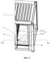
Fig. 2 is a schematic installation diagram of a drain valve assembly disclosed by an embodiment of the present application; -
Fig. 3 is an enlarged view of a dotted circle part A inFig. 2 ; -
Fig. 4 is a partial enlarged view of a sectional view made along a line B-B inFig. 2 ; -
Fig. 5 is an exploded view of a drain valve assembly disclosed by an embodiment of the present application; -
Fig. 6 is a schematic diagram of an upper cabinet body bottom plate disclosed by an embodiment of the present application; -
Fig. 7 is a schematic diagram of an internal structure of a closed-state drain valve disclosed by an embodiment of the present application; and -
Fig. 8 is a schematic diagram of an internal structure of an opened-state drain valve disclosed by an embodiment of the present application; - In the drawings, the drawings are not drawn to actual scale.
- Description of reference numerals:
- 1-cabinet body; 11-upper cabinet body; 111-upper cabinet body bottom plate; 1111-water guide plate; 1112-water guide box; 112-drain outlet; 12-lower cabinet body; 121-lower cabinet body bottom plate; 1211-first nut; 1212- first bolt; 122- drain valve installation port;
- 2-drain valve assembly; 21-drain valve; 211-valve core assembly; 2111-metal valve core; 2112-guide rod; 2113-third sealing member; 212-shell; 22-mounting plate; 221-second nut; 222-second bolt; 23-frame; 24-connecting bottom plate; 241-first through hole; 25-first sealing member; 26-second sealing member; 261-second through hole; and 27-upper pressing plate.
- Implementation modes of the present application are further described in detail below with reference to drawings and embodiments. The following detailed description of the embodiments and the drawings are used to illustrate principles of the present application by way of example, but should not be used to limit the scope of the present application, and in other words, the present application is not limited to the described embodiments.
- In the description of the present application, it should be noted that, unless otherwise stated, "plurality of" means two or more; the orientation or positional relationships indicated by the terms such as "upper", "lower", "left", "right", "inner" and "outer" are only for facilitating the description of the present application and simplifying the description, rather than indicating or implying that an apparatus or element referred to must have a particular orientation or be constructed and operated in a particular orientation, and therefore will not be interpreted as limiting the present application. In addition, the terms such as "first", "second" and "third" are only used for describing purposes, but cannot be understood as indicating or implying relative importance. "Vertical" is not strictly vertical, but within the allowable range of error. "Parallel" is not strictly parallel, but within the allowable range of error.
- A references herein to "an embodiment" in the present application means that a particular feature, structure, or characteristic described in combination with the embodiment can be included in at least one embodiment of the present application. The appearance of this phrase in various places in the Description does not necessarily refer to the same embodiment, nor is it a separate or alternative embodiment that is mutually exclusive from other embodiments. It is understood explicitly and implicitly by those skilled in the art that the embodiments described in the present application can be combined with other embodiments.
- Orientation words appearing in the following description are directions shown in the drawings, and do not limit a specific structure of the present application. In the description of the present application, it should be further noted that the terms "mounting", "connecting" and "connection" should be understood in a broad sense, unless otherwise explicitly specified or defined. For example, it may be a fixed connection, a detachable connection, or an integrated connection; and it may be a direct connection or an indirect connection through an intermediate medium. For those of ordinary skill in the art, the specific meanings of the above terms in the present application may be understood according to specific circumstances.
- In the present application, the term "and/or" is only an association relationship for describing associated objects, indicating that three relationships may exist. For example, A and/or B may represent three situations: A exists alone, both A and B exist, and B exists alone. In addition, the character "/" in the present application generally means that the associated objects before and after it are in an "or" relationship.
- In the embodiments of the present application, the same drawing reference numerals denote the same components, and for the sake of brevity, detailed descriptions of the same components are omitted in different embodiments. It should be understood that the thickness, length, width and other dimensions of the various components in the embodiments of the present application shown in the drawings, as well as the overall thickness, length, width and other dimensions of an integrated device, are for illustrative descriptions only, and should not constitute any limitation to the present application.
- "Plurality of " in the present application refers to two or more (including two).
- An energy storage battery cabinet has been more and more widely used in the fields of new energy, a smart grid, an energy-saving technology, etc. Battery cells are arranged inside the battery cabinet. The battery cells release heat during charging and discharging. In order to prevent the temperature of the battery cells from being too high, a cooling system is installed in the battery cabinet. However, when gas in the battery cabinet encounters condensed water at a lower temperature in a cooling pipe, the gas will condense into moisture on an outer wall of the pipe. If the moisture inside the battery cabinet cannot be drained in time, the battery cells will be damaged. Therefore, the battery cabinet is required to have a high waterproof level. In order to solve the drainage problem of the battery cabinet, the existing battery cabinet is provided with a drain outlet or a drain part. On one hand, the drain outlet is a through hole in a bottom plate of the battery cabinet. This type of solution has poor sealing performance, and corrosive gas outside a cabinet body can enter the cabinet and erode internal components of the battery cabinet. On the other hand, although the installation of the drain part on the bottom plate of the battery cabinet can achieve one-way sealed drainage, it is difficult to operate because a worker needs to enter the battery cabinet when installing the drain part, and to move the battery cells in the cabinet when detaching the drain part. Therefore, the inventor found out through research on this kind of battery cabinet that an installation port is formed in the bottom plate of the battery cabinet so that the drain part can be installed or detached from bottom to top, which increases the convenience of operation. In addition, the one-way sealed drainage of the battery cabinet can be achieved, and sealing performance is improved. Moreover, the occupation of the internal space of the battery cabinet by the drain part can be reduced, and the energy density of the battery cabinet is improved.
- The present application discloses a battery cabinet, which can be used in technical fields such as wind power plants, photovoltaic power plants and other new energy power plants or micro-grids.
- Referring to
Fig. 1 to Fig. 4 , the embodiment of the present application discloses a battery cabinet. The battery cabinet includes acabinet body 1 and adrain valve assembly 2. Thecabinet body 1 includes anupper cabinet body 11 and alower cabinet body 12, and theupper cabinet body 11 is used for accommodating battery cells. An upper cabinetbody bottom plate 111 is arranged at the bottom of theupper cabinet body 11, and provided with adrain outlet 112. Thelower cabinet body 12 includes a lower cabinetbody bottom plate 121 which is provided with a drainvalve installation port 122. Adrain valve assembly 2 is arranged in the drainvalve installation port 122 and is in butt joint with thedrain outlet 112. - The battery cabinet is a group of batteries composed of several battery cells, the cabinet body, a battery management system, installation structural parts, related functional components, etc., and has a battery cabinet structure, battery cabinet monitoring equipment, battery cabinet connectors, etc. meeting standards. The battery cabinet generally combines the multiple battery cells together as a power supply for use. The types of battery cabinets are distinguished according to the specifications, quantity and placement manners of battery cells, and can be divided into a vertical type, a horizontal type, etc. The battery cells may include a lithium-ion battery, a lithium-sulfur battery, a sodium-ion battery or a magnesium-ion battery, or the like, which are not limited by the embodiments of the present application. The battery management system is a control system for protecting use safety of power batteries, and mainly aims to intelligently manage and maintain various battery units, prevent the batteries from overcharging and overdischarging, prolong the service life of the batteries, and monitor states of the batteries. The installation structural parts may include a holder, a bracket, etc., which are not limited by the embodiments of the present application. The related functional components may include heat dissipation components, cooling components, thermal insulation components, drain parts, etc., which are not limited by the embodiments of the present application.
- The
cabinet body 1 refers to a main part of the battery cabinet, and thecabinet body 1 has spaces for placing the battery cells and other components. Thecabinet body 1 may be a rectangular cabinet body, which is not limited by the embodiments of the present application. Thecabinet body 1 may include a frame and a top plate, a bottom plate and side plates covering a surface of the frame. The top plate, the bottom plate and the side plates may be connected to the frame by welding, riveting, bolts, etc. The top plate, the bottom plate and the side plates may be connected by welding. An interior of thecabinet body 1 may be divided into several parts. For example, thecabinet body 1 is divided into theupper cabinet body 11 and thelower cabinet body 12. Theupper cabinet body 12 can accommodate the several battery cells, and thelower cabinet body 12 can accommodate pipes or other functional components. - The bottom plate of the battery cabinet is located at a lower edge of the
cabinet body 1 and is a load-bearing component of the battery cabinet. The bottom plate has basic safety performance such as stone impact resistance and scratch resistance. According to the position of the bottom plate in the battery cabinet, the bottom plate can be divided into the upper cabinetbody bottom plate 111 and the lower cabinetbody bottom plate 121. The upper cabinetbody bottom plate 111 is located at a lower edge of theupper cabinet body 11 and divides thecabinet body 1 into theupper cabinet body 11 and thelower cabinet body 12 . The lower cabinetbody bottom plate 121 is located at a lower edge of thelower cabinet body 12, separates the interior of the battery cabinet from an external environment, and can prevent external gas, dust, moisture, etc. from entering the battery cabinet. - The
drain valve assembly 2 is an assembly with a drainage function composed of a plurality of components, and the components cooperate with one another to realize one-way sealed drainage. Thedrain valve assembly 2 has a function of discharging accumulated water inside thecabinet body 1. Thedrain valve assembly 2 is installed at the drainvalve installation port 122 through a connectingbottom plate 24. An upper end of thedrain valve assembly 2 is in butt with thedrain outlet 112. The number ofdrain valve assemblies 2 is determined according to the capacity of the battery cabinet and the amount of drained condensed water, and may be one or more. During use of the battery cabinet, moisture is generated and deposited on the upper cabinetbody bottom plate 111. The moisture flows to thedrain outlet 112 due to gravity, and then is discharged out of the battery cabinet through thedrain valve assembly 2. - The drain
valve installation port 122 is located in the lower cabinetbody bottom plate 121 for fixing thedrain valve assembly 2. The shape of the drainvalve installation port 122 may be square or circular, which is not limited by the embodiments of the present application. The number of drainvalve installation ports 122 is matched with the number of thedrain valve assemblies 2 and may be one or more. - The connecting
bottom plate 24 is a component connecting thedrain valve assembly 2 with the battery cabinet. The connectingbottom plate 24 is welded to the bottom of theframe 23. Referring toFig. 5 , the connectingbottom plate 24 is provided with first throughholes 241, andfirst bolts 1212 can penetrate through the first throughholes 241 to fix thedrain valve assembly 2. Specifically, the lower cabinetbody bottom plate 121 is provided with first nuts 1211. During installation, thedrain valve assembly 2 is aligned with the drainvalve installation port 122; and the first throughholes 241 in the connectingbottom plate 24 are aligned with nut bottom holes of thefirst nuts 1211, and thedrain valve assembly 2 is fixed to thelower cabinet body 12 by thefirst bolts 1212. Correspondingly, during dismounting, thedrain valve assembly 2 can be dismounted only by loosening thefirst bolts 1212. - Furthermore, one or more first through
holes 241 may be arranged according to practical applications, which are not limited by the embodiments of the present application. In consideration of space utilization, three first throughholes 241 may be arranged. Correspondingly, the number of thefirst bolts 1212 is also three. Relative positions of the plurality of first throughholes 241 are set according to practical applications. For example, considering stability and convenience of installation, the relative positions of the three first throughholes 241 are set as a triangle to ensure uniform stress and form a stable support. - The
drain outlet 112 is a through hole located in the upper cabinetbody bottom plate 111, and the accumulated water flows out of theupper cabinet body 11 through thedrain outlet 112. The quantity, shape and position ofdrain outlets 112 are set according to practical applications. In some embodiments, there may be one ormore drain outlets 112; the shape of thedrain outlet 112 may be circular, square or other shapes; and the position of thedrain outlet 112 may be arranged in an edge of the upper cabinetbody bottom plate 111. After being installed, thedrain valve assembly 2 is in butt joint with thedrain outlet 112, so that the water flows into thedrain valve assembly 2 through thedrain outlet 112, thereby preventing the water flow from infiltrating into thelower cabinet body 12 and damaging other components in thelower cabinet body 12. - According to the embodiment of the present application, the
drain valve assembly 2 is detachably fixed to the lower cabinetbody bottom plate 121. Compared with a method for installing a drain part from the inside of a battery cabinet in the prior art, the operation of fixing thedrain valve assembly 2 through the drainvalve installation port 122 is more convenient and flexible, and the installation can be completed without entering the battery cabinet. When thedrain valve assembly 2 is disassembled, there is no need to move the battery cells in the cabinet. In addition, since thedrain valve assembly 2 is installed in thelower cabinet body 12, the occupation of an internal space of theupper cabinet body 11 by thedrain valve assembly 2 is reduced so that theupper cabinet body 11 can accommodate more battery cells, and the capacity density of the battery cabinet is improved. - Referring to
Fig. 2 andFig. 3 , thedrain valve assembly 2 is installed in the drainvalve installation port 122 from bottom to top. - Bottom-to-top installation means that the
drain valve assembly 2 is fixed through the connectingbottom plate 24 at the bottom, and the top of thedrain valve assembly 2 is not connected to theupper cabinet body 11. Specifically, thefirst bolts 1212 firstly pass through the first throughholes 241 in the connectingbottom plate 24 and then are connected to the first nuts 1211 on the lower cabinetbody bottom plate 121. Thedrain valve assembly 2 can be installed on the lowercabinet bottom plate 121 when thecabinet body 1 is manufactured, or can be installed on the lowercabinet bottom plate 121 after thecabinet body 1 is manufactured. - According to the embodiment of the present application, compared with a method for installing a drain part from top to bottom in the prior art, the bottom-to-top installation of the
drain valve assembly 2 can be achieved without entering thelower cabinet body 12, which reduces the operation difficulty of disassembly and assembly. In addition, when the internal space of thelower cabinet body 12 is narrow or is blocked by other components, the bottom-to-top installation manner is more convenient and feasible. - Referring to
Fig. 5 , thedrain valve assembly 2 includes adrain valve 21, a mountingplate 22, theframe 23 and the connectingbottom plate 24. The mountingplate 22 is connected to an inner wall of theframe 23, thedrain valve 21 is in sealed connection to the mountingplate 22, the connectingbottom plate 24 is arranged at the bottom of theframe 23, and theframe 23 is connected to a bottom surface of the lower cabinetbody bottom plate 121 through the connectingbottom plate 24. - The
drain valve 21 is a valve widely used in the water industry, is used for liquid discharge or liquid level control, is mainly used in cities, buildings, enterprise water supply and drainage projects, industrial and domestic sewage treatment, water conservancy projects and other fields. There are many types ofdrain valves 21, which can be divided into automatic, power-driven and manual according to power modes, and can be divided into a stop valve, a check valve, a ball valve, a steam trap, etc. according to purposes and functions. Different valves are suitable for different scenarios. - The
frame 23 is a component for accommodating and supporting thedrain valve 21, and can connect various components of thedrain valve assembly 2. Theframe 23 may be made of a metal alloy, etc., which is not limited by the embodiments of the present application. The shape of theframe 23 may be a cube, which is not limited by the embodiments of the present application. - The mounting
plate 22 is a component for mounting and fixing thedrain valve 21. The mountingplate 22 is embedded in theframe 23, and the mountingplate 22 and theframe 23 are integrally welded. Thedrain valve 21 is detachably connected to the mountingplate 22 through nut bottom holes of second nuts 221. In order to install thedrain valve 21 more stably, in some implementation modes, thedrain valve assembly 2 further includes an upperpressing plate 27. The upperpressing plate 27 is provided with one or more through holes (not shown in the figure), each through hole is correspondingly provided with asecond bolt 222, and the mountingplate 22 is provided with thesecond nuts 221 corresponding to thesecond bolts 222. Thesecond bolts 222 penetrate through the through holes of the upper pressingplate 27 and are connected to thesecond nuts 221, so that the upper pressingplate 27 presses a joint between thedrain valve 21 and the mountingplate 22. In order to further improve and optimize a waterproof effect, a joint between a side wall of the mountingplate 22 and theframe 23 is coated with waterproof glue to prevent water leakage at a connection gap between the mountingplate 22 and theframe 23. - According to the embodiment of the present application, the
drain valve 21 is in sealed connection to the mountingplate 22, the mountingplate 22 is connected to the inner wall of theframe 23, and the bottom of theframe 23 is welded to the connectingbottom plate 24. Theframe 23 plays a role of connecting the mountingplate 22 with the connectingbottom plate 24. The mountingplate 22 is capable of mounting and fixing thedrain valve 21. The upperpressing plate 27 presses thedrain valve 21 to improve sealing performance between thedrain valve 21 and the mountingplate 22. Thedrain valve assembly 2 is connected to the battery cabinet through the connectingbottom plate 24. - Referring to
Fig. 5 , thedrain valve assembly 2 further includes a first sealingmember 25, and thedrain valve 21 is in sealed connection to the mountingplate 22 through the first sealingmember 25. - The
first sealing member 25 can be made of elastic materials such as rubber and silica gel, which can improve sealing performance of connection between thedrain valve 21 and the mountingplate 22. Specifically, thedrain valve 21 is in sealed connection to an upper surface of the mountingplate 22 through the first sealingmember 25. After thedrain valve 21 is assembled on the mountingplate 22, an upper surface of the first sealingmember 25 is closely attached to thedrain valve 21, and a lower surface of the first sealingmember 25 is closely attached to the upper surface of the mountingplate 22 to form a first layer of sealing, thereby sealing a gap between thedrain valve 21 and the mountingplate 22. In order to further improve a sealing effect, thesecond nuts 221 on the mountingplate 22 are preferably boss nuts. When thedrain valve 21 is assembled too tightly on the mountingplate 22, bosses can be in contact with thedrain valve 21 to limit the position of thedrain valve 21 and prevent the sealing performance from being affected by the first sealingmember 25 being crushed when thedrain valve 21 and the mountingplate 22 are excessively assembled. - According to the embodiment of the present application, the
drain valve 21 is in sealed connection to the mountingplate 22 through the first sealingmember 25 so as to improve the sealing performance between thedrain valve 21 and the mountingplate 22. The bosses of thesecond nuts 221 prevent the first sealingmember 25 from being crushed by thedrain valve 21. - Referring to
Fig. 5 , thedrain valve assembly 2 further includes asecond sealing member 26 arranged between the connectingbottom plate 24 and the lower cabinetbody bottom plate 121. - The
second sealing member 26 can be made of elastic materials such as rubber and silica gel, which can improve the sealing performance of connection between the connectingbottom plate 24 and the lower cabinetbody bottom plate 121. Specifically, a lower surface of the second sealingmember 26 is bonded to an upper surface of the connectingbottom plate 24 by a sealant. Thesecond sealing member 26 is provided with second throughholes 261 concentric with the first throughholes 241, and the second throughholes 261 are matched with the first throughholes 241 in number and size. After thedrain valve assembly 2 is assembled on the lower cabinetbody bottom plate 121, an upper surface of the second sealingmember 26 is closely attached to a lower surface of the lower cabinetbody bottom plate 121 to form a second layer of sealing, thereby sealing a gap between the connectingbottom plate 24 and the lower cabinetbody bottom plate 121. Preferably, the shape of the second sealingmember 26 is consistent with that of the connectingbottom plate 24, which can further optimize the sealing effect. - According to the embodiment of the present application, the second sealing
member 26 is arranged between the connectingbottom plate 24 and the lower cabinetbody bottom plate 121 to improve the sealing performance between the connectingbottom plate 24 and the lower cabinetbody bottom plate 121. - Referring to
Fig. 2 ,Fig. 4 andFig. 6 , the upper cabinetbody bottom plate 111 includes awater guide plate 1111 and awater guide box 1112. An upper end of thewater guide box 1112 is connected to thewater guide plate 1111, and a lower end of thewater guide box 1112 is in butt joint with thedrain valve assembly 2. - The
water guide plate 1111 can make the accumulated water on the upper cabinetbody bottom plate 111 flow to thedrain outlet 112 to prevent the accumulated water from accumulating at the bottom of theupper cabinet body 11. - The
water guide box 1112 is a component connecting thewater guide plate 1111 with thedrain valve assembly 2, and the upper end of thewater guide box 1112 is welded to thewater guide plate 1111 as a whole. The lower end of thewater guide box 1112 is in butt joint with thedrain valve assembly 2. - Butt joint refers to mutual contact between end portions of various components. Specifically, butt joint means that an opening in the lower end of the
water guide box 1112 corresponds to an opening in the upper end of thedrain valve assembly 2 so that the accumulated water can flow into thedrain valve assembly 2. - According to the embodiment of the present application, water flow in the cabinet body flows, along the
water guide plate 1111, to thedrain valve assembly 2 via thewater guide box 1112 and is finally discharged out of the battery cabinet to realize one-way sealed drainage. - Referring to
Fig. 2 , according to the embodiment of the present application, thewater guide box 1112 is arranged on the side, close to a door panel of the battery cabinet, of the upper cabinetbody bottom plate 111. - The
water guide box 1112 is arranged on the side close to the door panel of the battery cabinet. Correspondingly, thedrain outlet 112 is formed in the side, close to the door panel of the battery cabinet, of the upper cabinetbody bottom plate 111, and the drainvalve installation port 122 is formed in the side, close to the door panel of the battery cabinet, of the lower cabinetbody bottom plate 121. In some embodiments, thewater guide box 1112 may be arranged at a left end of the side close to the door panel, which is not limited in this embodiment. Thedrain valve assembly 2 can be disassembled and assembled without going deep into the battery cabinet. Especially for a large battery cabinet with a large depth, disposing thewater guide box 1112 on the side close to the door panel simplifies the steps of disassembling and assembling thedrain valve assembly 2. - According to the embodiment of the present application, compared with an existing technical solution in which a
drain outlet 112 is formed in a middle of a bottom plate,thewater guide box 1112 is arranged on the side close to the door panel of the battery cabinet to reduce the operation difficulty of disassembling and assembling thedrain valve assembly 2. - Referring to
Fig. 4 , according to the embodiment of the present application, a lower edge of thewater guide box 1112 is lower than an upper edge of theframe 23, so that theframe 23 sleeves thewater guide box 1112. - In order to prevent the water flow from splashing to an exterior of the
drain valve assembly 2 when the water flow is large, the lower edge of thewater guide box 1112 is lower than the upper edge of theframe 23 so that theframe 23 can sleeve thewater guide box 1112. It can be understood that thewater guide box 1112 and theframe 23 overlap each other in a height direction. A length and a width of thewater guide box 1112 are smaller than those of theframe 23 to achieve a better nesting effect. - According to the embodiment of the present application, the lower edge of the
water guide box 1112 is lower than the upper edge of theframe 23, which can prevent the water flow from splashing out of thedrain valve assembly 2. - Referring to
Fig. 6 , according to the embodiment of the present application, thewater guide plate 1111 is provided with a drainage structure. The drainage structure downwards inclines towards the position of thewater guide box 1112. - The drainage structure can make the accumulated water stay in the
drain outlet 112 smoothly. The inclination of the drainage structure towards thewater guide box 1112 means that thewater guide plate 1111 inclines towards the position of thewater guide box 1112 to form an inclined plane, so that the position of thedrain outlet 112 is located at a lowest point of theupper cabinet body 11, and the accumulated water accumulated on the upper cabinetbody bottom plate 111 converges, under the action of gravity, to thedrain outlet 112 along the inclined plane of the drainage structure, and is discharged out of thecabinet body 1 through thedrain valve assembly 2. - According to the embodiment of the present application, the drainage structure downwards inclines towards the position of the
water guide box 1112 so that the accumulated water can flow out of the battery cabinet to the greatest extent. - Referring to
Fig. 7 andFig. 8 , according to the embodiment of the present application, thedrain valve 21 includes avalve core assembly 211 and ashell 212. Thevalve core assembly 211 is arranged in theshell 212. Theshell 212 is of a cylindrical structure, and the top of the cylindrical structure is provided with an outwards-turned edge. - The
drain valve 21 implements basic functions such as direction control, pressure control or flow control by means of thevalve core assembly 211. In the embodiment of the present application, the one-way sealed drainage function of thedrain valve 21 is realized by thevalve core assembly 211. Thedrain valve 21 can also be of other structures, as long as it can satisfy a drain function, such as a spring-type structure. - The
shell 212 is of the cylindrical structure with the outwards-turned edge at the top. It can be understood that the shape of theshell 212 is similar to a funnel, which can collect the water flow and improve drainage efficiency. An edge of an upper open end of theshell 212 is in butt joint with thewater guide box 1112, and theshell 212 is internally provided with a drainage channel. - According to the embodiment of the present application, the
drain valve 21 includes thevalve core assembly 211 and theshell 212 . One-way sealed drainage can be realized through thevalve core assembly 211. The water flow can be collected by the outwards-turned edge on the top of theshell 212. - Referring to
Fig. 7 andFig. 8 , according to the embodiment of the present application, thevalve core assembly 211 includes ametal valve core 2111, aguide rod 2112 and athird sealing member 2113. Themetal valve core 2111 movably sleeves theguide rod 2112. Magnetic substances are arranged on theguide rod 2112. The magnetic substances generate magnetic force to make themetal valve core 2111 close thedrain valve 21, and open thedrain valve 21 when downward acting force exerted on themetal valve core 2111 is greater than a preset value. - The
metal valve core 2111 is a main body of thevalve core assembly 211. Movement modes of themetal valve core 2111 can be divided into a rotary mode, a translation type, etc. Themetal valve core 2111 is arranged on the drainage channel in theshell 212, and the shape of themetal valve core 2111 is matched with that of a cross section of the drainage channel of theshell 212, and specifically, the shape of the cross section may be a circle or the like. - The shape of the
guide rod 2112 is matched with that of a cross section of themetal valve core 2111, and specifically, the shape of the cross section may be a circle or the like so that themetal valve core 2111 can sleeve theguide rod 2112. An upper end of theguide rod 2112 is provided with magnetic substances, specifically a magnet or the like. The magnetic substances can generate upward magnetic force on themetal valve core 2111, so that themetal valve core 2111 seals the drainage channel. - The
third sealing member 2113 may be made of elastic materials such as rubber and silica gel. Referring toFig. 7 , in a closed state of themetal valve core 2111, thethird sealing member 2113 can improve the sealing performance of connection between themetal valve core 2111 and theshell 212. Specifically, when themetal valve core 2111 is in the closed state, an upper surface of thethird sealing member 2113 is closely attached to a lower edge of theshell 212, so that a gap between themetal valve core 2111 and theshell 212 is sealed to achieve a third layer of sealing. - "Movably sleeves" means that the
metal valve core 2111 is movable inside theshell 212. Specifically, when themetal valve core 2111 moves upwards to a first state (namely, the closed state of the drain valve 21 ) under the action of the magnetic force of the magnetic substances, thevalve core assembly 211 seals the drainage channel; and when the downward acting force exerted, by the accumulated water, on themetal valve core 2111 is greater than the preset value, themetal valve core 2111 moves downwards to a second state (namely, the opened state of the drain valve 21), thereby conducting thedrain valve 21 to drain water. Directions of arrows inFig. 8 represent directions of the water flow. After the accumulated water is discharged, themetal valve core 2111 moves upwards again under the action of the magnetic force of the magnetic substances and returns to the first state, thereby sealing the drainage channel. - In addition, when an accident such as thermal runaway occurs inside the battery cabinet and after an air pressure inside the
cabinet body 1 reaches a certain threshold, themetal valve core 2111 can be automatically opened to release the pressure to prevent the accident. - According to the embodiment of the present application, the
valve core assembly 211 includes themetal valve core 2111, theguide rod 2112 and sealingrubber 2113. When the downward acting force exerted on themetal valve core 2111 is greater than the preset value, thedrain valve 21 is opened to realize automatic drainage. The magnetic substances on theguide rod 2112 generate the magnetic force to make themetal valve core 2111 close thedrain valve 21. Existing spring-loaded drainage assemblies are prone to rust during use, and consequently, drainage or seal failures are likely to happen. According to the embodiment of the present application, the magnetic substances control thevalve core assembly 211 to be opened and closed so that automatic drainage can be accurately realized; and the sealing performance of thevalve core assembly 211 can be improved by thethird sealing member 2113. - Although the present application has been described with reference to the preferred embodiments, various improvements can be made thereto and components thereof can be replaced with equivalents without departing from the scope of the present application. In particular, the technical features mentioned in the various embodiments can be combined in any manner as long as there is no structural conflict. The present application is not limited to the specific embodiments disclosed herein, but rather includes all technical solutions falling within the scope of the claims.
Claims (11)
- A battery cabinet, comprising:a cabinet body, wherein the cabinet body comprises an upper cabinet body and a lower cabinet body, the upper cabinet body is used for accommodating battery cells, the bottom of the upper cabinet body is provided with an upper cabinet body bottom plate, the upper cabinet body bottom plate is provided with a drain outlet, and the lower cabinet body comprises a lower cabinet body bottom plate which is provided with a drain valve installation port; anda drain valve assembly which is installed in the drain valve installation port and is in butt joint with the drain outlet.
- The battery cabinet according to claim 1, wherein the drain valve assembly is installed in the drain valve installation port from bottom to top.
- The battery cabinet according to claim 1 or 2, wherein the drain valve assembly comprises a drain valve, a mounting plate, a frame and a connecting bottom plate; the mounting plate is connected to an inner wall of the frame; the drain valve is in sealed connection to the mounting plate; the connecting bottom plate is arranged at the bottom of the frame; and the frame is connected to a bottom surface of the lower cabinet body bottom plate through the connecting bottom plate.
- The battery cabinet according to any one of claims 1 to 3, wherein the drain valve assembly further comprises a first sealing member, and the drain valve is in sealed connection to the mounting plate through the first sealing member.
- The battery cabinet according to claim 3, wherein the drain valve assembly further comprises a second sealing member, and the second sealing member is arranged between the connecting bottom plate and the lower cabinet body bottom plate.
- The battery cabinet according to claim 3 or 5, wherein an upper cabinet body bottom plate comprises a water guide plate and a water guide box; an upper end of the water guide box is connected to the water guide plate; and a lower end of the water guide box is in butt joint with the drain valve assembly.
- The battery cabinet according to claim 6, wherein the water guide box is arranged on the side, close to a door panel of the battery cabinet, of the upper cabinet body bottom plate.
- The battery cabinet according to claim 6 or 7, wherein a lower edge of the water guide box is lower than an upper edge of the frame, so that the frame sleeves the water guide box.
- The battery cabinet according to any one of claims 6 to 8, wherein the water guide plate is provided with a drainage structure; and the drainage structure downwards inclines towards the position of the water guide box.
- The battery cabinet according to any one of claims 1 to 9, wherein the drain valve comprises a valve core assembly and a shell; the valve core assembly is arranged in the shell; and the shell is of a cylindrical structure, and the top of the cylindrical structure is provided with an outwards-turned edge.
- The battery cabinet according to claim 10, wherein the valve core assembly comprises a metal valve core, a guide rod and a third sealing member; the metal valve core movably sleeves the guide rod; the guide rod is provided with magnetic substances; and when the magnetic substances generate magnetic force to make the metal valve core close the drain valve and downward acting force exerted on the metal valve core is greater than a preset value, the drain valve is opened.
Applications Claiming Priority (2)
| Application Number | Priority Date | Filing Date | Title |
|---|---|---|---|
| CN202111005838.6A CN115732872A (en) | 2021-08-30 | 2021-08-30 | Battery cabinet |
| PCT/CN2022/102964 WO2023029714A1 (en) | 2021-08-30 | 2022-06-30 | Battery cabinet |
Publications (2)
| Publication Number | Publication Date |
|---|---|
| EP4311001A1 true EP4311001A1 (en) | 2024-01-24 |
| EP4311001A4 EP4311001A4 (en) | 2025-01-15 |
Family
ID=85290959
Family Applications (1)
| Application Number | Title | Priority Date | Filing Date |
|---|---|---|---|
| EP22862855.8A Pending EP4311001A4 (en) | 2021-08-30 | 2022-06-30 | BATTERY CABINET |
Country Status (4)
| Country | Link |
|---|---|
| US (1) | US20240170823A1 (en) |
| EP (1) | EP4311001A4 (en) |
| CN (2) | CN119447741A (en) |
| WO (1) | WO2023029714A1 (en) |
Family Cites Families (26)
| Publication number | Priority date | Publication date | Assignee | Title |
|---|---|---|---|---|
| US2069297A (en) * | 1932-01-23 | 1937-02-02 | Stephens Pump Company | Valve |
| US5997049A (en) * | 1997-08-29 | 1999-12-07 | Furon Company | Adjustable leak-tight coupling system |
| US20070044846A1 (en) * | 2005-08-25 | 2007-03-01 | Transportation Research Corp. | Check valve |
| CN201753789U (en) * | 2010-07-08 | 2011-03-02 | 厦门松霖科技有限公司 | Magnetic check valve |
| KR20130056932A (en) * | 2011-11-23 | 2013-05-31 | 에스케이이노베이션 주식회사 | Battery pack |
| JP2014156958A (en) * | 2013-02-15 | 2014-08-28 | Evuc Kk | Show-case drainage system |
| WO2015087320A1 (en) * | 2013-12-09 | 2015-06-18 | Raval A.C.S. Ltd. | Draining device |
| DE102014014740A1 (en) * | 2014-10-09 | 2016-04-14 | A.RAYMOND et Cie. SCS | Shut-off body for a valve and valve with such a shut-off body |
| CN206213746U (en) * | 2016-08-02 | 2017-06-06 | 梅州新马陶瓷股份有限公司 | A kind of Combined ceramic tea tray |
| TWI623140B (en) * | 2016-09-30 | 2018-05-01 | 財團法人金屬工業研究發展中心 | Battery case for electric vehicle with heat dissipation and drainage structure |
| CN206412401U (en) * | 2017-01-23 | 2017-08-15 | 长城汽车股份有限公司 | Single slope drainage vent valve and battery bag |
| CN206864570U (en) * | 2017-03-17 | 2018-01-09 | 中信国安盟固利动力科技有限公司 | A kind of battery protecting apparatus |
| KR102280096B1 (en) * | 2017-10-17 | 2021-07-21 | 주식회사 엘지에너지솔루션 | Battery pack having function to block the inflow of leakage coolant |
| CN108396848B (en) * | 2018-05-09 | 2024-01-30 | 徐津 | Anti-blocking self-priming drainage valve core and related drainage equipment |
| CN208657212U (en) * | 2018-08-09 | 2019-03-26 | 常州贵鸿电气有限公司 | A condensate drainage device |
| CN109572919A (en) * | 2018-12-07 | 2019-04-05 | 南京壹久软件科技有限公司 | A kind of electric bicycle battery apparatus for placing |
| CN210852107U (en) * | 2019-08-08 | 2020-06-26 | 宿州市艾尔新能源有限公司 | Movable ring monitoring device of energy storage box |
| CN210663310U (en) * | 2019-08-08 | 2020-06-02 | 宿州市艾尔新能源有限公司 | Waterproof device of energy storage box |
| US12144130B2 (en) * | 2019-11-07 | 2024-11-12 | Nitto Denko Corporation | Ventilation component |
| JP7151691B2 (en) * | 2019-11-14 | 2022-10-12 | トヨタ自動車株式会社 | power storage device |
| US20230361440A1 (en) * | 2019-12-03 | 2023-11-09 | Sanyo Electric Co., Ltd. | Battery pack |
| CN211575725U (en) * | 2020-01-16 | 2020-09-25 | 东北农业大学 | Automatic waterlogging caused by excessive rainfall formula cabinet body of disinfection and stoving |
| EP3951225B1 (en) * | 2020-08-06 | 2024-09-18 | Illinois Tool Works, Inc. | A valve assembly and housing comprising the same |
| US11519510B1 (en) * | 2021-07-08 | 2022-12-06 | Saudi Arabian Oil Company | Relief valve seal holder |
| DE202021103675U1 (en) * | 2021-07-08 | 2022-10-13 | Liquitec Ag | Magnetic check valve |
| US11857761B2 (en) * | 2021-08-03 | 2024-01-02 | Carefusion 303, Inc. | Check valve |
-
2021
- 2021-08-30 CN CN202411561710.1A patent/CN119447741A/en active Pending
- 2021-08-30 CN CN202111005838.6A patent/CN115732872A/en active Pending
-
2022
- 2022-06-30 EP EP22862855.8A patent/EP4311001A4/en active Pending
- 2022-06-30 WO PCT/CN2022/102964 patent/WO2023029714A1/en not_active Ceased
-
2024
- 2024-01-23 US US18/420,715 patent/US20240170823A1/en active Pending
Also Published As
| Publication number | Publication date |
|---|---|
| CN115732872A (en) | 2023-03-03 |
| WO2023029714A1 (en) | 2023-03-09 |
| EP4311001A4 (en) | 2025-01-15 |
| CN119447741A (en) | 2025-02-14 |
| US20240170823A1 (en) | 2024-05-23 |
Similar Documents
| Publication | Publication Date | Title |
|---|---|---|
| EP3351888A1 (en) | Battery heat exchange system | |
| AU2022408296A1 (en) | Energy storage battery system | |
| KR20230105641A (en) | Battery pack with fire water storage tank and wall mount unit | |
| EP4135110A1 (en) | Battery cabinet | |
| EP4311001A1 (en) | Battery cabinet | |
| CN116742241B (en) | Battery box, battery module, energy storage system and electric equipment | |
| CN221226419U (en) | Battery pack | |
| CN221484303U (en) | Outdoor heat exchanger and heat pump air conditioner | |
| CN217720335U (en) | High-low voltage power distribution cabinet casing takes precautions against earthquakes | |
| CN216558481U (en) | Cooling water hydraulic pressure stabilizer of high-efficient computer lab | |
| CN212677475U (en) | Assembled outdoor cabinet | |
| CN221486620U (en) | Energy storage cabinet | |
| CN117832746A (en) | A battery module and energy storage system | |
| CN210744522U (en) | Substation Current Transformer Secondary Moisture Drive Box | |
| CN110416896B (en) | An intelligent automatic outdoor tide drive for substation outdoor cabinets | |
| CN223625633U (en) | Energy storage devices, charging networks and energy storage systems | |
| CN224082484U (en) | Energy storage cabinet and energy storage device | |
| CN221842139U (en) | Energy storage container bottom structure and energy storage container | |
| CN219998002U (en) | Transformer heat abstractor and transformer | |
| CN222380653U (en) | Power box applied to explosion hazard area | |
| CN223514180U (en) | Exhaust pressure release structure and battery container | |
| CN222355214U (en) | Heat abstractor of electrochemical energy storage equipment | |
| US20250158188A1 (en) | Energy storage apparatus | |
| CN110429494B (en) | Intelligent full-automatic moisture removing device for outdoor cabinet of transformer substation | |
| CN223693252U (en) | A waterproof battery box that is easy to disassemble |
Legal Events
| Date | Code | Title | Description |
|---|---|---|---|
| STAA | Information on the status of an ep patent application or granted ep patent |
Free format text: STATUS: THE INTERNATIONAL PUBLICATION HAS BEEN MADE |
|
| PUAI | Public reference made under article 153(3) epc to a published international application that has entered the european phase |
Free format text: ORIGINAL CODE: 0009012 |
|
| STAA | Information on the status of an ep patent application or granted ep patent |
Free format text: STATUS: REQUEST FOR EXAMINATION WAS MADE |
|
| 17P | Request for examination filed |
Effective date: 20231020 |
|
| AK | Designated contracting states |
Kind code of ref document: A1 Designated state(s): AL AT BE BG CH CY CZ DE DK EE ES FI FR GB GR HR HU IE IS IT LI LT LU LV MC MK MT NL NO PL PT RO RS SE SI SK SM TR |
|
| RAP1 | Party data changed (applicant data changed or rights of an application transferred) |
Owner name: CONTEMPORARY AMPEREX TECHNOLOGY(HONG KONG) LIMITED |
|
| DAV | Request for validation of the european patent (deleted) | ||
| DAX | Request for extension of the european patent (deleted) | ||
| A4 | Supplementary search report drawn up and despatched |
Effective date: 20241217 |
|
| RIC1 | Information provided on ipc code assigned before grant |
Ipc: H01M 50/20 20210101AFI20241211BHEP |