EP4310533A2 - Radar-based target tracker - Google Patents
Radar-based target tracker Download PDFInfo
- Publication number
- EP4310533A2 EP4310533A2 EP23186695.5A EP23186695A EP4310533A2 EP 4310533 A2 EP4310533 A2 EP 4310533A2 EP 23186695 A EP23186695 A EP 23186695A EP 4310533 A2 EP4310533 A2 EP 4310533A2
- Authority
- EP
- European Patent Office
- Prior art keywords
- radar
- image
- generate
- filtered
- targets
- Prior art date
- Legal status (The legal status is an assumption and is not a legal conclusion. Google has not performed a legal analysis and makes no representation as to the accuracy of the status listed.)
- Pending
Links
Images




Classifications
-
- G—PHYSICS
- G01—MEASURING; TESTING
- G01S—RADIO DIRECTION-FINDING; RADIO NAVIGATION; DETERMINING DISTANCE OR VELOCITY BY USE OF RADIO WAVES; LOCATING OR PRESENCE-DETECTING BY USE OF THE REFLECTION OR RERADIATION OF RADIO WAVES; ANALOGOUS ARRANGEMENTS USING OTHER WAVES
- G01S13/00—Systems using the reflection or reradiation of radio waves, e.g. radar systems; Analogous systems using reflection or reradiation of waves whose nature or wavelength is irrelevant or unspecified
- G01S13/88—Radar or analogous systems specially adapted for specific applications
- G01S13/89—Radar or analogous systems specially adapted for specific applications for mapping or imaging
- G01S13/90—Radar or analogous systems specially adapted for specific applications for mapping or imaging using synthetic aperture techniques, e.g. synthetic aperture radar [SAR] techniques
- G01S13/904—SAR modes
- G01S13/9047—Doppler beam sharpening mode
-
- G—PHYSICS
- G01—MEASURING; TESTING
- G01S—RADIO DIRECTION-FINDING; RADIO NAVIGATION; DETERMINING DISTANCE OR VELOCITY BY USE OF RADIO WAVES; LOCATING OR PRESENCE-DETECTING BY USE OF THE REFLECTION OR RERADIATION OF RADIO WAVES; ANALOGOUS ARRANGEMENTS USING OTHER WAVES
- G01S7/00—Details of systems according to groups G01S13/00, G01S15/00, G01S17/00
- G01S7/02—Details of systems according to groups G01S13/00, G01S15/00, G01S17/00 of systems according to group G01S13/00
- G01S7/41—Details of systems according to groups G01S13/00, G01S15/00, G01S17/00 of systems according to group G01S13/00 using analysis of echo signal for target characterisation; Target signature; Target cross-section
- G01S7/415—Identification of targets based on measurements of movement associated with the target
-
- G—PHYSICS
- G01—MEASURING; TESTING
- G01S—RADIO DIRECTION-FINDING; RADIO NAVIGATION; DETERMINING DISTANCE OR VELOCITY BY USE OF RADIO WAVES; LOCATING OR PRESENCE-DETECTING BY USE OF THE REFLECTION OR RERADIATION OF RADIO WAVES; ANALOGOUS ARRANGEMENTS USING OTHER WAVES
- G01S13/00—Systems using the reflection or reradiation of radio waves, e.g. radar systems; Analogous systems using reflection or reradiation of waves whose nature or wavelength is irrelevant or unspecified
- G01S13/02—Systems using reflection of radio waves, e.g. primary radar systems; Analogous systems
- G01S13/06—Systems determining position data of a target
- G01S13/42—Simultaneous measurement of distance and other co-ordinates
- G01S13/44—Monopulse radar, i.e. simultaneous lobing
- G01S13/449—Combined with MTI or Doppler processing circuits
-
- G—PHYSICS
- G01—MEASURING; TESTING
- G01S—RADIO DIRECTION-FINDING; RADIO NAVIGATION; DETERMINING DISTANCE OR VELOCITY BY USE OF RADIO WAVES; LOCATING OR PRESENCE-DETECTING BY USE OF THE REFLECTION OR RERADIATION OF RADIO WAVES; ANALOGOUS ARRANGEMENTS USING OTHER WAVES
- G01S13/00—Systems using the reflection or reradiation of radio waves, e.g. radar systems; Analogous systems using reflection or reradiation of waves whose nature or wavelength is irrelevant or unspecified
- G01S13/02—Systems using reflection of radio waves, e.g. primary radar systems; Analogous systems
- G01S13/50—Systems of measurement based on relative movement of target
- G01S13/52—Discriminating between fixed and moving objects or between objects moving at different speeds
- G01S13/522—Discriminating between fixed and moving objects or between objects moving at different speeds using transmissions of interrupted pulse modulated waves
- G01S13/524—Discriminating between fixed and moving objects or between objects moving at different speeds using transmissions of interrupted pulse modulated waves based upon the phase or frequency shift resulting from movement of objects, with reference to the transmitted signals, e.g. coherent MTi
- G01S13/5246—Discriminating between fixed and moving objects or between objects moving at different speeds using transmissions of interrupted pulse modulated waves based upon the phase or frequency shift resulting from movement of objects, with reference to the transmitted signals, e.g. coherent MTi post processors for coherent MTI discriminators, e.g. residue cancellers, CFAR after Doppler filters
-
- G—PHYSICS
- G01—MEASURING; TESTING
- G01S—RADIO DIRECTION-FINDING; RADIO NAVIGATION; DETERMINING DISTANCE OR VELOCITY BY USE OF RADIO WAVES; LOCATING OR PRESENCE-DETECTING BY USE OF THE REFLECTION OR RERADIATION OF RADIO WAVES; ANALOGOUS ARRANGEMENTS USING OTHER WAVES
- G01S13/00—Systems using the reflection or reradiation of radio waves, e.g. radar systems; Analogous systems using reflection or reradiation of waves whose nature or wavelength is irrelevant or unspecified
- G01S13/02—Systems using reflection of radio waves, e.g. primary radar systems; Analogous systems
- G01S13/50—Systems of measurement based on relative movement of target
- G01S13/52—Discriminating between fixed and moving objects or between objects moving at different speeds
- G01S13/536—Discriminating between fixed and moving objects or between objects moving at different speeds using transmission of continuous unmodulated waves, amplitude-, frequency-, or phase-modulated waves
-
- G—PHYSICS
- G01—MEASURING; TESTING
- G01S—RADIO DIRECTION-FINDING; RADIO NAVIGATION; DETERMINING DISTANCE OR VELOCITY BY USE OF RADIO WAVES; LOCATING OR PRESENCE-DETECTING BY USE OF THE REFLECTION OR RERADIATION OF RADIO WAVES; ANALOGOUS ARRANGEMENTS USING OTHER WAVES
- G01S13/00—Systems using the reflection or reradiation of radio waves, e.g. radar systems; Analogous systems using reflection or reradiation of waves whose nature or wavelength is irrelevant or unspecified
- G01S13/02—Systems using reflection of radio waves, e.g. primary radar systems; Analogous systems
- G01S13/50—Systems of measurement based on relative movement of target
- G01S13/58—Velocity or trajectory determination systems; Sense-of-movement determination systems
- G01S13/583—Velocity or trajectory determination systems; Sense-of-movement determination systems using transmission of continuous unmodulated waves, amplitude-, frequency-, or phase-modulated waves and based upon the Doppler effect resulting from movement of targets
-
- G—PHYSICS
- G01—MEASURING; TESTING
- G01S—RADIO DIRECTION-FINDING; RADIO NAVIGATION; DETERMINING DISTANCE OR VELOCITY BY USE OF RADIO WAVES; LOCATING OR PRESENCE-DETECTING BY USE OF THE REFLECTION OR RERADIATION OF RADIO WAVES; ANALOGOUS ARRANGEMENTS USING OTHER WAVES
- G01S13/00—Systems using the reflection or reradiation of radio waves, e.g. radar systems; Analogous systems using reflection or reradiation of waves whose nature or wavelength is irrelevant or unspecified
- G01S13/02—Systems using reflection of radio waves, e.g. primary radar systems; Analogous systems
- G01S13/50—Systems of measurement based on relative movement of target
- G01S13/58—Velocity or trajectory determination systems; Sense-of-movement determination systems
- G01S13/583—Velocity or trajectory determination systems; Sense-of-movement determination systems using transmission of continuous unmodulated waves, amplitude-, frequency-, or phase-modulated waves and based upon the Doppler effect resulting from movement of targets
- G01S13/584—Velocity or trajectory determination systems; Sense-of-movement determination systems using transmission of continuous unmodulated waves, amplitude-, frequency-, or phase-modulated waves and based upon the Doppler effect resulting from movement of targets adapted for simultaneous range and velocity measurements
-
- G—PHYSICS
- G01—MEASURING; TESTING
- G01S—RADIO DIRECTION-FINDING; RADIO NAVIGATION; DETERMINING DISTANCE OR VELOCITY BY USE OF RADIO WAVES; LOCATING OR PRESENCE-DETECTING BY USE OF THE REFLECTION OR RERADIATION OF RADIO WAVES; ANALOGOUS ARRANGEMENTS USING OTHER WAVES
- G01S13/00—Systems using the reflection or reradiation of radio waves, e.g. radar systems; Analogous systems using reflection or reradiation of waves whose nature or wavelength is irrelevant or unspecified
- G01S13/66—Radar-tracking systems; Analogous systems
-
- G—PHYSICS
- G01—MEASURING; TESTING
- G01S—RADIO DIRECTION-FINDING; RADIO NAVIGATION; DETERMINING DISTANCE OR VELOCITY BY USE OF RADIO WAVES; LOCATING OR PRESENCE-DETECTING BY USE OF THE REFLECTION OR RERADIATION OF RADIO WAVES; ANALOGOUS ARRANGEMENTS USING OTHER WAVES
- G01S13/00—Systems using the reflection or reradiation of radio waves, e.g. radar systems; Analogous systems using reflection or reradiation of waves whose nature or wavelength is irrelevant or unspecified
- G01S13/66—Radar-tracking systems; Analogous systems
- G01S13/72—Radar-tracking systems; Analogous systems for two-dimensional [2D] tracking, e.g. combination of angle and range tracking, track-while-scan radar
- G01S13/723—Radar-tracking systems; Analogous systems for two-dimensional [2D] tracking, e.g. combination of angle and range tracking, track-while-scan radar by using numerical data
- G01S13/726—Multiple target tracking
-
- G—PHYSICS
- G01—MEASURING; TESTING
- G01S—RADIO DIRECTION-FINDING; RADIO NAVIGATION; DETERMINING DISTANCE OR VELOCITY BY USE OF RADIO WAVES; LOCATING OR PRESENCE-DETECTING BY USE OF THE REFLECTION OR RERADIATION OF RADIO WAVES; ANALOGOUS ARRANGEMENTS USING OTHER WAVES
- G01S7/00—Details of systems according to groups G01S13/00, G01S15/00, G01S17/00
- G01S7/02—Details of systems according to groups G01S13/00, G01S15/00, G01S17/00 of systems according to group G01S13/00
- G01S7/28—Details of pulse systems
- G01S7/285—Receivers
- G01S7/292—Extracting wanted echo-signals
- G01S7/2921—Extracting wanted echo-signals based on data belonging to one radar period
- G01S7/2922—Extracting wanted echo-signals based on data belonging to one radar period by using a controlled threshold
-
- G—PHYSICS
- G01—MEASURING; TESTING
- G01S—RADIO DIRECTION-FINDING; RADIO NAVIGATION; DETERMINING DISTANCE OR VELOCITY BY USE OF RADIO WAVES; LOCATING OR PRESENCE-DETECTING BY USE OF THE REFLECTION OR RERADIATION OF RADIO WAVES; ANALOGOUS ARRANGEMENTS USING OTHER WAVES
- G01S7/00—Details of systems according to groups G01S13/00, G01S15/00, G01S17/00
- G01S7/02—Details of systems according to groups G01S13/00, G01S15/00, G01S17/00 of systems according to group G01S13/00
- G01S7/28—Details of pulse systems
- G01S7/285—Receivers
- G01S7/292—Extracting wanted echo-signals
- G01S7/2923—Extracting wanted echo-signals based on data belonging to a number of consecutive radar periods
- G01S7/2927—Extracting wanted echo-signals based on data belonging to a number of consecutive radar periods by deriving and controlling a threshold value
-
- G—PHYSICS
- G01—MEASURING; TESTING
- G01S—RADIO DIRECTION-FINDING; RADIO NAVIGATION; DETERMINING DISTANCE OR VELOCITY BY USE OF RADIO WAVES; LOCATING OR PRESENCE-DETECTING BY USE OF THE REFLECTION OR RERADIATION OF RADIO WAVES; ANALOGOUS ARRANGEMENTS USING OTHER WAVES
- G01S7/00—Details of systems according to groups G01S13/00, G01S15/00, G01S17/00
- G01S7/02—Details of systems according to groups G01S13/00, G01S15/00, G01S17/00 of systems according to group G01S13/00
- G01S7/35—Details of non-pulse systems
- G01S7/352—Receivers
- G01S7/354—Extracting wanted echo-signals
-
- G—PHYSICS
- G01—MEASURING; TESTING
- G01S—RADIO DIRECTION-FINDING; RADIO NAVIGATION; DETERMINING DISTANCE OR VELOCITY BY USE OF RADIO WAVES; LOCATING OR PRESENCE-DETECTING BY USE OF THE REFLECTION OR RERADIATION OF RADIO WAVES; ANALOGOUS ARRANGEMENTS USING OTHER WAVES
- G01S7/00—Details of systems according to groups G01S13/00, G01S15/00, G01S17/00
- G01S7/02—Details of systems according to groups G01S13/00, G01S15/00, G01S17/00 of systems according to group G01S13/00
- G01S7/41—Details of systems according to groups G01S13/00, G01S15/00, G01S17/00 of systems according to group G01S13/00 using analysis of echo signal for target characterisation; Target signature; Target cross-section
- G01S7/411—Identification of targets based on measurements of radar reflectivity
-
- G—PHYSICS
- G01—MEASURING; TESTING
- G01S—RADIO DIRECTION-FINDING; RADIO NAVIGATION; DETERMINING DISTANCE OR VELOCITY BY USE OF RADIO WAVES; LOCATING OR PRESENCE-DETECTING BY USE OF THE REFLECTION OR RERADIATION OF RADIO WAVES; ANALOGOUS ARRANGEMENTS USING OTHER WAVES
- G01S7/00—Details of systems according to groups G01S13/00, G01S15/00, G01S17/00
- G01S7/02—Details of systems according to groups G01S13/00, G01S15/00, G01S17/00 of systems according to group G01S13/00
- G01S7/41—Details of systems according to groups G01S13/00, G01S15/00, G01S17/00 of systems according to group G01S13/00 using analysis of echo signal for target characterisation; Target signature; Target cross-section
- G01S7/414—Discriminating targets with respect to background clutter
-
- H—ELECTRICITY
- H04—ELECTRIC COMMUNICATION TECHNIQUE
- H04B—TRANSMISSION
- H04B17/00—Monitoring; Testing
- H04B17/30—Monitoring; Testing of propagation channels
- H04B17/309—Measuring or estimating channel quality parameters
- H04B17/318—Received signal strength
-
- H—ELECTRICITY
- H04—ELECTRIC COMMUNICATION TECHNIQUE
- H04B—TRANSMISSION
- H04B17/00—Monitoring; Testing
- H04B17/30—Monitoring; Testing of propagation channels
- H04B17/309—Measuring or estimating channel quality parameters
- H04B17/364—Delay profiles
-
- H—ELECTRICITY
- H04—ELECTRIC COMMUNICATION TECHNIQUE
- H04W—WIRELESS COMMUNICATION NETWORKS
- H04W52/00—Power management, e.g. Transmission Power Control [TPC] or power classes
- H04W52/04—Transmission power control [TPC]
- H04W52/18—TPC being performed according to specific parameters
- H04W52/28—TPC being performed according to specific parameters using user profile, e.g. mobile speed, priority or network state, e.g. standby, idle or non-transmission
- H04W52/283—Power depending on the position of the mobile
-
- G—PHYSICS
- G01—MEASURING; TESTING
- G01S—RADIO DIRECTION-FINDING; RADIO NAVIGATION; DETERMINING DISTANCE OR VELOCITY BY USE OF RADIO WAVES; LOCATING OR PRESENCE-DETECTING BY USE OF THE REFLECTION OR RERADIATION OF RADIO WAVES; ANALOGOUS ARRANGEMENTS USING OTHER WAVES
- G01S13/00—Systems using the reflection or reradiation of radio waves, e.g. radar systems; Analogous systems using reflection or reradiation of waves whose nature or wavelength is irrelevant or unspecified
- G01S13/02—Systems using reflection of radio waves, e.g. primary radar systems; Analogous systems
- G01S13/06—Systems determining position data of a target
- G01S13/08—Systems for measuring distance only
- G01S13/32—Systems for measuring distance only using transmission of continuous waves, whether amplitude-, frequency-, or phase-modulated, or unmodulated
- G01S13/34—Systems for measuring distance only using transmission of continuous waves, whether amplitude-, frequency-, or phase-modulated, or unmodulated using transmission of continuous, frequency-modulated waves while heterodyning the received signal, or a signal derived therefrom, with a locally-generated signal related to the contemporaneously transmitted signal
- G01S13/343—Systems for measuring distance only using transmission of continuous waves, whether amplitude-, frequency-, or phase-modulated, or unmodulated using transmission of continuous, frequency-modulated waves while heterodyning the received signal, or a signal derived therefrom, with a locally-generated signal related to the contemporaneously transmitted signal using sawtooth modulation
-
- G—PHYSICS
- G01—MEASURING; TESTING
- G01S—RADIO DIRECTION-FINDING; RADIO NAVIGATION; DETERMINING DISTANCE OR VELOCITY BY USE OF RADIO WAVES; LOCATING OR PRESENCE-DETECTING BY USE OF THE REFLECTION OR RERADIATION OF RADIO WAVES; ANALOGOUS ARRANGEMENTS USING OTHER WAVES
- G01S13/00—Systems using the reflection or reradiation of radio waves, e.g. radar systems; Analogous systems using reflection or reradiation of waves whose nature or wavelength is irrelevant or unspecified
- G01S13/88—Radar or analogous systems specially adapted for specific applications
- G01S13/93—Radar or analogous systems specially adapted for specific applications for anti-collision purposes
- G01S13/931—Radar or analogous systems specially adapted for specific applications for anti-collision purposes of land vehicles
-
- G—PHYSICS
- G01—MEASURING; TESTING
- G01S—RADIO DIRECTION-FINDING; RADIO NAVIGATION; DETERMINING DISTANCE OR VELOCITY BY USE OF RADIO WAVES; LOCATING OR PRESENCE-DETECTING BY USE OF THE REFLECTION OR RERADIATION OF RADIO WAVES; ANALOGOUS ARRANGEMENTS USING OTHER WAVES
- G01S7/00—Details of systems according to groups G01S13/00, G01S15/00, G01S17/00
- G01S7/02—Details of systems according to groups G01S13/00, G01S15/00, G01S17/00 of systems according to group G01S13/00
- G01S7/28—Details of pulse systems
- G01S7/285—Receivers
- G01S7/288—Coherent receivers
- G01S7/2883—Coherent receivers using FFT processing
Definitions
- the present disclosure relates generally to an electronic system and method, and, in particular embodiments, to a radar-based target tracker.
- the distance between the radar and a target is determined by transmitting a frequency modulated signal, receiving a reflection of the frequency modulated signal (also referred to as the echo), and determining a distance based on a time delay and/or frequency difference between the transmission and reception of the frequency modulated signal.
- some radar systems include a transmitting antenna for transmitting the radio-frequency (RF) signal, and a receiving antenna for receiving the reflected RF signal, as well as the associated RF circuits used to generate the transmitted signal and to receive the RF signal.
- multiple antennas may be used to implement directional beams using phased array techniques.
- a multiple-input and multiple-output (MIMO) configuration with multiple chipsets can be used to perform coherent and non-coherent signal processing.
- a method includes: receiving a range-Doppler image (RDI) based on raw data from a radar sensor; performing moving target indication (MTI) filtering on the RDI to generate a first filtered radar image; performing constant false alarm rate (CFAR) detection on the first filtered radar image to generate a second filtered radar image; performing minimum variance distortionless response (MVDR) beamforming on the second filtered radar image to generate a range-angle image (RAI); performing CFAR detection on the RAI to generate a third filtered radar image; generating a point set based on the third filtered radar image; clustering targets of the point set; and tracking at least one of the clustered targets using a Kalman filter.
- RDI range-Doppler image
- MMI moving target indication
- CFAR constant false alarm rate
- MVDR minimum variance distortionless response
- RAI range-angle image
- a millimeter-wave radar system includes: a millimeter-wave radar sensor configured to transmit radar signals and receive reflected radar signals; and a processing system configured to: generate a range-Doppler image (RDI) based on the reflected radar signals, perform moving target indication (MTI) filtering on the RDI to generate a first filtered radar image, perform constant false alarm rate (CFAR) detection on the first filtered radar image to generate a second filtered radar image, perform minimum variance distortionless response (MVDR) beamforming on the second filtered radar image to generate a range-angle image (RAI), perform CFAR detection on the RAI to generate a third filtered radar image, generate a point set based on the third filtered radar image, cluster targets of the point set, and track at least one of the clustered targets using a Kalman filter.
- RDI range-Doppler image
- MMI moving target indication
- CFAR constant false alarm rate
- MVDR minimum variance distortionless response
- RAI range-angle image
- a device includes: a millimeter-wave radar sensor configured to transmit radar signals and receive reflected radar signals; a communication device including a transmitter configured to radiate power with a first intensity; and a processing system configured to: generate a range-Doppler image (RDI) based on the reflected radar signals, perform moving target indication (MTI) filtering on the RDI to generate a first filtered radar image, perform constant false alarm rate (CFAR) detection on the first filtered radar image to generate a second filtered radar image, perform minimum variance distortionless response (MVDR) beamforming on the second filtered radar image to generate a range-angle image (RAI), perform CFAR detection on the RAI to generate a third filtered radar image, generate a point set based on the third filtered radar image, cluster targets of the point set, track at least one of the clustered targets, and when a first target of the tracked clustered targets is detected within a predetermined distance from the transmitter of the communication device, cause a reduction of the radiated
- RDI range
- Embodiments of the present invention will be described in specific contexts, e.g., a radar-based short-range target tracker, which may be used in applications such as safety-related applications and human machine interface (HMI). Some embodiments may be used in other applications.
- a radar-based short-range target tracker which may be used in applications such as safety-related applications and human machine interface (HMI).
- HMI human machine interface
- a radar processing chain detects and tracks short-range targets. Static targets and clutter are removed by performing moving target indication (MTI) filtering on radar-Doppler images (RDIs). Constant false alarm rate (CFAR) is performed on the filtered RDIs before performing digital beamforming, which may advantageously reduce the computational complexity of the radar processing chain, which may allow for real-time operation.
- MMI moving target indication
- RDIs radar-Doppler images
- CFAR Constant false alarm rate
- Embodiments of the present invention may be used in safety applications, such as by automatically causing the reduction of radiated power by a radio communication transmitter when a human (or a portion of a human) is near the radio communication transmitter and/or by warning a user when the user is too close to a predetermined location.
- Embodiments of the present invention may also be used in HMI applications, such as for detecting the actuation of virtual buttons.
- a radar such as a millimeter-wave radar, may be used to detect and track one or more (e.g., short-range) targets.
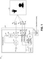
- Figure 1 shows a schematic diagram of millimeter-wave radar system 100, according to an embodiment of the present invention.
- Millimeter-wave radar system 100 includes millimeter-wave radar sensor 102 and processing system 104.
- millimeter-wave radar sensor 102 operates as a frequency-modulated continuous-wave (FMCW) radar sensor and transmits a plurality of TX radar signals 106, such as chirps, towards scene 120 using one or more transmitter (TX) antenna 114.
- the radar signals 106 are generated using RF and analog circuits 130.
- the radar signals 106 may be, e.g., in the 20 GHz to 122 GHz range. Other frequencies may also be used.
- the field of view of millimeter-wave radar sensor 102 covering scene 120 has a short-range, such as below 1 meter, such as within 35 cm.
- the objects in scene 120 may include one or more static or moving objects, such as a surface (e.g., table, countertop, etc.), a keyboard, a wall, and a portion of a human, such as a hand, head, or finger. Other objects may also be present in scene 120.
- the radar signals 106 are reflected by objects in scene 120.
- the reflected radar signals 108 which are also referred to as the echo signal, are received by a plurality of receiving (RX) antennas.
- RF and analog circuits 130 processes the received reflected radar signals 108 using, e.g., band-pass filters (BPFs), low-pass filters (LPFs), mixers, low-noise amplifier (LNA), and/or intermediate frequency (IF) amplifiers in ways known in the art to generate an analog signal x outa (t) and x outb (t)
- BPFs band-pass filters
- LPFs low-pass filters
- LNA low-noise amplifier
- IF intermediate frequency
- the analog signal x outa (t) and x outb (t) are converted to raw digital data x out_dig ( n ) using analog-to-digital converter (ADC) 112.
- ADC analog-to-digital converter
- the raw digital data x out_dig ( n ) is processed by processing system 104 to detect one or more targets and their position. In some embodiments, processing system 104 may also be used to track one or more targets in scene 120.
- Figure 1 illustrates a radar system with two receiver antennas 116 (antennas 116a and 116b), it is understood that more than two receiver antennas 116, such as three or more, may also be used. In some embodiments, using more receiver antennas 116 may result in higher spatial resolution.
- Figure 1 illustrates a radar system with a single transmitter antenna 114, it is understood that more than one transmitter antenna 114, such as two or more, may also be used.
- Controller 110 controls one or more circuits of millimeter-wave radar sensor 102, such as RF and analog circuit 130 and/or ADC 112. Controller 110 may be implemented, e.g., as a custom digital or mixed signal circuit, for example. Controller 110 may also be implemented in other ways, such as using a general-purpose processor or controller, for example. In some embodiments, processing system 104 implements a portion or all of controller 110.
- Processing system 104 may be implemented with a general-purpose processor, controller or digital signal processor (DSP) that includes, for example, combinatorial circuits coupled to a memory.
- processing system 104 may be implemented as an application specific integrated circuit (ASIC).
- ASIC application specific integrated circuit
- processing system 104 may be implemented with an ARM, RISC, or x86 architecture, for example.
- processing system 104 may include an artificial intelligence (AI) accelerator.
- AI artificial intelligence
- Some embodiments may use a combination of hardware accelerator and software running on a DSP or general-purpose microcontroller. Other implementations are also possible.
- millimeter-wave radar sensor 102 and a portion or all of processing system 104 may be implemented inside the same integrated circuit (IC).
- IC integrated circuit
- millimeter-wave radar sensor 102 and a portion or all of processing system 104 may be implemented in respective semiconductor substrates that are integrated in the same package.
- millimeter-wave radar sensor 102 and a portion or all of processing system 104 may be implemented in the same monolithic semiconductor substrate.
- millimeter-wave radar sensor 102 and processing system 104 are implemented in respective integrated circuits.
- a plurality of integrated circuits is used to implement millimeter-wave radar sensor 102.
- a plurality of integrated circuits is used to implement processing system 104.
- Other implementations are also possible.
- RF and analog circuits 130 may be implemented, e.g., as shown in Figure 1 .
- VCO voltage-controlled oscillator
- the VCO 136 is controlled by PLL 134, which receives a reference clock signal (e.g., 80 MHz) from reference oscillator 132.
- PLL 134 is controlled by a loop that includes frequency divider 138 and amplifier 140.
- Amplifier 137 may be used to drive transmitting antenna 114.
- the TX radar signals 106 transmitted by transmitting antenna 114 are reflected by objects in scene 120 and received by receiving antennas 116a and 116b.
- the echo received by receiving antennas 116a and 116b are mixed with a replica of the signal transmitted by transmitting antenna 114 using mixer 146a and 146b, respectively, to produce respective intermediate frequency (IF) signals x IFa ( t ) x IFb ( t ) (also known as beat signals).
- IF intermediate frequency
- the beat signals x IFa ( t ) and x IFb ( t ) have a bandwidth between 10 kHz and 1 MHz. Beat signals with a bandwidth lower than 10 kHz or higher than 1 MHz is also possible.
- Amplifiers 145a and 145b may be used to receive the reflected radar signals from antennas 116a and 116b, respectively.
- Beat signals x IFa ( t ) x IFb ( t ) are filtered with respective low-pass filters (LPFs) 148a and 148b and then sampled by ADC 112.
- ADC 112 is advantageously capable of sampling the filtered beat signals x outa ( t ) x outb ( t ) with a sampling frequency that is much smaller than the frequency of the signal received by receiving antennas 116a and 116b.
- FMCW radars therefore, advantageously allows for a compact and low cost implementation of ADC 112, in some embodiments.
- ADC 112 is a 12-bit ADC with multiple inputs. ADCs with higher resolution, such as 14-bits or higher, or with lower resolution, such as 10-bits, or lower, may also be used. In some embodiments, an ADC per receiver antenna may be used. Other implementations are also possible.
- FIG. 2 shows a sequence of chirps 106 transmitted by TX antenna 114, according to an embodiment of the present invention.
- chirps 106 are organized in a plurality of frames (also referred to as physical frames) and may be implemented as up-chirps.
- Some embodiments may use down-chirps or a combination of up-chirps and down-chirps, such as up-down chirps and down-up chirps.
- Other waveform shapes may also be used.
- each frame may include a plurality of chirps 106 (also referred to, generally, as pulses).
- the number of chirps in a frame is 64.
- Some embodiments may include more than 64 chirps per frame, such as 96 chirps, 128 chirps, 256 chirps, or more, or less than 64 chirps per frame, such as 32 chirps or less.
- frames are repeated every FT time.
- FT time is 50 ms.
- a different FT time may also be used, such as more than 50 ms, such as 60 ms, 100 ms, 200 ms, or more, or less than 50 ms, such as 45 ms, 40 ms, or less.
- the FT time is selected such that the time between the beginning of the last chirp of frame n and the beginning of the first chirp of frame n +1 is equal to PRT.
- Other embodiments may use or result in a different timing.
- the time between chirps of a frame is generally referred to as pulse repetition time (PRT).
- PRT pulse repetition time
- the PRT is 5 ms.
- a different PRT may also be used, such as less than 5 ms, such as 4 ms, 2 ms, 0.5 ms, or less, or more than 5 ms, such as 6 ms, or more.
- the duration of the chirp (from start to finish) is generally referred to as chirp time (CT).
- CT chirp time
- the chirp time may be, e.g., 64 ⁇ s. Higher chirp times, such as 128 ⁇ s, or higher, may also be used. Lower chirp times, may also be used.
- the chirp bandwidth may be, e.g., 4 GHz. Higher bandwidth, such as 6 GHz or higher, or lower bandwidth, such as 2 GHz, 1 GHz, or lower, may also be possible.
- the sampling frequency of millimeter-wave radar sensor 102 may be, e.g., 1 MHz. Higher sampling frequencies, such as 2 MHz or higher, or lower sampling frequencies, such as 500 kHz or lower, may also be possible.
- the number of samples used to generate a chirp may be, e.g., 64 samples.
- Figure 3 shows a flow chart of embodiment method 300 for detecting and tracking short-range targets, according to an embodiment of the present invention.
- Method 300 may be implemented by processing system 104.
- a range fast Fourier transform is performed on the raw digital data x out_dig ( n ) (e.g., on data from each receiving channel, e.g., from each receiving antenna 116). For example, in some embodiments, a windowed FFT having a length of a chirp (e.g., 106) is calculated for each of a predetermined number of chirps (e.g., all chirps) in a frame. The result of the range FFT is an indication of energy distribution across ranges for each chirp.
- FFT range fast Fourier transform
- a Doppler FFT is performed on the out range FFT data (e.g., for each receiving antenna 116) generated during step 302. For example, in some embodiments, an FFT is calculated across each range bin over a number of consecutive periods to extract Doppler information.
- the result of step 304 are range Doppler maps (also known are range-Doppler images or RDIs) for each of the receiving channels (e.g., for each receiving antenna 116).
- two-dimensional (2D) moving target indication (MTI) filtering is applied to each RDI to generate first filtered images.
- performing MTI filtering serves to discriminate a target against the clutter.
- a target e.g., a hand
- information about the background e.g., keyboard, surface, etc.
- the 2D MTI filter is implemented as a first order finite impulse response (FIR) filter.
- target detection is performed using constant false alarm rate (CFAR), such as ordered-statistic (OS) CFAR (OS-CFAR) on the filtered RDIs generated during step 306 to generated second filtered images (also referred to as RD masked detection images).
- CFAR constant false alarm rate
- OS ordered-statistic
- OS-CFAR ordered-statistic CFAR
- the CFAR detector generates a detection image in which, e.g., "ones" represent targets and "zeros" represent non-targets based on the power levels of the RDI when compared with a, e.g., predetermined threshold.
- the RD detection image operates as a mask and is multiplied by the original RDI (output of step 306) to obtain an RD masked image (at the output of step 308) in which only details of the detected targets are non-zero.
- detection of targets during step 308 is advantageously enabled by the relatively high signal-to-noise ratio (SNR) of moving targets due to the short-range field of view of millimeter-wave radar sensor 102.
- SNR signal-to-noise ratio
- the performance of steps 306, 308 and 310 advantageously allows for the detection of macro-motions as well as micro-motions of targets while ignoring non-targets (e.g., background, e.g., static, clutter).
- non-targets e.g., background, e.g., static, clutter
- performing target detecting on the RDIs before performing digital beamforming advantageously reduced computational complexity and allows for real-time operation.
- step 310 digital beamforming (e.g., 1D Capon) is applied to estimate angle from the data across virtual channels from the antenna array configuration for each range that has passed step 308 to generate 2D range-angle image (RAI).
- 1D digital beamforming
- RAI range-angle image
- target detection is performed using CFAR (e.g., OS-CFAR) on the RAI detection images generated during step 310 to generate third filtered images (also referred to as RA masked detection images).
- the CFAR detector generates a detection image in which, e.g., "ones” represent targets and "zeros" represent non-targets based on the power levels of the RAI when compared with a, e.g., predetermined threshold.
- the RA detection image operates as a mask and is multiplied by the original RAI (output of step 310) to obtain an RA masked detection image (at the output of step 312) in which only details of the detected targets are non-zero.
- step 314 a conversion from Polar coordinates to Cartesian coordinates is performed. In some embodiments, step 314 is omitted.
- each detection point includes: 2D coordinates, a signal strength value (indicative of the signal strength of target located at the 2D coordinates), and a Doppler value (indicative of the level of movement of the target at the 2D coordinates).
- the 2D coordinates are Cartesian coordinates (e.g., x, y) (e.g., if step 314 is performed).
- the 2D coordinates are Polar coordinates (e.g., range and angle) (e.g., if step 314 is not performed).
- each point of the set of detection points include 2D coordinates.
- each point of the set of detection points include 3D coordinates.
- the points (targets) of the set of detection points are clustered, e.g., using a density-based spatial clustering of applications with noise (DBSCAN) algorithm to associate points (targets) to clusters.
- DBSCAN density-based spatial clustering of applications with noise
- the output of DBSCAN is one or more groupings (clusters) of detected points, so that each grouping is associated with a respective target.
- each clustered target is represented as a single target having a point location, which may be the centroid of the cluster.
- a human hand may appear as a collection of targets before step 318. After step 318, a single point (e.g., corresponding to a geometric center of the hand) is used to represent the human hand.
- using Cartesian coordinates advantageously allows for an easier (e.g., less computationally expensive) implementation of the clustering step (318) since Cartesian coordinates are advantageously linear irrespective of the range.
- the same threshold e.g., clustering points within 6 cm
- the detected clusters are associated to respective tracks, e.g., using a probabilistic data association filter (PDAF) or nearest neighbor approach.
- PDAF probabilistic data association filter
- a (e.g., unscented) Kalman filter is used to filter and smoothen the tracks.
- all features of the clusters e.g., coordinates, signal strength value, and Doppler value
- the Kalman filter may only track a subset of the features of the cluster (e.g., just the coordinates, such as (x,y)).
- the Kalman filter may be implemented in any way known in the art.
- visualization of the clusters may be displayed, e.g., in a display.
- target detection and tracking based on radar measurements can have some advantages such as: invariant to illumination conditions and preserving privacy.
- target detection and tracking based on radar measurements can have some advantages such as being less expensive.
- method 300 may be performed to detect the presence of a human or a portion of human near a radiation source and reduce the power emitted by the radiation source in response to the detection of the presence of the human or portion of the human near the radiation source (e.g., to reduce or minimize the chance of injury to the human or portion of the human).
- radiated power of a 5G NR transmitter may be focused on a narrow zone, which can cause health issues due to a high specific absorption rate (SAR) level.
- SAR specific absorption rate
- FCC federal communication commission
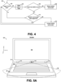
- Figure 4 shows a flow chart of embodiment method 400 for controlling the intensity of power radiated by a transmitter, according to an embodiment of the present invention.
- Method 400 may be implemented by processing system 104.
- step 402 it is determined whether there is a target within the field of view (FoV) of millimeter-wave radar sensor 102. If a target is detected, step 404 is performed. If a target is not detected, step 410 is performed.
- FoV field of view
- the location of the detected target (e.g., a hand) is obtained, e.g., by performing method 300, with respect to the location of a radiation source.
- the target location is obtained in Cartesian coordinates, which is advantageously linear with respect to the range from millimeter-wave radar sensor 102.
- more than one target is detected during step 404.
- step 406 the distance between the location of each of the detected targets and the location of the source is determined. If the distance of at least one detected target is lower than a predetermined threshold (e.g., 6 cm), the power radiated by the radiation source is reduced during step 408. If the distance is larger than the predetermined threshold, step 410 is performed.
- a predetermined threshold e.g. 6 cm
- the radiated power of the radiation source is compared with a target (e.g., optimum) level. If the radiation power is below the target level (e.g., due to a reduction because of the performance of step 408), the power radiated by the radiation source is increased (e.g., to the target level) during step 412.
- a target e.g., optimum
- Method 400 may be implemented in applications having at least one radio transmitter, such as an 4G LTE radio transmitter, 5G NR radio transmitter, or other types of communication transmitters.
- method 400 may be implemented by a mobile device, such as a laptop, smartphone, tablet, etc.
- method 400 may be implemented by a non-mobile device, such as a smart thermostat, a smart TV, etc.
- FIGS 5A and 5B illustrate various views of laptop 500, according to an embodiment of the present invention.
- Laptop 500 includes millimeter-wave radar system 100, radio communication transmitter 504, display 506, bezel 514, keyboard 508, and hinges 510.
- radio communication transmitter 504 is within the field of view 502 of millimeter-wave radar sensor 102.
- a target e.g., a hand typing on keyboard 508
- output of step 406 yes
- the radiation power of radio communication transmitter 504 is reduced.
- some embodiments advantageously may prevent or reduce the risk of injury to the target (e.g., the hand) due to high radiation while maintaining optimum communication quality via radio communication transmitter 504 when the target is near radio communication transmitter 504.
- radio communication transmitter 504 operates according to the 5G NR standard. In some embodiments, radio communication transmitter 504 operates according to a communication protocol different from 5G NR, such as 4G LTE, or future generations of communication protocols, for example.
- a corresponding step 406 may be performed for each detected target.
- all operational receiver antennas 116 are arranged along the x axis, which allows for the identification of 2D coordinates (e.g., x,y) for each target during step 316.
- some operational receiver antennas 116 are arranged along the x axis and some operational receiver antennas 116 are arranged along the z axis (such as 3 receiver antennas 116 arranged in L shape).
- Some such embodiments allow for the identification of 3D coordinates (e.g., x,y,z) for each target during step 316.
- laptop 500 may implement millimeter-wave radar sensor 102 attached or inside hinge 510.
- other locations may be used, such as in bezel 514 (e.g., with field of view 502 designed to cover radio communication transmitter 504 during normal operation), for example.
- millimeter-wave radar sensor 102 may be collocated in the same location as radio communication transmitter 504.
- Figure 6 illustrates mobile device 600, according to an embodiment of the present invention.
- Mobile device 600 includes display 606, bezel 614, millimeter-wave radar system 100, and radio communication transmitter 504.
- radio communication transmitter 504 and millimeter-wave radar sensor 102 are collocated in the same location in bezel 614.
- field of view 604 of radiation power of radio communication transmitter 504 e.g., substantially
- a target e.g., a hand
- some embodiments advantageously may prevent or reduce the risk of injury to the target (e.g., the hand) due to high radiation while maintaining optimum communication quality via radio communication transmitter 504 when the target is near radio communication transmitter 504.
- a corresponding plurality of millimeter-wave radar sensors 102 may be used to perform respective method 400.
- method 300 may be used for human machine interface (HMI).
- HMI human machine interface
- Figure 7 shows a flow chart of embodiment method 700 for detecting the virtual actuation of a button and, in response, triggering a predetermined action, according to an embodiment of the present invention.
- Method 700 may be implemented by processing system 104.
- Method 700 includes steps 702, 404, 706 and 708.
- Step 404 may be implemented in a similar manner as described with respect to Figure 4 .
- step 702 it is determined whether there is a target within the field of view (FoV) of millimeter-wave radar sensor 102, where the field of view of millimeter-wave radar sensor covers the location of a virtual button. If a target is detected, after obtaining the location of the target during step 404, the target location is compared with the location of the virtual button during step 706. If the target is at the location of the virtual button for longer than a predetermined time (e.g., 2 seconds), a predetermined action is triggered during step 708.
- a predetermined time e.g. 2 seconds
- the predetermined action triggered during step 708 includes turning on or off a device or function or changing a parameter of a device (e.g., volume, intensity, etc.), for example.
- step 706 may be performed for the locations of each of the virtual buttons.
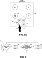
- FIGS 8A and 8B illustrate various views of cooking system 800, according to an embodiment of the present invention.
- Cooking system 800 includes hood 802, projector 804, and stove 806.
- Stove 806 includes top surface 808 and burners 810, 812, 814 and 816.
- FIGS 8C and 8D illustrate a top view of stove 806 during operation, according to an embodiment of the present invention.
- buttons are not displayed on top surface 808.
- projector 804 displays one or more buttons (e.g., 820, 822, 824, and 826) on top surface 808.
- buttons e.g., 820, 822, 824, and 826
- cooking system 800 may perform method 700 (e.g., using processing system 104).
- millimeter-wave radar sensor 102 may be disposed on surface 808. In some embodiments, millimeter-wave radar sensor 102 may be disposed in other places, such as collocated with projector 804, for example.
- method 300 may be used to warn or take action when a target is too close to a predetermined location.
- Figure 9 shows a flow chart of embodiment method 900 for detecting the presence of a target near a predetermined location, according to an embodiment of the present invention.
- Method 900 may be implemented by processing system 104.
- Method 900 includes steps 702, 404, 906 and 908.
- Step 404 may be implemented in a similar manner as described with respect to Figure 4 .
- Step 702 may be implemented in a similar manner as described with respect to Figure 7 .
- a target is detected during step 702
- the target location is compared with a predetermined location (e.g., the location of millimeter-wave radar sensor 102) during step 906. If the target closer than a predetermined distance to the predetermined location, a predetermined action (e.g., warn a user that it is too close to the predetermined location) is triggered during step 908.
- a predetermined location e.g., the location of millimeter-wave radar sensor 102
- FIGS 10A and 10B illustrate various views of laptop 1000, according to an embodiment of the present invention.
- Laptop 1000 includes millimeter-wave radar system 100, display 506, bezel 514, keyboard 508, and hinges 510.
- laptop 1000 may perform method 900 (e.g., using processing system 104).
- head 1002 of a human may be within field of view 502.
- output of step 702 yes
- the location of the head is too close to display 506 (e.g., when the range from millimeter-wave radar sensor 102 is lower than a predetermined threshold)
- an action is taken (908), such as warning the user (e.g., via display 506, using a sound, and/or in another manner) that the user is too close to display 506 (e.g., which may be harmful to the human eyes).
- the brightness of display 506 may be automatically reduced when the target (e.g., hear 1002) is too close to display 506 (such brightness may automatically return to the default brightness once the target is no longer too close to display 506).
- Example 1 A method including: receiving a range-Doppler image (RDI) based on raw data from a radar sensor; performing moving target indication (MTI) filtering on the RDI to generate a first filtered radar image; performing constant false alarm rate (CFAR) detection on the first filtered radar image to generate a second filtered radar image; performing minimum variance distortionless response (MVDR) beamforming on the second filtered radar image to generate a range-angle image (RAI); performing CFAR detection on the RAI to generate a third filtered radar image; generating a point set based on the third filtered radar image; clustering targets of the point set; and tracking at least one of the clustered targets using a Kalman filter.
- RDI range-Doppler image
- MMI moving target indication
- CFAR constant false alarm rate
- MVDR minimum variance distortionless response
- RAI range-angle image
- Example 2 The method of example 1, where each point of the point set includes a signal strength component and a Doppler component.
- Example 3 The method of one of examples 1 or 2, where each point of the point set includes Cartesian coordinates.
- Example 4 The method of one of examples 1 to 3, where cluster the targets includes clustering the targets based on the Cartesian coordinates of each point of the point set.
- Example 5 The method of one of examples 1 to 4, where each point of the point set includes Polar coordinates.
- Example 6 The method of one of examples 1 to 5, further including: transmitting radar signals using the radar sensor; receiving reflected radar signals using the radar sensor; generating the raw data based on the reflected radar signals; and generating the range-Doppler image based on the raw data.
- Example 7 The method of one of examples 1 to 6, where generating the range-Doppler image includes performing a range fast Fourier transform (FFT) on the raw data.
- FFT range fast Fourier transform
- Example 8 The method of one of examples 1 to 7, where the radar sensor includes two receiving antennas.
- Example 9 The method of one of examples 1 to 8, where the radar sensor includes more than two receiving antennas.
- Example 10 The method of one of examples 1 to 9, further including: radiating power with a first intensity using a transmitter of a communication device; and when a first target of the tracked clustered targets is detected within a predetermined distance from the transmitter of the communication device, reducing the radiated power from the first intensity to a second intensity lower than the first intensity.
- Example 11 The method of one of examples 1 to 10, where the radar sensor and the transmitter of the communication device are collocated in the same location.
- Example 12 The method of one of examples 1 to 11, where a field of view of the radar sensor and a field of view of the transmitter of the communication device have a substantially identical angle.
- Example 13 The method of one of examples 1 to 12, where a field of view of the radar sensor covers the transmitter of the communication device.
- Example 14 The method of one of examples 1 to 13, where the communication device operates according to the 5G NR communication standard.
- Example 15 The method of one of examples 1 to 14, where the transmitter of the communication device is located adjacent to a keyboard of a laptop, and where the radar sensor is located in a bezel of a display of the laptop.
- Example 16 The method of one of examples 1 to 15, further including: projecting a button into a first surface; and when a first target of the tracked clustered targets is detected within a predetermined distance from the projected button, causing a first action to be performed.
- Example 17 The method of one of examples 1 to 16, where projecting the button includes projecting the button with a projector located in a hood of a kitchen.
- Example 18 The method of one of examples 1 to 17, where the radar sensor is collocated with the projector.
- Example 19 The method of one of examples 1 to 18, where the radar sensor is located in the first surface.
- Example 20 The method of one of examples 1 to 19, where the radar sensor is located in a bezel of a display, the method further including, when a first target of the tracked clustered targets is detected within a predetermined distance from the display, issue a flag indicative of a user being too close to the display.
- Example 21 The method of one of examples 1 to 20, where a first target of the tracked clustered targets corresponds to a center of a hand of a human.
- a millimeter-wave radar system including: a millimeter-wave radar sensor configured to transmit radar signals and receive reflected radar signals; and a processing system configured to: generate a range-Doppler image (RDI) based on the reflected radar signals, perform moving target indication (MTI) filtering on the RDI to generate a first filtered radar image, perform constant false alarm rate (CFAR) detection on the first filtered radar image to generate a second filtered radar image, perform minimum variance distortionless response (MVDR) beamforming on the second filtered radar image to generate a range-angle image (RAI), perform CFAR detection on the RAI to generate a third filtered radar image, generate a point set based on the third filtered radar image, cluster targets of the point set, and track at least one of the clustered targets using a Kalman filter.
- RDI range-Doppler image
- MMI moving target indication
- CFAR constant false alarm rate
- MVDR minimum variance distortionless response
- RAI range-angle image
- Example 23 A device including: a millimeter-wave radar sensor configured to transmit radar signals and receive reflected radar signals; a communication device including a transmitter configured to radiate power with a first intensity; and a processing system configured to: generate a range-Doppler image (RDI) based on the reflected radar signals, perform moving target indication (MTI) filtering on the RDI to generate a first filtered radar image, perform constant false alarm rate (CFAR) detection on the first filtered radar image to generate a second filtered radar image, perform minimum variance distortionless response (MVDR) beamforming on the second filtered radar image to generate a range-angle image (RAI), perform CFAR detection on the RAI to generate a third filtered radar image, generate a point set based on the third filtered radar image, cluster targets of the point set, track at least one of the clustered targets, and when a first target of the tracked clustered targets is detected within a predetermined distance from the transmitter of the communication device, cause a reduction of the radiated power from the first intensity
Landscapes
- Engineering & Computer Science (AREA)
- Remote Sensing (AREA)
- Radar, Positioning & Navigation (AREA)
- Physics & Mathematics (AREA)
- Computer Networks & Wireless Communication (AREA)
- General Physics & Mathematics (AREA)
- Electromagnetism (AREA)
- Signal Processing (AREA)
- Quality & Reliability (AREA)
- Radar Systems Or Details Thereof (AREA)
Abstract
Description
- The present disclosure relates generally to an electronic system and method, and, in particular embodiments, to a radar-based target tracker.
- Applications in the millimeter-wave frequency regime have gained significant interest in the past few years due to the rapid advancement in low cost semiconductor technologies, such as silicon germanium (SiGe) and fine geometry complementary metal-oxide semiconductor (CMOS) processes. Availability of high-speed bipolar and metal-oxide semiconductor (MOS) transistors has led to a growing demand for integrated circuits for millimeter-wave applications at e.g., 24 GHz, 60 GHz, 77 GHz, and 80 GHz and also beyond 100 GHz. Such applications include, for example, automotive radar systems and multi-gigabit communication systems.
- In some radar systems, the distance between the radar and a target is determined by transmitting a frequency modulated signal, receiving a reflection of the frequency modulated signal (also referred to as the echo), and determining a distance based on a time delay and/or frequency difference between the transmission and reception of the frequency modulated signal. Accordingly, some radar systems include a transmitting antenna for transmitting the radio-frequency (RF) signal, and a receiving antenna for receiving the reflected RF signal, as well as the associated RF circuits used to generate the transmitted signal and to receive the RF signal. In some radar systems, multiple antennas may be used to implement directional beams using phased array techniques. A multiple-input and multiple-output (MIMO) configuration with multiple chipsets can be used to perform coherent and non-coherent signal processing.
- There may be a demand for providing an improved concept for a method and a millimeter-wave radar system.
- Such demand may be satisfied by the subject matter of any of the claims.
- In accordance with an embodiment, a method includes: receiving a range-Doppler image (RDI) based on raw data from a radar sensor; performing moving target indication (MTI) filtering on the RDI to generate a first filtered radar image; performing constant false alarm rate (CFAR) detection on the first filtered radar image to generate a second filtered radar image; performing minimum variance distortionless response (MVDR) beamforming on the second filtered radar image to generate a range-angle image (RAI); performing CFAR detection on the RAI to generate a third filtered radar image; generating a point set based on the third filtered radar image; clustering targets of the point set; and tracking at least one of the clustered targets using a Kalman filter.
- In accordance with an embodiment, a millimeter-wave radar system includes: a millimeter-wave radar sensor configured to transmit radar signals and receive reflected radar signals; and a processing system configured to: generate a range-Doppler image (RDI) based on the reflected radar signals, perform moving target indication (MTI) filtering on the RDI to generate a first filtered radar image, perform constant false alarm rate (CFAR) detection on the first filtered radar image to generate a second filtered radar image, perform minimum variance distortionless response (MVDR) beamforming on the second filtered radar image to generate a range-angle image (RAI), perform CFAR detection on the RAI to generate a third filtered radar image, generate a point set based on the third filtered radar image, cluster targets of the point set, and track at least one of the clustered targets using a Kalman filter.
- In accordance with an embodiment, a device includes: a millimeter-wave radar sensor configured to transmit radar signals and receive reflected radar signals; a communication device including a transmitter configured to radiate power with a first intensity; and a processing system configured to: generate a range-Doppler image (RDI) based on the reflected radar signals, perform moving target indication (MTI) filtering on the RDI to generate a first filtered radar image, perform constant false alarm rate (CFAR) detection on the first filtered radar image to generate a second filtered radar image, perform minimum variance distortionless response (MVDR) beamforming on the second filtered radar image to generate a range-angle image (RAI), perform CFAR detection on the RAI to generate a third filtered radar image, generate a point set based on the third filtered radar image, cluster targets of the point set, track at least one of the clustered targets, and when a first target of the tracked clustered targets is detected within a predetermined distance from the transmitter of the communication device, cause a reduction of the radiated power from the first intensity to a second intensity lower than the first intensity.
- For a more complete understanding of the present invention, and the advantages thereof, reference is now made to the following descriptions taken in conjunction with the accompanying drawings, in which:
-
Figure 1 shows a schematic diagram of a millimeter-wave radar system, according to an embodiment of the present invention; -
Figure 2 shows a sequence of chirps transmitted by the transmitter antenna ofFigure 1 , according to an embodiment of the present invention; -
Figure 3 shows a flow chart of an embodiment method for detecting and tracking short-range targets, according to an embodiment of the present invention; -
Figure 4 shows a flow chart of an embodiment method for controlling the intensity of power radiated by a transmitter, according to an embodiment of the present invention; -
Figures 5A and5B illustrate various views of a laptop, according to an embodiment of the present invention; -
Figure 6 illustrates mobile device 600, according to an embodiment of the present invention; -
Figure 7 shows a flow chart of an embodiment method for detecting the virtual actuation of a button and, in response, triggering a predetermined action, according to an embodiment of the present invention; -
Figures 8A-8D illustrate various views of a cooking system, according to an embodiment of the present invention; -
Figure 9 shows a flow chart of an embodiment method for detecting the presence of a target near a predetermined location, according to an embodiment of the present invention; and -
Figures 10A and 10B illustrate various views of a laptop, according to an embodiment of the present invention. - Corresponding numerals and symbols in different figures generally refer to corresponding parts unless otherwise indicated. The figures are drawn to clearly illustrate the relevant aspects of the preferred embodiments and are not necessarily drawn to scale.
- The making and using of the embodiments disclosed are discussed in detail below. It should be appreciated, however, that the present invention provides many applicable inventive concepts that can be embodied in a wide variety of specific contexts. The specific embodiments discussed are merely illustrative of specific ways to make and use the invention, and do not limit the scope of the invention.
- The description below illustrates the various specific details to provide an in-depth understanding of several example embodiments according to the description. The embodiments may be obtained without one or more of the specific details, or with other methods, components, materials and the like. In other cases, known structures, materials or operations are not shown or described in detail so as not to obscure the different aspects of the embodiments. References to "an embodiment" in this description indicate that a particular configuration, structure or feature described in relation to the embodiment is included in at least one embodiment. Consequently, phrases such as "in one embodiment" that may appear at different points of the present description do not necessarily refer exactly to the same embodiment. Furthermore, specific formations, structures or features may be combined in any appropriate manner in one or more embodiments.
- Embodiments of the present invention will be described in specific contexts, e.g., a radar-based short-range target tracker, which may be used in applications such as safety-related applications and human machine interface (HMI). Some embodiments may be used in other applications.
- In an embodiment of the present invention, a radar processing chain detects and tracks short-range targets. Static targets and clutter are removed by performing moving target indication (MTI) filtering on radar-Doppler images (RDIs). Constant false alarm rate (CFAR) is performed on the filtered RDIs before performing digital beamforming, which may advantageously reduce the computational complexity of the radar processing chain, which may allow for real-time operation.
- Embodiments of the present invention may be used in safety applications, such as by automatically causing the reduction of radiated power by a radio communication transmitter when a human (or a portion of a human) is near the radio communication transmitter and/or by warning a user when the user is too close to a predetermined location. Embodiments of the present invention may also be used in HMI applications, such as for detecting the actuation of virtual buttons.
- A radar, such as a millimeter-wave radar, may be used to detect and track one or more (e.g., short-range) targets. For example,
Figure 1 shows a schematic diagram of millimeter-wave radar system 100, according to an embodiment of the present invention. Millimeter-wave radar system 100 includes millimeter-wave radar sensor 102 andprocessing system 104. - During normal operation, millimeter-
wave radar sensor 102 operates as a frequency-modulated continuous-wave (FMCW) radar sensor and transmits a plurality ofTX radar signals 106, such as chirps, towardsscene 120 using one or more transmitter (TX)antenna 114. Theradar signals 106 are generated using RF andanalog circuits 130. Theradar signals 106 may be, e.g., in the 20 GHz to 122 GHz range. Other frequencies may also be used. - In some embodiments, the field of view of millimeter-
wave radar sensor 102 coveringscene 120 has a short-range, such as below 1 meter, such as within 35 cm. - The objects in
scene 120 may include one or more static or moving objects, such as a surface (e.g., table, countertop, etc.), a keyboard, a wall, and a portion of a human, such as a hand, head, or finger. Other objects may also be present inscene 120. - The
radar signals 106 are reflected by objects inscene 120. Thereflected radar signals 108, which are also referred to as the echo signal, are received by a plurality of receiving (RX) antennas. RF andanalog circuits 130 processes the received reflectedradar signals 108 using, e.g., band-pass filters (BPFs), low-pass filters (LPFs), mixers, low-noise amplifier (LNA), and/or intermediate frequency (IF) amplifiers in ways known in the art to generate an analog signal xouta (t) and xoutb (t) - The analog signal xouta (t) and xoutb (t) are converted to raw digital data xout_dig (n) using analog-to-digital converter (ADC) 112. The raw digital data xout_dig (n) is processed by
processing system 104 to detect one or more targets and their position. In some embodiments,processing system 104 may also be used to track one or more targets inscene 120. - Although
Figure 1 illustrates a radar system with two receiver antennas 116 (antennas - Although
Figure 1 illustrates a radar system with asingle transmitter antenna 114, it is understood that more than onetransmitter antenna 114, such as two or more, may also be used. -
Controller 110 controls one or more circuits of millimeter-wave radar sensor 102, such as RF andanalog circuit 130 and/orADC 112.Controller 110 may be implemented, e.g., as a custom digital or mixed signal circuit, for example.Controller 110 may also be implemented in other ways, such as using a general-purpose processor or controller, for example. In some embodiments,processing system 104 implements a portion or all ofcontroller 110. -
Processing system 104 may be implemented with a general-purpose processor, controller or digital signal processor (DSP) that includes, for example, combinatorial circuits coupled to a memory. In some embodiments,processing system 104 may be implemented as an application specific integrated circuit (ASIC). In some embodiments,processing system 104 may be implemented with an ARM, RISC, or x86 architecture, for example. In some embodiments,processing system 104 may include an artificial intelligence (AI) accelerator. Some embodiments may use a combination of hardware accelerator and software running on a DSP or general-purpose microcontroller. Other implementations are also possible. - In some embodiments, millimeter-
wave radar sensor 102 and a portion or all ofprocessing system 104 may be implemented inside the same integrated circuit (IC). For example, in some embodiments, millimeter-wave radar sensor 102 and a portion or all ofprocessing system 104 may be implemented in respective semiconductor substrates that are integrated in the same package. In other embodiments, millimeter-wave radar sensor 102 and a portion or all ofprocessing system 104 may be implemented in the same monolithic semiconductor substrate. In some embodiments, millimeter-wave radar sensor 102 andprocessing system 104 are implemented in respective integrated circuits. In some embodiments, a plurality of integrated circuits is used to implement millimeter-wave radar sensor 102. In some embodiments, a plurality of integrated circuits is used to implementprocessing system 104. Other implementations are also possible. - As a non-limiting example, RF and
analog circuits 130 may be implemented, e.g., as shown inFigure 1 . During normal operation, voltage-controlled oscillator (VCO) 136 generates radar signals, such as a linear frequency chirps (e.g., from 57 GHz to 64 GHz, or from 76 GHz to 77 GHz), which are transmitted by transmittingantenna 114. TheVCO 136 is controlled byPLL 134, which receives a reference clock signal (e.g., 80 MHz) fromreference oscillator 132.PLL 134 is controlled by a loop that includesfrequency divider 138 andamplifier 140.Amplifier 137 may be used to drive transmittingantenna 114. - The TX radar signals 106 transmitted by transmitting
antenna 114 are reflected by objects inscene 120 and received by receivingantennas antennas antenna 114 usingmixer Amplifiers antennas - Beat signals xIFa (t) xIFb (t) are filtered with respective low-pass filters (LPFs) 148a and 148b and then sampled by
ADC 112.ADC 112 is advantageously capable of sampling the filtered beat signals xouta (t) xoutb (t) with a sampling frequency that is much smaller than the frequency of the signal received by receivingantennas ADC 112, in some embodiments. - The raw digital data xout_dig (n), which in some embodiments include the digitized version of the filtered beat signals xouta (t) and xoutb (t), is (e.g., temporarily) stored, e.g., in matrices of Nc × Ns per receiving antenna 116, where Nc is the number of chirps considered in a frame and Ns is the number of transmit samples per chirp, for further processing by
processing system 104. - In some embodiments,
ADC 112 is a 12-bit ADC with multiple inputs. ADCs with higher resolution, such as 14-bits or higher, or with lower resolution, such as 10-bits, or lower, may also be used. In some embodiments, an ADC per receiver antenna may be used. Other implementations are also possible. -
Figure 2 shows a sequence ofchirps 106 transmitted byTX antenna 114, according to an embodiment of the present invention. As shown byFigure 2 , chirps 106 are organized in a plurality of frames (also referred to as physical frames) and may be implemented as up-chirps. Some embodiments may use down-chirps or a combination of up-chirps and down-chirps, such as up-down chirps and down-up chirps. Other waveform shapes may also be used. - As shown in
Figure 2 , each frame may include a plurality of chirps 106 (also referred to, generally, as pulses). For example, in some embodiments, the number of chirps in a frame is 64. Some embodiments may include more than 64 chirps per frame, such as 96 chirps, 128 chirps, 256 chirps, or more, or less than 64 chirps per frame, such as 32 chirps or less. - In some embodiments, frames are repeated every FT time. In some embodiments, FT time is 50 ms. A different FT time may also be used, such as more than 50 ms, such as 60 ms, 100 ms, 200 ms, or more, or less than 50 ms, such as 45 ms, 40 ms, or less.
- In some embodiments, the FT time is selected such that the time between the beginning of the last chirp of frame n and the beginning of the first chirp of frame n+1 is equal to PRT. Other embodiments may use or result in a different timing.
- The time between chirps of a frame is generally referred to as pulse repetition time (PRT). In some embodiments, the PRT is 5 ms. A different PRT may also be used, such as less than 5 ms, such as 4 ms, 2 ms, 0.5 ms, or less, or more than 5 ms, such as 6 ms, or more.
- The duration of the chirp (from start to finish) is generally referred to as chirp time (CT). In some embodiments, the chirp time may be, e.g., 64 µs. Higher chirp times, such as 128 µs, or higher, may also be used. Lower chirp times, may also be used.
- In some embodiments, the chirp bandwidth may be, e.g., 4 GHz. Higher bandwidth, such as 6 GHz or higher, or lower bandwidth, such as 2 GHz, 1 GHz, or lower, may also be possible.
- In some embodiments, the sampling frequency of millimeter-
wave radar sensor 102 may be, e.g., 1 MHz. Higher sampling frequencies, such as 2 MHz or higher, or lower sampling frequencies, such as 500 kHz or lower, may also be possible. - In some embodiments, the number of samples used to generate a chirp may be, e.g., 64 samples. A higher number of samples, such as 128 samples, or higher, or a lower number of samples, such as 32 samples or lower, may also be used.
-
Figure 3 shows a flow chart ofembodiment method 300 for detecting and tracking short-range targets, according to an embodiment of the present invention.Method 300 may be implemented by processingsystem 104. - During
step 302, a range fast Fourier transform (FFT) is performed on the raw digital data xout_dig (n) (e.g., on data from each receiving channel, e.g., from each receiving antenna 116). For example, in some embodiments, a windowed FFT having a length of a chirp (e.g., 106) is calculated for each of a predetermined number of chirps (e.g., all chirps) in a frame. The result of the range FFT is an indication of energy distribution across ranges for each chirp. - During
step 304, a Doppler FFT is performed on the out range FFT data (e.g., for each receiving antenna 116) generated duringstep 302. For example, in some embodiments, an FFT is calculated across each range bin over a number of consecutive periods to extract Doppler information. The result ofstep 304 are range Doppler maps (also known are range-Doppler images or RDIs) for each of the receiving channels (e.g., for each receiving antenna 116). - During
step 306, two-dimensional (2D) moving target indication (MTI) filtering is applied to each RDI to generate first filtered images. In some embodiments, performing MTI filtering serves to discriminate a target against the clutter. For example, in some embodiments, after MTI filtering is performed on the RDIs, only targets with high motion are retained as their energy varies across Doppler images. Thus, in some embodiments, after 2D MTI filtering, a target (e.g., a hand) may be identifiable in the filtered RDIs while information about the background (e.g., keyboard, surface, etc.) may be partially or fully removed from the filtered RDIs. In some embodiments, the 2D MTI filter is implemented as a first order finite impulse response (FIR) filter. - During
step 308, target detection is performed using constant false alarm rate (CFAR), such as ordered-statistic (OS) CFAR (OS-CFAR) on the filtered RDIs generated duringstep 306 to generated second filtered images (also referred to as RD masked detection images). Duringstep 308, the CFAR detector generates a detection image in which, e.g., "ones" represent targets and "zeros" represent non-targets based on the power levels of the RDI when compared with a, e.g., predetermined threshold. The RD detection image operates as a mask and is multiplied by the original RDI (output of step 306) to obtain an RD masked image (at the output of step 308) in which only details of the detected targets are non-zero. - In some embodiments, detection of targets during
step 308 is advantageously enabled by the relatively high signal-to-noise ratio (SNR) of moving targets due to the short-range field of view of millimeter-wave radar sensor 102. - In some embodiments, the performance of
steps - In some embodiments, performing target detecting on the RDIs before performing digital beamforming advantageously reduced computational complexity and allows for real-time operation.
- During
step 310, (e.g., 1D) digital beamforming (e.g., 1D Capon) is applied to estimate angle from the data across virtual channels from the antenna array configuration for each range that has passedstep 308 to generate 2D range-angle image (RAI). - During
step 312, target detection is performed using CFAR (e.g., OS-CFAR) on the RAI detection images generated duringstep 310 to generate third filtered images (also referred to as RA masked detection images). Duringstep 312, the CFAR detector generates a detection image in which, e.g., "ones" represent targets and "zeros" represent non-targets based on the power levels of the RAI when compared with a, e.g., predetermined threshold. The RA detection image operates as a mask and is multiplied by the original RAI (output of step 310) to obtain an RA masked detection image (at the output of step 312) in which only details of the detected targets are non-zero. - During
step 314, a conversion from Polar coordinates to Cartesian coordinates is performed. In some embodiments,step 314 is omitted. - During
step 316, a set of detection points is generated. In some embodiments, each detection point includes: 2D coordinates, a signal strength value (indicative of the signal strength of target located at the 2D coordinates), and a Doppler value (indicative of the level of movement of the target at the 2D coordinates). In some embodiments, the 2D coordinates are Cartesian coordinates (e.g., x, y) (e.g., ifstep 314 is performed). In some embodiments, the 2D coordinates are Polar coordinates (e.g., range and angle) (e.g., ifstep 314 is not performed). - In some embodiments, such as in embodiments in which all receiving antennas are aligned in the same (e.g., horizontal) axis, each point of the set of detection points include 2D coordinates. In some embodiments, such as in embodiments in which the receiving antennas are arranged in an L shape, each point of the set of detection points include 3D coordinates.
- During
step 318, the points (targets) of the set of detection points are clustered, e.g., using a density-based spatial clustering of applications with noise (DBSCAN) algorithm to associate points (targets) to clusters. The output of DBSCAN is one or more groupings (clusters) of detected points, so that each grouping is associated with a respective target. - In some embodiments, each clustered target is represented as a single target having a point location, which may be the centroid of the cluster. For example, in some embodiments, a human hand may appear as a collection of targets before
step 318. Afterstep 318, a single point (e.g., corresponding to a geometric center of the hand) is used to represent the human hand. - In some embodiments, using Cartesian coordinates (e.g., by performing step 314) advantageously allows for an easier (e.g., less computationally expensive) implementation of the clustering step (318) since Cartesian coordinates are advantageously linear irrespective of the range. For example, in some embodiments, the same threshold (e.g., clustering points within 6 cm) may be performed to points near millimeter-
wave radar sensor 102 and to points far from millimeter-wave radar sensor 102. - During
step 320, the detected clusters are associated to respective tracks, e.g., using a probabilistic data association filter (PDAF) or nearest neighbor approach. In some embodiments, a (e.g., unscented) Kalman filter is used to filter and smoothen the tracks. In some embodiments, all features of the clusters (e.g., coordinates, signal strength value, and Doppler value) are tracked and filtered using the Kalman filter. In some embodiments, the Kalman filter may only track a subset of the features of the cluster (e.g., just the coordinates, such as (x,y)). The Kalman filter may be implemented in any way known in the art. - During
step 322, visualization of the clusters (e.g., in a static manner, in real time, or over time) may be displayed, e.g., in a display. - Compared to camera-based target detection and tracking, target detection and tracking based on radar measurements can have some advantages such as: invariant to illumination conditions and preserving privacy.
- Compared to Lidar-based solution target detection, target detection and tracking based on radar measurements can have some advantages such as being less expensive.
- In some embodiments,
method 300 may be performed to detect the presence of a human or a portion of human near a radiation source and reduce the power emitted by the radiation source in response to the detection of the presence of the human or portion of the human near the radiation source (e.g., to reduce or minimize the chance of injury to the human or portion of the human). For example, radiated power of a 5G NR transmitter may be focused on a narrow zone, which can cause health issues due to a high specific absorption rate (SAR) level. It may be desirable for communication devices, such as communication devices operating according to the 5G NR communication standard, to maintain the radiated power level low when a human or a portion of a human is near the radiation source to keep the SAR level below acceptable levels (which may be dictated by governmental organizations, such as the federal communication commission (FCC), and other global safety guidelines). -
Figure 4 shows a flow chart ofembodiment method 400 for controlling the intensity of power radiated by a transmitter, according to an embodiment of the present invention.Method 400 may be implemented by processingsystem 104. - During
step 402, it is determined whether there is a target within the field of view (FoV) of millimeter-wave radar sensor 102. If a target is detected,step 404 is performed. If a target is not detected,step 410 is performed. - During
step 404, the location of the detected target (e.g., a hand) is obtained, e.g., by performingmethod 300, with respect to the location of a radiation source. In some embodiments, the target location is obtained in Cartesian coordinates, which is advantageously linear with respect to the range from millimeter-wave radar sensor 102. In some embodiments, more than one target is detected duringstep 404. - During
step 406, the distance between the location of each of the detected targets and the location of the source is determined. If the distance of at least one detected target is lower than a predetermined threshold (e.g., 6 cm), the power radiated by the radiation source is reduced duringstep 408. If the distance is larger than the predetermined threshold,step 410 is performed. - During
step 410, the radiated power of the radiation source is compared with a target (e.g., optimum) level. If the radiation power is below the target level (e.g., due to a reduction because of the performance of step 408), the power radiated by the radiation source is increased (e.g., to the target level) duringstep 412. -
Method 400 may be implemented in applications having at least one radio transmitter, such as an 4G LTE radio transmitter, 5G NR radio transmitter, or other types of communication transmitters. For example, in some embodiment,method 400 may be implemented by a mobile device, such as a laptop, smartphone, tablet, etc. In some embodiments,method 400 may be implemented by a non-mobile device, such as a smart thermostat, a smart TV, etc. -
Figures 5A and5B illustrate various views oflaptop 500, according to an embodiment of the present invention.Laptop 500 includes millimeter-wave radar system 100,radio communication transmitter 504,display 506,bezel 514,keyboard 508, and hinges 510. As shown inFigures 5A and5B ,radio communication transmitter 504 is within the field ofview 502 of millimeter-wave radar sensor 102. - During normal operation,
laptop 500 may perform method 400 (e.g., using processing system 104). For example, when a target (e.g., a hand typing on keyboard 508) is detected near radio communication transmitter 504 (output ofstep 406 = yes), the radiation power ofradio communication transmitter 504 is reduced. By reducing the magnitude of power radiated byradio communication transmitter 504 when the target (e.g., the hand) is nearradio communication transmitter 504, some embodiments advantageously may prevent or reduce the risk of injury to the target (e.g., the hand) due to high radiation while maintaining optimum communication quality viaradio communication transmitter 504 when the target is nearradio communication transmitter 504. - In some embodiments,
radio communication transmitter 504 operates according to the 5G NR standard. In some embodiments,radio communication transmitter 504 operates according to a communication protocol different from 5G NR, such as 4G LTE, or future generations of communication protocols, for example. - In embodiments that include a plurality of
radio communication transmitters 504, acorresponding step 406 may be performed for each detected target. - In some embodiments, such as in
laptop 500, all operational receiver antennas 116 are arranged along the x axis, which allows for the identification of 2D coordinates (e.g., x,y) for each target duringstep 316. In some embodiments, some operational receiver antennas 116 are arranged along the x axis and some operational receiver antennas 116 are arranged along the z axis (such as 3 receiver antennas 116 arranged in L shape). Some such embodiments allow for the identification of 3D coordinates (e.g., x,y,z) for each target duringstep 316. - As shown in
Figure 5 ,laptop 500 may implement millimeter-wave radar sensor 102 attached orinside hinge 510. In some embodiments, other locations may be used, such as in bezel 514 (e.g., with field ofview 502 designed to coverradio communication transmitter 504 during normal operation), for example. - In some
embodiments implementing method 400, millimeter-wave radar sensor 102 may be collocated in the same location asradio communication transmitter 504. For example,Figure 6 illustrates mobile device 600, according to an embodiment of the present invention. Mobile device 600 includesdisplay 606,bezel 614, millimeter-wave radar system 100, andradio communication transmitter 504. - As shown in
Figure 6 ,radio communication transmitter 504 and millimeter-wave radar sensor 102 are collocated in the same location inbezel 614. As also shown inFigure 6 , field ofview 604 of radiation power of radio communication transmitter 504 (e.g., substantially) overlaps with field ofview 502 of millimeter-wave radar sensor 102 in the short-range region (and may have substantially identical angle). - During normal operation, mobile device 600 may perform method 400 (e.g., using processing system 104). For example, since fields of
view 502 and 604 (e.g., substantially) overlap in the short range (e.g., at a range equal to the predetermined range, or lower), a target detected in field ofview 502 near millimeter-wave radar sensor 102 (at short range) is also nearradio communication transmitter 504. Thus, in some embodiments, when a target (e.g., a hand) is detected in the field ofview 502 at a range equal to a predetermined range or lower (output ofstep 406 = yes), the radiation power ofradio communication transmitter 504 is reduced. By reducing the magnitude of power radiated byradio communication transmitter 504 when the target (e.g., the hand) is nearradio communication transmitter 504, some embodiments advantageously may prevent or reduce the risk of injury to the target (e.g., the hand) due to high radiation while maintaining optimum communication quality viaradio communication transmitter 504 when the target is nearradio communication transmitter 504. - In embodiments that include a plurality of
radio communication transmitters 504, a corresponding plurality of millimeter-wave radar sensors 102 may be used to performrespective method 400. - In some embodiments,
method 300 may be used for human machine interface (HMI). For example,Figure 7 shows a flow chart ofembodiment method 700 for detecting the virtual actuation of a button and, in response, triggering a predetermined action, according to an embodiment of the present invention.Method 700 may be implemented by processingsystem 104. -
Method 700 includessteps Figure 4 . - During
step 702, it is determined whether there is a target within the field of view (FoV) of millimeter-wave radar sensor 102, where the field of view of millimeter-wave radar sensor covers the location of a virtual button. If a target is detected, after obtaining the location of the target duringstep 404, the target location is compared with the location of the virtual button duringstep 706. If the target is at the location of the virtual button for longer than a predetermined time (e.g., 2 seconds), a predetermined action is triggered duringstep 708. - In some embodiments, the predetermined action triggered during
step 708 includes turning on or off a device or function or changing a parameter of a device (e.g., volume, intensity, etc.), for example. - In embodiments having multiple virtual buttons,
step 706 may be performed for the locations of each of the virtual buttons. -
Figures 8A and8B illustrate various views ofcooking system 800, according to an embodiment of the present invention.Cooking system 800 includeshood 802,projector 804, andstove 806.Stove 806 includestop surface 808 andburners -
Figures 8C and8D illustrate a top view ofstove 806 during operation, according to an embodiment of the present invention. - As shown in
Figures 8A and8B , in an off mode of operation, virtual buttons are not displayed ontop surface 808. As shown inFigures 8C and8D , in an on mode of operation,projector 804 displays one or more buttons (e.g., 820, 822, 824, and 826) ontop surface 808. During the on mode of operation,cooking system 800 may perform method 700 (e.g., using processing system 104). For example, as illustrated inFigure 8D , when hand/finger 840 is detect overbutton 824 for longer than a predetermined time (output ofstep 706 = yes), thecorresponding burner 814 is turned on. - As shown in
Figures 8A-8D , in some embodiments, millimeter-wave radar sensor 102 may be disposed onsurface 808. In some embodiments, millimeter-wave radar sensor 102 may be disposed in other places, such as collocated withprojector 804, for example. - In some embodiments,
method 300 may be used to warn or take action when a target is too close to a predetermined location. For example,Figure 9 shows a flow chart ofembodiment method 900 for detecting the presence of a target near a predetermined location, according to an embodiment of the present invention.Method 900 may be implemented by processingsystem 104. -
Method 900 includessteps Figure 4 . Step 702 may be implemented in a similar manner as described with respect toFigure 7 . - If a target is detected during
step 702, after obtaining the location of the target duringstep 404, the target location is compared with a predetermined location (e.g., the location of millimeter-wave radar sensor 102) duringstep 906. If the target closer than a predetermined distance to the predetermined location, a predetermined action (e.g., warn a user that it is too close to the predetermined location) is triggered duringstep 908. -
Figures 10A and 10B illustrate various views oflaptop 1000, according to an embodiment of the present invention.Laptop 1000 includes millimeter-wave radar system 100,display 506,bezel 514,keyboard 508, and hinges 510. - During normal operation,
laptop 1000 may perform method 900 (e.g., using processing system 104). For example, as illustrated inFigure 10B ,head 1002 of a human may be within field ofview 502. Whenhead 1002 is within the field of view 502 (output ofstep 702 = yes) if the location of the head is too close to display 506 (e.g., when the range from millimeter-wave radar sensor 102 is lower than a predetermined threshold), an action is taken (908), such as warning the user (e.g., viadisplay 506, using a sound, and/or in another manner) that the user is too close to display 506 (e.g., which may be harmful to the human eyes). In some embodiments, the brightness ofdisplay 506 may be automatically reduced when the target (e.g., hear 1002) is too close to display 506 (such brightness may automatically return to the default brightness once the target is no longer too close to display 506). - Example embodiments of the present invention are summarized here. Other embodiments can also be understood from the entirety of the specification and the claims filed herein.
- Example 1. A method including: receiving a range-Doppler image (RDI) based on raw data from a radar sensor; performing moving target indication (MTI) filtering on the RDI to generate a first filtered radar image; performing constant false alarm rate (CFAR) detection on the first filtered radar image to generate a second filtered radar image; performing minimum variance distortionless response (MVDR) beamforming on the second filtered radar image to generate a range-angle image (RAI); performing CFAR detection on the RAI to generate a third filtered radar image; generating a point set based on the third filtered radar image; clustering targets of the point set; and tracking at least one of the clustered targets using a Kalman filter.
- Example 2. The method of example 1, where each point of the point set includes a signal strength component and a Doppler component.
- Example 3. The method of one of examples 1 or 2, where each point of the point set includes Cartesian coordinates.
- Example 4. The method of one of examples 1 to 3, where cluster the targets includes clustering the targets based on the Cartesian coordinates of each point of the point set.
- Example 5. The method of one of examples 1 to 4, where each point of the point set includes Polar coordinates.
- Example 6. The method of one of examples 1 to 5, further including: transmitting radar signals using the radar sensor; receiving reflected radar signals using the radar sensor; generating the raw data based on the reflected radar signals; and generating the range-Doppler image based on the raw data.
- Example 7. The method of one of examples 1 to 6, where generating the range-Doppler image includes performing a range fast Fourier transform (FFT) on the raw data.
- Example 8. The method of one of examples 1 to 7, where the radar sensor includes two receiving antennas.
- Example 9. The method of one of examples 1 to 8, where the radar sensor includes more than two receiving antennas.
- Example 10. The method of one of examples 1 to 9, further including: radiating power with a first intensity using a transmitter of a communication device; and when a first target of the tracked clustered targets is detected within a predetermined distance from the transmitter of the communication device, reducing the radiated power from the first intensity to a second intensity lower than the first intensity.
- Example 11. The method of one of examples 1 to 10, where the radar sensor and the transmitter of the communication device are collocated in the same location.
- Example 12. The method of one of examples 1 to 11, where a field of view of the radar sensor and a field of view of the transmitter of the communication device have a substantially identical angle.
- Example 13. The method of one of examples 1 to 12, where a field of view of the radar sensor covers the transmitter of the communication device.
- Example 14. The method of one of examples 1 to 13, where the communication device operates according to the 5G NR communication standard.
- Example 15. The method of one of examples 1 to 14, where the transmitter of the communication device is located adjacent to a keyboard of a laptop, and where the radar sensor is located in a bezel of a display of the laptop.
- Example 16. The method of one of examples 1 to 15, further including: projecting a button into a first surface; and when a first target of the tracked clustered targets is detected within a predetermined distance from the projected button, causing a first action to be performed.
- Example 17. The method of one of examples 1 to 16, where projecting the button includes projecting the button with a projector located in a hood of a kitchen.
- Example 18. The method of one of examples 1 to 17, where the radar sensor is collocated with the projector.
- Example 19. The method of one of examples 1 to 18, where the radar sensor is located in the first surface.
- Example 20. The method of one of examples 1 to 19, where the radar sensor is located in a bezel of a display, the method further including, when a first target of the tracked clustered targets is detected within a predetermined distance from the display, issue a flag indicative of a user being too close to the display.
- Example 21. The method of one of examples 1 to 20, where a first target of the tracked clustered targets corresponds to a center of a hand of a human.
- Example 22. A millimeter-wave radar system including: a millimeter-wave radar sensor configured to transmit radar signals and receive reflected radar signals; and a processing system configured to: generate a range-Doppler image (RDI) based on the reflected radar signals, perform moving target indication (MTI) filtering on the RDI to generate a first filtered radar image, perform constant false alarm rate (CFAR) detection on the first filtered radar image to generate a second filtered radar image, perform minimum variance distortionless response (MVDR) beamforming on the second filtered radar image to generate a range-angle image (RAI), perform CFAR detection on the RAI to generate a third filtered radar image, generate a point set based on the third filtered radar image, cluster targets of the point set, and track at least one of the clustered targets using a Kalman filter.
- Example 23. A device including: a millimeter-wave radar sensor configured to transmit radar signals and receive reflected radar signals; a communication device including a transmitter configured to radiate power with a first intensity; and a processing system configured to: generate a range-Doppler image (RDI) based on the reflected radar signals, perform moving target indication (MTI) filtering on the RDI to generate a first filtered radar image, perform constant false alarm rate (CFAR) detection on the first filtered radar image to generate a second filtered radar image, perform minimum variance distortionless response (MVDR) beamforming on the second filtered radar image to generate a range-angle image (RAI), perform CFAR detection on the RAI to generate a third filtered radar image, generate a point set based on the third filtered radar image, cluster targets of the point set, track at least one of the clustered targets, and when a first target of the tracked clustered targets is detected within a predetermined distance from the transmitter of the communication device, cause a reduction of the radiated power from the first intensity to a second intensity lower than the first intensity.
- While this invention has been described with reference to illustrative embodiments, this description is not intended to be construed in a limiting sense. Various modifications and combinations of the illustrative embodiments, as well as other embodiments of the invention, will be apparent to persons skilled in the art upon reference to the description. It is therefore intended that the appended claims encompass any such modifications or embodiments.
Claims (15)
- A method comprising:receiving a range-Doppler image (RDI) based on raw data from a radar sensor;performing moving target indication (MTI) filtering on the RDI to generate a first filtered radar image;performing constant false alarm rate (CFAR) detection on the first filtered radar image to generate a second filtered radar image;performing minimum variance distortionless response (MVDR) beamforming on the second filtered radar image to generate a range-angle image (RAI);performing CFAR detection on the RAI to generate a third filtered radar image;generating a point set based on the third filtered radar image;clustering targets of the point set; andtracking at least one of the clustered targets using a Kalman filter.
- The method of claim 1, wherein each point of the point set comprises a signal strength component and a Doppler component.
- The method of claim 1 or 2, wherein each point of the point set comprises Cartesian coordinates.
- The method of claim 3, wherein cluster the targets comprises clustering the targets based on the Cartesian coordinates of each point of the point set.
- The method of any of claims 2 to 4, wherein each point of the point set comprises Polar coordinates.
- The method of any of the preceding claims, further comprising:transmitting radar signals using the radar sensor;receiving reflected radar signals using the radar sensor;generating the raw data based on the reflected radar signals; andgenerating the range-Doppler image based on the raw data.
- The method of claim 6, wherein generating the range-Doppler image comprises performing a range fast Fourier transform (FFT) on the raw data.
- The method of any of the preceding claims, wherein the radar sensor comprises two receiving antennas.
- The method of any of the preceding claims, wherein the radar sensor comprises more than two receiving antennas.
- The method of any of the preceding claims, further comprising:radiating power with a first intensity using a transmitter of a communication device; andwhen a first target of the tracked clustered targets is detected within a predetermined distance from the transmitter of the communication device, reducing the radiated power from the first intensity to a second intensity lower than the first intensity.
- The method of claim 10, wherein the radar sensor and the transmitter of the communication device are collocated in the same location.
- The method of claim 11, wherein a field of view of the radar sensor and a field of view of the transmitter of the communication device have a substantially identical angle.
- The method of any of claims 10 to 12, wherein a field of view of the radar sensor covers the transmitter of the communication device.
- The method of any of claims 10 to 13, wherein the communication device operates according to the 5G NR communication standard.
- A millimeter-wave radar system comprising:a millimeter-wave radar sensor configured to transmit radar signals and receive reflected radar signals; anda processing system configured to:generate a range-Doppler image (RDI) based on the reflected radar signals,perform moving target indication (MTI) filtering on the RDI to generate a first filtered radar image,perform constant false alarm rate (CFAR) detection on the first filtered radar image to generate a second filtered radar image,perform minimum variance distortionless response (MVDR) beamforming on the second filtered radar image to generate a range-angle image (RAI),perform CFAR detection on the RAI to generate a third filtered radar image,generate a point set based on the third filtered radar image,cluster targets of the point set, andtrack at least one of the clustered targets using a Kalman filter.
Applications Claiming Priority (1)
| Application Number | Priority Date | Filing Date | Title |
|---|---|---|---|
| US17/869,572 US12399271B2 (en) | 2022-07-20 | 2022-07-20 | Radar-based target tracker |
Publications (2)
| Publication Number | Publication Date |
|---|---|
| EP4310533A2 true EP4310533A2 (en) | 2024-01-24 |
| EP4310533A3 EP4310533A3 (en) | 2024-03-20 |
Family
ID=87426590
Family Applications (1)
| Application Number | Title | Priority Date | Filing Date |
|---|---|---|---|
| EP23186695.5A Pending EP4310533A3 (en) | 2022-07-20 | 2023-07-20 | Radar-based target tracker |
Country Status (3)
| Country | Link |
|---|---|
| US (1) | US12399271B2 (en) |
| EP (1) | EP4310533A3 (en) |
| CN (1) | CN117434530A (en) |
Families Citing this family (1)
| Publication number | Priority date | Publication date | Assignee | Title |
|---|---|---|---|---|
| EP4357810B1 (en) * | 2022-10-19 | 2024-11-27 | Axis AB | Systems and method for adaptive radar frame filtering |
Family Cites Families (141)
| Publication number | Priority date | Publication date | Assignee | Title |
|---|---|---|---|---|
| US4241347A (en) | 1978-06-28 | 1980-12-23 | International Telephone And Telegraph Corporation | PRC/FM CW Radar system |
| GB2247799A (en) | 1990-09-04 | 1992-03-11 | Gec Ferranti Defence Syst | Radar based navigation aid |
| US5061934A (en) * | 1990-11-09 | 1991-10-29 | The United States Of America As Represented By The Secretary Of The Air Force | Hybrid clutter cancellation method and system for improved radar performance |
| US6147572A (en) | 1998-07-15 | 2000-11-14 | Lucent Technologies, Inc. | Filter including a microstrip antenna and a frequency selective surface |
| JP3393204B2 (en) | 1999-10-06 | 2003-04-07 | 株式会社ホンダエレシス | Multi-beam radar device |
| ATE403166T1 (en) | 2000-06-06 | 2008-08-15 | Altratek Inc | SENSOR SYSTEM AND METHOD FOR DETECTING AND TRACKING TARGETS |
| DE10037099A1 (en) | 2000-07-28 | 2002-02-07 | Wienand Hans Theo | Personenzählvorrichtung |
| JP3680029B2 (en) | 2001-08-08 | 2005-08-10 | 三菱重工業株式会社 | Vapor growth method and vapor growth apparatus for metal thin film |
| US7176506B2 (en) | 2001-08-28 | 2007-02-13 | Tessera, Inc. | High frequency chip packages with connecting elements |
| US7948769B2 (en) | 2007-09-27 | 2011-05-24 | Hemisphere Gps Llc | Tightly-coupled PCB GNSS circuit and manufacturing method |
| KR100477647B1 (en) | 2002-06-01 | 2005-03-23 | 삼성전자주식회사 | Motion correction apparatus for image and method thereof |
| US6963259B2 (en) | 2002-06-27 | 2005-11-08 | Harris Corporation | High efficiency resonant line |
| JP3833606B2 (en) | 2002-12-19 | 2006-10-18 | 三菱電機株式会社 | In-vehicle radar system |
| US7119745B2 (en) | 2004-06-30 | 2006-10-10 | International Business Machines Corporation | Apparatus and method for constructing and packaging printed antenna devices |
| WO2006017265A2 (en) | 2004-07-12 | 2006-02-16 | Signal-Labs, Inc. | System and method for detection and tracking of targets |
| US7057564B2 (en) | 2004-08-31 | 2006-06-06 | Freescale Semiconductor, Inc. | Multilayer cavity slot antenna |
| US7615856B2 (en) | 2004-09-01 | 2009-11-10 | Sanyo Electric Co., Ltd. | Integrated antenna type circuit apparatus |
| US7692684B2 (en) | 2004-09-27 | 2010-04-06 | Point Grey Research Inc. | People counting systems and methods |
| JP2006234513A (en) | 2005-02-23 | 2006-09-07 | Toyota Central Res & Dev Lab Inc | Obstacle detection device |
| US8066642B1 (en) | 2005-05-03 | 2011-11-29 | Sonosite, Inc. | Systems and methods for ultrasound beam forming data control |
| US7596241B2 (en) | 2005-06-30 | 2009-09-29 | General Electric Company | System and method for automatic person counting and detection of specific events |
| US8228382B2 (en) | 2005-11-05 | 2012-07-24 | Ram Pattikonda | System and method for counting people |
| EP1791277A1 (en) | 2005-11-28 | 2007-05-30 | Siemens Aktiengesellschaft | Method and apparatus for transmission path calibration of an antenna system |
| US20070210959A1 (en) | 2006-03-07 | 2007-09-13 | Massachusetts Institute Of Technology | Multi-beam tile array module for phased array systems |
| WO2008094172A2 (en) | 2006-06-01 | 2008-08-07 | University Of Florida Research Foundation, Inc. | Radar microsensor for detection, tracking, and classification |
| US7873326B2 (en) | 2006-07-11 | 2011-01-18 | Mojix, Inc. | RFID beam forming system |
| DE102006032539A1 (en) | 2006-07-13 | 2008-01-17 | Robert Bosch Gmbh | FMCW radar sensor |
| US7889147B2 (en) | 2007-02-23 | 2011-02-15 | Northrop Grumman Systems Corporation | Modular active phased array |
| US7525474B2 (en) | 2007-03-30 | 2009-04-28 | Honeywell International Inc. | Integrated distance measuring equipment and transponder system and method |
| US7675465B2 (en) | 2007-05-22 | 2010-03-09 | Sibeam, Inc. | Surface mountable integrated circuit packaging scheme |
| US8237259B2 (en) | 2007-06-13 | 2012-08-07 | Infineon Technologies Ag | Embedded chip package |
| JP4415040B2 (en) | 2007-09-18 | 2010-02-17 | 三菱電機株式会社 | Radar equipment |
| US7880677B2 (en) | 2007-12-12 | 2011-02-01 | Broadcom Corporation | Method and system for a phased array antenna embedded in an integrated circuit package |
| US8134425B2 (en) | 2007-12-13 | 2012-03-13 | Broadcom Corporation | Method and system for filters embedded in an integrated circuit package |
| JP4861303B2 (en) | 2007-12-27 | 2012-01-25 | 株式会社日立製作所 | Radar sensor |
| JP2011529181A (en) | 2008-07-24 | 2011-12-01 | コーニンクレッカ フィリップス エレクトロニクス エヌ ヴィ | Distance measurement |
| DE102008054570A1 (en) | 2008-12-12 | 2010-06-17 | Robert Bosch Gmbh | FMCW radar sensor for motor vehicles |
| WO2010092438A1 (en) | 2009-02-13 | 2010-08-19 | Freescale Semiconductor, Inc. | Integrated circuit comprising frequency generation circuitry for controlling a frequency source |
| US20100207805A1 (en) | 2009-02-19 | 2010-08-19 | Agd Systems Limited | Obtaining an indication of a number of moving objects passing speed detection apparatus |
| EP2629113B1 (en) | 2009-04-06 | 2017-04-26 | Conti Temic microelectronic GmbH | Radar system having arrangements and method for decoupling transmission and reception signals and for suppressing interferences |
| CN201438747U (en) | 2009-05-18 | 2010-04-14 | 幻音科技(深圳)有限公司 | earphones |
| CN101585361A (en) | 2009-05-25 | 2009-11-25 | 郭文艺 | Anti-collision and lane-departure-prevention control device for automobile |
| US8861328B2 (en) | 2009-06-17 | 2014-10-14 | Optis Cellular Technology, Llc | Method for antenna calibration in a wideband communication system |
| WO2011004135A1 (en) | 2009-07-07 | 2011-01-13 | Elliptic Laboratories As | Control using movements |
| US9229102B1 (en) | 2009-12-18 | 2016-01-05 | L-3 Communications Security And Detection Systems, Inc. | Detection of movable objects |
| DE102009055262A1 (en) | 2009-12-23 | 2011-06-30 | Endress + Hauser GmbH + Co. KG, 79689 | Method for determining and monitoring the level of a medium in a container according to a transit time measurement method |
| CN102893173B (en) | 2010-03-05 | 2014-12-03 | 温莎大学 | Radar system and method of making the same |
| US8725085B2 (en) | 2010-06-03 | 2014-05-13 | Broadcom Corporation | RF front-end module |
| US9569003B2 (en) | 2010-09-30 | 2017-02-14 | Broadcom Corporation | Portable computing device including a three-dimensional touch screen |
| JP5549560B2 (en) | 2010-11-26 | 2014-07-16 | 富士通株式会社 | FM-CW radar device and pairing method |
| JP2012168156A (en) | 2011-02-11 | 2012-09-06 | National Univ Corp Shizuoka Univ | Multi-beam type radar apparatus for on-vehicle use, multi-beam type radar method and multi-beam type radar program |
| US8988299B2 (en) | 2011-02-17 | 2015-03-24 | International Business Machines Corporation | Integrated antenna for RFIC package applications |
| US20120280900A1 (en) | 2011-05-06 | 2012-11-08 | Nokia Corporation | Gesture recognition using plural sensors |
| DE102011100907A1 (en) | 2011-05-09 | 2012-01-12 | Daimler Ag | Device for determining road condition of roadway located in front of vehicle, comprises imaging sensor for detecting road surface, and evaluation unit for evaluation of image data |
| DE102011075725A1 (en) | 2011-05-12 | 2012-11-15 | Robert Bosch Gmbh | Method for recognizing gestures |
| US8860532B2 (en) | 2011-05-20 | 2014-10-14 | University Of Central Florida Research Foundation, Inc. | Integrated cavity filter/antenna system |
| US9183686B2 (en) | 2011-07-12 | 2015-11-10 | Tyco Fire & Security Gmbh | Method and system for people counting using passive infrared detectors |
| US9705204B2 (en) | 2011-10-20 | 2017-07-11 | Keyssa, Inc. | Low-profile wireless connectors |
| CN104094194A (en) | 2011-12-09 | 2014-10-08 | 诺基亚公司 | Method and apparatus for identifying a gesture based upon fusion of multiple sensor signals |
| US9202105B1 (en) | 2012-01-13 | 2015-12-01 | Amazon Technologies, Inc. | Image analysis for user authentication |
| EP2842384A4 (en) * | 2012-04-26 | 2015-12-16 | Propagation Res Associates Inc | METHOD AND SYSTEM FOR USING ORTHOGONAL SPATIAL PROJECTIONS TO MITIGATE PARASITING |
| CN102788969B (en) | 2012-07-04 | 2015-01-28 | 中国人民解放军海军航空工程学院 | Sea surface micromotion target detection and feature extraction method based on short-time fractional Fourier transform |
| US9678573B2 (en) | 2012-07-30 | 2017-06-13 | Microsoft Technology Licensing, Llc | Interaction with devices based on user state |
| US20140070994A1 (en) | 2012-09-13 | 2014-03-13 | Toyota Motor Engineering & Manufacturing North America, Inc. | 3d short range detection with phased array radar |
| US9196951B2 (en) | 2012-11-26 | 2015-11-24 | International Business Machines Corporation | Millimeter-wave radio frequency integrated circuit packages with integrated antennas |
| CN102967854B (en) | 2012-12-07 | 2014-08-13 | 中国人民解放军海军航空工程学院 | Multi-fractal detection method of targets in FRFT (Fractional Fourier Transformation) domain sea clutter |
| TWI553721B (en) | 2012-12-26 | 2016-10-11 | 日立化成股份有限公司 | Expansion method and method of manufacturing semiconductor device |
| US8836596B2 (en) | 2013-01-15 | 2014-09-16 | Cubic Corporation | Filter antenna |
| US9413079B2 (en) | 2013-03-13 | 2016-08-09 | Intel Corporation | Single-package phased array module with interleaved sub-arrays |
| KR101480348B1 (en) | 2013-05-31 | 2015-01-09 | 삼성에스디에스 주식회사 | People Counting Apparatus and Method |
| US9459339B2 (en) | 2013-06-13 | 2016-10-04 | Texas Instruments Incorporated | Kalman filter for indoor positioning |
| CN103529444A (en) | 2013-09-27 | 2014-01-22 | 安徽师范大学 | A vehicle-mounted millimeter-wave radar moving target recognizer and recognition method |
| US9900687B2 (en) | 2013-10-07 | 2018-02-20 | Gn Netcom A/S | Earphone device with optical sensor |
| US9753131B2 (en) | 2013-10-09 | 2017-09-05 | Massachusetts Institute Of Technology | Motion tracking via body radio reflections |
| US9759807B2 (en) | 2013-10-25 | 2017-09-12 | Texas Instruments Incorporated | Techniques for angle resolution in radar |
| US9773742B2 (en) | 2013-12-18 | 2017-09-26 | Intel Corporation | Embedded millimeter-wave phased array module |
| US20150181840A1 (en) | 2013-12-31 | 2015-07-02 | i4c Innovations Inc. | Ultra-Wideband Radar System for Animals |
| JP2015141109A (en) | 2014-01-29 | 2015-08-03 | 富士通テン株式会社 | Radar device and signal processing method |
| US9704769B2 (en) | 2014-02-27 | 2017-07-11 | STATS ChipPAC Pte. Ltd. | Semiconductor device and method of forming encapsulated wafer level chip scale package (EWLCSP) |
| CN203950036U (en) | 2014-03-12 | 2014-11-19 | 肖令军 | A kind of have people's depopulated helicopter anti-collision system based on millimetre-wave radar range finding |
| US9921657B2 (en) | 2014-03-28 | 2018-03-20 | Intel Corporation | Radar-based gesture recognition |
| US10528195B2 (en) | 2014-04-30 | 2020-01-07 | Lg Innotek Co., Ltd. | Touch device, wearable device having the same and touch recognition method |
| US9575560B2 (en) | 2014-06-03 | 2017-02-21 | Google Inc. | Radar-based gesture-recognition through a wearable device |
| US9666553B2 (en) | 2014-06-16 | 2017-05-30 | Texas Instruments Incorporated | Millimeter wave integrated circuit with ball grid array package including transmit and receive channels |
| WO2015200710A2 (en) | 2014-06-25 | 2015-12-30 | University Of Washington | Devices, systems, and methods for detecting gestures using multiple antennas and/or reflections of signals transmitted by the detecting device |
| US10627480B2 (en) | 2014-07-17 | 2020-04-21 | Texas Instruments Incorporated | Distributed radar signal processing in a radar system |
| US9811164B2 (en) | 2014-08-07 | 2017-11-07 | Google Inc. | Radar-based gesture sensing and data transmission |
| US9921660B2 (en) | 2014-08-07 | 2018-03-20 | Google Llc | Radar-based gesture recognition |
| US10094920B2 (en) | 2014-08-27 | 2018-10-09 | Texas Instruments Incorporated | Range resolution in FMCW radars |
| US9784828B2 (en) | 2014-08-27 | 2017-10-10 | Texas Insturments Incorporated | FMCW doppler processing algorithm for achieving CW performance |
| US9600080B2 (en) | 2014-10-02 | 2017-03-21 | Google Inc. | Non-line-of-sight radar-based gesture recognition |
| US10539669B2 (en) | 2014-10-08 | 2020-01-21 | Texas Instruments Incorporated | Three dimensional (3D) tracking of objects in a radar system |
| US10634778B2 (en) | 2014-10-21 | 2020-04-28 | Texas Instruments Incorporated | Camera assisted tracking of objects in a radar system |
| US20160118353A1 (en) | 2014-10-22 | 2016-04-28 | Infineon Techologies Ag | Systems and Methods Using an RF Circuit on Isolating Material |
| KR20160058594A (en) | 2014-11-17 | 2016-05-25 | 삼성전자주식회사 | Robot cleaner, terminal apparatus and method for controlling thereof |
| US9733340B2 (en) | 2014-11-21 | 2017-08-15 | Texas Instruments Incorporated | Techniques for high arrival angle resolution using multiple nano-radars |
| US9829566B2 (en) | 2014-11-25 | 2017-11-28 | Texas Instruments Incorporated | Controlling radar transmission to enable interference mitigation |
| US10317512B2 (en) | 2014-12-23 | 2019-06-11 | Infineon Technologies Ag | RF system with an RFIC and antenna system |
| US20160306034A1 (en) | 2014-12-23 | 2016-10-20 | Infineon Technologies Ag | RF System with an RFIC and Antenna System |
| US9921295B2 (en) | 2014-12-30 | 2018-03-20 | Texas Instruments Incorporated | Multiple chirp generation in a radar system |
| US9696359B2 (en) | 2014-12-31 | 2017-07-04 | Texas Instruments Incorporated | Dynamic measurement of frequency synthesizer noise spurs or phase noise |
| JP6567832B2 (en) | 2015-01-29 | 2019-08-28 | 日本電産株式会社 | Radar system, radar signal processing apparatus, vehicle travel control apparatus and method, and computer program |
| US10622694B2 (en) | 2015-02-12 | 2020-04-14 | Texas Instruments Incorporated | Dielectric waveguide radar signal distribution |
| US9817109B2 (en) | 2015-02-27 | 2017-11-14 | Texas Instruments Incorporated | Gesture recognition using frequency modulated continuous wave (FMCW) radar with low angle resolution |
| US10481696B2 (en) | 2015-03-03 | 2019-11-19 | Nvidia Corporation | Radar based user interface |
| WO2016147107A1 (en) | 2015-03-16 | 2016-09-22 | Ferrario Mario Agostino | Device for tracheal intubation |
| US10067221B2 (en) | 2015-04-06 | 2018-09-04 | Texas Instruments Incorporated | Interference detection in a frequency modulated continuous wave (FMCW) radar system |
| US9835714B2 (en) | 2015-04-09 | 2017-12-05 | Texas Instruments Incorporated | Circuit and method for impedance detection in millimeter wave systems |
| EP3289434A1 (en) | 2015-04-30 | 2018-03-07 | Google LLC | Wide-field radar-based gesture recognition |
| EP3289432B1 (en) | 2015-04-30 | 2019-06-12 | Google LLC | Rf-based micro-motion tracking for gesture tracking and recognition |
| US9853365B2 (en) | 2015-05-05 | 2017-12-26 | Texas Instruments Incorporated | Dynamic programming of chirps in a frequency modulated continuous wave (FMCW) radar system |
| US10613208B2 (en) | 2015-05-15 | 2020-04-07 | Texas Instruments Incorporated | Low complexity super-resolution technique for object detection in frequency modulation continuous wave radar |
| US20160349845A1 (en) | 2015-05-28 | 2016-12-01 | Google Inc. | Gesture Detection Haptics and Virtual Tools |
| US9806040B2 (en) | 2015-07-29 | 2017-10-31 | STATS ChipPAC Pte. Ltd. | Antenna in embedded wafer-level ball-grid array package |
| US10048354B2 (en) | 2015-08-13 | 2018-08-14 | Texas Instruments Incorporated | Chirp frequency non-linearity mitigation in radar systems |
| US12250007B2 (en) | 2015-08-19 | 2025-03-11 | Texas Instruments Incorporated | Method and system for compression of radar signals |
| US10555256B2 (en) | 2015-09-08 | 2020-02-04 | Texas Instruments Incorporated | Re-sampling with reduced power consumption and complexity |
| US10078131B2 (en) | 2015-09-15 | 2018-09-18 | Texas Instruments Incorporated | Method and apparatus for FMCW radar processing |
| US9886095B2 (en) | 2015-09-24 | 2018-02-06 | Stmicroelectronics Sa | Device and method for recognizing hand gestures using time-of-flight sensing |
| US10234542B2 (en) | 2015-09-30 | 2019-03-19 | Texas Instruments Incorporated | Measurement of transceiver performance parameters in a radar system |
| US10061015B2 (en) | 2015-09-30 | 2018-08-28 | Texas Instruments Incorporated | Multi-chip transceiver testing in a radar system |
| US10718852B2 (en) | 2015-10-23 | 2020-07-21 | Texas Instruments Incorporated | RF/mm-wave peak detector with high-dynamic range calibration |
| US9759808B2 (en) | 2015-11-12 | 2017-09-12 | Texas Instruments Incorporated | Buffer sample size control for variable chirp radar |
| WO2017084700A1 (en) | 2015-11-17 | 2017-05-26 | Vega Grieshaber Kg | Antenna system and method for sending and/or receiving a signal |
| KR102427185B1 (en) | 2015-12-09 | 2022-08-01 | 삼성전자 주식회사 | Method for operation of switch and electronic device supporting the same |
| US10746851B2 (en) | 2015-12-18 | 2020-08-18 | Texas Instruments Incorporated | Circuits and methods for determining chirp signal linearity and phase noise of a FMCW radar |
| US10599518B2 (en) | 2015-12-31 | 2020-03-24 | Texas Instruments Incorporated | Protecting data memory in a signal processing system |
| US10530053B2 (en) | 2016-01-13 | 2020-01-07 | Infineon Technologies Ag | System and method for measuring a plurality of RF signal paths |
| US9965043B2 (en) | 2016-01-27 | 2018-05-08 | Wipro Limited | Method and system for recommending one or more gestures to users interacting with computing device |
| US10514770B2 (en) | 2016-06-17 | 2019-12-24 | Texas Instruments Incorporated | Hidden Markov model-based gesture recognition with FMCW radar |
| WO2018031516A1 (en) | 2016-08-09 | 2018-02-15 | Google Llc | Radar-based gestural interface |
| CN106980362A (en) | 2016-10-09 | 2017-07-25 | 阿里巴巴集团控股有限公司 | Input method and device based on virtual reality scenario |
| US9935065B1 (en) | 2016-12-21 | 2018-04-03 | Infineon Technologies Ag | Radio frequency device packages and methods of formation thereof |
| US10795012B2 (en) * | 2018-01-22 | 2020-10-06 | Infineon Technologies Ag | System and method for human behavior modelling and power control using a millimeter-wave radar sensor |
| US11327167B2 (en) * | 2019-09-13 | 2022-05-10 | Infineon Technologies Ag | Human target tracking system and method |
| US11435443B2 (en) | 2019-10-22 | 2022-09-06 | Infineon Technologies Ag | Integration of tracking with classifier in mmwave radar |
| US11719805B2 (en) * | 2020-11-18 | 2023-08-08 | Infineon Technologies Ag | Radar based tracker using empirical mode decomposition (EMD) and invariant feature transform (IFT) |
| US12189021B2 (en) * | 2021-02-18 | 2025-01-07 | Infineon Technologies Ag | Radar-based target tracker |
| EP4352956A4 (en) * | 2021-06-11 | 2024-08-14 | Humane, Inc. | Dynamic optical projection with wearable multimedia devices |
| US12538238B2 (en) * | 2021-06-11 | 2026-01-27 | Samsung Electronics Co., Ltd. | Power efficient radar operation for maximum permissible exposure compliance and uplink power reduction reporting |
| US12332374B2 (en) * | 2022-04-19 | 2025-06-17 | Aptiv Technologies AG | Distribution fitting constant false alarm rate (CFAR) detection |
-
2022
- 2022-07-20 US US17/869,572 patent/US12399271B2/en active Active
-
2023
- 2023-07-19 CN CN202310887182.8A patent/CN117434530A/en active Pending
- 2023-07-20 EP EP23186695.5A patent/EP4310533A3/en active Pending
Also Published As
| Publication number | Publication date |
|---|---|
| EP4310533A3 (en) | 2024-03-20 |
| US20240027608A1 (en) | 2024-01-25 |
| US12399271B2 (en) | 2025-08-26 |
| CN117434530A (en) | 2024-01-23 |
Similar Documents
| Publication | Publication Date | Title |
|---|---|---|
| EP3546979B1 (en) | System and method for controlling access to a trunk of a vehicle using a radar sensor | |
| JP2651054B2 (en) | Polystatic correlation radar | |
| US12189021B2 (en) | Radar-based target tracker | |
| US20210190905A1 (en) | Fmcw radar with frequency hopping | |
| US20230161027A1 (en) | Smart-Device-Based Radar System Performing Near-Range Detection | |
| CN113281739A (en) | Radar vital signal tracking using kalman filter | |
| KR101598344B1 (en) | Fmcw radar system usign adaptive scheduler | |
| EP4290270A1 (en) | Radar-based single target vital sensing | |
| EP4130782A2 (en) | Scene-adaptive radar | |
| EP3418769B1 (en) | System for determining the direction of a target and method therefor | |
| EP4311487A1 (en) | Radar-based activity classification | |
| WO2016128284A1 (en) | A vehicle radar system with two transceiver arrangements | |
| EP4310533A2 (en) | Radar-based target tracker | |
| EP4365623A1 (en) | Radar-based target tracker | |
| WO2022249881A1 (en) | Electronic device, method for controlling electronic device, and program | |
| EP4343368A1 (en) | Radar-based segmented presence detection | |
| JP2012168119A (en) | Radar device | |
| US20240248170A1 (en) | Fully adaptive radar for ubiquitious human sensing applications | |
| KR102085204B1 (en) | The method for suppressing clutter signal of pulse-doppler radar for tracking target signal using hrr waveform and the system thereof | |
| US20250258276A1 (en) | Methods and system for object detection in a radar system | |
| JPH11211815A (en) | Radar equipment | |
| CN116804739A (en) | Adaptive TX-RX crosstalk cancellation for radar systems | |
| RU90187U1 (en) | MULTI-FUNCTIONAL RADAR STATION DETECTION STATION FOR MEDIUM-RANGE ANTI-ROCKET COMPLEX TARGETS | |
| Enderli et al. | Simultaneous air/air and air/ground radar modes with a single antenna | |
| HK1059471A1 (en) | System and method for detection and feature extraction in passive coherent location |
Legal Events
| Date | Code | Title | Description |
|---|---|---|---|
| PUAI | Public reference made under article 153(3) epc to a published international application that has entered the european phase |
Free format text: ORIGINAL CODE: 0009012 |
|
| STAA | Information on the status of an ep patent application or granted ep patent |
Free format text: STATUS: THE APPLICATION HAS BEEN PUBLISHED |
|
| AK | Designated contracting states |
Kind code of ref document: A2 Designated state(s): AL AT BE BG CH CY CZ DE DK EE ES FI FR GB GR HR HU IE IS IT LI LT LU LV MC ME MK MT NL NO PL PT RO RS SE SI SK SM TR |
|
| PUAL | Search report despatched |
Free format text: ORIGINAL CODE: 0009013 |
|
| AK | Designated contracting states |
Kind code of ref document: A3 Designated state(s): AL AT BE BG CH CY CZ DE DK EE ES FI FR GB GR HR HU IE IS IT LI LT LU LV MC ME MK MT NL NO PL PT RO RS SE SI SK SM TR |
|
| RIC1 | Information provided on ipc code assigned before grant |
Ipc: G01S 13/34 20060101ALI20240213BHEP Ipc: H04W 52/28 20090101ALI20240213BHEP Ipc: G01S 13/931 20200101ALI20240213BHEP Ipc: G01S 13/44 20060101ALI20240213BHEP Ipc: G01S 13/66 20060101ALI20240213BHEP Ipc: G01S 13/58 20060101ALI20240213BHEP Ipc: G01S 13/536 20060101ALI20240213BHEP Ipc: G01S 13/524 20060101ALI20240213BHEP Ipc: G01S 7/41 20060101ALI20240213BHEP Ipc: G01S 7/292 20060101AFI20240213BHEP |
|
| STAA | Information on the status of an ep patent application or granted ep patent |
Free format text: STATUS: REQUEST FOR EXAMINATION WAS MADE |
|
| 17P | Request for examination filed |
Effective date: 20240903 |
|
| RBV | Designated contracting states (corrected) |
Designated state(s): AL AT BE BG CH CY CZ DE DK EE ES FI FR GB GR HR HU IE IS IT LI LT LU LV MC ME MK MT NL NO PL PT RO RS SE SI SK SM TR |
|
| STAA | Information on the status of an ep patent application or granted ep patent |
Free format text: STATUS: EXAMINATION IS IN PROGRESS |
|
| 17Q | First examination report despatched |
Effective date: 20250509 |