EP4310262A1 - Work machine - Google Patents
Work machine Download PDFInfo
- Publication number
- EP4310262A1 EP4310262A1 EP22771084.5A EP22771084A EP4310262A1 EP 4310262 A1 EP4310262 A1 EP 4310262A1 EP 22771084 A EP22771084 A EP 22771084A EP 4310262 A1 EP4310262 A1 EP 4310262A1
- Authority
- EP
- European Patent Office
- Prior art keywords
- automatic control
- planned
- work device
- information
- controller
- Prior art date
- Legal status (The legal status is an assumption and is not a legal conclusion. Google has not performed a legal analysis and makes no representation as to the accuracy of the status listed.)
- Pending
Links
Images




Classifications
-
- E—FIXED CONSTRUCTIONS
- E02—HYDRAULIC ENGINEERING; FOUNDATIONS; SOIL SHIFTING
- E02F—DREDGING; SOIL-SHIFTING
- E02F9/00—Component parts of dredgers or soil-shifting machines, not restricted to one of the kinds covered by groups E02F3/00 - E02F7/00
- E02F9/20—Drives; Control devices
- E02F9/2004—Control mechanisms, e.g. control levers
-
- E—FIXED CONSTRUCTIONS
- E02—HYDRAULIC ENGINEERING; FOUNDATIONS; SOIL SHIFTING
- E02F—DREDGING; SOIL-SHIFTING
- E02F9/00—Component parts of dredgers or soil-shifting machines, not restricted to one of the kinds covered by groups E02F3/00 - E02F7/00
- E02F9/20—Drives; Control devices
- E02F9/2025—Particular purposes of control systems not otherwise provided for
- E02F9/205—Remotely operated machines, e.g. unmanned vehicles
-
- E—FIXED CONSTRUCTIONS
- E02—HYDRAULIC ENGINEERING; FOUNDATIONS; SOIL SHIFTING
- E02F—DREDGING; SOIL-SHIFTING
- E02F3/00—Dredgers; Soil-shifting machines
- E02F3/04—Dredgers; Soil-shifting machines mechanically-driven
- E02F3/28—Dredgers; Soil-shifting machines mechanically-driven with digging tools mounted on a dipper- or bucket-arm, i.e. there is either one arm or a pair of arms, e.g. dippers, buckets
- E02F3/36—Component parts
- E02F3/42—Drives for dippers, buckets, dipper-arms or bucket-arms
- E02F3/43—Control of dipper or bucket position; Control of sequence of drive operations
-
- E—FIXED CONSTRUCTIONS
- E02—HYDRAULIC ENGINEERING; FOUNDATIONS; SOIL SHIFTING
- E02F—DREDGING; SOIL-SHIFTING
- E02F3/00—Dredgers; Soil-shifting machines
- E02F3/04—Dredgers; Soil-shifting machines mechanically-driven
- E02F3/28—Dredgers; Soil-shifting machines mechanically-driven with digging tools mounted on a dipper- or bucket-arm, i.e. there is either one arm or a pair of arms, e.g. dippers, buckets
- E02F3/36—Component parts
- E02F3/42—Drives for dippers, buckets, dipper-arms or bucket-arms
- E02F3/43—Control of dipper or bucket position; Control of sequence of drive operations
- E02F3/435—Control of dipper or bucket position; Control of sequence of drive operations for dipper-arms, backhoes or the like
- E02F3/437—Control of dipper or bucket position; Control of sequence of drive operations for dipper-arms, backhoes or the like providing automatic sequences of movements, e.g. linear excavation, keeping dipper angle constant
-
- E—FIXED CONSTRUCTIONS
- E02—HYDRAULIC ENGINEERING; FOUNDATIONS; SOIL SHIFTING
- E02F—DREDGING; SOIL-SHIFTING
- E02F3/00—Dredgers; Soil-shifting machines
- E02F3/04—Dredgers; Soil-shifting machines mechanically-driven
- E02F3/28—Dredgers; Soil-shifting machines mechanically-driven with digging tools mounted on a dipper- or bucket-arm, i.e. there is either one arm or a pair of arms, e.g. dippers, buckets
- E02F3/36—Component parts
- E02F3/42—Drives for dippers, buckets, dipper-arms or bucket-arms
- E02F3/43—Control of dipper or bucket position; Control of sequence of drive operations
- E02F3/435—Control of dipper or bucket position; Control of sequence of drive operations for dipper-arms, backhoes or the like
- E02F3/439—Automatic repositioning of the implement, e.g. automatic dumping, auto-return
-
- E—FIXED CONSTRUCTIONS
- E02—HYDRAULIC ENGINEERING; FOUNDATIONS; SOIL SHIFTING
- E02F—DREDGING; SOIL-SHIFTING
- E02F9/00—Component parts of dredgers or soil-shifting machines, not restricted to one of the kinds covered by groups E02F3/00 - E02F7/00
- E02F9/20—Drives; Control devices
- E02F9/2025—Particular purposes of control systems not otherwise provided for
-
- E—FIXED CONSTRUCTIONS
- E02—HYDRAULIC ENGINEERING; FOUNDATIONS; SOIL SHIFTING
- E02F—DREDGING; SOIL-SHIFTING
- E02F9/00—Component parts of dredgers or soil-shifting machines, not restricted to one of the kinds covered by groups E02F3/00 - E02F7/00
- E02F9/20—Drives; Control devices
- E02F9/2025—Particular purposes of control systems not otherwise provided for
- E02F9/2033—Limiting the movement of frames or implements, e.g. to avoid collision between implements and the cabin
-
- E—FIXED CONSTRUCTIONS
- E02—HYDRAULIC ENGINEERING; FOUNDATIONS; SOIL SHIFTING
- E02F—DREDGING; SOIL-SHIFTING
- E02F9/00—Component parts of dredgers or soil-shifting machines, not restricted to one of the kinds covered by groups E02F3/00 - E02F7/00
- E02F9/20—Drives; Control devices
- E02F9/2025—Particular purposes of control systems not otherwise provided for
- E02F9/2045—Guiding machines along a predetermined path
-
- E—FIXED CONSTRUCTIONS
- E02—HYDRAULIC ENGINEERING; FOUNDATIONS; SOIL SHIFTING
- E02F—DREDGING; SOIL-SHIFTING
- E02F9/00—Component parts of dredgers or soil-shifting machines, not restricted to one of the kinds covered by groups E02F3/00 - E02F7/00
- E02F9/20—Drives; Control devices
- E02F9/2058—Electric or electro-mechanical or mechanical control devices of vehicle sub-units
-
- E—FIXED CONSTRUCTIONS
- E02—HYDRAULIC ENGINEERING; FOUNDATIONS; SOIL SHIFTING
- E02F—DREDGING; SOIL-SHIFTING
- E02F9/00—Component parts of dredgers or soil-shifting machines, not restricted to one of the kinds covered by groups E02F3/00 - E02F7/00
- E02F9/26—Indicating devices
-
- E—FIXED CONSTRUCTIONS
- E02—HYDRAULIC ENGINEERING; FOUNDATIONS; SOIL SHIFTING
- E02F—DREDGING; SOIL-SHIFTING
- E02F9/00—Component parts of dredgers or soil-shifting machines, not restricted to one of the kinds covered by groups E02F3/00 - E02F7/00
- E02F9/26—Indicating devices
- E02F9/261—Surveying the work-site to be treated
- E02F9/262—Surveying the work-site to be treated with follow-up actions to control the work tool, e.g. controller
-
- E—FIXED CONSTRUCTIONS
- E02—HYDRAULIC ENGINEERING; FOUNDATIONS; SOIL SHIFTING
- E02F—DREDGING; SOIL-SHIFTING
- E02F9/00—Component parts of dredgers or soil-shifting machines, not restricted to one of the kinds covered by groups E02F3/00 - E02F7/00
- E02F9/26—Indicating devices
- E02F9/264—Sensors and their calibration for indicating the position of the work tool
- E02F9/265—Sensors and their calibration for indicating the position of the work tool with follow-up actions (e.g. control signals sent to actuate the work tool)
-
- E—FIXED CONSTRUCTIONS
- E02—HYDRAULIC ENGINEERING; FOUNDATIONS; SOIL SHIFTING
- E02F—DREDGING; SOIL-SHIFTING
- E02F9/00—Component parts of dredgers or soil-shifting machines, not restricted to one of the kinds covered by groups E02F3/00 - E02F7/00
- E02F9/26—Indicating devices
- E02F9/267—Diagnosing or detecting failure of vehicles
- E02F9/268—Diagnosing or detecting failure of vehicles with failure correction follow-up actions
-
- G—PHYSICS
- G07—CHECKING-DEVICES
- G07C—TIME OR ATTENDANCE REGISTERS; REGISTERING OR INDICATING THE WORKING OF MACHINES; GENERATING RANDOM NUMBERS; VOTING OR LOTTERY APPARATUS; ARRANGEMENTS, SYSTEMS OR APPARATUS FOR CHECKING NOT PROVIDED FOR ELSEWHERE
- G07C5/00—Registering or indicating the working of vehicles
- G07C5/02—Registering or indicating driving, working, idle, or waiting time only
-
- B—PERFORMING OPERATIONS; TRANSPORTING
- B60—VEHICLES IN GENERAL
- B60Y—INDEXING SCHEME RELATING TO ASPECTS CROSS-CUTTING VEHICLE TECHNOLOGY
- B60Y2200/00—Type of vehicle
- B60Y2200/40—Special vehicles
- B60Y2200/41—Construction vehicles, e.g. graders, excavators
- B60Y2200/412—Excavators
-
- E—FIXED CONSTRUCTIONS
- E02—HYDRAULIC ENGINEERING; FOUNDATIONS; SOIL SHIFTING
- E02F—DREDGING; SOIL-SHIFTING
- E02F9/00—Component parts of dredgers or soil-shifting machines, not restricted to one of the kinds covered by groups E02F3/00 - E02F7/00
- E02F9/20—Drives; Control devices
- E02F9/22—Hydraulic or pneumatic drives
- E02F9/2221—Control of flow rate; Load sensing arrangements
- E02F9/2225—Control of flow rate; Load sensing arrangements using pressure-compensating valves
- E02F9/2228—Control of flow rate; Load sensing arrangements using pressure-compensating valves including an electronic controller
-
- E—FIXED CONSTRUCTIONS
- E02—HYDRAULIC ENGINEERING; FOUNDATIONS; SOIL SHIFTING
- E02F—DREDGING; SOIL-SHIFTING
- E02F9/00—Component parts of dredgers or soil-shifting machines, not restricted to one of the kinds covered by groups E02F3/00 - E02F7/00
- E02F9/20—Drives; Control devices
- E02F9/22—Hydraulic or pneumatic drives
- E02F9/2278—Hydraulic circuits
- E02F9/2285—Pilot-operated systems
-
- E—FIXED CONSTRUCTIONS
- E02—HYDRAULIC ENGINEERING; FOUNDATIONS; SOIL SHIFTING
- E02F—DREDGING; SOIL-SHIFTING
- E02F9/00—Component parts of dredgers or soil-shifting machines, not restricted to one of the kinds covered by groups E02F3/00 - E02F7/00
- E02F9/20—Drives; Control devices
- E02F9/22—Hydraulic or pneumatic drives
- E02F9/2278—Hydraulic circuits
- E02F9/2292—Systems with two or more pumps
-
- E—FIXED CONSTRUCTIONS
- E02—HYDRAULIC ENGINEERING; FOUNDATIONS; SOIL SHIFTING
- E02F—DREDGING; SOIL-SHIFTING
- E02F9/00—Component parts of dredgers or soil-shifting machines, not restricted to one of the kinds covered by groups E02F3/00 - E02F7/00
- E02F9/20—Drives; Control devices
- E02F9/22—Hydraulic or pneumatic drives
- E02F9/2278—Hydraulic circuits
- E02F9/2296—Systems with a variable displacement pump
Definitions
- the present invention relates to a work machine.
- Patent Document 1 discloses a control system that automatically plans and performs a task related to excavation and loading work on the basis of terrain profile data measured by using a sensor system mounted in a hydraulic excavator. This control system measures necessary parts of an excavation area, a movement path, and a load area by using two scanning sensors before and after completion of excavation work and before and after completion of loading work, and plans and performs the task automatically on the basis of the measured data.
- Patent Document 2 discloses a work machine including a controller that determines a swing path connecting a present position of a work implement to an excavation start position on the basis of measured terrain profile data, and moves the work implement to the excavation start position according to the swing path.
- the controller automatically performs processing from the planning of an operation of the work machine to control of the operation of the work machine on the basis' of the plan. Therefore, an operation not intended by a manager may be performed by the work machine.
- a work machine includes: a work device; a posture sensor that senses posture information of the work device; a hydraulic actuator that drives the work device; and a controller configured to generate operation plan information on a basis of task information necessary for automatic control, the task information being obtained from an external system, and perform automatic control of the hydraulic actuator on a basis of the operation plan information and a sensing result of the posture sensor.
- the controller is configured to output the operation plan information to the external system, not perform the automatic control when an approval signal indicating that the operation plan information is approved is not input from the external system, and perform the automatic control when the approval signal is input from the external system.
- a work machine according to an embodiment of the present invention will hereinafter be described with reference to the drawings. Incidentally, in the following, description will be made of an example in which the work machine is a hydraulic excavator having a bucket 10 as a work tool (attachment) at a distal end of a work device.
- FIG. 1 is a configuration diagram of a hydraulic excavator 1 according to a first embodiment of the present invention.
- the hydraulic excavator 1 includes a machine body 1B and an articulated front work device (hereinafter written simply as a work device) 1A attached to the machine body .lB.
- the machine body 1B includes a lower track structure 11 made to travel by a left and a right travelling hydraulic motor 3a and 3b and an upper swing structure 12 attached onto the lower track structure 11 and swung by a swing hydraulic motor 4.
- the work device 1A includes a plurality of driven members (a boom 8, an arm 9, and a bucket 10) and a plurality of hydraulic actuators that drive the driven members.
- the plurality of driven members are coupled in series with each other.
- a proximal end portion of the boom 8 is pivotably supported on a front portion of the upper swing structure 12 via a boom pin.
- the arm 9 is pivotably coupled with a distal end portion of the boom 8 via an arm pin.
- the bucket 10 as a work tool is pivotably coupled with a distal end portion of the arm 9 via a bucket pin.
- the boom 8 is driven by a hydraulic cylinder (hereinafter also written as a boom cylinder) 5 as a hydraulic actuator.
- the arm 9 is driven by a hydraulic cylinder (hereinafter also written as an arm cylinder) 6 as a hydraulic actuator.
- the bucket 10 is driven by a hydraulic cylinder (hereinafter also written as a bucket cylinder) 7 as a hydraulic actuator.
- a boom angle sensor 30 is attached to the boom 8
- an arm angle sensor 31 is attached to the arm 9, and a bucket angle sensor 32 is attached to a bucket link 13.
- a machine body inclination angle sensor 33 that senses the inclination angle of the upper swing structure 12 (machine body 1B) with respect to a reference plane (for example, a horizontal plane) is attached to the upper swing structure 12.
- FIG. 2 is a diagram showing a hydraulic drive system of the hydraulic excavator 1.
- the hydraulic drive system includes the engine 18, a main pump 2, a pilot pump 48, a plurality of flow control valves D1 to D6, and a plurality of solenoid proportional valves 54a to 59b.
- the engine 18 drives the main pump 2 and the pilot pump 48.
- the pilot pump 48 is a fixed displacement hydraulic pump.
- the main pump 2 is a variable displacement hydraulic pump whose displacement is controlled by a regulator 2a.
- the main pump 2 delivers hydraulic fluid that drives the plurality of hydraulic actuators (the boom cylinder 5, the arm cylinder 6, the bucket cylinder 7, and the like).
- the regulator 2a is driven by a control command from a controller 40 mounted in the upper swing structure 12, and controls the delivery flow rate of the main pump 2.
- the hydraulic fluid delivered from the main pump 2 is supplied to the boom cylinder 5 through the flow control valve D1, is supplied to the arm cylinder 6 through the flow control valve D2, is supplied to the bucket cylinder 7 through the flow control valve D3, is supplied to the swing hydraulic motor 4 through the flow control valve D4, is supplied to the travelling hydraulic motor 3a through the flow control valve D5, and is supplied to the travelling hydraulic motor 3b through the flow control valve D6.
- the boom cylinder 5, the arm cylinder 6, and the bucket cylinder 7 are elongated or contracted by the supplied hydraulic fluid, each of the boom 8, the arm 9, and the bucket 10 pivotably rotate, and consequently the posture of the work device 1A and the position of the bucket 10 are changed.
- the swing hydraulic motor 4 is rotated by the supplied hydraulic fluid, the upper swing structure 12 swings with respect to the lower track structure 11.
- the travelling hydraulic motors 3a and 3b are rotated by the supplied hydraulic fluid, the lower track structure 11 travels.
- a lock valve 39 is provided to a pilot pump line 170 as a delivery pipe of the pilot pump 48.
- a downstream side of the lock valve 39 in the pilot pump line 170 is branched into a plurality of pilot lines C1 to C12, which are connected to the solenoid proportional valves 54a to 59b.
- the lock valve 39 in the present embodiment is a solenoid selector valve.
- a solenoid of the solenoid selector valve is electrically connected to a position sensor of a gate lock lever 24 (see FIG. 1 ) disposed in a cab 16 (see FIG. 1 ). of the upper swing structure 12.
- the position of the gate lock lever 24 is sensed by the position sensor, and a signal corresponding to the position of the gate lock lever 24 is input from the position sensor to the lock valve 39.
- the lock valve 39 is closed, and thus the supply of hydraulic operating fluid from the pilot pump 48 to the solenoid proportional valves 54a to 59b is interrupted.
- the lock valve 39 is opened, and thus the hydraulic operating fluid is supplied from the pilot pump 48 to the solenoid proportional valves 54a to 59b. That is, operation of each of the hydraulic actuators (3 to 7) is disabled in a state in which the pilot pump line 170 is interrupted by the lock valve 39.
- the flow control valves D1 to D6 control flows of the hydraulic fluid supplied from the main pump 2 to the boom cylinder 5, the arm cylinder 6, the bucket cylinder 7, the swing hydraulic motor 4, and the travelling hydraulic motors 3a and 3b.
- the flow control valve D1 is driven by pilot pressures input to pressure receiving chambers E1 and E2 via the pilot lines C1 and C2 provided with the solenoid proportional valves 54a and 54b.
- the flow control valve D1 drives the boom cylinder 5 while controlling a supply direction and a flow rate of the hydraulic fluid from the main pump 2.
- the flow control valve D2 is driven by pilot pressures input to pressure receiving chambers E3 and E4 via the pilot lines C3 and C4provided with the solenoid proportional valves 55a and 55b.
- the flow control valve D2 drives the arm cylinder 6 while controlling a supply direction and a flow rate of the hydraulic fluid from the main pump 2.
- the flow control valve D3 is driven by pilot pressures input to pressure receiving chambers E5 and E6 via the pilot lines C5 and C6 provided with the solenoid proportional valves 56a and 56b.
- the flow control valve D3 drives the bucket cylinder 7 while controlling a supply direction and a flow rate of the hydraulic fluid from the main pump 2.
- the flow control valve D4 is driven by pilot pressures input to pressure receiving chambers E7 and E8 via the pilot lines C7 and C8 provided with the solenoid proportional valves 57a and 57b.
- the flow control valve D4 drives the swing hydraulic motor 4 while controlling a supply direction and a flow rate of the hydraulic fluid from the main pump 2.
- the flow control valve D5 is driven by pilot pressures input to pressure receiving chambers E9 and E10 via the pilot lines C9 and C10 provided with the solenoid proportional valves 58a and 58b.
- the flow control valve D5 drives the travelling hydraulic motor 3a while controlling a supply direction and a flow rate of the hydraulic fluid from the main pump 2.
- the flow control valve D6 is driven by pilot pressures input to pressure receiving chambers E11 and E12 via the pilot lines C11 and C12 provided with the solenoid proportional valves 59a and 59b.
- the flow control valve D6 drives the travelling hydraulic motor 3b while controlling a supply direction and a flow rate of the hydraulic fluid from the main pump 2.
- the solenoid proportional valves 54a to 59b are controlled by control commands from the controller 40.
- the solenoid proportional valves 54a to 59b are pressure reducing valves that generate pilot pressures by reducing a primary pressure supplied from the pilot pump 48 to secondary pressures corresponding to the control commands (control currents) from the controller 40.
- the solenoid proportional valves 54a to 59b output the generated pilot pressures to the pressure receiving chambers (E1 to E12) of the flow control valves D1 to D6.
- the controller 40 is connected with a posture sensor 50, a machine body position sensor 36, and a communicating device 51.
- the posture sensor 50 includes the boom angle sensor 30 (see FIG. 1 ) attached to the boom 8, the arm angle sensor 31 (see FIG. 1 ) attached to the arm 9, the bucket angle sensor 32 (see FIG. 1 ) attached to the bucket 10, and the machine body inclination angle sensor 33 (see FIG. 1 ) attached to the machine body 1B.
- These angle sensors (30, 31, 32, and 33) obtain information indicating the angles as posture information of the work device 1A, and output signals corresponding to the information. That is, the angle sensors (30, 31, 32, and 33) function as posture sensors that sense the posture information of the work device 1A.
- the posture sensor 50 includes, as the angle sensors (30, 31, 32, and 33), IMUs (Inertial Measurement Units) that obtain angular velocities and accelerations on three orthogonal axes and angle computing devices that compute the boom angle, the arm angle, the bucket angle, and the machine body inclination angle on the basis of information obtained by the IMUs.
- IMUs Inertial Measurement Units
- potentiometers can also be employed as the angle sensors (30, 31, and 32).
- the machine body position sensor 36 is attached to the upper swing structure 12 to sense positional information and azimuth information of the upper swing structure 12 (machine body 1B).
- the machine body position sensor 36 includes a plurality of GNSS (Global Navigation Satellite System) antennas (hereinafter written as GNSS antennas) 36a (see FIG. 1 ⁇ and a positioning computing device that computes the position coordinates (positional information) of the upper swing structure 12 in a geographic coordinate system (global coordinate system) and the azimuth angle (azimuth information) of the upper swing structure 12 which azimuth angle is an angle from a reference azimuth on the basis of satellite signals (GNSS radio waves) from a plurality of positioning satellites which satellite signals are received by the GNSS antennas 36a.
- GNSS Global Navigation Satellite System
- the communicating device 51 is a device for communicating with a management system 180.
- the controller 40 transmits information to the management system 180 via the communicating device 51, and receives information from the management system 180 via the communicating device 51.
- the communicating device 51 is a wireless communication device capable of performing wireless communication with a communication line 20 as a wide area network.
- the communicating device 51 has a communication interface including a communication antenna having a predetermined frequency band as a sensing band.
- the communication line 20 is a mobile telephone communication network (mobile communication network) operated by a mobile telephone operator or the like, the Internet, or the like.
- the communicating device 51 may send and receive information to and from the management system 180 directly or indirectly by using a communication system such as Wi-Fi (registered trademark), ZigBee (registered trademark), or Bluetooth (registered trademark).
- the management system 180 is an external system that remotely manages (grasps and monitors) the state of the hydraulic excavator 1.
- the management system 180 is provided in a facility remote from the hydraulic excavator 1.
- the management system 180 includes a management server 181, a display device 184, and an input device 185.
- the management server 181 includes a communicating device 183 for communicating with the hydraulic excavator 1 via the communication line 20 and a storage device 182 such as a hard disk drive that stores information received from the hydraulic excavator 1, and the like.
- the management server 181 transmits information to the controller 40 via the communicating device 183, and receives information from the controller 40 via the communicating device 183.
- the management server 181 displays the information stored in the storage device 182 on the display device 184 such as a liquid crystal display device.
- a manager can grasp the state of the hydraulic excavator 1 by operating the management server 181 by the input device 185 such as a keyboard and a mouse, and displaying information of the predetermined hydraulic excavator 1 on the display device. 184.
- the manager operates the input device 185 to perform an input operation for task information necessary for automatic control to be performed by the controller 40 of the hydraulic excavator 1.
- the task information includes a kind of automatic control and a parameter for making the automatic control performed.
- kinds of automatic control include, for example, excavation work, loading work, vehicle movement, excavation and loading work, movement, excavation, and loading work, and the like.
- An example of the parameter for making the automatic control performed will be described.
- As the parameter for making the automatic control of the excavation work performed there are position coordinates in the geographic coordinate system of eight vertices for defining an excavation range in a rectangular parallelepipedic shape.
- As the parameter for making the automatic control of the loading work performed there are position coordinates in the geographic coordinate system of a soil discharge point.
- the management server 181 When the input operation for the task information by the input device 185 is performed, the management server 181 generates the task information, and transmits the task information to the hydraulic excavator 1 via the communicating device 183.
- the manager selects the excavation and loading work as a kind of automatic control and performs an operation of inputting the position coordinates of the eight vertices of an area to be excavated and the position coordinates of the soil discharge point when the manager desires the hydraulic excavator 1 to perform the excavation and loading work.
- the management server 181 generates and outputs the task information in which the automatic control for a set of work from an excavation operation to a loading operation (soil discharge operation) by the hydraulic excavator 1 is set as one task.
- the controller 40 of the hydraulic excavator 1 generates operation plan information on the basis of the task information and transmits the operation plan information to the management system 180 via the communicating device 51 when the controller 40 receives the task information from the management system 180. Incidentally, details of contents of processing of generating the operation plan information by the controller 40 of the hydraulic excavator 1 will be described later.
- the operation plan information generated by the controller 40 is input to the management system 180.
- the management server 181 displays the input operation plan information on the display device 184.
- the manager visually checks the operation plan information displayed on a display screen of the display device 184, and approves the execution of the automatic control based on the operation plan information, the manager performs an approval operation by the input device 185.
- the management server 181 When the approval operation by the input device 185 is performed, the management server 181 generates an approval signal indicating that the operation plan information is approved, and transmits the approval signal to the hydraulic excavator 1 via the communicating device 183.
- the manager When the manager visually checks the operation plan information displayed on the display screen of the display device 184, and does not approve the execution of the automatic control based on the operation plan information, the manager performs a disapproval operation by the input device 185.
- the management server 181 When the disapproval operation by the input device 185 is performed, the management server 181 generates a disapproval signal indicating that the operation plan information is not approved, and transmits the disapproval signal to the hydraulic excavator 1 via the communicating device 183. That is, the management system 180 outputs the approval signal or the disapproval signal according to the operation of the input device 185.
- the controller 40 performs the automatic control of the hydraulic actuator on the basis of the operation plan information and a sensing result of the posture sensor 50 when the approval signal from the management system 180 is input to the controller 40 of the hydraulic excavator 1. Incidentally, the controller 40 does not perform the automatic control when the approval signal is not input from the management system 180.
- the controller 40 When the automatic control is ended normally, the controller 40 generates a normal end signal, and transmits the normal end signal to the management system 180 via the communicating device 51.
- the management server 181 displays an image of a message or the like indicating that the automatic control is ended normally on the display screen of the display device 184 when the management server 181 receives the normal end signal.
- the manager performs an input operation for task information again when the manager confirms that the automatic control is ended normally.
- work using the hydraulic excavator 1 is progressed by repeating (1) an input operation for task information by the manager, (2) the generation of operation plan information by the controller 40 of the hydraulic excavator 1, (3) an approval operation for the operation plan information by the manager, and (4) the automatic control based on the operation plan information by the controller 40 of the hydraulic excavator 1.
- the management server 181 displays a message indicating that the automatic control is being performed on the display screen of the display device 184 when the management server 181 receives information indicating that the automatic control is being performed from the hydraulic excavator 1.
- the manager makes a temporary stop request operation by the input device 185 when the manager desires to temporarily stop the automatic control.
- the management server 181 generates a temporary stop request signal and transmits the temporary stop request signal to the hydraulic excavator 1 via the communicating device 183 when the temporary stop request operation is performed by the input device 185.
- the manager makes a resumption request operation by the input device 185 when the manager desires to make the automatic control performed again after temporarily stopping the automatic control.
- the management server 181 generates a resumption request signal and transmits the resumption request signal to the hydraulic excavator 1 via the communicating device 183when the resumption request operation is performed by the input device 185.
- the manager performs a halfway termination request operation by the input device 185 when the manager desires to terminate the automatic control halfway after temporarily stopping the automatic control.
- the management server 181 generates a halfway termination request signal and transmits the halfway termination request signal to the hydraulic excavator 1 via the communicating device 183 when the halfway termination request operation is performed by the input device 185.
- the controller 40 is a controller that performs the automatic control of the hydraulic excavator 1 on the basis of operation plan information.
- the controller 40 is constituted by a computer including a processor 40a. such as a CPU (Central Processing Unit), an MPU (Micro Processing Unit), or a DSP (Digital Signal Processor), a nonvolatile memory 40b such as a ROM (Read Only Memory), a flash memory, and a hard disk drive, a volatile memory 40c referred to as a so-called RAM (Random Access Memory), an input interface 40d, an output interface 40e, and other peripheral circuits.
- the controller 40 may be constituted by one computer, or may be constituted by a plurality of computers.
- the nonvolatile memory 40b stores a program that can perform various kinds of computations. That is, the nonvolatile memory 40b is a storage medium from which the program for implementing functions of the present embodiment is readable.
- the processor 40a is a processing device that expands the program stored in the nonvolatile memory 40b into the volatile memory 40c, and computes and executes the program.
- the processor 40a performs predetermined computation processing on data taken in from the input interface 40d, the nonvolatile memory 40b, and the volatile memory 40c according to the program.
- the input interface 40d converts signals input from devices such as the posture sensor 50, the machine body position sensor 36, and the communicating device 51 into data that can be computed by the processor 40a.
- the output interface 40e generates signals for output according to a computation result of the processor 40a, and outputs the signals to devices such as the solenoid proportional valves 54a to 59b and the communicating device 51.
- FIG. 3 is a functional block diagram of the controller 40.
- the controller 40 includes a position and posture computing section 43, a solenoid proportional valve control section 44, an actuator control section 81, an operation plan section 90, an automatic operation control section 91, a trajectory deviation determining section 92, a time deviation determining section 93, a first input section 100, a second input section 101, a third input section 102, a first output section 110, and a second output section 111.
- the communicating device 51 is not shown.
- the transmission of information by the controller 40 to the management system 180 via the communicating device 51 will also be written simply as the output of the information to the management system 180.
- the reception of information by the controller 40 from the management system 180 via the communicating device 51 will also be written simply as the input of the information from the management system 180.
- the first input section 100 is supplied with the task information from the management system 180.
- the second input section 101 is supplied with the approval signal or the disapproval signal from the management system 180.
- the third input section 102 is supplied with the temporary stop request signal, the resumption request signal, or the halfway termination request signal from the management system 180.
- the position and posture computing section 43 computes the position and the azimuth angle of the upper swing structure 12 in the geographic coordinate system on the basis of a sensing result of the machine body position sensor 36, and on the basis of a result of the computation and the sensing result of the posture sensor 50, computes the position and posture of the work device 1A in the geographic coordinate system.
- the operation plan section 90 generates operation plan information on the basis of the task information obtained by the first input section 100.
- the operation plan information includes: a planned operation trajectory as a trajectory of a specific point of the work device 1A in the geographic coordinate system; time series information of a planned position of the specific point of the work device 1A in the geographic coordinate system; time series information of a planned posture of the work device 1A; and time series information of a planned position of the machine body 1B in the geographic coordinate system.
- the specific point of the work device 1A is a central point in a left-right width direction at a claw tip of the bucket 10.
- the time series information of the planned position of the specific point of the work device 1A is planned position coordinates of the specific point of the work device 1A at each of planned times at predetermined time intervals from a start to an end of a task.
- the time series information of the planned posture of the work device 1A is the boom angle, the arm angle, and the bucket angle at each of the planned times at the predetermined time intervals from the start to the end of the task.
- the time series information of the planned position of the machine body 1B is planned position coordinates of a reference point of the machine body 1B at each of the planned times at the predetermined time intervals from the start to the end of the task. An optional point can be adopted as the reference point of the machine body 1B of the hydraulic excavator 1.
- the reference point of the machine body 1B is a point of intersection of the lower surface of the lower track structure 11 and a swing central axis.
- the planned operation trajectory of the work device 1A may be formed by a plurality of position coordinates, or may be formed by a function.
- the first output section 110 outputs the operation plan information generated by the operation plan section 90 to the management system 180.
- the automatic operation control section 91 determines whether or not the approval signal is input to the second input section 101.
- the automatic operation control section 91 computes a target value of the velocity of each hydraulic actuator (hereinafter written as a target velocity) on the basis of the operation plan information generated by the operation plan section 90 and the position and posture of the hydraulic excavator 1 (the positions and postures of the work device 1A, the upper swing structure 12, and the lower track structure 11) which position and posture are computed by the position and posture computing section 43 when the automatic operation control section 91 determines that the approval signal is input to the second input section 101.
- a target value of the velocity of each hydraulic actuator hereinafter written as a target velocity
- the automatic operation control section 91 computes the target velocities of the hydraulic cylinders (5, 6, and 7) that drive the work device 1A on the basis of the operation plan information and the position and posture of the work device 1A.
- the automatic operation control section 91 computes the target velocity of the swing hydraulic motor 4 that drives the upper swing structure 12 on the basis of the operation plan information and the position and posture of the upper swing structure 12.
- the automatic operation control section 91 computes the target velocities of the travelling hydraulic motors 3a and 3b that drive the lower track structure 11 on the basis of the operation plan information and the position and posture of the lower track structure 11.
- the actuator control section 81 computes target values of the pilot pressures (hereinafter written as target pilot pressures) made to act on the pressure receiving chambers E1 to E12 of the flow control valves D1 to D6 which chambers correspond to operation directions of the respective hydraulic actuators on the basis of the target velocity of each hydraulic actuator (3 to 7) which target velocity is computed by the automatic operation control section 91.
- the solenoid proportional valve control section 44 computes control current values to be supplied to the solenoids of the respective solenoid proportional valves 54a to 59b on the basis of the target pilot pressures computed by the actuator control section 81, and supplies control currents corresponding to computation results to the solenoids, of the respective solenoid proportional valves 54a to 59b.
- FIG. 4 is a diagram showing the planned operation trajectory when excavation work is performed as well as the work device 1A in which the claw tip of the bucket 10 "operates so as to follow the planned operation trajectory.
- the control currents (control commands) from the controller 40 to the respective solenoid proportional valves 54a to 59b are output, the respective hydraulic actuators operate, and the work device 1A operates so as to follow the planned operation trajectory.
- the claw tip of the bucket 10 may deviate from the planned operation trajectory, or the movement velocity of the claw tip of the bucket 10 may become slow.
- the trajectory deviation determining section 92 and the time deviation determining section 93 shown in FIG. 3 monitor whether or not an actual operation of the work device 1A deviates with respect to the operation plan information.
- the trajectory deviation determining section 92 determines whether or not the specific point of the work device 1A deviates from the planned operation trajectory at least during the execution of the automatic control.
- the trajectory deviation determining section 92 determines whether or not the specific point of the bucket 10 deviates from the planned operation trajectory on the basis of the operation plan information generated by the operation plan section 90 and a computation result in the position and posture computing section 43. That is, the trajectory deviation determining section 92 determines whether or not there is a positional deviation of an actual operation of the hydraulic excavator 1 with respect to the operation plan information.
- the trajectory deviation determining section 92 computes a shortest distance Dmin from the present position of the claw tip (specific point) P0 of the bucket 10 of the work device 1A which position is computed by the position and posture computing section 43 to the planned operation trajectory computed by the operation plan section 90.
- the trajectory deviation determining section 92 determines whether or not the shortest distance Dmin is equal to or less than a distance threshold value D0.
- the trajectory deviation determining section 92 determines that the specific point P0 of the bucket 10 does not deviate from the planned operation trajectory when the shortest distance Dmin is equal to or less than the distance threshold value D0.
- the trajectory deviation determining section 92 determines that the specific point P0 of the bucket 10 deviates from the planned operation trajectory when the shortest distance Dmin is more than the distance threshold value D0.
- the distance threshold value D0 a value of approximately several tens of millimeters to several hundred millimeters, for example, is set in advance, and is stored in the nonvolatile memory 40b.
- the distance threshold value D0 may be set according to the kind of the automatic control.
- the time deviation determining section 93 shown in FIG. 3 determines whether or not an actual operation time of the work device 1A deviates from a planned operation time at least during the execution of the automatic control.
- the time deviation determining section 93 determines whether or not the actual operation time of the hydraulic excavator 1 deviates from the planned operation time on the basis of the operation plan information generated by the operation plan section 90 and the computation result in the position and posture computing section 43. That is, the time deviation determining section 93 determines whether or not there is a temporal deviation of the actual operation of the hydraulic excavator 1 with respect to the operation plan information.
- the time deviation determining section 93 identifies a position on the planned operation trajectory which position is closest to the present position of the claw tip (specific point) P0 of the bucket 10 of the work device 1A which position is computed by the position and posture computing section 43.
- the identified position will hereinafter be written as an identified position P1.
- the present time tc is computed by a timer function of the controller 40.
- the time deviation determining section 93 determines whether or not the difference time td is equal to or less than a time threshold value t0.
- the time deviation determining section 93 determines that the actual operation time of the hydraulic excavator 1 does not deviate from the planned operation time when the difference time td is equal to or less than the time threshold value t0.
- the time deviation determining section 93 determines that the actual operation time of the hydraulic excavator 1 deviates from the planned operation time when the difference time td is more than the time threshold value t0.
- As the time threshold value t0 a value of approximately a few ten seconds to a few minutes, for example, is set in advance, and is stored in the nonvolatile memory 40b.
- the automatic operation control section 91 ends the automatic control. Further, the automatic operation control section 91 generates a first abnormal end signal indicating that the automatic control is ended because the specific point of the work device 1A deviates from the planned operation trajectory.
- the second output section 111 outputs the first abnormal end signal generated by the automatic operation control section 91 to the management system 180.
- the automatic operation control section 91 ends the automatic control. Further, the automatic operation control section 91 generates a second abnormal end signal indicating that the automatic control is ended because the actual operation time of the work device 1A deviates from the planned operation time.
- the second output section 111 outputs the second abnormal end signal generated by the automatic operation control section 91 to the management system 180.
- the automatic operation control section 91 determines whether or not the distance of a straight line connecting the position coordinates of a terminal end of the planned operation trajectory (that is, the position coordinates of the specific point at a planned end time of the task) to the present position coordinates of the specific point of the work device 1A which position coordinates are computed by the position and posture computing section 43 is equal to or less than an end determination threshold value.
- the automatic operation control section 91 determines that a task execution completion condition is satisfied and ends the automatic control when the distance of the straight line connecting the position coordinates of the terminal end of the planned operation trajectory to the position coordinates of the specific point of the work device 1A which position coordinates are computed by the position and posture computing section 43 is equal to or less than the end determination threshold value.
- the automatic operation control section 91 generates a normal end signal indicating that the automatic control is ended normally. That is, the automatic operation control section 91 generates the normal end signal when the automatic operation control section 91 ends the automatic control without the trajectory deviation determining section, 92 determining that the specific point of the work device 1A deviates from the planned operation trajectory and without the time deviation determining section 93 determining that the actual operation time of the work device 1A deviates from the planned operation time.
- the second output section 111 outputs the normal end signal generated by the automatic operation control section 91 to the management system 180.
- the automatic operation control section 91 determines whether or not a temporary stop request signal is input from the management system 180 to the third input section 102 during the execution of the automatic control.
- the automatic operation control section 91 temporarily stops the automatic control when the automatic operation control section 91 determines that a temporary stop request signal is input from the management system 180 to the third input section 102 during the execution of the automatic control. Further, the automatic operation control section 91 generates a temporary stop signal indicating that the automatic control is temporarily stopped.
- the second output section 111 outputs the temporary stop signal generated by the automatic operation control section 91 to the management system 180.
- the automatic operation control section 91 determines whether or not a resumption request signal is input from the management system 180 to the third input section 102 during the temporary stop of the automatic control.
- the automatic operation control section 91 resumes the automatic control when the automatic operation control section 91 determines that a resumption request signal is input from the management system 180 to the third input section 102 during the temporary stop of the automatic control.
- the automatic operation control section 91 determines whether or not a halfway termination request signal is input from the management system 180 to the third input section 102 during the temporary stop of the automatic control.
- the automatic operation control section 91 ends the automatic control when the automatic operation control section 91 determines that a halfway termination request signal is input from the management system 180 to the third input section 102 during the temporary stop of the automatic control. Further, the automatic operation control section 91 generates a halfway termination signal indicating that the automatic control is terminated halfway.
- the second output section 111 outputs the halfway termination signal generated by the automatic operation control section 91 to the management system 180.
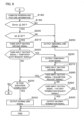
- a flowchart of FIG. 5 shows a flow from task information obtainment processing to control current output processing in the automatic operation control.
- a flowchart of FIG. 6 shows a flow from position and posture information computation processing to end signal output processing in the automatic operation control.
- step S110 the first input section 100 obtains task information from the management system 180.
- the processing then proceeds to step S120.
- the operation plan section 90 generates operation plan information on the basis of the task information obtained in step S110.
- the processing then proceeds to step S130.
- step S130 the first output section 110 outputs the operation plan information generated in step S120 to the management system 180.
- step S140 the first input section 100 obtains task information from the management system 180.
- step S140 the second input section 101 obtains a signal from the management system 180 .(which signal will hereinafter be also written as a second input section signal).
- the processing then proceeds to step S150.
- step S150 the automatic operation control section 91 determines whether or not the second input section signal obtained in step S140 is an approval signal.
- step S160 the automatic operation control section 91 determines in step S150 that the second input section signal is an approval signal.
- step S110 when the automatic operation control section 91 determines in step S150 that the second input section signal is not an approval signal (that is, determines that the second input section signal is a disapproval signal).
- step S150 When a negative determination is made in step S150, the automatic control by the controller 40 (processing from step S160 on down) is not performed. When an affirmative determination is made in step S150, the automatic control by the controller 40 (processing from step S160 on down) is performed.
- step S160 the automatic operation control section 91 computes the target velocities of the respective hydraulic actuators on the basis of the present position and posture information of the hydraulic excavator 1 (present position and posture of the hydraulic excavator 1) as a computation result of the position and posture computing section 43 and the operation plan information.
- step S165 the present position and posture information of the hydraulic excavator 1 is computed in step S180 to be described later, and is retained in the nonvolatile memory 40b.
- step S165 the actuator control section 81 computes the target pilot pressures of the respective flow control valves D1 to D6 on the basis of the target velocities computed in step S160. The processing then proceeds to step S170.
- step S170 the solenoid proportional valve control section 44 computes control current values to be supplied to the solenoids of the respective solenoid proportional valves 54a to 59b on the basis of the target pilot pressures computed in step S170. The processing then proceeds to step S175.
- step S175 the solenoid proportional valve control section 44 supplies control currents corresponding to computation results in step S170to the solenoids of the solenoid proportional valves 54a to 59b.
- step S180 see FIG. 6 ).
- step 5180 the position and posture computing section 43 computes the present position of the machine body 1B in the geographic coordinate system and the present azimuth angle of the upper swing structure 12 on the basis of a sensing result of the machine body position sensor 36.
- step S180 the position and posture computing section 43 computes the position and posture information of the hydraulic excavator 1 on the basis of the present position of the machine body 1B in the geographic coordinate system and the present azimuth angle of the upper swing structure 12, the sensing result of the posture sensor 50, and dimensional information of parts of the hydraulic excavator 1 which dimensional information is stored in the nonvolatile memory 40b.
- the processing then proceeds to step S190.
- the position and posture information of the hydraulic excavator 1 includes the position and posture of the work device 1A, the position and posture of the upper swing structure 12, and the position and posture of the lower track structure 11.
- the trajectory deviation determining section 92 performs trajectory deviation determination processing.
- the trajectory deviation determining section 92 computes the shortest distance Dmin between the position of the specific point of the work device 1A which position is included in a result of the computation in step S180 and the planned operation trajectory included in the operation plan information generated in step S120. Further, the trajectory deviation determining section 92 determines whether or not the shortest distance Dmin is equal to or less than the distance threshold value D0. The trajectory deviation determining section 92 determines that the specific point of the work device 1A does not deviate from the planned operation trajectory when the trajectory deviation determining section 92 determines in step S190 that the shortest distance Dmin is equal to or.less than the distance threshold value D0.
- step S200 The trajectory deviation determining section 92 determines that the specific point of the work device 1A deviates from the planned operation trajectory when the trajectory deviation determining section 92 determines in step S190 that the shortest distance Dmin is more than the distance threshold value D0. The processing then proceeds to step S250.
- step S200 the time deviation determining section 93 performs time deviation determination processing.
- the time deviation determining section 93 identifies a position on the planned operation trajectory which position is closest to the position of the specific point of the work device 1A, the position of the specific point being included in the result of the computation in step S180.
- the time deviation determining section 93 computes, as a difference time td, the absolute value of a difference between the present time tc and the planned time te stored in association with the identified position included in the operation plan information. Further, the time deviation determining section 93 determines whether or not the difference time td is equal to or less than the time threshold value to.
- the time deviation determining section 93 determines that the actual operation time of the hydraulic excavator 1 does not deviate from the planned operation time when the time deviation determining section 93 determines in step S200 that the difference time td is equal to or less than the time threshold value t0. The processing then proceeds to step S210. When the time deviation determining section 93 determines in step S200 that the difference time td is more than the time threshold value t0, the time deviation determining section 93 determines that the actual operation time of the hydraulic excavator 1 deviates from the planned operation time. The processing then proceeds to step S250.
- step S210 the third input section 102 obtains a signal from the management system 180 (which signal will hereinafter be also written as a third input section signal). The processing then proceeds to step S220.
- step S220 the automatic operation control section 91 determines whether or not the third input section signal obtained in step S210 is a temporary stop request signal. When the automatic operation control section 91. determines in step S220 that the third input section signal is a temporary stop request signal, the processing proceeds to step S260. When the automatic operation control section 91 determines in step S220 that the third input section signal is not a temporary stop request signal, the processing proceeds to step S230.
- step S230 the automatic operation control section 91 determines whether or not the task execution completion condition is satisfied. When it is determined in step S230 that the task execution completion condition is satisfied, the processing proceeds to step S240. When it is determined in step S230 that the task execution completion condition is not satisfied, the processing proceeds to step S160 (see FIG. 5 ).
- step S240 the second output section 111 outputs a normal end signal to the management system 180.
- the automatic operation control is then ended.
- step S250 the second output section 111 outputs an abnormal end,signal to the management system 180.
- the automatic operation control is then ended.
- step S250 the second output section 111 outputs a first abnormal end signal to the management system 180 when a negative determination is made in step S190, or the second output section 111 outputs a second abnormal end signal to the management system 180 when a negative determination is made in step S200.
- step S260 the second output section 111 outputs a temporary stop signal to the management system 180.
- the processing then proceeds to step S270.
- step S270 the third input section 102 obtains a signal (third input section signal) from the management system 180.
- the processing then proceeds to step S280.
- step S280 the automatic operation control section 91 determines whether or not the third input section signal obtained in step S270 is a resumption request signal.
- the processing proceeds to step S230.
- the processing proceeds to step S290.
- step S290 the automatic operation control section 91 determines whether or not the third input section signal obtained in step S270 is a halfway termination request signal.
- the processing proceeds to step S300.
- the processing returns to step S270.
- step S300 the second output section 111 outputs a halfway termination signal to the management system 180.
- the automatic operation control is then ended.
- a main operation of the hydraulic excavator 1 according to the present embodiment will be described.
- a main operation of the hydraulic excavator 1 will be described by taking as an example a case where the kind of the automatic control is excavation work.
- the management server 181 when the hydraulic excavator 1 is in a stop state S1, the claw tip of the bucket 10 is positioned at a starting point of the excavation work.
- the management server 181 when the manager performs an input operation for task information by the input device 185, the management server 181,generates the task information, and transmits the task information to the hydraulic excavator 1.
- the controller 40 of the hydraulic excavator 1 generates operation plan information on the basis of the input task information (S110 in FIG. 5 ⁇ S120) .
- the controller 40 transmits the generated operation plan information to the management system 180 (S130 in FIG. 5 ).
- the management server 181 displays the input operation plan information on the display device 184.
- the operation plan information output from the controller 40 to the management system 180 includes the planned operation trajectory as the trajectory of the specific point of the work device 1A, the time series information of the planned position of the work device 1A, the time series information of the planned posture of the work device 1A, and the time series information of the planned position of the machine body 1B.
- the manager can check the operation plan information, and determine whether or not to make the automatic control based on the operation plan information performed.
- the management server 181 generates a composite image in which an image of a line representing the planned operation trajectory and a terrain profile image are superimposed on each other when the planned operation trajectory is input to the management server 181, and the management server 181 outputs the composite image to the display device 184. Consequently, the composite image of the image of the line representing the planned operation trajectory and the terrain profile image is displayed on the display screen of the display device 184.
- the manager can check the operation plan information before the automatic control is performed by the hydraulic excavator 1.
- the manager performs a disapproval operation by the input device 185 when the manager determines that an operation based on the operation plan information is not desired to be performed.
- the management server 181 When the disapproval operation is performed by the input device 185, the management server 181 generates a disapproval signal, and transmits the disapproval signal to the hydraulic excavator 1.
- the manager can check the operation plan information in advance, and therefore prevent an operation not intended by the manager from being performed by the hydraulic excavator 1.
- a display mode of the operation plan information is not limited to a mode in which the composite image of the image of the line representing the planned operation trajectory and the terrain profile image is displayed on the display screen of the display device 184, but the display mode can be various display modes.
- the management server 181 may display the time series information of the planned position of the work device 1A which time series information is included in the operation plan information in a table format or a graph format on the display screen of the display device 184.
- the management server 181 may display an animation of the hydraulic excavator 1 on the display screen of the display device 184 on the basis of the time series information of the planned posture of the work device 1A which time series information is included in the operation plan information by a well-known key frame method or the like.
- the management server 181 displays, for example, a composite image of an image of a line representing a planned movement trajectory of the machine body 1B and the terrain profile image on the display screen of the display device 184 on the basis of the time series information of the planned position of the machine body 1B.
- the manager performs an input operation for new task information when the manager has performed the disapproval operation.
- the controller 40 generates new operation plan information based on the new task information, and outputs the new operation plan information to the management system 180 (S140 in FIG. 5 ⁇ No in S150 ⁇ S110 ⁇ S120 ⁇ S130), so that the new operation plan information is displayed on the display screen of the display device 184.
- the manager performs an approval operation by the input device 185 when the manager determines that there is no problem in the operation plan information.
- the management server 181 When the approval operation is performed by the input device 185, the management server 181 generates an approval signal, and transmits the approval signal to the hydraulic excavator 1.
- the controller 40 performs the automatic control of the hydraulic excavator 1 on the basis of the operation plan information when the approval signal is input to the controller 40 (S140 in FIG. 5 -+ Yes in S150 ⁇ S160 -+ ... ⁇ S180 in FIG. 6 ⁇ Yes in S190 ⁇ Yes in S200 -+ S210 ⁇ No in S220 -> No in S230).
- the controller 40 performs the automatic control of each hydraulic actuator (5, 6, and 7) such that the claw tip of the bucket 10 moves along the planned operation trajectory.
- an area indicated by hatching in FIG. 4 is an area enclosed by an upper boundary obtained by offsetting the planned operation trajectory upward by the distance threshold value D0 and a lower boundary obtained by offsetting the planned operation trajectory downward by the distance threshold value D0 (which area will hereinafter be written as an allowable area) .
- the automatic control is stopped when the claw tip as the specific point of the bucket 10 moves from within the allowable area to outside the allowable area, that is, when the distance between the specific point of the bucket 10 and the planned operation trajectory becomes more than the distance threshold value D0, due to an effect of soil to be excavated or the like during the automatic control state S2 (No in S190 in FIG. 6 ⁇ S250 ⁇ END). Therefore, according to the present embodiment, an operation not approved by the manager can be prevented from being performed.
- an abnormal end signal is output from the controller 40 to the management system 180 (S250 in FIG. 6 ) .
- an image of a message or the like indicating that the automatic control is stopped because the claw tip of the bucket 10 deviates from the planned operation trajectory is displayed on the display screen of the display device 184. Therefore, the manager can recognize the stopping of the automatic control and a reason for the stopping of the automatic control, so that the manager can utilize them for the generation of next task information.
- the automatic control is stopped when the difference between the actual operation time of the bucket 10 and the planned operation time becomes more than the time threshold value t0 due to an effect of soil to be excavated or the like during the automatic control state S2 (No in S200 in FIG. 6 ⁇ S250 ⁇ END) .
- an operation not approved by the manager can be prevented from being performed.
- an abnormal end signal is output-from the controller 40 to the management system 180 (S250 in FIG. 6 ).
- an image of a message or the like indicating that the automatic control is stopped because the actual operation time of the work device 1A deviates from the planned operation time is displayed on the display screen of the display device 184.
- the manager can recognize the stopping of the automatic control and a reason for the stopping of the automatic control, so that the manager can utilize them for the generation of next task information. For example, such a work with a delay can be prevented from being performed repeatedly, and therefore the delaying of work by the automatic control can be prevented.
- the manager When the manager desires to stop the automatic control of the hydraulic excavator. 1 temporarily for some reason during the automatic control state S2, the manager performs a temporary stop request operation by the input device 185.
- the management server 181 When the temporary stop request operation is performed by the input device 185, the management server 181 generates a temporary stop request signal, and transmits the temporary stop request signal to the hydraulic excavator 1.
- the controller 40 stops the automatic control when the temporary stop request signal is input to the controller 40 (S210 in FIG. 6 -. Yes in S220 -+ S260 ⁇ S270 ⁇ No in S280 ⁇ No in S290) .
- the controller 40 when the controller 40 temporarily stops the automatic control, the controller 40 outputs a temporary stop signal to the management system 180 (S260 in FIG. 6 ). As a result, an image such as a message indicating that the automatic control is temporarily stopped is displayed on the display screen of the display device 184. Thus, the manager can confirm that the automatic control is temporarily stopped.
- the manager When the manager desires to resume the automatic control during a temporary stop state, the manager performs a resumption request operation by the input device 185.
- the management server 181 When the resumption request operation is performed by the input device 185, the management server 181 generates a resumption request signal, and transmits the resumption request signal to the hydraulic excavator 1.
- the controller 40 resumes the automatic control when the resumption request signal is input to the controller 40 (S270 in FIG. 6 ⁇ Yes in S280 ⁇ No in S230 , S160 in FIG. 5 -+ ).
- the manager When the manager desires to terminate the automatic control halfway during the temporary stop state, the manager performs a halfway termination request operation by the input device 185.
- the management server 181 When the halfway termination request operation is performed by the input device 185, the management server 181 generates a halfway termination request signal, and transmits the halfway termination request signal to the hydraulic excavator 1.
- the controller 40 terminates the automatic control halfway when the halfway termination request signal is input to the controller 40 (S270 in FIG. 6 ⁇ No in S280 ⁇ Yes in S290 ⁇ S300 ⁇ END) .
- the controller 40 when the controller 40 terminates the automatic control halfway, the controller 40 outputs a halfway termination signal to the management system 180 (S300 in FIG. 6 ). As a result, an image such as a message indicating that the automatic control is terminated halfway is displayed on the display screen of the display device 184. Therefore, the manager can confirm that the automatic control is terminated halfway.
- a normal end signal is output from the controller 40 to the management system 180, and the hydraulic excavator 1 is set in a stop state S3 (Yes in S230 in FIG. 6 ⁇ S240 ⁇ END) .
- the controller 40 when the controller 40 presents the operation plan information of the hydraulic excavator 1 to the management system 180 and obtains the approval signal from the management system 180, the controller 40 performs the automatic control according to the operation plan information. On the other hand, the controller 40 does not perform the automatic control according to the operation plan information when the controller 40 does not obtain the approval signal from the management system 180. Therefore, according to the present embodiment, automatic control not intended by the manager can be prevented from being performed. That is, according to the present embodiment, it is possible to provide the hydraulic excavator 1 that can appropriately perform an operation intended by the manager.
- the operation plan information includes the planned operation trajectory as the trajectory of the specific point of the work device 1A.
- the controller 40 determines whether or not the specific point of the work device 1A deviates from the planned operation trajectory during the execution of the automatic control.
- the controller 40 stops the automatic control, and outputs an abnormal end signal to the management system 180 when the controller 40 determines that the specific point of the work device 1A deviates from the planned operation trajectory during the execution of the automatic control.
- the automatic control is stopped when the specific point of the work device 1A deviates from the planned operation trajectory, so that an operation of the hydraulic excavator 1 which operation is not intended by the manager can be prevented from being performed.
- the controller 40 can present information indicating that the automatic control is ended abnormally to the management system 180. Therefore, the manager can recognize that the automatic control is ended abnormally.
- the controller 40 determines whether or not the actual operation time of the work device 1A deviates from the planned operation time during the execution of the automatic control. When the controller 40 determines that the actual operation time of the work device 1A deviates from the planned operation time during the execution of the automatic control, the controller 40 ends the automatic control, and outputs an abnormal end signal to the management system 180.
- the automatic control is stopped when the actual operation time of the work device 1A deviates from the planned operation time, so that an operation of the hydraulic excavator 1 which operation is not intended by the manager can be prevented from being performed. For example, it is possible to prevent taking a longer operation time than an operation time intended by the manager.
- the controller 40 can present information indicating that the automatic control is ended abnormally to the management system 180. Therefore, the manager can recognize that the automatic control is ended abnormally.
- the controller 40 outputs a normal end signal to the management system 180 when the controller 40 ends the automatic control without determining that the specific point of the work device 1A deviates from the planned operation trajectory and without determining that the actual operation time of the work device 1A deviates from the planned operation time.
- the controller 40 can present information indicating that the automatic control is ended normally to the management system 180. Therefore, the manager can recognize a state in which an input operation for next task information can be performed.
- the controller 40 temporarily stops the automatic control and outputs a temporary stop signal to the management system 180 when a temporary stop request signal is input from the management system 180 to the controller 40 during the execution of the automatic control.
- the manager can temporarily stop the automatic control by outputting the temporary stop request signal from the management system 180 when the manager desires to stop the automatic control temporarily for some reason.
- the controller.40 can present information indicating that the automatic control is temporarily stopped to the management system 180. Therefore, the manager can recognize a state in which the automatic control is temporarily stopped.
- the controller 40 resumes the automatic control when a resumption request signal is input from the management system 180 to the controller 40 during the temporary stop of the automatic control.
- the controller 40 ends the automatic control and outputs a halfway termination signal to" the management system 180 when a halfway termination request signal is input from the management system 180 to the controller 40 during the temporary stop of the automatic control.
- the manager can resume the automatic control by outputting the resumption request signal from the management system 180 after temporarily stopping the automatic control.
- the manager can terminate the automatic control halfway by outputting the halfway termination request signal from the management system 180 when the manager desires to terminate the automatic control halfway.
- the controller 40 can present information indicating that the automatic control is terminated halfway to the management system 180. Therefore, the manager can recognize that the automatic control is terminated halfway.
- the controller 40 computes the position of the machine body 1B on the basis of a sensing result of the machine body position sensor 36, and on the basis of a result of the computation and a sensing result of the posture sensor 50, computes the position and posture of the work device 1A.
- the position and posture of the work device 1A in the geographic coordinate system for example, can be computed, and therefore the automatic control based on the operation plan information in the geographic coordinate system can be performed.
- the controller 40 can perform the automatic control on the basis of at least one of the position and posture of the work device 1A and the operation plan information.
- the operation plan information output from the controller 40 to the management system 180 includes the planned operation trajectory as the trajectory of the specific point of the work device 1A, the time series information of the planned position of the work device 1A, the time series information of the planned posture of the work device 1A, and the time series information of the planned position of the machine body 1B.
- the management system 180 can display, on the display device 184, the planned operation trajectory, the time series information of the planned position of the work device 1A, the time series information of the planned posture of the work device 1A, and the time series information of the planned position of the machine body 1B.
- FIG. 7 is a diagram similar to FIG. 3 , and is a functional block diagram of a controller 240 according to the second embodiment.
- FIG. 8 is a diagram similar to FIG. 4 , and is a diagram showing the planned operation trajectory when excavation work is performed as well as the work device 1A in which the claw tip of the bucket 10 operates so as to follow the planned operation trajectory.
- FIG. 8 shows a reference planned operation trajectory and a corrected planned operation trajectory as the planned operation trajectory.
- an operation plan section 290 generates reference operation plan information and corrected operation plan information on the basis of the task information.
- the reference operation plan information corresponds to the operation plan information described in the first embodiment.
- the corrected operation plan information is information obtained by correcting the reference operation plan information, and is information different from the reference operation plan information.
- the reference operation plan information includes a planned operation trajectory as the trajectory of the specific point of the work device 1A (which trajectory will hereinafter be written also as the reference planned operation trajectory), the time series information of the planned position of the work device 1A, the time series information of the planned posture of the work device 1A, and the time series information of the planned position of the machine body 1B.
- the corrected operation plan information includes a planned operation trajectory as the trajectory of the specific point of the work device 1A (which trajectory will hereinafter be written also as the corrected planned operation trajectory), the time series information of the planned position of the work device 1A, the time series information of the planned posture of the work device 1A, and the time series information of the planned position of the machine body 1B.
- the corrected planned operation trajectory is a trajectory different from the reference planned operation trajectory, and is also used to indicate a range in which there is a possibility of correcting the planned operation trajectory during the execution of the automatic control, as will be described later.
- An automatic operation control section 291 determines whether or not a correction condition is satisfied during the execution of the automatic control.
- the automatic operation control section 291 performs reference automatic control of the hydraulic actuator on the basis of the reference operation plan information and the sensing result of the posture sensor 50 when the correction condition is not satisfied.
- the automatic operation control section 291 performs corrected automatic control of the hydraulic actuator on the basis of the corrected operation plan information and the sensing result of the posture sensor 50 when the correction condition is satisfied.
- the correction condition is, for example, set in advance so as to be satisfied when the soil to be excavated is harder than expected.
- the correction condition can be, for example, set as a condition that is satisfied when a state in which any one of the pressures of the hydraulic cylinders (5, 6, and 7) is equal to or higher than a pressure.threshold value continues for a predetermined period of time or more.
- the controller 240 includes a fourth input section 203.
- a sensing result of a pressure sensor 60 is input to the fourth input section 203.
- the pressure sensor 60 includes a plurality of pressure sensors that sense the pressures of bottom side oil chambers of the hydraulic cylinders (5, 6, and 7) and the pressures of rod side oil chambers of the hydraulic cylinders (5, 6, and 7).
- the automatic operation control section 291 determines that the correction condition is satisfied when a state in which any one of the pressures of the bottom side oil chambers of the hydraulic cylinders (5, 6, and 7) and the pressures of the rod side oil chambers' of the hydraulic cylinders (5, 6, and 7) is equal to or higher than the pressure threshold value continues for the predetermined period of time or more.
- the automatic operation control section 291 determines that the correction condition is not satisfied when the state in which any one of the pressures of the bottom side oil chambers of the hydraulic cylinders (5, 6, and 7) and the pressures of the rod side oil chambers of the hydraulic cylinders (5, 6, and 7) is equal to or higher than the pressure threshold value does not continue for the predetermined period of time or more.
- a trajectory deviation determining section 292 determines whether or not the specific point of the work device 1A deviates from the reference planned operation trajectory at least during the execution of the reference. automatic control. In addition, the trajectory deviation determining section 292 determines whether or not the specific point of the work device 1A deviates from the corrected planned operation trajectory at least during the execution of the corrected automatic control.
- a time deviation determining section 293 determines whether or not the actual operation time of the work device 1A deviates from the planned operation time at least during the execution of the reference automatic control and during the execution of the corrected automatic control.
- the automatic operation control section 291 ends the reference automatic control, and generates a first abnormal end signal. Further, the second output section 111 outputs the first abnormal end signal to the management system 180.
- the automatic operation control section 291 ends the corrected automatic control, and generates, a first abnormal end signal. Further, the second output section 111 outputs the first abnormal end signal to the management system 180.
- the automatic operation control section 291 ends the reference automatic control, and generates a second abnormal end signal. Further, the second output section 111 outputs the second abnormal end signal to the management system 180.
- the automatic operation control section 291 ends the corrected automatic control, and generates a second abnormal end signal. Further, the second output section 111 outputs the second abnormal end signal to the management system 180.
- the automatic operation control section 291 generates a normal end signal when the automatic operation control section 291 ends the reference automatic control without the trajectory deviation determining section 292 determining that the specific point of the work device 1A deviates from the reference planned operation trajectory.and without the time deviation determining section 293 determining that the actual operation time of the work device 1A deviates from the planned operation time.
- the second output section 111 outputs the normal end signal to the management system 180.
- the automatic operation control section 291 generates a normal end signal when the automatic operation control section 291 ends the corrected automatic control without the trajectory deviation determining section 292 determining that the specific point of the work device 1A deviates from the corrected planned operation trajectory and without the time deviation determining section 293 determining that the actual operation time of the work device 1A deviates from the planned operation time. Further, the second output section 111 outputs the normal end signal to the management system 180.
- a main operation of the hydraulic excavator 1 according to the present embodiment will be described.
- a main operation of the hydraulic excavator 1 will be described by taking as an example a case where the kind of the automatic control is excavation work.
- a stop state S4 the claw tip of the bucket 10 is positioned at a starting point of the excavation work.
- the management server 181 when the manager performs an input operation for task information by the input device 185, the management server 181 generates the task information, and transmits the task information to, the hydraulic excavator 1.
- the controller 240 of the hydraulic excavator 1 generates operation plan information on the basis of the input task information.
- the controller 240 transmits the generated operation plan information to the management system 180.
- the management server 181 displays the input operation plan information on the display device 184.
- the operation plan information includes the reference operation plan information generated on the basis of the task information and the corrected operation plan information obtained by correcting the reference operation plan information.
- the management server 181 displays, on the display screen of the display device 184, a range in which there is a possibility of correcting the planned operation trajectory during the execution of the automatic control.
- the range in which there is a possibility of correcting the planned operation trajectory during the execution of the automatic control is, for example, a range enclosed by the reference planned operation trajectory and the corrected planned operation trajectory.
- the manager can check the operation plan information including the corrected operation plan information, and determine whether or not to make the automatic control based on the operation plan information performed.
- the manager performs a disapproval operation by the input device 185 when the manager determines that an operation based on the operation plan information is not desired to be performed.
- the manager performs an approval operation by the input device 185 when the manager determines that there is no problem in the operation plan information.
- the management server 181 When the approval operation is performed by the input device 185, the management server 181 generates an approval signal, and transmits the approval signal to the hydraulic excavator 1.
- the controller 240 performs the reference automatic control of the hydraulic excavator 1 on the basis of the reference operation plan information when the approval signal is input to the controller 240.
- the controller 240 performs the reference automatic control of each hydraulic actuator (5, 6, and 7) such that the claw tip of the bucket 10 moves along the reference planned operation trajectory.
- a state S5 in which the reference automatic control is performed (which state will hereinafter be written also as a reference automatic control state)
- the controller 240 monitors whether or not the actual operation of the hydraulic excavator 1 deviates with respect to the reference operation plan information.
- the reference automatic control is stopped when the actual operation of the hydraulic excavator 1 deviates with respect to the reference operation plan information during the reference automatic control state S5.
- the controller 240 When the correction condition is satisfied during the reference automatic control state S5, the controller 240 performs the corrected automatic control of each hydraulic actuator (5, 6, and 7) such that the claw tip of the bucket 10 moves along the corrected planned operation trajectory.
- a state transition is made from the reference automatic control state S5 to a state S6 in which the corrected automatic control is performed (which state will hereinafter be written also as a corrected automatic control state)
- an allowable area corresponding to the corrected planned operation trajectory is set.
- the controller 240 monitors whether or not the actual operation of the hydraulic excavator 1 deviates with respect to the corrected operation plan information.
- the corrected automatic control is stopped when the actual operation of the hydraulic excavator 1. deviates with respect to the corrected operation plan information during the corrected automatic control state S6.
- a normal end signal is output from the controller 240 to the management system 180, and the hydraulic excavator 1 is set in a stop state S7.
- Such a second embodiment can provide advantages similar to the advantages described in the first embodiment.
- the controller 240 presents the operation plan information including a range in which there is a possibility of correcting the planned operation trajectory, and performs the automatic control according to the operation plan information when an approval signal is obtained from the management system 180.
- the controller 240 does not perform the automatic control according to the operation plan information when the controller 240 does not obtain the approval signal from the management system 180. Therefore, according to the present embodiment, automatic control not intended by the manager can be prevented from being performed. That is, according to the present second embodiment, as in the first embodiment, it is possible to provide the hydraulic excavator 1 that can appropriately perform an operation intended by the manager.
- the present second embodiment corrects the operation trajectory appropriately according to conditions, and can therefore improve work efficiency. For example, when the soil to be excavated is harder than expected by the manager, the automatic control of excavation work according to the corrected planned operation trajectory assuming hard soil is performed. Therefore, as compared with a case where the automatic control of excavation work according to the reference planned operation trajectory is performed when the soil to be excavated is hard, accuracy of the excavation work can be improved, and work efficiency can be improved by preventing the work from being performed again.
- the controller 240 stops the reference automatic control and outputs an abnormal end signal to the management system 180 when the controller 240 determines that the specific point of the work device 1A deviates from the reference planned operation trajectory or that the actual operation time of the work device 1A deviates from the planned operation time during the execution of the reference automatic control.
- the controller 240 stops the corrected automatic control and outputs an abnormal end signal to the management system 180 when the controller 240 determines that the specific point of the work device 1A deviates from the corrected planned operation trajectory or that the actual operation time of the work device 1A deviates from the planned operation time during the execution of the corrected automatic control.
- the controller 240 outputs a normal end signal to the management system 180 when the controller 240 ends the reference automatic control without determining that the specific point of the work device 1A deviates from the reference planned operation trajectory and without determining that the actual operation time of the work device 1A deviates from the planned operation time.
- the controller 240 outputs a normal end signal to the management system 180 when the controller 240 ends the corrected automatic control without determining that the specific point of the work device 1A deviates from the corrected planned operation trajectory and without determining that the actual operation time of the work device 1A deviates from the planned operation time.
- the present second embodiment can provide advantages similar to those of (2) to (4) described in the first embodiment even when not only the reference automatic control but also the corrected automatic control is performed.
- the specific point of the work device 1A is a central point in the left-right width direction at , the claw tip of the bucket 10.
- the present invention is not limited to this.
- a left end point and a right end point of the claw tip of the bucket 10 may each be the specific point of the work device 1A.
- the position of the specific point of the bucket 10 may be changed according to the kind of the automatic control.
- a point on the back surface of the bucket 10 is preferably set as the specific point of the work device 1A.
- the hydraulic excavator 1 includes the machine body position sensor 36.
- the hydraulic excavator 1 may not include the machine body position sensor 36. In this case, it suffices to define the operation plan information and the positional information of each part of the hydraulic excavator 1 in an excavator reference coordinate system.
- the operation plan information output from the controller 40 or 240 to the management system 180 includes the planned operation trajectory as the trajectory of the specific point of the work device 1A, the time series information of the planned position of the work device 1A, the time series information of the planned posture of the work device 1A, and the time series information of the planned position of the machine body 1B.
- the operation plan information may be included in the operation plan information.
- the operation plan information when the kind of the automatic control is work that does not involve vehicle movement, it suffices for the operation plan information to include at least any one of the planned operation trajectory as the trajectory of the specific point of the work device 1A, the time series information of the planned position of the work device 1A, and the time series information of the planned posture of the work device 1A.
- the operation plan information when the kind of the automatic control is vehicle movement, it suffices for the operation plan information to include the time series information of the planned position of the machine body 1B.
- the posture sensor 50 includes the angle sensors (30, 31, and 32) as the posture sensors that sense the posture information of the boom 8, the arm 9, and the bucket 10.
- the posture sensor 50 may include stroke sensors that sense stroke amounts of the hydraulic cylinders (5, 6, and 7) as the posture information in place of the angle sensors (30, 31, and 32).
- the position and posture computing section 43 computes the boom angle, the arm angle, and the bucket angle on the basis of the stroke amounts of the hydraulic cylinders (5, 6, and 7).
- controllers 40 and 240 determine whether or not there is a positional and a temporal deviation of the actual operation of the hydraulic excavator 1 with respect to the operation plan information, and stop the automatic control when there is a deviation.
- the controllers 40 and 240 may, for example, determine whether or not there is a positional or a temporal deviation of the actual operation of the hydraulic excavator 1 with respect to the operation plan information, and stop the automatic control when there is a deviation.
- the processing of determining a deviation of the actual operation of the hydraulic excavator 1 with respect to the operation plan information and the processing of stopping the automatic control on the basis of a result of the determination can be omitted.
- the work machine is the hydraulic excavator 1 having the bucket 10.
- the present invention may be applied to work machines having attachments other than the bucket.
- the work machine is not limited to a case where the work machine is a crawler type hydraulic excavator.
- the present invention can be applied to various work machines such as a wheeled hydraulic excavator, and a wheel loader.
- the work.machine is not limited to movable work machines.
- the present invention can be applied also to a work machine having a swing structure provided to a machine body of a fixed type, and having an articulated work device provided to the swing structure.
Landscapes
- Engineering & Computer Science (AREA)
- Mining & Mineral Resources (AREA)
- Civil Engineering (AREA)
- General Engineering & Computer Science (AREA)
- Structural Engineering (AREA)
- Mechanical Engineering (AREA)
- Physics & Mathematics (AREA)
- General Physics & Mathematics (AREA)
- Life Sciences & Earth Sciences (AREA)
- General Life Sciences & Earth Sciences (AREA)
- Paleontology (AREA)
- Operation Control Of Excavators (AREA)
- Component Parts Of Construction Machinery (AREA)
Abstract
Description
- The present invention relates to a work machine.
- There is work in which soil is excavated by a work machine such as a hydraulic excavator and the excavated soil is loaded onto a transportation vehicle such as a dump truck or the like. A technology for performing such excavation and loading work by automatic control is known.
-
Patent Document 1 discloses a control system that automatically plans and performs a task related to excavation and loading work on the basis of terrain profile data measured by using a sensor system mounted in a hydraulic excavator. This control system measures necessary parts of an excavation area, a movement path, and a load area by using two scanning sensors before and after completion of excavation work and before and after completion of loading work, and plans and performs the task automatically on the basis of the measured data. -
Patent Document 2 discloses a work machine including a controller that determines a swing path connecting a present position of a work implement to an excavation start position on the basis of measured terrain profile data, and moves the work implement to the excavation start position according to the swing path. -
- Patent Document 1:
JP-2000-136549-A - Patent Document 2:
JP-2020-020153-A - In the technologies described in
Patent Document 1 andPatent Document 2, the controller automatically performs processing from the planning of an operation of the work machine to control of the operation of the work machine on the basis' of the plan. Therefore, an operation not intended by a manager may be performed by the work machine. - It is an object of the present invention to provide a work machine that can appropriately perform an operation intended by a manager.
- A work machine according to one aspect of the present invention includes: a work device; a posture sensor that senses posture information of the work device; a hydraulic actuator that drives the work device; and a controller configured to generate operation plan information on a basis of task information necessary for automatic control, the task information being obtained from an external system, and perform automatic control of the hydraulic actuator on a basis of the operation plan information and a sensing result of the posture sensor. The controller is configured to output the operation plan information to the external system, not perform the automatic control when an approval signal indicating that the operation plan information is approved is not input from the external system, and perform the automatic control when the approval signal is input from the external system.
- According to the present invention, it is possible to provide a work machine that can appropriately perform an operation intended by a manager.
-
-
FIG. 1 is a configuration diagram of a hydraulic excavator according to a first embodiment of the present invention. -
FIG. 2 is a diagram showing a hydraulic drive system of the hydraulic excavator according to the first embodiment of the present invention. -
FIG. 3 is a functional block diagram of a controller according to the first embodiment of the present invention. -
FIG. 4 is a diagram showing a planned operation trajectory when excavation work is performed as well as a work device in which a claw tip of a bucket operates so as to follow the planned operation trajectory. -
FIG. 5 is a flowchart of automatic operation control performed by the controller, and shows a flow from task information obtainment processing to control current output processing. -
FIG. 6 is a flowchart of the automatic operation control performed by the controller, and shows a flow from position and posture information computation processing to end signal output processing. -
FIG. 7 is a functional block diagram of a controller according to a second embodiment of the present invention. -
FIG. 8 is a diagram showing a planned operation trajectory when excavation work is performed as well as the work device in which the claw tip of the bucket operates so as to follow the planned operation trajectory, and shows a reference planned operation trajectory and a corrected planned operation trajectory as the planned operation trajectory. - A work machine according to an embodiment of the present invention will hereinafter be described with reference to the drawings. Incidentally, in the following, description will be made of an example in which the work machine is a hydraulic excavator having a
bucket 10 as a work tool (attachment) at a distal end of a work device. - In addition, in the present document, in cases where there are a plurality of identical constituent elements, alphabetic characters may be attached to ends of reference numerals (numbers) thereof. However, the plurality of constituent elements may be denoted collectively with the alphabetic characters omitted. For example, when there are two solenoid
proportional valves -
FIG. 1 is a configuration diagram of ahydraulic excavator 1 according to a first embodiment of the present invention. As shown inFIG. 1 , thehydraulic excavator 1 includes amachine body 1B and an articulated front work device (hereinafter written simply as a work device) 1A attached to the machine body .lB. Themachine body 1B includes alower track structure 11 made to travel by a left and a right travellinghydraulic motor upper swing structure 12 attached onto thelower track structure 11 and swung by a swinghydraulic motor 4. - The
work device 1A includes a plurality of driven members (aboom 8, anarm 9, and a bucket 10) and a plurality of hydraulic actuators that drive the driven members. The plurality of driven members are coupled in series with each other. A proximal end portion of theboom 8 is pivotably supported on a front portion of theupper swing structure 12 via a boom pin. Thearm 9 is pivotably coupled with a distal end portion of theboom 8 via an arm pin. Thebucket 10 as a work tool is pivotably coupled with a distal end portion of thearm 9 via a bucket pin. Theboom 8 is driven by a hydraulic cylinder (hereinafter also written as a boom cylinder) 5 as a hydraulic actuator. Thearm 9 is driven by a hydraulic cylinder (hereinafter also written as an arm cylinder) 6 as a hydraulic actuator. Thebucket 10 is driven by a hydraulic cylinder (hereinafter also written as a bucket cylinder) 7 as a hydraulic actuator. - In order to be able to measure the pivot rotational angles of the
boom 8, thearm 9, and thebucket 10, aboom angle sensor 30 is attached to theboom 8, anarm angle sensor 31 is attached to thearm 9, and abucket angle sensor 32 is attached to abucket link 13. A machine bodyinclination angle sensor 33 that senses the inclination angle of the upper swing structure 12 (machine body 1B) with respect to a reference plane (for example, a horizontal plane) is attached to theupper swing structure 12. - The
upper swing structure 12 is mounted with hydraulic devices such as anengine 18 as a prime mover and hydraulic pumps driven by theengine 18.FIG. 2 is a diagram showing a hydraulic drive system of thehydraulic excavator 1. As shown inFIG. 2 , the hydraulic drive system includes theengine 18, amain pump 2, apilot pump 48, a plurality of flow control valves D1 to D6, and a plurality of solenoidproportional valves 54a to 59b. Theengine 18 drives themain pump 2 and thepilot pump 48. Thepilot pump 48 is a fixed displacement hydraulic pump. - The
main pump 2 is a variable displacement hydraulic pump whose displacement is controlled by aregulator 2a. Themain pump 2 delivers hydraulic fluid that drives the plurality of hydraulic actuators (theboom cylinder 5, the arm cylinder 6, thebucket cylinder 7, and the like). Theregulator 2a is driven by a control command from acontroller 40 mounted in theupper swing structure 12, and controls the delivery flow rate of themain pump 2. - The hydraulic fluid delivered from the
main pump 2 is supplied to theboom cylinder 5 through the flow control valve D1, is supplied to the arm cylinder 6 through the flow control valve D2, is supplied to thebucket cylinder 7 through the flow control valve D3, is supplied to the swinghydraulic motor 4 through the flow control valve D4, is supplied to the travellinghydraulic motor 3a through the flow control valve D5, and is supplied to the travellinghydraulic motor 3b through the flow control valve D6. When theboom cylinder 5, the arm cylinder 6, and thebucket cylinder 7 are elongated or contracted by the supplied hydraulic fluid, each of theboom 8, thearm 9, and thebucket 10 pivotably rotate, and consequently the posture of thework device 1A and the position of thebucket 10 are changed. When the swinghydraulic motor 4 is rotated by the supplied hydraulic fluid, theupper swing structure 12 swings with respect to thelower track structure 11. When the travellinghydraulic motors lower track structure 11 travels. - A
lock valve 39 is provided to apilot pump line 170 as a delivery pipe of thepilot pump 48. A downstream side of thelock valve 39 in thepilot pump line 170 is branched into a plurality of pilot lines C1 to C12, which are connected to the solenoidproportional valves 54a to 59b. Thelock valve 39 in the present embodiment is a solenoid selector valve. A solenoid of the solenoid selector valve is electrically connected to a position sensor of a gate lock lever 24 (seeFIG. 1 ) disposed in a cab 16 (seeFIG. 1 ). of theupper swing structure 12. The position of thegate lock lever 24 is sensed by the position sensor, and a signal corresponding to the position of thegate lock lever 24 is input from the position sensor to thelock valve 39. When the position of thegate lock lever 24 is at a lock position, thelock valve 39 is closed, and thus the supply of hydraulic operating fluid from thepilot pump 48 to the solenoidproportional valves 54a to 59b is interrupted. When the position of thegate lock lever 24 is at a lock release position, thelock valve 39 is opened, and thus the hydraulic operating fluid is supplied from thepilot pump 48 to the solenoidproportional valves 54a to 59b. That is, operation of each of the hydraulic actuators (3 to 7) is disabled in a state in which thepilot pump line 170 is interrupted by thelock valve 39. - The flow control valves D1 to D6 control flows of the hydraulic fluid supplied from the
main pump 2 to theboom cylinder 5, the arm cylinder 6, thebucket cylinder 7, the swinghydraulic motor 4, and the travellinghydraulic motors - The flow control valve D1 is driven by pilot pressures input to pressure receiving chambers E1 and E2 via the pilot lines C1 and C2 provided with the solenoid
proportional valves boom cylinder 5 while controlling a supply direction and a flow rate of the hydraulic fluid from themain pump 2. The flow control valve D2 is driven by pilot pressures input to pressure receiving chambers E3 and E4 via the pilot lines C3 and C4provided with the solenoidproportional valves main pump 2. The flow control valve D3 is driven by pilot pressures input to pressure receiving chambers E5 and E6 via the pilot lines C5 and C6 provided with the solenoidproportional valves bucket cylinder 7 while controlling a supply direction and a flow rate of the hydraulic fluid from themain pump 2. The flow control valve D4 is driven by pilot pressures input to pressure receiving chambers E7 and E8 via the pilot lines C7 and C8 provided with the solenoidproportional valves hydraulic motor 4 while controlling a supply direction and a flow rate of the hydraulic fluid from themain pump 2. The flow control valve D5 is driven by pilot pressures input to pressure receiving chambers E9 and E10 via the pilot lines C9 and C10 provided with the solenoidproportional valves hydraulic motor 3a while controlling a supply direction and a flow rate of the hydraulic fluid from themain pump 2. The flow control valve D6 is driven by pilot pressures input to pressure receiving chambers E11 and E12 via the pilot lines C11 and C12 provided with the solenoidproportional valves hydraulic motor 3b while controlling a supply direction and a flow rate of the hydraulic fluid from themain pump 2. - The solenoid
proportional valves 54a to 59b are controlled by control commands from thecontroller 40. The solenoidproportional valves 54a to 59b are pressure reducing valves that generate pilot pressures by reducing a primary pressure supplied from thepilot pump 48 to secondary pressures corresponding to the control commands (control currents) from thecontroller 40. The solenoidproportional valves 54a to 59b output the generated pilot pressures to the pressure receiving chambers (E1 to E12) of the flow control valves D1 to D6. - The
controller 40 is connected with aposture sensor 50, a machinebody position sensor 36, and a communicatingdevice 51. Theposture sensor 50 includes the boom angle sensor 30 (seeFIG. 1 ) attached to theboom 8, the arm angle sensor 31 (seeFIG. 1 ) attached to thearm 9, the bucket angle sensor 32 (seeFIG. 1 ) attached to thebucket 10, and the machine body inclination angle sensor 33 (seeFIG. 1 ) attached to themachine body 1B. These angle sensors (30, 31, 32, and 33) obtain information indicating the angles as posture information of thework device 1A, and output signals corresponding to the information. That is, the angle sensors (30, 31, 32, and 33) function as posture sensors that sense the posture information of thework device 1A. Theposture sensor 50, for example, includes, as the angle sensors (30, 31, 32, and 33), IMUs (Inertial Measurement Units) that obtain angular velocities and accelerations on three orthogonal axes and angle computing devices that compute the boom angle, the arm angle, the bucket angle, and the machine body inclination angle on the basis of information obtained by the IMUs. Incidentally, potentiometers can also be employed as the angle sensors (30, 31, and 32). - The machine
body position sensor 36 is attached to theupper swing structure 12 to sense positional information and azimuth information of the upper swing structure 12 (machine body 1B). For example, the machinebody position sensor 36 includes a plurality of GNSS (Global Navigation Satellite System) antennas (hereinafter written as GNSS antennas) 36a (seeFIG. 1 〉 and a positioning computing device that computes the position coordinates (positional information) of theupper swing structure 12 in a geographic coordinate system (global coordinate system) and the azimuth angle (azimuth information) of theupper swing structure 12 which azimuth angle is an angle from a reference azimuth on the basis of satellite signals (GNSS radio waves) from a plurality of positioning satellites which satellite signals are received by theGNSS antennas 36a. - The communicating
device 51 is a device for communicating with amanagement system 180. Thecontroller 40 transmits information to themanagement system 180 via the communicatingdevice 51, and receives information from themanagement system 180 via the communicatingdevice 51. The communicatingdevice 51 is a wireless communication device capable of performing wireless communication with acommunication line 20 as a wide area network. The communicatingdevice 51 has a communication interface including a communication antenna having a predetermined frequency band as a sensing band. Thecommunication line 20 is a mobile telephone communication network (mobile communication network) operated by a mobile telephone operator or the like, the Internet, or the like. Incidentally, the communicatingdevice 51 may send and receive information to and from themanagement system 180 directly or indirectly by using a communication system such as Wi-Fi (registered trademark), ZigBee (registered trademark), or Bluetooth (registered trademark). - The
management system 180 is an external system that remotely manages (grasps and monitors) the state of thehydraulic excavator 1. Themanagement system 180 is provided in a facility remote from thehydraulic excavator 1. Themanagement system 180 includes amanagement server 181, adisplay device 184, and aninput device 185. Themanagement server 181 includes a communicatingdevice 183 for communicating with thehydraulic excavator 1 via thecommunication line 20 and astorage device 182 such as a hard disk drive that stores information received from thehydraulic excavator 1, and the like. Themanagement server 181 transmits information to thecontroller 40 via the communicatingdevice 183, and receives information from thecontroller 40 via the communicatingdevice 183. Themanagement server 181 displays the information stored in thestorage device 182 on thedisplay device 184 such as a liquid crystal display device. A manager can grasp the state of thehydraulic excavator 1 by operating themanagement server 181 by theinput device 185 such as a keyboard and a mouse, and displaying information of the predeterminedhydraulic excavator 1 on the display device. 184. - The manager operates the
input device 185 to perform an input operation for task information necessary for automatic control to be performed by thecontroller 40 of thehydraulic excavator 1. The task information includes a kind of automatic control and a parameter for making the automatic control performed. Kinds of automatic control include, for example, excavation work, loading work, vehicle movement, excavation and loading work, movement, excavation, and loading work, and the like. An example of the parameter for making the automatic control performed will be described. As the parameter for making the automatic control of the excavation work performed, there are position coordinates in the geographic coordinate system of eight vertices for defining an excavation range in a rectangular parallelepipedic shape. As the parameter for making the automatic control of the loading work performed, there are position coordinates in the geographic coordinate system of a soil discharge point. - When the input operation for the task information by the
input device 185 is performed, themanagement server 181 generates the task information, and transmits the task information to thehydraulic excavator 1 via the communicatingdevice 183. For example, the manager selects the excavation and loading work as a kind of automatic control and performs an operation of inputting the position coordinates of the eight vertices of an area to be excavated and the position coordinates of the soil discharge point when the manager desires thehydraulic excavator 1 to perform the excavation and loading work. Thus, themanagement server 181 generates and outputs the task information in which the automatic control for a set of work from an excavation operation to a loading operation (soil discharge operation) by thehydraulic excavator 1 is set as one task. - The
controller 40 of thehydraulic excavator 1 generates operation plan information on the basis of the task information and transmits the operation plan information to themanagement system 180 via the communicatingdevice 51 when thecontroller 40 receives the task information from themanagement system 180. Incidentally, details of contents of processing of generating the operation plan information by thecontroller 40 of thehydraulic excavator 1 will be described later. - The operation plan information generated by the
controller 40 is input to themanagement system 180. Themanagement server 181 displays the input operation plan information on thedisplay device 184. When the manager visually checks the operation plan information displayed on a display screen of thedisplay device 184, and approves the execution of the automatic control based on the operation plan information, the manager performs an approval operation by theinput device 185. When the approval operation by theinput device 185 is performed, themanagement server 181 generates an approval signal indicating that the operation plan information is approved, and transmits the approval signal to thehydraulic excavator 1 via the communicatingdevice 183. When the manager visually checks the operation plan information displayed on the display screen of thedisplay device 184, and does not approve the execution of the automatic control based on the operation plan information, the manager performs a disapproval operation by theinput device 185. When the disapproval operation by theinput device 185 is performed, themanagement server 181 generates a disapproval signal indicating that the operation plan information is not approved, and transmits the disapproval signal to thehydraulic excavator 1 via the communicatingdevice 183. That is, themanagement system 180 outputs the approval signal or the disapproval signal according to the operation of theinput device 185. - The
controller 40 performs the automatic control of the hydraulic actuator on the basis of the operation plan information and a sensing result of theposture sensor 50 when the approval signal from themanagement system 180 is input to thecontroller 40 of thehydraulic excavator 1. Incidentally, thecontroller 40 does not perform the automatic control when the approval signal is not input from themanagement system 180. When the automatic control is ended normally, thecontroller 40 generates a normal end signal, and transmits the normal end signal to themanagement system 180 via the communicatingdevice 51. - The
management server 181 displays an image of a message or the like indicating that the automatic control is ended normally on the display screen of thedisplay device 184 when themanagement server 181 receives the normal end signal. The manager performs an input operation for task information again when the manager confirms that the automatic control is ended normally. Thus, in the present embodiment, work using thehydraulic excavator 1 is progressed by repeating (1) an input operation for task information by the manager, (2) the generation of operation plan information by thecontroller 40 of thehydraulic excavator 1, (3) an approval operation for the operation plan information by the manager, and (4) the automatic control based on the operation plan information by thecontroller 40 of thehydraulic excavator 1. - The
management server 181 displays a message indicating that the automatic control is being performed on the display screen of thedisplay device 184 when themanagement server 181 receives information indicating that the automatic control is being performed from thehydraulic excavator 1. The manager makes a temporary stop request operation by theinput device 185 when the manager desires to temporarily stop the automatic control. Themanagement server 181 generates a temporary stop request signal and transmits the temporary stop request signal to thehydraulic excavator 1 via the communicatingdevice 183 when the temporary stop request operation is performed by theinput device 185. The manager makes a resumption request operation by theinput device 185 when the manager desires to make the automatic control performed again after temporarily stopping the automatic control. Themanagement server 181 generates a resumption request signal and transmits the resumption request signal to thehydraulic excavator 1 via the communicating device 183when the resumption request operation is performed by theinput device 185. The manager performs a halfway termination request operation by theinput device 185 when the manager desires to terminate the automatic control halfway after temporarily stopping the automatic control. Themanagement server 181 generates a halfway termination request signal and transmits the halfway termination request signal to thehydraulic excavator 1 via the communicatingdevice 183 when the halfway termination request operation is performed by theinput device 185. - In the following, detailed description will be made of a configuration, functions, and a flow of processing of automatic operation control of the
controller 40 for realizing the automatic control. - The
controller 40 is a controller that performs the automatic control of thehydraulic excavator 1 on the basis of operation plan information. Thecontroller 40 is constituted by a computer including aprocessor 40a. such as a CPU (Central Processing Unit), an MPU (Micro Processing Unit), or a DSP (Digital Signal Processor), anonvolatile memory 40b such as a ROM (Read Only Memory), a flash memory, and a hard disk drive, avolatile memory 40c referred to as a so-called RAM (Random Access Memory), aninput interface 40d, anoutput interface 40e, and other peripheral circuits. Incidentally, thecontroller 40 may be constituted by one computer, or may be constituted by a plurality of computers. - The
nonvolatile memory 40b stores a program that can perform various kinds of computations. That is, thenonvolatile memory 40b is a storage medium from which the program for implementing functions of the present embodiment is readable. Theprocessor 40a is a processing device that expands the program stored in thenonvolatile memory 40b into thevolatile memory 40c, and computes and executes the program. Theprocessor 40a performs predetermined computation processing on data taken in from theinput interface 40d, thenonvolatile memory 40b, and thevolatile memory 40c according to the program. - The
input interface 40d converts signals input from devices such as theposture sensor 50, the machinebody position sensor 36, and the communicatingdevice 51 into data that can be computed by theprocessor 40a. Theoutput interface 40e generates signals for output according to a computation result of theprocessor 40a, and outputs the signals to devices such as the solenoidproportional valves 54a to 59b and the communicatingdevice 51. -
FIG. 3 is a functional block diagram of thecontroller 40. Thecontroller 40 includes a position andposture computing section 43, a solenoid proportionalvalve control section 44, anactuator control section 81, anoperation plan section 90, an automaticoperation control section 91, a trajectory deviation determining section 92, a timedeviation determining section 93, afirst input section 100, asecond input section 101, athird input section 102, afirst output section 110, and asecond output section 111. Incidentally, inFIG. 3 , the communicatingdevice 51 is not shown. The transmission of information by thecontroller 40 to themanagement system 180 via the communicatingdevice 51 will also be written simply as the output of the information to themanagement system 180. In addition, the reception of information by thecontroller 40 from themanagement system 180 via the communicatingdevice 51 will also be written simply as the input of the information from themanagement system 180. - The
first input section 100 is supplied with the task information from themanagement system 180. Thesecond input section 101 is supplied with the approval signal or the disapproval signal from themanagement system 180. Thethird input section 102 is supplied with the temporary stop request signal, the resumption request signal, or the halfway termination request signal from themanagement system 180. - The position and
posture computing section 43 computes the position and the azimuth angle of theupper swing structure 12 in the geographic coordinate system on the basis of a sensing result of the machinebody position sensor 36, and on the basis of a result of the computation and the sensing result of theposture sensor 50, computes the position and posture of thework device 1A in the geographic coordinate system. - The
operation plan section 90 generates operation plan information on the basis of the task information obtained by thefirst input section 100. The operation plan information includes: a planned operation trajectory as a trajectory of a specific point of thework device 1A in the geographic coordinate system; time series information of a planned position of the specific point of thework device 1A in the geographic coordinate system; time series information of a planned posture of thework device 1A; and time series information of a planned position of themachine body 1B in the geographic coordinate system. In the present embodiment, the specific point of thework device 1A is a central point in a left-right width direction at a claw tip of thebucket 10. The time series information of the planned position of the specific point of thework device 1A is planned position coordinates of the specific point of thework device 1A at each of planned times at predetermined time intervals from a start to an end of a task. The time series information of the planned posture of thework device 1A is the boom angle, the arm angle, and the bucket angle at each of the planned times at the predetermined time intervals from the start to the end of the task. The time series information of the planned position of themachine body 1B is planned position coordinates of a reference point of themachine body 1B at each of the planned times at the predetermined time intervals from the start to the end of the task. An optional point can be adopted as the reference point of themachine body 1B of thehydraulic excavator 1. In the present embodiment, the reference point of themachine body 1B is a point of intersection of the lower surface of thelower track structure 11 and a swing central axis. Incidentally, the planned operation trajectory of thework device 1A may be formed by a plurality of position coordinates, or may be formed by a function. - The
first output section 110 outputs the operation plan information generated by theoperation plan section 90 to themanagement system 180. - The automatic
operation control section 91 determines whether or not the approval signal is input to thesecond input section 101. The automaticoperation control section 91 computes a target value of the velocity of each hydraulic actuator (hereinafter written as a target velocity) on the basis of the operation plan information generated by theoperation plan section 90 and the position and posture of the hydraulic excavator 1 (the positions and postures of thework device 1A, theupper swing structure 12, and the lower track structure 11) which position and posture are computed by the position andposture computing section 43 when the automaticoperation control section 91 determines that the approval signal is input to thesecond input section 101. - For example, when the
work device 1A is to be driven, the automaticoperation control section 91 computes the target velocities of the hydraulic cylinders (5, 6, and 7) that drive thework device 1A on the basis of the operation plan information and the position and posture of thework device 1A. When theupper swing structure 12 is to be driven, the automaticoperation control section 91 computes the target velocity of the swinghydraulic motor 4 that drives theupper swing structure 12 on the basis of the operation plan information and the position and posture of theupper swing structure 12. When thelower track structure 11 is to be driven, the automaticoperation control section 91 computes the target velocities of the travellinghydraulic motors lower track structure 11 on the basis of the operation plan information and the position and posture of thelower track structure 11. - The
actuator control section 81 computes target values of the pilot pressures (hereinafter written as target pilot pressures) made to act on the pressure receiving chambers E1 to E12 of the flow control valves D1 to D6 which chambers correspond to operation directions of the respective hydraulic actuators on the basis of the target velocity of each hydraulic actuator (3 to 7) which target velocity is computed by the automaticoperation control section 91. The solenoid proportionalvalve control section 44 computes control current values to be supplied to the solenoids of the respective solenoidproportional valves 54a to 59b on the basis of the target pilot pressures computed by theactuator control section 81, and supplies control currents corresponding to computation results to the solenoids, of the respective solenoidproportional valves 54a to 59b. -
FIG. 4 is a diagram showing the planned operation trajectory when excavation work is performed as well as thework device 1A in which the claw tip of thebucket 10 "operates so as to follow the planned operation trajectory. As shown inFIG. 4 , when the control currents (control commands) from thecontroller 40 to the respective solenoidproportional valves 54a to 59b are output, the respective hydraulic actuators operate, and thework device 1A operates so as to follow the planned operation trajectory. Here, due to an effect of soil to be excavated, or the like, the claw tip of thebucket 10 may deviate from the planned operation trajectory, or the movement velocity of the claw tip of thebucket 10 may become slow. In the present embodiment, the trajectory deviation determining section 92 and the timedeviation determining section 93 shown inFIG. 3 monitor whether or not an actual operation of thework device 1A deviates with respect to the operation plan information. - The trajectory deviation determining section 92 determines whether or not the specific point of the
work device 1A deviates from the planned operation trajectory at least during the execution of the automatic control. The trajectory deviation determining section 92 determines whether or not the specific point of thebucket 10 deviates from the planned operation trajectory on the basis of the operation plan information generated by theoperation plan section 90 and a computation result in the position andposture computing section 43. That is, the trajectory deviation determining section 92 determines whether or not there is a positional deviation of an actual operation of thehydraulic excavator 1 with respect to the operation plan information. - Specifically, as shown in an enlarged view of
FIG. 4 , the trajectory deviation determining section 92 computes a shortest distance Dmin from the present position of the claw tip (specific point) P0 of thebucket 10 of thework device 1A which position is computed by the position andposture computing section 43 to the planned operation trajectory computed by theoperation plan section 90. The trajectory deviation determining section 92 determines whether or not the shortest distance Dmin is equal to or less than a distance threshold value D0. The trajectory deviation determining section 92 determines that the specific point P0 of thebucket 10 does not deviate from the planned operation trajectory when the shortest distance Dmin is equal to or less than the distance threshold value D0. The trajectory deviation determining section 92 determines that the specific point P0 of thebucket 10 deviates from the planned operation trajectory when the shortest distance Dmin is more than the distance threshold value D0. As the distance threshold value D0, a value of approximately several tens of millimeters to several hundred millimeters, for example, is set in advance, and is stored in thenonvolatile memory 40b. Incidentally, the distance threshold value D0 may be set according to the kind of the automatic control. - The time
deviation determining section 93 shown inFIG. 3 determines whether or not an actual operation time of thework device 1A deviates from a planned operation time at least during the execution of the automatic control. The timedeviation determining section 93 determines whether or not the actual operation time of thehydraulic excavator 1 deviates from the planned operation time on the basis of the operation plan information generated by theoperation plan section 90 and the computation result in the position andposture computing section 43. That is, the timedeviation determining section 93 determines whether or not there is a temporal deviation of the actual operation of thehydraulic excavator 1 with respect to the operation plan information. - Specifically, as shown in the enlarged view of
FIG. 4 , the timedeviation determining section 93 identifies a position on the planned operation trajectory which position is closest to the present position of the claw tip (specific point) P0 of thebucket 10 of thework device 1A which position is computed by the position andposture computing section 43. The identified position will hereinafter be written as an identified position P1. The timedeviation determining section 93 computes, as a difference time td, the absolute value of a difference between a present time tc and a planned time te stored in association with the identified position P1 included in the operation plan information (td = | tc - te|). Incidentally, the present time tc is computed by a timer function of thecontroller 40. The timedeviation determining section 93 determines whether or not the difference time td is equal to or less than a time threshold value t0. The timedeviation determining section 93 determines that the actual operation time of thehydraulic excavator 1 does not deviate from the planned operation time when the difference time td is equal to or less than the time threshold value t0. The timedeviation determining section 93 determines that the actual operation time of thehydraulic excavator 1 deviates from the planned operation time when the difference time td is more than the time threshold value t0. As the time threshold value t0, a value of approximately a few ten seconds to a few minutes, for example, is set in advance, and is stored in thenonvolatile memory 40b. - Referring to
FIG. 3 , description will be made of processing when the actual operation of thework device 1A deviates with respect to the operation plan information. When the trajectory deviation determining section 92 determines that the specific point of thework device 1A deviates from the planned operation trajectory during the execution of the automatic control, the automaticoperation control section 91 ends the automatic control. Further, the automaticoperation control section 91 generates a first abnormal end signal indicating that the automatic control is ended because the specific point of thework device 1A deviates from the planned operation trajectory. Thesecond output section 111 outputs the first abnormal end signal generated by the automaticoperation control section 91 to themanagement system 180. - When the time
deviation determining section 93 determines that the actual operation time of thework device 1A deviates from the planned operation time during the execution of the automatic control, the automaticoperation control section 91 ends the automatic control. Further, the automaticoperation control section 91 generates a second abnormal end signal indicating that the automatic control is ended because the actual operation time of thework device 1A deviates from the planned operation time. Thesecond output section 111 outputs the second abnormal end signal generated by the automaticoperation control section 91 to themanagement system 180. - The automatic
operation control section 91 determines whether or not the distance of a straight line connecting the position coordinates of a terminal end of the planned operation trajectory (that is, the position coordinates of the specific point at a planned end time of the task) to the present position coordinates of the specific point of thework device 1A which position coordinates are computed by the position andposture computing section 43 is equal to or less than an end determination threshold value. The automaticoperation control section 91 determines that a task execution completion condition is satisfied and ends the automatic control when the distance of the straight line connecting the position coordinates of the terminal end of the planned operation trajectory to the position coordinates of the specific point of thework device 1A which position coordinates are computed by the position andposture computing section 43 is equal to or less than the end determination threshold value. - Further, the automatic
operation control section 91 generates a normal end signal indicating that the automatic control is ended normally. That is, the automaticoperation control section 91 generates the normal end signal when the automaticoperation control section 91 ends the automatic control without the trajectory deviation determining section, 92 determining that the specific point of thework device 1A deviates from the planned operation trajectory and without the timedeviation determining section 93 determining that the actual operation time of thework device 1A deviates from the planned operation time. Thesecond output section 111 outputs the normal end signal generated by the automaticoperation control section 91 to themanagement system 180. - The automatic
operation control section 91 determines whether or not a temporary stop request signal is input from themanagement system 180 to thethird input section 102 during the execution of the automatic control. The automaticoperation control section 91 temporarily stops the automatic control when the automaticoperation control section 91 determines that a temporary stop request signal is input from themanagement system 180 to thethird input section 102 during the execution of the automatic control. Further, the automaticoperation control section 91 generates a temporary stop signal indicating that the automatic control is temporarily stopped. Thesecond output section 111 outputs the temporary stop signal generated by the automaticoperation control section 91 to themanagement system 180. - The automatic
operation control section 91 determines whether or not a resumption request signal is input from themanagement system 180 to thethird input section 102 during the temporary stop of the automatic control. The automaticoperation control section 91 resumes the automatic control when the automaticoperation control section 91 determines that a resumption request signal is input from themanagement system 180 to thethird input section 102 during the temporary stop of the automatic control. - The automatic
operation control section 91 determines whether or not a halfway termination request signal is input from themanagement system 180 to thethird input section 102 during the temporary stop of the automatic control. The automaticoperation control section 91 ends the automatic control when the automaticoperation control section 91 determines that a halfway termination request signal is input from themanagement system 180 to thethird input section 102 during the temporary stop of the automatic control. Further, the automaticoperation control section 91 generates a halfway termination signal indicating that the automatic control is terminated halfway. Thesecond output section 111 outputs the halfway termination signal generated by the automaticoperation control section 91 to themanagement system 180. - Referring to
FIG. 5 andFIG. 6 , description will be made of an example of automatic operation control performed by thecontroller 40. A flowchart ofFIG. 5 shows a flow from task information obtainment processing to control current output processing in the automatic operation control. A flowchart ofFIG. 6 shows a flow from position and posture information computation processing to end signal output processing in the automatic operation control. - As shown in
FIG. 5 , in step S110, thefirst input section 100 obtains task information from themanagement system 180. The processing then proceeds to step S120. - In step S120, theoperation plan section 90 generates operation plan information on the basis of the task information obtained in step S110. The processing then proceeds to step S130. In step S130, thefirst output section 110 outputs the operation plan information generated in step S120 to themanagement system 180. The processing then proceeds to step S140. - In step S140, the
second input section 101 obtains a signal from themanagement system 180 .(which signal will hereinafter be also written as a second input section signal). The processing then proceeds to step S150. In step S150, the automaticoperation control section 91 determines whether or not the second input section signal obtained in step S140 is an approval signal. The processing proceeds to step S160 when the automaticoperation control section 91 determines in step S150 that the second input section signal is an approval signal. The processing returns to step S110 when the automaticoperation control section 91 determines in step S150 that the second input section signal is not an approval signal (that is, determines that the second input section signal is a disapproval signal). - When a negative determination is made in step S150, the automatic control by the controller 40 (processing from step S160 on down) is not performed. When an affirmative determination is made in step S150, the automatic control by the controller 40 (processing from step S160 on down) is performed.
- In step S160, the automatic
operation control section 91 computes the target velocities of the respective hydraulic actuators on the basis of the present position and posture information of the hydraulic excavator 1 (present position and posture of the hydraulic excavator 1) as a computation result of the position andposture computing section 43 and the operation plan information. The processing then proceeds to step S165. Incidentally, the present position and posture information of thehydraulic excavator 1 is computed in step S180 to be described later, and is retained in thenonvolatile memory 40b. In step S165, theactuator control section 81 computes the target pilot pressures of the respective flow control valves D1 to D6 on the basis of the target velocities computed in step S160. The processing then proceeds to step S170. - In step S170, the solenoid proportional
valve control section 44 computes control current values to be supplied to the solenoids of the respective solenoidproportional valves 54a to 59b on the basis of the target pilot pressures computed in step S170. The processing then proceeds to step S175. In step S175, the solenoid proportionalvalve control section 44 supplies control currents corresponding to computation results in step S170to the solenoids of the solenoidproportional valves 54a to 59b. The processing then proceeds to step S180 (seeFIG. 6 ). - As shown in
FIG. 6 , in step 5180., the position andposture computing section 43 computes the present position of themachine body 1B in the geographic coordinate system and the present azimuth angle of theupper swing structure 12 on the basis of a sensing result of the machinebody position sensor 36. In addition, in step S180, the position andposture computing section 43 computes the position and posture information of thehydraulic excavator 1 on the basis of the present position of themachine body 1B in the geographic coordinate system and the present azimuth angle of theupper swing structure 12, the sensing result of theposture sensor 50, and dimensional information of parts of thehydraulic excavator 1 which dimensional information is stored in thenonvolatile memory 40b. The processing then proceeds to step S190. The position and posture information of thehydraulic excavator 1 includes the position and posture of thework device 1A, the position and posture of theupper swing structure 12, and the position and posture of thelower track structure 11. - In step S190, the trajectory deviation determining section 92 performs trajectory deviation determination processing. In the trajectory deviation determination processing, the trajectory deviation determining section 92 computes the shortest distance Dmin between the position of the specific point of the
work device 1A which position is included in a result of the computation in step S180 and the planned operation trajectory included in the operation plan information generated in step S120. Further, the trajectory deviation determining section 92 determines whether or not the shortest distance Dmin is equal to or less than the distance threshold value D0. The trajectory deviation determining section 92 determines that the specific point of thework device 1A does not deviate from the planned operation trajectory when the trajectory deviation determining section 92 determines in step S190 that the shortest distance Dmin is equal to or.less than the distance threshold value D0. The processing then proceeds to step S200. The trajectory deviation determining section 92 determines that the specific point of thework device 1A deviates from the planned operation trajectory when the trajectory deviation determining section 92 determines in step S190 that the shortest distance Dmin is more than the distance threshold value D0. The processing then proceeds to step S250. - In step S200, the time
deviation determining section 93 performs time deviation determination processing. In the time deviation determination processing, the timedeviation determining section 93 identifies a position on the planned operation trajectory which position is closest to the position of the specific point of thework device 1A, the position of the specific point being included in the result of the computation in step S180. The timedeviation determining section 93 computes, as a difference time td, the absolute value of a difference between the present time tc and the planned time te stored in association with the identified position included in the operation plan information. Further, the timedeviation determining section 93 determines whether or not the difference time td is equal to or less than the time threshold value to. The timedeviation determining section 93 determines that the actual operation time of thehydraulic excavator 1 does not deviate from the planned operation time when the timedeviation determining section 93 determines in step S200 that the difference time td is equal to or less than the time threshold value t0. The processing then proceeds to step S210. When the timedeviation determining section 93 determines in step S200 that the difference time td is more than the time threshold value t0, the timedeviation determining section 93 determines that the actual operation time of thehydraulic excavator 1 deviates from the planned operation time. The processing then proceeds to step S250. - In step S210, the
third input section 102 obtains a signal from the management system 180 (which signal will hereinafter be also written as a third input section signal). The processing then proceeds to step S220. In step S220, the automaticoperation control section 91 determines whether or not the third input section signal obtained in step S210 is a temporary stop request signal. When the automaticoperation control section 91. determines in step S220 that the third input section signal is a temporary stop request signal, the processing proceeds to step S260. When the automaticoperation control section 91 determines in step S220 that the third input section signal is not a temporary stop request signal, the processing proceeds to step S230. - In step S230, the automatic
operation control section 91 determines whether or not the task execution completion condition is satisfied. When it is determined in step S230 that the task execution completion condition is satisfied, the processing proceeds to step S240. When it is determined in step S230 that the task execution completion condition is not satisfied, the processing proceeds to step S160 (seeFIG. 5 ). - In step S240, the
second output section 111 outputs a normal end signal to themanagement system 180. The automatic operation control is then ended. In step S250, thesecond output section 111 outputs an abnormal end,signal to themanagement system 180. The automatic operation control is then ended. Incidentally, in step S250, thesecond output section 111 outputs a first abnormal end signal to themanagement system 180 when a negative determination is made in step S190, or thesecond output section 111 outputs a second abnormal end signal to themanagement system 180 when a negative determination is made in step S200. - In step S260, the
second output section 111 outputs a temporary stop signal to themanagement system 180. The processing then proceeds to step S270. In step S270, thethird input section 102 obtains a signal (third input section signal) from themanagement system 180. The processing then proceeds to step S280. - In step S280, the automatic
operation control section 91 determines whether or not the third input section signal obtained in step S270 is a resumption request signal. When the automaticoperation control section 91 determines in step S280 that the third input section signal is a resumption request signal, the processing proceeds to step S230. When the automaticoperation control section 91 determines in step S280 that the third input section signal is not a resumption request signal, the processing proceeds to step S290. - In step S290, the automatic
operation control section 91 determines whether or not the third input section signal obtained in step S270 is a halfway termination request signal. When the automaticoperation control section 91 determines in step S290 that the third input section signal is a halfway termination request signal, the processing proceeds to step S300. When the automaticoperation control section 91 determines in step S290 that the third input section signal is not a halfway termination request signal, the processing returns to step S270. - In step S300, the
second output section 111 outputs a halfway termination signal to themanagement system 180. The automatic operation control is then ended. - A main operation of the
hydraulic excavator 1 according to the present embodiment will be described. In the following, a main operation of thehydraulic excavator 1 will be described by taking as an example a case where the kind of the automatic control is excavation work. - In the example shown in
FIG. 4 , when thehydraulic excavator 1 is in a stop state S1, the claw tip of thebucket 10 is positioned at a starting point of the excavation work. In the stop state S1, when the manager performs an input operation for task information by theinput device 185, themanagement server 181,generates the task information, and transmits the task information to thehydraulic excavator 1. Thecontroller 40 of thehydraulic excavator 1 generates operation plan information on the basis of the input task information (S110 inFIG. 5 → S120) . Thecontroller 40 transmits the generated operation plan information to the management system 180 (S130 inFIG. 5 ). - The
management server 181 displays the input operation plan information on thedisplay device 184. The operation plan information output from thecontroller 40 to themanagement system 180 includes the planned operation trajectory as the trajectory of the specific point of thework device 1A, the time series information of the planned position of thework device 1A, the time series information of the planned posture of thework device 1A, and the time series information of the planned position of themachine body 1B. Thus, before the automatic control is performed by thehydraulic excavator 1, the manager can check the operation plan information, and determine whether or not to make the automatic control based on the operation plan information performed. - For example, the
management server 181 generates a composite image in which an image of a line representing the planned operation trajectory and a terrain profile image are superimposed on each other when the planned operation trajectory is input to themanagement server 181, and themanagement server 181 outputs the composite image to thedisplay device 184. Consequently, the composite image of the image of the line representing the planned operation trajectory and the terrain profile image is displayed on the display screen of thedisplay device 184. By visually checking the composite image displayed on the display screen of thedisplay device 184, the manager can check the operation plan information before the automatic control is performed by thehydraulic excavator 1. The manager performs a disapproval operation by theinput device 185 when the manager determines that an operation based on the operation plan information is not desired to be performed. When the disapproval operation is performed by theinput device 185, themanagement server 181 generates a disapproval signal, and transmits the disapproval signal to thehydraulic excavator 1. Thus, the manager can check the operation plan information in advance, and therefore prevent an operation not intended by the manager from being performed by thehydraulic excavator 1. - A display mode of the operation plan information is not limited to a mode in which the composite image of the image of the line representing the planned operation trajectory and the terrain profile image is displayed on the display screen of the
display device 184, but the display mode can be various display modes. For example, themanagement server 181 may display the time series information of the planned position of thework device 1A which time series information is included in the operation plan information in a table format or a graph format on the display screen of thedisplay device 184. In addition, themanagement server 181 may display an animation of thehydraulic excavator 1 on the display screen of thedisplay device 184 on the basis of the time series information of the planned posture of thework device 1A which time series information is included in the operation plan information by a well-known key frame method or the like. Incidentally, when the automatic control includes vehicle movement, themanagement server 181 displays, for example, a composite image of an image of a line representing a planned movement trajectory of themachine body 1B and the terrain profile image on the display screen of thedisplay device 184 on the basis of the time series information of the planned position of themachine body 1B. - The manager performs an input operation for new task information when the manager has performed the disapproval operation. Thus, the
controller 40 generates new operation plan information based on the new task information, and outputs the new operation plan information to the management system 180 (S140 inFIG. 5 → No in S150 → S110 → S120 → S130), so that the new operation plan information is displayed on the display screen of thedisplay device 184. the manager performs an approval operation by theinput device 185 when the manager determines that there is no problem in the operation plan information. When the approval operation is performed by theinput device 185, themanagement server 181 generates an approval signal, and transmits the approval signal to thehydraulic excavator 1.
thecontroller 40 performs the automatic control of thehydraulic excavator 1 on the basis of the operation plan information when the approval signal is input to the controller 40 (S140 inFIG. 5 -+ Yes in S150 → S160 -+ ... → S180 inFIG. 6 → Yes in S190 → Yes in S200 -+ S210 → No in S220 -> No in S230). When the kind of the automatic control is excavation work, thecontroller 40 performs the automatic control of each hydraulic actuator (5, 6, and 7) such that the claw tip of thebucket 10 moves along the planned operation trajectory. - As shown in
FIG. 4 , in a state S2 in which the automatic control is being performed (which state will hereinafter be written also as an automatic control state), thecontroller 40 monitors whether or not the actual operation of thehydraulic excavator 1 deviates with respect to the operation plan information. An area indicated by hatching inFIG. 4 is an area enclosed by an upper boundary obtained by offsetting the planned operation trajectory upward by the distance threshold value D0 and a lower boundary obtained by offsetting the planned operation trajectory downward by the distance threshold value D0 (which area will hereinafter be written as an allowable area) . - The automatic control is stopped when the claw tip as the specific point of the
bucket 10 moves from within the allowable area to outside the allowable area, that is, when the distance between the specific point of thebucket 10 and the planned operation trajectory becomes more than the distance threshold value D0, due to an effect of soil to be excavated or the like during the automatic control state S2 (No in S190 inFIG. 6 → S250 → END). Therefore, according to the present embodiment, an operation not approved by the manager can be prevented from being performed. - Incidentally, when the automatic control is stopped, an abnormal end signal is output from the
controller 40 to the management system 180 (S250 inFIG. 6 ) . As a result, an image of a message or the like indicating that the automatic control is stopped because the claw tip of thebucket 10 deviates from the planned operation trajectory is displayed on the display screen of thedisplay device 184. Therefore, the manager can recognize the stopping of the automatic control and a reason for the stopping of the automatic control, so that the manager can utilize them for the generation of next task information. - The automatic control is stopped when the difference between the actual operation time of the
bucket 10 and the planned operation time becomes more than the time threshold value t0 due to an effect of soil to be excavated or the like during the automatic control state S2 (No in S200 inFIG. 6 → S250 → END) . Hence, according to the present embodiment, an operation not approved by the manager can be prevented from being performed. - Incidentally, when the automatic control is stopped, an abnormal end signal is output-from the
controller 40 to the management system 180 (S250 inFIG. 6 ). As a result, an image of a message or the like indicating that the automatic control is stopped because the actual operation time of thework device 1A deviates from the planned operation time is displayed on the display screen of thedisplay device 184. Thus, the manager can recognize the stopping of the automatic control and a reason for the stopping of the automatic control, so that the manager can utilize them for the generation of next task information. For example, such a work with a delay can be prevented from being performed repeatedly, and therefore the delaying of work by the automatic control can be prevented. - When the manager desires to stop the automatic control of the hydraulic excavator. 1 temporarily for some reason during the automatic control state S2, the manager performs a temporary stop request operation by the
input device 185. When the temporary stop request operation is performed by theinput device 185, themanagement server 181 generates a temporary stop request signal, and transmits the temporary stop request signal to thehydraulic excavator 1. Thecontroller 40 stops the automatic control when the temporary stop request signal is input to the controller 40 (S210 inFIG. 6 -. Yes in S220 -+ S260 → S270 → No in S280 → No in S290) . - Incidentally, when the
controller 40 temporarily stops the automatic control, thecontroller 40 outputs a temporary stop signal to the management system 180 (S260 inFIG. 6 ). As a result, an image such as a message indicating that the automatic control is temporarily stopped is displayed on the display screen of thedisplay device 184. Thus, the manager can confirm that the automatic control is temporarily stopped. - When the manager desires to resume the automatic control during a temporary stop state, the manager performs a resumption request operation by the
input device 185. When the resumption request operation is performed by theinput device 185, themanagement server 181 generates a resumption request signal, and transmits the resumption request signal to thehydraulic excavator 1. Thecontroller 40 resumes the automatic control when the resumption request signal is input to the controller 40 (S270 inFIG. 6 → Yes in S280 → No in S230 , S160 inFIG. 5 -+ ...). - When the manager desires to terminate the automatic control halfway during the temporary stop state, the manager performs a halfway termination request operation by the
input device 185. When the halfway termination request operation is performed by theinput device 185, themanagement server 181 generates a halfway termination request signal, and transmits the halfway termination request signal to thehydraulic excavator 1. Thecontroller 40 terminates the automatic control halfway when the halfway termination request signal is input to the controller 40 (S270 inFIG. 6 → No in S280 → Yes in S290 → S300 → END) . - Incidentally, when the
controller 40 terminates the automatic control halfway, thecontroller 40 outputs a halfway termination signal to the management system 180 (S300 inFIG. 6 ). As a result, an image such as a message indicating that the automatic control is terminated halfway is displayed on the display screen of thedisplay device 184. Therefore, the manager can confirm that the automatic control is terminated halfway. - When the automatic control is ended without such a determination that the specific point of the
work device 1A deviates from the planned operation trajectory and without such a determination that the actual operation time of thework device 1A deviates from the planned operation time, a normal end signal is output from thecontroller 40 to themanagement system 180, and thehydraulic excavator 1 is set in a stop state S3 (Yes in S230 inFIG. 6 → S240 → END) . - According to the foregoing embodiment, the following advantages are produced.
-
- (1) The hydraulic excavator (work machine) 1 according to the present embodiment includes: the
work device 1A; theposture sensor 50 that senses the posture information of thework device 1A; a hydraulic actuator (3a, 3b, 4, 5, 6, and 7) that drives thework device 1A; and the controller (controller) 40 configured to generate the operation plan information on the basis of the task information necessary for the automatic control, the task information being obtained from the management system (external system) 180, and perform the automatic control of the hydraulic actuator on the basis of the operation plan information and a sensing result of theposture sensor 50. Thecontroller 40 outputs the operation plan information to themanagement system 180. Thecontroller 40 does not perform the automatic control when an approval signal indicating that the operation plan information is approved is not input from themanagement system 180. Thecontroller 40 performs the automatic control when the approval signal is input from themanagement system 180. - With this configuration, when the
controller 40 presents the operation plan information of thehydraulic excavator 1 to themanagement system 180 and obtains the approval signal from themanagement system 180, thecontroller 40 performs the automatic control according to the operation plan information. On the other hand, thecontroller 40 does not perform the automatic control according to the operation plan information when thecontroller 40 does not obtain the approval signal from themanagement system 180. Therefore, according to the present embodiment, automatic control not intended by the manager can be prevented from being performed. That is, according to the present embodiment, it is possible to provide thehydraulic excavator 1 that can appropriately perform an operation intended by the manager. - (2) The operation plan information includes the planned operation trajectory as the trajectory of the specific point of the
work device 1A. Thecontroller 40 determines whether or not the specific point of thework device 1A deviates from the planned operation trajectory during the execution of the automatic control. Thecontroller 40 stops the automatic control, and outputs an abnormal end signal to themanagement system 180 when thecontroller 40 determines that the specific point of thework device 1A deviates from the planned operation trajectory during the execution of the automatic control. - With this configuration, the automatic control is stopped when the specific point of the
work device 1A deviates from the planned operation trajectory, so that an operation of thehydraulic excavator 1 which operation is not intended by the manager can be prevented from being performed. In addition, thecontroller 40 can present information indicating that the automatic control is ended abnormally to themanagement system 180. Therefore, the manager can recognize that the automatic control is ended abnormally. - (3) The
controller 40. determines whether or not the actual operation time of thework device 1A deviates from the planned operation time during the execution of the automatic control. When thecontroller 40 determines that the actual operation time of thework device 1A deviates from the planned operation time during the execution of the automatic control, thecontroller 40 ends the automatic control, and outputs an abnormal end signal to themanagement system 180. - With this configuration, the automatic control is stopped when the actual operation time of the
work device 1A deviates from the planned operation time, so that an operation of thehydraulic excavator 1 which operation is not intended by the manager can be prevented from being performed. For example, it is possible to prevent taking a longer operation time than an operation time intended by the manager. In addition, thecontroller 40 can present information indicating that the automatic control is ended abnormally to themanagement system 180. Therefore, the manager can recognize that the automatic control is ended abnormally. - (4) The
controller 40 outputs a normal end signal to themanagement system 180 when thecontroller 40 ends the automatic control without determining that the specific point of thework device 1A deviates from the planned operation trajectory and without determining that the actual operation time of thework device 1A deviates from the planned operation time. Thus, thecontroller 40 can present information indicating that the automatic control is ended normally to themanagement system 180. Therefore, the manager can recognize a state in which an input operation for next task information can be performed. - (5) The
controller 40 temporarily stops the automatic control and outputs a temporary stop signal to themanagement system 180 when a temporary stop request signal is input from themanagement system 180 to thecontroller 40 during the execution of the automatic control. Thus, the manager can temporarily stop the automatic control by outputting the temporary stop request signal from themanagement system 180 when the manager desires to stop the automatic control temporarily for some reason. In addition, the controller.40 can present information indicating that the automatic control is temporarily stopped to themanagement system 180. Therefore, the manager can recognize a state in which the automatic control is temporarily stopped. - (6) The
controller 40 resumes the automatic control when a resumption request signal is input from themanagement system 180 to thecontroller 40 during the temporary stop of the automatic control. Thecontroller 40 ends the automatic control and outputs a halfway termination signal to" themanagement system 180 when a halfway termination request signal is input from themanagement system 180 to thecontroller 40 during the temporary stop of the automatic control. Thus, the manager can resume the automatic control by outputting the resumption request signal from themanagement system 180 after temporarily stopping the automatic control. In addition, the manager can terminate the automatic control halfway by outputting the halfway termination request signal from themanagement system 180 when the manager desires to terminate the automatic control halfway. Further, thecontroller 40 can present information indicating that the automatic control is terminated halfway to themanagement system 180. Therefore, the manager can recognize that the automatic control is terminated halfway. - (7) The
controller 40 computes the position of themachine body 1B on the basis of a sensing result of the machinebody position sensor 36, and on the basis of a result of the computation and a sensing result of theposture sensor 50, computes the position and posture of thework device 1A. According to this configuration, the position and posture of thework device 1A in the geographic coordinate system, for example, can be computed, and therefore the automatic control based on the operation plan information in the geographic coordinate system can be performed. Incidentally, while in the present embodiment, description has been made of an example in which thecontroller 40 computes both of the position and posture of thework device 1A, it suffices for thecontroller 40 to compute at least one of the position and posture of thework device 1A. Thecontroller 40 can perform the automatic control on the basis of at least one of the position and posture of thework device 1A and the operation plan information. - (8) The operation plan information output from the
controller 40 to themanagement system 180 includes the planned operation trajectory as the trajectory of the specific point of thework device 1A, the time series information of the planned position of thework device 1A, the time series information of the planned posture of thework device 1A, and the time series information of the planned position of themachine body 1B. Hence, themanagement system 180 can display, on thedisplay device 184, the planned operation trajectory, the time series information of the planned position of thework device 1A, the time series information of the planned posture of thework device 1A, and the time series information of the planned position of themachine body 1B. - Referring to
FIG. 7 andFIG. 8 , description will be made of ahydraulic excavator 1 according to a second embodiment of the present invention. Incidentally, in the figures, parts identical or corresponding to those of the first embodiment are identified by the same reference numerals, and differences will mainly be described.FIG. 7 is a diagram similar toFIG. 3 , and is a functional block diagram of acontroller 240 according to the second embodiment.FIG. 8 is a diagram similar toFIG. 4 , and is a diagram showing the planned operation trajectory when excavation work is performed as well as thework device 1A in which the claw tip of thebucket 10 operates so as to follow the planned operation trajectory.FIG. 8 shows a reference planned operation trajectory and a corrected planned operation trajectory as the planned operation trajectory. - As shown in
FIG. 7 , anoperation plan section 290 generates reference operation plan information and corrected operation plan information on the basis of the task information. The reference operation plan information corresponds to the operation plan information described in the first embodiment. The corrected operation plan information is information obtained by correcting the reference operation plan information, and is information different from the reference operation plan information. - The reference operation plan information includes a planned operation trajectory as the trajectory of the specific point of the
work device 1A (which trajectory will hereinafter be written also as the reference planned operation trajectory), the time series information of the planned position of thework device 1A, the time series information of the planned posture of thework device 1A, and the time series information of the planned position of themachine body 1B. The corrected operation plan information includes a planned operation trajectory as the trajectory of the specific point of thework device 1A (which trajectory will hereinafter be written also as the corrected planned operation trajectory), the time series information of the planned position of thework device 1A, the time series information of the planned posture of thework device 1A, and the time series information of the planned position of themachine body 1B. Incidentally, the corrected planned operation trajectory is a trajectory different from the reference planned operation trajectory, and is also used to indicate a range in which there is a possibility of correcting the planned operation trajectory during the execution of the automatic control, as will be described later. - An automatic
operation control section 291 determines whether or not a correction condition is satisfied during the execution of the automatic control. The automaticoperation control section 291 performs reference automatic control of the hydraulic actuator on the basis of the reference operation plan information and the sensing result of theposture sensor 50 when the correction condition is not satisfied. The automaticoperation control section 291 performs corrected automatic control of the hydraulic actuator on the basis of the corrected operation plan information and the sensing result of theposture sensor 50 when the correction condition is satisfied. - The correction condition is, for example, set in advance so as to be satisfied when the soil to be excavated is harder than expected. The correction condition can be, for example, set as a condition that is satisfied when a state in which any one of the pressures of the hydraulic cylinders (5, 6, and 7) is equal to or higher than a pressure.threshold value continues for a predetermined period of time or more.
- Description will be made of an example of processing of determining whether or not the correction condition is satisfied during the automatic control of the excavation work. The
controller 240 includes afourth input section 203. A sensing result of apressure sensor 60 is input to thefourth input section 203. Thepressure sensor 60 includes a plurality of pressure sensors that sense the pressures of bottom side oil chambers of the hydraulic cylinders (5, 6, and 7) and the pressures of rod side oil chambers of the hydraulic cylinders (5, 6, and 7). - The automatic
operation control section 291 determines that the correction condition is satisfied when a state in which any one of the pressures of the bottom side oil chambers of the hydraulic cylinders (5, 6, and 7) and the pressures of the rod side oil chambers' of the hydraulic cylinders (5, 6, and 7) is equal to or higher than the pressure threshold value continues for the predetermined period of time or more. The automaticoperation control section 291 determines that the correction condition is not satisfied when the state in which any one of the pressures of the bottom side oil chambers of the hydraulic cylinders (5, 6, and 7) and the pressures of the rod side oil chambers of the hydraulic cylinders (5, 6, and 7) is equal to or higher than the pressure threshold value does not continue for the predetermined period of time or more. - A trajectory
deviation determining section 292 determines whether or not the specific point of thework device 1A deviates from the reference planned operation trajectory at least during the execution of the reference. automatic control. In addition, the trajectorydeviation determining section 292 determines whether or not the specific point of thework device 1A deviates from the corrected planned operation trajectory at least during the execution of the corrected automatic control. - A time
deviation determining section 293 determines whether or not the actual operation time of thework device 1A deviates from the planned operation time at least during the execution of the reference automatic control and during the execution of the corrected automatic control. - When the trajectory
deviation determining section 292 determines that the specific point of thework device 1A deviates from the reference planned operation trajectory during the execution of the reference automatic control, the automaticoperation control section 291 ends the reference automatic control, and generates a first abnormal end signal. Further, thesecond output section 111 outputs the first abnormal end signal to themanagement system 180. - When the trajectory
deviation determining section 292 determines that the specific point of thework device 1A deviates from the corrected planned operation trajectory during the execution of the corrected automatic control, the automaticoperation control section 291 ends the corrected automatic control, and generates,a first abnormal end signal. Further, thesecond output section 111 outputs the first abnormal end signal to themanagement system 180. - When the time
deviation determining section 293 determines that the actual operation time of thework device 1A deviates from the planned operation time during the execution of the reference automatic control, the automaticoperation control section 291 ends the reference automatic control, and generates a second abnormal end signal. Further, thesecond output section 111 outputs the second abnormal end signal to themanagement system 180. - When the time
deviation determining section 293 determines that the actual operation time of thework device 1A deviates from the planned operation time during the execution of the corrected automatic control, the automaticoperation control section 291 ends the corrected automatic control, and generates a second abnormal end signal. Further, thesecond output section 111 outputs the second abnormal end signal to themanagement system 180. - The automatic
operation control section 291 generates a normal end signal when the automaticoperation control section 291 ends the reference automatic control without the trajectorydeviation determining section 292 determining that the specific point of thework device 1A deviates from the reference planned operation trajectory.and without the timedeviation determining section 293 determining that the actual operation time of thework device 1A deviates from the planned operation time.. Further, thesecond output section 111 outputs the normal end signal to themanagement system 180. - The automatic
operation control section 291 generates a normal end signal when the automaticoperation control section 291 ends the corrected automatic control without the trajectorydeviation determining section 292 determining that the specific point of thework device 1A deviates from the corrected planned operation trajectory and without the timedeviation determining section 293 determining that the actual operation time of thework device 1A deviates from the planned operation time. Further, thesecond output section 111 outputs the normal end signal to themanagement system 180. - A main operation of the
hydraulic excavator 1 according to the present embodiment will be described. In the following, a main operation of thehydraulic excavator 1 will be described by taking as an example a case where the kind of the automatic control is excavation work. - As shown in
FIG. 8 , in a stop state S4, the claw tip of thebucket 10 is positioned at a starting point of the excavation work. In the stop state S4, when the manager performs an input operation for task information by theinput device 185, themanagement server 181 generates the task information, and transmits the task information to, thehydraulic excavator 1. Thecontroller 240 of thehydraulic excavator 1 generates operation plan information on the basis of the input task information. Thecontroller 240 transmits the generated operation plan information to themanagement system 180. - The
management server 181 displays the input operation plan information on thedisplay device 184. In the present second.embodiment, the operation plan information includes the reference operation plan information generated on the basis of the task information and the corrected operation plan information obtained by correcting the reference operation plan information. Themanagement server 181 displays, on the display screen of thedisplay device 184, a range in which there is a possibility of correcting the planned operation trajectory during the execution of the automatic control. The range in which there is a possibility of correcting the planned operation trajectory during the execution of the automatic control is, for example, a range enclosed by the reference planned operation trajectory and the corrected planned operation trajectory. Incidentally, when a plurality of corrected planned operation trajectories are computed, a range enclosed by the planned operation trajectory and a corrected planned operation trajectory most separated from the planned operation trajectory is the range in which there, is a possibility of correcting the planned operation trajectory during the execution of the automatic control. Thus, before the automatic control is performed by thehydraulic excavator 1, the manager can check the operation plan information including the corrected operation plan information, and determine whether or not to make the automatic control based on the operation plan information performed. The manager performs a disapproval operation by theinput device 185 when the manager determines that an operation based on the operation plan information is not desired to be performed. The manager performs an approval operation by theinput device 185 when the manager determines that there is no problem in the operation plan information. When the approval operation is performed by theinput device 185, themanagement server 181 generates an approval signal, and transmits the approval signal to thehydraulic excavator 1. - The
controller 240 performs the reference automatic control of thehydraulic excavator 1 on the basis of the reference operation plan information when the approval signal is input to thecontroller 240. When the kind of the automatic control is excavation work, thecontroller 240 performs the reference automatic control of each hydraulic actuator (5, 6, and 7) such that the claw tip of thebucket 10 moves along the reference planned operation trajectory. - In a state S5 in which the reference automatic control is performed (which state will hereinafter be written also as a reference automatic control state), the
controller 240 monitors whether or not the actual operation of thehydraulic excavator 1 deviates with respect to the reference operation plan information. The reference automatic control is stopped when the actual operation of thehydraulic excavator 1 deviates with respect to the reference operation plan information during the reference automatic control state S5. - When the correction condition is satisfied during the reference automatic control state S5, the
controller 240 performs the corrected automatic control of each hydraulic actuator (5, 6, and 7) such that the claw tip of thebucket 10 moves along the corrected planned operation trajectory. When a state transition is made from the reference automatic control state S5 to a state S6 in which the corrected automatic control is performed (which state will hereinafter be written also as a corrected automatic control state), an allowable area corresponding to the corrected planned operation trajectory is set. - In the corrected automatic control state S6, the
controller 240 monitors whether or not the actual operation of thehydraulic excavator 1 deviates with respect to the corrected operation plan information. The corrected automatic control is stopped when the actual operation of thehydraulic excavator 1. deviates with respect to the corrected operation plan information during the corrected automatic control state S6. - When the corrected automatic control is ended without such a determination that the specific point of the
work device 1A deviates from the corrected planned operation trajectory and without such a determination that the actual operation time of thework device 1A deviates from a corrected planned operation time, a normal end signal is output from thecontroller 240 to themanagement system 180, and thehydraulic excavator 1 is set in a stop state S7. - Such a second embodiment can provide advantages similar to the advantages described in the first embodiment.
- The
controller 240 according to the second embodiment presents the operation plan information including a range in which there is a possibility of correcting the planned operation trajectory, and performs the automatic control according to the operation plan information when an approval signal is obtained from themanagement system 180. On the other hand, thecontroller 240 does not perform the automatic control according to the operation plan information when thecontroller 240 does not obtain the approval signal from themanagement system 180. Therefore, according to the present embodiment, automatic control not intended by the manager can be prevented from being performed. That is, according to the present second embodiment, as in the first embodiment, it is possible to provide thehydraulic excavator 1 that can appropriately perform an operation intended by the manager. - Further, the present second embodiment corrects the operation trajectory appropriately according to conditions, and can therefore improve work efficiency. For example, when the soil to be excavated is harder than expected by the manager, the automatic control of excavation work according to the corrected planned operation trajectory assuming hard soil is performed. Therefore, as compared with a case where the automatic control of excavation work according to the reference planned operation trajectory is performed when the soil to be excavated is hard, accuracy of the excavation work can be improved, and work efficiency can be improved by preventing the work from being performed again.
- Incidentally, in the present second embodiment, the
controller 240 stops the reference automatic control and outputs an abnormal end signal to themanagement system 180 when thecontroller 240 determines that the specific point of thework device 1A deviates from the reference planned operation trajectory or that the actual operation time of thework device 1A deviates from the planned operation time during the execution of the reference automatic control. Similarly, thecontroller 240 stops the corrected automatic control and outputs an abnormal end signal to themanagement system 180 when thecontroller 240 determines that the specific point of thework device 1A deviates from the corrected planned operation trajectory or that the actual operation time of thework device 1A deviates from the planned operation time during the execution of the corrected automatic control. Thecontroller 240 outputs a normal end signal to themanagement system 180 when thecontroller 240 ends the reference automatic control without determining that the specific point of thework device 1A deviates from the reference planned operation trajectory and without determining that the actual operation time of thework device 1A deviates from the planned operation time. Similarly, thecontroller 240 outputs a normal end signal to themanagement system 180 when thecontroller 240 ends the corrected automatic control without determining that the specific point of thework device 1A deviates from the corrected planned operation trajectory and without determining that the actual operation time of thework device 1A deviates from the planned operation time. Hence, the present second embodiment can provide advantages similar to those of (2) to (4) described in the first embodiment even when not only the reference automatic control but also the corrected automatic control is performed. - The following modifications are also within the scope of the present invention. It is possible to combine a configuration illustrated in a modification and a configuration described in a foregoing embodiment with each other, combine configurations described in the foregoing different embodiments with each other, or combine configurations described in following different modifications with each other.
- In the foregoing embodiments, description has been made of an example in which the specific point of the
work device 1A is a central point in the left-right width direction at , the claw tip of thebucket 10. However, the present invention is not limited to this. A left end point and a right end point of the claw tip of thebucket 10 may each be the specific point of thework device 1A. In addition, the position of the specific point of thebucket 10 may be changed according to the kind of the automatic control. For example, when work of pressing the back surface of thebucket 10 against an inclined wall surface by operating thearm 9 so as to separate thearm 9 from themachine body 1B and leveling the ground by thus solidifying soil is performed by the automatic control, a point on the back surface of thebucket 10 is preferably set as the specific point of thework device 1A. - In the foregoing embodiments, description has been made of an example in which the
hydraulic excavator 1 includes the machinebody position sensor 36. However, the present invention is not limited to this. Thehydraulic excavator 1 may not include the machinebody position sensor 36. In this case, it suffices to define the operation plan information and the positional information of each part of thehydraulic excavator 1 in an excavator reference coordinate system. - In the foregoing embodiments, description has been made of an example in which the operation plan information output from the
controller management system 180 includes the planned operation trajectory as the trajectory of the specific point of thework device 1A, the time series information of the planned position of thework device 1A, the time series information of the planned posture of thework device 1A, and the time series information of the planned position of themachine body 1B. However, , at least any one of these pieces of information may be included in the operation plan information. For example, when the kind of the automatic control is work that does not involve vehicle movement, it suffices for the operation plan information to include at least any one of the planned operation trajectory as the trajectory of the specific point of thework device 1A, the time series information of the planned position of thework device 1A, and the time series information of the planned posture of thework device 1A. In addition, when the kind of the automatic control is vehicle movement, it suffices for the operation plan information to include the time series information of the planned position of themachine body 1B. - In the foregoing embodiments, description has been made of an example in which the
posture sensor 50 includes the angle sensors (30, 31, and 32) as the posture sensors that sense the posture information of theboom 8, thearm 9, and thebucket 10. However, the present invention is not limited to this. Theposture sensor 50 may include stroke sensors that sense stroke amounts of the hydraulic cylinders (5, 6, and 7) as the posture information in place of the angle sensors (30, 31, and 32). The position andposture computing section 43 computes the boom angle, the arm angle, and the bucket angle on the basis of the stroke amounts of the hydraulic cylinders (5, 6, and 7). - In the foregoing embodiments, description has been made of an example in which the
controllers hydraulic excavator 1 with respect to the operation plan information, and stop the automatic control when there is a deviation. However, the present invention is not limited to this. Thecontrollers hydraulic excavator 1 with respect to the operation plan information, and stop the automatic control when there is a deviation. In addition, the processing of determining a deviation of the actual operation of thehydraulic excavator 1 with respect to the operation plan information and the processing of stopping the automatic control on the basis of a result of the determination can be omitted. - In the foregoing embodiments, description has been made of an example in which the work machine is the
hydraulic excavator 1 having thebucket 10. However, the present invention is not limited to this. For example, the present invention may be applied to work machines having attachments other than the bucket. In addition, the work machine is not limited to a case where the work machine is a crawler type hydraulic excavator. For example, the present invention can be applied to various work machines such as a wheeled hydraulic excavator, and a wheel loader. In addition, the work.machine is not limited to movable work machines. For example, the present invention can be applied also to a work machine having a swing structure provided to a machine body of a fixed type, and having an articulated work device provided to the swing structure. - Embodiments of the present invention have been described above. However, the foregoing embodiments merely represent a part of examples.of application of the present invention, and are not intended to limit the technical scope of the present invention to specific configurations of the foregoing embodiments.
-
- 1: Hydraulic excavator (work machine)
- 1A: Work device
- 1B: Machine body
- 2: Main pump
- 3a, 3b: Travelling hydraulic motor (hydraulic actuator)
- 4: Swing hydraulic motor (hydraulic actuator)
- 5: Boom cylinder (hydraulic actuator)
- 6: Arm cylinder (hydraulic actuator)
- 7: Bucket cylinder (hydraulic actuator)
- 8: Boom
- 9: Arm
- 10: Bucket
- 11: Lower track structure
- 12: Upper swing structure
- 30, 31, 32, 33: Angle sensor (posture sensor)
- 36: Machine body position sensor
- 40: Controller (controller)
- 43: Position and posture computing section
- 44: Solenoid proportional valve control section
- 50: Posture sensor
- 51: Communicating device
- 60: Pressure sensor
- 81: Actuator control section
- 90: Operation plan section
- 91: Automatic operation.control section
- 92: Trajectory deviation determining section
- 93: Time deviation determining section
- 100: First input section
- 101: Second input section
- 102: Third input section
- 110: First output section
- 111: Second.output section
- 180: Management system (external system)
- 181: Management server
- 182: Storage device
- 183: Communicating device
- 184: Display device
- 185: Input device
- 203: Fourth input section
- 240: Controller (controller)
- 290: Operation plan section
- 291: Automatic operation control section
- 292: Trajectory deviation determining section
- 293: Time deviation determining section
Claims (9)
- A work machine comprising:a work device;a posture sensor that senses posture information of the work device;a hydraulic actuator that drives the work device; anda controller configured to generate operation plan information on a basis of task information necessary for automatic control, the task information being obtained from an external system, and perform automatic control of the hydraulic actuator on a basis of the operation plan information and a sensing result of the posture sensor,the controller being configured tooutput the operation plan information to the external system,not perform the automatic control when an approval signal indicating that the operation plan information is approved is not input from the external system, andperform the automatic control when the approval signal is input from the external system.
- The work machine according to claim 1, further comprising:a machine body position sensor that senses positional information of a machine body to which the work device is attached,wherein the controller is configured to compute a position of the machine body on a basis of a sensing result of the machine body position sensor, and on a basis of a result of the computation and the sensing result of the posture sensor, compute at least any one of a position and a posture of the work device.
- The work machine according to claim 2, wherein
the operation plan information output from the controller to the external system includes at least any one of a planned operation trajectory as a trajectory of a specific point of the work device, time series information of a planned position of the work device, time series information of a planned posture of the work device, and time series information of a planned position of the machine body. - The work machine according to claim 1, whereinthe operation plan information includes a planned operation trajectory as a trajectory of a specific point of the work device, andthe controller is configured todetermine whether or not the specific point of the work device deviates from the planned operation trajectory during execution of the automatic control,end the automatic control and output an abnormal end signal to the external system when determining that the specific point of the work device deviates from the planned operation trajectory during the execution of the automatic control, andoutput a normal end signal to the external system when ending the automatic control without determining that the specific point of the work device deviates from the planned operation trajectory.
- The work machine according to claim 1, wherein
the controller is configured todetermine whether or not an actual operation time of the work device deviates from a planned operation time during execution of the automatic control,end the automatic control and output an abnormal end signal to the external system when determining that the actual operation time of the work device deviates from the planned operation time during the execution of the automatic control, andoutput a normal end signal to the external system when ending the automatic control without determining that the actual operation time of the work device deviates from the planned operation time. - The work machine according to claim 1, wherein
the controller is configured to temporarily stop the automatic control and output a temporary stop signal to the external system when a temporary stop request signal is input from the external system during execution of the automatic control. - The work machine according to claim 6, wherein
the controller is configured toresume the automatic control when a resumption request signal is input from the external system during a temporary stop of the automatic control, andend the automatic control and output a halfway termination signal to the external system when a halfway termination request signal is input from the external system during the temporary stop of the automatic control. - The work machine according to claim 1, whereinthe operation plan information includes reference operation plan information generated on the basis of the task information and corrected operation plan information obtained by correcting the reference operation plan information, andthe controller is configured todetermine whether or not a correction condition is satisfied,perform reference automatic control of the hydraulic actuator on a basis of the reference operation plan information and the sensing result of the posture sensor when the correction condition is not satisfied, andperform corrected automatic control of the hydraulic actuator on a basis of the corrected operation plan information and the sensing result of the posture sensor when the correction condition is satisfied.
- The work machine according to claim 8, comprising:a machine body to which the work device is attached, whereinthe reference operation plan information includes at least any one of a planned operation trajectory as a trajectory of a specific point of the work device; time series information of a planned position of the work device, time series information of a planned posture of the work device, and time series information of a planned position of the machine body, andthe corrected operation plan information includes at least one of a range in which there is a possibility of correcting the planned operation trajectory during execution of the automatic control, the time series information of the planned position of the work device, the time series information of the planned posture of the work device, and the time series information of the planned position of the machine body.
Applications Claiming Priority (2)
| Application Number | Priority Date | Filing Date | Title |
|---|---|---|---|
| JP2021046321 | 2021-03-19 | ||
| PCT/JP2022/008431 WO2022196330A1 (en) | 2021-03-19 | 2022-02-28 | Work machine |
Publications (2)
| Publication Number | Publication Date |
|---|---|
| EP4310262A1 true EP4310262A1 (en) | 2024-01-24 |
| EP4310262A4 EP4310262A4 (en) | 2025-04-23 |
Family
ID=83321464
Family Applications (1)
| Application Number | Title | Priority Date | Filing Date |
|---|---|---|---|
| EP22771084.5A Pending EP4310262A4 (en) | 2021-03-19 | 2022-02-28 | Work machine |
Country Status (6)
| Country | Link |
|---|---|
| US (1) | US20230304261A1 (en) |
| EP (1) | EP4310262A4 (en) |
| JP (1) | JP7332835B2 (en) |
| KR (1) | KR102782640B1 (en) |
| CN (1) | CN116096972B (en) |
| WO (1) | WO2022196330A1 (en) |
Families Citing this family (3)
| Publication number | Priority date | Publication date | Assignee | Title |
|---|---|---|---|---|
| JP7009600B1 (en) * | 2020-12-07 | 2022-01-25 | 日立建機株式会社 | Work machine |
| KR20220142082A (en) * | 2021-04-14 | 2022-10-21 | 현대두산인프라코어(주) | Method and system for construction work planning |
| JP2025014646A (en) * | 2023-07-19 | 2025-01-30 | 株式会社安藤・間 | AUTONOMOUS DRIVING INFORMATION CALCULATION SYSTEM AND AUTONOMOUS DRIVING INFORMATION CALCULATION METHOD |
Family Cites Families (19)
| Publication number | Priority date | Publication date | Assignee | Title |
|---|---|---|---|---|
| JP3441886B2 (en) * | 1996-06-18 | 2003-09-02 | 日立建機株式会社 | Automatic trajectory control device for hydraulic construction machinery |
| US6363632B1 (en) | 1998-10-09 | 2002-04-02 | Carnegie Mellon University | System for autonomous excavation and truck loading |
| KR20120004132A (en) * | 2010-07-06 | 2012-01-12 | 전자부품연구원 | Excavator automation system and its integrated management method |
| JP6232494B2 (en) * | 2014-04-23 | 2017-11-15 | 株式会社日立製作所 | Drilling rig |
| US10214877B2 (en) * | 2015-01-28 | 2019-02-26 | Hitachi, Ltd. | Operation system of working machine |
| JP6589713B2 (en) | 2016-03-24 | 2019-10-16 | トヨタ自動車株式会社 | Taxi service system using self-driving vehicles |
| JP6878317B2 (en) * | 2017-01-31 | 2021-05-26 | 株式会社小松製作所 | Work vehicle control system and work machine trajectory setting method |
| WO2019151335A1 (en) * | 2018-01-30 | 2019-08-08 | 住友建機株式会社 | Shovel and shovel management system |
| EP3770333A4 (en) * | 2018-03-20 | 2021-03-24 | Sumitomo Heavy Industries, Ltd. | SHOVEL |
| CN111919003A (en) * | 2018-03-26 | 2020-11-10 | 住友建机株式会社 | Excavator |
| JP7307051B2 (en) * | 2018-03-31 | 2023-07-11 | 住友建機株式会社 | Excavator |
| JP7014018B2 (en) * | 2018-04-06 | 2022-02-01 | 株式会社デンソー | Control system |
| CN108797669B (en) * | 2018-06-20 | 2020-12-22 | 清华大学 | An autonomous 3D excavation and construction robot |
| JP7106374B2 (en) | 2018-06-29 | 2022-07-26 | 日立建機株式会社 | working machine |
| JP7274831B2 (en) * | 2018-07-31 | 2023-05-17 | 株式会社小松製作所 | working machine |
| JP7088792B2 (en) * | 2018-09-12 | 2022-06-21 | 株式会社小松製作所 | Work machines, controls, and control methods |
| JP7149205B2 (en) * | 2019-03-05 | 2022-10-06 | 日立建機株式会社 | self-driving work machine |
| JP7257240B2 (en) * | 2019-04-24 | 2023-04-13 | 株式会社小松製作所 | Systems and methods for controlling work machines |
| US11650595B2 (en) * | 2019-07-30 | 2023-05-16 | Caterpillar Inc. | Worksite plan execution |
-
2022
- 2022-02-28 KR KR1020237007402A patent/KR102782640B1/en active Active
- 2022-02-28 EP EP22771084.5A patent/EP4310262A4/en active Pending
- 2022-02-28 JP JP2023506938A patent/JP7332835B2/en active Active
- 2022-02-28 US US18/024,119 patent/US20230304261A1/en active Pending
- 2022-02-28 CN CN202280005848.6A patent/CN116096972B/en active Active
- 2022-02-28 WO PCT/JP2022/008431 patent/WO2022196330A1/en not_active Ceased
Also Published As
| Publication number | Publication date |
|---|---|
| WO2022196330A1 (en) | 2022-09-22 |
| KR102782640B1 (en) | 2025-03-19 |
| KR20230044508A (en) | 2023-04-04 |
| JPWO2022196330A1 (en) | 2022-09-22 |
| US20230304261A1 (en) | 2023-09-28 |
| JP7332835B2 (en) | 2023-08-23 |
| CN116096972B (en) | 2026-03-06 |
| EP4310262A4 (en) | 2025-04-23 |
| CN116096972A (en) | 2023-05-09 |
Similar Documents
| Publication | Publication Date | Title |
|---|---|---|
| EP4310262A1 (en) | Work machine | |
| US12054920B2 (en) | Control system for construction machine, construction machine, and control method for construction machine | |
| CN105408554B (en) | Work-machine control system, work machine, and work-machine control method | |
| CN111771027B (en) | Working machine | |
| US10145088B2 (en) | Control system of work machine and work machine | |
| EP3045589B1 (en) | Computation device and computation method of basic information for excavation area-limiting control, and construction equipment | |
| EP3779068B1 (en) | Working machine | |
| US20220127817A1 (en) | Excavator | |
| EP3690150A9 (en) | Work machinery | |
| US12146291B2 (en) | Work machine | |
| KR102523024B1 (en) | work machine | |
| US20220106764A1 (en) | Control system for construction machine, construction machine, and control method for construction machine | |
| US11585071B2 (en) | Hystat swing motion actuation, monitoring, and control system | |
| JPH08263138A (en) | Unmanned dumping travel course data creation method and creation device | |
| US20220074165A1 (en) | Control system for construction machine, construction machine, and control method for construction machine | |
| US12442161B2 (en) | Work machine | |
| US20240410134A1 (en) | Swing motion variable control system | |
| JP6910995B2 (en) | Work machine | |
| WO2025164160A1 (en) | Work machine control device, work machine, external device for work machine, work machine system, and position correction method | |
| WO2026071087A1 (en) | Work machine |
Legal Events
| Date | Code | Title | Description |
|---|---|---|---|
| STAA | Information on the status of an ep patent application or granted ep patent |
Free format text: STATUS: THE INTERNATIONAL PUBLICATION HAS BEEN MADE |
|
| PUAI | Public reference made under article 153(3) epc to a published international application that has entered the european phase |
Free format text: ORIGINAL CODE: 0009012 |
|
| STAA | Information on the status of an ep patent application or granted ep patent |
Free format text: STATUS: REQUEST FOR EXAMINATION WAS MADE |
|
| 17P | Request for examination filed |
Effective date: 20230320 |
|
| AK | Designated contracting states |
Kind code of ref document: A1 Designated state(s): AL AT BE BG CH CY CZ DE DK EE ES FI FR GB GR HR HU IE IS IT LI LT LU LV MC MK MT NL NO PL PT RO RS SE SI SK SM TR |
|
| DAV | Request for validation of the european patent (deleted) | ||
| DAX | Request for extension of the european patent (deleted) | ||
| A4 | Supplementary search report drawn up and despatched |
Effective date: 20250321 |
|
| RIC1 | Information provided on ipc code assigned before grant |
Ipc: E02F 9/20 20060101ALI20250317BHEP Ipc: E02F 9/26 20060101ALI20250317BHEP Ipc: E02F 3/43 20060101AFI20250317BHEP |
|
| GRAP | Despatch of communication of intention to grant a patent |
Free format text: ORIGINAL CODE: EPIDOSNIGR1 |
|
| STAA | Information on the status of an ep patent application or granted ep patent |
Free format text: STATUS: GRANT OF PATENT IS INTENDED |
|
| INTG | Intention to grant announced |
Effective date: 20260225 |