EP4309931A1 - Cover assembly for truck bed - Google Patents
Cover assembly for truck bed Download PDFInfo
- Publication number
- EP4309931A1 EP4309931A1 EP22185538.0A EP22185538A EP4309931A1 EP 4309931 A1 EP4309931 A1 EP 4309931A1 EP 22185538 A EP22185538 A EP 22185538A EP 4309931 A1 EP4309931 A1 EP 4309931A1
- Authority
- EP
- European Patent Office
- Prior art keywords
- cover assembly
- assembly according
- cable
- elements
- curtain
- Prior art date
- Legal status (The legal status is an assumption and is not a legal conclusion. Google has not performed a legal analysis and makes no representation as to the accuracy of the status listed.)
- Granted
Links
Images



Classifications
-
- B—PERFORMING OPERATIONS; TRANSPORTING
- B60—VEHICLES IN GENERAL
- B60J—WINDOWS, WINDSCREENS, NON-FIXED ROOFS, DOORS, OR SIMILAR DEVICES FOR VEHICLES; REMOVABLE EXTERNAL PROTECTIVE COVERINGS SPECIALLY ADAPTED FOR VEHICLES
- B60J7/00—Non-fixed roofs; Roofs with movable panels, e.g. rotary sunroofs
- B60J7/02—Non-fixed roofs; Roofs with movable panels, e.g. rotary sunroofs of sliding type, e.g. comprising guide shoes
- B60J7/04—Non-fixed roofs; Roofs with movable panels, e.g. rotary sunroofs of sliding type, e.g. comprising guide shoes with rigid plate-like element or elements, e.g. open roofs with harmonica-type folding rigid panels
- B60J7/041—Non-fixed roofs; Roofs with movable panels, e.g. rotary sunroofs of sliding type, e.g. comprising guide shoes with rigid plate-like element or elements, e.g. open roofs with harmonica-type folding rigid panels for utility vehicles, e.g. with slidable and foldable rigid panels
-
- B—PERFORMING OPERATIONS; TRANSPORTING
- B60—VEHICLES IN GENERAL
- B60J—WINDOWS, WINDSCREENS, NON-FIXED ROOFS, DOORS, OR SIMILAR DEVICES FOR VEHICLES; REMOVABLE EXTERNAL PROTECTIVE COVERINGS SPECIALLY ADAPTED FOR VEHICLES
- B60J7/00—Non-fixed roofs; Roofs with movable panels, e.g. rotary sunroofs
- B60J7/02—Non-fixed roofs; Roofs with movable panels, e.g. rotary sunroofs of sliding type, e.g. comprising guide shoes
- B60J7/04—Non-fixed roofs; Roofs with movable panels, e.g. rotary sunroofs of sliding type, e.g. comprising guide shoes with rigid plate-like element or elements, e.g. open roofs with harmonica-type folding rigid panels
- B60J7/057—Driving or actuating arrangements e.g. manually operated levers or knobs
-
- B—PERFORMING OPERATIONS; TRANSPORTING
- B60—VEHICLES IN GENERAL
- B60J—WINDOWS, WINDSCREENS, NON-FIXED ROOFS, DOORS, OR SIMILAR DEVICES FOR VEHICLES; REMOVABLE EXTERNAL PROTECTIVE COVERINGS SPECIALLY ADAPTED FOR VEHICLES
- B60J7/00—Non-fixed roofs; Roofs with movable panels, e.g. rotary sunroofs
- B60J7/02—Non-fixed roofs; Roofs with movable panels, e.g. rotary sunroofs of sliding type, e.g. comprising guide shoes
- B60J7/04—Non-fixed roofs; Roofs with movable panels, e.g. rotary sunroofs of sliding type, e.g. comprising guide shoes with rigid plate-like element or elements, e.g. open roofs with harmonica-type folding rigid panels
- B60J7/057—Driving or actuating arrangements e.g. manually operated levers or knobs
- B60J7/0573—Driving or actuating arrangements e.g. manually operated levers or knobs power driven arrangements, e.g. electrical
-
- B—PERFORMING OPERATIONS; TRANSPORTING
- B60—VEHICLES IN GENERAL
- B60Q—ARRANGEMENT OF SIGNALLING OR LIGHTING DEVICES, THE MOUNTING OR SUPPORTING THEREOF OR CIRCUITS THEREFOR, FOR VEHICLES IN GENERAL
- B60Q1/00—Arrangement of optical signalling or lighting devices, the mounting or supporting thereof or circuits therefor
- B60Q1/0088—Details of electrical connections
-
- B—PERFORMING OPERATIONS; TRANSPORTING
- B60—VEHICLES IN GENERAL
- B60Q—ARRANGEMENT OF SIGNALLING OR LIGHTING DEVICES, THE MOUNTING OR SUPPORTING THEREOF OR CIRCUITS THEREFOR, FOR VEHICLES IN GENERAL
- B60Q1/00—Arrangement of optical signalling or lighting devices, the mounting or supporting thereof or circuits therefor
- B60Q1/26—Arrangement of optical signalling or lighting devices, the mounting or supporting thereof or circuits therefor the devices being primarily intended to indicate the vehicle, or parts thereof, or to give signals, to other traffic
- B60Q1/30—Arrangement of optical signalling or lighting devices, the mounting or supporting thereof or circuits therefor the devices being primarily intended to indicate the vehicle, or parts thereof, or to give signals, to other traffic for indicating rear of vehicle, e.g. by means of reflecting surfaces
-
- B—PERFORMING OPERATIONS; TRANSPORTING
- B60—VEHICLES IN GENERAL
- B60Q—ARRANGEMENT OF SIGNALLING OR LIGHTING DEVICES, THE MOUNTING OR SUPPORTING THEREOF OR CIRCUITS THEREFOR, FOR VEHICLES IN GENERAL
- B60Q1/00—Arrangement of optical signalling or lighting devices, the mounting or supporting thereof or circuits therefor
- B60Q1/26—Arrangement of optical signalling or lighting devices, the mounting or supporting thereof or circuits therefor the devices being primarily intended to indicate the vehicle, or parts thereof, or to give signals, to other traffic
- B60Q1/30—Arrangement of optical signalling or lighting devices, the mounting or supporting thereof or circuits therefor the devices being primarily intended to indicate the vehicle, or parts thereof, or to give signals, to other traffic for indicating rear of vehicle, e.g. by means of reflecting surfaces
- B60Q1/307—Arrangement of optical signalling or lighting devices, the mounting or supporting thereof or circuits therefor the devices being primarily intended to indicate the vehicle, or parts thereof, or to give signals, to other traffic for indicating rear of vehicle, e.g. by means of reflecting surfaces mounted on loading platforms
-
- B—PERFORMING OPERATIONS; TRANSPORTING
- B60—VEHICLES IN GENERAL
- B60R—VEHICLES, VEHICLE FITTINGS, OR VEHICLE PARTS, NOT OTHERWISE PROVIDED FOR
- B60R16/00—Electric or fluid circuits specially adapted for vehicles and not otherwise provided for; Arrangement of elements of electric or fluid circuits specially adapted for vehicles and not otherwise provided for
- B60R16/02—Electric or fluid circuits specially adapted for vehicles and not otherwise provided for; Arrangement of elements of electric or fluid circuits specially adapted for vehicles and not otherwise provided for electric constitutive elements
- B60R16/0207—Wire harnesses
- B60R16/0215—Protecting, fastening and routing means therefor
-
- B—PERFORMING OPERATIONS; TRANSPORTING
- B60—VEHICLES IN GENERAL
- B60Y—INDEXING SCHEME RELATING TO ASPECTS CROSS-CUTTING VEHICLE TECHNOLOGY
- B60Y2200/00—Type of vehicle
- B60Y2200/10—Road Vehicles
- B60Y2200/14—Trucks; Load vehicles, Busses
-
- B—PERFORMING OPERATIONS; TRANSPORTING
- B60—VEHICLES IN GENERAL
- B60Y—INDEXING SCHEME RELATING TO ASPECTS CROSS-CUTTING VEHICLE TECHNOLOGY
- B60Y2400/00—Special features of vehicle units
- B60Y2400/30—Sensors
Definitions
- the invention relates to a cover assembly for the truck bed of a pick-up type vehicle, and in particular to a cover assembly comprising a rollable curtain and a plurality of cable guiding elements for supporting and guiding cable wires during winding and unwinding of the curtain, to provide a wired connection between stationary and moving or rolling elements.
- Truck bed covers are commonly used with pick-up trucks and like vehicles with cargo areas that are substantially exposed.
- covers roll-up covers, folding covers, retractable covers, one-piece solid covers, etc.
- covers for providing a more secure, weather-protected storage.
- retractable roll-up truck bed covers with open bed pickup trucks is well known.
- Conventional retractable roll-up truck bed covers commonly include a rollable curtain formed of a plurality of individual slats hingedly connected to form a slat array.
- the hinged connection of individual slats enables the slat array to form a continuous cover that, once mounted in a pair of side rails, can be either completely or partially extended or retracted and stored in a rolled-up configuration inside a housing box.
- Covers and particularly roll-up covers, comprise moveable and rollable elements and sometimes it is desirable to provide an electric wired connection to said elements i.e., to power light fixtures, to communicate with sensors, etc.
- Roll-up covers including an electric wired connection mounted by running a plurality of cable wires in the side rails comprised within the roll-up covers are known.
- wired side rails of said covers are not able to provide a continuous connection between electric elements arranged on the rollable curtain and stationary elements, with respect to the housing box of the cover or with respect to the vehicle, while the curtain is operable, i.e., in movement.
- a cover assembly and more precisely a roll-up cover to be able to provide a wired connection and allow power to be provided to moving parts of the cover, and more precisely to parts of the roll-up cover curtain, to be used for multiple purposes, such as for effectively illuminating portions or the entire length of the truck bed, for including light signals, either decorative or functional, sensors, electric actuators, etc.
- a cover assembly for a pickup truck bed comprises a rollable curtain for selectively extending to at least partially cover the pickup truck bed and at least partially retracting to form a roll to be stored inside a housing box.
- the rollable curtain is formed of a plurality of adjacent transverse panels or slats that are hingedly connected to one another and an end slat.
- a plurality of cable guiding elements are mounted to at least part of the plurality of adjacent transverse panels for supporting and guiding cable wires in a defined manner during winding and unwinding of the curtain in such a manner that as the curtain is extended over the pickup truck bed the cable wires are guided and supported, without stretching, along at least one portion of the transverse panels and as the flexible cover is retracted the cable guiding elements guide and support the cable wires to form part of the roll, in an orderly manner, such that upon winding of the curtain the cable wires are wound in a circular manner without bending.
- the cable guiding elements are designed to avoid stretching or bending of the cable when the cable is wound (rolled) in the housing box and/or when the cover is extended.
- the cable guiding elements are configured to receive cable wires therethrough, from a stationary part of the cover assembly (i.e., parts mounted on the housing box) to different movable or rollable parts of the movable or rollable curtain (i.e., parts mounted on the rollable curtain, transverse panels, end slat) while protecting the cable wires from external damage, minimizing abrasion of the cables and avoiding bending of the cables when the curtain is wound.
- the cover assembly comprises a light source arranged on one or more of the plurality of adjacent transverse panels, for effectively illuminating the truck bed of a pick-up type vehicle.
- the cover assembly may also comprise, arranged on the plurality of adjacent transverse panels and/or the end slat, light signals or sensor-means (pressure sensor-means, light sensor-means, extra brake lamp, emergency lamp, obstacle sensors, interior lamps etc.) that may be powered by means of the cable wires.
- sensor-means pressure sensor-means, light sensor-means, extra brake lamp, emergency lamp, obstacle sensors, interior lamps etc.
- a cover assembly for the truck bed of a pick-up type vehicle comprises a rollable curtain 1 formed of a plurality of adjacent transverse panels 2, which are continuously connected along their transverse length by hinge joints 3, and an end slat 4, said rollable curtain 1 coupled at one end to a transverse rotatable shaft, comprised within a housing box 21, to allow winding and unwinding thereon.
- the cover assembly further comprises a plurality of cable guiding elements 5, as shown in Fig. 1b , mounted to at least part of the plurality of the adjacent transverse panels 2 and configured to receive cable wires therethrough for providing a wired connection to the rollable curtain 1, such that the cable wires can be supported and guided in a defined manner along at least one longitudinal length of the rollable curtain 1 during winding and unwinding of the later, providing a wired connection between elements (17, 18, 19) arranged on individual transverse panels 2 and/or the end slat 4 and stationary elements, i.e. elements mounted on the housing box 21 of the cover assembly.
- longitudinal is to be understood as a direction parallel to a travel direction of the vehicle.
- transverse is to be understood as a direction transverse to a travel direction of the vehicle.
- cable wire is to be understood as any type of cable designed for applications ranging from transmission of data to power supply, such as USB cables, single wire cables, multi-wire cables, coaxial cables, transmission cables, optical-fiber cables, etc.
- each one of the plurality of adjacent transverse panels 2 has a cable guiding element 5 mounted to one or both of its longitudinal ends.
- cable wires can either be arranged along only one longitudinal side of the rollable curtain 1 or along both opposed longitudinal sides of the rollable curtain 1, allowing for different cable routing arrangements.
- the cable guiding elements 5 may be mounted to only part of the plurality of adjacent transverse panels 2, to one or both of its longitudinal ends, as shown in Fig. 5 .
- adjacent transverse panels 2 may have a cable guiding element 5 mounted to opposed longitudinal ends, respectively.
- the cable guiding elements 5 may be mounted or attached at an interior position of the adjacent transverse panels 2 or may be integrated in the design of the transverse panels 2.
- Contemplated configurations are particularly suitable for receiving cable wires therethrough, allowing cable wires to be wound in the housing box 21, along with the rollable curtain 1, in a circular manner without stretching and avoiding bending of the wires when the rollable curtain 1 is extended.
- the cable guiding elements 5 comprise an inner wall 5a, an outer wall 5b, a top wall 5c, a bottom wall 5d, a distal end 5e and a proximal end 5f defining a through channel 6 over the entire length of the cable guiding elements 5 for cable wires to be supported and guided as they pass longitudinally through the cable guiding elements 5, as shown in Figs 2 and 3 .
- the cable guiding elements 5 are arranged on the rollable curtain 1 in assembled relation such that the proximal end 5f of a cable guiding element 5 faces the distal end 5e of a consecutive cable guiding element 5, whether the consecutive guiding element 5 is mounted to an adjacent panel 2 or mounted to a further removed transverse panel 2, as shown in Figs. 4 to 11 .
- the distal ends 5e of the cable guiding elements 5 have a design functionally corresponding to the design of the proximal ends 5f, such that when in assembled relation, during winding and unwinding of the rollable curtain1, the distal end 5e of a cable guiding element 5 functionally corresponds to the proximal end 5f of a consecutive cable guiding elements 5 to avoid bending of cable wires when the cover is extended and allow winding of the cable wires without stretching.
- the distal end 5e and/or the proximal end 5f of the cable guiding elements 5 is open-ended.
- the distal end 5e is open-ended and the proximal end 5f comprises a generally curved portion with an opening 8.
- the outer wall 5b extends partially along the longitudinal length of the guiding element 5, preventing cable wires from slipping out the through channel 6.
- the cable guiding elements 5 have a heigh at its proximal and distal ends 5f, 5e greater than the height at the center of the guiding elements 5, such that the through channel 6 increases in height towards its ends allowing cable wires to be wound in a circular manner without bending, as shown in Figs. 11 and 12 .
- the bottom wall 5d comprises two diagonal segments 9, 10 connected to the respective ends of horizontal segment 11, however, other possible configurations of the bottom wall 5d are also contemplated, the bottom wall 5d may have a curve-shaped configuration, for example.
- the cover assembly comprises means 15, for attaching the cable guiding elements 5 to the adjacent transverse panels 2.
- the means for attaching the cable guiding elements 5 to the adjacent transverse panels 2 may be a threaded bolt or fastener 15, as shown in Fig. 10 , or any other suitable attaching means or combination thereof.
- the housing box 21 may comprise helical trackways 22 arranged on an inner surface of the side walls thereof, as shown in Fig. 15 , to help guide the rollable curtain 1 free of excessive frictional resistance upon extending or retracting the same.
- the cable guiding elements 5 may comprise a ball bearing 16 to minimize the rolling friction between the transverse panels 2 and the helical trackways 22.
- the cable guiding elements 5 may also comprise a plurality of transversely projecting parts 12, 13, 14, as shown in Figs.3 and 6 , which extend inside the transverse panels 2 for providing additional attaching means. That is, the cable guiding elements 5 may have a design profile corresponding to the design profile of the transverse panels 2 for better fit.
- Transversely projecting parts 12, 13, 14 may vary in configuration, number, arrangement, etc.
- the inner wall 5a of the cable guiding elements 5 may comprise a passageway 7 through which cable wires can be passed out of the through channel 6 laterally with respect to the cable guiding element 5 to provide a wired connection to elements mounted on to the transverse panel 2 to which the cable guiding element 5 is mounted to.
- light sources 17, 18, shown in Fig. 13 may be arranged on one or more of the plurality of adjacent transverse panels 2 and oriented to direct light into the interior and/or exterior of a truck bed and may be configured for operation by dedicated switches, may be automatically operated upon deployment of the rollable curtain 1, may be remotely controlled or may also operate in conjunction with the headlights, parking lights or tail lights of the vehicle.
- light sources 17, 18 can further be activated by a light sensor-means, not shown, upon the happening of a selected event, such as at darkness, dusk, or times of severe weather conditions, for example.
- Light sources 17, 18 may be a single component or may consist of a plurality of lighting elements selectively positioned along the length of one or more of the plurality of adjacent transverse panels 2 and the end slat 4.
- sensor-means 19 may be arranged in the end slat 4, such that when the cover system is motor driven, the cover will automatically stop and reverse upon detecting an obstacle instance.
- the light source is a red light 18 that can work as an extra brake light emitting a brake light signal, an emergency light or an extra driving beam light like the rest tailgate lights of the vehicle and/or a safety light during operation of the roll-up cover.
- the light sources 17, 18 may be illuminated when the vehicle and/or the roll-up cover is in operation.
- Said lights 17, 18 and sensor-means 19 may be connected to an electric source on the vehicle, such as the vehicle battery, by means of cable wires guided to specific transverse panels 2, through the passageway 7 of the corresponding cable guiding elements 5.
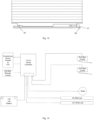
- the electrical source may be the car battery of the vehicle or other power sources and the control signals may be simple switches or a smart control board as shown in Fig. 14 .
- the above-described invention may incorporate additional circuitry to control the color and the brightness of the light sources 17, 18.
- further circuity may be incorporated with any of the embodiments of the present invention to cause the lights 17, 18-to flash or vary in intensity, for example, as the rollable curtain 1 is in movement (opening or closing), when the vehicle brakes or accelerates, etc.
- the end slat 4 may further comprise a lock mechanism, not shown, arranged on the end slat 4, for securing the rollable curtain 1 to the tailgate of the truck.
- Said locking mechanism comprising a handle for opening and closing the rollable curtain 1.
- the cover system is configured to be remotely controlled, as shown in Fig. 14 , by means of a remote-control element or a mobile application installed in a smartphone, or locally controlled by an end slat actuator.
- a smart controller controls lights 17, 18 and any other electric elements arranged on the cover assembly, such as the electric motor, may receive signals from the sensors 19, adjust the brightness of the lights and control the lock mechanism.
Landscapes
- Engineering & Computer Science (AREA)
- Mechanical Engineering (AREA)
- Operating, Guiding And Securing Of Roll- Type Closing Members (AREA)
- Vehicle Step Arrangements And Article Storage (AREA)
- Electric Cable Arrangement Between Relatively Moving Parts (AREA)
Abstract
Description
- The invention relates to a cover assembly for the truck bed of a pick-up type vehicle, and in particular to a cover assembly comprising a rollable curtain and a plurality of cable guiding elements for supporting and guiding cable wires during winding and unwinding of the curtain, to provide a wired connection between stationary and moving or rolling elements.
- Truck bed covers are commonly used with pick-up trucks and like vehicles with cargo areas that are substantially exposed. There are known different types of covers (roll-up covers, folding covers, retractable covers, one-piece solid covers, etc.) for providing a more secure, weather-protected storage.
- The design and use of retractable roll-up truck bed covers with open bed pickup trucks is well known. Conventional retractable roll-up truck bed covers commonly include a rollable curtain formed of a plurality of individual slats hingedly connected to form a slat array. The hinged connection of individual slats enables the slat array to form a continuous cover that, once mounted in a pair of side rails, can be either completely or partially extended or retracted and stored in a rolled-up configuration inside a housing box.
- Covers, and particularly roll-up covers, comprise moveable and rollable elements and sometimes it is desirable to provide an electric wired connection to said elements i.e., to power light fixtures, to communicate with sensors, etc.
- Roll-up covers including an electric wired connection mounted by running a plurality of cable wires in the side rails comprised within the roll-up covers are known.
- However, due to the moveable/rollable aspect of the curtain of the roll-up covers, wired side rails of said covers are not able to provide a continuous connection between electric elements arranged on the rollable curtain and stationary elements, with respect to the housing box of the cover or with respect to the vehicle, while the curtain is operable, i.e., in movement.
- Therefore, there remains a need for a cover assembly and more precisely a roll-up cover, to be able to provide a wired connection and allow power to be provided to moving parts of the cover, and more precisely to parts of the roll-up cover curtain, to be used for multiple purposes, such as for effectively illuminating portions or the entire length of the truck bed, for including light signals, either decorative or functional, sensors, electric actuators, etc.
- In accordance with the invention a cover assembly for a pickup truck bed is provided. The cover assembly comprises a rollable curtain for selectively extending to at least partially cover the pickup truck bed and at least partially retracting to form a roll to be stored inside a housing box. The rollable curtain is formed of a plurality of adjacent transverse panels or slats that are hingedly connected to one another and an end slat.
- According to an aspect of the invention, a plurality of cable guiding elements are mounted to at least part of the plurality of adjacent transverse panels for supporting and guiding cable wires in a defined manner during winding and unwinding of the curtain in such a manner that as the curtain is extended over the pickup truck bed the cable wires are guided and supported, without stretching, along at least one portion of the transverse panels and as the flexible cover is retracted the cable guiding elements guide and support the cable wires to form part of the roll, in an orderly manner, such that upon winding of the curtain the cable wires are wound in a circular manner without bending.
- Hence, the cable guiding elements are designed to avoid stretching or bending of the cable when the cable is wound (rolled) in the housing box and/or when the cover is extended.
- The cable guiding elements are configured to receive cable wires therethrough, from a stationary part of the cover assembly (i.e., parts mounted on the housing box) to different movable or rollable parts of the movable or rollable curtain (i.e., parts mounted on the rollable curtain, transverse panels, end slat) while protecting the cable wires from external damage, minimizing abrasion of the cables and avoiding bending of the cables when the curtain is wound.
- According to another aspect of the invention, the cover assembly comprises a light source arranged on one or more of the plurality of adjacent transverse panels, for effectively illuminating the truck bed of a pick-up type vehicle.
- According to a further aspect of the invention, the cover assembly may also comprise, arranged on the plurality of adjacent transverse panels and/or the end slat, light signals or sensor-means (pressure sensor-means, light sensor-means, extra brake lamp, emergency lamp, obstacle sensors, interior lamps etc.) that may be powered by means of the cable wires.
- Additional objects and advantages of the invention will become apparent to those skilled in the art upon reference to the detailed description taken in conjunction with the provided figures.
- Non-limiting examples of the present disclosure will be described in the following, with reference to the appended drawings, in which
-
Fig. 1a shows a fully extended cover assembly according to an embodiment of the invention. -
Fig. 1b is a detailed view of part of the cover assembly ofFig. 1a , showing the cable guiding elements according to one embodiment of the invention. -
Fig. 2 is a front perspective view of a cable guiding element according to an embodiment of the present invention. -
Fig. 3 is a back perspective view of the cable guiding element ofFig. 2 . -
Fig. 4 is a partial top perspective view of the cover assembly according to one embodiment of the present invention. -
Fig. 5 is a partial top perspective view of the cover assembly according to another embodiment of the present invention. -
Fig. 6 is a partial exploded top view of the cover assembly according to an embodiment of the present invention. -
Fig. 7 is a partial bottom perspective view of the cover assembly according to an embodiment of the present invention. -
Fig. 8 is a partial exploded bottom perspective view of the cover assembly according to an embodiment of the present invention. -
Fig. 9 is a partial exploded view of part of the cover assembly according to an embodiment of the present application. -
Fig. 10 is a partial exploded view of part of the cover assembly according to an embodiment of the present application. -
Fig. 11 is a partial side perspective view of the cover assembly in a wound position, including a cable wire. -
Fig. 12 is a partial side view of the cover assembly in a wound position, including a cable wire. -
Fig. 13 is a partial top view cover assembly of the cover system according to one embodiment of the present invention wherein the end slat comprises a light signal and sensor-means. -
Fig. 14 shows a wiring diagram of the cover assembly according to an embodiment of the invention. -
Fig. 15 is a cross sectional front view of a housing box in accordance with an embodiment of the present invention, wherein the rollable curtain is in a fully retracted position. - With reference to
Fig. 1a , a cover assembly for the truck bed of a pick-up type vehicle according to the invention comprises arollable curtain 1 formed of a plurality of adjacenttransverse panels 2, which are continuously connected along their transverse length byhinge joints 3, and anend slat 4, saidrollable curtain 1 coupled at one end to a transverse rotatable shaft, comprised within ahousing box 21, to allow winding and unwinding thereon. - The cover assembly further comprises a plurality of
cable guiding elements 5, as shown inFig. 1b , mounted to at least part of the plurality of the adjacenttransverse panels 2 and configured to receive cable wires therethrough for providing a wired connection to therollable curtain 1, such that the cable wires can be supported and guided in a defined manner along at least one longitudinal length of therollable curtain 1 during winding and unwinding of the later, providing a wired connection between elements (17, 18, 19) arranged on individualtransverse panels 2 and/or the end slat 4 and stationary elements, i.e. elements mounted on thehousing box 21 of the cover assembly. - The term longitudinal is to be understood as a direction parallel to a travel direction of the vehicle.
- The term transverse is to be understood as a direction transverse to a travel direction of the vehicle.
- The term cable wire is to be understood as any type of cable designed for applications ranging from transmission of data to power supply, such as USB cables, single wire cables, multi-wire cables, coaxial cables, transmission cables, optical-fiber cables, etc.
- In a preferred embodiment of the present invention, as shown in
Figs. 4 and6 to 12 in addition toFigs. 1a and 1b , each one of the plurality of adjacenttransverse panels 2 has a cable guidingelement 5 mounted to one or both of its longitudinal ends. In this manner cable wires can either be arranged along only one longitudinal side of therollable curtain 1 or along both opposed longitudinal sides of therollable curtain 1, allowing for different cable routing arrangements. - Alternatively, the
cable guiding elements 5 may be mounted to only part of the plurality of adjacenttransverse panels 2, to one or both of its longitudinal ends, as shown inFig. 5 . - In one embodiment of the present invention, adjacent
transverse panels 2, may have a cable guidingelement 5 mounted to opposed longitudinal ends, respectively. - In other embodiments, the
cable guiding elements 5 may be mounted or attached at an interior position of the adjacenttransverse panels 2 or may be integrated in the design of thetransverse panels 2. - A number of suitable configurations for the guiding
elements 5 are contemplated. - Contemplated configurations are particularly suitable for receiving cable wires therethrough, allowing cable wires to be wound in the
housing box 21, along with therollable curtain 1, in a circular manner without stretching and avoiding bending of the wires when therollable curtain 1 is extended. - In the illustrated configurations, the
cable guiding elements 5 comprise aninner wall 5a, anouter wall 5b, atop wall 5c, abottom wall 5d, adistal end 5e and aproximal end 5f defining a throughchannel 6 over the entire length of thecable guiding elements 5 for cable wires to be supported and guided as they pass longitudinally through thecable guiding elements 5, as shown inFigs 2 and 3 . - The
cable guiding elements 5 are arranged on therollable curtain 1 in assembled relation such that theproximal end 5f of a cable guidingelement 5 faces thedistal end 5e of a consecutivecable guiding element 5, whether the consecutive guidingelement 5 is mounted to anadjacent panel 2 or mounted to a further removedtransverse panel 2, as shown inFigs. 4 to 11 . - The
distal ends 5e of thecable guiding elements 5 have a design functionally corresponding to the design of theproximal ends 5f, such that when in assembled relation, during winding and unwinding of the rollable curtain1, thedistal end 5e of a cable guidingelement 5 functionally corresponds to theproximal end 5f of a consecutivecable guiding elements 5 to avoid bending of cable wires when the cover is extended and allow winding of the cable wires without stretching. - In one of many equally preferable configurations, the, the
distal end 5e and/or theproximal end 5f of thecable guiding elements 5 is open-ended. - In the preferred embodiment of
Figs. 2 and 3 , thedistal end 5e is open-ended and theproximal end 5f comprises a generally curved portion with anopening 8. - In another equally preferable configuration, the
outer wall 5b extends partially along the longitudinal length of the guidingelement 5, preventing cable wires from slipping out the throughchannel 6. - The
cable guiding elements 5 have a heigh at its proximal anddistal ends elements 5, such that the throughchannel 6 increases in height towards its ends allowing cable wires to be wound in a circular manner without bending, as shown inFigs. 11 and 12 . - In the illustrated embodiments of
Figs. 2 and 3 , thebottom wall 5d comprises twodiagonal segments horizontal segment 11, however, other possible configurations of thebottom wall 5d are also contemplated, thebottom wall 5d may have a curve-shaped configuration, for example. - The cover assembly comprises means 15, for attaching the
cable guiding elements 5 to the adjacenttransverse panels 2. The means for attaching thecable guiding elements 5 to the adjacenttransverse panels 2 may be a threaded bolt orfastener 15, as shown inFig. 10 , or any other suitable attaching means or combination thereof. - In another embodiment, the
housing box 21 may comprisehelical trackways 22 arranged on an inner surface of the side walls thereof, as shown inFig. 15 , to help guide therollable curtain 1 free of excessive frictional resistance upon extending or retracting the same. In such an embodiment, thecable guiding elements 5 may comprise aball bearing 16 to minimize the rolling friction between thetransverse panels 2 and thehelical trackways 22. - The
cable guiding elements 5 may also comprise a plurality of transversely projectingparts Figs.3 and6 , which extend inside thetransverse panels 2 for providing additional attaching means. That is, thecable guiding elements 5 may have a design profile corresponding to the design profile of thetransverse panels 2 for better fit. -
Transversely projecting parts - With specific reference to
Figs. 2 and 3 , theinner wall 5a of thecable guiding elements 5 may comprise apassageway 7 through which cable wires can be passed out of the throughchannel 6 laterally with respect to thecable guiding element 5 to provide a wired connection to elements mounted on to thetransverse panel 2 to which thecable guiding element 5 is mounted to. - In an embodiment of the present invention,
light sources Fig. 13 , may be arranged on one or more of the plurality of adjacenttransverse panels 2 and oriented to direct light into the interior and/or exterior of a truck bed and may be configured for operation by dedicated switches, may be automatically operated upon deployment of therollable curtain 1, may be remotely controlled or may also operate in conjunction with the headlights, parking lights or tail lights of the vehicle. - Alternatively,
light sources -
Light sources transverse panels 2 and theend slat 4. - In a further embodiment of the present invention, as shown in
Fig. 13 , sensor-means 19 may be arranged in theend slat 4, such that when the cover system is motor driven, the cover will automatically stop and reverse upon detecting an obstacle instance. - In a preferred embodiment of the invention, the light source is a
red light 18 that can work as an extra brake light emitting a brake light signal, an emergency light or an extra driving beam light like the rest tailgate lights of the vehicle and/or a safety light during operation of the roll-up cover. - In other embodiments, the
light sources 17, 18may be illuminated when the vehicle and/or the roll-up cover is in operation. - Said lights 17, 18 and sensor-
means 19 may be connected to an electric source on the vehicle, such as the vehicle battery, by means of cable wires guided to specifictransverse panels 2, through thepassageway 7 of the correspondingcable guiding elements 5. The electrical source may be the car battery of the vehicle or other power sources and the control signals may be simple switches or a smart control board as shown inFig. 14 . - The above-described invention may incorporate additional circuitry to control the color and the brightness of the
light sources - In addition, further circuity may be incorporated with any of the embodiments of the present invention to cause the
lights 17, 18-to flash or vary in intensity, for example, as therollable curtain 1 is in movement (opening or closing), when the vehicle brakes or accelerates, etc. - The
end slat 4 may further comprise a lock mechanism, not shown, arranged on theend slat 4, for securing therollable curtain 1 to the tailgate of the truck. Said locking mechanism comprising a handle for opening and closing therollable curtain 1. - The cover system is configured to be remotely controlled, as shown in
Fig. 14 , by means of a remote-control element or a mobile application installed in a smartphone, or locally controlled by an end slat actuator. - In addition, a smart controller controls lights 17, 18 and any other electric elements arranged on the cover assembly, such as the electric motor, may receive signals from the
sensors 19, adjust the brightness of the lights and control the lock mechanism. - While the embodiments have been described in detail in the description, the same is to be considered illustrative and not restrictive in character, being understood that it would be obvious to those skilled in the art that various other changes and modifications may be made without departing from the scope of the disclosure.
Claims (15)
- A cover assembly for the truck bed of a pick-up type vehicle, said assembly comprising a housing box (21) and a rollable curtain (1) formed by a plurality of adjacent transverse panels (2), which are continuously connected along their transverse length by hinge joints (3), and an end slat (4), said curtain (1) coupled at one end to a rotatable transverse shaft to allow winding and unwinding thereon,
characterised in that the assembly further comprises
a plurality of cable guiding elements (5) mounted to at least part of the plurality of adjacent transverse panels (2) and/or the end slat (4) and configured to receive cable wires therethrough for providing a wired connection between electrical elements (17, 18, 19) arranged on the rollable curtain (1) and stationary elements of the housing box (21) such that the cable wires can be supported and guided in a defined manner along at least one longitudinal length of the rollable curtain (1) during winding and unwinding of the later. - The cover assembly according to claim 1, wherein each one of the plurality of adjacent transverse panels (2) has a guiding element (5) mounted to one of its longitudinal ends.
- The cover assembly according to claim 1, wherein each one of the plurality of adjacent transverse panels (2) has a guiding element (5) mounted to both of its longitudinal ends.
- The cover assembly according to claims 1 to 3, wherein the cable guiding elements (5) comprise an inner wall (5a), an outer wall (5b), a top wall (5c), a bottom wall (5d), a distal end (5e) and a proximal end (5f) defining a through channel (6) over the entire length of the cable guiding elements (5) for cable wires to be supported and guided as they pass longitudinally through the cable guiding elements (5).
- The cover assembly according to claim 4, wherein the outer wall (5b) extends partially along the longitudinal length of the guiding element (5) preventing cable wires from slipping out the through channel (6).
- The cover assembly according to claims 4 or 5, wherein the inner wall (5a) comprises a passageway (7) through which a cable wire may be passed out of the through channel (6) laterally with respect to the cable guiding element (5) to provide a wired connection to electrical elements mounted on the transverse panel (2) to which the cable guiding element (5) is mounted to.
- The cover assembly according to claims 4 to 6, wherein the distal end (5e) and/or the proximal end (5f) is open-ended.
- The cover assembly according to claims 4 to 7, wherein the proximal end (5f) comprises a generally curved portion with an opening (8).
- The cover assembly according to claims 4 to 8, wherein the bottom wall (5d) comprises two diagonal segments (9, 10) connected to the respective ends of horizontal segment (11).
- The cover assembly according to preceding claims, wherein the cable guiding elements (5) are arranged on the rollable curtain (1) in assembled relation such that the proximal end (5f) of a cable guiding element (5) faces the distal end (5e) of a consecutive cable guiding element (5).
- The cover assembly according to preceding claims, wherein the guiding elements (5) comprise a plurality of transversely projecting parts (12, 13, 14) which extend inside the transverse panels (2).
- The cover assembly according to preceding claims, wherein the electrical elements comprise one or more of a light source (17, 18) and/ or a sensor means (19) arranged on part of the plurality of adjacent transverse panels (2) or the end slat (4) and connected by cable wires.
- The cover assembly according to claim 12, wherein the light source (17, 18) is a plurality of lighting elements selectively positioned along the length of the transverse panels 2 and/or the end slat 4.
- The cover assembly according to preceding claims, further comprising means (15) for attaching the guiding elements (5) to the adjacent transverse panels (2) and/or the end slat 4.
- The cover assembly according to preceding claims, wherein the housing box (21) comprises helical trackways (22) and each cable guiding element (5) comprises a ball bearing (16) to minimize the rolling friction between the transverse panels (2) and the helical trackways (22).
Priority Applications (12)
| Application Number | Priority Date | Filing Date | Title |
|---|---|---|---|
| PL22185538.0T PL4309931T3 (en) | 2022-07-18 | 2022-07-18 | Cover assembly for truck bed |
| ES22185538T ES3026744T3 (en) | 2022-07-18 | 2022-07-18 | Cover assembly for truck bed |
| RS20250458A RS66789B1 (en) | 2022-07-18 | 2022-07-18 | Cover assembly for truck bed |
| EP22185538.0A EP4309931B1 (en) | 2022-07-18 | 2022-07-18 | Cover assembly for truck bed |
| HUE22185538A HUE071311T2 (en) | 2022-07-18 | 2022-07-18 | Cover structure for truck bed |
| KR1020257004307A KR20250040003A (en) | 2022-07-18 | 2023-07-05 | Cover assembly for truck bed |
| CN202380054056.2A CN119654246A (en) | 2022-07-18 | 2023-07-05 | Protective cover assembly for truck bed |
| US18/995,241 US20260014840A1 (en) | 2022-07-18 | 2023-07-05 | Cover assembly for truck bed |
| PCT/EP2023/068559 WO2024017643A1 (en) | 2022-07-18 | 2023-07-05 | Cover assembly for truck bed |
| AU2023309232A AU2023309232A1 (en) | 2022-07-18 | 2023-07-05 | Cover assembly for truck bed |
| CA3261449A CA3261449A1 (en) | 2022-07-18 | 2023-07-05 | Cover assembly for truck bed |
| ZA2025/00618A ZA202500618B (en) | 2022-07-18 | 2025-01-17 | Cover assembly for truck bed |
Applications Claiming Priority (1)
| Application Number | Priority Date | Filing Date | Title |
|---|---|---|---|
| EP22185538.0A EP4309931B1 (en) | 2022-07-18 | 2022-07-18 | Cover assembly for truck bed |
Publications (3)
| Publication Number | Publication Date |
|---|---|
| EP4309931A1 true EP4309931A1 (en) | 2024-01-24 |
| EP4309931C0 EP4309931C0 (en) | 2025-02-19 |
| EP4309931B1 EP4309931B1 (en) | 2025-02-19 |
Family
ID=82655088
Family Applications (1)
| Application Number | Title | Priority Date | Filing Date |
|---|---|---|---|
| EP22185538.0A Active EP4309931B1 (en) | 2022-07-18 | 2022-07-18 | Cover assembly for truck bed |
Country Status (12)
| Country | Link |
|---|---|
| US (1) | US20260014840A1 (en) |
| EP (1) | EP4309931B1 (en) |
| KR (1) | KR20250040003A (en) |
| CN (1) | CN119654246A (en) |
| AU (1) | AU2023309232A1 (en) |
| CA (1) | CA3261449A1 (en) |
| ES (1) | ES3026744T3 (en) |
| HU (1) | HUE071311T2 (en) |
| PL (1) | PL4309931T3 (en) |
| RS (1) | RS66789B1 (en) |
| WO (1) | WO2024017643A1 (en) |
| ZA (1) | ZA202500618B (en) |
Citations (4)
| Publication number | Priority date | Publication date | Assignee | Title |
|---|---|---|---|---|
| US20160236549A1 (en) * | 2015-02-13 | 2016-08-18 | Andrew Stewart | Cover system for a load bed of a vehicle, and vehicle having a cover system of this type |
| US20160257256A1 (en) * | 2015-03-05 | 2016-09-08 | Fischer Automotive Systems Gmbh & Co. Kg | Blind especially for a storage compartment in a motor vehicle |
| US20180118002A1 (en) * | 2016-11-02 | 2018-05-03 | Retrax Holdings, Llc | Roll-up tonneau cover system with grooved side rails |
| US20200353803A1 (en) * | 2017-02-24 | 2020-11-12 | Bos Automotive Products, Inc. | Stacking rigid cover |
Family Cites Families (14)
| Publication number | Priority date | Publication date | Assignee | Title |
|---|---|---|---|---|
| DE102004020335A1 (en) * | 2004-04-26 | 2005-11-17 | Webasto Ag | Roller blind system for a vehicle roof |
| US7690713B2 (en) * | 2007-02-16 | 2010-04-06 | Trail-R Van Inc. | 4-bar hinge system for load bed cab-high cover adaptation to rear lift access |
| CA3003299C (en) * | 2015-10-30 | 2021-03-16 | Truxmart Ltd. | Tonneau system for use with a pickup truck |
| US10457124B2 (en) * | 2017-08-18 | 2019-10-29 | Roll-N-Lock Corporation | Modified retractable tonneau cover |
| DK179995B1 (en) * | 2018-04-26 | 2020-01-14 | Mountain Top Industries Aps | A drive system and a truck bed comprising a roll-up truck bed cover and the drive system |
| JP7140031B2 (en) * | 2019-03-28 | 2022-09-21 | 株式会社オートネットワーク技術研究所 | wire harness |
| CN211969140U (en) * | 2019-07-24 | 2020-11-20 | 宁波信泰机械有限公司 | Automatic opening and closing carriage covering system for pickup |
| CN114901497B (en) * | 2019-11-21 | 2026-03-27 | 特斯拉公司 | Integrated trunk cover for vehicles |
| CN213205511U (en) * | 2020-06-01 | 2021-05-14 | 南京林业大学 | A roller shutter lifting device for logging cable car |
| DE102022117999A1 (en) * | 2021-08-11 | 2023-03-16 | Magna Closures Inc. | Power operated retractable truck bed closure panel |
| AU2022391641B2 (en) * | 2021-11-17 | 2025-10-23 | Worksport Ltd. | Wire management system for tonneau cover |
| CN114851946A (en) * | 2022-06-09 | 2022-08-05 | 宁波跨途电子科技有限公司 | Solar car cover |
| HUE071283T2 (en) * | 2022-07-18 | 2025-08-28 | Gi Anso 4X4 Club S A | Platform structure for truck loading surface |
| WO2025212083A1 (en) * | 2024-04-02 | 2025-10-09 | Extang Corporation | Heated truck bed cover |
-
2022
- 2022-07-18 RS RS20250458A patent/RS66789B1/en unknown
- 2022-07-18 ES ES22185538T patent/ES3026744T3/en active Active
- 2022-07-18 PL PL22185538.0T patent/PL4309931T3/en unknown
- 2022-07-18 HU HUE22185538A patent/HUE071311T2/en unknown
- 2022-07-18 EP EP22185538.0A patent/EP4309931B1/en active Active
-
2023
- 2023-07-05 CN CN202380054056.2A patent/CN119654246A/en active Pending
- 2023-07-05 AU AU2023309232A patent/AU2023309232A1/en active Pending
- 2023-07-05 US US18/995,241 patent/US20260014840A1/en active Pending
- 2023-07-05 KR KR1020257004307A patent/KR20250040003A/en active Pending
- 2023-07-05 CA CA3261449A patent/CA3261449A1/en active Pending
- 2023-07-05 WO PCT/EP2023/068559 patent/WO2024017643A1/en not_active Ceased
-
2025
- 2025-01-17 ZA ZA2025/00618A patent/ZA202500618B/en unknown
Patent Citations (4)
| Publication number | Priority date | Publication date | Assignee | Title |
|---|---|---|---|---|
| US20160236549A1 (en) * | 2015-02-13 | 2016-08-18 | Andrew Stewart | Cover system for a load bed of a vehicle, and vehicle having a cover system of this type |
| US20160257256A1 (en) * | 2015-03-05 | 2016-09-08 | Fischer Automotive Systems Gmbh & Co. Kg | Blind especially for a storage compartment in a motor vehicle |
| US20180118002A1 (en) * | 2016-11-02 | 2018-05-03 | Retrax Holdings, Llc | Roll-up tonneau cover system with grooved side rails |
| US20200353803A1 (en) * | 2017-02-24 | 2020-11-12 | Bos Automotive Products, Inc. | Stacking rigid cover |
Also Published As
| Publication number | Publication date |
|---|---|
| ES3026744T3 (en) | 2025-06-12 |
| AU2023309232A1 (en) | 2025-01-30 |
| PL4309931T3 (en) | 2025-06-23 |
| ZA202500618B (en) | 2025-10-29 |
| US20260014840A1 (en) | 2026-01-15 |
| EP4309931C0 (en) | 2025-02-19 |
| EP4309931B1 (en) | 2025-02-19 |
| KR20250040003A (en) | 2025-03-21 |
| RS66789B1 (en) | 2025-06-30 |
| HUE071311T2 (en) | 2025-08-28 |
| WO2024017643A1 (en) | 2024-01-25 |
| CA3261449A1 (en) | 2024-01-25 |
| CN119654246A (en) | 2025-03-18 |
Similar Documents
| Publication | Publication Date | Title |
|---|---|---|
| CN111132428B (en) | Lighting device for vehicle | |
| US8016343B2 (en) | Retractable room actuation assembly for recreational vehicle | |
| US7354088B2 (en) | Slidable room assembly and method of installation | |
| US5110172A (en) | Vertically retractable soft or flexible tailgate for a pickup truck | |
| US20260034870A1 (en) | Cover assembly for truck bed | |
| ATE141558T1 (en) | MOTOR VEHICLE COVER ROLLER BLIND WITH GUIDE RAIL ARRANGEMENT | |
| CN110831810A (en) | Protective device for the interior of a motor vehicle | |
| EP4309931B1 (en) | Cover assembly for truck bed | |
| ES3060520T3 (en) | Kits for a truck bed cover assembly | |
| US20200164806A1 (en) | Emerging Side/Rear View Mirror Apparatus | |
| EP3741615B1 (en) | Slide-out room mechanism with cable drive | |
| EP4324702A1 (en) | Automatically deployed tripod for vehicle | |
| EP4686591A1 (en) | A direct driven roller blind assembly | |
| KR20250036203A (en) | Cover assembly for truck bed | |
| AU2013101273B4 (en) | Shade apparatus | |
| KR20020044496A (en) | Room-lamp of moving type for automobile |
Legal Events
| Date | Code | Title | Description |
|---|---|---|---|
| PUAI | Public reference made under article 153(3) epc to a published international application that has entered the european phase |
Free format text: ORIGINAL CODE: 0009012 |
|
| STAA | Information on the status of an ep patent application or granted ep patent |
Free format text: STATUS: THE APPLICATION HAS BEEN PUBLISHED |
|
| AK | Designated contracting states |
Kind code of ref document: A1 Designated state(s): AL AT BE BG CH CY CZ DE DK EE ES FI FR GB GR HR HU IE IS IT LI LT LU LV MC MK MT NL NO PL PT RO RS SE SI SK SM TR |
|
| STAA | Information on the status of an ep patent application or granted ep patent |
Free format text: STATUS: REQUEST FOR EXAMINATION WAS MADE |
|
| 17P | Request for examination filed |
Effective date: 20240722 |
|
| RBV | Designated contracting states (corrected) |
Designated state(s): AL AT BE BG CH CY CZ DE DK EE ES FI FR GB GR HR HU IE IS IT LI LT LU LV MC MK MT NL NO PL PT RO RS SE SI SK SM TR |
|
| GRAP | Despatch of communication of intention to grant a patent |
Free format text: ORIGINAL CODE: EPIDOSNIGR1 |
|
| STAA | Information on the status of an ep patent application or granted ep patent |
Free format text: STATUS: GRANT OF PATENT IS INTENDED |
|
| INTG | Intention to grant announced |
Effective date: 20240916 |
|
| GRAS | Grant fee paid |
Free format text: ORIGINAL CODE: EPIDOSNIGR3 |
|
| GRAA | (expected) grant |
Free format text: ORIGINAL CODE: 0009210 |
|
| STAA | Information on the status of an ep patent application or granted ep patent |
Free format text: STATUS: THE PATENT HAS BEEN GRANTED |
|
| AK | Designated contracting states |
Kind code of ref document: B1 Designated state(s): AL AT BE BG CH CY CZ DE DK EE ES FI FR GB GR HR HU IE IS IT LI LT LU LV MC MK MT NL NO PL PT RO RS SE SI SK SM TR |
|
| REG | Reference to a national code |
Ref country code: GB Ref legal event code: FG4D |
|
| REG | Reference to a national code |
Ref country code: CH Ref legal event code: EP |
|
| REG | Reference to a national code |
Ref country code: DE Ref legal event code: R096 Ref document number: 602022010714 Country of ref document: DE |
|
| REG | Reference to a national code |
Ref country code: IE Ref legal event code: FG4D |
|
| U01 | Request for unitary effect filed |
Effective date: 20250319 |
|
| U07 | Unitary effect registered |
Designated state(s): AT BE BG DE DK EE FI FR IT LT LU LV MT NL PT RO SE SI Effective date: 20250325 |
|
| REG | Reference to a national code |
Ref country code: GR Ref legal event code: EP Ref document number: 20250400761 Country of ref document: GR Effective date: 20250514 |
|
| REG | Reference to a national code |
Ref country code: ES Ref legal event code: FG2A Ref document number: 3026744 Country of ref document: ES Kind code of ref document: T3 Effective date: 20250612 |
|
| PG25 | Lapsed in a contracting state [announced via postgrant information from national office to epo] |
Ref country code: NO Free format text: LAPSE BECAUSE OF FAILURE TO SUBMIT A TRANSLATION OF THE DESCRIPTION OR TO PAY THE FEE WITHIN THE PRESCRIBED TIME-LIMIT Effective date: 20250519 Ref country code: IS Free format text: LAPSE BECAUSE OF FAILURE TO SUBMIT A TRANSLATION OF THE DESCRIPTION OR TO PAY THE FEE WITHIN THE PRESCRIBED TIME-LIMIT Effective date: 20250619 |
|
| PGFP | Annual fee paid to national office [announced via postgrant information from national office to epo] |
Ref country code: RS Payment date: 20250630 Year of fee payment: 4 |
|
| PG25 | Lapsed in a contracting state [announced via postgrant information from national office to epo] |
Ref country code: HR Free format text: LAPSE BECAUSE OF FAILURE TO SUBMIT A TRANSLATION OF THE DESCRIPTION OR TO PAY THE FEE WITHIN THE PRESCRIBED TIME-LIMIT Effective date: 20250219 |
|
| PGFP | Annual fee paid to national office [announced via postgrant information from national office to epo] |
Ref country code: HU Payment date: 20250704 Year of fee payment: 4 |
|
| REG | Reference to a national code |
Ref country code: HU Ref legal event code: AG4A Ref document number: E071311 Country of ref document: HU |
|
| U20 | Renewal fee for the european patent with unitary effect paid |
Year of fee payment: 4 Effective date: 20250728 |
|
| PG25 | Lapsed in a contracting state [announced via postgrant information from national office to epo] |
Ref country code: SM Free format text: LAPSE BECAUSE OF FAILURE TO SUBMIT A TRANSLATION OF THE DESCRIPTION OR TO PAY THE FEE WITHIN THE PRESCRIBED TIME-LIMIT Effective date: 20250219 |
|
| PGFP | Annual fee paid to national office [announced via postgrant information from national office to epo] |
Ref country code: ES Payment date: 20250801 Year of fee payment: 4 |
|
| PGFP | Annual fee paid to national office [announced via postgrant information from national office to epo] |
Ref country code: GR Payment date: 20250718 Year of fee payment: 4 |
|
| PGFP | Annual fee paid to national office [announced via postgrant information from national office to epo] |
Ref country code: PL Payment date: 20250701 Year of fee payment: 4 Ref country code: TR Payment date: 20250711 Year of fee payment: 4 |
|
| PGFP | Annual fee paid to national office [announced via postgrant information from national office to epo] |
Ref country code: CH Payment date: 20250801 Year of fee payment: 4 |
|
| PG25 | Lapsed in a contracting state [announced via postgrant information from national office to epo] |
Ref country code: CZ Free format text: LAPSE BECAUSE OF FAILURE TO SUBMIT A TRANSLATION OF THE DESCRIPTION OR TO PAY THE FEE WITHIN THE PRESCRIBED TIME-LIMIT Effective date: 20250219 |
|
| PGFP | Annual fee paid to national office [announced via postgrant information from national office to epo] |
Ref country code: IE Payment date: 20250728 Year of fee payment: 4 |
|
| PG25 | Lapsed in a contracting state [announced via postgrant information from national office to epo] |
Ref country code: SK Free format text: LAPSE BECAUSE OF FAILURE TO SUBMIT A TRANSLATION OF THE DESCRIPTION OR TO PAY THE FEE WITHIN THE PRESCRIBED TIME-LIMIT Effective date: 20250219 |
|
| PLBE | No opposition filed within time limit |
Free format text: ORIGINAL CODE: 0009261 |
|
| STAA | Information on the status of an ep patent application or granted ep patent |
Free format text: STATUS: NO OPPOSITION FILED WITHIN TIME LIMIT |
|
| 26N | No opposition filed |
Effective date: 20251120 |