EP4309926A1 - Valve group integration module, thermal management system and vehicle - Google Patents
Valve group integration module, thermal management system and vehicle Download PDFInfo
- Publication number
- EP4309926A1 EP4309926A1 EP22815168.4A EP22815168A EP4309926A1 EP 4309926 A1 EP4309926 A1 EP 4309926A1 EP 22815168 A EP22815168 A EP 22815168A EP 4309926 A1 EP4309926 A1 EP 4309926A1
- Authority
- EP
- European Patent Office
- Prior art keywords
- valve
- electric valve
- heat exchanger
- thermal management
- communication
- Prior art date
- Legal status (The legal status is an assumption and is not a legal conclusion. Google has not performed a legal analysis and makes no representation as to the accuracy of the status listed.)
- Pending
Links
Images







Classifications
-
- B—PERFORMING OPERATIONS; TRANSPORTING
- B60—VEHICLES IN GENERAL
- B60H—ARRANGEMENTS OF HEATING, COOLING, VENTILATING OR OTHER AIR-TREATING DEVICES SPECIALLY ADAPTED FOR PASSENGER OR GOODS SPACES OF VEHICLES
- B60H1/00—Heating, cooling or ventilating devices
- B60H1/00485—Valves for air-conditioning devices, e.g. thermostatic valves
-
- B—PERFORMING OPERATIONS; TRANSPORTING
- B60—VEHICLES IN GENERAL
- B60H—ARRANGEMENTS OF HEATING, COOLING, VENTILATING OR OTHER AIR-TREATING DEVICES SPECIALLY ADAPTED FOR PASSENGER OR GOODS SPACES OF VEHICLES
- B60H1/00—Heating, cooling or ventilating devices
- B60H1/00007—Combined heating, ventilating, or cooling devices
-
- B—PERFORMING OPERATIONS; TRANSPORTING
- B60—VEHICLES IN GENERAL
- B60H—ARRANGEMENTS OF HEATING, COOLING, VENTILATING OR OTHER AIR-TREATING DEVICES SPECIALLY ADAPTED FOR PASSENGER OR GOODS SPACES OF VEHICLES
- B60H1/00—Heating, cooling or ventilating devices
- B60H1/00507—Details, e.g. mounting arrangements, desaeration devices
- B60H1/00557—Details of ducts or cables
-
- B—PERFORMING OPERATIONS; TRANSPORTING
- B60—VEHICLES IN GENERAL
- B60H—ARRANGEMENTS OF HEATING, COOLING, VENTILATING OR OTHER AIR-TREATING DEVICES SPECIALLY ADAPTED FOR PASSENGER OR GOODS SPACES OF VEHICLES
- B60H1/00—Heating, cooling or ventilating devices
- B60H1/00642—Control systems or circuits; Control members or indication devices for heating, cooling or ventilating devices
- B60H1/00814—Control systems or circuits characterised by their output, for controlling particular components of the heating, cooling or ventilating installation
- B60H1/00878—Control systems or circuits characterised by their output, for controlling particular components of the heating, cooling or ventilating installation the components being temperature regulating devices
- B60H1/00885—Controlling the flow of heating or cooling liquid, e.g. valves or pumps
Definitions
- the present disclosure relates to the field of vehicle technologies, and specifically, to a valve set integrated module, a thermal management system, and a vehicle.
- a thermal management system is an important part of a vehicle, which can change a temperature environment inside the vehicle so that a driver and passengers can obtain a good driving experience.
- a conventional thermal management system is configured with multiple valves with different functions according to functional requirements. Generally, multiple valves are independently mounted to a pipeline, which causes connection of a system pipeline complex and is not conducive to a vehicle platform design.
- most of the existing valves are electronic valves, and each of the electronic valves needs to be connected to an electrical wiring harness of the vehicle. Since each valve body is separately arranged, a cost of the vehicle wiring harness is relatively high. In the related art, although an integrated valve exists, an integration degree of the existing integrated valve is low, and occupied space is still relatively large.
- a first object of the present disclosure is to provide a valve set integrated module.
- the module integrates multiple valves, which is conducive to simplifying a structure of a vehicle thermal management system, reducing occupied space, and reducing a cost.
- the present disclosure provides a valve set integrated module, which is configured for a thermal management system having multiple preset thermal management modes.
- the module includes:
- the internal flow channel includes an internal flow channel and an external flow channel.
- the body includes a first portion and a second portion.
- the first portion has a first connecting surface.
- the second portion has a second connecting surface.
- the first connecting surface is hermetically connected with the second connecting surface; multiple internal flow channels are arranged inside the first portion; and at least one groove is arranged on the second connecting surface of the second portion, and the groove on the second connecting surface and the first connecting surface jointly define the external flow channel.
- the first electric valve is configured to unblock/block the different thermal management circuits.
- a first end of the first electric valve is in communication with a compressor interface.
- a second end of the first electric valve is selectively communicated with or blocked from an interior heat exchanger inlet interface or an interior condenser inlet interface.
- the second electric valve is configured to throttle the different thermal management circuits.
- a first end of the second electric valve is in communication with a liquid reservoir outlet interface.
- a second end of the second electric valve is selectively communicated with or blocked from an interior evaporator inlet interface or an exterior heat exchanger inlet interface.
- the valve set integrated module further includes a one-way valve arranged on the body.
- An inlet of the one-way valve is in communication with the exterior heat exchanger inlet interface.
- An outlet of the one-way valve is in communication with the second electric valve.
- the valve set integrated module further includes a first solenoid valve arranged on the body.
- a first end of the first solenoid valve is in communication with an exterior heat exchanger outlet interface.
- a second end of the first solenoid valve is in communication with a gas-liquid separator inlet interface.
- the first electric valve is configured to unblock/block and throttle the different thermal management circuits.
- a first end of the first electric valve is in communication with an interior condenser outlet interface.
- a second end of the first electric valve is in communication with the exterior heat exchanger inlet interface.
- the second electric valve is configured to unblock/block the different thermal management circuits.
- a first end of the second electric valve is in communication with the exterior heat exchanger outlet interface.
- a second end of the second electric valve is selectively communicated with the interior evaporator inlet interface or the gas-liquid separator inlet interface.
- the valve set integrated module further includes a first electronic expansion valve arranged on the body.
- a first end of the first electronic expansion valve is in communication with the second electric valve.
- a second end of the first electronic expansion valve is in communication with the interior evaporator inlet interface.
- the valve set integrated module further includes a second solenoid valve arranged on the body.
- a first end of the second solenoid valve is in communication between the interior condenser outlet interface and the first electric valve through a pipeline.
- a second end of the second solenoid valve is in communication between the second electric valve and the first electronic expansion valve through the pipeline.
- the valve set integrated module further includes a second electronic expansion valve arranged on the body.
- a first end of the second electronic expansion valve is in communication with the exterior heat exchanger outlet interface.
- a second end of the second electronic expansion valve is in communication with a battery pack heat exchanger inlet interface arranged on the body.
- valve set integrated module further includes a battery pack heat exchanger arranged on the body.
- An inlet of the battery pack heat exchanger is in communication with the battery pack heat exchanger inlet interface.
- An outlet of the battery pack heat exchanger is connected with a gas-liquid separator.
- a second object of the present disclosure is to provide a thermal management system.
- the system includes an external heat exchange assembly of the thermal management system and the valve set integrated module in any of the above.
- the external heat exchange assembly includes multiple of a compressor, an interior condenser, an exterior heat exchanger, an interior evaporator, a gas-liquid separator, a PTC air heater, a blower, and a PTC water heater.
- a third object of the present disclosure is to provide a vehicle, including the thermal management system.
- multiple internal flow channels are arranged inside the valve set integrated module body to replace the existing connecting pipeline, which is beneficial to simplify the design of the connecting pipeline in the thermal management system.
- a design the body is provided with multiple internal flow channels and multiple valves integrated in the module is conducive to reducing an overall weight of the module and is conducive to a lightweight design of the vehicle.
- different interfaces arranged on the body communicate the internal flow channel with the heat exchange assembly of the external thermal management system to form multiple different thermal management circuits, and the first electric valve and the second electric valve integrated on the module control unblocking/blocking or throttling of the thermal management circuits, to realize multiple preset thermal management modes.
- the directional terms “inside and outside” refer to inside and outside of a relevant part, unless otherwise stated.
- terms “first”, “second” and “third” are only used for distinguishing the description and cannot be understood as indicating or implying relative importance.
- the terms “arrangement”, “communication”, “installation” should be broadly understood, for example, may be fixed connection, may also be detachable connection or integrated connection; or may be a direct connection, an indirect connection through a middle medium, or interior communication between two elements.
- the present disclosure provides a valve set integrated module.
- the valve set integrated module may be configured to implement at least one of multiple preset thermal management modes.
- the preset thermal management modes here include but are not limited to an air conditioning refrigeration mode, a heat pump heating mode, a battery cooling mode, a mode enabling both air conditioning refrigeration and battery cooling, and a dehumidification mode. Specific working principles of the thermal management modes are described in detail later.
- the thermal management system includes an external heat exchange assembly and a valve set integrated module provided in the present disclosure.
- the heat exchange component includes multiple of a compressor 2, an interior condenser 3, an exterior heat exchanger 4, an interior evaporator 5, a gas-liquid separator 6, a PTC air heater 7, a blower 8, and a PTC water heater 9.
- the valve set integrated module includes a body 11, a first electric valve 13, and a second electric valve 14.
- the body 11 is provided with multiple internal flow channels and multiple interfaces configured to communicate the internal flow channels with an external heat exchange assembly of the thermal management system.
- the first electric valve 13 and the second electric valve 14 are arranged on the body 11 and configured to communicate parts of the multiple internal flow channels to form multiple different thermal management circuits.
- the first electric valve 13 and the second electric valve 14 are configured to unblock/block and/or throttle the thermal management circuits to achieve at least one of the multiple preset thermal management modes.
- first electric valve 13 and the second electric valve 14 are configured to unblock/block and/or throttle the thermal management circuits means that the first electric valve 13 and the second electric valve 14 are each an independent valve.
- the first electric valve 13 is used as an example, and the first electric valve 13 may be configured to switch between an unblocking/blocking function and a throttling-induced pressure reducing function.
- the first electric valve can be used as both a solenoid valve and an expansion valve, or the first electric valve 13 may be configured as the expansion valve to throttle different thermal management circuits, or the first electric valve 13 may be configured as a solenoid valve to unblock/block different thermal management circuits.
- the second electric valve 14 may be configured in the same configuration as the first electric valve 13 to achieve the same function. Details are not described herein again.
- the first electric valve 13 and the second electric valve 14 may be any electric valve capable of switching between an unblocking/blocking function and a throttling-induced pressure reducing function.
- the first electric valve 13 is used as an example.
- the first electric valve 13 may include a spherical valve core 1305, an adjustment base 1307, and an execution motor 1301.
- the valve body 1305 is provided with a first channel and a second channel for communicating with each other and for communicating with the internal flow channel.
- the adjustment base 1307 is configured to hold the valve core 1305 in the body 11.
- the adjustment base 1307 is provided with an external thread
- the body 11 is provided with an internal thread for mating with the external thread.
- the execution motor 1301 is configured to drive the valve core 1305 to rotate, and with the rotation of the valve core 1305, the first electric valve 13 can realize the function of switching between an unblocking/blocking function and a throttling-induced pressure reducing function. Further, annular sealing blocks 1304 are arranged on two ends of the first electric valve 13 in a mounting direction to define an interface.
- the execution motor 1301 is mounted to the body 11 through a screw 1302.
- the second electric valve 13 may have the same configuration as the first electric valve 14. Details are not described herein again.
- multiple internal flow channels are arranged inside the valve set integrated module body 11 to replace the existing connecting pipeline, which is beneficial to simplify the design of the connecting pipeline in the thermal management system.
- a design the body is provided with multiple internal flow channels and multiple valves integrated in the module is conducive to reducing an overall weight of the module and is conducive to a lightweight design of the vehicle.
- different interfaces arranged on the body 11 communicate the internal flow channel with the heat exchange assembly of the external thermal management system to form multiple different thermal management circuits, and the first electric valve 13 and the second electric valve 14 integrated on the module control the unblocking/blocking or the throttling of the thermal management circuits, to realize multiple preset thermal management modes.
- the internal flow channel includes an internal flow channel and an external flow channel.
- the body 11 includes a first portion 1101 and a second portion 1102.
- the first portion 1101 has a first connecting surface
- the second portion 1102 has a second connecting surface.
- the first connecting surface is hermetically connected with the second connecting surface.
- Multiple internal flow channels are arranged inside the first portion 1101. At least one groove is arranged on the second connecting surface of the second portion 1102, and the groove on the second connecting surface and the first connecting surface jointly define the external flow channel.
- the multiple internal flow channels are arranged inside the first portion 1101, an external flow channel is defined between the first portion 1101 and the second portion 1102, and the external flow channel and the internal flow channel are selectively communicated through a valve, thereby optimizing an arrangement of the internal flow channel of the body 1, for example, reducing a quantity of internal flow channels and avoiding mutual interference between the internal flow channels.
- the present disclosure provides an exemplary description of the internal flow channel arrangement in the description that follows.
- the first electric valve 13 is configured to unblock/block different thermal management circuits, that is, the first electric valve 13 is configured as a solenoid valve to unblock/block the different thermal management circuits.
- a first end of the first electric valve 13 is in communication with a compressor interface 11009, and a second end of the first electric valve 13 is selectively communicated with or blocked from an interior heat exchanger inlet interface 11005 or an interior condenser inlet interface 11001.
- the selective unblocking/blocking means that the first electric valve 13 is controlled as required to communicate with the interior heat exchanger inlet interface 11005 in some thermal management modes, and with the interior condenser inlet interface 11001 in some other thermal management modes.
- the second electric valve 14 is configured to throttle the different thermal management circuits, that is, the second electric valve 14 is configured as the expansion valve to throttle the different thermal management circuits.
- a first end of the second electric valve 14 is in communication with a liquid reservoir outlet interface 11006.
- a second end of the second electric valve 14 is selectively communicated with or blocked from an interior evaporator inlet interface 11004 or an exterior heat exchanger inlet interface 11005.
- the throttling means the second electric valve 14 is controlled as required to throttle with the interior evaporator inlet interface 11004 in some thermal management modes, and with the exterior heat exchanger inlet interface 11005 in some other thermal management modes.
- valve set integrated module further includes a one-way valve 15 arranged on the body 11.
- An inlet of the one-way valve 15 is in communication with the exterior heat exchanger inlet interface 11005, and an outlet of the one-way valve 15 is in communication with the second electric valve 14.
- an object of exchanging an inlet and an outlet of the exterior heat exchanger can be realized.
- refrigerant flow from the first interface to the second interface.
- the design of the flow channel inside the exterior heat exchanger is adapted to the air-conditioning refrigeration. A state of the refrigerant is different during the cooling and heating process.
- the refrigerant still flows from a first interface of the exterior heat exchanger to a second interface, and the design of the flow channel inside the exterior heat exchanger is not ideal for the refrigerant adaptability in the heating mode. Therefore, the above problems can be solved by exchanging the inlet and the outlet of the exterior heat exchanger.
- valve set integrated module may further include a first solenoid valve 16 arranged on the body 11.
- a first end of the first solenoid valve 16 is in communication with an exterior heat exchanger outlet interface 11008, and a second end of the first solenoid valve 16 is in communication with a gas-liquid separator inlet interface 11003. That is to say, different preset thermal management modes can be further realized by controlling the unblocking/blocking of the first solenoid valve 16.
- the valve set integrated module may further include a second electronic expansion valve 18 arranged on the body 11.
- a first end of the second electronic expansion valve 18 is in communication with an exterior heat exchanger outlet interface 11008, and a second end of the second electronic expansion valve 18 is in communication with a battery pack heat exchanger inlet interface arranged on the body 11.
- the second electronic expansion valve 18 may include an insertion portion 1801 for inserting into the body 11.
- the second electronic expansion valve 18 and the body 11 are fixedly connected by a threaded pin 1802 through a trailing end of the body 11.
- the valve set integrated module may further include a battery pack heat exchanger 19 arranged on the body 11.
- the battery pack heat exchanger 19 can be connected to the body 11 through a screw 1107.
- An inlet of the battery pack heat exchanger 19 is in communication with the battery pack heat exchanger inlet interface, and an outlet of the battery pack heat exchanger 19 is connected to a gas-liquid separator 6.
- connecting joints 1103 and 1105 configured to connect with the first end and the second end of the battery pack heat exchanger 19 and O-rings 1104 and 1106 configured to seal the first end and the second end of the battery pack heat exchanger 19 are respectively arranged on the body 11.
- the battery pack heat exchanger 19 is connected to the body 11 through a threaded fastener.
- thermal management modes that can be realized by the above technical solution are exemplarily described below in conjunction with FIG. 1 to FIG. 13 .
- An outlet 11-102 of the first solenoid valve 16, an outlet 1901 of the battery pack heat exchanger 19, an interface 11-101, an interior evaporator inlet interface 11002, and the gas-liquid separator inlet interface 11003 communicate to form a first internal flow channel 11-1.
- An inlet 11-201 of the second electronic expansion valve 16, the liquid reservoir outlet interface 11006, and an interface 11-202 are communicated to form a second internal flow channel 11-2.
- An outlet of the second electronic expansion valve 16 and an inlet 1902 of the battery pack heat exchanger are communicated to form a third internal flow channel 11-3.
- An inlet of the second electric valve 14 and the condenser outlet interface 11006 are communicated to form a fourth internal flow channel 11-4.
- An outlet of the second electric valve 14 and the exterior heat exchanger inlet interface 11005 are communicated to form a fifth internal flow channel 11-5.
- An outlet of the first electric valve 13, an inlet 11-601 of the second solenoid valve 16 and the exterior heat exchanger outlet interface 11008 are communicated to form a sixth internal flow channel 11-6.
- a PT high pressure interface and the compressor outlet re communicated to form a seventh internal flow channel 11-7.
- the multiple internal flow channels formed above may be partially used as the internal flow channel and partially used as the external flow channel as required.
- a part between the outlet 11-102 of the first solenoid valve 16 and the interface 11-101 in the first internal flow channel 11-1 and the second internal flow channel may be configured as the external flow channels.
- an extending direction of the external flow channel can be specifically set according to the needs of avoiding interference, and the like, which is not limited here, and the other internal flow channels are the internal flow channels.
- Air-conditioning refrigeration mode
- the compressor 2 discharges a high-temperature and high-pressure gaseous refrigerant, which passes through the connecting pipeline and enters the first electric valve 13 through the compressor outlet interface 11009.
- the first electric valve 13 maintains the seventh internal flow channel 11-7 and the sixth internal flow channel 11-6 in communication, and flows out of the valve set integrated module through the exterior heat exchanger outlet interface 11008.
- the refrigerant flowing out of the module enters the exterior heat exchanger 4 through the connecting pipeline for heat exchange, and the refrigerant flowing out of the exterior heat exchanger 4 passes through the exterior heat exchanger inlet interface 11005 and enters the one-way valve 15 through the connecting pipeline.
- the refrigerant flowing through the one-way valve 15 passes through the reservoir inlet interface 11007 and communicates with the reservoir 10 through the connecting pipeline, so that the refrigerant enters the reservoir 10.
- the refrigerant flowing out of the reservoir 10 passes through the liquid reservoir outlet interface 11006 and enters the second electric valve 14 through the connecting line.
- the second electric valve 14 maintains the fourth internal flow channel 11-4 in communication with the interior evaporator inlet interface 11004 and realizes throttling-induced pressure reduction, so that the refrigerant enters the interior evaporator 5 to absorb ambient heat for evaporation.
- the cooled ambient temperature blows cold air into the member compartment through the blower 8 to achieve cooling.
- the refrigerant flowing out of the interior evaporator 5 passes through the interior evaporator outlet interface 11002 and enters the valve set integrated module through the connecting pipeline, passes through the PT low pressure sensor 12 and then enters the gas-liquid separator 6 through the gas-liquid separator inlet 11003, and finally returns to the compressor 2, thereby completing an air conditioning refrigeration mode cycle.
- the compressor 2 discharges a high-temperature and high-pressure gaseous refrigerant, which passes through the connecting pipeline and enters the first electric valve 13 through the compressor outlet interface 11009.
- the first electric valve 13 maintains the seventh internal flow channel 11-7 in communication with the interior condenser inlet interface 11001.
- the refrigerant flowing out of the module enters the interior condenser through the connecting pipeline to release heat, the interior condenser 3 releases heat and combines with the PTC air heater 7, and then blows the hot air into the vehicle through the blower 8 to heat the vehicle.
- the refrigerant is exothermic and liquefied in the interior condenser 3, and then flows into the reservoir 10 through the connecting pipeline for storage.
- the refrigerant flowing out of the reservoir 10 passes through the liquid reservoir outlet interface 11006 on the module and enters the second electric valve 14 through the connecting line.
- the second electric valve maintains the fourth internal flow channel 11-4 in communication with the fifth internal flow channel 11-5, so that the refrigerant flows to the exterior heat exchanger inlet interface 11005 through the interface 11-501.
- the refrigerant flowing out of the module communicates with the exterior heat exchanger 4 through the connecting pipeline, and enters the exterior heat exchanger 4 for heat exchange.
- the refrigerant flowing out of the exterior heat exchanger 4 passes through the exterior heat exchanger outlet interface 11008 and enters the first solenoid valve 16 through the connecting pipe. In this case, the first solenoid valve 16 is in an open state.
- the refrigerant flowing out of the first solenoid valve outlet 11-102 passes through the first internal flow channel 11-1, and passes through the interface 11-103 of the PT low pressure sensor 12 through the gas-liquid separator inlet interface 11003, and is connected to the gas-liquid separator through the connecting line 6 and finally back to the compressor 2, thereby completing a heat pump heating mode cycle.
- the compressor 2 discharges a high-temperature and high-pressure gaseous refrigerant, which passes through the connecting pipeline and enters the first electric valve 13 through the compressor outlet interface 11009.
- the first electric valve 13 maintains the seventh internal flow channel 11-7 and the sixth internal flow channel 11-6 in communication, and flows out of the valve set integrated module through the exterior heat exchanger outlet interface 11008.
- the refrigerant flowing out of the module enters the exterior heat exchanger 4 through the connecting pipeline for heat exchange, and the refrigerant flowing out of the exterior heat exchanger 4 enters the one-way valve 15 through the connecting pipeline by the exterior heat exchanger inlet interface 11005.
- the refrigerant flowing through the one-way valve 15 passes through the reservoir inlet interface 11007 and communicates with the reservoir 10 through the connecting pipeline, so that the refrigerant enters the reservoir 10.
- the refrigerant flowing out of the reservoir 10 passes through the liquid reservoir outlet interface 11006 and enters the second electric valve 14 through the connecting line.
- the second electric valve 14 maintains the fourth internal flow channel 11-4 in communication with the interior evaporator inlet interface 11004 and realizes throttling-induced pressure reduction, so that the refrigerant enters the interior evaporator 5.
- the refrigerant absorbs heat in the interior evaporator 5 and then cools, circulates the indoor air with the interior evaporator 5 through the blower 8, and the indoor water vapor condenses when passing through the outside of the interior evaporator 5 to achieve the function of dehumidification.
- the compressor 2 discharges a high-temperature and high-pressure gaseous refrigerant, which passes through the connecting pipeline and enters the first electric valve 13 through the compressor outlet interface 11009.
- the first electric valve 13 maintains the seventh internal flow channel 11-7 and the sixth internal flow channel 11-6 in communication, and flows out of the valve set integrated module through the exterior heat exchanger outlet interface 11008.
- the refrigerant flowing out of the module enters the exterior heat exchanger 4 through the connecting pipeline for heat exchange, and the refrigerant flowing out of the exterior heat exchanger 4 enters the one-way valve 15 through the connecting pipeline by the exterior heat exchanger inlet interface 11005.
- the refrigerant flowing through the one-way valve 15 communicates with the reservoir 10 through the connecting pipeline through the reservoir inlet interface 11007, so that the refrigerant enters the reservoir 10.
- the refrigerant flowing out of the reservoir 10 passes through the liquid reservoir outlet interface 11006 and flows into the module through the connecting line, and enters the battery pack heat exchanger 19 after being vaporized through the second electronic expansion valve 18.
- the low-temperature refrigerant exchanges heat with the water circuit to cool the battery pack.
- the compressor 2 discharges a high-temperature and high-pressure gaseous refrigerant, which passes through the connecting pipeline and enters the first electric valve 13 through the compressor outlet interface 11009.
- the first electric valve 13 maintains the seventh internal flow channel 11-7 and the sixth internal flow channel 11-6 in communication, and flows out of the valve set integrated module through the exterior heat exchanger outlet interface 11008.
- the refrigerant flowing out of the module enters the exterior heat exchanger 4 through the connecting pipeline for heat exchange, and the refrigerant flowing out of the exterior heat exchanger 4 enters the one-way valve 15 through the connecting pipeline by the exterior heat exchanger inlet interface 11005.
- the refrigerant flowing through the one-way valve 15 passes through the reservoir inlet interface 11007 and communicates with the reservoir 10 through the connecting pipeline, so that the refrigerant enters the reservoir 10.
- the refrigerant flowing out of the reservoir 10 passes through the liquid reservoir outlet interface 11006 and enters the second electric valve 14 through the connecting line.
- the second electric valve 14 maintains the fourth internal flow channel 11-4 in communication with the interior evaporator inlet interface 11004 and realizes throttling-induced pressure reduction, so that the refrigerant enters the interior evaporator 5 to absorb the ambient heat for evaporation.
- the cooled ambient temperature blows cold air into the member compartment through the blower 8 to achieve cooling.
- the second electronic expansion valve 18 is opened, the vaporized refrigerant enters the battery pack heat exchanger 19, and the low-temperature refrigerant exchanges heat with the water circuit to cool the battery pack.
- the first electric valve 13 is configured to unblock/block and throttle different thermal management circuits. That is to say, the first electric valve 13 is configured to be switchable between an unblocking/blocking position and a throttling position, or the first electric valve 13 can be configured as a solenoid valve and as an expansion valve.
- a first end of the first electric valve 13 is in communication with an interior condenser outlet interface 11010.
- a second end of the first electric valve 13 is in communication with the exterior heat exchanger inlet interface 11005.
- the second electric valve 14 is configured to unblock/block the different thermal management circuits, that is, the second electric valve 14 is configured as the solenoid valve to unblock/block the different thermal management circuits.
- a first end of the second electric valve 14 is in communication with the exterior heat exchanger outlet interface 11008.
- a second end of the second electric valve 14 is selectively communicated with the interior evaporator inlet interface 11004 or the gas-liquid separator inlet interface 11003.
- the valve set integrated module further includes a first electronic expansion valve 17 arranged on the body 11. A first end of the first electronic expansion valve 17 is in communication with the second electric valve 14, and a second end of the first electronic expansion valve 17 is in communication with the interior evaporator inlet interface 11004.
- the valve set integrated module further includes a second solenoid valve 20 arranged on the body 11. A first end of the second solenoid valve 20 is in communication between the interior condenser outlet interface 10010 and the first electric valve 13 through a pipeline. A second end of the second solenoid valve 20 is in communication between the second electric valve 14 and the first electronic expansion valve 17 through the pipeline.
- the valve set integrated module may further include a second electronic expansion valve 18 arranged on the body 11.
- a first end of the second electronic expansion valve 18 is in communication with an exterior heat exchanger outlet interface 11008, and a second end of the second electronic expansion valve 18 is in communication with a battery pack heat exchanger inlet interface arranged on the body 11.
- the valve set integrated module may further include a battery pack heat exchanger 19 arranged on the body 11. An inlet of the battery pack heat exchanger 19 is in communication with the battery pack heat exchanger inlet interface, and an outlet of the battery pack heat exchanger 19 is connected to a gas-liquid separator 6.
- thermal management modes that can be realized by the above technical solution are exemplarily described below in conjunction with FIG. 14 to FIG. 23 .
- An outlet 11-101' of the second electric valve 14, an outlet 11-102' of the second solenoid valve 20, an outlet 11-103' of the first electronic expansion valve 17, and the second electronic expansion valve 18 inlet are communicated to form first internal flow channel 11-1'.
- An outlet of the second electronic expansion valve 18 and an inlet 1902 of the battery pack heat exchanger are communicated through the interface 11-201' to form a second internal flow channel 11-2'.
- An inlet 11-701' of the first electric valve 13 communicates with an inlet of the second solenoid valve 20, that is, the interior condenser outlet interface 11010, to form a fifth inner flow channel 11-5'.
- the multiple internal flow channels formed above may be partially used as the internal flow channel and partially used as the external flow channel as required.
- the first internal flow channel 11-1' may be configured as the external flow channel.
- an extending direction of the external flow channel can be specifically set according to the needs of avoiding interference, and the like, which is not limited here, and the other internal flow channels are the internal flow channels.
- Air-conditioning refrigeration mode
- the compressor 2 discharges a high-temperature and high-pressure gaseous refrigerant and enters the interior condenser 3. After the refrigerant is exothermic and liquefied in the interior condenser 3, the refrigerant passes through the interior condenser outlet interface 11010 and enters the first electric valve 13.
- the first electric valve 13 is switched to a solenoid valve and is in an open state, and an interface 11-701' of a first inner flow channel 11-7' is maintained in communication with an outlet of the first electric valve 13, that is, the exterior heat exchanger inlet 11005.
- the refrigerant enters the exterior heat exchanger 4 through the connecting line, and the refrigerant flowing out of the exterior heat exchanger 4 passes through the exterior heat exchanger outlet interface 11008 and enters the second electric valve 14 through the connecting line.
- the second electric valve 14 maintains the interior evaporator inlet interface 11008 in communication with an outlet 11-101' of the second electric valve 14, and is communicated with an inlet 11-103' of the first electronic expansion valve 17 through the first inner flow channel 11-1'.
- the refrigerant passes through the interior evaporator inlet interface 11004 and enters the interior evaporator 5 through the connecting pipeline to absorb the ambient heat for evaporation.
- the cooled ambient temperature blows cold air into the crew compartment through the blower 8 to cool.
- the refrigerant flowing out of the interior evaporator 5 passes through the interior evaporator outlet interface 11002 and enters the valve set integrated module through the connecting pipeline, passes through the PT low pressure sensor 12 interface and enters the third inner flow channel 11-3' through the fourth inner flow channel 11-4', and passes through the gas-liquid separator inlet 11003 and enters the gas-liquid separator 6, and finally returns to the compressor 2, thereby completing an air conditioning refrigeration mode cycle.
- the compressor 2 discharges a high-temperature and high-pressure gaseous refrigerant, and enters the interior condenser 3 to release heat.
- the interior condenser 3 releases heat and combines with the PTC air heater 7, and then blows the hot air into the vehicle through the blower 8 to heat the vehicle.
- the refrigerant passes through the interior condenser outlet interface 11010 and enters the first electric valve 13.
- the first electric valve 13 is switched to an expansion valve for use, and an interface 11-701' of a first inner flow channel 11-7' is maintained in communication with an outlet of the first electric valve 13, that is, the exterior heat exchanger inlet interface 11005.
- the refrigerant after throttling-induced pressure reduction enters the exterior heat exchanger 4 through the connecting pipeline.
- the refrigerant flowing out of the exterior heat exchanger 4 passes through the exterior heat exchanger outlet interface 11008 and enters the second electric valve 14 through the connecting line.
- the second electric valve 14 maintains the exterior heat exchanger outlet interface 11008 in communication with the third inner flow channel 11-3', is connected to the gas-liquid separator 6 through the gas-liquid separator inlet 11003, and finally returns to the compressor 2, thereby completing a heat pump heating mode cycle.
- the compressor 2 discharges a high-temperature and high-pressure gaseous refrigerant and enters the interior condenser 3. After the refrigerant is exothermic and liquefied in the interior condenser 3, the refrigerant passes through the interior condenser outlet interface 11010 and enters the first electric valve 13.
- the first electric valve 13 is switched to a solenoid valve and is in an open state, and an interface 11-701' of a first inner flow channel 11-7' is maintained in communication with an outlet of the first electric valve 13, that is, the exterior heat exchanger inlet interface 11005.
- the refrigerant enters the exterior heat exchanger 4 through the connecting line, and the refrigerant flowing out of the exterior heat exchanger 4 passes through the exterior heat exchanger outlet interface 11008 and enters the second electric valve 14 through the connecting line.
- the second electric valve 14 maintains the interior evaporator inlet interface 11008 in communication with an outlet 11-101' of the second electric valve 14, and is communicated with an inlet 11-103' of the first electronic expansion valve 17 through the first inner flow channel 11-1'.
- the refrigerant passes through the interior evaporator inlet interface 11004 and enters the interior evaporator 5 through the connecting pipeline.
- the refrigerant absorbs heat in the interior evaporator 5 and then cools, circulates the indoor air with the interior evaporator 5 through the blower 8, and the indoor water vapor condenses when passing through the outside of the interior evaporator 5 to achieve the function of dehumidification.
- the compressor 2 discharges a high-temperature and high-pressure gaseous refrigerant and enters the interior condenser 3. After the refrigerant is exothermic and liquefied in the interior condenser 3, the refrigerant passes through the interior condenser outlet interface 11010 and enters the first electric valve 13.
- the first electric valve 13 is switched to a solenoid valve and is in an open state, and an interface 11-701' of a first inner flow channel 11-7' is maintained in communication with an outlet of the first electric valve 13, that is, the exterior heat exchanger inlet interface 11005.
- the refrigerant enters the exterior heat exchanger 4 through the connecting line, the refrigerant flowing out of the exterior heat exchanger 4 passes through the exterior heat exchanger outlet interface 11008 and enters the second electric valve 14 through the connecting pipeline, and enters the battery pack heat exchanger 19 after being vaporized through the second electronic expansion valve 18.
- the low-temperature refrigerant exchanges heat with the water circuit to cool the battery pack.
- the compressor 2 discharges a high-temperature and high-pressure gaseous refrigerant and enters the interior condenser 3. After the refrigerant is exothermic and liquefied in the interior condenser 3, the refrigerant passes through the interior condenser outlet interface 11010 and enters the first electric valve 13.
- the first electric valve 13 is switched to a solenoid valve and is in an open state, and an interface 11-701' of a first inner flow channel 11-7' is maintained in communication with an outlet of the first electric valve 13, that is, the exterior heat exchanger inlet interface 11005.
- the refrigerant enters the exterior heat exchanger 4 through the connecting line, and the refrigerant flowing out of the exterior heat exchanger 4 passes through the exterior heat exchanger outlet interface 11008 and enters the second electric valve 14 through the connecting line.
- the second electric valve 14 maintains the interior evaporator inlet interface 11008 in communication with an outlet 11-101' of the second electric valve 14, and is communicated with an inlet 11-103' of the first electronic expansion valve 17 through the first inner flow channel 11-1'.
- the refrigerant passes through the interior evaporator inlet interface 11004 and enters the interior evaporator 5 through the connecting pipeline to absorb ambient heat for evaporation.
- the cooled ambient temperature blows cold air into the member compartment through the blower 8 to achieve cooling.
- the second electronic expansion valve 18 is opened, the vaporized refrigerant enters the battery pack heat exchanger 19, and the low-temperature refrigerant exchanges heat with the water circuit to cool the battery pack.
- a second object of the present disclosure is to provide a thermal management system.
- the system includes an external heat exchange assembly of the thermal management system and the valve set integrated module in any of the above implementations.
- the external heat exchange assembly includes multiple of a compressor 2, an interior condenser 3, an exterior heat exchanger 4, an interior evaporator 5, a gas-liquid separator 6, a PTC air heater 7, a blower 8, and a PTC water heater 9.
- a third object of the present disclosure is to provide a vehicle, which includes the thermal management system, and can realize all preset thermal management modes of the thermal management system. Details are not described herein again.
- the implementations of the present disclosure are described in detail above with reference to the accompanying drawings. However, the present disclosure is not limited to the specific details in the foregoing implementations, multiple simple deformations may be made to the technical solution of the present disclosure within a range of the technical concept of the present disclosure, and these simple deformations fall within the protection scope of the present disclosure.
Landscapes
- Physics & Mathematics (AREA)
- Thermal Sciences (AREA)
- Engineering & Computer Science (AREA)
- Mechanical Engineering (AREA)
- Air-Conditioning For Vehicles (AREA)
- Cooling, Air Intake And Gas Exhaust, And Fuel Tank Arrangements In Propulsion Units (AREA)
- Arrangement Or Mounting Of Propulsion Units For Vehicles (AREA)
- Secondary Cells (AREA)
- Valve Housings (AREA)
- Temperature-Responsive Valves (AREA)
- Steering-Linkage Mechanisms And Four-Wheel Steering (AREA)
Abstract
Description
- The present disclosure claims priority to
Chinese Patent Application No. 202110603393.5, filed on May 31, 2021 - The present disclosure relates to the field of vehicle technologies, and specifically, to a valve set integrated module, a thermal management system, and a vehicle.
- A thermal management system is an important part of a vehicle, which can change a temperature environment inside the vehicle so that a driver and passengers can obtain a good driving experience. A conventional thermal management system is configured with multiple valves with different functions according to functional requirements. Generally, multiple valves are independently mounted to a pipeline, which causes connection of a system pipeline complex and is not conducive to a vehicle platform design. In addition, most of the existing valves are electronic valves, and each of the electronic valves needs to be connected to an electrical wiring harness of the vehicle. Since each valve body is separately arranged, a cost of the vehicle wiring harness is relatively high. In the related art, although an integrated valve exists, an integration degree of the existing integrated valve is low, and occupied space is still relatively large.
- A first object of the present disclosure is to provide a valve set integrated module. The module integrates multiple valves, which is conducive to simplifying a structure of a vehicle thermal management system, reducing occupied space, and reducing a cost.
- In order to achieve the above objective, the present disclosure provides a valve set integrated module, which is configured for a thermal management system having multiple preset thermal management modes. The module includes:
- a body, provided with multiple internal flow channels and multiple interfaces configured to communicate the internal flow channels with an external heat exchange assembly of the thermal management system; and
- a first electric valve and a second electric valve, arranged on the body and configured to communicate parts of the multiple internal flow channels to form multiple different thermal management circuits, where the first electric valve and the second electric valve are configured to unblock/block and/or throttle the thermal management circuits to achieve at least one of the multiple preset thermal management modes.
- Optionally, the internal flow channel includes an internal flow channel and an external flow channel. The body includes a first portion and a second portion. The first portion has a first connecting surface. The second portion has a second connecting surface. The first connecting surface is hermetically connected with the second connecting surface; multiple internal flow channels are arranged inside the first portion; and at least one groove is arranged on the second connecting surface of the second portion, and the groove on the second connecting surface and the first connecting surface jointly define the external flow channel.
- Optionally, the first electric valve is configured to unblock/block the different thermal management circuits. A first end of the first electric valve is in communication with a compressor interface. A second end of the first electric valve is selectively communicated with or blocked from an interior heat exchanger inlet interface or an interior condenser inlet interface. The second electric valve is configured to throttle the different thermal management circuits. A first end of the second electric valve is in communication with a liquid reservoir outlet interface. A second end of the second electric valve is selectively communicated with or blocked from an interior evaporator inlet interface or an exterior heat exchanger inlet interface.
- Optionally, the valve set integrated module further includes a one-way valve arranged on the body. An inlet of the one-way valve is in communication with the exterior heat exchanger inlet interface. An outlet of the one-way valve is in communication with the second electric valve.
- Optionally, the valve set integrated module further includes a first solenoid valve arranged on the body. A first end of the first solenoid valve is in communication with an exterior heat exchanger outlet interface. A second end of the first solenoid valve is in communication with a gas-liquid separator inlet interface.
- Optionally, the first electric valve is configured to unblock/block and throttle the different thermal management circuits. A first end of the first electric valve is in communication with an interior condenser outlet interface. A second end of the first electric valve is in communication with the exterior heat exchanger inlet interface. The second electric valve is configured to unblock/block the different thermal management circuits. A first end of the second electric valve is in communication with the exterior heat exchanger outlet interface. A second end of the second electric valve is selectively communicated with the interior evaporator inlet interface or the gas-liquid separator inlet interface.
- Optionally, the valve set integrated module further includes a first electronic expansion valve arranged on the body. A first end of the first electronic expansion valve is in communication with the second electric valve. A second end of the first electronic expansion valve is in communication with the interior evaporator inlet interface.
- Optionally, the valve set integrated module further includes a second solenoid valve arranged on the body. A first end of the second solenoid valve is in communication between the interior condenser outlet interface and the first electric valve through a pipeline. A second end of the second solenoid valve is in communication between the second electric valve and the first electronic expansion valve through the pipeline.
- Optionally, the valve set integrated module further includes a second electronic expansion valve arranged on the body. A first end of the second electronic expansion valve is in communication with the exterior heat exchanger outlet interface. A second end of the second electronic expansion valve is in communication with a battery pack heat exchanger inlet interface arranged on the body.
- Optionally, the valve set integrated module further includes a battery pack heat exchanger arranged on the body. An inlet of the battery pack heat exchanger is in communication with the battery pack heat exchanger inlet interface. An outlet of the battery pack heat exchanger is connected with a gas-liquid separator.
- A second object of the present disclosure is to provide a thermal management system. The system includes an external heat exchange assembly of the thermal management system and the valve set integrated module in any of the above. The external heat exchange assembly includes multiple of a compressor, an interior condenser, an exterior heat exchanger, an interior evaporator, a gas-liquid separator, a PTC air heater, a blower, and a PTC water heater.
- A third object of the present disclosure is to provide a vehicle, including the thermal management system.
- In the above technical solution, multiple internal flow channels are arranged inside the valve set integrated module body to replace the existing connecting pipeline, which is beneficial to simplify the design of the connecting pipeline in the thermal management system. From the perspective of lightweight, a design the body is provided with multiple internal flow channels and multiple valves integrated in the module is conducive to reducing an overall weight of the module and is conducive to a lightweight design of the vehicle. In addition, different interfaces arranged on the body communicate the internal flow channel with the heat exchange assembly of the external thermal management system to form multiple different thermal management circuits, and the first electric valve and the second electric valve integrated on the module control unblocking/blocking or throttling of the thermal management circuits, to realize multiple preset thermal management modes.
- Other features and advantages of the present disclosure will be described in detail in the following detailed description part.
- The accompanying drawings are intended to provide further understanding of the present disclosure and constitute a part of this specification. The accompanying drawings and the specific implementations below are used together for explaining the present disclosure rather than constituting a limitation to the present disclosure. In the accompanying drawings:
-
FIG. 1 is a schematic diagram of a thermal management system according to an exemplary embodiment of the present disclosure. -
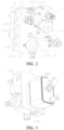
FIG. 2 is an assembly diagram of a valve set integrated module according to an exemplary embodiment of the present disclosure. -
FIG. 3 is an assembly diagram of the valve set integrated module inFIG. 2 from another perspective. -
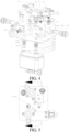
FIG. 4 is an exploded view of a valve set integrated module according to an exemplary embodiment of the present disclosure. -
FIG. 5 is a front view of a valve set integrated module according to an exemplary embodiment of the present disclosure. -
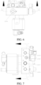
FIG. 6 is a bottom view of a valve set integrated module according to an exemplary embodiment of the present disclosure. -
FIG. 7 is a left side view of a valve set integrated module according to an exemplary embodiment of the present disclosure. -
FIG. 8 is a top view of a valve set integrated module according to an exemplary embodiment of the present disclosure. -
FIG. 9 is a schematic diagram of arrangement of an internal flow channel of a valve set integrated module according to an exemplary embodiment of the present disclosure. -
FIG. 10 is a cross-sectional view of the valve set integrated module inFIG. 6 taken along line A-A. -
FIG. 11 is a cross-sectional view of the valve set integrated module inFIG. 5 taken along line B-B. -
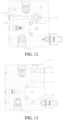
FIG. 12 is a cross-sectional view of the valve set integrated module inFIG. 7 taken along line C-C. -
FIG. 13 is a cross-sectional view of the valve set integrated module inFIG. 8 taken along line D-D. -
FIG. 14 is a schematic diagram of another thermal management system according to an exemplary embodiment of the present disclosure. -
FIG. 15 is an assembly diagram of another valve set integrated module according to an exemplary embodiment of the present disclosure. -
FIG. 16 is an assembly diagram of the valve set integrated module inFIG. 15 from another perspective. -
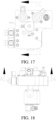
FIG. 17 is a front view of a valve set integrated module according to an exemplary embodiment of the present disclosure. -
FIG. 18 is a bottom view of a valve set integrated module according to an exemplary embodiment of the present disclosure. -
FIG. 19 is a right side view of a valve set integrated module according to an exemplary embodiment of the present disclosure. -
FIG. 20 is a schematic diagram of arrangement of an internal flow channel of a valve set integrated module according to an exemplary embodiment of the present disclosure. -
FIG. 21 is a cross-sectional view of the valve set integrated module inFIG. 18 taken along line A-A. -
FIG. 22 is a cross-sectional view of the valve set integrated module inFIG. 19 taken along line B-B. -
FIG. 23 is a cross-sectional view of the valve set integrated module inFIG. 17 taken along line C-C. - Specific implementations of the present disclosure are described in detail below with reference to the accompanying drawings. It should be understood that the specific implementations described herein are merely used to describe and explain the present disclosure, but are not intended to limit the present disclosure.
- In the present disclosure, without the contrary explanation, the directional terms "inside and outside" refer to inside and outside of a relevant part, unless otherwise stated. In addition, terms "first", "second" and "third" are only used for distinguishing the description and cannot be understood as indicating or implying relative importance. In addition, in the description of the present disclosure, it should be noted that, unless otherwise specified or defined, the terms "arrangement", "communication", "installation" should be broadly understood, for example, may be fixed connection, may also be detachable connection or integrated connection; or may be a direct connection, an indirect connection through a middle medium, or interior communication between two elements. A person of ordinary skill in the art may understand the specific meanings of the foregoing terms in the present disclosure according to specific situations.
- The present disclosure provides a valve set integrated module. The valve set integrated module may be configured to implement at least one of multiple preset thermal management modes. The preset thermal management modes here include but are not limited to an air conditioning refrigeration mode, a heat pump heating mode, a battery cooling mode, a mode enabling both air conditioning refrigeration and battery cooling, and a dehumidification mode. Specific working principles of the thermal management modes are described in detail later.
- To realize the multiple preset thermal management modes listed above, the thermal management system includes an external heat exchange assembly and a valve set integrated module provided in the present disclosure. The heat exchange component includes multiple of a
compressor 2, aninterior condenser 3, anexterior heat exchanger 4, aninterior evaporator 5, a gas-liquid separator 6, aPTC air heater 7, ablower 8, and aPTC water heater 9. - As shown in
FIG. 1 to FIG. 23 , the valve set integrated module provided by the present disclosure includes abody 11, a firstelectric valve 13, and a secondelectric valve 14. Thebody 11 is provided with multiple internal flow channels and multiple interfaces configured to communicate the internal flow channels with an external heat exchange assembly of the thermal management system. The firstelectric valve 13 and the secondelectric valve 14 are arranged on thebody 11 and configured to communicate parts of the multiple internal flow channels to form multiple different thermal management circuits. The firstelectric valve 13 and the secondelectric valve 14 are configured to unblock/block and/or throttle the thermal management circuits to achieve at least one of the multiple preset thermal management modes. - It should be noted that the first
electric valve 13 and the secondelectric valve 14 are configured to unblock/block and/or throttle the thermal management circuits means that the firstelectric valve 13 and the secondelectric valve 14 are each an independent valve. To achieve different preset thermal management modes, the firstelectric valve 13 is used as an example, and the firstelectric valve 13 may be configured to switch between an unblocking/blocking function and a throttling-induced pressure reducing function. It can also be said that the first electric valve can be used as both a solenoid valve and an expansion valve, or the firstelectric valve 13 may be configured as the expansion valve to throttle different thermal management circuits, or the firstelectric valve 13 may be configured as a solenoid valve to unblock/block different thermal management circuits. The secondelectric valve 14 may be configured in the same configuration as the firstelectric valve 13 to achieve the same function. Details are not described herein again. - The first
electric valve 13 and the secondelectric valve 14 may be any electric valve capable of switching between an unblocking/blocking function and a throttling-induced pressure reducing function. The firstelectric valve 13 is used as an example. As described inFIG. 4 , the firstelectric valve 13 may include aspherical valve core 1305, anadjustment base 1307, and anexecution motor 1301. Thevalve body 1305 is provided with a first channel and a second channel for communicating with each other and for communicating with the internal flow channel. Theadjustment base 1307 is configured to hold thevalve core 1305 in thebody 11. For example, theadjustment base 1307 is provided with an external thread, and thebody 11 is provided with an internal thread for mating with the external thread. Theexecution motor 1301 is configured to drive thevalve core 1305 to rotate, and with the rotation of thevalve core 1305, the firstelectric valve 13 can realize the function of switching between an unblocking/blocking function and a throttling-induced pressure reducing function. Further,annular sealing blocks 1304 are arranged on two ends of the firstelectric valve 13 in a mounting direction to define an interface. Theexecution motor 1301 is mounted to thebody 11 through ascrew 1302. The secondelectric valve 13 may have the same configuration as the firstelectric valve 14. Details are not described herein again. - In the above technical solution, multiple internal flow channels are arranged inside the valve set integrated
module body 11 to replace the existing connecting pipeline, which is beneficial to simplify the design of the connecting pipeline in the thermal management system. From the perspective of lightweight, a design the body is provided with multiple internal flow channels and multiple valves integrated in the module is conducive to reducing an overall weight of the module and is conducive to a lightweight design of the vehicle. In addition, different interfaces arranged on thebody 11 communicate the internal flow channel with the heat exchange assembly of the external thermal management system to form multiple different thermal management circuits, and the firstelectric valve 13 and the secondelectric valve 14 integrated on the module control the unblocking/blocking or the throttling of the thermal management circuits, to realize multiple preset thermal management modes. - According to an implementation of the present disclosure, the internal flow channel includes an internal flow channel and an external flow channel. The
body 11 includes afirst portion 1101 and asecond portion 1102. Thefirst portion 1101 has a first connecting surface, and thesecond portion 1102 has a second connecting surface. The first connecting surface is hermetically connected with the second connecting surface. Multiple internal flow channels are arranged inside thefirst portion 1101. At least one groove is arranged on the second connecting surface of thesecond portion 1102, and the groove on the second connecting surface and the first connecting surface jointly define the external flow channel. The multiple internal flow channels are arranged inside thefirst portion 1101, an external flow channel is defined between thefirst portion 1101 and thesecond portion 1102, and the external flow channel and the internal flow channel are selectively communicated through a valve, thereby optimizing an arrangement of the internal flow channel of thebody 1, for example, reducing a quantity of internal flow channels and avoiding mutual interference between the internal flow channels. The present disclosure provides an exemplary description of the internal flow channel arrangement in the description that follows. - In an implementation of the present disclosure, as shown in
FIG. 1 to FIG. 3 , the firstelectric valve 13 is configured to unblock/block different thermal management circuits, that is, the firstelectric valve 13 is configured as a solenoid valve to unblock/block the different thermal management circuits. A first end of the firstelectric valve 13 is in communication with acompressor interface 11009, and a second end of the firstelectric valve 13 is selectively communicated with or blocked from an interior heatexchanger inlet interface 11005 or an interiorcondenser inlet interface 11001. The selective unblocking/blocking means that the firstelectric valve 13 is controlled as required to communicate with the interior heatexchanger inlet interface 11005 in some thermal management modes, and with the interiorcondenser inlet interface 11001 in some other thermal management modes. The secondelectric valve 14 is configured to throttle the different thermal management circuits, that is, the secondelectric valve 14 is configured as the expansion valve to throttle the different thermal management circuits. A first end of the secondelectric valve 14 is in communication with a liquidreservoir outlet interface 11006. A second end of the secondelectric valve 14 is selectively communicated with or blocked from an interiorevaporator inlet interface 11004 or an exterior heatexchanger inlet interface 11005. The throttling means the secondelectric valve 14 is controlled as required to throttle with the interiorevaporator inlet interface 11004 in some thermal management modes, and with the exterior heatexchanger inlet interface 11005 in some other thermal management modes. - Further, the valve set integrated module further includes a one-
way valve 15 arranged on thebody 11. An inlet of the one-way valve 15 is in communication with the exterior heatexchanger inlet interface 11005, and an outlet of the one-way valve 15 is in communication with the secondelectric valve 14. Through this design, an object of exchanging an inlet and an outlet of the exterior heat exchanger can be realized. For example, in the air-conditioning refrigeration mode, refrigerant flow from the first interface to the second interface. In this case, the design of the flow channel inside the exterior heat exchanger is adapted to the air-conditioning refrigeration. A state of the refrigerant is different during the cooling and heating process. In the heating mode, the refrigerant still flows from a first interface of the exterior heat exchanger to a second interface, and the design of the flow channel inside the exterior heat exchanger is not ideal for the refrigerant adaptability in the heating mode. Therefore, the above problems can be solved by exchanging the inlet and the outlet of the exterior heat exchanger. - In addition, the valve set integrated module may further include a
first solenoid valve 16 arranged on thebody 11. A first end of thefirst solenoid valve 16 is in communication with an exterior heatexchanger outlet interface 11008, and a second end of thefirst solenoid valve 16 is in communication with a gas-liquidseparator inlet interface 11003. That is to say, different preset thermal management modes can be further realized by controlling the unblocking/blocking of thefirst solenoid valve 16. - According to an implementation of the present disclosure, to further realize the thermal management mode of battery pack cooling, as shown in
FIG. 1 to FIG. 3 , the valve set integrated module may further include a secondelectronic expansion valve 18 arranged on thebody 11. A first end of the secondelectronic expansion valve 18 is in communication with an exterior heatexchanger outlet interface 11008, and a second end of the secondelectronic expansion valve 18 is in communication with a battery pack heat exchanger inlet interface arranged on thebody 11. The secondelectronic expansion valve 18 may include an insertion portion 1801 for inserting into thebody 11. The secondelectronic expansion valve 18 and thebody 11 are fixedly connected by a threaded pin 1802 through a trailing end of thebody 11. - The valve set integrated module may further include a battery
pack heat exchanger 19 arranged on thebody 11. The batterypack heat exchanger 19 can be connected to thebody 11 through ascrew 1107. An inlet of the batterypack heat exchanger 19 is in communication with the battery pack heat exchanger inlet interface, and an outlet of the batterypack heat exchanger 19 is connected to a gas-liquid separator 6. In a manner for mounting the batterypack heat exchanger 19, connectingjoints pack heat exchanger 19 and O-rings pack heat exchanger 19 are respectively arranged on thebody 11. The batterypack heat exchanger 19 is connected to thebody 11 through a threaded fastener. - The thermal management modes that can be realized by the above technical solution are exemplarily described below in conjunction with
FIG. 1 to FIG. 13 . - In order to facilitate the description of the thermal management mode, the arrangement of the internal flow channels is first exemplarily described here. An outlet 11-102 of the
first solenoid valve 16, anoutlet 1901 of the batterypack heat exchanger 19, an interface 11-101, an interiorevaporator inlet interface 11002, and the gas-liquidseparator inlet interface 11003 communicate to form a first internal flow channel 11-1. An inlet 11-201 of the secondelectronic expansion valve 16, the liquidreservoir outlet interface 11006, and an interface 11-202 are communicated to form a second internal flow channel 11-2. An outlet of the secondelectronic expansion valve 16 and aninlet 1902 of the battery pack heat exchanger are communicated to form a third internal flow channel 11-3. An inlet of the secondelectric valve 14 and thecondenser outlet interface 11006 are communicated to form a fourth internal flow channel 11-4. An outlet of the secondelectric valve 14 and the exterior heatexchanger inlet interface 11005 are communicated to form a fifth internal flow channel 11-5. An outlet of the firstelectric valve 13, an inlet 11-601 of thesecond solenoid valve 16 and the exterior heatexchanger outlet interface 11008 are communicated to form a sixth internal flow channel 11-6. A PT high pressure interface and the compressor outlet re communicated to form a seventh internal flow channel 11-7. The multiple internal flow channels formed above may be partially used as the internal flow channel and partially used as the external flow channel as required. For example, a part between the outlet 11-102 of thefirst solenoid valve 16 and the interface 11-101 in the first internal flow channel 11-1 and the second internal flow channel may be configured as the external flow channels. In addition, an extending direction of the external flow channel can be specifically set according to the needs of avoiding interference, and the like, which is not limited here, and the other internal flow channels are the internal flow channels. - The
compressor 2 discharges a high-temperature and high-pressure gaseous refrigerant, which passes through the connecting pipeline and enters the firstelectric valve 13 through thecompressor outlet interface 11009. In this case, the firstelectric valve 13 maintains the seventh internal flow channel 11-7 and the sixth internal flow channel 11-6 in communication, and flows out of the valve set integrated module through the exterior heatexchanger outlet interface 11008. The refrigerant flowing out of the module enters theexterior heat exchanger 4 through the connecting pipeline for heat exchange, and the refrigerant flowing out of theexterior heat exchanger 4 passes through the exterior heatexchanger inlet interface 11005 and enters the one-way valve 15 through the connecting pipeline. The refrigerant flowing through the one-way valve 15 passes through thereservoir inlet interface 11007 and communicates with thereservoir 10 through the connecting pipeline, so that the refrigerant enters thereservoir 10. The refrigerant flowing out of thereservoir 10 passes through the liquidreservoir outlet interface 11006 and enters the secondelectric valve 14 through the connecting line. The secondelectric valve 14 maintains the fourth internal flow channel 11-4 in communication with the interiorevaporator inlet interface 11004 and realizes throttling-induced pressure reduction, so that the refrigerant enters theinterior evaporator 5 to absorb ambient heat for evaporation. The cooled ambient temperature blows cold air into the member compartment through theblower 8 to achieve cooling. The refrigerant flowing out of theinterior evaporator 5 passes through the interiorevaporator outlet interface 11002 and enters the valve set integrated module through the connecting pipeline, passes through the PTlow pressure sensor 12 and then enters the gas-liquid separator 6 through the gas-liquid separator inlet 11003, and finally returns to thecompressor 2, thereby completing an air conditioning refrigeration mode cycle. - The
compressor 2 discharges a high-temperature and high-pressure gaseous refrigerant, which passes through the connecting pipeline and enters the firstelectric valve 13 through thecompressor outlet interface 11009. In this case, the firstelectric valve 13 maintains the seventh internal flow channel 11-7 in communication with the interiorcondenser inlet interface 11001. The refrigerant flowing out of the module enters the interior condenser through the connecting pipeline to release heat, theinterior condenser 3 releases heat and combines with thePTC air heater 7, and then blows the hot air into the vehicle through theblower 8 to heat the vehicle. The refrigerant is exothermic and liquefied in theinterior condenser 3, and then flows into thereservoir 10 through the connecting pipeline for storage. The refrigerant flowing out of thereservoir 10 passes through the liquidreservoir outlet interface 11006 on the module and enters the secondelectric valve 14 through the connecting line. The second electric valve maintains the fourth internal flow channel 11-4 in communication with the fifth internal flow channel 11-5, so that the refrigerant flows to the exterior heatexchanger inlet interface 11005 through the interface 11-501. The refrigerant flowing out of the module communicates with theexterior heat exchanger 4 through the connecting pipeline, and enters theexterior heat exchanger 4 for heat exchange. The refrigerant flowing out of theexterior heat exchanger 4 passes through the exterior heatexchanger outlet interface 11008 and enters thefirst solenoid valve 16 through the connecting pipe. In this case, thefirst solenoid valve 16 is in an open state. The refrigerant flowing out of the first solenoid valve outlet 11-102 passes through the first internal flow channel 11-1, and passes through the interface 11-103 of the PTlow pressure sensor 12 through the gas-liquidseparator inlet interface 11003, and is connected to the gas-liquid separator through the connectingline 6 and finally back to thecompressor 2, thereby completing a heat pump heating mode cycle. - The
compressor 2 discharges a high-temperature and high-pressure gaseous refrigerant, which passes through the connecting pipeline and enters the firstelectric valve 13 through thecompressor outlet interface 11009. In this case, the firstelectric valve 13 maintains the seventh internal flow channel 11-7 and the sixth internal flow channel 11-6 in communication, and flows out of the valve set integrated module through the exterior heatexchanger outlet interface 11008. The refrigerant flowing out of the module enters theexterior heat exchanger 4 through the connecting pipeline for heat exchange, and the refrigerant flowing out of theexterior heat exchanger 4 enters the one-way valve 15 through the connecting pipeline by the exterior heatexchanger inlet interface 11005. The refrigerant flowing through the one-way valve 15 passes through thereservoir inlet interface 11007 and communicates with thereservoir 10 through the connecting pipeline, so that the refrigerant enters thereservoir 10. The refrigerant flowing out of thereservoir 10 passes through the liquidreservoir outlet interface 11006 and enters the secondelectric valve 14 through the connecting line. The secondelectric valve 14 maintains the fourth internal flow channel 11-4 in communication with the interiorevaporator inlet interface 11004 and realizes throttling-induced pressure reduction, so that the refrigerant enters theinterior evaporator 5. The refrigerant absorbs heat in theinterior evaporator 5 and then cools, circulates the indoor air with theinterior evaporator 5 through theblower 8, and the indoor water vapor condenses when passing through the outside of theinterior evaporator 5 to achieve the function of dehumidification. - The
compressor 2 discharges a high-temperature and high-pressure gaseous refrigerant, which passes through the connecting pipeline and enters the firstelectric valve 13 through thecompressor outlet interface 11009. In this case, the firstelectric valve 13 maintains the seventh internal flow channel 11-7 and the sixth internal flow channel 11-6 in communication, and flows out of the valve set integrated module through the exterior heatexchanger outlet interface 11008. The refrigerant flowing out of the module enters theexterior heat exchanger 4 through the connecting pipeline for heat exchange, and the refrigerant flowing out of theexterior heat exchanger 4 enters the one-way valve 15 through the connecting pipeline by the exterior heatexchanger inlet interface 11005. The refrigerant flowing through the one-way valve 15 communicates with thereservoir 10 through the connecting pipeline through thereservoir inlet interface 11007, so that the refrigerant enters thereservoir 10. The refrigerant flowing out of thereservoir 10 passes through the liquidreservoir outlet interface 11006 and flows into the module through the connecting line, and enters the batterypack heat exchanger 19 after being vaporized through the secondelectronic expansion valve 18. The low-temperature refrigerant exchanges heat with the water circuit to cool the battery pack. - The
compressor 2 discharges a high-temperature and high-pressure gaseous refrigerant, which passes through the connecting pipeline and enters the firstelectric valve 13 through thecompressor outlet interface 11009. In this case, the firstelectric valve 13 maintains the seventh internal flow channel 11-7 and the sixth internal flow channel 11-6 in communication, and flows out of the valve set integrated module through the exterior heatexchanger outlet interface 11008. The refrigerant flowing out of the module enters theexterior heat exchanger 4 through the connecting pipeline for heat exchange, and the refrigerant flowing out of theexterior heat exchanger 4 enters the one-way valve 15 through the connecting pipeline by the exterior heatexchanger inlet interface 11005. The refrigerant flowing through the one-way valve 15 passes through thereservoir inlet interface 11007 and communicates with thereservoir 10 through the connecting pipeline, so that the refrigerant enters thereservoir 10. The refrigerant flowing out of thereservoir 10 passes through the liquidreservoir outlet interface 11006 and enters the secondelectric valve 14 through the connecting line. The secondelectric valve 14 maintains the fourth internal flow channel 11-4 in communication with the interiorevaporator inlet interface 11004 and realizes throttling-induced pressure reduction, so that the refrigerant enters theinterior evaporator 5 to absorb the ambient heat for evaporation. The cooled ambient temperature blows cold air into the member compartment through theblower 8 to achieve cooling. The secondelectronic expansion valve 18 is opened, the vaporized refrigerant enters the batterypack heat exchanger 19, and the low-temperature refrigerant exchanges heat with the water circuit to cool the battery pack. - In another implementation of the present disclosure, as shown in
FIG. 14 to FIG. 16 , the firstelectric valve 13 is configured to unblock/block and throttle different thermal management circuits. That is to say, the firstelectric valve 13 is configured to be switchable between an unblocking/blocking position and a throttling position, or the firstelectric valve 13 can be configured as a solenoid valve and as an expansion valve. A first end of the firstelectric valve 13 is in communication with an interiorcondenser outlet interface 11010. A second end of the firstelectric valve 13 is in communication with the exterior heatexchanger inlet interface 11005. The secondelectric valve 14 is configured to unblock/block the different thermal management circuits, that is, the secondelectric valve 14 is configured as the solenoid valve to unblock/block the different thermal management circuits. A first end of the secondelectric valve 14 is in communication with the exterior heatexchanger outlet interface 11008. A second end of the secondelectric valve 14 is selectively communicated with the interiorevaporator inlet interface 11004 or the gas-liquidseparator inlet interface 11003. - Further, the valve set integrated module further includes a first
electronic expansion valve 17 arranged on thebody 11. A first end of the firstelectronic expansion valve 17 is in communication with the secondelectric valve 14, and a second end of the firstelectronic expansion valve 17 is in communication with the interiorevaporator inlet interface 11004. Optionally, the valve set integrated module further includes asecond solenoid valve 20 arranged on thebody 11. A first end of thesecond solenoid valve 20 is in communication between the interior condenser outlet interface 10010 and the firstelectric valve 13 through a pipeline. A second end of thesecond solenoid valve 20 is in communication between the secondelectric valve 14 and the firstelectronic expansion valve 17 through the pipeline. - According to an implementation of the present disclosure, to further realize the thermal management mode of battery pack cooling, as shown in
FIG. 1 to FIG. 3 , the valve set integrated module may further include a secondelectronic expansion valve 18 arranged on thebody 11. A first end of the secondelectronic expansion valve 18 is in communication with an exterior heatexchanger outlet interface 11008, and a second end of the secondelectronic expansion valve 18 is in communication with a battery pack heat exchanger inlet interface arranged on thebody 11. The valve set integrated module may further include a batterypack heat exchanger 19 arranged on thebody 11. An inlet of the batterypack heat exchanger 19 is in communication with the battery pack heat exchanger inlet interface, and an outlet of the batterypack heat exchanger 19 is connected to a gas-liquid separator 6. - The thermal management modes that can be realized by the above technical solution are exemplarily described below in conjunction with
FIG. 14 to FIG. 23 . - In order to facilitate the description of the thermal management mode, the arrangement of the internal flow channels is first exemplarily described here. An outlet 11-101' of the second
electric valve 14, an outlet 11-102' of thesecond solenoid valve 20, an outlet 11-103' of the firstelectronic expansion valve 17, and the secondelectronic expansion valve 18 inlet are communicated to form first internal flow channel 11-1'. An outlet of the secondelectronic expansion valve 18 and aninlet 1902 of the battery pack heat exchanger are communicated through the interface 11-201' to form a second internal flow channel 11-2'. An outlet of the secondelectric valve 14, that is, anoutlet 1901 of the battery pack heat exchanger connected through 11-301', is communicated with theinlet connection interface 11003 of the gas-liquid separator, a fourth inner flow channel 11-4' and a PT low pressure sensor interface 11-401 'and the interiorevaporator outlet interface 11002 to form a third inner flow channel 11-3'. An inlet 11-701' of the firstelectric valve 13 communicates with an inlet of thesecond solenoid valve 20, that is, the interiorcondenser outlet interface 11010, to form a fifth inner flow channel 11-5'. The multiple internal flow channels formed above may be partially used as the internal flow channel and partially used as the external flow channel as required. For example, the first internal flow channel 11-1' may be configured as the external flow channel. In addition, an extending direction of the external flow channel can be specifically set according to the needs of avoiding interference, and the like, which is not limited here, and the other internal flow channels are the internal flow channels. - The
compressor 2 discharges a high-temperature and high-pressure gaseous refrigerant and enters theinterior condenser 3. After the refrigerant is exothermic and liquefied in theinterior condenser 3, the refrigerant passes through the interiorcondenser outlet interface 11010 and enters the firstelectric valve 13. In this case, the firstelectric valve 13 is switched to a solenoid valve and is in an open state, and an interface 11-701' of a first inner flow channel 11-7' is maintained in communication with an outlet of the firstelectric valve 13, that is, the exteriorheat exchanger inlet 11005. The refrigerant enters theexterior heat exchanger 4 through the connecting line, and the refrigerant flowing out of theexterior heat exchanger 4 passes through the exterior heatexchanger outlet interface 11008 and enters the secondelectric valve 14 through the connecting line. In this case, the secondelectric valve 14 maintains the interiorevaporator inlet interface 11008 in communication with an outlet 11-101' of the secondelectric valve 14, and is communicated with an inlet 11-103' of the firstelectronic expansion valve 17 through the first inner flow channel 11-1'. After the throttling-induced pressure reduction by the firstelectronic expansion valve 17, the refrigerant passes through the interiorevaporator inlet interface 11004 and enters theinterior evaporator 5 through the connecting pipeline to absorb the ambient heat for evaporation. The cooled ambient temperature blows cold air into the crew compartment through theblower 8 to cool. The refrigerant flowing out of theinterior evaporator 5 passes through the interiorevaporator outlet interface 11002 and enters the valve set integrated module through the connecting pipeline, passes through the PTlow pressure sensor 12 interface and enters the third inner flow channel 11-3' through the fourth inner flow channel 11-4', and passes through the gas-liquid separator inlet 11003 and enters the gas-liquid separator 6, and finally returns to thecompressor 2, thereby completing an air conditioning refrigeration mode cycle. - The
compressor 2 discharges a high-temperature and high-pressure gaseous refrigerant, and enters theinterior condenser 3 to release heat. Theinterior condenser 3 releases heat and combines with thePTC air heater 7, and then blows the hot air into the vehicle through theblower 8 to heat the vehicle. After the refrigerant is exothermic and liquefied in theinterior condenser 3, the refrigerant passes through the interiorcondenser outlet interface 11010 and enters the firstelectric valve 13. In this case, the firstelectric valve 13 is switched to an expansion valve for use, and an interface 11-701' of a first inner flow channel 11-7' is maintained in communication with an outlet of the firstelectric valve 13, that is, the exterior heatexchanger inlet interface 11005. The refrigerant after throttling-induced pressure reduction enters theexterior heat exchanger 4 through the connecting pipeline. The refrigerant flowing out of theexterior heat exchanger 4 passes through the exterior heatexchanger outlet interface 11008 and enters the secondelectric valve 14 through the connecting line. In this case, the secondelectric valve 14 maintains the exterior heatexchanger outlet interface 11008 in communication with the third inner flow channel 11-3', is connected to the gas-liquid separator 6 through the gas-liquid separator inlet 11003, and finally returns to thecompressor 2, thereby completing a heat pump heating mode cycle. - The
compressor 2 discharges a high-temperature and high-pressure gaseous refrigerant and enters theinterior condenser 3. After the refrigerant is exothermic and liquefied in theinterior condenser 3, the refrigerant passes through the interiorcondenser outlet interface 11010 and enters the firstelectric valve 13. In this case, the firstelectric valve 13 is switched to a solenoid valve and is in an open state, and an interface 11-701' of a first inner flow channel 11-7' is maintained in communication with an outlet of the firstelectric valve 13, that is, the exterior heatexchanger inlet interface 11005. The refrigerant enters theexterior heat exchanger 4 through the connecting line, and the refrigerant flowing out of theexterior heat exchanger 4 passes through the exterior heatexchanger outlet interface 11008 and enters the secondelectric valve 14 through the connecting line. In this case, the secondelectric valve 14 maintains the interiorevaporator inlet interface 11008 in communication with an outlet 11-101' of the secondelectric valve 14, and is communicated with an inlet 11-103' of the firstelectronic expansion valve 17 through the first inner flow channel 11-1'. After throttling-induced pressure reduction by the firstelectronic expansion valve 17, the refrigerant passes through the interiorevaporator inlet interface 11004 and enters theinterior evaporator 5 through the connecting pipeline. The refrigerant absorbs heat in theinterior evaporator 5 and then cools, circulates the indoor air with theinterior evaporator 5 through theblower 8, and the indoor water vapor condenses when passing through the outside of theinterior evaporator 5 to achieve the function of dehumidification. - The
compressor 2 discharges a high-temperature and high-pressure gaseous refrigerant and enters theinterior condenser 3. After the refrigerant is exothermic and liquefied in theinterior condenser 3, the refrigerant passes through the interiorcondenser outlet interface 11010 and enters the firstelectric valve 13. In this case, the firstelectric valve 13 is switched to a solenoid valve and is in an open state, and an interface 11-701' of a first inner flow channel 11-7' is maintained in communication with an outlet of the firstelectric valve 13, that is, the exterior heatexchanger inlet interface 11005. The refrigerant enters theexterior heat exchanger 4 through the connecting line, the refrigerant flowing out of theexterior heat exchanger 4 passes through the exterior heatexchanger outlet interface 11008 and enters the secondelectric valve 14 through the connecting pipeline, and enters the batterypack heat exchanger 19 after being vaporized through the secondelectronic expansion valve 18. The low-temperature refrigerant exchanges heat with the water circuit to cool the battery pack. - The
compressor 2 discharges a high-temperature and high-pressure gaseous refrigerant and enters theinterior condenser 3. After the refrigerant is exothermic and liquefied in theinterior condenser 3, the refrigerant passes through the interiorcondenser outlet interface 11010 and enters the firstelectric valve 13. In this case, the firstelectric valve 13 is switched to a solenoid valve and is in an open state, and an interface 11-701' of a first inner flow channel 11-7' is maintained in communication with an outlet of the firstelectric valve 13, that is, the exterior heatexchanger inlet interface 11005. The refrigerant enters theexterior heat exchanger 4 through the connecting line, and the refrigerant flowing out of theexterior heat exchanger 4 passes through the exterior heatexchanger outlet interface 11008 and enters the secondelectric valve 14 through the connecting line. In this case, the secondelectric valve 14 maintains the interiorevaporator inlet interface 11008 in communication with an outlet 11-101' of the secondelectric valve 14, and is communicated with an inlet 11-103' of the firstelectronic expansion valve 17 through the first inner flow channel 11-1'. After throttling-induced pressure reduction by the firstelectronic expansion valve 17, the refrigerant passes through the interiorevaporator inlet interface 11004 and enters theinterior evaporator 5 through the connecting pipeline to absorb ambient heat for evaporation. The cooled ambient temperature blows cold air into the member compartment through theblower 8 to achieve cooling. The secondelectronic expansion valve 18 is opened, the vaporized refrigerant enters the batterypack heat exchanger 19, and the low-temperature refrigerant exchanges heat with the water circuit to cool the battery pack. - A second object of the present disclosure is to provide a thermal management system. The system includes an external heat exchange assembly of the thermal management system and the valve set integrated module in any of the above implementations. The external heat exchange assembly includes multiple of a
compressor 2, aninterior condenser 3, anexterior heat exchanger 4, aninterior evaporator 5, a gas-liquid separator 6, aPTC air heater 7, ablower 8, and aPTC water heater 9. - A third object of the present disclosure is to provide a vehicle, which includes the thermal management system, and can realize all preset thermal management modes of the thermal management system. Details are not described herein again. The implementations of the present disclosure are described in detail above with reference to the accompanying drawings. However, the present disclosure is not limited to the specific details in the foregoing implementations, multiple simple deformations may be made to the technical solution of the present disclosure within a range of the technical concept of the present disclosure, and these simple deformations fall within the protection scope of the present disclosure.
- In addition, it should be noted that the specific technical features described in the foregoing specific implementations may be combined in any proper manner in a case without conflict. To avoid unnecessary repetition, various possible combination manners are not described in the present disclosure.
- In addition, different implementations of the present disclosure may also be arbitrarily combined without departing from the idea of the present disclosure, and these combinations shall still be regarded as content disclosed in the present disclosure.
Claims (12)
- A valve set integrated module, configured for a thermal management system having a plurality of preset thermal management modes, comprising:a body (11), provided with a plurality of internal flow channels and a plurality of interfaces configured to communicate the internal flow channels with an external heat exchange assembly of the thermal management system; anda first electric valve (13) and a second electric valve (14), arranged on the body (11) and configured to communicate parts of the plurality of the internal flow channels to form a plurality of different thermal management circuits, wherein the first electric valve (13) and the second electric valve (14) are configured to unblock/block and/or throttle the thermal management circuits to achieve at least one of the plurality of preset thermal management modes.
- The valve set integrated module according to claim 1, wherein the internal flow channels comprise an internal flow channel and an external flow channel; the body (11) comprises a first portion (1101) and a second portion (1102); the first portion (1101) has a first connecting surface; the second portion (1102) has a second connecting surface; the first connecting surface is hermetically connected with the second connecting surface; a plurality of internal flow channels are arranged inside the first portion (1101); and at least one groove is arranged on the second connecting surface of the second portion (1102); and the groove on the second connecting surface and the first connecting surface jointly define the external flow channel.
- The valve set integrated module according to any of claims 1 and 2, wherein the first electric valve (13) is configured to unblock/block the different thermal management circuits, wherein a first end of the first electric valve (13) is in communication with a compressor interface (11009), and a second end of the first electric valve (13) is selectively communicated with or blocked from an interior heat exchanger inlet interface (11005) or an interior condenser inlet interface (11001); and the second electric valve (14) is configured to throttle the different thermal management circuits, wherein a first end of the second electric valve (14) is in communication with a liquid reservoir outlet interface (11006), and a second end of the second electric valve (14) is selectively communicated with or blocked from an interior evaporator inlet interface (11004) or an exterior heat exchanger inlet interface (11005).
- The valve set integrated module according to any of claims 1 to 3, further comprising a one-way valve (15) arranged on the body (11), an inlet of the one-way valve (15) being in communication with the exterior heat exchanger inlet interface (11005), and an outlet of the one-way valve (15) being in communication with the second electric valve (14).
- The valve set integrated module according to any of claims 1 to 4, further comprising a first solenoid valve (16) arranged on the body (11), a first end of the first solenoid valve (16) being in communication with an exterior heat exchanger outlet interface (11008), and a second end of the first solenoid valve (16) being in communication with a gas-liquid separator inlet interface (11003).
- The valve set integrated module according to any of claims 1 to 5, wherein the first electric valve (13) is configured to unblock/block and throttle different thermal management circuits, wherein a first end of the first electric valve (13) is in communication with an interior condenser outlet interface (11010), and a second end of the first electric valve (13) is in communication with the exterior heat exchanger inlet interface (11005); and the second electric valve (14) is configured to unblock/block the different thermal management circuits, wherein a first end of the second electric valve (14) is in communication with the exterior heat exchanger outlet interface (11008), and a second end of the second electric valve (14) is selectively communicated with the interior evaporator inlet interface (11004) or the gas-liquid separator inlet interface (11003).
- The valve set integrated module according to any of claims 1 to 6, further comprising a first electronic expansion valve (17) arranged on the body (11), a first end of the first electronic expansion valve (17) being in communication with the second electric valve (14); and a second end of the first electronic expansion valve (17) being in communication with the interior evaporator inlet interface (11004).
- The valve set integrated module according to any of claims 1 to 7, further comprising a second solenoid valve (20) arranged on the body (11), a first end of the second solenoid valve (18) being in communication between the interior condenser outlet interface (10010) and the first electric valve (13) through a pipeline, and a second end of the second solenoid valve (20) being in communication between the second electric valve (14) and the first electronic expansion valve (17) through the pipeline.
- The valve set integrated module according to any of claims 1 to 8, further comprising a second electronic expansion valve (18) arranged on the body (11), a first end of the second electronic expansion valve (18) being in communication with the exterior heat exchanger outlet interface (11008), and a second end of the second electronic expansion valve (18) being in communication with a battery pack heat exchanger inlet interface arranged on the body (11).
- The valve set integrated module according to any of claims 1 to 9, further comprising a battery pack heat exchanger (19) arranged on the body (11), an inlet of the battery pack heat exchanger (19) being in communication with the battery pack heat exchanger inlet interface, and an outlet of the battery pack heat exchanger (19) being connected with a gas-liquid separator (6).
- A thermal management system, comprising an external heat exchange assembly of the thermal management system and the valve set integrated module according to any of claims 1 to 10, the external heat exchange assembly comprising multiple of a compressor (2), an interior condenser (3), an exterior heat exchanger (4), an interior evaporator (5), a gas-liquid separator (6), a PTC air heater (7), a blower (8), and a PTC water heater (9).
- A vehicle, comprising the thermal management system according to claim 11.
Applications Claiming Priority (2)
| Application Number | Priority Date | Filing Date | Title |
|---|---|---|---|
| CN202110603393.5A CN115476641A (en) | 2021-05-31 | 2021-05-31 | Valve bank integrated module, thermal management system and vehicle |
| PCT/CN2022/095514 WO2022253122A1 (en) | 2021-05-31 | 2022-05-27 | Valve group integration module, thermal management system and vehicle |
Publications (2)
| Publication Number | Publication Date |
|---|---|
| EP4309926A1 true EP4309926A1 (en) | 2024-01-24 |
| EP4309926A4 EP4309926A4 (en) | 2024-11-20 |
Family
ID=84323883
Family Applications (1)
| Application Number | Title | Priority Date | Filing Date |
|---|---|---|---|
| EP22815168.4A Pending EP4309926A4 (en) | 2021-05-31 | 2022-05-27 | VALVE GROUP INTEGRATION MODULE, HEAT MANAGEMENT SYSTEM AND VEHICLE |
Country Status (8)
| Country | Link |
|---|---|
| US (1) | US20240025227A1 (en) |
| EP (1) | EP4309926A4 (en) |
| JP (1) | JP7665784B2 (en) |
| CN (1) | CN115476641A (en) |
| AU (1) | AU2022286458B2 (en) |
| IL (1) | IL307289A (en) |
| NZ (1) | NZ804210A (en) |
| WO (1) | WO2022253122A1 (en) |
Families Citing this family (5)
| Publication number | Priority date | Publication date | Assignee | Title |
|---|---|---|---|---|
| DE102023133823A1 (en) * | 2022-12-08 | 2024-06-13 | Hanon Systems | HEAT MANAGEMENT FLUID MODULE FOR A VEHICLE |
| CN115848096B (en) * | 2023-01-06 | 2025-07-15 | 浙江银轮新能源热管理系统有限公司 | Fluid control integrated device base and fluid control integrated device |
| CN118669573A (en) * | 2023-03-14 | 2024-09-20 | 绍兴三花新能源汽车部件有限公司 | A fluid control component and thermal management system |
| WO2024237770A1 (en) * | 2023-05-17 | 2024-11-21 | 현대위아 주식회사 | Modular heat exchange system |
| CN120439742A (en) * | 2024-05-28 | 2025-08-08 | 比亚迪股份有限公司 | Valve group integrated module, vehicle thermal management system and vehicle |
Family Cites Families (16)
| Publication number | Priority date | Publication date | Assignee | Title |
|---|---|---|---|---|
| JPH0737866B2 (en) * | 1988-12-23 | 1995-04-26 | 三菱電機株式会社 | Air conditioner |
| JPH1123071A (en) * | 1997-07-08 | 1999-01-26 | Sharp Corp | Air conditioner |
| DE102014105097A1 (en) * | 2014-04-10 | 2015-10-15 | Halla Visteon Climate Control Corporation | Valve block assembly for multiple valves |
| CN205980092U (en) * | 2016-05-10 | 2017-02-22 | 比亚迪股份有限公司 | Heat pump air conditioning system and electric automobile |
| JP6925158B2 (en) * | 2017-04-26 | 2021-08-25 | 株式会社イズミ技研 | Piping unit for automobile air conditioning and its manufacturing method |
| DE102017211891A1 (en) * | 2017-07-12 | 2019-01-17 | Audi Ag | Valve arrangement for a refrigerant circuit |
| CN111098654B (en) * | 2018-10-25 | 2023-10-27 | 株式会社泉技研 | Piping unit for automobile air conditioner and method for manufacturing piping unit for automobile air conditioner |
| KR102657255B1 (en) * | 2019-07-05 | 2024-04-16 | 한온시스템 주식회사 | Heat pump system for vehicle |
| KR102699010B1 (en) * | 2019-08-19 | 2024-08-26 | 현대자동차주식회사 | Integrated thermal management module of vehicle |
| CN114502396B (en) * | 2019-09-09 | 2024-03-12 | 博泽沃尔兹堡汽车零部件欧洲两合公司 | Compact module for temperature control of motor vehicles |
| JP7516987B2 (en) * | 2019-09-13 | 2024-07-17 | 株式会社デンソー | Connection Module |
| DE112020004318T5 (en) * | 2019-09-13 | 2022-05-25 | Denso Corporation | connection module |
| CN113968113A (en) * | 2020-07-25 | 2022-01-25 | 浙江三花汽车零部件有限公司 | Thermal management assembly |
| CN112432396B (en) * | 2020-09-30 | 2022-10-14 | 三花控股集团有限公司 | Fluid control assembly and thermal management system |
| CN112428773B (en) * | 2020-11-06 | 2022-10-14 | 三花控股集团有限公司 | Fluid control assembly and thermal management system |
| CN216033602U (en) * | 2021-05-31 | 2022-03-15 | 比亚迪股份有限公司 | Valve bank integrated module |
-
2021
- 2021-05-31 CN CN202110603393.5A patent/CN115476641A/en active Pending
-
2022
- 2022-05-27 WO PCT/CN2022/095514 patent/WO2022253122A1/en not_active Ceased
- 2022-05-27 NZ NZ804210A patent/NZ804210A/en unknown
- 2022-05-27 IL IL307289A patent/IL307289A/en unknown
- 2022-05-27 EP EP22815168.4A patent/EP4309926A4/en active Pending
- 2022-05-27 AU AU2022286458A patent/AU2022286458B2/en active Active
- 2022-05-27 JP JP2023560617A patent/JP7665784B2/en active Active
-
2023
- 2023-09-29 US US18/478,159 patent/US20240025227A1/en active Pending
Also Published As
| Publication number | Publication date |
|---|---|
| WO2022253122A1 (en) | 2022-12-08 |
| JP7665784B2 (en) | 2025-04-21 |
| JP2024519656A (en) | 2024-05-21 |
| CN115476641A (en) | 2022-12-16 |
| IL307289A (en) | 2023-11-01 |
| AU2022286458B2 (en) | 2025-05-15 |
| AU2022286458A1 (en) | 2023-10-12 |
| BR112023022157A2 (en) | 2024-01-09 |
| NZ804210A (en) | 2026-02-27 |
| US20240025227A1 (en) | 2024-01-25 |
| EP4309926A4 (en) | 2024-11-20 |
Similar Documents
| Publication | Publication Date | Title |
|---|---|---|
| EP4309926A1 (en) | Valve group integration module, thermal management system and vehicle | |
| EP4289644A1 (en) | Valve group integration module, thermal management system, and vehicle | |
| US9751378B2 (en) | Air conditioning system and heat exchanger | |
| EP4299344A1 (en) | Integrated valve set module for thermal management system, vehicle thermal management system, and vehicle | |
| AU2022284938A1 (en) | Integrated valve group module and vehicle having same | |
| EP3453990A1 (en) | Heat pump air-conditioning system and electric vehicle | |
| US12594811B2 (en) | Valve set integrated module, vehicle thermal management system, and vehicle | |
| CN107351627B (en) | Automotive Thermal Management Systems and Electric Vehicles | |
| CN113263889B (en) | Thermal management system | |
| US12441158B2 (en) | Valve set integrated module, vehicle thermal management system, and vehicle | |
| EP3453992A1 (en) | Heat pump air-conditioning system and electric vehicle | |
| CN107351623B (en) | Automotive thermal tube manages system and electric car | |
| EP3666565B1 (en) | Automotive air conditioning system | |
| CN117465192A (en) | On-board thermal management systems and vehicles | |
| CN113173047B (en) | Thermal management system | |
| CN107351626A (en) | Automotive thermal tube manages system and electric automobile | |
| CN115923450B (en) | Integrated valve, air conditioning box, thermal management module, system, control method of system and vehicle | |
| CN115476639B (en) | Valve group integrated module, thermal management system and vehicle | |
| CN115230428B (en) | Thermal management system | |
| BR112023022157B1 (en) | INTEGRATED VALVE ASSEMBLY MODULE, THERMAL MANAGEMENT SYSTEM, AND VEHICLE | |
| CN117818289A (en) | Thermal management assembly | |
| CN117774593A (en) | Thermal management assembly and thermal management system |
Legal Events
| Date | Code | Title | Description |
|---|---|---|---|
| STAA | Information on the status of an ep patent application or granted ep patent |
Free format text: STATUS: THE INTERNATIONAL PUBLICATION HAS BEEN MADE |
|
| PUAI | Public reference made under article 153(3) epc to a published international application that has entered the european phase |
Free format text: ORIGINAL CODE: 0009012 |
|
| STAA | Information on the status of an ep patent application or granted ep patent |
Free format text: STATUS: REQUEST FOR EXAMINATION WAS MADE |
|
| 17P | Request for examination filed |
Effective date: 20230925 |
|
| AK | Designated contracting states |
Kind code of ref document: A1 Designated state(s): AL AT BE BG CH CY CZ DE DK EE ES FI FR GB GR HR HU IE IS IT LI LT LU LV MC MK MT NL NO PL PT RO RS SE SI SK SM TR |
|
| DAX | Request for extension of the european patent (deleted) | ||
| RAV | Requested validation state of the european patent: fee paid |
Extension state: MA Effective date: 20230925 |
|
| A4 | Supplementary search report drawn up and despatched |
Effective date: 20241018 |
|
| RIC1 | Information provided on ipc code assigned before grant |
Ipc: F24F 13/00 20060101ALI20241014BHEP Ipc: B60H 1/00 20060101AFI20241014BHEP |