EP4309909A1 - Image forming method, image-formed article manufacturing method, and image forming system - Google Patents
Image forming method, image-formed article manufacturing method, and image forming system Download PDFInfo
- Publication number
- EP4309909A1 EP4309909A1 EP23186551.0A EP23186551A EP4309909A1 EP 4309909 A1 EP4309909 A1 EP 4309909A1 EP 23186551 A EP23186551 A EP 23186551A EP 4309909 A1 EP4309909 A1 EP 4309909A1
- Authority
- EP
- European Patent Office
- Prior art keywords
- resin
- image forming
- water
- resin powder
- region
- Prior art date
- Legal status (The legal status is an assumption and is not a legal conclusion. Google has not performed a legal analysis and makes no representation as to the accuracy of the status listed.)
- Pending
Links
- 238000000034 method Methods 0.000 title claims abstract description 68
- 238000004519 manufacturing process Methods 0.000 title claims description 10
- 229920005989 resin Polymers 0.000 claims abstract description 209
- 239000011347 resin Substances 0.000 claims abstract description 208
- 239000000843 powder Substances 0.000 claims abstract description 115
- XLYOFNOQVPJJNP-UHFFFAOYSA-N water Substances O XLYOFNOQVPJJNP-UHFFFAOYSA-N 0.000 claims abstract description 107
- 239000000049 pigment Substances 0.000 claims abstract description 73
- 239000000839 emulsion Substances 0.000 claims abstract description 30
- 239000004645 polyester resin Substances 0.000 claims description 12
- 229920001225 polyester resin Polymers 0.000 claims description 12
- 239000007787 solid Substances 0.000 claims description 12
- 229920002803 thermoplastic polyurethane Polymers 0.000 claims description 10
- 229920000178 Acrylic resin Polymers 0.000 claims description 8
- 239000004925 Acrylic resin Substances 0.000 claims description 8
- 230000008569 process Effects 0.000 claims description 6
- 229920005992 thermoplastic resin Polymers 0.000 claims description 5
- 239000000976 ink Substances 0.000 description 120
- 239000002245 particle Substances 0.000 description 37
- 238000011156 evaluation Methods 0.000 description 28
- 239000003795 chemical substances by application Substances 0.000 description 23
- 239000010419 fine particle Substances 0.000 description 21
- ZWEHNKRNPOVVGH-UHFFFAOYSA-N 2-Butanone Chemical compound CCC(C)=O ZWEHNKRNPOVVGH-UHFFFAOYSA-N 0.000 description 18
- 239000000725 suspension Substances 0.000 description 18
- 239000004744 fabric Substances 0.000 description 16
- 239000000203 mixture Substances 0.000 description 16
- VYPSYNLAJGMNEJ-UHFFFAOYSA-N Silicium dioxide Chemical compound O=[Si]=O VYPSYNLAJGMNEJ-UHFFFAOYSA-N 0.000 description 15
- 230000000052 comparative effect Effects 0.000 description 15
- 238000005299 abrasion Methods 0.000 description 13
- 239000011230 binding agent Substances 0.000 description 13
- 238000003756 stirring Methods 0.000 description 13
- HEMHJVSKTPXQMS-UHFFFAOYSA-M Sodium hydroxide Chemical compound [OH-].[Na+] HEMHJVSKTPXQMS-UHFFFAOYSA-M 0.000 description 12
- 238000010438 heat treatment Methods 0.000 description 12
- 108091008695 photoreceptors Proteins 0.000 description 12
- 230000000740 bleeding effect Effects 0.000 description 11
- 238000002156 mixing Methods 0.000 description 11
- -1 aliphatic alcohol ester Chemical class 0.000 description 10
- 238000012546 transfer Methods 0.000 description 10
- 239000002270 dispersing agent Substances 0.000 description 9
- 239000007788 liquid Substances 0.000 description 9
- MCMNRKCIXSYSNV-UHFFFAOYSA-N Zirconium dioxide Chemical compound O=[Zr]=O MCMNRKCIXSYSNV-UHFFFAOYSA-N 0.000 description 8
- 239000000654 additive Substances 0.000 description 8
- 230000000996 additive effect Effects 0.000 description 7
- 239000006229 carbon black Substances 0.000 description 7
- 229920000642 polymer Polymers 0.000 description 7
- 238000002360 preparation method Methods 0.000 description 7
- 229920005692 JONCRYL® Polymers 0.000 description 6
- 229920001577 copolymer Polymers 0.000 description 6
- 239000006185 dispersion Substances 0.000 description 6
- 239000012153 distilled water Substances 0.000 description 6
- LYCAIKOWRPUZTN-UHFFFAOYSA-N ethylene glycol Natural products OCCO LYCAIKOWRPUZTN-UHFFFAOYSA-N 0.000 description 6
- 239000002736 nonionic surfactant Substances 0.000 description 6
- 239000000123 paper Substances 0.000 description 6
- 239000000047 product Substances 0.000 description 6
- 238000010926 purge Methods 0.000 description 6
- 239000000377 silicon dioxide Substances 0.000 description 6
- 239000004094 surface-active agent Substances 0.000 description 6
- 239000011324 bead Substances 0.000 description 5
- MTHSVFCYNBDYFN-UHFFFAOYSA-N diethylene glycol Chemical compound OCCOCCO MTHSVFCYNBDYFN-UHFFFAOYSA-N 0.000 description 5
- 239000000835 fiber Substances 0.000 description 5
- 239000010408 film Substances 0.000 description 5
- 238000001914 filtration Methods 0.000 description 5
- 239000001023 inorganic pigment Substances 0.000 description 5
- 239000000243 solution Substances 0.000 description 5
- 239000002904 solvent Substances 0.000 description 5
- 238000003860 storage Methods 0.000 description 5
- 239000000126 substance Substances 0.000 description 5
- 239000000080 wetting agent Substances 0.000 description 5
- SVTBMSDMJJWYQN-UHFFFAOYSA-N 2-methylpentane-2,4-diol Chemical compound CC(O)CC(C)(C)O SVTBMSDMJJWYQN-UHFFFAOYSA-N 0.000 description 4
- IJGRMHOSHXDMSA-UHFFFAOYSA-N Atomic nitrogen Chemical compound N#N IJGRMHOSHXDMSA-UHFFFAOYSA-N 0.000 description 4
- OKTJSMMVPCPJKN-UHFFFAOYSA-N Carbon Chemical compound [C] OKTJSMMVPCPJKN-UHFFFAOYSA-N 0.000 description 4
- 229920000742 Cotton Polymers 0.000 description 4
- PEDCQBHIVMGVHV-UHFFFAOYSA-N Glycerine Chemical compound OCC(O)CO PEDCQBHIVMGVHV-UHFFFAOYSA-N 0.000 description 4
- 229920000297 Rayon Polymers 0.000 description 4
- PPBRXRYQALVLMV-UHFFFAOYSA-N Styrene Chemical compound C=CC1=CC=CC=C1 PPBRXRYQALVLMV-UHFFFAOYSA-N 0.000 description 4
- WYURNTSHIVDZCO-UHFFFAOYSA-N Tetrahydrofuran Chemical compound C1CCOC1 WYURNTSHIVDZCO-UHFFFAOYSA-N 0.000 description 4
- 239000002253 acid Substances 0.000 description 4
- WERYXYBDKMZEQL-UHFFFAOYSA-N butane-1,4-diol Chemical compound OCCCCO WERYXYBDKMZEQL-UHFFFAOYSA-N 0.000 description 4
- 230000002209 hydrophobic effect Effects 0.000 description 4
- 239000011148 porous material Substances 0.000 description 4
- 239000002964 rayon Substances 0.000 description 4
- 150000003839 salts Chemical class 0.000 description 4
- 229920002994 synthetic fiber Polymers 0.000 description 4
- 239000012209 synthetic fiber Substances 0.000 description 4
- 238000013519 translation Methods 0.000 description 4
- PUPZLCDOIYMWBV-UHFFFAOYSA-N (+/-)-1,3-Butanediol Chemical compound CC(O)CCO PUPZLCDOIYMWBV-UHFFFAOYSA-N 0.000 description 3
- NIXOWILDQLNWCW-UHFFFAOYSA-N 2-Propenoic acid Natural products OC(=O)C=C NIXOWILDQLNWCW-UHFFFAOYSA-N 0.000 description 3
- KFZMGEQAYNKOFK-UHFFFAOYSA-N Isopropanol Chemical compound CC(C)O KFZMGEQAYNKOFK-UHFFFAOYSA-N 0.000 description 3
- OKKJLVBELUTLKV-UHFFFAOYSA-N Methanol Chemical compound OC OKKJLVBELUTLKV-UHFFFAOYSA-N 0.000 description 3
- ZMXDDKWLCZADIW-UHFFFAOYSA-N N,N-Dimethylformamide Chemical compound CN(C)C=O ZMXDDKWLCZADIW-UHFFFAOYSA-N 0.000 description 3
- LRHPLDYGYMQRHN-UHFFFAOYSA-N N-Butanol Chemical compound CCCCO LRHPLDYGYMQRHN-UHFFFAOYSA-N 0.000 description 3
- DNIAPMSPPWPWGF-UHFFFAOYSA-N Propylene glycol Chemical compound CC(O)CO DNIAPMSPPWPWGF-UHFFFAOYSA-N 0.000 description 3
- DKGAVHZHDRPRBM-UHFFFAOYSA-N Tert-Butanol Chemical compound CC(C)(C)O DKGAVHZHDRPRBM-UHFFFAOYSA-N 0.000 description 3
- 238000011109 contamination Methods 0.000 description 3
- 239000000975 dye Substances 0.000 description 3
- WGCNASOHLSPBMP-UHFFFAOYSA-N hydroxyacetaldehyde Natural products OCC=O WGCNASOHLSPBMP-UHFFFAOYSA-N 0.000 description 3
- 239000000178 monomer Substances 0.000 description 3
- 239000012860 organic pigment Substances 0.000 description 3
- 229920000728 polyester Polymers 0.000 description 3
- 150000003242 quaternary ammonium salts Chemical class 0.000 description 3
- 239000004576 sand Substances 0.000 description 3
- DNIAPMSPPWPWGF-VKHMYHEASA-N (+)-propylene glycol Chemical compound C[C@H](O)CO DNIAPMSPPWPWGF-VKHMYHEASA-N 0.000 description 2
- JHPBZFOKBAGZBL-UHFFFAOYSA-N (3-hydroxy-2,2,4-trimethylpentyl) 2-methylprop-2-enoate Chemical compound CC(C)C(O)C(C)(C)COC(=O)C(C)=C JHPBZFOKBAGZBL-UHFFFAOYSA-N 0.000 description 2
- YPFDHNVEDLHUCE-UHFFFAOYSA-N 1,3-propanediol Substances OCCCO YPFDHNVEDLHUCE-UHFFFAOYSA-N 0.000 description 2
- ARXJGSRGQADJSQ-UHFFFAOYSA-N 1-methoxypropan-2-ol Chemical compound COCC(C)O ARXJGSRGQADJSQ-UHFFFAOYSA-N 0.000 description 2
- IGGDKDTUCAWDAN-UHFFFAOYSA-N 1-vinylnaphthalene Chemical compound C1=CC=C2C(C=C)=CC=CC2=C1 IGGDKDTUCAWDAN-UHFFFAOYSA-N 0.000 description 2
- SMZOUWXMTYCWNB-UHFFFAOYSA-N 2-(2-methoxy-5-methylphenyl)ethanamine Chemical compound COC1=CC=C(C)C=C1CCN SMZOUWXMTYCWNB-UHFFFAOYSA-N 0.000 description 2
- QTBSBXVTEAMEQO-UHFFFAOYSA-M Acetate Chemical compound CC([O-])=O QTBSBXVTEAMEQO-UHFFFAOYSA-M 0.000 description 2
- CSCPPACGZOOCGX-UHFFFAOYSA-N Acetone Chemical compound CC(C)=O CSCPPACGZOOCGX-UHFFFAOYSA-N 0.000 description 2
- LFQSCWFLJHTTHZ-UHFFFAOYSA-N Ethanol Chemical compound CCO LFQSCWFLJHTTHZ-UHFFFAOYSA-N 0.000 description 2
- VZCYOOQTPOCHFL-OWOJBTEDSA-N Fumaric acid Chemical compound OC(=O)\C=C\C(O)=O VZCYOOQTPOCHFL-OWOJBTEDSA-N 0.000 description 2
- UQSXHKLRYXJYBZ-UHFFFAOYSA-N Iron oxide Chemical compound [Fe]=O UQSXHKLRYXJYBZ-UHFFFAOYSA-N 0.000 description 2
- SECXISVLQFMRJM-UHFFFAOYSA-N N-Methylpyrrolidone Chemical compound CN1CCCC1=O SECXISVLQFMRJM-UHFFFAOYSA-N 0.000 description 2
- NRCMAYZCPIVABH-UHFFFAOYSA-N Quinacridone Chemical compound N1C2=CC=CC=C2C(=O)C2=C1C=C1C(=O)C3=CC=CC=C3NC1=C2 NRCMAYZCPIVABH-UHFFFAOYSA-N 0.000 description 2
- GWEVSGVZZGPLCZ-UHFFFAOYSA-N Titan oxide Chemical compound O=[Ti]=O GWEVSGVZZGPLCZ-UHFFFAOYSA-N 0.000 description 2
- 238000001792 White test Methods 0.000 description 2
- VSCWAEJMTAWNJL-UHFFFAOYSA-K aluminium trichloride Chemical compound Cl[Al](Cl)Cl VSCWAEJMTAWNJL-UHFFFAOYSA-K 0.000 description 2
- 239000007864 aqueous solution Substances 0.000 description 2
- 230000015572 biosynthetic process Effects 0.000 description 2
- 229920001400 block copolymer Polymers 0.000 description 2
- 238000007664 blowing Methods 0.000 description 2
- BTANRVKWQNVYAZ-UHFFFAOYSA-N butan-2-ol Chemical compound CCC(C)O BTANRVKWQNVYAZ-UHFFFAOYSA-N 0.000 description 2
- BMRWNKZVCUKKSR-UHFFFAOYSA-N butane-1,2-diol Chemical compound CCC(O)CO BMRWNKZVCUKKSR-UHFFFAOYSA-N 0.000 description 2
- QHIWVLPBUQWDMQ-UHFFFAOYSA-N butyl prop-2-enoate;methyl 2-methylprop-2-enoate;prop-2-enoic acid Chemical compound OC(=O)C=C.COC(=O)C(C)=C.CCCCOC(=O)C=C QHIWVLPBUQWDMQ-UHFFFAOYSA-N 0.000 description 2
- 229920002301 cellulose acetate Polymers 0.000 description 2
- 239000013522 chelant Substances 0.000 description 2
- 150000001875 compounds Chemical class 0.000 description 2
- 239000008367 deionised water Substances 0.000 description 2
- 229910021641 deionized water Inorganic materials 0.000 description 2
- SWXVUIWOUIDPGS-UHFFFAOYSA-N diacetone alcohol Chemical compound CC(=O)CC(C)(C)O SWXVUIWOUIDPGS-UHFFFAOYSA-N 0.000 description 2
- 238000001035 drying Methods 0.000 description 2
- 235000019441 ethanol Nutrition 0.000 description 2
- 125000000524 functional group Chemical group 0.000 description 2
- 239000007789 gas Substances 0.000 description 2
- 230000009477 glass transition Effects 0.000 description 2
- 235000011187 glycerol Nutrition 0.000 description 2
- FFUAGWLWBBFQJT-UHFFFAOYSA-N hexamethyldisilazane Chemical compound C[Si](C)(C)N[Si](C)(C)C FFUAGWLWBBFQJT-UHFFFAOYSA-N 0.000 description 2
- 239000010954 inorganic particle Substances 0.000 description 2
- 239000000463 material Substances 0.000 description 2
- 239000012528 membrane Substances 0.000 description 2
- 229910052751 metal Inorganic materials 0.000 description 2
- 239000002184 metal Substances 0.000 description 2
- LVHBHZANLOWSRM-UHFFFAOYSA-N methylenebutanedioic acid Natural products OC(=O)CC(=C)C(O)=O LVHBHZANLOWSRM-UHFFFAOYSA-N 0.000 description 2
- 229910052757 nitrogen Inorganic materials 0.000 description 2
- 230000002093 peripheral effect Effects 0.000 description 2
- 125000002080 perylenyl group Chemical group C1(=CC=C2C=CC=C3C4=CC=CC5=CC=CC(C1=C23)=C45)* 0.000 description 2
- CSHWQDPOILHKBI-UHFFFAOYSA-N peryrene Natural products C1=CC(C2=CC=CC=3C2=C2C=CC=3)=C3C2=CC=CC3=C1 CSHWQDPOILHKBI-UHFFFAOYSA-N 0.000 description 2
- 239000012071 phase Substances 0.000 description 2
- 229920001515 polyalkylene glycol Polymers 0.000 description 2
- 229920000570 polyether Polymers 0.000 description 2
- 229920000166 polytrimethylene carbonate Polymers 0.000 description 2
- 238000012545 processing Methods 0.000 description 2
- BDERNNFJNOPAEC-UHFFFAOYSA-N propan-1-ol Chemical compound CCCO BDERNNFJNOPAEC-UHFFFAOYSA-N 0.000 description 2
- YGSDEFSMJLZEOE-UHFFFAOYSA-N salicylic acid Chemical class OC(=O)C1=CC=CC=C1O YGSDEFSMJLZEOE-UHFFFAOYSA-N 0.000 description 2
- 150000005846 sugar alcohols Polymers 0.000 description 2
- 229920003002 synthetic resin Polymers 0.000 description 2
- 239000000057 synthetic resin Substances 0.000 description 2
- 229920001187 thermosetting polymer Polymers 0.000 description 2
- OGIDPMRJRNCKJF-UHFFFAOYSA-N titanium oxide Inorganic materials [Ti]=O OGIDPMRJRNCKJF-UHFFFAOYSA-N 0.000 description 2
- VZCYOOQTPOCHFL-UHFFFAOYSA-N trans-butenedioic acid Natural products OC(=O)C=CC(O)=O VZCYOOQTPOCHFL-UHFFFAOYSA-N 0.000 description 2
- 229920003169 water-soluble polymer Polymers 0.000 description 2
- KXOXLYRTAZLDIS-MXWKQRLJSA-N (2R)-1-[(2S)-1-[(2R)-1-ethoxypropan-2-yl]oxypropan-2-yl]oxypropan-2-ol Chemical compound CCOC[C@@H](C)OC[C@H](C)OC[C@@H](C)O KXOXLYRTAZLDIS-MXWKQRLJSA-N 0.000 description 1
- 229940015975 1,2-hexanediol Drugs 0.000 description 1
- CYSGHNMQYZDMIA-UHFFFAOYSA-N 1,3-Dimethyl-2-imidazolidinon Chemical compound CN1CCN(C)C1=O CYSGHNMQYZDMIA-UHFFFAOYSA-N 0.000 description 1
- RYHBNJHYFVUHQT-UHFFFAOYSA-N 1,4-Dioxane Chemical compound C1COCCO1 RYHBNJHYFVUHQT-UHFFFAOYSA-N 0.000 description 1
- RWNUSVWFHDHRCJ-UHFFFAOYSA-N 1-butoxypropan-2-ol Chemical compound CCCCOCC(C)O RWNUSVWFHDHRCJ-UHFFFAOYSA-N 0.000 description 1
- JOLQKTGDSGKSKJ-UHFFFAOYSA-N 1-ethoxypropan-2-ol Chemical compound CCOCC(C)O JOLQKTGDSGKSKJ-UHFFFAOYSA-N 0.000 description 1
- FENFUOGYJVOCRY-UHFFFAOYSA-N 1-propoxypropan-2-ol Chemical compound CCCOCC(C)O FENFUOGYJVOCRY-UHFFFAOYSA-N 0.000 description 1
- OAYXUHPQHDHDDZ-UHFFFAOYSA-N 2-(2-butoxyethoxy)ethanol Chemical compound CCCCOCCOCCO OAYXUHPQHDHDDZ-UHFFFAOYSA-N 0.000 description 1
- WMDZKDKPYCNCDZ-UHFFFAOYSA-N 2-(2-butoxypropoxy)propan-1-ol Chemical compound CCCCOC(C)COC(C)CO WMDZKDKPYCNCDZ-UHFFFAOYSA-N 0.000 description 1
- MTVLEKBQSDTQGO-UHFFFAOYSA-N 2-(2-ethoxypropoxy)propan-1-ol Chemical compound CCOC(C)COC(C)CO MTVLEKBQSDTQGO-UHFFFAOYSA-N 0.000 description 1
- GZMAAYIALGURDQ-UHFFFAOYSA-N 2-(2-hexoxyethoxy)ethanol Chemical compound CCCCCCOCCOCCO GZMAAYIALGURDQ-UHFFFAOYSA-N 0.000 description 1
- SBASXUCJHJRPEV-UHFFFAOYSA-N 2-(2-methoxyethoxy)ethanol Chemical compound COCCOCCO SBASXUCJHJRPEV-UHFFFAOYSA-N 0.000 description 1
- CUDYYMUUJHLCGZ-UHFFFAOYSA-N 2-(2-methoxypropoxy)propan-1-ol Chemical compound COC(C)COC(C)CO CUDYYMUUJHLCGZ-UHFFFAOYSA-N 0.000 description 1
- DJCYDDALXPHSHR-UHFFFAOYSA-N 2-(2-propoxyethoxy)ethanol Chemical compound CCCOCCOCCO DJCYDDALXPHSHR-UHFFFAOYSA-N 0.000 description 1
- XYVAYAJYLWYJJN-UHFFFAOYSA-N 2-(2-propoxypropoxy)propan-1-ol Chemical compound CCCOC(C)COC(C)CO XYVAYAJYLWYJJN-UHFFFAOYSA-N 0.000 description 1
- JAHNSTQSQJOJLO-UHFFFAOYSA-N 2-(3-fluorophenyl)-1h-imidazole Chemical compound FC1=CC=CC(C=2NC=CN=2)=C1 JAHNSTQSQJOJLO-UHFFFAOYSA-N 0.000 description 1
- XNWFRZJHXBZDAG-UHFFFAOYSA-N 2-METHOXYETHANOL Chemical compound COCCO XNWFRZJHXBZDAG-UHFFFAOYSA-N 0.000 description 1
- FWLHAQYOFMQTHQ-UHFFFAOYSA-N 2-N-[8-[[8-(4-aminoanilino)-10-phenylphenazin-10-ium-2-yl]amino]-10-phenylphenazin-10-ium-2-yl]-8-N,10-diphenylphenazin-10-ium-2,8-diamine hydroxy-oxido-dioxochromium Chemical compound O[Cr]([O-])(=O)=O.O[Cr]([O-])(=O)=O.O[Cr]([O-])(=O)=O.Nc1ccc(Nc2ccc3nc4ccc(Nc5ccc6nc7ccc(Nc8ccc9nc%10ccc(Nc%11ccccc%11)cc%10[n+](-c%10ccccc%10)c9c8)cc7[n+](-c7ccccc7)c6c5)cc4[n+](-c4ccccc4)c3c2)cc1 FWLHAQYOFMQTHQ-UHFFFAOYSA-N 0.000 description 1
- COBPKKZHLDDMTB-UHFFFAOYSA-N 2-[2-(2-butoxyethoxy)ethoxy]ethanol Chemical compound CCCCOCCOCCOCCO COBPKKZHLDDMTB-UHFFFAOYSA-N 0.000 description 1
- JDSQBDGCMUXRBM-UHFFFAOYSA-N 2-[2-(2-butoxypropoxy)propoxy]propan-1-ol Chemical compound CCCCOC(C)COC(C)COC(C)CO JDSQBDGCMUXRBM-UHFFFAOYSA-N 0.000 description 1
- WFSMVVDJSNMRAR-UHFFFAOYSA-N 2-[2-(2-ethoxyethoxy)ethoxy]ethanol Chemical compound CCOCCOCCOCCO WFSMVVDJSNMRAR-UHFFFAOYSA-N 0.000 description 1
- LCZVSXRMYJUNFX-UHFFFAOYSA-N 2-[2-(2-hydroxypropoxy)propoxy]propan-1-ol Chemical compound CC(O)COC(C)COC(C)CO LCZVSXRMYJUNFX-UHFFFAOYSA-N 0.000 description 1
- WAEVWDZKMBQDEJ-UHFFFAOYSA-N 2-[2-(2-methoxypropoxy)propoxy]propan-1-ol Chemical compound COC(C)COC(C)COC(C)CO WAEVWDZKMBQDEJ-UHFFFAOYSA-N 0.000 description 1
- KCBPVRDDYVJQHA-UHFFFAOYSA-N 2-[2-(2-propoxyethoxy)ethoxy]ethanol Chemical compound CCCOCCOCCOCCO KCBPVRDDYVJQHA-UHFFFAOYSA-N 0.000 description 1
- FYYLCPPEQLPTIQ-UHFFFAOYSA-N 2-[2-(2-propoxypropoxy)propoxy]propan-1-ol Chemical compound CCCOC(C)COC(C)COC(C)CO FYYLCPPEQLPTIQ-UHFFFAOYSA-N 0.000 description 1
- ZNQVEEAIQZEUHB-UHFFFAOYSA-N 2-ethoxyethanol Chemical compound CCOCCO ZNQVEEAIQZEUHB-UHFFFAOYSA-N 0.000 description 1
- YEYKMVJDLWJFOA-UHFFFAOYSA-N 2-propoxyethanol Chemical compound CCCOCCO YEYKMVJDLWJFOA-UHFFFAOYSA-N 0.000 description 1
- XPFCZYUVICHKDS-UHFFFAOYSA-N 3-methylbutane-1,3-diol Chemical compound CC(C)(O)CCO XPFCZYUVICHKDS-UHFFFAOYSA-N 0.000 description 1
- SXFJDZNJHVPHPH-UHFFFAOYSA-N 3-methylpentane-1,5-diol Chemical compound OCCC(C)CCO SXFJDZNJHVPHPH-UHFFFAOYSA-N 0.000 description 1
- 229910002012 Aerosil® Inorganic materials 0.000 description 1
- 239000004215 Carbon black (E152) Substances 0.000 description 1
- VYZAMTAEIAYCRO-UHFFFAOYSA-N Chromium Chemical compound [Cr] VYZAMTAEIAYCRO-UHFFFAOYSA-N 0.000 description 1
- JOYRKODLDBILNP-UHFFFAOYSA-N Ethyl urethane Chemical compound CCOC(N)=O JOYRKODLDBILNP-UHFFFAOYSA-N 0.000 description 1
- YCKRFDGAMUMZLT-UHFFFAOYSA-N Fluorine atom Chemical compound [F] YCKRFDGAMUMZLT-UHFFFAOYSA-N 0.000 description 1
- CERQOIWHTDAKMF-UHFFFAOYSA-N Methacrylic acid Chemical compound CC(=C)C(O)=O CERQOIWHTDAKMF-UHFFFAOYSA-N 0.000 description 1
- FXHOOIRPVKKKFG-UHFFFAOYSA-N N,N-Dimethylacetamide Chemical compound CN(C)C(C)=O FXHOOIRPVKKKFG-UHFFFAOYSA-N 0.000 description 1
- 239000004677 Nylon Substances 0.000 description 1
- ALQSHHUCVQOPAS-UHFFFAOYSA-N Pentane-1,5-diol Chemical compound OCCCCCO ALQSHHUCVQOPAS-UHFFFAOYSA-N 0.000 description 1
- NBIIXXVUZAFLBC-UHFFFAOYSA-N Phosphoric acid Chemical group OP(O)(O)=O NBIIXXVUZAFLBC-UHFFFAOYSA-N 0.000 description 1
- OAICVXFJPJFONN-UHFFFAOYSA-N Phosphorus Chemical compound [P] OAICVXFJPJFONN-UHFFFAOYSA-N 0.000 description 1
- RVGRUAULSDPKGF-UHFFFAOYSA-N Poloxamer Chemical compound C1CO1.CC1CO1 RVGRUAULSDPKGF-UHFFFAOYSA-N 0.000 description 1
- 239000002202 Polyethylene glycol Substances 0.000 description 1
- 239000004721 Polyphenylene oxide Substances 0.000 description 1
- 239000004793 Polystyrene Substances 0.000 description 1
- 239000004372 Polyvinyl alcohol Substances 0.000 description 1
- OFOBLEOULBTSOW-UHFFFAOYSA-N Propanedioic acid Natural products OC(=O)CC(O)=O OFOBLEOULBTSOW-UHFFFAOYSA-N 0.000 description 1
- 239000006087 Silane Coupling Agent Substances 0.000 description 1
- ZJCCRDAZUWHFQH-UHFFFAOYSA-N Trimethylolpropane Chemical compound CCC(CO)(CO)CO ZJCCRDAZUWHFQH-UHFFFAOYSA-N 0.000 description 1
- BZHJMEDXRYGGRV-UHFFFAOYSA-N Vinyl chloride Chemical compound ClC=C BZHJMEDXRYGGRV-UHFFFAOYSA-N 0.000 description 1
- GJWAPAVRQYYSTK-UHFFFAOYSA-N [(dimethyl-$l^{3}-silanyl)amino]-dimethylsilicon Chemical compound C[Si](C)N[Si](C)C GJWAPAVRQYYSTK-UHFFFAOYSA-N 0.000 description 1
- UGACIEPFGXRWCH-UHFFFAOYSA-N [Si].[Ti] Chemical compound [Si].[Ti] UGACIEPFGXRWCH-UHFFFAOYSA-N 0.000 description 1
- 239000006230 acetylene black Substances 0.000 description 1
- 239000000980 acid dye Substances 0.000 description 1
- 150000001252 acrylic acid derivatives Chemical class 0.000 description 1
- 229920006222 acrylic ester polymer Polymers 0.000 description 1
- 239000012190 activator Substances 0.000 description 1
- 238000004220 aggregation Methods 0.000 description 1
- 230000002776 aggregation Effects 0.000 description 1
- 150000001298 alcohols Chemical class 0.000 description 1
- 125000005262 alkoxyamine group Chemical group 0.000 description 1
- 229920000180 alkyd Polymers 0.000 description 1
- CSDREXVUYHZDNP-UHFFFAOYSA-N alumanylidynesilicon Chemical compound [Al].[Si] CSDREXVUYHZDNP-UHFFFAOYSA-N 0.000 description 1
- 150000001408 amides Chemical class 0.000 description 1
- 239000002280 amphoteric surfactant Substances 0.000 description 1
- 239000003945 anionic surfactant Substances 0.000 description 1
- PYKYMHQGRFAEBM-UHFFFAOYSA-N anthraquinone Natural products CCC(=O)c1c(O)c2C(=O)C3C(C=CC=C3O)C(=O)c2cc1CC(=O)OC PYKYMHQGRFAEBM-UHFFFAOYSA-N 0.000 description 1
- 150000004056 anthraquinones Chemical class 0.000 description 1
- 229940121375 antifungal agent Drugs 0.000 description 1
- 239000003429 antifungal agent Substances 0.000 description 1
- 239000008346 aqueous phase Substances 0.000 description 1
- 125000000751 azo group Chemical group [*]N=N[*] 0.000 description 1
- 239000000981 basic dye Substances 0.000 description 1
- OWBTYPJTUOEWEK-UHFFFAOYSA-N butane-2,3-diol Chemical compound CC(O)C(C)O OWBTYPJTUOEWEK-UHFFFAOYSA-N 0.000 description 1
- 238000011088 calibration curve Methods 0.000 description 1
- 229910052799 carbon Inorganic materials 0.000 description 1
- 125000002915 carbonyl group Chemical group [*:2]C([*:1])=O 0.000 description 1
- 125000003178 carboxy group Chemical group [H]OC(*)=O 0.000 description 1
- 150000007942 carboxylates Chemical group 0.000 description 1
- 150000001732 carboxylic acid derivatives Chemical class 0.000 description 1
- 125000002843 carboxylic acid group Chemical group 0.000 description 1
- 239000011111 cardboard Substances 0.000 description 1
- 239000003093 cationic surfactant Substances 0.000 description 1
- 229920002678 cellulose Polymers 0.000 description 1
- 239000001913 cellulose Substances 0.000 description 1
- 239000006231 channel black Substances 0.000 description 1
- 239000011651 chromium Substances 0.000 description 1
- 229910052804 chromium Inorganic materials 0.000 description 1
- 239000011248 coating agent Substances 0.000 description 1
- 238000000576 coating method Methods 0.000 description 1
- 239000003086 colorant Substances 0.000 description 1
- 239000000470 constituent Substances 0.000 description 1
- 239000011258 core-shell material Substances 0.000 description 1
- 239000003431 cross linking reagent Substances 0.000 description 1
- 230000002950 deficient Effects 0.000 description 1
- XXJWXESWEXIICW-UHFFFAOYSA-N diethylene glycol monoethyl ether Chemical compound CCOCCOCCO XXJWXESWEXIICW-UHFFFAOYSA-N 0.000 description 1
- 238000007865 diluting Methods 0.000 description 1
- LIKFHECYJZWXFJ-UHFFFAOYSA-N dimethyldichlorosilane Chemical compound C[Si](C)(Cl)Cl LIKFHECYJZWXFJ-UHFFFAOYSA-N 0.000 description 1
- PPSZHCXTGRHULJ-UHFFFAOYSA-N dioxazine Chemical compound O1ON=CC=C1 PPSZHCXTGRHULJ-UHFFFAOYSA-N 0.000 description 1
- SZXQTJUDPRGNJN-UHFFFAOYSA-N dipropylene glycol Chemical compound OCCCOCCCO SZXQTJUDPRGNJN-UHFFFAOYSA-N 0.000 description 1
- 238000009826 distribution Methods 0.000 description 1
- 238000002296 dynamic light scattering Methods 0.000 description 1
- 230000000694 effects Effects 0.000 description 1
- 230000001804 emulsifying effect Effects 0.000 description 1
- 150000002148 esters Chemical class 0.000 description 1
- 150000002170 ethers Chemical class 0.000 description 1
- 230000002349 favourable effect Effects 0.000 description 1
- 239000000706 filtrate Substances 0.000 description 1
- 239000011737 fluorine Substances 0.000 description 1
- 229910052731 fluorine Inorganic materials 0.000 description 1
- 239000001530 fumaric acid Substances 0.000 description 1
- 150000002237 fumaric acid derivatives Chemical class 0.000 description 1
- 239000006232 furnace black Substances 0.000 description 1
- 150000002334 glycols Chemical class 0.000 description 1
- 229920000578 graft copolymer Polymers 0.000 description 1
- RBTKNAXYKSUFRK-UHFFFAOYSA-N heliogen blue Chemical compound [Cu].[N-]1C2=C(C=CC=C3)C3=C1N=C([N-]1)C3=CC=CC=C3C1=NC([N-]1)=C(C=CC=C3)C3=C1N=C([N-]1)C3=CC=CC=C3C1=N2 RBTKNAXYKSUFRK-UHFFFAOYSA-N 0.000 description 1
- GCXZDAKFJKCPGK-UHFFFAOYSA-N heptane-1,2-diol Chemical compound CCCCCC(O)CO GCXZDAKFJKCPGK-UHFFFAOYSA-N 0.000 description 1
- FHKSXSQHXQEMOK-UHFFFAOYSA-N hexane-1,2-diol Chemical compound CCCCC(O)CO FHKSXSQHXQEMOK-UHFFFAOYSA-N 0.000 description 1
- XXMIOPMDWAUFGU-UHFFFAOYSA-N hexane-1,6-diol Chemical compound OCCCCCCO XXMIOPMDWAUFGU-UHFFFAOYSA-N 0.000 description 1
- 229940051250 hexylene glycol Drugs 0.000 description 1
- 229930195733 hydrocarbon Natural products 0.000 description 1
- 150000002430 hydrocarbons Chemical class 0.000 description 1
- 125000002887 hydroxy group Chemical group [H]O* 0.000 description 1
- 239000004615 ingredient Substances 0.000 description 1
- 238000002347 injection Methods 0.000 description 1
- 239000007924 injection Substances 0.000 description 1
- PXZQEOJJUGGUIB-UHFFFAOYSA-N isoindolin-1-one Chemical compound C1=CC=C2C(=O)NCC2=C1 PXZQEOJJUGGUIB-UHFFFAOYSA-N 0.000 description 1
- 150000002576 ketones Chemical class 0.000 description 1
- 239000006233 lamp black Substances 0.000 description 1
- VZCYOOQTPOCHFL-UPHRSURJSA-N maleic acid Chemical compound OC(=O)\C=C/C(O)=O VZCYOOQTPOCHFL-UPHRSURJSA-N 0.000 description 1
- 239000011976 maleic acid Substances 0.000 description 1
- 150000002688 maleic acid derivatives Chemical class 0.000 description 1
- 229910052748 manganese Inorganic materials 0.000 description 1
- 238000005259 measurement Methods 0.000 description 1
- 238000000691 measurement method Methods 0.000 description 1
- 230000007246 mechanism Effects 0.000 description 1
- 239000000155 melt Substances 0.000 description 1
- 239000000434 metal complex dye Substances 0.000 description 1
- 229920003146 methacrylic ester copolymer Polymers 0.000 description 1
- 238000013508 migration Methods 0.000 description 1
- 230000005012 migration Effects 0.000 description 1
- MEFBJEMVZONFCJ-UHFFFAOYSA-N molybdate Chemical compound [O-][Mo]([O-])(=O)=O MEFBJEMVZONFCJ-UHFFFAOYSA-N 0.000 description 1
- 125000000449 nitro group Chemical group [O-][N+](*)=O 0.000 description 1
- 125000000018 nitroso group Chemical group N(=O)* 0.000 description 1
- 229920001778 nylon Polymers 0.000 description 1
- TWNQGVIAIRXVLR-UHFFFAOYSA-N oxo(oxoalumanyloxy)alumane Chemical compound O=[Al]O[Al]=O TWNQGVIAIRXVLR-UHFFFAOYSA-N 0.000 description 1
- 239000003002 pH adjusting agent Substances 0.000 description 1
- FJKROLUGYXJWQN-UHFFFAOYSA-N papa-hydroxy-benzoic acid Natural products OC(=O)C1=CC=C(O)C=C1 FJKROLUGYXJWQN-UHFFFAOYSA-N 0.000 description 1
- 239000011087 paperboard Substances 0.000 description 1
- WCVRQHFDJLLWFE-UHFFFAOYSA-N pentane-1,2-diol Chemical compound CCCC(O)CO WCVRQHFDJLLWFE-UHFFFAOYSA-N 0.000 description 1
- DGBWPZSGHAXYGK-UHFFFAOYSA-N perinone Chemical compound C12=NC3=CC=CC=C3N2C(=O)C2=CC=C3C4=C2C1=CC=C4C(=O)N1C2=CC=CC=C2N=C13 DGBWPZSGHAXYGK-UHFFFAOYSA-N 0.000 description 1
- 229910052698 phosphorus Inorganic materials 0.000 description 1
- 239000011574 phosphorus Substances 0.000 description 1
- IEQIEDJGQAUEQZ-UHFFFAOYSA-N phthalocyanine Chemical compound N1C(N=C2C3=CC=CC=C3C(N=C3C4=CC=CC=C4C(=N4)N3)=N2)=C(C=CC=C2)C2=C1N=C1C2=CC=CC=C2C4=N1 IEQIEDJGQAUEQZ-UHFFFAOYSA-N 0.000 description 1
- 230000000704 physical effect Effects 0.000 description 1
- 229940110337 pigment blue 1 Drugs 0.000 description 1
- 229920000767 polyaniline Polymers 0.000 description 1
- 229920001692 polycarbonate urethane Polymers 0.000 description 1
- 125000003367 polycyclic group Chemical group 0.000 description 1
- 229920001223 polyethylene glycol Polymers 0.000 description 1
- 229920013716 polyethylene resin Polymers 0.000 description 1
- 229920001228 polyisocyanate Polymers 0.000 description 1
- 239000005056 polyisocyanate Substances 0.000 description 1
- 229920000098 polyolefin Polymers 0.000 description 1
- 229920002503 polyoxyethylene-polyoxypropylene Polymers 0.000 description 1
- 229920001451 polypropylene glycol Polymers 0.000 description 1
- 229920002223 polystyrene Polymers 0.000 description 1
- 229920005990 polystyrene resin Polymers 0.000 description 1
- 229920002451 polyvinyl alcohol Polymers 0.000 description 1
- 229920000036 polyvinylpyrrolidone Polymers 0.000 description 1
- 239000001267 polyvinylpyrrolidone Substances 0.000 description 1
- 235000013855 polyvinylpyrrolidone Nutrition 0.000 description 1
- HNJBEVLQSNELDL-UHFFFAOYSA-N pyrrolidin-2-one Chemical compound O=C1CCCN1 HNJBEVLQSNELDL-UHFFFAOYSA-N 0.000 description 1
- IZMJMCDDWKSTTK-UHFFFAOYSA-N quinoline yellow Chemical compound C1=CC=CC2=NC(C3C(C4=CC=CC=C4C3=O)=O)=CC=C21 IZMJMCDDWKSTTK-UHFFFAOYSA-N 0.000 description 1
- 229920005604 random copolymer Polymers 0.000 description 1
- 239000002994 raw material Substances 0.000 description 1
- WPPDXAHGCGPUPK-UHFFFAOYSA-N red 2 Chemical compound C1=CC=CC=C1C(C1=CC=CC=C11)=C(C=2C=3C4=CC=C5C6=CC=C7C8=C(C=9C=CC=CC=9)C9=CC=CC=C9C(C=9C=CC=CC=9)=C8C8=CC=C(C6=C87)C(C=35)=CC=2)C4=C1C1=CC=CC=C1 WPPDXAHGCGPUPK-UHFFFAOYSA-N 0.000 description 1
- 239000001022 rhodamine dye Substances 0.000 description 1
- 229960004889 salicylic acid Drugs 0.000 description 1
- 229940058287 salicylic acid derivative anticestodals Drugs 0.000 description 1
- 150000003872 salicylic acid derivatives Chemical class 0.000 description 1
- 239000000523 sample Substances 0.000 description 1
- 229920002545 silicone oil Polymers 0.000 description 1
- 239000006104 solid solution Substances 0.000 description 1
- 229920001909 styrene-acrylic polymer Polymers 0.000 description 1
- 150000003440 styrenes Chemical class 0.000 description 1
- 125000001273 sulfonato group Chemical group [O-]S(*)(=O)=O 0.000 description 1
- 125000000542 sulfonic acid group Chemical group 0.000 description 1
- YLQBMQCUIZJEEH-UHFFFAOYSA-N tetrahydrofuran Natural products C=1C=COC=1 YLQBMQCUIZJEEH-UHFFFAOYSA-N 0.000 description 1
- YODZTKMDCQEPHD-UHFFFAOYSA-N thiodiglycol Chemical compound OCCSCCO YODZTKMDCQEPHD-UHFFFAOYSA-N 0.000 description 1
- 229950006389 thiodiglycol Drugs 0.000 description 1
- JOUDBUYBGJYFFP-FOCLMDBBSA-N thioindigo Chemical compound S\1C2=CC=CC=C2C(=O)C/1=C1/C(=O)C2=CC=CC=C2S1 JOUDBUYBGJYFFP-FOCLMDBBSA-N 0.000 description 1
- ZIBGPFATKBEMQZ-UHFFFAOYSA-N triethylene glycol Chemical compound OCCOCCOCCO ZIBGPFATKBEMQZ-UHFFFAOYSA-N 0.000 description 1
- JLGLQAWTXXGVEM-UHFFFAOYSA-N triethylene glycol monomethyl ether Chemical compound COCCOCCOCCO JLGLQAWTXXGVEM-UHFFFAOYSA-N 0.000 description 1
- QXJQHYBHAIHNGG-UHFFFAOYSA-N trimethylolethane Chemical compound OCC(C)(CO)CO QXJQHYBHAIHNGG-UHFFFAOYSA-N 0.000 description 1
- JSPLKZUTYZBBKA-UHFFFAOYSA-N trioxidane Chemical class OOO JSPLKZUTYZBBKA-UHFFFAOYSA-N 0.000 description 1
- AAAQKTZKLRYKHR-UHFFFAOYSA-N triphenylmethane Chemical compound C1=CC=CC=C1C(C=1C=CC=CC=1)C1=CC=CC=C1 AAAQKTZKLRYKHR-UHFFFAOYSA-N 0.000 description 1
- WFKWXMTUELFFGS-UHFFFAOYSA-N tungsten Chemical compound [W] WFKWXMTUELFFGS-UHFFFAOYSA-N 0.000 description 1
- 229910052721 tungsten Inorganic materials 0.000 description 1
- 239000010937 tungsten Substances 0.000 description 1
- 230000000007 visual effect Effects 0.000 description 1
- 239000002759 woven fabric Substances 0.000 description 1
Images

Classifications
-
- B—PERFORMING OPERATIONS; TRANSPORTING
- B41—PRINTING; LINING MACHINES; TYPEWRITERS; STAMPS
- B41J—TYPEWRITERS; SELECTIVE PRINTING MECHANISMS, i.e. MECHANISMS PRINTING OTHERWISE THAN FROM A FORME; CORRECTION OF TYPOGRAPHICAL ERRORS
- B41J2/00—Typewriters or selective printing mechanisms characterised by the printing or marking process for which they are designed
- B41J2/005—Typewriters or selective printing mechanisms characterised by the printing or marking process for which they are designed characterised by bringing liquid or particles selectively into contact with a printing material
- B41J2/01—Ink jet
- B41J2/21—Ink jet for multi-colour printing
- B41J2/2107—Ink jet for multi-colour printing characterised by the ink properties
-
- B—PERFORMING OPERATIONS; TRANSPORTING
- B41—PRINTING; LINING MACHINES; TYPEWRITERS; STAMPS
- B41M—PRINTING, DUPLICATING, MARKING, OR COPYING PROCESSES; COLOUR PRINTING
- B41M7/00—After-treatment of prints, e.g. heating, irradiating, setting of the ink, protection of the printed stock
- B41M7/0018—After-treatment of prints, e.g. heating, irradiating, setting of the ink, protection of the printed stock using ink-fixing material, e.g. mordant, precipitating agent, after printing, e.g. by ink-jet printing, coating or spraying
-
- B—PERFORMING OPERATIONS; TRANSPORTING
- B41—PRINTING; LINING MACHINES; TYPEWRITERS; STAMPS
- B41J—TYPEWRITERS; SELECTIVE PRINTING MECHANISMS, i.e. MECHANISMS PRINTING OTHERWISE THAN FROM A FORME; CORRECTION OF TYPOGRAPHICAL ERRORS
- B41J2/00—Typewriters or selective printing mechanisms characterised by the printing or marking process for which they are designed
- B41J2/315—Typewriters or selective printing mechanisms characterised by the printing or marking process for which they are designed characterised by selective application of heat to a heat sensitive printing or impression-transfer material
-
- B—PERFORMING OPERATIONS; TRANSPORTING
- B41—PRINTING; LINING MACHINES; TYPEWRITERS; STAMPS
- B41J—TYPEWRITERS; SELECTIVE PRINTING MECHANISMS, i.e. MECHANISMS PRINTING OTHERWISE THAN FROM A FORME; CORRECTION OF TYPOGRAPHICAL ERRORS
- B41J29/00—Details of, or accessories for, typewriters or selective printing mechanisms not otherwise provided for
- B41J29/40—Means for printing fixed, i.e. unchanging, matter in addition to selectable matter
-
- B—PERFORMING OPERATIONS; TRANSPORTING
- B41—PRINTING; LINING MACHINES; TYPEWRITERS; STAMPS
- B41J—TYPEWRITERS; SELECTIVE PRINTING MECHANISMS, i.e. MECHANISMS PRINTING OTHERWISE THAN FROM A FORME; CORRECTION OF TYPOGRAPHICAL ERRORS
- B41J3/00—Typewriters or selective printing or marking mechanisms characterised by the purpose for which they are constructed
- B41J3/54—Typewriters or selective printing or marking mechanisms characterised by the purpose for which they are constructed with two or more sets of type or printing elements
-
- B—PERFORMING OPERATIONS; TRANSPORTING
- B41—PRINTING; LINING MACHINES; TYPEWRITERS; STAMPS
- B41M—PRINTING, DUPLICATING, MARKING, OR COPYING PROCESSES; COLOUR PRINTING
- B41M7/00—After-treatment of prints, e.g. heating, irradiating, setting of the ink, protection of the printed stock
- B41M7/009—After-treatment of prints, e.g. heating, irradiating, setting of the ink, protection of the printed stock using thermal means, e.g. infrared radiation, heat
-
- C—CHEMISTRY; METALLURGY
- C09—DYES; PAINTS; POLISHES; NATURAL RESINS; ADHESIVES; COMPOSITIONS NOT OTHERWISE PROVIDED FOR; APPLICATIONS OF MATERIALS NOT OTHERWISE PROVIDED FOR
- C09D—COATING COMPOSITIONS, e.g. PAINTS, VARNISHES OR LACQUERS; FILLING PASTES; CHEMICAL PAINT OR INK REMOVERS; INKS; CORRECTING FLUIDS; WOODSTAINS; PASTES OR SOLIDS FOR COLOURING OR PRINTING; USE OF MATERIALS THEREFOR
- C09D11/00—Inks
- C09D11/02—Printing inks
- C09D11/10—Printing inks based on artificial resins
-
- B—PERFORMING OPERATIONS; TRANSPORTING
- B44—DECORATIVE ARTS
- B44C—PRODUCING DECORATIVE EFFECTS; MOSAICS; TARSIA WORK; PAPERHANGING
- B44C3/00—Processes, not specifically provided for elsewhere, for producing ornamental structures
- B44C3/02—Superimposing layers
- B44C3/025—Superimposing layers to produce ornamental relief structures
Definitions
- the present invention relates to an image forming method, image-formed article manufacturing method, and image forming system.
- Patent Document 1 an image forming method in which an overcoat solution is dispensed onto a printed surface of print matter to form a film in order to enhance the abrasion resistance of the printed matter.
- Patent Document 1 Japanese Unexamined Patent Application Publication No. 2003-053942
- the image forming method using a liquid overcoat agent as described above has a problem with bleeding occurring in the formed image.
- the liquid overcoat agent spreads wet on the image surface, and thus does not provide sufficient abrasion resistance.
- an object of the present invention is to provide an image forming method, image-formed article manufacturing method, and image forming system, without bleeding and with excellent abrasion resistance.
- the image forming method of the present invention includes an image forming step of applying water-based ink to an object to be subjected to image forming by an inkjet method, a resin powder applying step of applying a resin powder to a region where the water-based ink has been applied, and a thermal fixing step of applying heat to the region where the water-based ink has been applied and a region where the resin powder has been applied, to thermally fix the water-based ink and the resin powder to the object, wherein the water-based ink contains a pigment, and at least one of a water-soluble resin and a resin emulsion.
- the image forming method, method of manufacturing an image-formed article, and image forming system of the present invention can form images that are free from bleeding and have excellent abrasion resistance.
- mass may be read as “weight” unless otherwise specified.
- mass ratio may be read as “weight ratio”
- mass % may be read as “weight %.”
- the image forming method of the present invention includes a resin powder applying step that applies a resin powder to an object to be subjected to image forming; an image forming step that uses an inkjet method to apply a water-based ink to an area in which the resin powder was applied; and a thermal fixing step that applies heat to the area in which the resin powder was applied and the area in which the water-based ink was applied to fix the resin powder and the water-based ink to the object wherein the water-based ink contains a pigment and at least one of a water-soluble resin and a resin emulsion.
- pigment includes, at least, either a “resin dispersed pigment” or a “self-dispersing pigment” unless otherwise specified.
- the resin dispersed pigment is, for example, a pigment in which a pigment particle can be dispersed in a solvent by a resin dispersing agent.
- the self-dispersing pigment is one in which pigment particles can be dispersed in a solvent without using a resin dispersing agent.
- Examples of the resin dispersed pigment include carbon black, inorganic pigments, organic pigments, and the like.
- Examples of the above carbon black include furnace black, lamp black, acetylene black, channel black, and the like.
- Examples of the above inorganic pigments include titanium oxide, iron oxide-based inorganic pigments, carbon black-based inorganic pigments, and the like.
- organic pigments examples include azo pigments such as azo lakes, insoluble azo pigments, condensed azo pigments, and chelate azo pigments, and the like; polycyclic pigments such as phthalocyanine pigments, perylene and perinone pigments, anthraquinone pigments, quinacridone pigments, dioxazine pigments, thioindigo pigments, isoindolinone pigments, quinophthalone pigments, and the like; dye lake pigments such as basic dye lake pigments, acid dye lake pigments, and the like; nitro pigments; nitroso pigments; and aniline black daylight fluorescent pigments, and the like. Any other pigment that is dispersible in the aqueous phase may also be used.
- azo pigments such as azo lakes, insoluble azo pigments, condensed azo pigments, and chelate azo pigments, and the like
- polycyclic pigments such as phthalocyanine pigments, perylene and perinone pigments
- pigments include C. I. Pigment Black 1, 6 and 7; C. I. Pigment Yellow 1, 2, 3, 12, 13, 14, 15, 16, 17, 55, 74, 78, 150, 151, 154, 180, 185, and 194; C.I. pigment orange 31 and 43; C.I. pigment red 2, 3, 5, 6, 7, 12, 15, 16, 48, 48:1, 53:1, 57, 57:1, 112, 122, 123, 139, 144, 146, 149, 150, 166, 168, 175, 176, 177, 178, 184, 185, 190, 202, 209, 221, 222, 224, and 238; C.I. pigment violet 19 and 196; C.I. pigment blue 1, 2, 3, 15, 15:1, 15:2, 15:3, 15:4, 16, 22, and 60; C.I. pigment green 7 and 36; as well as solid solutions of these pigments, and the like.
- a general polymer dispersing agent also referred to as a pigment dispersing resin, a resign dispersing agent, or the like
- the resin dispersing agent may be used as the resin dispersing agent, or the agent may be prepared in-house.
- the pigment may be one that is encapsulated by a polymer in the water-based ink according to the present invention.
- an agent containing at least a methacrylic acid or an acrylic acid as a monomer for example, a commercially available agent, may be used as the resin dispersing agent.
- the resin dispersing agent may be a hydrophobic monomer such as styrene, a styrene derivative, vinylnaphthalene, a vinylnaphthalene derivative, an aliphatic alcohol ester of ⁇ , ⁇ -ethylenically unsaturated carboxylic acid, and the like; or a block copolymer, a graft copolymer, or a random copolymer consisting of two or more monomers selected from a group consisting of acrylic acid, acrylic acid derivatives, maleic acid, maleic acid derivatives, itaconic acid, itaconic acid derivatives, fumaric acid, and fumaric acid derivatives; or salts of these, and the like.
- a hydrophobic monomer such as styrene, a styrene derivative, vinylnaphthalene, a vinylnaphthalene derivative, an aliphatic alcohol ester of ⁇ , ⁇ -ethylenically unsaturated carboxylic acid,
- Examples of the above commercially available agent include “Joncryl ® 611,” “Joncryl ® 60,” “Joncryl ® 586,” “Joncryl ® 687,” “Joncryl ® 63,” and “Joncryl ® HPD296”manufactured by Johnson Polymers, Co., Ltd.; “Disperbyk 190” and “Disperbyk 191” manufactured by BYK Chemie Co., Ltd.; and “Solsperse 20000” and “Solsperse 27000” manufactured by Zeneca Co., Ltd., and the like.
- Examples of methods for dispersing the pigment using the pigment dispersing resin include dispersing the pigment using a dispersing device.
- the dispersing device used to disperse the pigment may be any general dispersing machine, and examples include a ball mill, a roll mill, a sand mill (for example, a high speed model), or the like.
- the self-dispersing type pigment is a pigment that is made dispersible in water without the use of dispersants by introducing, for example, at least one type of hydrophilic functional group such as a carbonyl group, hydroxyl group, carboxylic acid group, sulfonic acid group, phosphoric acid group, and the like, and salts of these, in pigment particles through chemical bonding, either directly or through another group.
- Japanese Unexamined Patent Application Publication (Translation of PCT Application) No. 2009-515007 Japanese Unexamined Patent Application Publication (Translation of PCT Application) No. 2011-515535 , or the like may be used as the self-dispersing type pigment.
- An inorganic pigment or an organic pigment may be used as raw material for the self-dispersing type pigment.
- examples of pigments suitable for performing the above processing include carbon black, and the like, such as "MA8,” "MA100,” and the like, manufactured by Mitsubishi Chemical Co., Ltd.
- the self-dispersing type pigment may also be, for example, a commercially available product.
- Examples of the commercially available products include “CAB-O-JET ® 200,” “CAB-O-JET ® 250C,” “CAB-O-JET ® 260M,” “CAB-O-JET ® 270Y,” “CAB-O-JET ® 300,” “CAB-O-JET ® 400,” “CAB-O-JET ® 450C,” “CAB-O-JET ® 465M,” and “CAB-O-JET ® 470Y” manufactured by Cabot Corporation; “BONJET ® BLACK CW-2,” and “BONJET ® BLACK CW-3” manufactured by Orient Chemical Industries Co., Ltd.; “LIOJET ® WD BLACK 002C” manufactured by Toyo Ink Manufacturing Co., Ltd., and the like.
- a pigment solid content of the pigment in the total amount of the water-based ink is, for example, 0.5 mass% to 20 mass%, preferably 1 mass% to 10 mass%, and more preferably 3 mass% to 5 mass%.
- the aqueous ink contains at least one of a water-soluble resin and a resin emulsion.
- water-soluble resin examples include resins having structures with relatively high hydrophilic contents and that are soluble in water.
- examples of the water-soluble resin include urethane resins, polyester resins, acrylic resins, alkyd resins, styrene-maleic acid copolymers, cellulose derivatives, polyvinylpyrrolidone, polyvinyl alcohol, and the like. Either one type of these water-soluble resins may be used alone, or two or more types thereof may be used together.
- the water-soluble resin is preferably a urethane resin, polyester resin, or acrylic resin, for example.
- the resin emulsion is, for example, configured of fine resin particles and a dispersing medium (for example, water), and the fine resin particles are not dissolved in the dispersing medium, but dispersed with a specific particle size.
- the aforementioned resin emulsion includes, for example, acrylic resins, urethane resins, polyester resins, polystyrene resins, polyethylene resins, vinyl chloride resins, and the like. Either one type of these resin emulsions may be used alone, or two or more types thereof may be used together.
- Preferred examples of the water-based resin emulsion include urethane resins, polyester resins, acrylic resins, and the like.
- the resin emulsion may be, for example, a commercially available one.
- examples of those that are commercially available include the polycarbonate urethane resin emulsions "SuperFlex ® 460" manufactured by DKS Co., Ltd., “TAKELAC ® W-6110” manufactured by Mitsui Chemicals Co., Ltd., and “HYDRAN ® WLS-210" manufactured by DIC Co., Ltd., and the like; the polyester urethane resin emulsions "UCOAT ® UWS-145" manufactured by Sanyo Chemical Industries, Ltd., “TAKELAC ® W-5030” manufactured by Mitsui Chemicals Co., Ltd., and “HYDRAN ® HW-920” manufactured by DIC Co., Ltd., and the like; and the polyether urethane resin emulsions "TAKELAC ® W-6061T” manufactured by Mitsui Chemicals Co., Ltd., and "HYDRAN ® FCS-855" and "HY
- a solid content of the resin emulsion in the total amount of the water-based ink is, for example, 1 mass% to 20 mass%, preferably 5 mass% to 10 mass%, and more preferably 7 mass% to 10 mass%.
- the water-based ink may also contain water, a surfactant, wetting agent, penetrant, pH adjusting agent, viscosity modifying agent, surface tension modifying agent, antifungal agent, cross-linking agent, and the like.
- the water be deionized water or pure water.
- the amount of the water contained in the total amount of the water-based ink is, for example, 10 mass% to 90 mass%, and preferably 20 mass% to 80 mass%.
- An amount of contained water may be, for example, the balance of other components.
- the surfactant examples include nonionic surfactants.
- the nonionic surfactant may also be, for example, a commercially available product. Examples of commercially available products include “OLFINE ® E1004,” “OLFINE ® E1006,” and “OLFINE ® E1010” manufactured by Nissin Chemical Co., Ltd., and the like.
- An amount of the nonionic surfactant contained in the total amount of the water-based ink is, for example, 0.1 mass% to 2 mass%, preferably 0.3 mass% to 1.5 mass%, and more preferably 0.5 mass% to 1 mass%.
- the surfactant may also contain surfactants other than nonionic surfactants (for example, anionic surfactants, cationic surfactants, amphoteric surfactants, and the like), however, a nonionic surfactant alone may be used as the surfactant.
- nonionic surfactants for example, anionic surfactants, cationic surfactants, amphoteric surfactants, and the like
- a nonionic surfactant alone may be used as the surfactant.
- wetting agent examples include lower alcohols such as methyl alcohol, ethyl alcohol, n-propyl alcohol, isopropyl alcohol, n-butyl alcohol, sec-butyl alcohol, tert-butyl alcohol, and the like; amides such as dimethylformamide, dimethylacetamide, and the like; ketones such as acetone, and the like; ketoalcohols such as diacetone alcohol, and the like; ethers such as tetrahydrofuran, dioxane, and the like; polyethers such as polyalkylene glycol, and the like; polyhydric alcohols such as alkylene glycol, glycerin, trimethylolpropane, trimethylolethane, and the like; 2-pyrrolidone; N-methyl-2-pyrrolidone; 1,3-dimethyl-2-imidazolidinone; and the like.
- lower alcohols such as methyl alcohol, ethyl alcohol, n-propyl alcohol, is
- polyalkylene glycol examples include polyethylene glycol, polypropylene glycol, and the like.
- alkylene glycol examples include ethylene glycol, propylene glycol, butylene glycol, diethylene glycol, triethylene glycol, dipropylene glycol, tripropylene glycol, thiodiglycol, hexylene glycol, and the like. Either one type of these wetting agents may be used alone, or two or more types thereof may be used together.
- polyhydric alcohols such as alkylene glycol, glycerin, and the like, are preferred.
- An amount of the wetting agent contained in the total amount of the water-based ink is, for example, 1 mass% to 30 mass%, preferably 5 mass% to 20 mass%, and more preferably 10 mass% to 15 mass%.
- Examples of the penetrant include glycol ether compounds and alkylene diols.
- Examples of the glycol ether compounds include ethylene glycol methyl ether, ethylene glycol ethyl ether, ethylene glycol-n-propyl ether, diethylene glycol methyl ether, diethylene glycol ethyl ether, diethylene glycol-n-propyl ether, diethylene glycol-n-butyl ether, diethylene glycol-n-hexyl ether, triethylene glycol methyl ether, triethylene glycol ethyl ether, triethylene glycol-n-propyl ether, triethylene glycol-n-butyl ether, propylene glycol methyl ether, propylene glycol ethyl ether, propylene glycol-n-propyl ether, propylene glycol-n-butyl ether, dipropylene glycol methyl ether, dipropylene glycol ethyl ether, dipropylene
- alkylene diols examples include 1,2-hexanediol, 1,2-heptanediol, 1,3-propanediol, 1,2-butanediol, 1,3-butanediol, 1,4-butanediol, 2,3-butanediol, 3-methyl-1,3-butanediol, 1,3-propanediol, 1,2-butanediol, 1,2-pentanediol, 1,4-butanediol, 1,5-pentanediol, 1,6-hexane diol, 2-methyl-2,4-pentanediol, 3-methyl-1,5-pentanediol, and the like. Either one type of these penetrants may be used alone, or two or more types thereof may be used together.
- the amount of the penetrant contained in the total amount of the water-based ink is, for example, 0 mass% to 20 mass%, preferably 0 mass% to 15 mass%, and more preferably 1 mass% to 6 mass%.
- resin powder refers to a powder containing resin as a main component.
- the resin powder may contain, for example, components such as a binder resin, a release agent, a charge control agent, an external additive, and the like. Note that there are substances containing binder resins, release agents, charge control agents, external additives, pigments, and the like, that are used as toners for printing, and that resin powder may be obtained by removing the pigments from such toners.
- the binder resin may be, for example, a thermoplastic resin.
- the thermoplastic resin is not particularly limited, and examples include polyester resins, and the like.
- the polyester resin may have an acid value of, for example, 0.5 to 40 mg KOH/g, and preferably 1.0 to 20 mg KOH/g.
- a weight average molecular weight (according to GPC measurement using standard polystyrene as a calibration curve) thereof may be, for example, 9,000 to 200,000, and preferably 20,000 to 150,000.
- a gel portion (THF insoluble matter) thereof may be, for example, 10 mass% or less, and preferably 0.5 to 10 mass%.
- a glass transition point (Tg) thereof may be, for example, 50 to 70°C, and preferably 55 to 65°C.
- Specific examples of commercially available polyester resins include FC1565 (manufactured by Mitsubishi Rayon), FC023 (manufactured by Mitsubishi Rayon), and the like.
- the water-based ink used in the image forming method of the present invention contains at least one of water soluble resins and resin emulsions, as described above. These are added in consideration of fixability to the aforementioned object to be subjected to image forming, but heating (thermal fixing) is required for fixing. If, for example, a thermosetting resin is used as the binder resin, the thermosetting resin will not melt, so an overcoat cannot be applied. Therefore, it is preferable to include the aforementioned thermoplastic resin that melts during thermal fixing as the binder resin.
- release agent examples include polyolefin wax, long-chain hydrocarbon wax, and ester wax.
- the charge control agent provides chargeability to the resin powder.
- the aforementioned chargeability may be either positive or negative.
- Examples of the charge control agent include nigrosine dyes, triphenylmethane dyes, chromium-containing metal complex dyes, molybdate chelate pigments, rhodamine dyes, alkoxy amines, quaternary ammonium salts (including fluorine modified quaternary ammonium salts), alkyl amides, phosphorus alone or in compounds, tungsten alone or in compounds, fluorinated activators, metal salts of salicylic acid, metal salts of salicylic acid derivatives, and the like.
- Copper phthalocyanine, perylene, quinacridone, azo pigments, and the like are also possible.
- polymeric compounds having functional groups such as sulfonate groups, carboxylate groups, quaternary ammonium salts, and the like can also be suggested.
- the added ratio of the charge control agent is, for example, 0.1 mass part or more, preferably 1 mass part or more, and for example 20 mass parts or less, preferably 10 mass parts or less, with regard to 100 mass parts of binding resin.
- the external additive adjusts the chargeability, flowability, and storage stability of the resin powder.
- the external additive includes, for example, inorganic particles, synthetic resin particles, and the like.
- the inorganic particles include silica, aluminum oxide, titanium oxide, silicon aluminum co-oxide, silicon titanium co-oxide, and hydrophobically treated products thereof.
- the hydrophobically treated silica can be obtained, for example, by treating silica fine powder with silicone oil or a silane coupling agent such as dichlorodimethylsilane, hexamethyldisilazane, tetramethyldisilazane, and the like.
- Examples of the synthetic resin particles include methacrylic ester polymer particles, acrylic ester polymer particles, styrene-methacrylic ester copolymer particles, styrene-acrylic ester copolymer particles, and core-shell particles in which the core is a styrene polymer and the shell is a methacrylic ester polymer.
- the particle size of the external additive is smaller than the particle size of the binder resin.
- the particle size of the external additive is, for example, 2 ⁇ m or less, preferably 0.1 ⁇ m or less, and even more preferably 0.03 ⁇ m or less.
- the added ratio of the external additive is, for example, 0.1 mass parts or more and for example 10 mass parts or less, to 100 mass parts of the binder resin.
- Alower limit of the amount of the water-based ink applied is, for example, 0.004 mg/cm 2 or more, 0.04 mg/cm 2 or more, or 0.4 mg/cm 2 or more.
- An upper limit of the amount of the water-based ink applied is, for example, 24 mg/cm 2 or less, 12 mg/cm 2 or less, 8 mg/cm 2 or less, or 4 mg/cm 2 or less. Note that the upper limit of the applied amount of the water-based ink is preferably 4 mg/cm 2 or less, from the viewpoint of bleeding of the water-based ink.
- a lower limit of the amount of the resin powder applied is, for example, 0.1 mg/cm 2 or more.
- the upper limit of the amount of the resin powder applied is, for example, 1.2 mg/cm 2 or less.
- the present inventors have found that a sufficient OD value cannot be obtained when the amount of the resin powder applied is less than 0.1 mg/cm 2 .
- the smaller the amount of the resin powder applied the better. For these reasons, it is preferable that the amount of the resin powder applied be 0.1 mg/cm 2 or more.
- the ratio (X/Y) between the amount (X) of applied water-based ink and the amount (Y) of applied resin powder is, for example, 0.04 to 240, preferably 0.04 to 80, more preferably 0.4 to 80, and even more preferably 40 to 80.
- Examples of the object to be subjected to image forming include recording media such as fabric, paper, or the like.
- the fabric may include both knitted and woven fabrics.
- Examples of the material of the fabric include natural fibers and synthetic fibers.
- Examples of the natural fibers include cotton, silk, and the like.
- the material of the fabric may be, for example, a blend spun by mixing a plurality of types of the natural fibers, or a blend spun by mixing the natural fibers and the synthetic fibers.
- Examples of the synthetic fibers include polyester, acrylic, rayon, urethane, nylon, and the like.
- Examples of a blend of the natural fibers and the synthetic fibers include a 50%/50% blend of cotton and polyester, and the like.
- Examples of the recording medium include plain paper, glossy paper, matte paper, coated paper, synthetic paper, paperboard, cardboard, film, and the like.
- the image forming step can be implemented using, for example, the inkjet recording device illustrated in FIG. 1 .
- this inkjet recording device 1 includes an ink cartridge 101, ink applying means (inkjet head) 102, a head unit 103, a carriage 104, a drive unit 105, a platen roller 106, and a purge device 107 as major constituent elements. Furthermore, although not illustrated in the figure, the ink cartridge 101 and the ink applying means 102 are connected by an ink flow path. The water-based ink is supplied to the ink flow path from the ink cartridge 101 in which the water-based ink is stored and the ink applying means 102 applies the water-based ink to the object to be subjected to image forming P.
- inkjet head ink applying means
- the ink cartridge 101 may contain, for example, the water-based ink.
- a conventionally known unit may be used as a main unit of the ink cartridge.
- the inkjet recording device 1 includes, in addition to the ink cartridge 101 containing the water-based ink, a set of four ink cartridges, each containing one of four colors of water-based ink; yellow, magenta, cyan, and black.
- An integrated ink cartridge an interior of which is partitioned so as to form a water-based yellow ink storage reservoir, a water-based magenta ink storage reservoir, a water-based cyan ink storage reservoir, and a water-based black ink storage reservoir, may be used in place of the set of four ink cartridges.
- the inkjet head 102 which is installed in the head unit 103, performs image forming on the object to be subjected to image forming P.
- the ink cartridge 101 and the head unit 103 are mounted on the carriage 104.
- the drive unit 105 moves the carriage 104 reciprocally in a linear direction.
- a conventionally known unit (see Japanese Unexamined Patent Application Publication No. 2008-246821 ) may be used as the drive unit 105.
- the platen roller 106 is arranged extending in a reciprocating direction of the carriage 104, and facing the inkjet head 102.
- the purge device 107 sucks up defective ink containing air bubbles, and the like, that accumulates inside the inkjet head 102.
- a conventionally known device (see Japanese Unexamined Patent Application Publication No. 2008-246821 ) may be used as the purge device 107.
- a wiper member 118 is arranged on the platen roller 106 side of the purge device 107 adjacent to the purge device 107.
- the wiper member 118 is formed in the shape of a spatula, and wipes a nozzle forming surface of the inkjet head 102 in conjunction with a movement of the carriage 104.
- a cap 117 covers a plurality of nozzles on the inkjet head 102, which is returned to a set position when recording finishes to prevent ink from drying.
- the ink cartridge 101 is mounted, together with the head unit 103, in one carriage 104.
- the present invention is not limited to this.
- the ink cartridge 101 may be mounted on a different carriage than the head unit 103.
- the ink cartridge 101 may be arranged and fixed inside the inkjet recording device 1, and not mounted on the carriage 104.
- the ink cartridge 101 and the head unit 103 mounted on the carriage 104 are connected by the ink flow path, which is a tube, or the like, and the ink is supplied to the head unit 103 from the cartridge 101.
- a bottle shaped ink bottle may be used instead of the ink cartridge 101. In this case, it is preferable that an injection port for injecting ink from the outside into an interior be provided in the ink bottle.
- the image forming step using this inkjet recording device 1 is, for example, implemented as follows. First the object to be subjected to image forming P is supplied from a side of, or below, the inkjet recording device 1. The object to be subjected to image forming P is introduced between the inkjet head 102 and the platen roller 106. A specified image is formed of water-based ink applied from the inkjet head 102 to an area of the introduced object to be subjected to image forming P. The object to be subjected to image forming P is ejected from the inkjet recording device 1 after the image forming. Mechanisms for supplying and ejecting the object to be subjected to image forming P have been omitted in FIG. 1 and are thus not illustrated.
- the device illustrated in FIG. 1 uses a serial-type inkjet head
- the present invention is not limited to this and thus, for example, the device may be one that uses a line-type inkjet head or a roll-to-roll.
- the serial-type inkjet head is an inkjet head that prints while reciprocating the inkjet head in a width direction of an image forming object.
- a line-type inkjet head is an inkjet head that covers an entire width of the image forming object.
- Roll-to-roll is a method in which a roll-shaped image forming object is fed out, printed, and then wound back up into a roll shape.
- the resin powder applying step may be performed manually or by an electrophotographic method.
- the resin powder can be applied to the region where water-based ink was applied using, for example, hands or instruments such as spoons, brushes, powder sieves, and the like.
- the resin powder can be applied to the region where the water-based ink was applied using, for example, a conventionally known laser printer.
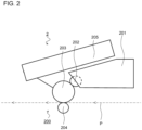
- the electrophotographic method can be implemented, for example, using the laser printer (electrophotographic method) depicted in FIG. 2 .
- the laser printer 2 depicted in FIG. 2 is equipped with an image forming unit 200.
- the image forming unit 200 is equipped with a process cartridge 201 that transfers resin powder to the surface of the object to be subjected to image forming P that has been transported, and an exposure unit 205 that exposes the surface of the developing photoreceptor drum 203 of the process cartridge 201.
- the process cartridge 201 has a developing roller 202, a developing photoreceptor drum 203, a transfer roller 204, and the like.
- the exposure unit 205 is equipped with a laser diode, polygon mirror, lens, reflector, and the like, and exposes the surface of the developing photoreceptor drum 203 by directing a laser beam toward the developing photoreceptor drum 203 based on image data input to the laser printer 2.
- the developing photoreceptor drum 203 is positioned adjacent to the developing roller 202.
- the surface of the developing photoreceptor drum 203 is uniformly and positively charged by a charger, not illustrated, and then exposed by the exposure unit 205.
- the exposed portion of the developing photoreceptor drum 203 has a lower potential than the other portions, and an electrostatic latent image based on the image data is formed on the developing photoreceptor drum 203.
- the electrostatic latent image is developed into a developed image by supplying a positively charged resin powder from the developing roller 202 to the surface of the developing photoreceptor drum 203 on which the electrostatic latent image is formed.
- the transfer roller 204 is positioned opposite the developing photoreceptor drum 203, and a negative transfer bias is applied by bias applying means not illustrated. With the transfer bias applied to the surface of the transfer roller 204, the developing image (resin powder) formed on the surface of the developing photoreceptor drum 203 is transferred to the surface of the object to be subjected to image forming P by sandwiching and transporting the object to be subjected to image forming P between the developing photoreceptor drum 203 on which the developing image (resin powder) is formed and the transfer roller 204 (transfer position).
- the resin powder may be, for example, a charged resin powder, as described above.
- the region where the charged resin powder is applied may be slightly larger than the region where the water-based ink is applied. Slightly larger means, for example, 0.5% or more, preferably 1% or more, and more preferably 2% or more.
- the resin powder applying step does not use an electrophotographic method, for example, the resin powder does not necessarily contain the charge control agent and the release agent.
- Thermal fixing in the thermal fixing step may be performed, for example, through contact with, or non-contact with, the object to be subjected to image forming.
- Examples of the contact method include methods that use heat rollers, commercially available hot presses, and the like.
- Examples of the non-contact method include methods that use ovens, belt conveyor ovens, dryers, and the like.
- the temperature of the heating member used in the thermal fixing is 100°C to 200°C, preferably 100°C to 150°C, and more preferably 110°C to 130°C.
- the thermal fixing step may be performed in a non-contact manner, and the thermal fixing step may be performed after the image forming step, followed by the resin powder applying step, followed by the thermal fixing step.
- the resin powder applying step is performed by the electrophotographic method, non-contact thermal fixing of the region where the water-based ink is applied before the resin powder applying step can prevent contamination of the roller that applies the resin powder.
- the inkjet recording device 1 in FIG.1 also includes a heat treating unit, not illustrated.
- the heat treating unit may include, inside thereof, a contact heating member or a non-contact heating member.
- Examples of the contact heating member include heat rollers, hot plates, and the like.
- Examples of the non-contact heating member include ovens, belt conveyor ovens, dryers, and the like.
- the heat treating unit may be provided independent of the inkjet recording device 1.
- the method for manufacturing the image formation according to the present invention includes the image forming step, and the image forming step is implemented by the image forming method according to the present invention.
- the image forming system according to the present invention includes an ink flow path, a resin powder housing section, ink applying means, and resin powder applying means, uses the ink applying means to apply water-based ink provided to the ink flow path to an object to be subjected to image forming, uses the resin powder applying means to apply the resin powder housed in the resin powder housing section to the object to be subjected to image forming so as to overlap an area to which the water-based ink was applied, and then supplies the water-based ink described in the above embodiment into the ink flow path.
- the image forming system according to the present invention may be a combination of the inkjet recording device 1 in FIG. 1 and the laser printer 2 according to FIG. 2 .
- the image forming system according to the present invention may be provided integrated with, or independent of, the inkjet recording device 1 and the laser printer 2.
- a mixture was obtained by adding pure water to 20 wt% of a pigment (carbon black) and 7 wt% (acid value: 175 mg KOH/g, molecular weight: 10000) of a styrene-acrylic acid copolymer neutralized with sodium hydroxide, for a total of 100 wt%, and then stirring and mixing.
- This mixture was put in a wet sand mill filled with 0.3 mm diameter zirconia beads, and dispersed for 6 hours. Then, the zirconia beads were removed using a separator, and the resin dispersion Bk shown in Table 1 was obtained by filtering with an acetate filter with a pore size of 3.0 ⁇ m.
- styrene-acrylic acid copolymers are water soluble polymers commonly used as dispersions for pigments.
- a mixture was obtained by adding pure water to 20 mass% of a pigment (C.I. pigment red 122) and 7 mass% (acid value: 50 mg KOH/g, molecular weight: 10000) of a styrene-acrylic acid copolymer neutralized with sodium hydroxide, for a total of 100 wt%, and then stirring and mixing.
- This mixture was put in a wet sand mill filled with 0.3 mm diameter zirconia beads, and dispersed for 6 hours. Then, the zirconia beads were removed using a separator, and the resin dispersion M shown in Table 1 was obtained by filtering with an acetate filter with a pore size of 3.0 ⁇ m.
- styrene-acrylic acid copolymers are water soluble polymers commonly used as dispersing agents for pigments.
- a substance synthesized by causing glycols and polyisocyanates to react was used.
- the average particle size of this fixing resin, as measured using a dynamic light scattering particle size distribution analyzer ("LB-550" manufactured by Horiba, Ltd.) was 40 nm.
- An ink solvent was obtained by uniformly mixing ingredients excluding a pigment in the water-based ink composition in Tables 1. Next, pigment was added to the ink solvent and mixed uniformly. Then, the water-based ink of Examples 1 through 15 shown in Table 1 and Comparative Examples 1 through 3 were obtained by filtering the resulting mixture with a cellulose acetate type membrane filter (pore size: 3.00 ⁇ m) manufactured by Toyo Roshi Kaisha, Ltd.
- the fixing agent, wetting agent, and surfactant in the OC ink compositions in Table 1 were mixed uniformly. Then, the water-based ink (OC ink) of Comparative Example 3 shown in Table 1 was obtained by filtering the resulting mixture with a cellulose acetate type membrane filter (pore size: 3.00 ⁇ m) manufactured by Toyo Roshi Kaisha, Ltd.
- a charge control resin liquid was obtained by mixing and stirring 82.5 parts of MEK (methyl ethyl ketone) and 17.5 parts of a charge control resin (product name: "FCA-201PS” manufactured by Fujikura Kasei Co., Ltd.) to dissolve the charge control resin in the MEK.
- a charge control resin emulsion was obtained by mixing 100 parts of distilled water with 100 parts of this charge control resin liquid and then stirring for 20 minutes at a rotation speed of 16000 rpm (tip peripheral speed: 10.5 m/s) using a homogenizer (rotor stator-type, shaft 18F, rotor diameter 12.5 mm: model DIAX-900 manufactured by Heidolph).
- a charge control resin fine particle suspension with charge control resin fine particles dispersed therein was obtained by transferring the charge control resin emulsion to a 1L separable flask, heating and stirring at 60°C for 120 minutes while blowing nitrogen into the gas phase to volatilize and remove MEK.
- the solid content concentration of the charge control resin fine particle suspension was 22.9%.
- the volume average particle size (median diameter: D50) of the charge control resin fine particles in the charge control resin fine particle suspension was 110 nm.
- a binder resin liquid was obtained by mixing 180 parts of a polyester resin (FC1565: Tg 62°C, Mn (number average molecular weight): 3600, Mw (weight average molecular weight): 50000, gel portion: less than 2 wt%, acid value: 6.0 KOH mg/g manufactured by Mitsubishi Rayon) with 720 parts of MEK, stirring, and then heating and stirring to a liquid temperature of 70°C.
- a polyester resin FC1565: Tg 62°C, Mn (number average molecular weight): 3600, Mw (weight average molecular weight): 50000, gel portion: less than 2 wt%, acid value: 6.0 KOH mg/g manufactured by Mitsubishi Rayon
- a binder resin emulsion was obtained by mixing 900 parts of the obtained binder resin liquid, 900 parts of distilled water, and 9.0 parts of 1N aqueous sodium hydroxide solution, and then stirring and emulsifying for 20 minutes at a rotation speed of 15000 rpm (tip peripheral speed: 13.0 m/s) using a homogenizer (shaft 22F, rotor diameter: 16.5 mm).
- a parent fine particle suspension with parent fine particles dispersed therein was obtained by transferring the emulsion to a 2L separable flask, and heating and stirring at 75°C for 140 minutes while blowing nitrogen into the gas phase to remove MEK.
- the solid content of the parent fine particle suspension was 23.1 mass%.
- the volume average particle size (median diameter: D50) of the parent fine particles in the parent fine particle suspension was 299 nm.
- the glass transition point (Tg) of the parent fine particles in the parent fine particle suspension was 58.3°C.
- a diluted parent fine particle suspension with a solid content concentration of 10% was prepared by mixing 57.6 parts of a 5% aqueous solution of nonionic surfactant (EPAN 785: polyoxyethylene polyoxypropylene block copolymer manufactured by DKS Co., Ltd.) with 692.6 parts of a parent fine particle suspension, and then diluting with 849.8 parts of distilled water. 35 parts of a 0.2N aluminum chloride aqueous solution were added to this diluted solution as a flocculant, then mixed at high speed for 10 minutes at a rotation speed of 8000 rpm using a homogenizer (shaft 22F, roller diameter: 16.5 mm).
- EPAN 785 polyoxyethylene polyoxypropylene block copolymer manufactured by DKS Co., Ltd.
- parent fine particles were aggregated by heating the diluted solution to 45°C while stirring at a rotation speed of 300 rpm with 6 flat turbine blades ( ⁇ 75 mm). Then, a resin powder parent particle suspension was obtained by adding 46 parts of a 0.2N sodium hydroxide solution as an aggregation terminator, heating to 90°C, and then stirring for approximately 6.5 hours. After filtering the obtained resin powder parent particle suspension, the filtered resin powder parent particles were washed with distilled water and put into a separable flask. 1600 parts of a resin powder parent particle suspension with a solid content of 10 mass% (160 parts as resin powder parent particles) were obtained by pouring distilled water into the particles to once again disperse the resin powder parent particles. The volume-based average particle size (Dv) of the resin powder parent particles was 8.1 ⁇ m.
- Resin powder creation step (1) Imparting charge to resin powder parent particles
- a mixture was prepared by mixing 7 parts of a charge control resin fine particle suspension with charge control resin fine particles dispersed therein (solid content: 22.9 mass%) (1.6 parts as charge control fine particles) with the 1600 parts of a resin powder parent particle suspension with a solid content of 10 mass% (160 parts as resin powder parent particles) in a 25°C water bath and stirring for 15 minutes at 200 rpm using an impeller (6-plate turbine two-stage blades: diameter 75 mm). Then, the mixture was filtered and a cake was washed with distilled water and filtered; this was repeated until the conductivity of the resulting filtrate became 4 ⁇ S/cm or less.
- HVK2150 hydrophobic silica manufactured by Clariant AG
- 1 part of NA50H hydrophobic silica manufactured by Aerosil Co., Ltd.
- MECHANOMILL manufactured by Okada Seiko Co., Ltd.
- Binder resin 80 to 90 wt% Release agent: 3 to 10 wt% Charge control agent: 0 to 5 wt% External additive: 1 to 2 wt%
- Example 8 thermal fixing was not performed after the water-based ink was applied, but rather only after the resin powder was applied.
- a resin powder was not used.
- Comparative Example 2 neither a water-soluble resin nor a resin emulsion was used.
- Comparative Example 3 a resin powder was not used and an OC ink was used.
- the resin powder was applied by hand according to the following procedures instead of using a laser printer. First, the required amount of the resin powder was spread on a suitable resin film. This was applied onto fabric on which the water-based ink had been applied, and then the resin film was peeled off to transfer the resin powder to the fabric, and then thermal fixing was performed.
- Solid printing was performed by ejecting water-based ink using an inkjet method. Visual evaluation was performed according to the following evaluation criteria.
- Color migration to a white test cloth was evaluated according to the following evaluation criteria by setting the white test cloth in the probe of an "RT-200" JSPS-type friction tester manufactured by Daiei Kagaku Seiki Mfg. Co., Ltd., and rubbing an image forming (ink film) portion thereupon.
- Abrasion resistance evaluation Evaluation criteria A: Absent B: Slightly present C: Present
- the recorded portion was rubbed reciprocally 10 times with a finger to see if fabric fluffing occurred.
- Examples 1 to 15 had favorable results for both the bleeding evaluation and the abrasion resistance evaluation.
- the abrasion resistance evaluation was superior in Examples 1 to 3, 5 to 8, and 10 to 13, where the region where the water-based ink (A) and resin powder (B) were applied was such that A ⁇ B.
- Comparative Examples 1-3 had inferior bleeding and abrasion resistance evaluation results. Specifically, Comparative Example 1, where resin powder was not applied, had an inferior abrasion resistance evaluation result. Comparative Example 2, in which the water-based ink did not contain a water-soluble resin or resin emulsion, demonstrated inferior abrasion resistance results. Comparative Example 3, which used an OC ink instead of the resin powder, had a poor bleeding evaluation results.
- An image forming method including: an image forming step of applying water-based ink to an object to be subjected to image forming by an inkjet method; a resin powder applying step of applying a resin powder to a region where the water-based ink has been applied (a first region); and a thermal fixing step of applying heat to the region where the water-based ink has been applied and a region where the resin powder has been applied (a second region), to thermally fix the water-based ink and the resin powder to the object, wherein the water-based ink contains a pigment and at least one of a water-soluble resin and a resin emulsion.
- Appendix 2 The image forming method according to Appendix 1 wherein a ratio (X/Y) of an applied amount (X) of the water-based ink and an applied amount (Y) of the resin powder is 0.04 or more and 240 or less.
- Appendix 3 The image forming method according to Appendix 1 or 2, wherein the water-soluble resin and the resin emulsion are one of urethane resin, polyester resin, and acrylic resin.
- Appendix 4 The image forming method according to any one of Appendices 1 to 3, wherein the solid content of the water-soluble resin or the resin emulsion relative to the total amount of the water-based ink is 5 mass% or more and 10 mass% or less.
- Appendix 5 The image forming method according to any one of Appendices 1 through 4 wherein an applied amount of the resin powder is 0.1 mg/cm 2 or more.
- Appendix 6 The image forming method according to any one of Appendices 1 to 5, wherein the resin powder contains a thermoplastic resin.
- Appendix 7) The image forming method according to any one of Appendices 1 to 6, wherein the resin powder is a charged resin powder.
- Appendix 8 The image forming method according to Appendix 7, wherein the resin powder applying step is performed by an electrophotographic method, in the resin powder applying process, the region where the charged resin powder is applied (the second region) is 1% or more larger than the region where the water-based ink is applied (the first region), the thermal fixing step is performed by a non-contact method, and the thermal fixing step is performed after the image forming step, then the resin powder applying step is performed, and then the thermal fixing step is performed.
- Appendix 9 A method for manufacturing an image-formed article that includes an image forming step, wherein the image forming step is implemented using the image forming method according to any one of Appendices 1 through 8.
- An image forming system comprising: an ink flow path, a resin powder housing section (a resin powder reservoir), ink applying means, and resin powder applying means, wherein the ink applying means is used to apply the water-based ink that was provided to the ink flow path to an object to be subjected to image forming, the resin powder applying means is used to apply the resin powder housed in the resin powder housing section to the object to be subjected to image forming so that the resin powder overlaps a region where the water-based ink was applied (the first region), and the water-based ink described in any one of Appendices 1 to 4 is supplied to the ink flow path.
- the image forming method according to the present invention is broadly applicable to forming images on various types of objects to be subjected to image forming.
Landscapes
- Chemical & Material Sciences (AREA)
- Wood Science & Technology (AREA)
- Materials Engineering (AREA)
- Organic Chemistry (AREA)
- Engineering & Computer Science (AREA)
- Life Sciences & Earth Sciences (AREA)
- Health & Medical Sciences (AREA)
- Toxicology (AREA)
- General Health & Medical Sciences (AREA)
- Physics & Mathematics (AREA)
- Thermal Sciences (AREA)
- Inks, Pencil-Leads, Or Crayons (AREA)
- Developing Agents For Electrophotography (AREA)
- Coloring (AREA)
- Ink Jet Recording Methods And Recording Media Thereof (AREA)
Abstract
Description
- The present invention relates to an image forming method, image-formed article manufacturing method, and image forming system.
- Conventionally, an image forming method is known in which an overcoat solution is dispensed onto a printed surface of print matter to form a film in order to enhance the abrasion resistance of the printed matter (Patent Document 1).
- Patent Document 1:
Japanese Unexamined Patent Application Publication No. 2003-053942 - However, the image forming method using a liquid overcoat agent as described above has a problem with bleeding occurring in the formed image. In addition, the liquid overcoat agent spreads wet on the image surface, and thus does not provide sufficient abrasion resistance.
- Thus, an object of the present invention is to provide an image forming method, image-formed article manufacturing method, and image forming system, without bleeding and with excellent abrasion resistance.
- In order to achieve the aforementioned object, the image forming method of the present invention includes an image forming step of applying water-based ink to an object to be subjected to image forming by an inkjet method, a resin powder applying step of applying a resin powder to a region where the water-based ink has been applied, and a thermal fixing step of applying heat to the region where the water-based ink has been applied and a region where the resin powder has been applied, to thermally fix the water-based ink and the resin powder to the object, wherein the water-based ink contains a pigment, and at least one of a water-soluble resin and a resin emulsion.
- The image forming method, method of manufacturing an image-formed article, and image forming system of the present invention can form images that are free from bleeding and have excellent abrasion resistance.
-
-
FIG. 1 is a schematic perspective view depicting an example of an inkjet recording device in an image forming system according to the present invention. -
FIG. 2 is a schematic view depicting an example of a laser printer (electrophotographic method) in an image forming system according to the present invention. - In the present invention, "mass" may be read as "weight" unless otherwise specified. For example, unless otherwise specified, "mass ratio" may be read as "weight ratio" and "mass %" may be read as "weight %."
- The image forming method of the present invention is described below. The image forming method according to the present invention includes a resin powder applying step that applies a resin powder to an object to be subjected to image forming; an image forming step that uses an inkjet method to apply a water-based ink to an area in which the resin powder was applied; and a thermal fixing step that applies heat to the area in which the resin powder was applied and the area in which the water-based ink was applied to fix the resin powder and the water-based ink to the object wherein the water-based ink contains a pigment and at least one of a water-soluble resin and a resin emulsion.
- In the present invention, "pigment" includes, at least, either a "resin dispersed pigment" or a "self-dispersing pigment" unless otherwise specified. The resin dispersed pigment is, for example, a pigment in which a pigment particle can be dispersed in a solvent by a resin dispersing agent. Additionally, the self-dispersing pigment is one in which pigment particles can be dispersed in a solvent without using a resin dispersing agent.
- Examples of the resin dispersed pigment include carbon black, inorganic pigments, organic pigments, and the like. Examples of the above carbon black include furnace black, lamp black, acetylene black, channel black, and the like. Examples of the above inorganic pigments include titanium oxide, iron oxide-based inorganic pigments, carbon black-based inorganic pigments, and the like. Examples of the above organic pigments include azo pigments such as azo lakes, insoluble azo pigments, condensed azo pigments, and chelate azo pigments, and the like; polycyclic pigments such as phthalocyanine pigments, perylene and perinone pigments, anthraquinone pigments, quinacridone pigments, dioxazine pigments, thioindigo pigments, isoindolinone pigments, quinophthalone pigments, and the like; dye lake pigments such as basic dye lake pigments, acid dye lake pigments, and the like; nitro pigments; nitroso pigments; and aniline black daylight fluorescent pigments, and the like. Any other pigment that is dispersible in the aqueous phase may also be used. Specific examples of these pigments include C. I. Pigment Black 1, 6 and 7; C. I. Pigment Yellow 1, 2, 3, 12, 13, 14, 15, 16, 17, 55, 74, 78, 150, 151, 154, 180, 185, and 194; C.I. pigment orange 31 and 43; C.I. pigment red 2, 3, 5, 6, 7, 12, 15, 16, 48, 48:1, 53:1, 57, 57:1, 112, 122, 123, 139, 144, 146, 149, 150, 166, 168, 175, 176, 177, 178, 184, 185, 190, 202, 209, 221, 222, 224, and 238; C.I. pigment violet 19 and 196; C.I. pigment blue 1, 2, 3, 15, 15:1, 15:2, 15:3, 15:4, 16, 22, and 60; C.I. pigment green 7 and 36; as well as solid solutions of these pigments, and the like.
- For example, a general polymer dispersing agent (also referred to as a pigment dispersing resin, a resign dispersing agent, or the like) may be used as the resin dispersing agent, or the agent may be prepared in-house. Furthermore, the pigment may be one that is encapsulated by a polymer in the water-based ink according to the present invention. For example, an agent containing at least a methacrylic acid or an acrylic acid as a monomer, for example, a commercially available agent, may be used as the resin dispersing agent. For example, the resin dispersing agent may be a hydrophobic monomer such as styrene, a styrene derivative, vinylnaphthalene, a vinylnaphthalene derivative, an aliphatic alcohol ester of α,β-ethylenically unsaturated carboxylic acid, and the like; or a block copolymer, a graft copolymer, or a random copolymer consisting of two or more monomers selected from a group consisting of acrylic acid, acrylic acid derivatives, maleic acid, maleic acid derivatives, itaconic acid, itaconic acid derivatives, fumaric acid, and fumaric acid derivatives; or salts of these, and the like. Examples of the above commercially available agent include "Joncryl® 611," "Joncryl® 60," "Joncryl® 586," "Joncryl® 687," "Joncryl® 63," and "Joncryl® HPD296"manufactured by Johnson Polymers, Co., Ltd.; "Disperbyk 190" and "Disperbyk 191" manufactured by BYK Chemie Co., Ltd.; and "Solsperse 20000" and "Solsperse 27000" manufactured by Zeneca Co., Ltd., and the like.
- Examples of methods for dispersing the pigment using the pigment dispersing resin include dispersing the pigment using a dispersing device. The dispersing device used to disperse the pigment may be any general dispersing machine, and examples include a ball mill, a roll mill, a sand mill (for example, a high speed model), or the like.
- The self-dispersing type pigment is a pigment that is made dispersible in water without the use of dispersants by introducing, for example, at least one type of hydrophilic functional group such as a carbonyl group, hydroxyl group, carboxylic acid group, sulfonic acid group, phosphoric acid group, and the like, and salts of these, in pigment particles through chemical bonding, either directly or through another group. A pigment processed using the method disclosed in, for example,
Japanese Unexamined Patent Application Publication No. H08-3498 2000-513396 2008-524400 2009-515007 2011-515535 - A pigment solid content of the pigment in the total amount of the water-based ink is, for example, 0.5 mass% to 20 mass%, preferably 1 mass% to 10 mass%, and more preferably 3 mass% to 5 mass%.
- The aqueous ink contains at least one of a water-soluble resin and a resin emulsion.
- Examples of the water-soluble resin include resins having structures with relatively high hydrophilic contents and that are soluble in water. Examples of the water-soluble resin include urethane resins, polyester resins, acrylic resins, alkyd resins, styrene-maleic acid copolymers, cellulose derivatives, polyvinylpyrrolidone, polyvinyl alcohol, and the like. Either one type of these water-soluble resins may be used alone, or two or more types thereof may be used together. The water-soluble resin is preferably a urethane resin, polyester resin, or acrylic resin, for example.
- The resin emulsion is, for example, configured of fine resin particles and a dispersing medium (for example, water), and the fine resin particles are not dissolved in the dispersing medium, but dispersed with a specific particle size. The aforementioned resin emulsion includes, for example, acrylic resins, urethane resins, polyester resins, polystyrene resins, polyethylene resins, vinyl chloride resins, and the like. Either one type of these resin emulsions may be used alone, or two or more types thereof may be used together. Preferred examples of the water-based resin emulsion include urethane resins, polyester resins, acrylic resins, and the like.
- The resin emulsion may be, for example, a commercially available one. Examples of those that are commercially available include the polycarbonate urethane resin emulsions "SuperFlex® 460" manufactured by DKS Co., Ltd., "TAKELAC® W-6110" manufactured by Mitsui Chemicals Co., Ltd., and "HYDRAN® WLS-210" manufactured by DIC Co., Ltd., and the like; the polyester urethane resin emulsions "UCOAT® UWS-145" manufactured by Sanyo Chemical Industries, Ltd., "TAKELAC® W-5030" manufactured by Mitsui Chemicals Co., Ltd., and "HYDRAN® HW-920" manufactured by DIC Co., Ltd., and the like; and the polyether urethane resin emulsions "TAKELAC® W-6061T" manufactured by Mitsui Chemicals Co., Ltd., and "HYDRAN® FCS-855" and "HYDRAN® WLS-201" manufactured by DIC Co., Ltd., and the like.
- A solid content of the resin emulsion in the total amount of the water-based ink is, for example, 1 mass% to 20 mass%, preferably 5 mass% to 10 mass%, and more preferably 7 mass% to 10 mass%.
- The water-based ink may also contain water, a surfactant, wetting agent, penetrant, pH adjusting agent, viscosity modifying agent, surface tension modifying agent, antifungal agent, cross-linking agent, and the like.
- It is preferable that the water be deionized water or pure water. The amount of the water contained in the total amount of the water-based ink is, for example, 10 mass% to 90 mass%, and preferably 20 mass% to 80 mass%. An amount of contained water may be, for example, the balance of other components.
- Examples of the surfactant include nonionic surfactants. The nonionic surfactant may also be, for example, a commercially available product. Examples of commercially available products include "OLFINE® E1004," "OLFINE® E1006," and "OLFINE® E1010" manufactured by Nissin Chemical Co., Ltd., and the like.
- An amount of the nonionic surfactant contained in the total amount of the water-based ink is, for example, 0.1 mass% to 2 mass%, preferably 0.3 mass% to 1.5 mass%, and more preferably 0.5 mass% to 1 mass%.
- The surfactant may also contain surfactants other than nonionic surfactants (for example, anionic surfactants, cationic surfactants, amphoteric surfactants, and the like), however, a nonionic surfactant alone may be used as the surfactant.
- Examples of the wetting agent include lower alcohols such as methyl alcohol, ethyl alcohol, n-propyl alcohol, isopropyl alcohol, n-butyl alcohol, sec-butyl alcohol, tert-butyl alcohol, and the like; amides such as dimethylformamide, dimethylacetamide, and the like; ketones such as acetone, and the like; ketoalcohols such as diacetone alcohol, and the like; ethers such as tetrahydrofuran, dioxane, and the like; polyethers such as polyalkylene glycol, and the like; polyhydric alcohols such as alkylene glycol, glycerin, trimethylolpropane, trimethylolethane, and the like; 2-pyrrolidone; N-methyl-2-pyrrolidone; 1,3-dimethyl-2-imidazolidinone; and the like. Examples of the polyalkylene glycol include polyethylene glycol, polypropylene glycol, and the like. Examples of the alkylene glycol include ethylene glycol, propylene glycol, butylene glycol, diethylene glycol, triethylene glycol, dipropylene glycol, tripropylene glycol, thiodiglycol, hexylene glycol, and the like. Either one type of these wetting agents may be used alone, or two or more types thereof may be used together. Among these, polyhydric alcohols such as alkylene glycol, glycerin, and the like, are preferred.
- An amount of the wetting agent contained in the total amount of the water-based ink is, for example, 1 mass% to 30 mass%, preferably 5 mass% to 20 mass%, and more preferably 10 mass% to 15 mass%.
- Examples of the penetrant include glycol ether compounds and alkylene diols. Examples of the glycol ether compounds include ethylene glycol methyl ether, ethylene glycol ethyl ether, ethylene glycol-n-propyl ether, diethylene glycol methyl ether, diethylene glycol ethyl ether, diethylene glycol-n-propyl ether, diethylene glycol-n-butyl ether, diethylene glycol-n-hexyl ether, triethylene glycol methyl ether, triethylene glycol ethyl ether, triethylene glycol-n-propyl ether, triethylene glycol-n-butyl ether, propylene glycol methyl ether, propylene glycol ethyl ether, propylene glycol-n-propyl ether, propylene glycol-n-butyl ether, dipropylene glycol methyl ether, dipropylene glycol ethyl ether, dipropylene glycol-n-propyl ether, dipropylene glycol-n-butyl ether, tripropylene glycol methyl ether, tripropylene glycol ethyl ether, tripropylene glycol-n-propyl ether, tripropylene glycol-n-butyl ether, and the like. Examples of alkylene diols include 1,2-hexanediol, 1,2-heptanediol, 1,3-propanediol, 1,2-butanediol, 1,3-butanediol, 1,4-butanediol, 2,3-butanediol, 3-methyl-1,3-butanediol, 1,3-propanediol, 1,2-butanediol, 1,2-pentanediol, 1,4-butanediol, 1,5-pentanediol, 1,6-hexane diol, 2-methyl-2,4-pentanediol, 3-methyl-1,5-pentanediol, and the like. Either one type of these penetrants may be used alone, or two or more types thereof may be used together.
- The amount of the penetrant contained in the total amount of the water-based ink is, for example, 0 mass% to 20 mass%, preferably 0 mass% to 15 mass%, and more preferably 1 mass% to 6 mass%.
- In the present invention, "resin powder" refers to a powder containing resin as a main component. The resin powder may contain, for example, components such as a binder resin, a release agent, a charge control agent, an external additive, and the like. Note that there are substances containing binder resins, release agents, charge control agents, external additives, pigments, and the like, that are used as toners for printing, and that resin powder may be obtained by removing the pigments from such toners.
- The binder resin may be, for example, a thermoplastic resin. The thermoplastic resin is not particularly limited, and examples include polyester resins, and the like. The polyester resin may have an acid value of, for example, 0.5 to 40 mg KOH/g, and preferably 1.0 to 20 mg KOH/g. Furthermore, a weight average molecular weight (according to GPC measurement using standard polystyrene as a calibration curve) thereof may be, for example, 9,000 to 200,000, and preferably 20,000 to 150,000. Additionally, a gel portion (THF insoluble matter) thereof may be, for example, 10 mass% or less, and preferably 0.5 to 10 mass%. Moreover, a glass transition point (Tg) thereof may be, for example, 50 to 70°C, and preferably 55 to 65°C. Specific examples of commercially available polyester resins include FC1565 (manufactured by Mitsubishi Rayon), FC023 (manufactured by Mitsubishi Rayon), and the like. The water-based ink used in the image forming method of the present invention contains at least one of water soluble resins and resin emulsions, as described above. These are added in consideration of fixability to the aforementioned object to be subjected to image forming, but heating (thermal fixing) is required for fixing. If, for example, a thermosetting resin is used as the binder resin, the thermosetting resin will not melt, so an overcoat cannot be applied. Therefore, it is preferable to include the aforementioned thermoplastic resin that melts during thermal fixing as the binder resin.
- Examples of the release agent include polyolefin wax, long-chain hydrocarbon wax, and ester wax.
- The charge control agent provides chargeability to the resin powder. The aforementioned chargeability may be either positive or negative. Examples of the charge control agent include nigrosine dyes, triphenylmethane dyes, chromium-containing metal complex dyes, molybdate chelate pigments, rhodamine dyes, alkoxy amines, quaternary ammonium salts (including fluorine modified quaternary ammonium salts), alkyl amides, phosphorus alone or in compounds, tungsten alone or in compounds, fluorinated activators, metal salts of salicylic acid, metal salts of salicylic acid derivatives, and the like. Copper phthalocyanine, perylene, quinacridone, azo pigments, and the like are also possible. Furthermore, polymeric compounds having functional groups such as sulfonate groups, carboxylate groups, quaternary ammonium salts, and the like can also be suggested.
- The added ratio of the charge control agent is, for example, 0.1 mass part or more, preferably 1 mass part or more, and for example 20 mass parts or less, preferably 10 mass parts or less, with regard to 100 mass parts of binding resin.
- The external additive adjusts the chargeability, flowability, and storage stability of the resin powder. The external additive includes, for example, inorganic particles, synthetic resin particles, and the like.
- Examples of the inorganic particles include silica, aluminum oxide, titanium oxide, silicon aluminum co-oxide, silicon titanium co-oxide, and hydrophobically treated products thereof. The hydrophobically treated silica can be obtained, for example, by treating silica fine powder with silicone oil or a silane coupling agent such as dichlorodimethylsilane, hexamethyldisilazane, tetramethyldisilazane, and the like.
- Examples of the synthetic resin particles include methacrylic ester polymer particles, acrylic ester polymer particles, styrene-methacrylic ester copolymer particles, styrene-acrylic ester copolymer particles, and core-shell particles in which the core is a styrene polymer and the shell is a methacrylic ester polymer.
- The particle size of the external additive is smaller than the particle size of the binder resin. The particle size of the external additive is, for example, 2 µm or less, preferably 0.1 µm or less, and even more preferably 0.03 µm or less.
- The added ratio of the external additive is, for example, 0.1 mass parts or more and for example 10 mass parts or less, to 100 mass parts of the binder resin.
- Alower limit of the amount of the water-based ink applied is, for example, 0.004 mg/cm2 or more, 0.04 mg/cm2 or more, or 0.4 mg/cm2 or more. An upper limit of the amount of the water-based ink applied is, for example, 24 mg/cm2 or less, 12 mg/cm2 or less, 8 mg/cm2 or less, or 4 mg/cm2 or less. Note that the upper limit of the applied amount of the water-based ink is preferably 4 mg/cm2 or less, from the viewpoint of bleeding of the water-based ink.
- A lower limit of the amount of the resin powder applied is, for example, 0.1 mg/cm2 or more. The upper limit of the amount of the resin powder applied is, for example, 1.2 mg/cm2 or less. The present inventors have found that a sufficient OD value cannot be obtained when the amount of the resin powder applied is less than 0.1 mg/cm2. Furthermore, from the viewpoint of controlling amounts consumed, the smaller the amount of the resin powder applied, the better. For these reasons, it is preferable that the amount of the resin powder applied be 0.1 mg/cm2 or more.
- The ratio (X/Y) between the amount (X) of applied water-based ink and the amount (Y) of applied resin powder is, for example, 0.04 to 240, preferably 0.04 to 80, more preferably 0.4 to 80, and even more preferably 40 to 80.
- Examples of the object to be subjected to image forming include recording media such as fabric, paper, or the like.
- The fabric may include both knitted and woven fabrics. Examples of the material of the fabric include natural fibers and synthetic fibers. Examples of the natural fibers include cotton, silk, and the like. The material of the fabric may be, for example, a blend spun by mixing a plurality of types of the natural fibers, or a blend spun by mixing the natural fibers and the synthetic fibers. Examples of the synthetic fibers include polyester, acrylic, rayon, urethane, nylon, and the like. Examples of a blend of the natural fibers and the synthetic fibers include a 50%/50% blend of cotton and polyester, and the like.
- Examples of the recording medium include plain paper, glossy paper, matte paper, coated paper, synthetic paper, paperboard, cardboard, film, and the like.
- The image forming step can be implemented using, for example, the inkjet recording device illustrated in
FIG. 1 . - A configuration of an example of the inkjet recording device is illustrated in
FIG. 1 . As illustrated in the figure, this inkjet recording device 1 includes anink cartridge 101, ink applying means (inkjet head) 102, ahead unit 103, acarriage 104, adrive unit 105, aplaten roller 106, and apurge device 107 as major constituent elements. Furthermore, although not illustrated in the figure, theink cartridge 101 and the ink applying means 102 are connected by an ink flow path. The water-based ink is supplied to the ink flow path from theink cartridge 101 in which the water-based ink is stored and the ink applying means 102 applies the water-based ink to the object to be subjected to image forming P. - The
ink cartridge 101 may contain, for example, the water-based ink. A conventionally known unit may be used as a main unit of the ink cartridge. - Additionally, although not illustrated in the figure, the inkjet recording device 1 includes, in addition to the
ink cartridge 101 containing the water-based ink, a set of four ink cartridges, each containing one of four colors of water-based ink; yellow, magenta, cyan, and black. An integrated ink cartridge, an interior of which is partitioned so as to form a water-based yellow ink storage reservoir, a water-based magenta ink storage reservoir, a water-based cyan ink storage reservoir, and a water-based black ink storage reservoir, may be used in place of the set of four ink cartridges. - The
inkjet head 102, which is installed in thehead unit 103, performs image forming on the object to be subjected to image forming P. Theink cartridge 101 and thehead unit 103 are mounted on thecarriage 104. Thedrive unit 105 moves thecarriage 104 reciprocally in a linear direction. A conventionally known unit (seeJapanese Unexamined Patent Application Publication No. 2008-246821 drive unit 105. Theplaten roller 106 is arranged extending in a reciprocating direction of thecarriage 104, and facing theinkjet head 102. - The
purge device 107 sucks up defective ink containing air bubbles, and the like, that accumulates inside theinkjet head 102. A conventionally known device (seeJapanese Unexamined Patent Application Publication No. 2008-246821 purge device 107. - A
wiper member 118 is arranged on theplaten roller 106 side of thepurge device 107 adjacent to thepurge device 107. Thewiper member 118 is formed in the shape of a spatula, and wipes a nozzle forming surface of theinkjet head 102 in conjunction with a movement of thecarriage 104. InFIG. 1 , acap 117 covers a plurality of nozzles on theinkjet head 102, which is returned to a set position when recording finishes to prevent ink from drying. - In the inkjet recording device 1 according to this example, the
ink cartridge 101 is mounted, together with thehead unit 103, in onecarriage 104. However, the present invention is not limited to this. In the inkjet recording device 1, theink cartridge 101 may be mounted on a different carriage than thehead unit 103. Furthermore, theink cartridge 101 may be arranged and fixed inside the inkjet recording device 1, and not mounted on thecarriage 104. In these embodiments, for example, theink cartridge 101 and thehead unit 103 mounted on thecarriage 104 are connected by the ink flow path, which is a tube, or the like, and the ink is supplied to thehead unit 103 from thecartridge 101. Furthermore, in these embodiments, a bottle shaped ink bottle may be used instead of theink cartridge 101. In this case, it is preferable that an injection port for injecting ink from the outside into an interior be provided in the ink bottle. - The image forming step using this inkjet recording device 1 is, for example, implemented as follows. First the object to be subjected to image forming P is supplied from a side of, or below, the inkjet recording device 1. The object to be subjected to image forming P is introduced between the
inkjet head 102 and theplaten roller 106. A specified image is formed of water-based ink applied from theinkjet head 102 to an area of the introduced object to be subjected to image forming P. The object to be subjected to image forming P is ejected from the inkjet recording device 1 after the image forming. Mechanisms for supplying and ejecting the object to be subjected to image forming P have been omitted inFIG. 1 and are thus not illustrated. - Although the device illustrated in
FIG. 1 uses a serial-type inkjet head, the present invention is not limited to this and thus, for example, the device may be one that uses a line-type inkjet head or a roll-to-roll. Note that the serial-type inkjet head is an inkjet head that prints while reciprocating the inkjet head in a width direction of an image forming object. A line-type inkjet head is an inkjet head that covers an entire width of the image forming object. Roll-to-roll is a method in which a roll-shaped image forming object is fed out, printed, and then wound back up into a roll shape. - The resin powder applying step may be performed manually or by an electrophotographic method. When performed manually, the resin powder can be applied to the region where water-based ink was applied using, for example, hands or instruments such as spoons, brushes, powder sieves, and the like. When performed using an electrophotographic method, the resin powder can be applied to the region where the water-based ink was applied using, for example, a conventionally known laser printer.
- The electrophotographic method can be implemented, for example, using the laser printer (electrophotographic method) depicted in
FIG. 2 . - The laser printer 2 depicted in
FIG. 2 is equipped with an image forming unit 200. The image forming unit 200 is equipped with aprocess cartridge 201 that transfers resin powder to the surface of the object to be subjected to image forming P that has been transported, and anexposure unit 205 that exposes the surface of the developingphotoreceptor drum 203 of theprocess cartridge 201. - The
process cartridge 201 has a developingroller 202, a developingphotoreceptor drum 203, atransfer roller 204, and the like. Theexposure unit 205 is equipped with a laser diode, polygon mirror, lens, reflector, and the like, and exposes the surface of the developingphotoreceptor drum 203 by directing a laser beam toward the developingphotoreceptor drum 203 based on image data input to the laser printer 2. - The developing
photoreceptor drum 203 is positioned adjacent to the developingroller 202. The surface of the developingphotoreceptor drum 203 is uniformly and positively charged by a charger, not illustrated, and then exposed by theexposure unit 205. The exposed portion of the developingphotoreceptor drum 203 has a lower potential than the other portions, and an electrostatic latent image based on the image data is formed on the developingphotoreceptor drum 203. Furthermore, the electrostatic latent image is developed into a developed image by supplying a positively charged resin powder from the developingroller 202 to the surface of the developingphotoreceptor drum 203 on which the electrostatic latent image is formed. - The
transfer roller 204 is positioned opposite the developingphotoreceptor drum 203, and a negative transfer bias is applied by bias applying means not illustrated. With the transfer bias applied to the surface of thetransfer roller 204, the developing image (resin powder) formed on the surface of the developingphotoreceptor drum 203 is transferred to the surface of the object to be subjected to image forming P by sandwiching and transporting the object to be subjected to image forming P between the developingphotoreceptor drum 203 on which the developing image (resin powder) is formed and the transfer roller 204 (transfer position). - The resin powder may be, for example, a charged resin powder, as described above. In the resin powder applying step, the region where the charged resin powder is applied may be slightly larger than the region where the water-based ink is applied. Slightly larger means, for example, 0.5% or more, preferably 1% or more, and more preferably 2% or more.
- If the resin powder applying step does not use an electrophotographic method, for example, the resin powder does not necessarily contain the charge control agent and the release agent.
- Thermal fixing in the thermal fixing step may be performed, for example, through contact with, or non-contact with, the object to be subjected to image forming. Examples of the contact method include methods that use heat rollers, commercially available hot presses, and the like. Examples of the non-contact method include methods that use ovens, belt conveyor ovens, dryers, and the like. The temperature of the heating member used in the thermal fixing is 100°C to 200°C, preferably 100°C to 150°C, and more preferably 110°C to 130°C.
- When the resin powder applying step is performed by the electrophotographic method, for example, the thermal fixing step may be performed in a non-contact manner, and the thermal fixing step may be performed after the image forming step, followed by the resin powder applying step, followed by the thermal fixing step. When the resin powder applying step is performed by the electrophotographic method, non-contact thermal fixing of the region where the water-based ink is applied before the resin powder applying step can prevent contamination of the roller that applies the resin powder.
- If the thermal fixing step is performed after the image forming step, the inkjet recording device 1 in
FIG.1 also includes a heat treating unit, not illustrated. The heat treating unit may include, inside thereof, a contact heating member or a non-contact heating member. Examples of the contact heating member include heat rollers, hot plates, and the like. Examples of the non-contact heating member include ovens, belt conveyor ovens, dryers, and the like. The heat treating unit may be provided independent of the inkjet recording device 1. - A method for manufacturing the image formation according to the present invention is described next. The method for manufacturing the image formation according to the present invention includes the image forming step, and the image forming step is implemented by the image forming method according to the present invention.
- An image forming system according to the present invention is described next. The image forming system according to the present invention includes an ink flow path, a resin powder housing section, ink applying means, and resin powder applying means, uses the ink applying means to apply water-based ink provided to the ink flow path to an object to be subjected to image forming, uses the resin powder applying means to apply the resin powder housed in the resin powder housing section to the object to be subjected to image forming so as to overlap an area to which the water-based ink was applied, and then supplies the water-based ink described in the above embodiment into the ink flow path.
- The image forming system according to the present invention may be a combination of the inkjet recording device 1 in
FIG. 1 and the laser printer 2 according toFIG. 2 . The image forming system according to the present invention may be provided integrated with, or independent of, the inkjet recording device 1 and the laser printer 2. - Examples according to the present invention are described next along with comparative examples. Note the present invention is neither limited nor restricted by the examples and comparative examples described below. Also, in the following description, "part" and "%" are based on mass unless otherwise specified. Furthermore, various types of physical properties were measured according to measurement methods described later.
- (Water-based ink) 1. Preparation of pigment dispersion <Self-dispersing Bk> 40 g of carbon black "#2650" manufactured by Mitsubishi Chemical Co., Ltd. was mixed with 200 g of deionized water and then pulverized in a bead mill. A carboxyl group agent was added to this, and the mixture was oxidized by heating and stirring. Then, the resulting liquid was washed several times with a solvent, poured into water, rewashed repeatedly in water, filtered with a filter, and the self-dispersing Bk pigment shown in Table 1 was obtained. The average particle size of the carbon black contained in this self-dispersing Bk pigment, as measured using an "LB-550" manufactured by Horiba, Ltd. was 135 nm.
- A mixture was obtained by adding pure water to 20 wt% of a pigment (carbon black) and 7 wt% (acid value: 175 mg KOH/g, molecular weight: 10000) of a styrene-acrylic acid copolymer neutralized with sodium hydroxide, for a total of 100 wt%, and then stirring and mixing. This mixture was put in a wet sand mill filled with 0.3 mm diameter zirconia beads, and dispersed for 6 hours. Then, the zirconia beads were removed using a separator, and the resin dispersion Bk shown in Table 1 was obtained by filtering with an acetate filter with a pore size of 3.0 µm. Note that styrene-acrylic acid copolymers are water soluble polymers commonly used as dispersions for pigments.
- A mixture was obtained by adding pure water to 20 mass% of a pigment (C.I. pigment red 122) and 7 mass% (acid value: 50 mg KOH/g, molecular weight: 10000) of a styrene-acrylic acid copolymer neutralized with sodium hydroxide, for a total of 100 wt%, and then stirring and mixing. This mixture was put in a wet sand mill filled with 0.3 mm diameter zirconia beads, and dispersed for 6 hours. Then, the zirconia beads were removed using a separator, and the resin dispersion M shown in Table 1 was obtained by filtering with an acetate filter with a pore size of 3.0 µm. Note that styrene-acrylic acid copolymers are water soluble polymers commonly used as dispersing agents for pigments.
- A substance synthesized by causing glycols and polyisocyanates to react was used. The average particle size of this fixing resin, as measured using a dynamic light scattering particle size distribution analyzer ("LB-550" manufactured by Horiba, Ltd.) was 40 nm.
- 44.7 wt% of Mowinyl 6899D (manufactured by Japan Coating Resin Co., Ltd.) was used.
- 30 wt% of elitel KT-8803 (manufactured by UNITIKA, Ltd.) was used.
- An ink solvent was obtained by uniformly mixing ingredients excluding a pigment in the water-based ink composition in Tables 1. Next, pigment was added to the ink solvent and mixed uniformly. Then, the water-based ink of Examples 1 through 15 shown in Table 1 and Comparative Examples 1 through 3 were obtained by filtering the resulting mixture with a cellulose acetate type membrane filter (pore size: 3.00 µm) manufactured by Toyo Roshi Kaisha, Ltd.
- The fixing agent, wetting agent, and surfactant in the OC ink compositions in Table 1 were mixed uniformly. Then, the water-based ink (OC ink) of Comparative Example 3 shown in Table 1 was obtained by filtering the resulting mixture with a cellulose acetate type membrane filter (pore size: 3.00 µm) manufactured by Toyo Roshi Kaisha, Ltd.
- A charge control resin liquid was obtained by mixing and stirring 82.5 parts of MEK (methyl ethyl ketone) and 17.5 parts of a charge control resin (product name: "FCA-201PS" manufactured by Fujikura Kasei Co., Ltd.) to dissolve the charge control resin in the MEK. A charge control resin emulsion was obtained by mixing 100 parts of distilled water with 100 parts of this charge control resin liquid and then stirring for 20 minutes at a rotation speed of 16000 rpm (tip peripheral speed: 10.5 m/s) using a homogenizer (rotor stator-type, shaft 18F, rotor diameter 12.5 mm: model DIAX-900 manufactured by Heidolph). A charge control resin fine particle suspension with charge control resin fine particles dispersed therein was obtained by transferring the charge control resin emulsion to a 1L separable flask, heating and stirring at 60°C for 120 minutes while blowing nitrogen into the gas phase to volatilize and remove MEK. The solid content concentration of the charge control resin fine particle suspension was 22.9%. Furthermore, the volume average particle size (median diameter: D50) of the charge control resin fine particles in the charge control resin fine particle suspension was 110 nm.
- A binder resin liquid was obtained by mixing 180 parts of a polyester resin (FC1565: Tg 62°C, Mn (number average molecular weight): 3600, Mw (weight average molecular weight): 50000, gel portion: less than 2 wt%, acid value: 6.0 KOH mg/g manufactured by Mitsubishi Rayon) with 720 parts of MEK, stirring, and then heating and stirring to a liquid temperature of 70°C.
- A binder resin emulsion was obtained by mixing 900 parts of the obtained binder resin liquid, 900 parts of distilled water, and 9.0 parts of 1N aqueous sodium hydroxide solution, and then stirring and emulsifying for 20 minutes at a rotation speed of 15000 rpm (tip peripheral speed: 13.0 m/s) using a homogenizer (shaft 22F, rotor diameter: 16.5 mm).
- A parent fine particle suspension with parent fine particles dispersed therein was obtained by transferring the emulsion to a 2L separable flask, and heating and stirring at 75°C for 140 minutes while blowing nitrogen into the gas phase to remove MEK. The solid content of the parent fine particle suspension was 23.1 mass%. Furthermore, the volume average particle size (median diameter: D50) of the parent fine particles in the parent fine particle suspension was 299 nm. Additionally, the glass transition point (Tg) of the parent fine particles in the parent fine particle suspension was 58.3°C.
- Next, 1600 parts of a diluted parent fine particle suspension with a solid content concentration of 10% was prepared by mixing 57.6 parts of a 5% aqueous solution of nonionic surfactant (EPAN 785: polyoxyethylene polyoxypropylene block copolymer manufactured by DKS Co., Ltd.) with 692.6 parts of a parent fine particle suspension, and then diluting with 849.8 parts of distilled water. 35 parts of a 0.2N aluminum chloride aqueous solution were added to this diluted solution as a flocculant, then mixed at high speed for 10 minutes at a rotation speed of 8000 rpm using a homogenizer (shaft 22F, roller diameter: 16.5 mm). Then, parent fine particles were aggregated by heating the diluted solution to 45°C while stirring at a rotation speed of 300 rpm with 6 flat turbine blades (ϕ75 mm). Then, a resin powder parent particle suspension was obtained by adding 46 parts of a 0.2N sodium hydroxide solution as an aggregation terminator, heating to 90°C, and then stirring for approximately 6.5 hours. After filtering the obtained resin powder parent particle suspension, the filtered resin powder parent particles were washed with distilled water and put into a separable flask. 1600 parts of a resin powder parent particle suspension with a solid content of 10 mass% (160 parts as resin powder parent particles) were obtained by pouring distilled water into the particles to once again disperse the resin powder parent particles. The volume-based average particle size (Dv) of the resin powder parent particles was 8.1 µm.
- A mixture was prepared by mixing 7 parts of a charge control resin fine particle suspension with charge control resin fine particles dispersed therein (solid content: 22.9 mass%) (1.6 parts as charge control fine particles) with the 1600 parts of a resin powder parent particle suspension with a solid content of 10 mass% (160 parts as resin powder parent particles) in a 25°C water bath and stirring for 15 minutes at 200 rpm using an impeller (6-plate turbine two-stage blades: diameter 75 mm). Then, the mixture was filtered and a cake was washed with distilled water and filtered; this was repeated until the conductivity of the resulting filtrate became 4 µS/cm or less.
- Next, 1 part of HVK2150 (hydrophobic silica manufactured by Clariant AG) and 1 part of NA50H (hydrophobic silica manufactured by Aerosil Co., Ltd.) were blended with 100 parts of adequately charged resin powder parent particles, and then stirred for 3 minutes at a rotation speed of 2500 rpm with a MECHANOMILL (manufactured by Okada Seiko Co., Ltd.). Then, a resin powder was obtained by removing course aggregates of hydrophobic silica with a sieve.
- The fabrics of Examples 1 through 15 shown in Table 1 and of Comparative Examples 1 through 3 were obtained by performing the image forming described below.
- Cotton ("MC1082" manufactured by COTTON HERITAGE Co., Ltd.) was used as the fabric. The water-based inks shown in Table 1 below were applied to the fabric (amount applied: 4.0 mg/cm2). Next, the water-based ink was then heated with hot air or a heated roller to thermal fix the water-based ink to the fabric. Furthermore, the resin powder prepared in the section "2. Resin powder parent particle manufacturing step" and "3. Preparation of water-based ink" was applied to the region where the water-based ink was applied, using a laser printer "HL-L2360DW" manufactured by Brother Industries, Ltd. modified to be as depicted in
FIG. 2 . Note that the amounts of the resin powder applied are the amounts shown in Table 1 below. Next, the water-based ink was then heated with hot air to thermal fix the water-based ink and the resin powder to the fabric. The thermal fusing was performed using a dryer at 110°C for 3 minutes. In Example 5, a heated roller was used to thermally fix the water-based ink instead of using a dryer. In Example 8, thermal fixing was not performed after the water-based ink was applied, but rather only after the resin powder was applied. In Comparative Example 1, a resin powder was not used. In Comparative Example 2, neither a water-soluble resin nor a resin emulsion was used. In Comparative Example 3, a resin powder was not used and an OC ink was used. - In Examples 8 and 9, the resin powder was applied by hand according to the following procedures instead of using a laser printer. First, the required amount of the resin powder was spread on a suitable resin film. This was applied onto fabric on which the water-based ink had been applied, and then the resin film was peeled off to transfer the resin powder to the fabric, and then thermal fixing was performed.
- Evaluations of (a) bleeding, (b) abrasion resistance, (c) roller contamination, (d) fluffing, and (e) misalignment were performed with respect to the fabric of Examples 1 through 15 and Comparative Examples 1 through 3.
- Solid printing was performed by ejecting water-based ink using an inkjet method. Visual evaluation was performed according to the following evaluation criteria.
- Color migration to a white test cloth was evaluated according to the following evaluation criteria by setting the white test cloth in the probe of an "RT-200" JSPS-type friction tester manufactured by Daiei Kagaku Seiki Mfg. Co., Ltd., and rubbing an image forming (ink film) portion thereupon.
- The presence or absence of fabric drying after applying the water-based ink was checked to determine if the heated roller in the laser printer described above was contaminated.
- The recorded portion was rubbed reciprocally 10 times with a finger to see if fabric fluffing occurred.
- Visually checked for misalignment of the water-based ink and resin powder.
- Evaluation results for Examples 1 through 15 and Comparative Examples 1 through 3 are shown in Table 1.


- As shown in Table 1, Examples 1 to 15 had favorable results for both the bleeding evaluation and the abrasion resistance evaluation. In addition, the abrasion resistance evaluation was superior in Examples 1 to 3, 5 to 8, and 10 to 13, where the region where the water-based ink (A) and resin powder (B) were applied was such that A < B.
- Comparative Examples 1-3 had inferior bleeding and abrasion resistance evaluation results. Specifically, Comparative Example 1, where resin powder was not applied, had an inferior abrasion resistance evaluation result. Comparative Example 2, in which the water-based ink did not contain a water-soluble resin or resin emulsion, demonstrated inferior abrasion resistance results. Comparative Example 3, which used an OC ink instead of the resin powder, had a poor bleeding evaluation results.
- Some or all of the above embodiments and examples can be described as in the following appendices, but are not limited thereto. (Appendix 1) An image forming method, including: an image forming step of applying water-based ink to an object to be subjected to image forming by an inkjet method; a resin powder applying step of applying a resin powder to a region where the water-based ink has been applied (a first region); and a thermal fixing step of applying heat to the region where the water-based ink has been applied and a region where the resin powder has been applied (a second region), to thermally fix the water-based ink and the resin powder to the object, wherein the water-based ink contains a pigment and at least one of a water-soluble resin and a resin emulsion. (Appendix 2) The image forming method according to Appendix 1 wherein a ratio (X/Y) of an applied amount (X) of the water-based ink and an applied amount (Y) of the resin powder is 0.04 or more and 240 or less. (Appendix 3) The image forming method according to Appendix 1 or 2, wherein the water-soluble resin and the resin emulsion are one of urethane resin, polyester resin, and acrylic resin. (Appendix 4) The image forming method according to any one of Appendices 1 to 3, wherein the solid content of the water-soluble resin or the resin emulsion relative to the total amount of the water-based ink is 5 mass% or more and 10 mass% or less. (Appendix 5) The image forming method according to any one of Appendices 1 through 4 wherein an applied amount of the resin powder is 0.1 mg/cm2 or more.(Appendix 6) The image forming method according to any one of Appendices 1 to 5, wherein the resin powder contains a thermoplastic resin. (Appendix 7) The image forming method according to any one of Appendices 1 to 6, wherein the resin powder is a charged resin powder. (Appendix 8) The image forming method according to Appendix 7, wherein the resin powder applying step is performed by an electrophotographic method, in the resin powder applying process, the region where the charged resin powder is applied (the second region) is 1% or more larger than the region where the water-based ink is applied (the first region), the thermal fixing step is performed by a non-contact method, and the thermal fixing step is performed after the image forming step, then the resin powder applying step is performed, and then the thermal fixing step is performed. (Appendix 9) A method for manufacturing an image-formed article that includes an image forming step, wherein the image forming step is implemented using the image forming method according to any one of Appendices 1 through 8. (Appendix 10) An image forming system, comprising: an ink flow path, a resin powder housing section (a resin powder reservoir), ink applying means, and resin powder applying means, wherein the ink applying means is used to apply the water-based ink that was provided to the ink flow path to an object to be subjected to image forming, the resin powder applying means is used to apply the resin powder housed in the resin powder housing section to the object to be subjected to image forming so that the resin powder overlaps a region where the water-based ink was applied (the first region), and the water-based ink described in any one of Appendices 1 to 4 is supplied to the ink flow path.
- As described above, with the image forming method according to the present invention, both bleeding evaluation and abrasion resistance evaluation are excellent. The image forming method according to the present invention is broadly applicable to forming images on various types of objects to be subjected to image forming.
-
- 1
- Inkjet recording device
- 101
- Ink cartridge
- 102
- Ink applying means (inkjet head)
- 103
- Head unit
- 104
- Carriage
- 105
- Drive unit
- 106
- Platen roller
- 107
- Purge device
- 2
- Laser printer
- 200
- Image forming unit
- 201
- Process cartridge
- 202
- Developing roller
- 203
- Developing photoconductive drum
- 204
- Transfer roller
- 205
- Exposure unit
Claims (13)
- An image forming method, comprising:an image forming step of applying water-based ink to a first region of an object to be subjected to image forming by an inkjet method;a resin powder applying step of applying a resin powder to a second region of the object, the first region and the second region at least partially overlapping each other; anda thermal fixing step of applying heat to the first region and the second region to thermally fix the water-based ink and the resin powder to the object,wherein the water-based ink comprises a pigment and at least one of a water-soluble resin and a resin emulsion.
- The image forming method according to claim 1, wherein a ratio (X/Y) of an applied amount (X) of the water-based ink to an applied amount (Y) of the resin powder is 0.04 or more and 240 or less.
- The image forming method according to claim 1 or 2, wherein the water-soluble resin and the resin emulsion are each a urethane resin, a polyester resin, an acrylic resin or a combination thereof.
- The image forming method according to any one of claims 1 to 3, wherein a total solid content of the water-soluble resin and the resin emulsion relative to an amount of the water-based ink is 5 mass% or more and 10 mass% or less.
- The image forming method according to any one of claims 1 to 4, wherein an applied amount of the resin powder is 0.1 mg/cm2 or more.
- The image forming method according to any one of claims 1 to 5, wherein the resin powder comprises a thermoplastic resin.
- The image forming method according to any one of claims 1 to 6, wherein the resin powder is a charged resin powder.
- The image forming method according to claim 7, further comprising an additional thermal fixing step which is performed after the image forming step and before the resin powder applying step,
whereinthe resin powder applying step is performed by an electrophotographic method, in the resin powder applying process, the second region is 1% or more larger than the first region, andeach of the thermal fixing step and the additional thermal fixing step is performed by a non-contact method. - A method for manufacturing an image-formed article, comprising the image forming method according to any one of claims 1 to 7, to obtain the image-formed article.
- An image forming system comprising:an ink flow path;a resin powder reservoir;ink applying means configured to apply a water-based ink that was provided to the ink flow path to a first region of an object to be subjected to image forming; andresin powder applying means configured to apply a resin powder housed in the resin powder reservoir to a second region of the object, the first region and the second region at least partially overlapping each other,whereinthe water-based ink comprises a pigment and at least one of a water-soluble resin and a resin emulsion.
- The image forming system according to claim 10, wherein a ratio (X/Y) of an applied amount (X) of the water-based ink and an applied amount (Y) of the resin powder is 0.04 or more and 240 or less.
- The image forming system according to claim 10 or 11, wherein the water-soluble resin and the resin emulsion are each a urethane resin, a polyester resin, an acrylic resin or a combination thereof.
- The image forming system according to any one of claims 10 to 12, wherein a total solid content of the water-soluble resin and the resin emulsion relative to an amount of the water-based ink is 5 mass% or more and 10 mass% or less.
Applications Claiming Priority (1)
| Application Number | Priority Date | Filing Date | Title |
|---|---|---|---|
| JP2022115211A JP2024013269A (en) | 2022-07-20 | 2022-07-20 | Image forming method, image forming product manufacturing method, and image forming system |
Publications (1)
| Publication Number | Publication Date |
|---|---|
| EP4309909A1 true EP4309909A1 (en) | 2024-01-24 |
Family
ID=87426586
Family Applications (1)
| Application Number | Title | Priority Date | Filing Date |
|---|---|---|---|
| EP23186551.0A Pending EP4309909A1 (en) | 2022-07-20 | 2023-07-19 | Image forming method, image-formed article manufacturing method, and image forming system |
Country Status (3)
| Country | Link |
|---|---|
| US (1) | US20240025183A1 (en) |
| EP (1) | EP4309909A1 (en) |
| JP (1) | JP2024013269A (en) |
Citations (6)
| Publication number | Priority date | Publication date | Assignee | Title |
|---|---|---|---|---|
| JPH083498A (en) | 1994-06-20 | 1996-01-09 | Orient Chem Ind Ltd | Aqueous pigment ink and method for producing the same |
| JP2000513396A (en) | 1996-06-17 | 2000-10-10 | キャボット コーポレイション | Color pigment and aqueous composition containing the same |
| JP2003053942A (en) | 2001-08-10 | 2003-02-26 | Seiko Epson Corp | Ink jet head, ink jet recording apparatus and ink jet recording method |
| JP2008246821A (en) | 2007-03-30 | 2008-10-16 | Brother Ind Ltd | Pretreatment liquid, ink set, ink jet recording apparatus and ink jet recording method |
| US20110242200A1 (en) * | 2010-03-31 | 2011-10-06 | Fujifilm Corporation | Image forming method |
| EP3792065A1 (en) * | 2013-01-11 | 2021-03-17 | Ceraloc Innovation AB | Digital printing with transparent blank ink |
-
2022
- 2022-07-20 JP JP2022115211A patent/JP2024013269A/en active Pending
-
2023
- 2023-07-18 US US18/353,968 patent/US20240025183A1/en active Pending
- 2023-07-19 EP EP23186551.0A patent/EP4309909A1/en active Pending
Patent Citations (6)
| Publication number | Priority date | Publication date | Assignee | Title |
|---|---|---|---|---|
| JPH083498A (en) | 1994-06-20 | 1996-01-09 | Orient Chem Ind Ltd | Aqueous pigment ink and method for producing the same |
| JP2000513396A (en) | 1996-06-17 | 2000-10-10 | キャボット コーポレイション | Color pigment and aqueous composition containing the same |
| JP2003053942A (en) | 2001-08-10 | 2003-02-26 | Seiko Epson Corp | Ink jet head, ink jet recording apparatus and ink jet recording method |
| JP2008246821A (en) | 2007-03-30 | 2008-10-16 | Brother Ind Ltd | Pretreatment liquid, ink set, ink jet recording apparatus and ink jet recording method |
| US20110242200A1 (en) * | 2010-03-31 | 2011-10-06 | Fujifilm Corporation | Image forming method |
| EP3792065A1 (en) * | 2013-01-11 | 2021-03-17 | Ceraloc Innovation AB | Digital printing with transparent blank ink |
Also Published As
| Publication number | Publication date |
|---|---|
| JP2024013269A (en) | 2024-02-01 |
| US20240025183A1 (en) | 2024-01-25 |
Similar Documents
| Publication | Publication Date | Title |
|---|---|---|
| JP7258285B2 (en) | Printing method and printing device | |
| KR100825188B1 (en) | Recording ink, inkjet recording method and inkjet recording apparatus using same | |
| JP6313503B1 (en) | Water-based inkjet ink and method for producing printed matter | |
| EP2284227A1 (en) | Ink composition for inkjet recording | |
| JP4839504B2 (en) | Aqueous pigment ink for inkjet and inkjet recording method | |
| US20070043144A1 (en) | Pigment ink jet ink composition | |
| JP3344212B2 (en) | Ink jet recording ink and ink jet recording method | |
| JPH10168373A (en) | Ink for ink jet recording and recording using the same | |
| JP2010156089A (en) | Pigment fixing solution, ink set, method for producing printed matter and resultant printed matter | |
| JP5771922B2 (en) | Water-based ink | |
| JP2018172502A (en) | Aqueous ink for inkjet recording | |
| JP2004534141A (en) | Aqueous colorant preparation for inkjet printing | |
| JP2019210452A (en) | Magenta ink for inkjet, ink set, and manufacturing method of printed matter using the same | |
| JP7501606B2 (en) | Chromatic process color inkjet inks | |
| JP2022089273A (en) | Black inkjet ink and ink set | |
| JP2019183063A (en) | Water-based inkjet ink and manufacturing method of printed matter | |
| JP2013129688A (en) | Inkjet ink composition, recording method, and recorded matter | |
| JPH09328644A (en) | Ink composition for inkjet recording | |
| US20240025183A1 (en) | Image forming method, image-formed article manufacturing method, and image forming system | |
| US12552191B2 (en) | Image forming method, image-formed article manufacturing method, and image forming system | |
| JP3812002B2 (en) | Inkjet recording fluid | |
| JP2025094888A (en) | Water-based inkjet inks and printed matter | |
| US10196531B2 (en) | Pigmented inkjet ink comprising dispersed polyurethane and olefin ionic copolymer | |
| JP2004155867A (en) | Aqueous ink and inkjet recording method | |
| EP1803783B1 (en) | Water-based inks for ink-jet printing |
Legal Events
| Date | Code | Title | Description |
|---|---|---|---|
| PUAI | Public reference made under article 153(3) epc to a published international application that has entered the european phase |
Free format text: ORIGINAL CODE: 0009012 |
|
| STAA | Information on the status of an ep patent application or granted ep patent |
Free format text: STATUS: THE APPLICATION HAS BEEN PUBLISHED |
|
| AK | Designated contracting states |
Kind code of ref document: A1 Designated state(s): AL AT BE BG CH CY CZ DE DK EE ES FI FR GB GR HR HU IE IS IT LI LT LU LV MC ME MK MT NL NO PL PT RO RS SE SI SK SM TR |
|
| P01 | Opt-out of the competence of the unified patent court (upc) registered |
Effective date: 20240131 |
|
| STAA | Information on the status of an ep patent application or granted ep patent |
Free format text: STATUS: REQUEST FOR EXAMINATION WAS MADE |
|
| 17P | Request for examination filed |
Effective date: 20240718 |
|
| RBV | Designated contracting states (corrected) |
Designated state(s): AL AT BE BG CH CY CZ DE DK EE ES FI FR GB GR HR HU IE IS IT LI LT LU LV MC ME MK MT NL NO PL PT RO RS SE SI SK SM TR |