EP4309523A1 - Electronic atomizing device, power supply mechanism, and recognition method for atomizer - Google Patents
Electronic atomizing device, power supply mechanism, and recognition method for atomizer Download PDFInfo
- Publication number
- EP4309523A1 EP4309523A1 EP22770514.2A EP22770514A EP4309523A1 EP 4309523 A1 EP4309523 A1 EP 4309523A1 EP 22770514 A EP22770514 A EP 22770514A EP 4309523 A1 EP4309523 A1 EP 4309523A1
- Authority
- EP
- European Patent Office
- Prior art keywords
- heating element
- vaporizer
- resistance
- core
- power
- Prior art date
- Legal status (The legal status is an assumption and is not a legal conclusion. Google has not performed a legal analysis and makes no representation as to the accuracy of the status listed.)
- Pending
Links
Images


Classifications
-
- A—HUMAN NECESSITIES
- A24—TOBACCO; CIGARS; CIGARETTES; SIMULATED SMOKING DEVICES; SMOKERS' REQUISITES
- A24F—SMOKERS' REQUISITES; MATCH BOXES; SIMULATED SMOKING DEVICES
- A24F40/00—Electrically operated smoking devices; Component parts thereof; Manufacture thereof; Maintenance or testing thereof; Charging means specially adapted therefor
- A24F40/50—Control or monitoring
-
- A—HUMAN NECESSITIES
- A24—TOBACCO; CIGARS; CIGARETTES; SIMULATED SMOKING DEVICES; SMOKERS' REQUISITES
- A24F—SMOKERS' REQUISITES; MATCH BOXES; SIMULATED SMOKING DEVICES
- A24F40/00—Electrically operated smoking devices; Component parts thereof; Manufacture thereof; Maintenance or testing thereof; Charging means specially adapted therefor
- A24F40/40—Constructional details, e.g. connection of cartridges and battery parts
- A24F40/46—Shape or structure of electric heating means
-
- A—HUMAN NECESSITIES
- A24—TOBACCO; CIGARS; CIGARETTES; SIMULATED SMOKING DEVICES; SMOKERS' REQUISITES
- A24F—SMOKERS' REQUISITES; MATCH BOXES; SIMULATED SMOKING DEVICES
- A24F40/00—Electrically operated smoking devices; Component parts thereof; Manufacture thereof; Maintenance or testing thereof; Charging means specially adapted therefor
- A24F40/10—Devices using liquid inhalable precursors
-
- A—HUMAN NECESSITIES
- A24—TOBACCO; CIGARS; CIGARETTES; SIMULATED SMOKING DEVICES; SMOKERS' REQUISITES
- A24F—SMOKERS' REQUISITES; MATCH BOXES; SIMULATED SMOKING DEVICES
- A24F40/00—Electrically operated smoking devices; Component parts thereof; Manufacture thereof; Maintenance or testing thereof; Charging means specially adapted therefor
- A24F40/40—Constructional details, e.g. connection of cartridges and battery parts
-
- A—HUMAN NECESSITIES
- A24—TOBACCO; CIGARS; CIGARETTES; SIMULATED SMOKING DEVICES; SMOKERS' REQUISITES
- A24F—SMOKERS' REQUISITES; MATCH BOXES; SIMULATED SMOKING DEVICES
- A24F40/00—Electrically operated smoking devices; Component parts thereof; Manufacture thereof; Maintenance or testing thereof; Charging means specially adapted therefor
- A24F40/40—Constructional details, e.g. connection of cartridges and battery parts
- A24F40/42—Cartridges or containers for inhalable precursors
-
- A—HUMAN NECESSITIES
- A24—TOBACCO; CIGARS; CIGARETTES; SIMULATED SMOKING DEVICES; SMOKERS' REQUISITES
- A24F—SMOKERS' REQUISITES; MATCH BOXES; SIMULATED SMOKING DEVICES
- A24F40/00—Electrically operated smoking devices; Component parts thereof; Manufacture thereof; Maintenance or testing thereof; Charging means specially adapted therefor
- A24F40/50—Control or monitoring
- A24F40/53—Monitoring, e.g. fault detection
-
- A—HUMAN NECESSITIES
- A24—TOBACCO; CIGARS; CIGARETTES; SIMULATED SMOKING DEVICES; SMOKERS' REQUISITES
- A24F—SMOKERS' REQUISITES; MATCH BOXES; SIMULATED SMOKING DEVICES
- A24F40/00—Electrically operated smoking devices; Component parts thereof; Manufacture thereof; Maintenance or testing thereof; Charging means specially adapted therefor
- A24F40/50—Control or monitoring
- A24F40/57—Temperature control
Definitions
- Embodiments of this application relate to the field of electronic vaporization technologies, and in particular, to an electronic vaporization device, a power supply mechanism, and a method for identifying a vaporizer.
- Tobacco products (such as cigarettes, cigars, and the like) burn tobacco during use to produce tobacco smoke. Attempts are made to replace these tobacco-burning products by manufacturing products that release compounds without burning tobacco.
- An example of this type of products is an electronic vaporization product, which vaporize a liquid substrate by heating to produce an inhalable vapor or aerosol.
- the liquid substrate may contain nicotine, and/or aromatics, and/or aerosol-generation substances (such as glycerin).
- Such frequently used electronic vaporization product is a modular construction and usually includes a replaceable vaporizer.
- the replaceable vaporizer has a storage component configured to accommodate the liquid substrate.
- the liquid substrate stored in the vaporizer may vary significantly in composition, taste, concentration, or another property, and consumers may wish to interchange the vaporizer at will. However, an optimal vaporization condition may depend on composition of the liquid substrate stored in the vaporizer. Therefore, it is desirable to include an automatic identification device in the vaporizer that can identify the replaceable vaporizer or the liquid substrate stored therein, to automatically change control settings for a vaporization device accordingly.
- An embodiment of this application provides an electronic vaporization device, including a vaporizer configured to vaporize a liquid substrate to generate an aerosol, and a power supply mechanism configured to supply power to the vaporizer.
- the vaporizer includes a heating element configured to heat and vaporize the liquid substrate.
- the power supply mechanism includes:
- the controller is configured to:
- the resistance change includes a change curve of a resistance of the heating element with time.
- the resistance change includes a resistance change rate of the heating element.
- the resistance change includes a resistance value when the resistance of the heating element rises to be substantially constant, or a difference between the resistance value and an initial resistance value.
- the controller is configured to: compare the resistance change of the heating element with a threshold range and change the electric power provided by the core to the heating element based on a comparison result.
- the controller is configured to: compare a resistance change rate of the heating element or a resistance variation within a preset time with a threshold range, and prevent the core from supplying power to the heating element when the resistance change rate or the resistance variation is greater than a maximum value of the threshold range or less than a minimum value of the preset threshold range.
- the controller is configured to: raise a resistance of the heating element to a substantially constant resistance value or compare a difference between the resistance value and an initial resistance value with a threshold range, and prevent the core from supplying power to the heating element when the resistance value or the difference is greater than a maximum value of the threshold range or less than a minimum value of the preset threshold range.
- the core is configured to provide predetermined electric power to the heating element.
- the core is configured to supply power to the heating element in a manner of constant power output.
- Another embodiment of this application further provides a power supply mechanism, configured to supply power to a vaporizer of an electronic vaporization device, where the vaporizer includes a heating element configured to heat and vaporize a liquid substrate to generate an aerosol; the power supply mechanism includes:
- Another embodiment of this application further provides a method for identifying a vaporizer, where the vaporizer includes a heating element configured to heat and vaporize a liquid substrate to generate an aerosol; and the method includes following steps of: supplying power to the heating element, and identifying the vaporizer based on an electric power provided to the heating element and a resistance change generated by the heating element.
- the vaporizer can be automatically identified by detecting the resistance change of the heating element under electric power.
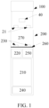
- the electronic vaporization device includes: a vaporizer 100, configured to store a liquid substrate and vaporize the liquid substrate to generate an aerosol; and a power supply mechanism 200, configured to supply power to the vaporizer 100.
- the power supply mechanism 200 includes a receiving cavity 270, arranged at an end in a length direction and configured to receive and accommodate at least a part of the vaporizer 100; and a first electrical contact 230, at least partially exposed on a surface of the receiving cavity 270, and configured to be electrically connected to the vaporizer 100 to supply power to the vaporizer 100 when at least a part of the vaporizer 100 is received and accommodated in the power supply mechanism 200.
- a second electrical contact 21 is arranged on an end portion of the vaporizer 100 opposite to the power supply mechanism 200 in the length direction, so that when the at least a part of the vaporizer 100 is received in the receiving cavity 270, the second electrical contact 21 is in contact with and abuts against the first electrical contact 230 to form an electrical connection.
- a seal member 260 is arranged in the power supply mechanism 200, and at least a part of an internal space of the power supply mechanism 200 is separated by the seal member 260 to form the receiving cavity 270.
- the seal member 260 is configured to extend along a cross section direction of the power supply mechanism 200, and is preferably prepared by a flexible material such as silica gel, so as to prevent the liquid substrate seeping from the vaporizer 100 to the receiving cavity 270 from flowing to a controller 220, a sensor 250, and another component inside the power supply mechanism 200.
- the power supply mechanism 200 further includes a core 210, configured to supply power and facing away from the receiving cavity 270 along a length direction; and a controller 220, arranged between the core 210 and an accommodating cavity, where the controller 220 operably guiding a current between the core 210 and the first electrical contact 230.
- the power supply mechanism 200 includes the sensor 250, which is configured to sense an inhalation flow generated by the vaporizer 100 during inhalation, so that the controller 220 controls the core 210 to output the current to the vaporizer 100 based on a detection signal of the sensor 250.
- a charging interface 240 is arranged on another end of the power supply mechanism 200 facing away from the receiving cavity 270, and is configured to supply power to the core 210.
- Embodiments in FIG. 2 to FIG. 4 are schematic structural diagrams of an embodiment of the vaporizer 100 in FIG. 1 , which includes a main housing 10, a porous body 30, and a heating element 40.
- the main housing 10 is substantially in a flat cylindrical shape, and certainly, a hollow interior of the main housing is a necessary functional device configured to store and vaporize the liquid substrate.
- a suction nozzle A configured to inhale an aerosol is arranged on an upper end of the main housing 10.
- a liquid storage cavity 12 configured to store the liquid substrate is arranged on an interior of the main housing 10.
- a vapor-gas transmission pipe 11 in an axial direction is arranged inside the main housing 10, and the liquid storage cavity 12 configured to store the liquid substrate is formed in a space between an outer wall of the vapor-gas transmission pipe 11 and an inner wall of the main housing 10.
- An upper end of the vapor-gas transmission pipe 11 opposite a proximal end 110 is in communication with the suction nozzle port A.
- the porous body 30 is configured to obtain the liquid substrate in the liquid storage cavity 12 through a liquid channel 13, and the liquid substrate is transmitted as indicated by arrow R1 in FIG. 2 .
- the porous body 30 includes a flat vaporization surface 310.
- the vaporization surface 310 is formed with the heating element 40 that heats at least part of the liquid substrate absorbed by the porous body 30 to generate the aerosol.
- a side of the porous body 30 facing away from the vaporization surface 310 is in fluid communication with the liquid channel 13 to absorb the liquid substrate, and then transfer the liquid substrate to the vaporization surface 310 to heat and vaporize.
- the porous body 30 includes flexible fibers, such as cotton fibers, non-woven fabrics, glass fiber ropes, or includes porous ceramics with a microporous structure, such as porous ceramics in shapes shown in FIG. 3 and FIG. 4 , and the specific structures can be found in patent CNCN212590248U.
- the heating element 40 may be combined onto the vaporization surface 310 of the porous body 30 through printing, deposition, sintering, physical assembly, or the like.
- the porous body 30 may have a flat or curved surface for supporting the heating element 40, and the heating element 40 is formed on the flat or curved surface of the porous body 30 through mounting, printing, deposition, and the like.
- the heating element 40 is made of a metal material with an appropriate impedance, a metal alloy, graphite, carbon, conductive ceramic, or another composite material of a ceramic material and a metal material.
- a suitable metal or alloy material includes at least one of nickel, cobalt, zirconium, titanium, nickel alloy, cobalt alloy, zirconium alloy, titanium alloy, nickel-chromium alloy, nickel-iron alloy, iron-chromium alloy, iron-chromium-aluminum alloy, titanium alloy, iron-manganese-aluminum based alloy, or stainless steel.
- the resistive material of the heating element 40 can select a metal or alloy material having a suitable resistance temperature coefficient, such as a positive temperature coefficient or a negative temperature coefficient, so that a heating circuit can be configured to generate heat and can be configured as a sensor for sensing real-time temperature of a vaporization component.
- FIG. 5 shows a schematic structural diagram of a vaporizer 100a according to another embodiment.
- the porous body 30a is configured in a shape of a hollow columnar extending in a longitudinal direction of the vaporizer 100a, and the heating element 40a is formed in a columnar hollow of the porous body 30a.
- the liquid substrate of the liquid storage cavity 20a is absorbed along an outer surface of the porous body 30a in a radial direction, and then transmitted to the heating element 40a on an inner surface to heat and vaporize to generate an aerosol; and the generated aerosol is outputted from the columnar hollow of the porous body 30a along a longitudinal direction of the vaporizer 100a.
- the resistance change of the heating element 40/40a in operation is detected by the controller 220 in an embodiment of this application, to identify and determine the vaporizer 100/100a.
- vaporizers 100/100a have heating elements 40/40a with different materials or models. Therefore, during heating, due to different initial resistance values and the respective material TCR (temperature coefficient of resistance), the resistance changes during heating are significantly different. In this way, the vaporizer 100/100a can be identified and determined based on the resistance change.
- the power supply mechanism 200 further includes a resistance detection circuit for detecting the resistance value of the heating element 40/40a.
- a structure of the resistance detection circuit in a conventional embodiment is shown in FIG. 6 , including: a standard resistor R1, configured to construct a voltage dividing circuit connected in series with the connected heating element 40/40a, where the voltage dividing circuit connected in series is turned on and grounded by a switch tube Q1 to form a circuit.
- the controller 220 may calculate the resistance value of the heating element 40/40a by sampling a voltage to ground Vabc of the standard resistor R1 and then through a formula of a partial pressure.
- resistors R2, R3, and R4 in the circuit shown in FIG. 6 are normal basic conventional functions such as voltage reduction and current limiting.
- the resistance detection circuit may further use a constant current source.
- the constant current source provides a constant current detection current to the heating elements 40/40a.
- the controller 220 samples the voltage of the heating element 40/40a at the constant current through a sampling pin, and then obtains the resistance value of the heating element 40/40a after calculation.
- FIG. 7 shows a curve showing a resistance change of a heating element 40 of a vaporizer 100 during continuous inhalation representing that a user inhales once according to an embodiment.
- each unit of the time axis is 60 ms
- an initial resistance value of the heating element 40 is 1.1 ohms
- the power output of the power supply mechanism 200 to the heating element 40 is constant at 10 W (generally, the output voltage of the core 210 in the electronic vaporization device in the art is 3.5 V after being fully charged. Combined with an actual output effective voltage of about 3.2 V and a heat loss, setting the output power to be constant at 10 W is the most commonly used constant power output value).
- the resistance value change of the heating element 40 includes three stages.
- S1 first stage It is an initial heating stage.
- the heating element 40 starts to heat up rapidly from a room temperature, and at the same time, the temperature has not been raised above a boiling point of the liquid substrate; and most of the heat at this stage is absorbed by the heating element 40, and correspondingly, the resistance value of the heating element 40 also increases rapidly due to the TCR.
- S2 second stage During this stage, the heating element 40 continues to heat up, and part of the heat of the heating element 40 is absorbed by a low-boiling component (such as propylene glycol, and a flavor component) in the liquid substrate to form the aerosol. In this stage, a resistance raising efficiency of the heating element 40 gradually decreases.
- a low-boiling component such as propylene glycol, and a flavor component
- S3 third stage In this stage, since the temperature of the heating element 40 rises to the temperature at which the liquid substrate is vaporized in large quantities, the heating efficiency of the heating element 40 is balanced with a vaporization efficiency of the liquid substrate; and in this stage, the resistance value of the heating element 40 is substantially constant and fluctuates in a generally small range until an end of the inhalation.
- a significant increase in resistance can be expressed as the resistance variation per unit time (that is, a slope of a tangent of the curve) or the increase in the resistance value beyond a certain reference threshold, that is, the resistance is considered to have risen significantly.
- the following show the sampling results of the resistance value of the heating element 40 in the power supply test performed by the power supply mechanism 200 to five different vaporizers 100 at a constant power of 7 W, respectively.
- the sampling of the vaporizer 100 in each embodiment is performed in two repetitions, which are denoted as "sample 1" and "sample 2" respectively.
- the specific sampling results are as follows, and the sampling results of each embodiment in the following table are averaged, and the resistance change curve with time is obtained by fitting as shown in FIG. 8 .
- the difference between the two replicates of the vaporizer 100 and the "sample 1" and “sample 2" in each embodiment is less than 1% of the sampled data, and the sampling error can be considered to meet the requirements. If the data is required to have high accuracy, more sampling times can be added, and then it is desirable to combine the above “sample 1" and “sample 2" data to take the average value as the detection result.
- an average initial resistance value of the heating element 40 of the vaporizer 100 of Embodiment 1 is 0.75 mQ
- an average initial resistance value of the heating element 40 of the vaporizer 100 of Embodiment 2 is 0.75 mQ
- an average initial resistance value of the heating element 40 of the vaporizer 100 in Embodiment 3 is 0.75 m ⁇
- an average initial resistance value of the heating element 40 of the vaporizer 100 in Embodiment 4 is 0.71 mQ
- an average initial resistance value of the heating element 40 of the vaporizer 100 in Embodiment 5 is 0.71 mQ.
- the material of the heating element 40 of the vaporizer 100 in Embodiment 1 is prepared by FeSi15 (FeSi alloy containing Si15%) with the TCR value of 1443 ppm; the material of the heating element 40 of the vaporizer 100 in Embodiment 2 is prepared by FeSi 10 with the TCR value of 1245 ppm; the material of the heating element 40 of the vaporizer 100 in Embodiment 3 is prepared by a stainless steel 304 with the TCR value of 1038 ppm; the material of the heating element 40 of the vaporizer 100 in Embodiment 4 is prepared by a stainless steel 317L with the TCR value of 956 ppm; and the material of the heating element 40 of the vaporizer 100 in Embodiment 5 is prepared by NiCr30Si1.45 alloy with a TCR value of 890 ppm.
- FIG. 8 shows the resistance value-time curve of the samples from Embodiment 1 to Embodiment 5.
- the vaporizer 100 in each embodiment has different TCR values for the heating elements 40 in the inhalation test, so that in the process of vaporizing the liquid substrate to generate the aerosol in the constant power output mode normally used in the art, the resistance varies differentially.
- the above resistance value-time curve or the rate of the resistance value can be used for identifying and distinguishing different vaporizers 100.
- the electric power supplied to the electric power by the core 210 is predetermined; and at the same time, in order to ensure that the detection results are not affected due to the different electric power supplied, the predetermined electric power supplied to the vaporizers is the same.
- the controller 220 stores a threshold range that is most adaptive for the resistance change of the heating element 40 in the vaporizer 100; and the sampled value of the resistance change obtained by sampling is compared with the stored threshold range based on the detection process, and it can be identified and determined whether the currently replaced vaporizer 100 is the most suitable vaporizer 100 by the comparison result. At the same time, when the above comparison results are inconsistent, the controller 220 prevents the core 210 from providing power to the vaporizer 100.
- the controller 220 can further calculate and obtain the TCR value of the heating element 40 based on the resistance change of the heating element 40 during operation, and then identify and determine whether the currently replaced vaporizer 100 is a suitable or adaptive vaporizer 100 based on the TCR value.
- the controller 220 may identify and distinguish different vaporizers 100 based on the resistance value and/or the rise amplitude or difference when the heating element 40 is raised to substantially constant.
- FIG. 9 shows a schematic diagram of identifying a vaporizer 100 by a period of time from 0 ms to 2000 ms at a predetermined time.
- the resistance change curves corresponding to the vaporizer 100 of different embodiments during this time period correspond to those shown in L1 to L5, respectively.
- slopes of the resistance change curve L1 to L5 of the vaporizer 100 in different embodiments when being raised from the initial value to basically stable are significantly different, and then different vaporizers 100 can be identified and distinguished by calculating the slopes.
- the above predetermined time may also select another time period such as 500 ms to 1600 ms, 300 ms to 1200 ms, and the like.
- another embodiment of this application further a method for identifying and distinguishing different vaporizers 100, which includes the following steps.
- S 10 Determine, based on a relationship between the power supplied to the heating element 40 of the vaporizer 100 and a resulting change in the resistance value of the heating element 40, information of the vaporizer 100.
- the power is supplied to the heating element 40 in a constant power output manner.
- the power provided to the vaporizer 100 in the process of identifying and distinguishing different vaporizers 100 above is the same as the output power set by the power supply mechanism 200 during the inhalation process, such as a constant power of 7 W or 10 W as described above.
- the detection method and step as described above are performed during a first puff after the user connects the vaporizer 100 to the power supply mechanism 200, which avoids a case in which the step as described above is automatically performed during a non-puffing process to supply power to the vaporizer 100 so that smoke generated is not inhaled by the user.
- the resistance temperature coefficient of the heating element 40 is determined based on the relationship between the power supplied to the heating element 40 of the vaporizer 100 and the resulting change in the resistance value of the heating element 40, the temperature coefficient of the resistance value is compared with the stored threshold range, and the vaporizer 100 is determined based on the comparison result.
- the content of Identifying and distinguishing the vaporizer 100 includes: a liquid substrate type, a heating mode, an anti-counterfeiting information, and the like. Further, the power supply mechanism 200 may prevent the core 210 from outputting power when the content identified above does not match the vaporizer 100 acceptable to the power supply mechanism 200.
- the power provided by the core 210 to the heating element 40 is changed or adjusted based on the comparison result.
- changing or adjusting the power provided by the core 210 to the heating element 40 may prevent power to the vaporizer 100 when the comparison result exceeds a maximum or minimum value of a preset threshold.
- a plurality of preset thresholds are included, and each preset threshold corresponds to a different optimal heating curve or power; and According to the comparison results, the core 210 can be further changed or adjusted accordingly to supply power to the vaporizer 100 with an optimal heating curve or power, respectively.
Landscapes
- Control Of Resistance Heating (AREA)
- Investigating Or Analyzing Materials By The Use Of Fluid Adsorption Or Reactions (AREA)
Abstract
Description
- This application claims priority to
Chinese Patent Application No. 202110284535.6, filed with the China National Intellectual Property Administration on March 16, 2021 - Embodiments of this application relate to the field of electronic vaporization technologies, and in particular, to an electronic vaporization device, a power supply mechanism, and a method for identifying a vaporizer.
- Tobacco products (such as cigarettes, cigars, and the like) burn tobacco during use to produce tobacco smoke. Attempts are made to replace these tobacco-burning products by manufacturing products that release compounds without burning tobacco.
- An example of this type of products is an electronic vaporization product, which vaporize a liquid substrate by heating to produce an inhalable vapor or aerosol. The liquid substrate may contain nicotine, and/or aromatics, and/or aerosol-generation substances (such as glycerin). Such frequently used electronic vaporization product is a modular construction and usually includes a replaceable vaporizer. The replaceable vaporizer has a storage component configured to accommodate the liquid substrate. The liquid substrate stored in the vaporizer may vary significantly in composition, taste, concentration, or another property, and consumers may wish to interchange the vaporizer at will. However, an optimal vaporization condition may depend on composition of the liquid substrate stored in the vaporizer. Therefore, it is desirable to include an automatic identification device in the vaporizer that can identify the replaceable vaporizer or the liquid substrate stored therein, to automatically change control settings for a vaporization device accordingly.
- An embodiment of this application provides an electronic vaporization device, including a vaporizer configured to vaporize a liquid substrate to generate an aerosol, and a power supply mechanism configured to supply power to the vaporizer. The vaporizer includes a heating element configured to heat and vaporize the liquid substrate. The power supply mechanism includes:
- a core, configured to supply power to the heating element; and
- a controller, configured to identify the vaporizer based on electric power provided by the core to the heating element and a resistance change generated by the heating element.
- In a preferred embodiment, the controller is configured to:
- determine a TCR value of the heating element based on electric power provided by the core to the heating element and a resistance change generated by the heating element; and identify the vaporizer based on the TCR value of the heating element.
- In a preferred embodiment, the resistance change includes a change curve of a resistance of the heating element with time.
- In a preferred implementation, the resistance change includes a resistance change rate of the heating element.
- In a preferred implementation, the resistance change includes a resistance value when the resistance of the heating element rises to be substantially constant, or a difference between the resistance value and an initial resistance value.
- In a preferred embodiment, the controller is configured to:
compare the resistance change of the heating element with a threshold range and change the electric power provided by the core to the heating element based on a comparison result. - In a preferred embodiment, the controller is configured to:
compare a resistance change rate of the heating element or a resistance variation within a preset time with a threshold range, and prevent the core from supplying power to the heating element when the resistance change rate or the resistance variation is greater than a maximum value of the threshold range or less than a minimum value of the preset threshold range. - In a preferred embodiment, the controller is configured to:
raise a resistance of the heating element to a substantially constant resistance value or compare a difference between the resistance value and an initial resistance value with a threshold range, and prevent the core from supplying power to the heating element when the resistance value or the difference is greater than a maximum value of the threshold range or less than a minimum value of the preset threshold range. - In a preferred embodiment, the core is configured to provide predetermined electric power to the heating element.
- In a preferred embodiment, the core is configured to supply power to the heating element in a manner of constant power output.
- Another embodiment of this application further provides a power supply mechanism, configured to supply power to a vaporizer of an electronic vaporization device, where the vaporizer includes a heating element configured to heat and vaporize a liquid substrate to generate an aerosol; the power supply mechanism includes:
- a core, configured to supply power to the heating element; and
- a controller, configured to identify the vaporizer based on electric power provided by the core to the heating element and a resistance change generated by the heating element.
- Another embodiment of this application further provides a method for identifying a vaporizer, where the vaporizer includes a heating element configured to heat and vaporize a liquid substrate to generate an aerosol; and the method includes following steps of:
supplying power to the heating element, and identifying the vaporizer based on an electric power provided to the heating element and a resistance change generated by the heating element. - Through the electronic vaporization device, the vaporizer can be automatically identified by detecting the resistance change of the heating element under electric power.
- One or more embodiments are exemplarily described with reference to the corresponding figures in the accompanying drawings, and the descriptions are not to be construed as limiting the embodiments. Elements in the accompanying drawings that have same reference numerals are represented as similar elements, and unless otherwise particularly stated, the figures in the accompanying drawings are not drawn to scale.
-
FIG. 1 is a schematic structural diagram of an electronic vaporization device according to an embodiment of this application. -
FIG. 2 is a schematic cross-sectional view of an embodiment of a vaporizer inFIG. 1 . -
FIG. 3 is a schematic structural diagram of a porous body inFIG. 2 from a perspective. -
FIG. 4 is a schematic structural diagram of a porous body inFIG. 2 from another perspective; -
FIG. 5 is a schematic cross-sectional view of another embodiment of a vaporizer inFIG. 1 . -
FIG. 6 is a schematic diagram of a resistance detection circuit according to an embodiment. -
FIG. 7 is a curve showing a resistance change of a heating element of a vaporizer during continuous inhalation representing that a user inhales once according to an embodiment. -
FIG. 8 is a curve showing a resistance change of heating elements of a plurality of vaporizers during continuous inhalation representing that a user inhales once according to an embodiment. -
FIG. 9 is a schematic diagram of a resistance change rate of heating elements within a predetermined time of a plurality of vaporizers inFIG. 8 . - For ease of understanding of this application, this application is described below in more detail with reference to the accompanying drawings and specific implementations.
- This application provides an electronic vaporization device. Referring to
FIG. 1 , the electronic vaporization device includes: avaporizer 100, configured to store a liquid substrate and vaporize the liquid substrate to generate an aerosol; and apower supply mechanism 200, configured to supply power to thevaporizer 100. - In an optional implementation, for example, as shown in
FIG. 1 , thepower supply mechanism 200 includes areceiving cavity 270, arranged at an end in a length direction and configured to receive and accommodate at least a part of thevaporizer 100; and a firstelectrical contact 230, at least partially exposed on a surface of thereceiving cavity 270, and configured to be electrically connected to thevaporizer 100 to supply power to thevaporizer 100 when at least a part of thevaporizer 100 is received and accommodated in thepower supply mechanism 200. - According to a preferred implementation shown in
FIG. 1 , a secondelectrical contact 21 is arranged on an end portion of thevaporizer 100 opposite to thepower supply mechanism 200 in the length direction, so that when the at least a part of thevaporizer 100 is received in thereceiving cavity 270, the secondelectrical contact 21 is in contact with and abuts against the firstelectrical contact 230 to form an electrical connection. - A
seal member 260 is arranged in thepower supply mechanism 200, and at least a part of an internal space of thepower supply mechanism 200 is separated by theseal member 260 to form thereceiving cavity 270. In the preferred implementation shown inFIG. 1 , theseal member 260 is configured to extend along a cross section direction of thepower supply mechanism 200, and is preferably prepared by a flexible material such as silica gel, so as to prevent the liquid substrate seeping from thevaporizer 100 to thereceiving cavity 270 from flowing to acontroller 220, asensor 250, and another component inside thepower supply mechanism 200. - In the preferred implementation shown in
FIG. 1 , thepower supply mechanism 200 further includes acore 210, configured to supply power and facing away from thereceiving cavity 270 along a length direction; and acontroller 220, arranged between thecore 210 and an accommodating cavity, where thecontroller 220 operably guiding a current between thecore 210 and the firstelectrical contact 230. - The
power supply mechanism 200 includes thesensor 250, which is configured to sense an inhalation flow generated by thevaporizer 100 during inhalation, so that thecontroller 220 controls thecore 210 to output the current to thevaporizer 100 based on a detection signal of thesensor 250. - Further, in the preferred implementation shown in
FIG. 1 , acharging interface 240 is arranged on another end of thepower supply mechanism 200 facing away from thereceiving cavity 270, and is configured to supply power to thecore 210. - Embodiments in
FIG. 2 to FIG. 4 are schematic structural diagrams of an embodiment of thevaporizer 100 inFIG. 1 , which includes amain housing 10, aporous body 30, and aheating element 40. - As shown in
FIG. 2 , themain housing 10 is substantially in a flat cylindrical shape, and certainly, a hollow interior of the main housing is a necessary functional device configured to store and vaporize the liquid substrate. A suction nozzle A configured to inhale an aerosol is arranged on an upper end of themain housing 10. - A
liquid storage cavity 12 configured to store the liquid substrate is arranged on an interior of themain housing 10. In a specific embodiment, a vapor-gas transmission pipe 11 in an axial direction is arranged inside themain housing 10, and theliquid storage cavity 12 configured to store the liquid substrate is formed in a space between an outer wall of the vapor-gas transmission pipe 11 and an inner wall of themain housing 10. An upper end of the vapor-gas transmission pipe 11 opposite a proximal end 110 is in communication with the suction nozzle port A. - The
porous body 30 is configured to obtain the liquid substrate in theliquid storage cavity 12 through aliquid channel 13, and the liquid substrate is transmitted as indicated by arrow R1 inFIG. 2 . Theporous body 30 includes aflat vaporization surface 310. Thevaporization surface 310 is formed with theheating element 40 that heats at least part of the liquid substrate absorbed by theporous body 30 to generate the aerosol. - Specifically, referring to
FIG. 3 and FIG. 4 , a side of theporous body 30 facing away from thevaporization surface 310 is in fluid communication with theliquid channel 13 to absorb the liquid substrate, and then transfer the liquid substrate to thevaporization surface 310 to heat and vaporize. - After assembly, two ends of the
heating element 40 abut against the secondelectrical contact 21 to conduct electricity, and theheating element 40 heats at least part of the liquid substrate of theporous body 30 to generate the aerosol during electrification. In an optional implementation, theporous body 30 includes flexible fibers, such as cotton fibers, non-woven fabrics, glass fiber ropes, or includes porous ceramics with a microporous structure, such as porous ceramics in shapes shown inFIG. 3 and FIG. 4 , and the specific structures can be found in patent CNCN212590248U. - The
heating element 40 may be combined onto thevaporization surface 310 of theporous body 30 through printing, deposition, sintering, physical assembly, or the like. In some other variant embodiments, theporous body 30 may have a flat or curved surface for supporting theheating element 40, and theheating element 40 is formed on the flat or curved surface of theporous body 30 through mounting, printing, deposition, and the like. - The
heating element 40 is made of a metal material with an appropriate impedance, a metal alloy, graphite, carbon, conductive ceramic, or another composite material of a ceramic material and a metal material. A suitable metal or alloy material includes at least one of nickel, cobalt, zirconium, titanium, nickel alloy, cobalt alloy, zirconium alloy, titanium alloy, nickel-chromium alloy, nickel-iron alloy, iron-chromium alloy, iron-chromium-aluminum alloy, titanium alloy, iron-manganese-aluminum based alloy, or stainless steel. The resistive material of theheating element 40 can select a metal or alloy material having a suitable resistance temperature coefficient, such as a positive temperature coefficient or a negative temperature coefficient, so that a heating circuit can be configured to generate heat and can be configured as a sensor for sensing real-time temperature of a vaporization component. -
FIG. 5 shows a schematic structural diagram of avaporizer 100a according to another embodiment. Theporous body 30a is configured in a shape of a hollow columnar extending in a longitudinal direction of thevaporizer 100a, and theheating element 40a is formed in a columnar hollow of theporous body 30a. In use, as represented by arrow R1, the liquid substrate of theliquid storage cavity 20a is absorbed along an outer surface of theporous body 30a in a radial direction, and then transmitted to theheating element 40a on an inner surface to heat and vaporize to generate an aerosol; and the generated aerosol is outputted from the columnar hollow of theporous body 30a along a longitudinal direction of thevaporizer 100a. - In order to distinguish whether the replaced
vaporizer 100/100a is an adaptive type, the resistance change of theheating element 40/40a in operation is detected by thecontroller 220 in an embodiment of this application, to identify and determine thevaporizer 100/100a. - Generally,
different vaporizers 100/100a haveheating elements 40/40a with different materials or models. Therefore, during heating, due to different initial resistance values and the respective material TCR (temperature coefficient of resistance), the resistance changes during heating are significantly different. In this way, thevaporizer 100/100a can be identified and determined based on the resistance change. - Further, in order to enable the
power supply mechanism 200 to detect the resistance change of theheating element 40/40a in real time, thepower supply mechanism 200 further includes a resistance detection circuit for detecting the resistance value of theheating element 40/40a. A structure of the resistance detection circuit in a conventional embodiment is shown inFIG. 6 , including:
a standard resistor R1, configured to construct a voltage dividing circuit connected in series with theconnected heating element 40/40a, where the voltage dividing circuit connected in series is turned on and grounded by a switch tube Q1 to form a circuit. In this case, thecontroller 220 may calculate the resistance value of theheating element 40/40a by sampling a voltage to ground Vabc of the standard resistor R1 and then through a formula of a partial pressure. - Certainly, other resistors R2, R3, and R4 in the circuit shown in
FIG. 6 are normal basic conventional functions such as voltage reduction and current limiting. - In another variant embodiment, the resistance detection circuit may further use a constant current source. When the
vaporizer 100/100a is coupled to thepower supply mechanism 200 to couple theheating element 40/40a to the circuit, the constant current source provides a constant current detection current to theheating elements 40/40a. Thecontroller 220 samples the voltage of theheating element 40/40a at the constant current through a sampling pin, and then obtains the resistance value of theheating element 40/40a after calculation. - For example,
FIG. 7 shows a curve showing a resistance change of aheating element 40 of avaporizer 100 during continuous inhalation representing that a user inhales once according to an embodiment. According to the test curve, each unit of the time axis is 60 ms, and the total detected data sampling time is 60 × 60 = 3600 ms = 3.6 s. During the test, an initial resistance value of theheating element 40 is 1.1 ohms, and the power output of thepower supply mechanism 200 to theheating element 40 is constant at 10 W (generally, the output voltage of the core 210 in the electronic vaporization device in the art is 3.5 V after being fully charged. Combined with an actual output effective voltage of about 3.2 V and a heat loss, setting the output power to be constant at 10 W is the most commonly used constant power output value). In the curve ofFIG. 7 , the resistance value change of theheating element 40 includes three stages. - S1 first stage: It is an initial heating stage. The
heating element 40 starts to heat up rapidly from a room temperature, and at the same time, the temperature has not been raised above a boiling point of the liquid substrate; and most of the heat at this stage is absorbed by theheating element 40, and correspondingly, the resistance value of theheating element 40 also increases rapidly due to the TCR. - S2 second stage: During this stage, the
heating element 40 continues to heat up, and part of the heat of theheating element 40 is absorbed by a low-boiling component (such as propylene glycol, and a flavor component) in the liquid substrate to form the aerosol. In this stage, a resistance raising efficiency of theheating element 40 gradually decreases. - S3 third stage: In this stage, since the temperature of the
heating element 40 rises to the temperature at which the liquid substrate is vaporized in large quantities, the heating efficiency of theheating element 40 is balanced with a vaporization efficiency of the liquid substrate; and in this stage, the resistance value of theheating element 40 is substantially constant and fluctuates in a generally small range until an end of the inhalation. - In the above changes in the actual resistance detected in conjunction with specific embodiments, a significant increase in resistance can be expressed as the resistance variation per unit time (that is, a slope of a tangent of the curve) or the increase in the resistance value beyond a certain reference threshold, that is, the resistance is considered to have risen significantly.
- In order to identify and distinguish
different vaporizers 100, the following show the sampling results of the resistance value of theheating element 40 in the power supply test performed by thepower supply mechanism 200 to fivedifferent vaporizers 100 at a constant power of 7 W, respectively. Certainly, to eliminate an error of a single sampling of the sampling detection result of thevaporizer 100 of each embodiment, the sampling of thevaporizer 100 in each embodiment is performed in two repetitions, which are denoted as "sample 1" and "sample 2" respectively. The specific sampling results are as follows, and the sampling results of each embodiment in the following table are averaged, and the resistance change curve with time is obtained by fitting as shown inFIG. 8 .Table 1 Sampling time/ms Sampling resistance value/mΩ Embodiment 1 Embodiment 2 Embodiment 3 Embodiment 4 Embodiment 5 Sample 1 Sample 2 Sample 1 Sample 2 Sample 1 Sample 2 Sample 1 Sample 2 Sample 1 Sample 2 0 752 758 757 760 750 754 717 724 710 713 20 916 911 860 859 856 851 814 830 801 810 80 912 919 870 869 852 859 806 821 798 816 140 913 929 884 882 853 868 821 839 806 824 200 915 928 885 889 855 867 834 848 810 827 260 933 933 888 889 872 872 831 844 813 836 320 923 933 893 895 863 872 841 849 817 836 380 938 942 897 897 877 880 842 858 832 831 440 942 945 898 895 880 883 850 852 836 842 500 941 941 900 912 879 879 849 846 826 843 560 943 956 910 907 881 893 855 853 837 839 620 954 950 911 914 892 888 847 848 838 844 680 945 945 907 907 883 883 854 865 830 847 740 957 950 911 917 894 888 860 863 836 847 800 949 959 912 915 887 896 852 860 834 848 860 964 964 916 918 901 901 861 864 843 844 920 959 954 918 918 896 892 860 870 844 845 980 950 956 917 916 888 893 852 860 838 855 1040 961 963 924 920 898 900 853 869 845 842 1100 956 957 915 929 893 894 859 868 837 842 1160 963 962 920 929 900 899 856 877 846 843 1220 970 967 919 921 907 904 858 864 843 852 1280 964 972 927 931 901 908 869 869 844 846 1340 965 970 922 923 902 907 858 869 848 852 1400 961 974 923 927 898 910 859 868 841 858 1460 958 961 932 925 895 898 864 876 846 857 1520 966 969 928 924 903 906 866 871 844 858 1580 968 974 928 924 905 910 869 881 844 852 1640 977 979 926 932 913 915 871 877 852 855 1700 969 976 923 923 906 912 872 880 845 852 1760 968 972 936 934 905 908 864 872 840 850 1820 969 974 938 923 906 910 867 883 844 852 1880 966 980 936 929 903 916 859 884 848 854 1940 974 975 934 927 910 911 862 873 851 849 2000 969 967 927 927 906 904 874 876 850 846 2060 976 968 933 931 912 905 868 866 850 844 2120 972 979 934 930 908 915 871 877 852 848 2180 979 968 931 931 915 905 869 868 847 850 2240 972 978 926 923 908 914 864 872 857 853 2300 962 984 930 925 899 920 867 878 842 858 2360 978 984 933 935 914 920 872 864 853 846 2420 981 973 930 929 917 909 875 874 850 851 2480 973 977 927 925 909 913 868 873 858 846 2540 973 980 936 929 909 916 867 873 856 847 2600 974 970 933 937 910 907 866 867 855 849 2660 972 980 932 935 908 916 874 874 850 845 2720 972 973 927 929 908 909 869 871 857 843 2780 985 975 932 929 921 911 864 876 842 852 2840 980 969 934 933 916 906 869 871 853 855 2900 980 979 926 932 916 915 866 879 842 843 2960 976 976 935 935 912 912 862 877 845 846 3020 969 977 926 931 906 913 866 873 845 852 3080 982 977 929 926 918 913 868 877 841 841 3140 989 966 928 934 924 903 873 868 854 850 3200 987 980 934 926 922 916 876 870 844 849 3260 984 968 932 934 920 905 869 869 845 853 3320 973 972 922 926 909 908 873 879 844 850 3380 973 976 935 929 909 912 871 879 852 855 3440 976 967 938 931 912 904 874 865 849 849 3500 985 979 924 933 921 915 875 877 848 841 3560 980 975 929 936 916 911 882 873 845 850 3620 975 978 925 928 911 914 884 871 847 844 3680 983 970 928 925 919 907 888 872 849 848 3740 968 980 929 930 905 916 880 869 854 848 3800 982 978 925 929 918 914 881 878 846 844 3860 970 970 931 932 907 907 873 870 845 845 3920 969 980 924 926 906 916 887 880 854 853 3980 988 982 929 927 923 918 889 873 844 848 4040 974 974 932 928 910 910 872 878 852 844 4100 978 985 929 933 914 921 877 867 846 847 4160 983 973 937 930 919 909 865 878 848 849 4220 981 972 931 924 917 908 878 868 841 847 4280 979 979 927 932 915 915 874 869 852 846 4340 969 972 929 936 906 908 872 874 854 843 4400 978 980 934 928 914 916 878 875 848 856 4460 983 980 930 928 919 916 867 872 852 844 4520 975 972 924 934 911 908 874 869 842 843 4580 968 976 937 934 905 912 871 878 845 847 4640 976 970 938 936 912 907 874 871 853 847 4700 982 980 937 923 918 916 864 875 843 855 4760 978 973 925 932 914 909 878 875 853 848 4820 975 973 927 929 911 909 869 874 851 841 4880 970 978 937 929 907 914 877 871 847 855 4940 967 970 924 928 904 907 871 869 852 849 5000 972 966 927 921 908 903 869 875 849 846 5060 972 981 931 925 908 917 866 868 848 848 5120 979 972 927 930 915 908 878 867 845 851 5180 976 979 931 930 912 915 869 863 854 860 5240 967 969 930 925 904 906 871 865 842 856 5300 974 979 935 934 910 915 872 875 845 851 5360 980 972 929 924 916 908 880 876 851 856 5420 984 972 933 933 920 908 873 879 849 846 5480 972 985 936 936 908 921 881 879 851 857 5540 972 973 927 935 908 909 871 871 851 856 5600 972 984 936 931 908 920 877 878 847 849 - As can be seen from Table 1 and
FIG. 8 above, the difference between the two replicates of thevaporizer 100 and the "sample 1" and "sample 2" in each embodiment is less than 1% of the sampled data, and the sampling error can be considered to meet the requirements. If the data is required to have high accuracy, more sampling times can be added, and then it is desirable to combine the above "sample 1" and "sample 2" data to take the average value as the detection result. - Further, according to Table 1 above, an average initial resistance value of the
heating element 40 of thevaporizer 100 ofEmbodiment 1 is 0.75 mQ, an average initial resistance value of theheating element 40 of thevaporizer 100 ofEmbodiment 2 is 0.75 mQ, an average initial resistance value of theheating element 40 of thevaporizer 100 inEmbodiment 3 is 0.75 mΩ, an average initial resistance value of theheating element 40 of thevaporizer 100 inEmbodiment 4 is 0.71 mQ, and an average initial resistance value of theheating element 40 of thevaporizer 100 inEmbodiment 5 is 0.71 mQ. The initial values of theheating element 40 inEmbodiment 1 toEmbodiment 3 are basically the same; and the initial values of theheating elements 40 ofEmbodiment 4 andEmbodiment 5 are basically the same. - Further, the material of the
heating element 40 of thevaporizer 100 inEmbodiment 1 is prepared by FeSi15 (FeSi alloy containing Si15%) with the TCR value of 1443 ppm; the material of theheating element 40 of thevaporizer 100 inEmbodiment 2 is prepared byFeSi 10 with the TCR value of 1245 ppm; the material of theheating element 40 of thevaporizer 100 inEmbodiment 3 is prepared by a stainless steel 304 with the TCR value of 1038 ppm; the material of theheating element 40 of thevaporizer 100 inEmbodiment 4 is prepared by a stainless steel 317L with the TCR value of 956 ppm; and the material of theheating element 40 of thevaporizer 100 inEmbodiment 5 is prepared by NiCr30Si1.45 alloy with a TCR value of 890 ppm. -
FIG. 8 shows the resistance value-time curve of the samples fromEmbodiment 1 toEmbodiment 5. As can be clearly seen fromFIG. 8 , thevaporizer 100 in each embodiment has different TCR values for theheating elements 40 in the inhalation test, so that in the process of vaporizing the liquid substrate to generate the aerosol in the constant power output mode normally used in the art, the resistance varies differentially. As a result, the above resistance value-time curve or the rate of the resistance value can be used for identifying and distinguishingdifferent vaporizers 100. - Further, during testing the
vaporizer 100 in each embodiment, the electric power supplied to the electric power by thecore 210 is predetermined; and at the same time, in order to ensure that the detection results are not affected due to the different electric power supplied, the predetermined electric power supplied to the vaporizers is the same. - Further, the
controller 220 stores a threshold range that is most adaptive for the resistance change of theheating element 40 in thevaporizer 100; and the sampled value of the resistance change obtained by sampling is compared with the stored threshold range based on the detection process, and it can be identified and determined whether the currently replacedvaporizer 100 is the mostsuitable vaporizer 100 by the comparison result. At the same time, when the above comparison results are inconsistent, thecontroller 220 prevents the core 210 from providing power to thevaporizer 100. - Further, in a preferred embodiment, the
controller 220 can further calculate and obtain the TCR value of theheating element 40 based on the resistance change of theheating element 40 during operation, and then identify and determine whether the currently replacedvaporizer 100 is a suitable oradaptive vaporizer 100 based on the TCR value. - Further, according to the sampling data of
FIG. 8 and the table above, it can be seen that fordifferent vaporizers 100 at constant power, the resistance value of theheating element 40 is raised to be substantially constant, and/or the difference between the resistance value and the initial resistance value when theheating element 40 is raised to be substantially constant is different, which is caused by different TCRs. Further, in another embodiment, thecontroller 220 may identify and distinguishdifferent vaporizers 100 based on the resistance value and/or the rise amplitude or difference when theheating element 40 is raised to substantially constant. - Further, as can be seen from the sampling data in
FIG. 8 and the table above, at constant power fordifferent vaporizers 100, the resistance change rate is also different due to the different TCRs, and the resistance change rate of theheating element 40 within a predetermined time is different. As a result, thecontroller 220 can identify and distinguishdifferent vaporizers 100 according to the resistance change rate of theheating element 40 during a predetermined time. For example,FIG. 9 shows a schematic diagram of identifying avaporizer 100 by a period of time from 0 ms to 2000 ms at a predetermined time. According toFIG. 9 , the resistance change curves corresponding to thevaporizer 100 of different embodiments during this time period correspond to those shown in L1 to L5, respectively. In addition, slopes of the resistance change curve L1 to L5 of thevaporizer 100 in different embodiments when being raised from the initial value to basically stable are significantly different, and thendifferent vaporizers 100 can be identified and distinguished by calculating the slopes. - In another optional embodiment, the above predetermined time may also select another time period such as 500 ms to 1600 ms, 300 ms to 1200 ms, and the like.
- Based on the above, another embodiment of this application further a method for identifying and distinguishing
different vaporizers 100, which includes the following steps. - S 10: Determine, based on a relationship between the power supplied to the
heating element 40 of thevaporizer 100 and a resulting change in the resistance value of theheating element 40, information of thevaporizer 100. - In the process of providing the above power, according to the conventional embodiments of the products in the art, in a more preferred embodiment, the power is supplied to the
heating element 40 in a constant power output manner. In a more preferred embodiment, the power provided to thevaporizer 100 in the process of identifying and distinguishingdifferent vaporizers 100 above is the same as the output power set by thepower supply mechanism 200 during the inhalation process, such as a constant power of 7 W or 10 W as described above. - Further, in a preferred embodiment, the detection method and step as described above are performed during a first puff after the user connects the
vaporizer 100 to thepower supply mechanism 200, which avoids a case in which the step as described above is automatically performed during a non-puffing process to supply power to thevaporizer 100 so that smoke generated is not inhaled by the user. - Further, the resistance temperature coefficient of the
heating element 40 is determined based on the relationship between the power supplied to theheating element 40 of thevaporizer 100 and the resulting change in the resistance value of theheating element 40, the temperature coefficient of the resistance value is compared with the stored threshold range, and thevaporizer 100 is determined based on the comparison result. - The content of Identifying and distinguishing the
vaporizer 100 includes: a liquid substrate type, a heating mode, an anti-counterfeiting information, and the like. Further, thepower supply mechanism 200 may prevent the core 210 from outputting power when the content identified above does not match thevaporizer 100 acceptable to thepower supply mechanism 200. - Further, based on comparing the change in the resistance value generated by the
heating element 40 within a predetermined time with the preset threshold, the power provided by thecore 210 to theheating element 40 is changed or adjusted based on the comparison result. In an optional embodiment, changing or adjusting the power provided by thecore 210 to theheating element 40 may prevent power to thevaporizer 100 when the comparison result exceeds a maximum or minimum value of a preset threshold. Alternatively, in a further optional embodiment, a plurality of preset thresholds are included, and each preset threshold corresponds to a different optimal heating curve or power; and According to the comparison results, thecore 210 can be further changed or adjusted accordingly to supply power to thevaporizer 100 with an optimal heating curve or power, respectively. - It should be noted that the specification and the accompanying drawings of this application provide preferred embodiments of this application, but is not limited to the embodiments described in this specification. Further, a person of ordinary skill in the art may make improvements or modifications according to the foregoing descriptions, and all the improvements and modifications shall fall within the protection scope of the appended claims of this application.
Claims (11)
- An electronic vaporization device, comprising a vaporizer configured to vaporize a liquid substrate to generate an aerosol, and a power supply mechanism configured to supply power to the vaporizer, wherein the vaporizer comprises a heating element configured to heat and vaporize the liquid substrate, and the power supply mechanism comprises:a core, configured to supply power to the heating element; anda controller, configured to identify the vaporizer based on electric power provided by the core to the heating element and a resistance change generated by the heating element.
- The electronic vaporization device according to claim 1, wherein the resistance change comprises a change curve of a resistance of the heating element with time.
- The electronic vaporization device according to claim 1, wherein the resistance change comprises a resistance change rate of the heating element.
- The electronic vaporization device according to claim 1, wherein the resistance change comprises a resistance value when the resistance of the heating element rises to be substantially constant, or a difference between the resistance value and an initial resistance value.
- The electronic vaporization device according to claim 1, wherein the controller is configured to:
compare the resistance change of the heating element with a threshold range and change the electric power provided by the core to the heating element based on a comparison result. - The electronic vaporization device according to claim 5, wherein the controller is configured to:
compare a resistance change rate of the heating element or a resistance variation within a preset time with a threshold range, and prevent the core from supplying power to the heating element when the resistance change rate or the resistance variation is greater than a maximum value of the threshold range or less than a minimum value of the preset threshold range. - The electronic vaporization device according to claim 5, wherein the controller is configured to:
raise a resistance of the heating element to a substantially constant resistance value or compare a difference between the resistance value and an initial resistance value with a threshold range, and prevent the core from supplying power to the heating element when the resistance value or the difference is greater than a maximum value of the threshold range or less than a minimum value of the preset threshold range. - The electronic vaporization device according to any of claims 1 to 7, wherein the core is configured to provide predetermined electric power to the heating element.
- The electronic vaporization device according to claim 8, wherein the core is configured to supply power to the heating element in a manner of constant power output.
- A power supply mechanism, configured to supply power to a vaporizer of an electronic vaporization device, wherein the vaporizer comprises a heating element configured to heat and vaporize a liquid substrate to generate an aerosol, and the power supply mechanism comprises:a core, configured to supply power to the heating element; anda controller, configured to identify the vaporizer based on electric power provided by the core to the heating element and a resistance change generated by the heating element.
- A method for identifying a vaporizer, wherein the vaporizer comprises a heating element configured to heat and vaporize a liquid substrate to generate an aerosol, and the method comprises following steps of:
supplying power to the heating element, and identifying the vaporizer based on an electric power provided to the heating element and a resistance change generated by the heating element.
Applications Claiming Priority (2)
| Application Number | Priority Date | Filing Date | Title |
|---|---|---|---|
| CN202110284535.6A CN115067564A (en) | 2021-03-16 | 2021-03-16 | Electronic atomization device, power supply mechanism and atomizer identification method |
| PCT/CN2022/080990 WO2022194161A1 (en) | 2021-03-16 | 2022-03-15 | Electronic atomizing device, power supply mechanism, and recognition method for atomizer |
Publications (2)
| Publication Number | Publication Date |
|---|---|
| EP4309523A1 true EP4309523A1 (en) | 2024-01-24 |
| EP4309523A4 EP4309523A4 (en) | 2025-01-08 |
Family
ID=83245839
Family Applications (1)
| Application Number | Title | Priority Date | Filing Date |
|---|---|---|---|
| EP22770514.2A Pending EP4309523A4 (en) | 2021-03-16 | 2022-03-15 | ELECTRONIC ATOMIZATION DEVICE, POWER SUPPLY MECHANISM AND DETECTION METHOD FOR ATOMIZERS |
Country Status (4)
| Country | Link |
|---|---|
| US (1) | US20250072500A1 (en) |
| EP (1) | EP4309523A4 (en) |
| CN (1) | CN115067564A (en) |
| WO (1) | WO2022194161A1 (en) |
Families Citing this family (4)
| Publication number | Priority date | Publication date | Assignee | Title |
|---|---|---|---|---|
| CN119054980A (en) | 2023-06-01 | 2024-12-03 | 深圳市合元科技有限公司 | Aerosol generating device and aerosol generating system |
| CN119184377A (en) * | 2023-06-25 | 2024-12-27 | 思摩尔国际控股有限公司 | Electronic atomizing equipment and control method and device thereof |
| CN119344507A (en) | 2023-07-24 | 2025-01-24 | 深圳市合元科技有限公司 | Aerosol generating device and aerosol generating system |
| CN119949577A (en) * | 2023-11-07 | 2025-05-09 | 深圳市合元科技有限公司 | Electronic atomization device and control method thereof, and aerosol generating device |
Family Cites Families (12)
| Publication number | Priority date | Publication date | Assignee | Title |
|---|---|---|---|---|
| KR20150080506A (en) * | 2012-10-17 | 2015-07-09 | 넥타르 테라퓨틱스 | Methods and systems for identifying dry nebulizer elements |
| GB2529629B (en) * | 2014-08-26 | 2021-05-12 | Nicoventures Trading Ltd | Electronic aerosol provision system |
| CN112790443B (en) * | 2015-03-26 | 2024-10-18 | 菲利普莫里斯生产公司 | Heater Management |
| CN204613780U (en) * | 2015-05-06 | 2015-09-02 | 陈镇江 | One can thermostatically controlled electronic cigarette control circuit |
| GB2566185B (en) * | 2016-05-25 | 2022-02-16 | Juul Labs Inc | Control of an electronic vaporizer |
| CN106820275A (en) * | 2017-03-22 | 2017-06-13 | 颐中(青岛)实业有限公司 | A kind of temperature control electronic cigarette for being adapted to various heating wires |
| CN206714080U (en) * | 2017-03-22 | 2017-12-08 | 颐中(青岛)实业有限公司 | A kind of temperature control electronic cigarette for being adapted to a variety of heating wires |
| EP3701819A4 (en) * | 2017-10-24 | 2021-11-10 | Japan Tobacco Inc. | AEROSOL GENERATOR |
| JP7630432B2 (en) * | 2018-10-08 | 2025-02-17 | ジュール・ラブズ・インコーポレイテッド | Heating elements |
| CN109330032B (en) * | 2018-11-30 | 2023-11-03 | 中山市胜裕丰贸易有限公司 | An electronic cigarette control method and electronic cigarette |
| CN109588785B (en) * | 2019-01-21 | 2023-12-19 | 深圳市太美亚电子科技有限公司 | An anti-dry burning control circuit for electronic cigarettes |
| CN112931962B (en) * | 2021-03-15 | 2023-10-20 | 深圳麦克韦尔科技有限公司 | Method for identifying atomizer and battery pole applied by same |
-
2021
- 2021-03-16 CN CN202110284535.6A patent/CN115067564A/en active Pending
-
2022
- 2022-03-15 EP EP22770514.2A patent/EP4309523A4/en active Pending
- 2022-03-15 US US18/282,539 patent/US20250072500A1/en active Pending
- 2022-03-15 WO PCT/CN2022/080990 patent/WO2022194161A1/en not_active Ceased
Also Published As
| Publication number | Publication date |
|---|---|
| EP4309523A4 (en) | 2025-01-08 |
| CN115067564A (en) | 2022-09-20 |
| US20250072500A1 (en) | 2025-03-06 |
| WO2022194161A1 (en) | 2022-09-22 |
Similar Documents
| Publication | Publication Date | Title |
|---|---|---|
| US20250072500A1 (en) | Electronic vaporization device, power supply mechanism, and method for identifying vaporizer | |
| US12127600B2 (en) | Electrically operated aerosol-generating system and methods for detecting heater conditions in the system | |
| EP3799749B1 (en) | Aerosol generating device | |
| EP3402349B1 (en) | Current measuring in an aerosol delivery device by means of a hall effect sensor | |
| WO2020178671A1 (en) | Temperature control circuitry for an aerosol delivery device | |
| US20260048211A1 (en) | Analog control component for an aerosol delivery device | |
| KR20170041772A (en) | Electronic aerosol provision system | |
| US20210321674A1 (en) | Pressure-sensing user interface for an aerosol delivery device | |
| EP4412480B1 (en) | An aerosol-generating system and method of aerosol production with adaptive power control | |
| EP4018854A1 (en) | Aerosol-generating device comprising electrode | |
| CN215347063U (en) | Electronic atomization device and power supply mechanism | |
| EP4393332A1 (en) | Aerosol generating device and control method therefor | |
| KR102714160B1 (en) | Aerosol generating device including an electrode | |
| EP4353103A1 (en) | Electronic atomization device, power mechanism and control method | |
| CN222466096U (en) | Aerosol generating device | |
| KR20260003038A (en) | Aerosol generating device that detects airflow | |
| RU2839968C2 (en) | Device for generating aerosol (versions) and method of controlling such device | |
| WO2026032126A1 (en) | Atomization assembly and electronic atomization apparatus | |
| JP2026515847A (en) | Aerosol generator with airflow detection function | |
| KR20260003139A (en) | Aerosol generating device using dual mode heating | |
| CN120899027A (en) | Aerosol generating device | |
| KR20230110149A (en) | Aerosol generating device and method thereof | |
| HK1255893B (en) | Current measuring in an aerosol delivery device by means of a hall effect sensor |
Legal Events
| Date | Code | Title | Description |
|---|---|---|---|
| STAA | Information on the status of an ep patent application or granted ep patent |
Free format text: STATUS: THE INTERNATIONAL PUBLICATION HAS BEEN MADE |
|
| PUAI | Public reference made under article 153(3) epc to a published international application that has entered the european phase |
Free format text: ORIGINAL CODE: 0009012 |
|
| STAA | Information on the status of an ep patent application or granted ep patent |
Free format text: STATUS: REQUEST FOR EXAMINATION WAS MADE |
|
| 17P | Request for examination filed |
Effective date: 20231011 |
|
| AK | Designated contracting states |
Kind code of ref document: A1 Designated state(s): AL AT BE BG CH CY CZ DE DK EE ES FI FR GB GR HR HU IE IS IT LI LT LU LV MC MK MT NL NO PL PT RO RS SE SI SK SM TR |
|
| DAV | Request for validation of the european patent (deleted) | ||
| DAX | Request for extension of the european patent (deleted) | ||
| REG | Reference to a national code |
Ref country code: DE Ref legal event code: R079 Free format text: PREVIOUS MAIN CLASS: A24F0040400000 Ipc: A24F0040500000 |
|
| STAA | Information on the status of an ep patent application or granted ep patent |
Free format text: STATUS: EXAMINATION IS IN PROGRESS |
|
| A4 | Supplementary search report drawn up and despatched |
Effective date: 20241210 |
|
| RIC1 | Information provided on ipc code assigned before grant |
Ipc: A24F 40/10 20200101ALN20241204BHEP Ipc: A24F 40/40 20200101ALN20241204BHEP Ipc: A24F 40/57 20200101ALN20241204BHEP Ipc: A24F 40/42 20200101ALI20241204BHEP Ipc: A24F 40/50 20200101AFI20241204BHEP |
|
| 17Q | First examination report despatched |
Effective date: 20241223 |