EP4307941B1 - Aerosol-generating device with venting means - Google Patents
Aerosol-generating device with venting means Download PDFInfo
- Publication number
- EP4307941B1 EP4307941B1 EP22716389.6A EP22716389A EP4307941B1 EP 4307941 B1 EP4307941 B1 EP 4307941B1 EP 22716389 A EP22716389 A EP 22716389A EP 4307941 B1 EP4307941 B1 EP 4307941B1
- Authority
- EP
- European Patent Office
- Prior art keywords
- aerosol
- generating device
- housing compartment
- venting means
- generating
- Prior art date
- Legal status (The legal status is an assumption and is not a legal conclusion. Google has not performed a legal analysis and makes no representation as to the accuracy of the status listed.)
- Active
Links
Images


Classifications
-
- A—HUMAN NECESSITIES
- A24—TOBACCO; CIGARS; CIGARETTES; SIMULATED SMOKING DEVICES; SMOKERS' REQUISITES
- A24F—SMOKERS' REQUISITES; MATCH BOXES; SIMULATED SMOKING DEVICES
- A24F40/00—Electrically operated smoking devices; Component parts thereof; Manufacture thereof; Maintenance or testing thereof; Charging means specially adapted therefor
- A24F40/40—Constructional details, e.g. connection of cartridges and battery parts
- A24F40/48—Fluid transfer means, e.g. pumps
- A24F40/485—Valves; Apertures
-
- A—HUMAN NECESSITIES
- A24—TOBACCO; CIGARS; CIGARETTES; SIMULATED SMOKING DEVICES; SMOKERS' REQUISITES
- A24F—SMOKERS' REQUISITES; MATCH BOXES; SIMULATED SMOKING DEVICES
- A24F40/00—Electrically operated smoking devices; Component parts thereof; Manufacture thereof; Maintenance or testing thereof; Charging means specially adapted therefor
- A24F40/40—Constructional details, e.g. connection of cartridges and battery parts
- A24F40/46—Shape or structure of electric heating means
-
- A—HUMAN NECESSITIES
- A24—TOBACCO; CIGARS; CIGARETTES; SIMULATED SMOKING DEVICES; SMOKERS' REQUISITES
- A24F—SMOKERS' REQUISITES; MATCH BOXES; SIMULATED SMOKING DEVICES
- A24F40/00—Electrically operated smoking devices; Component parts thereof; Manufacture thereof; Maintenance or testing thereof; Charging means specially adapted therefor
- A24F40/20—Devices using solid inhalable precursors
-
- A—HUMAN NECESSITIES
- A24—TOBACCO; CIGARS; CIGARETTES; SIMULATED SMOKING DEVICES; SMOKERS' REQUISITES
- A24F—SMOKERS' REQUISITES; MATCH BOXES; SIMULATED SMOKING DEVICES
- A24F40/00—Electrically operated smoking devices; Component parts thereof; Manufacture thereof; Maintenance or testing thereof; Charging means specially adapted therefor
- A24F40/40—Constructional details, e.g. connection of cartridges and battery parts
- A24F40/46—Shape or structure of electric heating means
- A24F40/465—Shape or structure of electric heating means specially adapted for induction heating
-
- A—HUMAN NECESSITIES
- A24—TOBACCO; CIGARS; CIGARETTES; SIMULATED SMOKING DEVICES; SMOKERS' REQUISITES
- A24F—SMOKERS' REQUISITES; MATCH BOXES; SIMULATED SMOKING DEVICES
- A24F40/00—Electrically operated smoking devices; Component parts thereof; Manufacture thereof; Maintenance or testing thereof; Charging means specially adapted therefor
- A24F40/90—Arrangements or methods specially adapted for charging batteries thereof
- A24F40/95—Arrangements or methods specially adapted for charging batteries thereof structurally associated with cases
Definitions
- the present invention relates to an aerosol-generating device with a sealed housing compartment.
- the present invention also relates to a method for operating an aerosol-generating system and a use of a venting membrane in an aerosol-generating device.
- aerosol-generating system is an electrically operated smoking system.
- Known handheld electrically operated smoking systems typically comprise an aerosol-generating device comprising a battery, control electronics and an electric heater for heating an aerosol-generating article designed specifically for use with the aerosol-generating device.
- the aerosol-generating article comprises an aerosol-forming substrate, such as a tobacco rod or a tobacco plug, and the heater contained within the aerosol-generating device is inserted into or located around the aerosol-forming substrate when the aerosol-generating article is inserted into the aerosol-generating device.
- the aerosol-generating article may comprise a capsule containing an aerosol-forming substrate, such as loose tobacco.
- an aerosol delivery device that utilizes electrically generated heat to produce aerosol is known.
- a light window of the aerosol delivery device is covered with a selectively permeable venting material.
- an aerosol-generating device comprising a heating chamber adapted to receive an aerosol-generating article, a heating element, a sealed housing compartment, and a venting means adapted to allow gas flow from the sealed housing compartment to the outside of the aerosol-generating device to compensate for heat expansion of gas inside the housing compartment due to heating operation of the heating element.
- the transverse direction of the aerosol-generating device may be perpendicular to a longitudinal direction of the aerosol-generating device.
- the longitudinal direction may be the main extension direction of the aerosol-generating device, namely the direction in which the aerosol-generating device has its greatest length.
- the longitudinal direction is the height direction and the transversal direction may be a horizontal direction.
- the transversal direction may be perpendicular to a width direction of the aerosol-generating device. Any indications in the following regarding "upper” and "lower” are with respect to the longitudinal direction being the height direction.
- An aerosol-generating article may be inserted in the heating chamber of the aerosol-generating device in the longitudinal direction, such that the aerosol-generating article is at least partially arranged in a heating chamber.
- a mouth-end portion of the aerosol-generating article may protrude from the heating chamber in the longitudinal direction.
- the housing compartment is sealed to prevent the ingress of dust or ingress of dust and water.
- the housing compartment may comprise a bottom plate. The bottom plate may sealingly close the lower side of the housing compartment. At least one of the heating element, control electronics and a battery are arranged in the housing compartment.
- the heating element is provided in the sealed housing compartment.
- the heating element may be an electrical resistance heating element, or an inductive heating element, such as an inductor, for example a coil.
- Control electronics may be provided, which are adapted to control the heating element to swiftly heat the aerosol-generating article in the heating chamber.
- the heating element and the control electronics of the device may be adapted, such that the temperature of the heating element is in between 70 degrees Celsius and 130 degrees Celsius, or in between 80 degrees Celsius and 120 degrees Celsius, or in between 80 degrees Celsius and 100 degrees Celsius.
- the heating element and the control electronics may be adapted, such that the heating time for heating the heating element from ambient temperature to at least 80 degrees Celsius is less than 5 seconds or less than 3 seconds.
- the heating element and the control electronics of the device may be adapted, such that the aerosol-generating article is heated to a temperature between 70 degrees Celsius and 130 degrees Celsius, or in between 80 degrees Celsius and 120 degrees Celsius, or in between 80 degrees Celsius and 100 degrees Celsius.
- the heating element and the control electronics may be adapted, such that the heating time for heating the aerosol-generating article from ambient temperature to at least 80 degrees Celsius is less than 5 seconds or less than 3 seconds.
- the heating element and the control electronics of the device may be adapted, such that the aerosol-generating article is heated to a temperature between 250 degrees Celsius and 400 degrees Celsius, or in between 300 degrees Celsius and 350 degrees Celsius.
- the heating element and the control electronics may be adapted, such that the heating time for the aerosol-generating article from ambient temperature to at least 300 degrees Celsius is less than 60 seconds or less than 30 seconds.
- the heating element and the control electronics may be adapted to heat in several consecutive heating cycles during the consumption of one aerosol-generating article, with a temperature variation in the heating element of at least 10 degrees Celsius, or at least 20 degrees Celsius.
- venting means allows gas to flow from the sealed housing compartment to the outside to prevent excess pressures in the sealed housing compartment.
- the venting means may be adapted to allow gas to flow from the outside into the sealed housing compartment, to compensate negative, below-ambient pressures during cooling or in the low temperature phases during aerosol generation.
- the venting means may be permeable for gases and impermeable for water.
- the aerosol-generating device may be waterproof.
- the venting means may have a water entry pressure of at least 5 Kilopascal, preferably of at least 10 Kilopascal, in particular of about 12 Kilopascal. This enables, that the device is increasingly waterproof.
- the venting means may have an airflow capacity of 3000 to 7000 milliliter per square centimeter and minute at 7 Kilopascal, preferably of 5000 to 5200 milliliter per square centimeter and minute at 7 Kilopascal.
- the airflow capacity allows for rapidly compensating for temperature changes in the aerosol-generating device.
- the venting means may be operational in a temperature range of - 40 degrees Celsius to 150 degrees Celsius. In another embodiment, the venting means may be operational in a temperature range of -20 degrees Celsius to 90 degrees Celsius. The venting means may have the aforementioned airflow capacity over this entire temperature range. The venting means may have the aforementioned water entry pressure over this entire temperature range.
- the venting means may comprise a membrane.
- the membrane may be adapted such that gas may flow through the membrane.
- the area of the membrane may define the possible gas flow.
- the membrane may be adapted such that liquids, in particular water, may not flow through the membrane.
- the venting means may comprise a membrane with expanded Polytetrafluoroethylene. This allows a preferable implementation of a waterproof, gas-permeable membrane.
- the venting means may comprise expanded Polytetrafluoroethylene applied on a backing layer.
- the backing layer may be both gas and water permeable, and may provide structural stability.
- the venting means may comprise a hydrophobic and oleophobic membrane. This enables to protect the inside of the sealed housing compartment from polar liquids, such as water, and non-polar liquids, such as oil.
- the venting means may comprise an inert and UV-resistant membrane.
- the durability of the membrane may be improved when the membrane comes in contact with potentially reactive substances from the environment.
- the membrane may be connected to a carrier substrate having a central opening with a size of at least 0.5 square millimeters, of at least 1 square millimeter or of at least 2 square millimeters.
- the carrier substrate may be of a flat rectangular form with a central opening.
- the carrier substrate may be of a flat circular form with a central opening.
- the carrier substrate may improve the sealing properties of the membrane and the fluid-tight connection of the membrane to the sealed housing compartment.
- the size of the opening determines the potential gas flow at a given relative pressure on opposite sides of the membrane.
- the carrier substrate may be a double-sided adhesive layer, connecting the membrane to the housing compartment.
- the double function of sealing and connecting is provided.
- the membrane may have a thickness of 0.05 to 0.5 millimeters, preferably of 0.1 to 0.2 millimeters, in particular about 0.15 millimeters. This thickness range provides a structurally stable, yet sufficiently permeable membrane.
- the membrane is overlappingly arranged on an opening of the housing compartment. This allows sealing the opening of the housing compartment, while still allowing venting through the membrane.
- the opening may be a through-hole in a wall of the housing compartment.
- the venting means may comprise an opening in the housing compartment and a channel extending into a housing compartment wall.
- the housing compartment wall may be formed by a bottom plate.
- the extension direction of the channel may be in a different direction than the opening direction of the housing opening.
- the venting means, and in particular a membrane of the venting means may be protected from contact with outside objects.
- the fluid flow may be improved, since gas flow may be less restricted by this geometry than liquid flow.
- the channel and opening geometry may be particularly preferable regarding polar liquids, such as water, preventing same from reaching the membrane due to their surface tension.
- the extension direction of the channel may be at an angle of at least 45 degrees, preferably at least 60 degrees, and in particular perpendicular to the opening direction of the housing opening.
- the housing opening may have a cross-sectional area greater than the cross-sectional area of the channel.
- the channel may have a cross-sectional area of in between 0.5 square millimeters and 2 square millimeters. This provides for a sufficient gas flow, yet making it difficult for liquids to enter in the channel.
- the channel may be a recess extending into a housing compartment wall. Thus, gas may flow out of the channel at any point of its length extension.
- the channel may be a closed channel with walls on all sides along the flow direction.
- the channel may connect the venting means to a recessed area in the housing compartment wall.
- the recessed area may have a larger opening towards the outside than the channel, facilitating gas outflow.
- the bottom plate may be fixed by means of screws. Arranging the venting means close to a screw enables that it is provided in a region of the aerosol-generating device, which is unlikely to deform during normal handling, in particular due to the tensioning force of the screw. Thus, it is less likely that involuntary relative movement of parts of the aerosol-generating device, block channels or openings of the venting means.
- a screw head may be arranged in the recessed area.
- the recess required for the screw head accommodation may provide a double function for venting gas flow.
- An electrical connector may be arranged in the recessed area.
- an electrical connector opening may be used for venting.
- a cover panel may be arranged outside of the venting means, wherein a gap is provided in between the cover panel and the venting means, such that the venting means is arranged in a distance of 0.3 millimeters to 1 millimeter from the cover panel.
- venting gas flow in between the cover panel and venting means is possible.
- the venting means may be protected from mechanical damage.
- the bottom plate may comprise a protruding side wall in the transversal direction.
- the cover panel may be fixed to the inside of the protruding side wall.
- the cover panel may be clipped in or fixed by means of adhesive to the bottom plate.
- the sealed housing compartment may comprise electronic components.
- the sealed housing compartment may protect the electronic components from damage by liquids.
- the sealed housing compartment comprises a button adapted to interact with control electronics in the sealed housing compartment, wherein movement of the button alters the inside volume of the sealed housing compartment. Since the housing compartment is sealed, a change in temperature changes the pressure inside the housing compartment, which may alter the position or responsive force of the button.
- the venting means enables that the pressure inside the sealed housing compartment is not significantly altered even during heating by means of the heating element, and ensures that the button may be operated with the same haptic properties at any time.
- the button may be overmolded with elastic material to enable sealing of the housing compartment.
- the button may be attached with double adhesive tape to enable sealing of the housing compartment.
- the venting means may comprise a membrane, which is arranged on the outer side of a housing compartment wall, in particular in the form of a bottom plate.
- the venting means may comprise a membrane, which is arranged on the inner side of a housing compartment wall, in particular in the form of a bottom plate.
- the membrane may be arranged in a recess in the housing compartment wall. This allows for protection of the membrane.
- the membrane may deform due to pressure.
- an aerosol-generating system comprising an aerosol-generating device according to the first aspect of the present invention in accordance with any of the embodiments described herein.
- the aerosol-generating system also comprises an aerosol-generating article comprising an aerosol-forming substrate.
- aerosol-generating article refers to an article comprising an aerosol-forming substrate that, when heated, releases volatile compounds that can form an aerosol.
- the aerosol-forming substrate may comprise a plug of tobacco.
- the tobacco plug may comprise one or more of: powder, granules, pellets, shreds, spaghettis, strips or sheets containing one or more of: tobacco leaf, fragments of tobacco ribs, reconstituted tobacco, homogenised tobacco, extruded tobacco and expanded tobacco.
- the tobacco plug may contain additional tobacco or non-tobacco volatile flavour compounds, to be released upon heating of the tobacco plug.
- the tobacco plug may also contain capsules that, for example, include the additional tobacco or non-tobacco volatile flavour compounds. Such capsules may melt during heating of the tobacco plug. Alternatively, or in addition, such capsules may be crushed prior to, during, or after heating of the tobacco plug.
- the homogenised tobacco material may be formed by agglomerating particulate tobacco.
- the homogenised tobacco material may be in the form of a sheet.
- the homogenised tobacco material may have an aerosolformer content of greater than 5 percent on a dry weight basis.
- the homogenised tobacco material may alternatively have an aerosol former content of between 5 percent and 30 percent by weight on a dry weight basis.
- Sheets of homogenised tobacco material may be formed by agglomerating particulate tobacco obtained by grinding or otherwise comminuting one or both of tobacco leaf lamina and tobacco leaf stems; alternatively, or in addition, sheets of homogenised tobacco material may comprise one or more of tobacco dust, tobacco fines and other particulate tobacco byproducts formed during, for example, the treating, handling and shipping of tobacco. Sheets of homogenised tobacco material may comprise one or more intrinsic binders, that is tobacco endogenous binders, one or more extrinsic binders, that is tobacco exogenous binders, or a combination thereof to help agglomerate the particulate tobacco.
- sheets of homogenised tobacco material may comprise other additives including, but not limited to, tobacco and non-tobacco fibres, aerosol-formers, humectants, plasticisers, flavourants, fillers, aqueous and non-aqueous solvents and combinations thereof.
- Sheets of homogenised tobacco material are preferably formed by a casting process of the type generally comprising casting a slurry comprising particulate tobacco and one or more binders onto a conveyor belt or other support surface, drying the cast slurry to form a sheet of homogenised tobacco material and removing the sheet of homogenised tobacco material from the support surface.
- the aerosol-generating article may have a total length of between approximately 30 millimetres and approximately 100 millimetres.
- the aerosol-generating article may have an external diameter of between approximately 5 millimetres and approximately 13 millimetres.
- the aerosol-generating article may comprise a mouthpiece positioned downstream of the tobacco plug.
- the mouthpiece may be located at a downstream end of the aerosol-generating article.
- the mouthpiece may be a cellulose acetate filter plug.
- the mouthpiece is approximately 7 millimetres in length, but can have a length of between approximately 5 millimetres to approximately 10 millimetres.
- the tobacco plug may have a length of approximately 10 millimetres.
- the tobacco plug may have a length of approximately 12 millimetres.
- the diameter of the tobacco plug may be between approximately 5 millimetres and approximately 12 millimetres.
- the aerosol-generating article has a total length of between approximately 40 millimetres and approximately 50 millimetres. Preferably, the aerosol- generating article has a total length of approximately 45 millimetres. Preferably, the aerosol- generating article has an external diameter of approximately 7.2 millimetres.
- a method for operating an aerosol-generating system comprising the steps of inserting an aerosol-generating article in a heating chamber of an aerosol-generating device, heating the aerosol-generating article by means of a heating element to generate aerosol, allowing heated gas to flow from a sealed housing compartment of the aerosol-generating device to the outside through a venting means.
- the heating element is provided inside a sealed housing compartment of the aerosol-generating device.
- Water may be prevented to flow from the outside through the venting means into the housing compartment.
- control electronics inside the sealed housing compartment are protected.
- the venting gas may flow through a recess for a screw head.
- the volume in between the walls of the screw head recess and the screw head may be used as a venting channel or outlet.
- the venting gas may flow through an electrical connector opening.
- the electrical connector opening may be used as a venting outlet.
- the venting gas may flow under a cover panel.
- the venting means may be protected.
- the flow of heating gas may be distributed to one or several outlet locations in or at the cover panel.
- a venting membrane in an aerosol-generating device comprising a heating element inside a sealed housing compartment of the aerosol-generating device to compensate heat expansion of gas due to heat produced in a heating chamber receiving an aerosol-generating article.
- the device according to the first aspect of the invention may be used according to the method of the third aspect of the invention in any of its embodiments.
- the method according to the third aspect of the invention may be performed by using the device according to the first aspect of the invention in any of its embodiments or the system according to the second aspect of the invention in any of its embodiments.
- the use of the venting membrane according to the fourth aspect of the invention may be performed with the device according to the first aspect of the invention in any of its embodiments and by using method steps from the method according to the third aspect of the invention in any of its embodiments.
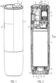
- FIG. 1 An aerosol-generating device 1 according to a first embodiment of the invention is shown in an upright orientation in Fig. 1 .
- the aerosol-generating device 1 comprises a housing 2 and a cover element 3 slidably arranged on the housing 2 in the transverse direction 100.
- the housing 2 extends predominantly in a longitudinal height direction 200, and has its comparatively smallest extension in the width direction 300.
- the cover element 3 is shown in the closed position in Figs. 1 and 2 , covering the aperture of a heating chamber 4.
- the heating chamber 4 When the cover element 3 is in an open position, the heating chamber 4 is adapted to receive a rod-shaped aerosol-generating article and heat same by means of a heating element 5.
- the heating element 5 is an inductive coil module, which is adapted to heat a susceptor, which may be part of the rod-shaped aerosol-generating article.
- the heating element 5, control electronics 6 and a battery 7 are arranged in a housing compartment 8 of the housing 2.
- the housing compartment 8 is sealed, to prevent water or dust from entering the housing compartment 8.
- the housing compartment 8 may comprise a button 9, which is overmolded to be sealed.
- the gas inside the housing compartment 8 is heated and expands rapidly. This would increase the pressure inside the sealed housing compartment 8 and this pressure would also act against the inside of the button 9, altering the appearance or user activation experience of the button 9.
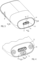
- a venting means 10 is provided in the lower region of the aerosol-generating device 1.
- the venting means 10 is provided next to an electrical connector opening 11.
- the venting means 10 is at least partially arranged in a bottom plate 12 of the housing compartment 8.
- the bottom plate 12 is connected by means of screws 13, to close the housing compartment 8.
- a cover panel 14 is connected to the bottom plate and covers the screws 13.
- a gap 15 is provided in between the bottom plate 12 and the cover panel 14. The gap 15 enables that gas flows in between the bottom plate 12 and the cover panel 14.
- the bottom plate 12 comprises a protruding side wall 16, as can be seen in Fig. 4 .
- the cover panel 14 is connected by means of adhesive to the protruding side wall 16.
- an electrical connector such as a USB-C connector, is provided in the electrical connector opening 11.
- a channel 17 of the venting means 10 opens to the electrical connector opening 11. The channel 17 allows gas flow through the venting means 10.
- Fig. 4 the cover panel 14 is removed, such that the channel 17 may be fully seen.
- the channel 17 leads to an opening 18 in the bottom plate 12.
- the channel 17 extends in the width direction 300, while the opening 18 extends in the transversal direction 100.
- a recessed area 19 is provided in the bottom plate 12 next to the opening 18 and channel 17 of the venting means 10. This facilitates the production of the bottom plate by means of injection molding and enables the beneficial channel 17 and opening 18 geometry.
- an optional spacer 20 is arranged on the inside of the bottom plate 12.
- the spacer 20 may be elastic.
- the bottom plate 12 comprises protrusions 21, which engage into recesses 22 of the spacer 20.
- the spacer 20 is arranged in between and in contact with both a holder 23 and the bottom plate 12.
- the holder 23 may be part of or connected to a battery holder 24.
- the spacer 20 has a central spacer opening 25 and the holder 23 has a central holder opening 26.
- the spacer opening 25 and the holder opening 26 extend in the transverse direction and are substantially aligned.
- a membrane 27 is arranged, such that the membrane covers the openings 25, 26.
- the membrane 27 may be connected to a carrier substrate 28.
- the carrier substrate 28 may be a double adhesive tape.
- the carrier substrate 28 may connect the membrane 27 to the holder 23.
- the carrier substrate 28 has a central opening 29, which is substantially aligned with the openings 25 and 26 of the spacer 20 and holder 23.
- the membrane 27 allows flow of gas, but prevents flow of liquid.
- a second embodiment of the aerosol-generating device 1 is shown.
- the bottom plate 12, which corresponds to the bottom plate 12 of the first embodiment, is removed.
- a venting means 30 is arranged in between a recess 31 for the head 32 of the screw 13 and the electrical connector opening 11.
- the venting means 30 comprises a first channel 33 leading to the electrical connector opening 11.
- the venting means 30 comprises a second channel 34 leading to the screw recess 31.
- air from the inside of the housing compartment 8 may flow through the channels 33, 34 to the electrical connector opening 11 and the screw recess 31 and subsequently to the outside.
- the venting means 30 comprises a membrane 35 which is permeable to gas but not to liquids.
- the membrane 35 is arranged on a carrier substrate 36, which may be in the form of double adhesive tape connecting the membrane 35 to the bottom plate 12.
- the membrane 35 is arranged on the outer side of the bottom plate 12, while in the first embodiment the membrane is arranged on the inner side of the button plate 12.
- the bottom plate 12 of the second embodiment is shown in Fig. 9 in isolation.
- a recess 37 for receiving the membrane 35 and carrier substrate 36 is provided.
- the membrane 35 covers an opening 38, which is centrally provided in the recess 37.
- an aerosol-generating rod is inserted into the heating chamber 4 and heated therein.
- the gas inside the housing compartment 8 of the aerosol-generating device 1 is heated, and thus, through heat expansion of the gas, the pressure increases.
- the venting means 10 or 30 is provided, gas will flow through the membrane 35 and channel 17 in the first embodiment, or membrane 35 and channels 33 and 34 in the second embodiment, and then to the outside.
- gas may flow in and out of the housing compartment 8.
- the channels 17, 33, 34 may be in the form of recesses in the bottom plate 12, forming a tubular channel when being closed by means of the cover panel 14.
- the cover panel is arranged in a distance from the venting membrane, such that a gap is provided in between the cover panel 14 and the venting means 10, 30.
- the venting means 10 may be located in the middle along the transverse direction 100 of the aerosol-generating device 1.
- the opening 18, 28 in the bottom plate 12 may be in the form of a through-hole.
- the gap 15 in between the bottom plate 12 and the cover panel 14 has a height which anticipates the potential deformation of the membrane 35 due to pressure.
- the venting air in the screw recess 31 may escape to the outside along a flow path in between the cover panel 14 and the side wall 16 of the bottom plate 12.
Landscapes
- Containers And Packaging Bodies Having A Special Means To Remove Contents (AREA)
- Nozzles (AREA)
- Catching Or Destruction (AREA)
- Thermotherapy And Cooling Therapy Devices (AREA)
Description
- The present invention relates to an aerosol-generating device with a sealed housing compartment. The present invention also relates to a method for operating an aerosol-generating system and a use of a venting membrane in an aerosol-generating device.
- One type of aerosol-generating system is an electrically operated smoking system. Known handheld electrically operated smoking systems typically comprise an aerosol-generating device comprising a battery, control electronics and an electric heater for heating an aerosol-generating article designed specifically for use with the aerosol-generating device. In some examples, the aerosol-generating article comprises an aerosol-forming substrate, such as a tobacco rod or a tobacco plug, and the heater contained within the aerosol-generating device is inserted into or located around the aerosol-forming substrate when the aerosol-generating article is inserted into the aerosol-generating device. In an alternative electrically operated smoking system, the aerosol-generating article may comprise a capsule containing an aerosol-forming substrate, such as loose tobacco.
- From
US 2020/154789 A1 , an aerosol delivery device that utilizes electrically generated heat to produce aerosol is known. A light window of the aerosol delivery device is covered with a selectively permeable venting material. - According to a first aspect of the invention, there is provided an aerosol-generating device, comprising a heating chamber adapted to receive an aerosol-generating article, a heating element, a sealed housing compartment, and a venting means adapted to allow gas flow from the sealed housing compartment to the outside of the aerosol-generating device to compensate for heat expansion of gas inside the housing compartment due to heating operation of the heating element.
- The transverse direction of the aerosol-generating device may be perpendicular to a longitudinal direction of the aerosol-generating device. The longitudinal direction may be the main extension direction of the aerosol-generating device, namely the direction in which the aerosol-generating device has its greatest length. In an upright orientation of the aerosol-generating device, the longitudinal direction is the height direction and the transversal direction may be a horizontal direction. The transversal direction may be perpendicular to a width direction of the aerosol-generating device. Any indications in the following regarding "upper" and "lower" are with respect to the longitudinal direction being the height direction.
- An aerosol-generating article may be inserted in the heating chamber of the aerosol-generating device in the longitudinal direction, such that the aerosol-generating article is at least partially arranged in a heating chamber. When the aerosol-generating article abuts against a stop element or end surface of the heating chamber, a mouth-end portion of the aerosol-generating article may protrude from the heating chamber in the longitudinal direction.
- The housing compartment is sealed to prevent the ingress of dust or ingress of dust and water. The housing compartment may comprise a bottom plate. The bottom plate may sealingly close the lower side of the housing compartment. At least one of the heating element, control electronics and a battery are arranged in the housing compartment.
- The heating element is provided in the sealed housing compartment.
- The heating element may be an electrical resistance heating element, or an inductive heating element, such as an inductor, for example a coil. Control electronics may be provided, which are adapted to control the heating element to swiftly heat the aerosol-generating article in the heating chamber. The heating element and the control electronics of the device may be adapted, such that the temperature of the heating element is in between 70 degrees Celsius and 130 degrees Celsius, or in between 80 degrees Celsius and 120 degrees Celsius, or in between 80 degrees Celsius and 100 degrees Celsius. The heating element and the control electronics may be adapted, such that the heating time for heating the heating element from ambient temperature to at least 80 degrees Celsius is less than 5 seconds or less than 3 seconds.
- The heating element and the control electronics of the device may be adapted, such that the aerosol-generating article is heated to a temperature between 70 degrees Celsius and 130 degrees Celsius, or in between 80 degrees Celsius and 120 degrees Celsius, or in between 80 degrees Celsius and 100 degrees Celsius. The heating element and the control electronics may be adapted, such that the heating time for heating the aerosol-generating article from ambient temperature to at least 80 degrees Celsius is less than 5 seconds or less than 3 seconds.
- The heating element and the control electronics of the device may be adapted, such that the aerosol-generating article is heated to a temperature between 250 degrees Celsius and 400 degrees Celsius, or in between 300 degrees Celsius and 350 degrees Celsius. The heating element and the control electronics may be adapted, such that the heating time for the aerosol-generating article from ambient temperature to at least 300 degrees Celsius is less than 60 seconds or less than 30 seconds.
- The heating element and the control electronics may be adapted to heat in several consecutive heating cycles during the consumption of one aerosol-generating article, with a temperature variation in the heating element of at least 10 degrees Celsius, or at least 20 degrees Celsius.
- Due to the temperature change of gas in the housing compartment, pressure may build up in the housing compartment. The venting means allows gas to flow from the sealed housing compartment to the outside to prevent excess pressures in the sealed housing compartment. The venting means may be adapted to allow gas to flow from the outside into the sealed housing compartment, to compensate negative, below-ambient pressures during cooling or in the low temperature phases during aerosol generation.
- The venting means may be permeable for gases and impermeable for water. Thus, the aerosol-generating device may be waterproof.
- The venting means may have a water entry pressure of at least 5 Kilopascal, preferably of at least 10 Kilopascal, in particular of about 12 Kilopascal. This enables, that the device is increasingly waterproof.
- The venting means may have an airflow capacity of 3000 to 7000 milliliter per square centimeter and minute at 7 Kilopascal, preferably of 5000 to 5200 milliliter per square centimeter and minute at 7 Kilopascal. The airflow capacity allows for rapidly compensating for temperature changes in the aerosol-generating device.
- The venting means may be operational in a temperature range of - 40 degrees Celsius to 150 degrees Celsius. In another embodiment, the venting means may be operational in a temperature range of -20 degrees Celsius to 90 degrees Celsius. The venting means may have the aforementioned airflow capacity over this entire temperature range. The venting means may have the aforementioned water entry pressure over this entire temperature range.
- The venting means may comprise a membrane. The membrane may be adapted such that gas may flow through the membrane. The area of the membrane may define the possible gas flow. The membrane may be adapted such that liquids, in particular water, may not flow through the membrane.
- The venting means may comprise a membrane with expanded Polytetrafluoroethylene. This allows a preferable implementation of a waterproof, gas-permeable membrane.
- The venting means may comprise expanded Polytetrafluoroethylene applied on a backing layer. The backing layer may be both gas and water permeable, and may provide structural stability.
- The venting means may comprise a hydrophobic and oleophobic membrane. This enables to protect the inside of the sealed housing compartment from polar liquids, such as water, and non-polar liquids, such as oil.
- The venting means may comprise an inert and UV-resistant membrane. Thus, the durability of the membrane may be improved when the membrane comes in contact with potentially reactive substances from the environment.
- The membrane may be connected to a carrier substrate having a central opening with a size of at least 0.5 square millimeters, of at least 1 square millimeter or of at least 2 square millimeters. The carrier substrate may be of a flat rectangular form with a central opening. Alternatively, the carrier substrate may be of a flat circular form with a central opening.
- The carrier substrate may improve the sealing properties of the membrane and the fluid-tight connection of the membrane to the sealed housing compartment. The size of the opening determines the potential gas flow at a given relative pressure on opposite sides of the membrane.
- The carrier substrate may be a double-sided adhesive layer, connecting the membrane to the housing compartment. Thus, the double function of sealing and connecting is provided.
- The membrane may have a thickness of 0.05 to 0.5 millimeters, preferably of 0.1 to 0.2 millimeters, in particular about 0.15 millimeters. This thickness range provides a structurally stable, yet sufficiently permeable membrane.
- The membrane is overlappingly arranged on an opening of the housing compartment. This allows sealing the opening of the housing compartment, while still allowing venting through the membrane. The opening may be a through-hole in a wall of the housing compartment.
- The venting means may comprise an opening in the housing compartment and a channel extending into a housing compartment wall. The housing compartment wall may be formed by a bottom plate. The extension direction of the channel may be in a different direction than the opening direction of the housing opening. Thus, the venting means, and in particular a membrane of the venting means, may be protected from contact with outside objects. The fluid flow may be improved, since gas flow may be less restricted by this geometry than liquid flow. The channel and opening geometry may be particularly preferable regarding polar liquids, such as water, preventing same from reaching the membrane due to their surface tension. The extension direction of the channel may be at an angle of at least 45 degrees, preferably at least 60 degrees, and in particular perpendicular to the opening direction of the housing opening.
- The housing opening may have a cross-sectional area greater than the cross-sectional area of the channel. Thus, a sufficiently high flow through the opening in the housing may be obtained, despite a membrane being arranged therein.
- The channel may have a cross-sectional area of in between 0.5 square millimeters and 2 square millimeters. This provides for a sufficient gas flow, yet making it difficult for liquids to enter in the channel.
- The channel may be a recess extending into a housing compartment wall. Thus, gas may flow out of the channel at any point of its length extension. Alternatively, the channel may be a closed channel with walls on all sides along the flow direction.
- The channel may connect the venting means to a recessed area in the housing compartment wall. The recessed area may have a larger opening towards the outside than the channel, facilitating gas outflow.
- The bottom plate may be fixed by means of screws. Arranging the venting means close to a screw enables that it is provided in a region of the aerosol-generating device, which is unlikely to deform during normal handling, in particular due to the tensioning force of the screw. Thus, it is less likely that involuntary relative movement of parts of the aerosol-generating device, block channels or openings of the venting means.
- A screw head may be arranged in the recessed area. Thus, the recess required for the screw head accommodation, may provide a double function for venting gas flow.
- An electrical connector may be arranged in the recessed area. Thus, an electrical connector opening may be used for venting.
- A cover panel may be arranged outside of the venting means, wherein a gap is provided in between the cover panel and the venting means, such that the venting means is arranged in a distance of 0.3 millimeters to 1 millimeter from the cover panel. Thus, venting gas flow in between the cover panel and venting means is possible. Furthermore, the venting means may be protected from mechanical damage.
- The bottom plate may comprise a protruding side wall in the transversal direction. The cover panel may be fixed to the inside of the protruding side wall. The cover panel may be clipped in or fixed by means of adhesive to the bottom plate.
- The sealed housing compartment may comprise electronic components. The sealed housing compartment may protect the electronic components from damage by liquids.
- The sealed housing compartment comprises a button adapted to interact with control electronics in the sealed housing compartment, wherein movement of the button alters the inside volume of the sealed housing compartment. Since the housing compartment is sealed, a change in temperature changes the pressure inside the housing compartment, which may alter the position or responsive force of the button. The venting means enables that the pressure inside the sealed housing compartment is not significantly altered even during heating by means of the heating element, and ensures that the button may be operated with the same haptic properties at any time. The button may be overmolded with elastic material to enable sealing of the housing compartment. The button may be attached with double adhesive tape to enable sealing of the housing compartment.
- The venting means may comprise a membrane, which is arranged on the outer side of a housing compartment wall, in particular in the form of a bottom plate.
- The venting means may comprise a membrane, which is arranged on the inner side of a housing compartment wall, in particular in the form of a bottom plate.
- The membrane may be arranged in a recess in the housing compartment wall. This allows for protection of the membrane. The membrane may deform due to pressure.
- According to a second aspect of the present invention there is provided an aerosol-generating system comprising an aerosol-generating device according to the first aspect of the present invention in accordance with any of the embodiments described herein. The aerosol-generating system also comprises an aerosol-generating article comprising an aerosol-forming substrate. As used herein, the term "aerosol-generating article" refers to an article comprising an aerosol-forming substrate that, when heated, releases volatile compounds that can form an aerosol.
- The aerosol-forming substrate may comprise a plug of tobacco. The tobacco plug may comprise one or more of: powder, granules, pellets, shreds, spaghettis, strips or sheets containing one or more of: tobacco leaf, fragments of tobacco ribs, reconstituted tobacco, homogenised tobacco, extruded tobacco and expanded tobacco. Optionally, the tobacco plug may contain additional tobacco or non-tobacco volatile flavour compounds, to be released upon heating of the tobacco plug. Optionally, the tobacco plug may also contain capsules that, for example, include the additional tobacco or non-tobacco volatile flavour compounds. Such capsules may melt during heating of the tobacco plug. Alternatively, or in addition, such capsules may be crushed prior to, during, or after heating of the tobacco plug.
- Where the tobacco plug comprises homogenised tobacco material, the homogenised tobacco material may be formed by agglomerating particulate tobacco. The homogenised tobacco material may be in the form of a sheet. The homogenised tobacco material may have an aerosolformer content of greater than 5 percent on a dry weight basis. The homogenised tobacco material may alternatively have an aerosol former content of between 5 percent and 30 percent by weight on a dry weight basis. Sheets of homogenised tobacco material may be formed by agglomerating particulate tobacco obtained by grinding or otherwise comminuting one or both of tobacco leaf lamina and tobacco leaf stems; alternatively, or in addition, sheets of homogenised tobacco material may comprise one or more of tobacco dust, tobacco fines and other particulate tobacco byproducts formed during, for example, the treating, handling and shipping of tobacco. Sheets of homogenised tobacco material may comprise one or more intrinsic binders, that is tobacco endogenous binders, one or more extrinsic binders, that is tobacco exogenous binders, or a combination thereof to help agglomerate the particulate tobacco. Alternatively, or in addition, sheets of homogenised tobacco material may comprise other additives including, but not limited to, tobacco and non-tobacco fibres, aerosol-formers, humectants, plasticisers, flavourants, fillers, aqueous and non-aqueous solvents and combinations thereof. Sheets of homogenised tobacco material are preferably formed by a casting process of the type generally comprising casting a slurry comprising particulate tobacco and one or more binders onto a conveyor belt or other support surface, drying the cast slurry to form a sheet of homogenised tobacco material and removing the sheet of homogenised tobacco material from the support surface.
- The aerosol-generating article may have a total length of between approximately 30 millimetres and approximately 100 millimetres. The aerosol-generating article may have an external diameter of between approximately 5 millimetres and approximately 13 millimetres.
- The aerosol-generating article may comprise a mouthpiece positioned downstream of the tobacco plug. The mouthpiece may be located at a downstream end of the aerosol-generating article. The mouthpiece may be a cellulose acetate filter plug. Preferably, the mouthpiece is approximately 7 millimetres in length, but can have a length of between approximately 5 millimetres to approximately 10 millimetres.
- The tobacco plug may have a length of approximately 10 millimetres. The tobacco plug may have a length of approximately 12 millimetres.
- The diameter of the tobacco plug may be between approximately 5 millimetres and approximately 12 millimetres.
- In a preferred embodiment, the aerosol-generating article has a total length of between approximately 40 millimetres and approximately 50 millimetres. Preferably, the aerosol- generating article has a total length of approximately 45 millimetres. Preferably, the aerosol- generating article has an external diameter of approximately 7.2 millimetres.
- According to a third aspect of the present invention there is provided a method for operating an aerosol-generating system, comprising the steps of inserting an aerosol-generating article in a heating chamber of an aerosol-generating device, heating the aerosol-generating article by means of a heating element to generate aerosol, allowing heated gas to flow from a sealed housing compartment of the aerosol-generating device to the outside through a venting means. The heating element is provided inside a sealed housing compartment of the aerosol-generating device. Thus, despite the heating, the pressure inside the sealed housing compartment is not significantly altered. The inside of the sealed housing compartment may be at substantially ambient pressure, despite the heating.
- Water may be prevented to flow from the outside through the venting means into the housing compartment. Thus, control electronics inside the sealed housing compartment are protected.
- The venting gas may flow through a recess for a screw head. Thus, the volume in between the walls of the screw head recess and the screw head may be used as a venting channel or outlet.
- The venting gas may flow through an electrical connector opening. Thus, the electrical connector opening may be used as a venting outlet.
- The venting gas may flow under a cover panel. Thus, the venting means may be protected. The flow of heating gas may be distributed to one or several outlet locations in or at the cover panel.
- According to a fourth aspect of the present invention there is provided a use of a venting membrane in an aerosol-generating device comprising a heating element inside a sealed housing compartment of the aerosol-generating device to compensate heat expansion of gas due to heat produced in a heating chamber receiving an aerosol-generating article. Thus, it is possible to prevent pressure build-up in the aerosol-generating device due to heat expansion of the gas therein.
- The device according to the first aspect of the invention may be used according to the method of the third aspect of the invention in any of its embodiments. The method according to the third aspect of the invention may be performed by using the device according to the first aspect of the invention in any of its embodiments or the system according to the second aspect of the invention in any of its embodiments. The use of the venting membrane according to the fourth aspect of the invention may be performed with the device according to the first aspect of the invention in any of its embodiments and by using method steps from the method according to the third aspect of the invention in any of its embodiments.
- Examples will now be further described with reference to the figures.
-
Fig. 1 shows a perspective view of an aerosol-generating device. -
Fig. 2 shows a cross-section through the aerosol-generating device ofFig. 1 . -
Fig. 3 shows a perspective view of the aerosol-generating device ofFig. 1 from below. -
Fig. 4 shows a partial perspective view of the aerosol-generating device ofFig. 1 from below without the cover panel. -
Fig. 5 shows a partial cross-sectional view of the lower region of the aerosol-generating device ofFig. 1 . -
Fig. 6 shows a partial cross-sectional view of the lower region of the aerosol-generating device ofFig. 1 with an inner holder removed. -
Fig. 7 shows a partial cross-sectional view of the lower region of the aerosol-generating device ofFig. 1 . -
Fig. 8 shows a partial perspective view of the aerosol-generating device according to a second embodiment of the invention from below without the cover panel. -
Fig. 9 shows a perspective view of the bottom plate in the second embodiment. - An aerosol-generating device 1 according to a first embodiment of the invention is shown in an upright orientation in
Fig. 1 . The aerosol-generating device 1 comprises ahousing 2 and acover element 3 slidably arranged on thehousing 2 in thetransverse direction 100. Thehousing 2 extends predominantly in alongitudinal height direction 200, and has its comparatively smallest extension in thewidth direction 300. Thecover element 3 is shown in the closed position inFigs. 1 and 2 , covering the aperture of a heating chamber 4. - When the
cover element 3 is in an open position, the heating chamber 4 is adapted to receive a rod-shaped aerosol-generating article and heat same by means of aheating element 5. Theheating element 5 is an inductive coil module, which is adapted to heat a susceptor, which may be part of the rod-shaped aerosol-generating article. Theheating element 5,control electronics 6 and a battery 7 are arranged in ahousing compartment 8 of thehousing 2. - The
housing compartment 8 is sealed, to prevent water or dust from entering thehousing compartment 8. Thehousing compartment 8 may comprise a button 9, which is overmolded to be sealed. - When the aerosol-generating article is heated, aerosol is generated, which may be consumed in a similar manner as a cigarette, with the mouth end of the rod-shaped article protruding from the heating chamber. For a beneficial consumer experience, a sufficient and swift aerosol delivery is desired. This requires a sufficient and swift heating of the aerosol-generating article. Thus, heating of the aerosol-generating article is performed at comparatively high power. This means, that not only the aerosol-generating article but also the
heating element 5 and thecontrol electronics 6 and the battery 7 will generate heat and heat the gas, namely air, inside thehousing compartment 8. - During aerosol-generation, the gas inside the
housing compartment 8 is heated and expands rapidly. This would increase the pressure inside the sealedhousing compartment 8 and this pressure would also act against the inside of the button 9, altering the appearance or user activation experience of the button 9. - To avoid such a pressure increase inside the
housing compartment 8, a venting means 10 is provided in the lower region of the aerosol-generating device 1. The venting means 10 is provided next to anelectrical connector opening 11. - The venting means 10 is at least partially arranged in a
bottom plate 12 of thehousing compartment 8. Thebottom plate 12 is connected by means ofscrews 13, to close thehousing compartment 8. Acover panel 14 is connected to the bottom plate and covers thescrews 13. Agap 15 is provided in between thebottom plate 12 and thecover panel 14. Thegap 15 enables that gas flows in between thebottom plate 12 and thecover panel 14. Thebottom plate 12 comprises a protrudingside wall 16, as can be seen inFig. 4 . Thecover panel 14 is connected by means of adhesive to the protrudingside wall 16. - In
Fig. 3 , an electrical connector, such as a USB-C connector, is provided in theelectrical connector opening 11. Achannel 17 of the venting means 10 opens to theelectrical connector opening 11. Thechannel 17 allows gas flow through the venting means 10. - In
Fig. 4 , thecover panel 14 is removed, such that thechannel 17 may be fully seen. Thechannel 17 leads to anopening 18 in thebottom plate 12. - The
channel 17 extends in thewidth direction 300, while theopening 18 extends in thetransversal direction 100. To enable a constant wall thickness of thebottom plate 12, a recessedarea 19 is provided in thebottom plate 12 next to theopening 18 andchannel 17 of the venting means 10. This facilitates the production of the bottom plate by means of injection molding and enables thebeneficial channel 17 andopening 18 geometry. - As shown in
Fig. 5 , anoptional spacer 20 is arranged on the inside of thebottom plate 12. Thespacer 20 may be elastic. Thebottom plate 12 comprisesprotrusions 21, which engage intorecesses 22 of thespacer 20. Thespacer 20 is arranged in between and in contact with both aholder 23 and thebottom plate 12. In particular, theholder 23 may be part of or connected to abattery holder 24. Thespacer 20 has acentral spacer opening 25 and theholder 23 has a central holder opening 26. Thespacer opening 25 and the holder opening 26 extend in the transverse direction and are substantially aligned. In between theholder 23 and thespacer 20, amembrane 27 is arranged, such that the membrane covers theopenings 25, 26. Themembrane 27 may be connected to acarrier substrate 28. Thecarrier substrate 28 may be a double adhesive tape. Thecarrier substrate 28 may connect themembrane 27 to theholder 23. Thecarrier substrate 28 has acentral opening 29, which is substantially aligned with theopenings 25 and 26 of thespacer 20 andholder 23. Themembrane 27 allows flow of gas, but prevents flow of liquid. - In
Fig. 8 , a second embodiment of the aerosol-generating device 1 according to the invention is shown. For the purpose of illustration, thebottom plate 12, which corresponds to thebottom plate 12 of the first embodiment, is removed. A venting means 30 is arranged in between arecess 31 for thehead 32 of thescrew 13 and theelectrical connector opening 11. The venting means 30 comprises afirst channel 33 leading to theelectrical connector opening 11. The venting means 30 comprises asecond channel 34 leading to thescrew recess 31. Thus, during venting, air from the inside of thehousing compartment 8 may flow through thechannels electrical connector opening 11 and thescrew recess 31 and subsequently to the outside. The venting means 30 comprises amembrane 35 which is permeable to gas but not to liquids. Themembrane 35 is arranged on acarrier substrate 36, which may be in the form of double adhesive tape connecting themembrane 35 to thebottom plate 12. In the second embodiment, themembrane 35 is arranged on the outer side of thebottom plate 12, while in the first embodiment the membrane is arranged on the inner side of thebutton plate 12. - The
bottom plate 12 of the second embodiment is shown inFig. 9 in isolation. Arecess 37 for receiving themembrane 35 andcarrier substrate 36 is provided. Themembrane 35 covers anopening 38, which is centrally provided in therecess 37. - In an embodiment of the method according to the invention, an aerosol-generating rod is inserted into the heating chamber 4 and heated therein. The gas inside the
housing compartment 8 of the aerosol-generating device 1 is heated, and thus, through heat expansion of the gas, the pressure increases. Since the venting means 10 or 30 is provided, gas will flow through themembrane 35 andchannel 17 in the first embodiment, ormembrane 35 andchannels housing compartment 8. However, due to the arrangement of thechannels opening membrane - The
channels bottom plate 12, forming a tubular channel when being closed by means of thecover panel 14. Preferably, the cover panel is arranged in a distance from the venting membrane, such that a gap is provided in between thecover panel 14 and the venting means 10, 30. - The venting means 10 may be located in the middle along the
transverse direction 100 of the aerosol-generating device 1. Theopening bottom plate 12 may be in the form of a through-hole. Thegap 15 in between thebottom plate 12 and thecover panel 14 has a height which anticipates the potential deformation of themembrane 35 due to pressure. The venting air in thescrew recess 31 may escape to the outside along a flow path in between thecover panel 14 and theside wall 16 of thebottom plate 12. - For the purpose of the present description and of the appended claims, except where otherwise indicated, all numbers expressing amounts, quantities, percentages, and so forth, are to be understood as being modified in all instances by the term "about". Also, all ranges include the maximum and minimum points disclosed and include any intermediate ranges therein, which may or may not be specifically enumerated herein. In this context, therefore, a number A is understood as A ± 10% of A. Within this context, a number A may be considered to include numerical values that are within general standard error for the measurement of the property that the number A modifies. The number A, in some instances as used in the appended claims, may deviate by the percentages enumerated above provided that the amount by which A deviates does not materially affect the basic and novel characteristic(s) of the claimed invention. Also, all ranges include the maximum and minimum points disclosed and include any intermediate ranges therein, which may or may not be specifically enumerated herein.
Claims (15)
- An aerosol-generating device (1), comprisinga heating chamber (4) adapted to receive an aerosol-generating article,a sealed housing compartment (8),a heating element (5) provided in the sealed housing compartment (8),a venting means (10) adapted to allow gas flow from the sealed housing compartment (8) to the outside of the aerosol-generating device (1) to compensate for heat expansion of gas inside the housing compartment (8) due to heating operation of the heating element (5).
- The aerosol-generating device according to claim 1, wherein the venting means (10) has a water entry pressure of at least 5 Kilopascal, preferably of at least 10 Kilopascal, in particular of about 12 Kilopascal.
- The aerosol-generating device according to claim 1 or 2, wherein the venting means (10) has an airflow capacity of 3000 to 7000 milliliter per square centimeter and minute at 7 Kilopascal, preferably of 5000 to 5200 milliliter per square centimeter and minute at 7 Kilopascal.
- The aerosol-generating device according to any one of the preceding claims, wherein the venting means (10) comprises expanded Polytetrafluoroethylene applied on a backing layer.
- The aerosol-generating device according to any one of the preceding claims, wherein the venting means (10) comprises a membrane (27), wherein the membrane (27) is connected to a carrier substrate (28) having a central opening (29) with a size of at least 0.5 square millimeters, of at least 1 square millimeter or of at least 2 square millimeters.
- The aerosol-generating device according to claim 5, wherein the membrane (27) has a thickness of 0.05 to 0.5 millimeters, preferably of 0.1 to 0.2 millimeters, in particular about 0.15 millimeters.
- The aerosol-generating device according to any one of the preceding claims, wherein the venting means (10) comprises an opening (18) in the housing compartment (8) and a channel (17) extending in a housing compartment wall, wherein the extension direction of the channel (17) is in a different direction than the opening direction of the housing opening (18).
- The aerosol-generating device according to claim 7, wherein the channel (17) is a recess extending in a housing compartment wall.
- The aerosol-generating device according to claim 7 or 8, wherein the channel (17) connects the venting means (10) to a recessed area (19) in the housing compartment wall.
- The aerosol-generating device according to claim 9, wherein a screw head is arranged in the recessed area (19) and/or wherein an electrical connector is arranged in the recessed area (19).
- The aerosol-generating device according to any one of the preceding claims, wherein a cover panel (14) is arranged outside of the venting means (10), wherein a gap (15) is provided in between the cover panel (14) and the venting means (10), wherein preferably the venting means (10) is arranged in a distance of 0.3 millimeters to 1 millimeter to the cover panel (14).
- The aerosol-generating device according to any one of the preceding claims, wherein the sealed housing compartment (8) comprises a button (9) adapted to interact with control electronics in the sealed housing compartment (8), wherein movement of the button (9) alters the inside volume of the sealed housing compartment (8).
- A method for operating an aerosol-generating system, comprising the steps of:- inserting an aerosol-generating article in a heating chamber (4) of an aerosol-generating device (1),- heating the aerosol-generating article by means of a heating element (5) to generate aerosol, wherein the heating element (5) is provided in a sealed housing compartment (8) of the aerosol-generating device (1) and- allowing heated gas to flow from the sealed housing compartment (8) to the outside through a venting means (10).
- Use of a venting membrane (27) in an aerosol-generating device (1) comprising a heating element (5) inside a sealed housing compartment (8) of the aerosol-generating device (1) to compensate heat expansion of gas due to heat produced in a heating chamber (4) receiving an aerosol-generating article.
- An aerosol-generating system, comprisingan aerosol-generating device (1) according to any one of claims 1 to 12, andan aerosol-generating article comprising an aerosol-generating substrate.
Priority Applications (1)
| Application Number | Priority Date | Filing Date | Title |
|---|---|---|---|
| EP25152553.1A EP4520204A3 (en) | 2021-03-19 | 2022-03-18 | Aerosol-generating device with venting means |
Applications Claiming Priority (2)
| Application Number | Priority Date | Filing Date | Title |
|---|---|---|---|
| EP21163745 | 2021-03-19 | ||
| PCT/EP2022/057226 WO2022195101A1 (en) | 2021-03-19 | 2022-03-18 | Aerosol-generating device with venting means |
Related Child Applications (2)
| Application Number | Title | Priority Date | Filing Date |
|---|---|---|---|
| EP25152553.1A Division EP4520204A3 (en) | 2021-03-19 | 2022-03-18 | Aerosol-generating device with venting means |
| EP25152553.1A Division-Into EP4520204A3 (en) | 2021-03-19 | 2022-03-18 | Aerosol-generating device with venting means |
Publications (2)
| Publication Number | Publication Date |
|---|---|
| EP4307941A1 EP4307941A1 (en) | 2024-01-24 |
| EP4307941B1 true EP4307941B1 (en) | 2025-05-07 |
Family
ID=75111514
Family Applications (2)
| Application Number | Title | Priority Date | Filing Date |
|---|---|---|---|
| EP25152553.1A Pending EP4520204A3 (en) | 2021-03-19 | 2022-03-18 | Aerosol-generating device with venting means |
| EP22716389.6A Active EP4307941B1 (en) | 2021-03-19 | 2022-03-18 | Aerosol-generating device with venting means |
Family Applications Before (1)
| Application Number | Title | Priority Date | Filing Date |
|---|---|---|---|
| EP25152553.1A Pending EP4520204A3 (en) | 2021-03-19 | 2022-03-18 | Aerosol-generating device with venting means |
Country Status (9)
| Country | Link |
|---|---|
| US (1) | US20240148071A1 (en) |
| EP (2) | EP4520204A3 (en) |
| JP (1) | JP2024510643A (en) |
| KR (1) | KR20230160313A (en) |
| CN (1) | CN116981370A (en) |
| BR (1) | BR112023018098A2 (en) |
| IL (1) | IL305874A (en) |
| PL (1) | PL4307941T3 (en) |
| WO (1) | WO2022195101A1 (en) |
Families Citing this family (2)
| Publication number | Priority date | Publication date | Assignee | Title |
|---|---|---|---|---|
| CN120021797A (en) * | 2023-11-21 | 2025-05-23 | 尼科创业贸易有限公司 | Aerosol supply device |
| WO2025109025A1 (en) * | 2023-11-21 | 2025-05-30 | Nicoventures Trading Limited | Aerosol provision device |
Family Cites Families (3)
| Publication number | Priority date | Publication date | Assignee | Title |
|---|---|---|---|---|
| US11178910B2 (en) * | 2017-05-11 | 2021-11-23 | Kt&G Corporation | Vaporizer and aerosol generation device including same |
| US11588287B2 (en) * | 2018-10-12 | 2023-02-21 | Rai Strategic Holdings, Inc. | Aerosol delivery device with improved connectivity, airflow, and aerosol paths |
| US11156766B2 (en) * | 2018-11-19 | 2021-10-26 | Rai Strategic Holdings, Inc. | Aerosol delivery device |
-
2022
- 2022-03-18 PL PL22716389.6T patent/PL4307941T3/en unknown
- 2022-03-18 EP EP25152553.1A patent/EP4520204A3/en active Pending
- 2022-03-18 EP EP22716389.6A patent/EP4307941B1/en active Active
- 2022-03-18 US US18/550,877 patent/US20240148071A1/en active Pending
- 2022-03-18 KR KR1020237035726A patent/KR20230160313A/en active Pending
- 2022-03-18 WO PCT/EP2022/057226 patent/WO2022195101A1/en not_active Ceased
- 2022-03-18 JP JP2023557196A patent/JP2024510643A/en active Pending
- 2022-03-18 CN CN202280020787.0A patent/CN116981370A/en active Pending
- 2022-03-18 IL IL305874A patent/IL305874A/en unknown
- 2022-03-18 BR BR112023018098A patent/BR112023018098A2/en unknown
Also Published As
| Publication number | Publication date |
|---|---|
| EP4520204A3 (en) | 2025-06-18 |
| EP4520204A2 (en) | 2025-03-12 |
| WO2022195101A1 (en) | 2022-09-22 |
| KR20230160313A (en) | 2023-11-23 |
| EP4307941A1 (en) | 2024-01-24 |
| IL305874A (en) | 2023-11-01 |
| PL4307941T3 (en) | 2025-08-04 |
| BR112023018098A2 (en) | 2023-10-31 |
| CN116981370A (en) | 2023-10-31 |
| JP2024510643A (en) | 2024-03-08 |
| US20240148071A1 (en) | 2024-05-09 |
Similar Documents
| Publication | Publication Date | Title |
|---|---|---|
| US20250120433A1 (en) | Aerosol-generating system with improved air flow control | |
| AU2015286578B2 (en) | Aerosol-generating system comprising cartridge detection | |
| EP4307941B1 (en) | Aerosol-generating device with venting means | |
| US12439968B2 (en) | Housing and flavor aspirator provided with same | |
| EP3179871B1 (en) | Aerosol-generating system comprising multi-purpose computing device | |
| CA2951396A1 (en) | Aerosol-generating system comprising a removable heater | |
| EP4316203B1 (en) | Heater assembly having a sealed airflow pathway | |
| RU2854947C2 (en) | Aerosol-generating device, use of ventilation membrane in aerosol-generating device, aerosol-generating system, and method for using such system | |
| EP4094599B1 (en) | Suction device | |
| US20240423293A1 (en) | Method of testing air leakage | |
| JP2024512951A (en) | Heater assembly with fasteners | |
| EP3995014A1 (en) | Heating assembly and flavor inhaler | |
| KR20230080429A (en) | Aerosol generating device with ejection mechanism | |
| US20250000152A1 (en) | Aerosol generating device with sealed internal airflow channel | |
| RU2839352C2 (en) | Aerosol generating device with sealed inner air flow channel | |
| WO2024040478A1 (en) | Heater assembly having separated sealing elements | |
| WO2021111308A1 (en) | Shisha device configured to perforate a cartridge | |
| HK1231332B (en) | Aerosol-generating system comprising cartridge detection |
Legal Events
| Date | Code | Title | Description |
|---|---|---|---|
| STAA | Information on the status of an ep patent application or granted ep patent |
Free format text: STATUS: UNKNOWN |
|
| STAA | Information on the status of an ep patent application or granted ep patent |
Free format text: STATUS: THE INTERNATIONAL PUBLICATION HAS BEEN MADE |
|
| PUAI | Public reference made under article 153(3) epc to a published international application that has entered the european phase |
Free format text: ORIGINAL CODE: 0009012 |
|
| STAA | Information on the status of an ep patent application or granted ep patent |
Free format text: STATUS: REQUEST FOR EXAMINATION WAS MADE |
|
| 17P | Request for examination filed |
Effective date: 20230912 |
|
| AK | Designated contracting states |
Kind code of ref document: A1 Designated state(s): AL AT BE BG CH CY CZ DE DK EE ES FI FR GB GR HR HU IE IS IT LI LT LU LV MC MK MT NL NO PL PT RO RS SE SI SK SM TR |
|
| DAV | Request for validation of the european patent (deleted) | ||
| DAX | Request for extension of the european patent (deleted) | ||
| GRAP | Despatch of communication of intention to grant a patent |
Free format text: ORIGINAL CODE: EPIDOSNIGR1 |
|
| STAA | Information on the status of an ep patent application or granted ep patent |
Free format text: STATUS: GRANT OF PATENT IS INTENDED |
|
| INTG | Intention to grant announced |
Effective date: 20241113 |
|
| GRAS | Grant fee paid |
Free format text: ORIGINAL CODE: EPIDOSNIGR3 |
|
| P01 | Opt-out of the competence of the unified patent court (upc) registered |
Free format text: CASE NUMBER: APP_2513/2025 Effective date: 20250115 |
|
| GRAA | (expected) grant |
Free format text: ORIGINAL CODE: 0009210 |
|
| STAA | Information on the status of an ep patent application or granted ep patent |
Free format text: STATUS: THE PATENT HAS BEEN GRANTED |
|
| AK | Designated contracting states |
Kind code of ref document: B1 Designated state(s): AL AT BE BG CH CY CZ DE DK EE ES FI FR GB GR HR HU IE IS IT LI LT LU LV MC MK MT NL NO PL PT RO RS SE SI SK SM TR |
|
| REG | Reference to a national code |
Ref country code: GB Ref legal event code: FG4D |
|
| REG | Reference to a national code |
Ref country code: CH Ref legal event code: EP |
|
| REG | Reference to a national code |
Ref country code: DE Ref legal event code: R096 Ref document number: 602022014305 Country of ref document: DE |
|
| REG | Reference to a national code |
Ref country code: IE Ref legal event code: FG4D |
|
| REG | Reference to a national code |
Ref country code: NL Ref legal event code: FP |
|
| PG25 | Lapsed in a contracting state [announced via postgrant information from national office to epo] |
Ref country code: FI Free format text: LAPSE BECAUSE OF FAILURE TO SUBMIT A TRANSLATION OF THE DESCRIPTION OR TO PAY THE FEE WITHIN THE PRESCRIBED TIME-LIMIT Effective date: 20250507 Ref country code: PT Free format text: LAPSE BECAUSE OF FAILURE TO SUBMIT A TRANSLATION OF THE DESCRIPTION OR TO PAY THE FEE WITHIN THE PRESCRIBED TIME-LIMIT Effective date: 20250908 Ref country code: ES Free format text: LAPSE BECAUSE OF FAILURE TO SUBMIT A TRANSLATION OF THE DESCRIPTION OR TO PAY THE FEE WITHIN THE PRESCRIBED TIME-LIMIT Effective date: 20250507 |
|
| REG | Reference to a national code |
Ref country code: LT Ref legal event code: MG9D |
|
| PG25 | Lapsed in a contracting state [announced via postgrant information from national office to epo] |
Ref country code: NO Free format text: LAPSE BECAUSE OF FAILURE TO SUBMIT A TRANSLATION OF THE DESCRIPTION OR TO PAY THE FEE WITHIN THE PRESCRIBED TIME-LIMIT Effective date: 20250807 Ref country code: GR Free format text: LAPSE BECAUSE OF FAILURE TO SUBMIT A TRANSLATION OF THE DESCRIPTION OR TO PAY THE FEE WITHIN THE PRESCRIBED TIME-LIMIT Effective date: 20250808 |
|
| REG | Reference to a national code |
Ref country code: AT Ref legal event code: MK05 Ref document number: 1791428 Country of ref document: AT Kind code of ref document: T Effective date: 20250507 |
|
| PG25 | Lapsed in a contracting state [announced via postgrant information from national office to epo] |
Ref country code: BG Free format text: LAPSE BECAUSE OF FAILURE TO SUBMIT A TRANSLATION OF THE DESCRIPTION OR TO PAY THE FEE WITHIN THE PRESCRIBED TIME-LIMIT Effective date: 20250507 |
|
| PG25 | Lapsed in a contracting state [announced via postgrant information from national office to epo] |
Ref country code: HR Free format text: LAPSE BECAUSE OF FAILURE TO SUBMIT A TRANSLATION OF THE DESCRIPTION OR TO PAY THE FEE WITHIN THE PRESCRIBED TIME-LIMIT Effective date: 20250507 |
|
| PG25 | Lapsed in a contracting state [announced via postgrant information from national office to epo] |
Ref country code: AT Free format text: LAPSE BECAUSE OF FAILURE TO SUBMIT A TRANSLATION OF THE DESCRIPTION OR TO PAY THE FEE WITHIN THE PRESCRIBED TIME-LIMIT Effective date: 20250507 |
|
| PG25 | Lapsed in a contracting state [announced via postgrant information from national office to epo] |
Ref country code: RS Free format text: LAPSE BECAUSE OF FAILURE TO SUBMIT A TRANSLATION OF THE DESCRIPTION OR TO PAY THE FEE WITHIN THE PRESCRIBED TIME-LIMIT Effective date: 20250807 |
|
| PG25 | Lapsed in a contracting state [announced via postgrant information from national office to epo] |
Ref country code: IS Free format text: LAPSE BECAUSE OF FAILURE TO SUBMIT A TRANSLATION OF THE DESCRIPTION OR TO PAY THE FEE WITHIN THE PRESCRIBED TIME-LIMIT Effective date: 20250907 |
|
| PG25 | Lapsed in a contracting state [announced via postgrant information from national office to epo] |
Ref country code: LV Free format text: LAPSE BECAUSE OF FAILURE TO SUBMIT A TRANSLATION OF THE DESCRIPTION OR TO PAY THE FEE WITHIN THE PRESCRIBED TIME-LIMIT Effective date: 20250507 |
|
| PG25 | Lapsed in a contracting state [announced via postgrant information from national office to epo] |
Ref country code: DK Free format text: LAPSE BECAUSE OF FAILURE TO SUBMIT A TRANSLATION OF THE DESCRIPTION OR TO PAY THE FEE WITHIN THE PRESCRIBED TIME-LIMIT Effective date: 20250507 Ref country code: SM Free format text: LAPSE BECAUSE OF FAILURE TO SUBMIT A TRANSLATION OF THE DESCRIPTION OR TO PAY THE FEE WITHIN THE PRESCRIBED TIME-LIMIT Effective date: 20250507 |
|
| PG25 | Lapsed in a contracting state [announced via postgrant information from national office to epo] |
Ref country code: CZ Free format text: LAPSE BECAUSE OF FAILURE TO SUBMIT A TRANSLATION OF THE DESCRIPTION OR TO PAY THE FEE WITHIN THE PRESCRIBED TIME-LIMIT Effective date: 20250507 |
|
| PG25 | Lapsed in a contracting state [announced via postgrant information from national office to epo] |
Ref country code: EE Free format text: LAPSE BECAUSE OF FAILURE TO SUBMIT A TRANSLATION OF THE DESCRIPTION OR TO PAY THE FEE WITHIN THE PRESCRIBED TIME-LIMIT Effective date: 20250507 |
|
| PG25 | Lapsed in a contracting state [announced via postgrant information from national office to epo] |
Ref country code: SK Free format text: LAPSE BECAUSE OF FAILURE TO SUBMIT A TRANSLATION OF THE DESCRIPTION OR TO PAY THE FEE WITHIN THE PRESCRIBED TIME-LIMIT Effective date: 20250507 |
|
| PLBI | Opposition filed |
Free format text: ORIGINAL CODE: 0009260 |