EP4307847A1 - Modular data centers - Google Patents
Modular data centers Download PDFInfo
- Publication number
- EP4307847A1 EP4307847A1 EP23185047.0A EP23185047A EP4307847A1 EP 4307847 A1 EP4307847 A1 EP 4307847A1 EP 23185047 A EP23185047 A EP 23185047A EP 4307847 A1 EP4307847 A1 EP 4307847A1
- Authority
- EP
- European Patent Office
- Prior art keywords
- frame
- electrical module
- base electrical
- data center
- modular data
- Prior art date
- Legal status (The legal status is an assumption and is not a legal conclusion. Google has not performed a legal analysis and makes no representation as to the accuracy of the status listed.)
- Pending
Links
- 238000000034 method Methods 0.000 claims description 17
- 230000000007 visual effect Effects 0.000 claims description 4
- 238000005516 engineering process Methods 0.000 abstract description 3
- 230000006870 function Effects 0.000 description 11
- 238000004891 communication Methods 0.000 description 5
- 238000007726 management method Methods 0.000 description 5
- 239000003570 air Substances 0.000 description 4
- 238000012423 maintenance Methods 0.000 description 3
- 238000012545 processing Methods 0.000 description 3
- 230000004075 alteration Effects 0.000 description 2
- 238000010276 construction Methods 0.000 description 2
- 230000006872 improvement Effects 0.000 description 2
- 230000010354 integration Effects 0.000 description 2
- 239000002184 metal Substances 0.000 description 2
- 238000012986 modification Methods 0.000 description 2
- 230000004048 modification Effects 0.000 description 2
- 230000006855 networking Effects 0.000 description 2
- 240000005020 Acaciella glauca Species 0.000 description 1
- HBBGRARXTFLTSG-UHFFFAOYSA-N Lithium ion Chemical compound [Li+] HBBGRARXTFLTSG-UHFFFAOYSA-N 0.000 description 1
- 230000004308 accommodation Effects 0.000 description 1
- 239000012080 ambient air Substances 0.000 description 1
- 239000013065 commercial product Substances 0.000 description 1
- 238000001816 cooling Methods 0.000 description 1
- 230000008878 coupling Effects 0.000 description 1
- 238000010168 coupling process Methods 0.000 description 1
- 238000005859 coupling reaction Methods 0.000 description 1
- 238000013500 data storage Methods 0.000 description 1
- 238000013461 design Methods 0.000 description 1
- 229910001416 lithium ion Inorganic materials 0.000 description 1
- 230000003287 optical effect Effects 0.000 description 1
- 230000002093 peripheral effect Effects 0.000 description 1
- 238000007639 printing Methods 0.000 description 1
- 235000003499 redwood Nutrition 0.000 description 1
- 230000003068 static effect Effects 0.000 description 1
Images






Classifications
-
- H—ELECTRICITY
- H05—ELECTRIC TECHNIQUES NOT OTHERWISE PROVIDED FOR
- H05K—PRINTED CIRCUITS; CASINGS OR CONSTRUCTIONAL DETAILS OF ELECTRIC APPARATUS; MANUFACTURE OF ASSEMBLAGES OF ELECTRICAL COMPONENTS
- H05K7/00—Constructional details common to different types of electric apparatus
- H05K7/14—Mounting supporting structure in casing or on frame or rack
- H05K7/1485—Servers; Data center rooms, e.g. 19-inch computer racks
- H05K7/1488—Cabinets therefor, e.g. chassis or racks or mechanical interfaces between blades and support structures
- H05K7/1492—Cabinets therefor, e.g. chassis or racks or mechanical interfaces between blades and support structures having electrical distribution arrangements, e.g. power supply or data communications
-
- H—ELECTRICITY
- H05—ELECTRIC TECHNIQUES NOT OTHERWISE PROVIDED FOR
- H05K—PRINTED CIRCUITS; CASINGS OR CONSTRUCTIONAL DETAILS OF ELECTRIC APPARATUS; MANUFACTURE OF ASSEMBLAGES OF ELECTRICAL COMPONENTS
- H05K7/00—Constructional details common to different types of electric apparatus
- H05K7/14—Mounting supporting structure in casing or on frame or rack
- H05K7/1485—Servers; Data center rooms, e.g. 19-inch computer racks
- H05K7/1497—Rooms for data centers; Shipping containers therefor
-
- H—ELECTRICITY
- H05—ELECTRIC TECHNIQUES NOT OTHERWISE PROVIDED FOR
- H05K—PRINTED CIRCUITS; CASINGS OR CONSTRUCTIONAL DETAILS OF ELECTRIC APPARATUS; MANUFACTURE OF ASSEMBLAGES OF ELECTRICAL COMPONENTS
- H05K7/00—Constructional details common to different types of electric apparatus
- H05K7/20—Modifications to facilitate cooling, ventilating, or heating
- H05K7/20709—Modifications to facilitate cooling, ventilating, or heating for server racks or cabinets; for data centers, e.g. 19-inch computer racks
- H05K7/20718—Forced ventilation of a gaseous coolant
- H05K7/20736—Forced ventilation of a gaseous coolant within cabinets for removing heat from server blades
Definitions
- aspects of the present disclosure relate generally to data centers, including microdata centers, that contain racks and enclosures used to house data processing, power, networking and telecommunications equipment.
- Equipment enclosures or racks for housing electronic equipment have been used for many years.
- Such racks are used to contain and to arrange the equipment in small wiring closets, microdata centers, small rooms, as well as equipment rooms and large data centers.
- An equipment rack can be an open configuration and can be housed within a rack enclosure, although the enclosure may be included when referring to a rack.
- hangable information technology (“IT”) racks are known in the industry.
- hangable IT racks are assembled onsite, i.e., at the user's final location, and if an electrician is needed to hard-wire the microdata center, the electrician may be forced to address preinstalled IT equipment that is in the way.
- the modular data center comprises a base electrical module including an uninterruptible power supply (“UPS”) bypass switch and a UPS power connector, a first frame coupled to the base electrical module and configured to house a UPS that receives power from the UPS power connector, and a second frame coupled to the base electrical module and configured to house IT equipment that receives power from the base electrical module, the base electrical module being external to the second frame.
- UPS uninterruptible power supply
- the base electrical module further includes a power connection terminal coupled to the bypass switch.
- the modular data center further comprises a UPS rack included in the first frame, the UPS rack configured for mounting the UPS thereto.
- the modular data center further comprises a UPS rack coupled to the first frame.
- the modular data center further comprises an IT equipment rack included in the second frame, the IT equipment rack configured for mounting the IT equipment thereto.
- the modular data center further comprises an IT equipment rack coupled to the second frame.
- the base electrical module further includes a fan module configured to direct air through the IT equipment rack.
- the modular data center further comprises a fan module included in the base electrical module and configured to direct air through the second frame, and a casing coupled to the fan module with a hinge, the casing enclosing the base electrical module, first frame, and second frame when in a closed position.
- the base electrical module is configured to be mounted to a wall.
- the first frame is coupled to the base electrical module with a hinge.
- the second frame is indirectly coupled to the base electrical module.
- the modular data center further comprises a UPS rack included in the first frame and an IT equipment rack included in the second frame.
- the second frame is removably supported by the first frame.
- the second frame is removably clipped to the first frame.
- the modular data center further comprises a casing removably coupleable to the base electrical module, the casing enclosing the base electrical module, first frame, and second frame when coupled to the base electrical module.
- the modular data center further comprises a casing coupled to the base electrical module with a hinge, the casing enclosing the base electrical module, the first frame, and the second frame when in a closed position.
- the modular data center further comprises a power distribution unit having a plurality of outlets mounted on the second frame and configured to provide power from the base electrical module to the IT equipment.
- the base electrical module further includes a patch panel.
- the base electrical module further includes an Internet gateway device.
- the modular data center further comprises a power distribution unit having a plurality of outlets mounted on the first frame.
- the base electrical module further includes a visual indicator of status of the modular data center.
- the modular data center further comprises at least one backup UPS.
- the modular data center further comprises at least one server.
- a method of assembling and installing a modular data center comprises installing a base electrical module on a wall, the base electrical module including an uninterruptible power supply (“UPS”) bypass switch and a UPS power connector, hingedly connecting a first frame to the base electrical module, the first frame configured to house a UPS that receives power from the UPS power connector, and connecting a second frame to the first frame, the second frame configured to house IT equipment that receives power from the base electrical module, the base electrical module being external to the IT equipment rack.
- UPS uninterruptible power supply
- the method further comprises securing a power distribution unit to the second frame.
- the method further comprises securing a backup UPS module to the first frame.
- the method further comprises securing a cover to the base electrical module.
- All-in-one equipment racks may be used in microdata centers for edge application, which are typically deployed in closets or other locations without adequate cooling resources. These applications use racks sealed from the surrounding ambient air for physical security and environment protection.
- the equipment racks require highly varied requirements, including but not limited to environment, serviceability, security, and management.
- enclosures and "racks” are used to describe apparatus designed to support electronic equipment.
- the present disclosure is directed to a modular data center including a base electrical module that is configured to be mounted on a wall.
- the base electrical module includes a compartment into which a power line enters and lands to a terminal block with a connection to a maintenance bypass switch.
- the base electrical module further includes a fan compartment and the ability to run network cables through an optional patch panel.
- the modular data center further includes a removable first frame that is hinged to one end of the base electrical module, e.g., a left edge of the base electrical module, with a separate second frame for IT equipment that attaches to the hinged first rack frame.
- the modular data center further includes a door or cover is connected to the base electrical module, e.g., a right edge of the base electrical module, by hinges but that can also be removably attached with hardware such as bolts, clips, or other forms of fasteners.
- the base electrical module of the modular data center of embodiments of the present disclosure address issues associated with prior base module concepts, including: 1) current wall mount IT racks are extremely difficult to install due to their size and weight since current wall mount IT racks typically embody one large metal box; and 2) current wall mount IT racks are very complicated to configure due to the collection of components often required in that they do not include integrated power terminals/connections, a maintenance bypass switch, filtered fan compartments, and removable racking frame.
- the modular data center 100 addresses these issues by separating and dividing the overall structure into three core modules with integrated technical components.
- the modular data center 100 includes the base electrical module 200, which embodies a metal box having an integrated power connection terminal 270, input and output connectors 275, a maintenance bypass switch 205, and a fan module 220.
- the power connection terminal 270 is illustrated in the close-up view of a portion of the base electrical module in FIG. 17 in which a cover 215 that would normally cover the power connection terminal 270 is shown removed.
- the base electrical module 200 is mounted on the wall by one or more cleats 225, which creates a small space, e.g., one-quarter to one-half inch, between a back of the base electrical module 200 and the wall.
- the base electrical module 200 is configured to provide control and power to IT equipment mounted on an IT equipment rack 415, with the base electrical module 200 being external to the IT equipment rack 415.
- the base electrical module 200 can include a variety of components, including but not limited to a PDU, an additional PDU, one or more hardwire connections, an accommodation or feature for a subsequent module to be attached, one or more power distribution unit connections, a UPS, a management and security module, and a user interface coupled to the management and security module.
- the modular data center 100 further includes a removable IT frame structure 300, 400 and sealed cover 500. As shown and described below, there is a smaller first IT frame structure 300 secured to the base module 200 and a larger second IT frame structure 400 that is supported by the smaller first IT frame structure 300.
- the first IT frame structure 300 is configured to support a UPS 310 (shown in the exploded view of FIG. 14 ) to provide emergency power.
- the first IT frame structure 300 includes a UPS rack 315 including mounting features such as apertures or slots to which a UPS 310 may be attached.
- the UPS rack 315 may be formed integral with the first IT frame structure 300 or a separate element that is secures to the first IT frame structure with fasteners, for example, nuts, bolts, screws, or other fasteners known in the art.
- the second IT frame structure 400 is configured to support IT equipment 410, for example, one or more servers (shown in the exploded view of FIG. 14 ) that receives power from the base electrical module 200.
- the second IT frame structure 400 includes an IT rack 415 including mounting features such as apertures or slots to which IT equipment 410 may be attached.
- the IT rack 415 may be formed integral with the second IT frame structure 400 or a separate element that is secures to the second IT frame structure with fasteners, for example, nuts, bolts, screws, or other fasteners known in the art.
- the second IT frame structure 400 may include one or more power distribution units (PDUs) 405 to provide power connections to the IT equipment 410.
- PDUs power distribution units
- the base electrical module 200 of the modular data center includes several conduit openings, e.g., three conduit openings 230, 235, 240, that are provided on, for example, a top right corner of the base electrical module 200, one (230) for power and two (235, 240) for network cables.
- Power connection runs into a small compartment in the base electrical module 200 in which the terminal block 270 and the bypass switch 205 are located, as well as two sockets 275 for input and output power to the UPS 310 and a power connection 280 for the fan module 220. (See FIG. 17 .)
- the base electrical module 200 also accommodates hinges 245 on the left edge of the base electrical module 200 for the removable frame structures.
- a fan module 220 is provided on the right side of the base electrical module 200 and includes hinges 250 on the right edge of the base electrical module 200 to attach the cover 500. It is to be understood that in various embodiments each of hinges 245, 250 can embody any type of hinge, such as a barrel hinge, lift-off hinge, a corner hinge, a continuous or piano hinge, or a leaf hinge, to name a few.
- the base electrical module 200 further includes a temperature and/or humidity sensor 260 mounted to an internal wall thereof.
- the temperature and/or humidity sensor 260 may also include additional features and functionality, for example, a security system, camera, internet gateway, etc.
- the temperature and/or humidity sensor 260 may be, for example, one of the NetBotz TM rack sensor/monitor modules available from Schneider Electric.
- the first frame 300 is sized to fit a 1U lithium-ion UPS 310 and has four cleats or clips 305 designed to hold a second frame structure 400, for example, a second frame structure sized for 6U of rack space.
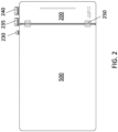
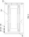
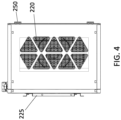
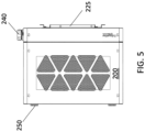
- FIGS. 1-7 are a perspective view, a front elevational view, a rear elevational view, a right elevational view, a left elevational view, a view from the top, and a view from the bottom, respectively, of an exemplary modular data center 100 of embodiments of the present disclosure in a closed configuration.
- the modular data center 100 when fully assembled, the modular data center 100 achieves a compact design.
- the modular data center includes the base electrical module 200 having a UPS bypass switch 205, a power connection terminal 270 coupled to the bypass switch 205, and a UPS power connector 275. (See FIG. 17 .)
- the modular data center 100 further includes a UPS 310 housed by the first IT frame structure 300 coupled to the base electrical module 200 and one or more items of IT equipment 410 housed by the second IT frame structure 400, which is coupled to the base electrical module 200 via the first IT frame structure 300.
- the UPS 310 contains an alternating current (“AC”) power back-up and battery, or reliable direct current (“DC”) power for applications that require direct current.
- the UPS 310 can be connected, disconnected, or replaced by a person skilled in the art of managing IT equipment.
- This UPS 310 can be easily configured and integrated at a domestic or an international facility.
- the UPS 310 can be configured with components manufactured by various entities at partner module integration sites.
- the UPS 310 can be serviced, upgraded, and/or swapped without service interruption of the IT equipment 410.
- the UPS 310 can be used to control power within the modular data center 100 and monitor certain aspects of the modular data center 100 including providing power readings and/or outlet switching.
- the information can be communicated to an operator by an integrated network to a display, which can also function as a management controller.
- FIGS. 8-14 are a perspective view, a front elevational view, a rear elevational view, a right elevational view, a left elevational view, a view from the top, and a view from the bottom, respectively, of the modular data center 100 with the cover 500 in an open position.
- the first IT frame structure 200 and the second IT frame structure 300 are configured achieve a nested position adjacent the base electrical module 200.
- the base electrical module 200 is further shown to have a fan module compartment 255 that houses a fan module 220 to cool electronic components within the IT frame structures 200, 300.
- the cover 500 includes an opening 505 having a fan guard to allow airflow through the modular data center 100 over the UPS 310 and the IT equipment 410 when the cover 500 is in the closed position.
- the cover 500 can include a seal around a peripheral edge to seal the cover 500 when in the closed position shown in FIGS. 1-7 .
- the first IT frame structure 300 is configured to support the UPS 310 to provide emergency power to the IT equipment 410 supported by the second IT frame structure 400.
- the second IT frame structure 400 may include one or more PDUs 405 to provide power connections to the IT equipment 410.
- FIGS. 8 , 9 , 13 , and 14 illustrate the first IT frame structure 300, which is configured to house the UPS 310 that receives power from the UPS power connector 275 associated with the base electrical module 200, and the second IT frame structure 400, which is configured to house IT equipment 410 that receives power from the base electrical module 200.
- the base electrical module 200 is external to the IT equipment rack 415 supported by the second IT frame structure 400.
- the IT equipment rack 415 can be configured to receive one or more pieces of IT equipment 410, e.g., servers.
- the IT equipment rack 415 can be configured to achieve variable U-space distances, e.g., 4-6 U.
- the IT equipment rack 415 can be configured as a 19-inch rack having 21-inch rails.
- the IT equipment 410 when housed by the IT equipment rack 415, can be accessed from the front and back of the IT equipment rack 415 when the IT frame structure 400 is in its open position with respect to the base electrical module 200.
- the IT equipment 410 further can be accessed from the top and/or the bottom of the IT equipment rack 415.
- FIGS. 8 , 9 , and 13 illustrate the first and second IT frame structures 300, 400 and the cover 500 in a fully open position.
- the base electrical module 200 includes the fan compartment 255 that receives the fan module 220.
- the fan module 220 is provided to cool the UPS 310 and the IT equipment 410 housed by the first and second IT frame structures 300, 400, respectively.
- FIG. 9 illustrates the location of the bypass switch 205 within the base electrical module 200.
- a patch panel 265 having CAT 5 cables can be integrated into the base electrical module 200 of the modular data center 100.
- the patch panel 265 may be disposed within compartment 265A (shown in FIG. 15 ) when the modular data center 100 is assembled, as illustrated in FIG. 16 .
- an Internet gateway device can be integrated into the base electrical module 200 of the modular data center 100, for example, as part of the temperature and/or humidity sensor 260 as discussed above, or as a separate module.
- the PDU 405 (or multiple PDUs 405) can be provided in the base electrical module 200 and/or the first IT frame structure 300.
- the base electrical module 200 can include a visual indication 210 (see, e.g., FIG. 3 ) of the status of the modular data center.
- a visual indication 210 see, e.g., FIG. 3
- a set of LEDs green, amber and red LEDs
- the IT equipment and the modules described herein are components that can be configured to be hot-swappable.
- the modular data center 100 can be provided in a variety of shapes and sizes, and configured to support different power configurations.
- the first and second IT frame structures 300, 400 are combined into a single frame structure.
- the UPS 310 and IT equipment module 410 are shown removed from the positions they would occupy within their respective frames 300, 400 for clarity of illustration.
- Various aspects and functions in accordance with the present embodiments may be implemented as specialized hardware or software executing in one or more computer systems, which may include a computer system that includes processor, memory, bus, interface, and storage.
- the processor may perform a series of instructions that result in manipulated data.
- the processor may be a commercially available processor, multiprocessor, microprocessor, or controller as many other processors and controllers are available.
- the processor may be connected to other system elements, including one or more memory devices, by bus.
- Memory may be used for storing programs and data during operation of computer system.
- memory may be a relatively high performance, volatile, random access memory such as a dynamic random access memory (DRAM) or static memory (SRAM).
- DRAM dynamic random access memory
- SRAM static memory
- memory may include any device for storing data, such as a disk drive or other nonvolatile, non-transitory, storage device.
- Various embodiments in accordance with the present disclosure may organize memory into particularized and, in some cases, unique structures to perform the aspects and functions disclosed herein.
- Components of the computer system may be coupled by an interconnection element, such as a bus, which may include one or more physical busses, for example, busses between components that are integrated within a same machine, but may include any communication coupling between system elements including specialized or standard computing bus technologies such as IDE, SCSI, PCI, and InfiniBand.
- a bus may include one or more physical busses, for example, busses between components that are integrated within a same machine, but may include any communication coupling between system elements including specialized or standard computing bus technologies such as IDE, SCSI, PCI, and InfiniBand.
- the bus enables communications, for example, data and instructions, to be exchanged between system components of computer system.
- the computer system also may include one or more interface devices, such as input devices, output devices, and combination input/output devices.
- Interface devices may receive input or provide output. More particularly, output devices may render information for external presentation.
- the interface devices may include, for example, one or more graphical user interfaces that may be disposed proximate to or separate from other components of the computer system.
- a graphical user interface of the computer system may, for example, be displayed through a web browser that accesses information from the memory.
- Input devices may accept information from external sources. Examples of interface devices include keyboards, mouse devices, trackballs, microphones, touch screens, printing devices, display screens, speakers, network interface cards, etc.
- the interface devices allow computer system to exchange information and communicate with external entities, such as users and other systems.
- the storage system may include a computer readable and writeable, nonvolatile, non-transitory, storage medium in which instructions are stored that define a program to be executed by the processor.
- the program to be executed by the processor may cause the processor or computer system to perform any one or more embodiments of the methods disclosed herein.
- the storage system also may include information that is recorded, on or in, the medium, and this information may be processed by the program. More specifically, the information may be stored in one or more data structures specifically configured to conserve storage space or increase data exchange performance.
- the instructions may be persistently stored as encoded signals, and the instructions may cause a processor to perform any of the functions described herein.
- the medium may, for example, be optical disk, magnetic disk, or flash memory, among others.
- the processor or some other controller may cause data to be read from the nonvolatile recording medium into another memory, such as memory, that allows for faster access to the information by the processor than does the storage medium included in storage system.
- the memory may be located in storage system or in memory, however, processor may manipulate the data within the memory, and then may copy the data to the medium associated with storage system after processing is completed.
- a variety of components may manage data movement between the medium and integrated circuit memory element and the presently described embodiments are not limited thereto. Further, the embodiments are not limited to a particular memory system or data storage system. Portions of the memory or storage system may be included in the same computer system as other components of the computer system or may be resident in a cloud-based system that is accessible via the internet or other communications system or protocol.
- computer system is described by way of example as one type of computer system upon which various aspects and functions in accordance with the present embodiments may be practiced, any aspects of the presently disclosed embodiments are not limited to being implemented on the computer system.
- Various aspects and functions in accord with the presently disclosed embodiments may be practiced on one or more computers having a different architectures or components.
- computer system may include specially-programmed, special-purpose hardware, such as for example, an application-specific integrated circuit (ASIC) tailored to perform a particular operation disclosed herein.
- ASIC application-specific integrated circuit
- another embodiment may perform the same function using several general-purpose computing devices running MAC OS System X with Motorola PowerPC processors and several specialized computing devices running proprietary hardware and operating systems.
- the computer system may be a computer system including an operating system that manages at least a portion of the hardware elements included in computer system.
- an operating system that manages at least a portion of the hardware elements included in computer system.
- a processor or controller such as processor, executes a commercially available operating system.
- Many types of operating systems may be used, and embodiments are not limited to any particular implementation.
- the processor and operating system together define a computer platform for which application programs in high-level programming languages may be written.
- These component applications may be executable, intermediate, for example, C-, bytecode or interpreted code which communicates over a communication network, for example, the Internet, using a communication protocol, for example, TCP/IP.
- aspects in accord with the presently disclosed embodiments may be implemented using an object-oriented programming language, such as .Net, SmallTalk, Java, C++, Ada, or C# (C-Sharp).
- object-oriented programming languages such as .Net, SmallTalk, Java, C++, Ada, or C# (C-Sharp).
- Other object-oriented programming languages may also be used.
- functional, scripting, or logical programming languages may be used.
- various aspects and functions in accordance with the presently disclosed embodiments may be implemented in a non-programmed environment, for example, documents created in HTML, XML, or other format that, when viewed in a window of a browser program, render aspects of a graphical-user interface or perform other functions.
- various embodiments in accord with the present disclosure may be implemented as programmed or non-programmed elements, or any combination thereof.
- a web page may be implemented using HTML while a data object called from within the web page may be written in C++.
- the presently disclosed embodiments are not limited to a specific programming language and any suitable programming language could also be used.
- a computer system included within an embodiment may perform additional functions outside the scope of the presently disclosed embodiments.
- aspects of the system may be implemented using an existing commercial product, such as, for example, Database Management Systems such as SQL Server available from Microsoft of Seattle WA., Oracle Database from Oracle of Redwood Shores, CA, and MySQL from MySQL AB, a subsidiary of Oracle or integration software such as Web Sphere middleware from IBM of Armonk, NY.
- SQL Server may be able to support both aspects in accord with the presently disclosed embodiments and databases for sundry applications.
Landscapes
- Engineering & Computer Science (AREA)
- Computer Hardware Design (AREA)
- General Engineering & Computer Science (AREA)
- Microelectronics & Electronic Packaging (AREA)
- Physics & Mathematics (AREA)
- Thermal Sciences (AREA)
- Cooling Or The Like Of Electrical Apparatus (AREA)
Abstract
Description
- Aspects of the present disclosure relate generally to data centers, including microdata centers, that contain racks and enclosures used to house data processing, power, networking and telecommunications equipment.
- Equipment enclosures or racks for housing electronic equipment, such as data processing, power, networking and telecommunications equipment have been used for many years. Such racks are used to contain and to arrange the equipment in small wiring closets, microdata centers, small rooms, as well as equipment rooms and large data centers. An equipment rack can be an open configuration and can be housed within a rack enclosure, although the enclosure may be included when referring to a rack.
- Hangable information technology ("IT") racks are known in the industry. Presently, hangable IT racks are assembled onsite, i.e., at the user's final location, and if an electrician is needed to hard-wire the microdata center, the electrician may be forced to address preinstalled IT equipment that is in the way.
- One aspect of the present disclosure is directed to a modular data center. The modular data center comprises a base electrical module including an uninterruptible power supply ("UPS") bypass switch and a UPS power connector, a first frame coupled to the base electrical module and configured to house a UPS that receives power from the UPS power connector, and a second frame coupled to the base electrical module and configured to house IT equipment that receives power from the base electrical module, the base electrical module being external to the second frame.
- In some embodiments, the base electrical module further includes a power connection terminal coupled to the bypass switch.
- In some embodiments, the modular data center further comprises a UPS rack included in the first frame, the UPS rack configured for mounting the UPS thereto.
- In some embodiments, the modular data center further comprises a UPS rack coupled to the first frame.
- In some embodiments, the modular data center further comprises an IT equipment rack included in the second frame, the IT equipment rack configured for mounting the IT equipment thereto.
- In some embodiments, the modular data center further comprises an IT equipment rack coupled to the second frame.
- In some embodiments, the base electrical module further includes a fan module configured to direct air through the IT equipment rack.
- In some embodiments, the modular data center further comprises a fan module included in the base electrical module and configured to direct air through the second frame, and a casing coupled to the fan module with a hinge, the casing enclosing the base electrical module, first frame, and second frame when in a closed position.
- In some embodiments, the base electrical module is configured to be mounted to a wall.
- In some embodiments, the first frame is coupled to the base electrical module with a hinge.
- In some embodiments, the second frame is indirectly coupled to the base electrical module.
- In some embodiments, the modular data center further comprises a UPS rack included in the first frame and an IT equipment rack included in the second frame.
- In some embodiments, the second frame is removably supported by the first frame.
- In some embodiments, the second frame is removably clipped to the first frame.
- In some embodiments, the modular data center further comprises a casing removably coupleable to the base electrical module, the casing enclosing the base electrical module, first frame, and second frame when coupled to the base electrical module.
- In some embodiments, the modular data center further comprises a casing coupled to the base electrical module with a hinge, the casing enclosing the base electrical module, the first frame, and the second frame when in a closed position.
- In some embodiments, the modular data center further comprises a power distribution unit having a plurality of outlets mounted on the second frame and configured to provide power from the base electrical module to the IT equipment.
- In some embodiments, the base electrical module further includes a patch panel.
- In some embodiments, the base electrical module further includes an Internet gateway device.
- In some embodiments, the modular data center further comprises a power distribution unit having a plurality of outlets mounted on the first frame.
- In some embodiments, the base electrical module further includes a visual indicator of status of the modular data center.
- In some embodiments, the modular data center further comprises at least one backup UPS.
- In some embodiments, the modular data center further comprises at least one server.
- In accordance with another aspect, there is provided a method of assembling and installing a modular data center. The method comprises installing a base electrical module on a wall, the base electrical module including an uninterruptible power supply ("UPS") bypass switch and a UPS power connector, hingedly connecting a first frame to the base electrical module, the first frame configured to house a UPS that receives power from the UPS power connector, and connecting a second frame to the first frame, the second frame configured to house IT equipment that receives power from the base electrical module, the base electrical module being external to the IT equipment rack.
- In some embodiments, the method further comprises securing a power distribution unit to the second frame.
- In some embodiments, the method further comprises securing a backup UPS module to the first frame.
- In some embodiments, the method further comprises securing a cover to the base electrical module.
- Various aspects of at least one example are discussed below with reference to the accompanying figures, which are not intended to be drawn to scale. The figures are included to provide illustration and a further understanding of the various aspects and examples, and are incorporated in and constitute a part of this specification, but are not intended as a definition of the limits of the disclosure. In the figures, identical or nearly identical components illustrated in various figures may be represented by like numerals. For purposes of clarity, not every component may be labeled in every figure. In the drawings:
-
FIG. 1 is a perspective view of an exemplary modular data center of embodiments of the present disclosure in a closed configuration; -
FIG. 2 is a front elevational view of an exemplary modular data center of embodiments of the present disclosure in a closed configuration; -
FIG. 3 is a rear elevational view of an exemplary modular data center of embodiments of the present disclosure in a closed configuration; -
FIG. 4 is right elevational view of an exemplary modular data center of embodiments of the present disclosure in a closed configuration; -
FIG. 5 is a left elevational view of an exemplary modular data center of embodiments of the present disclosure in a closed configuration; -
FIG. 6 is a view from the top of an exemplary modular data center of embodiments of the present disclosure in a closed configuration; -
FIG. 7 is a view from the bottom of an exemplary modular data center of embodiments of the present disclosure in a closed configuration; -
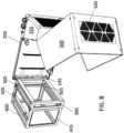
FIG. 8 is a perspective view of an exemplary modular data center of embodiments of the present disclosure in an open configuration; -
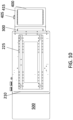
FIG. 9 is a front elevational view of an exemplary modular data center of embodiments of the present disclosure in an open configuration; -
FIG. 10 is a rear elevational view of an exemplary modular data center of embodiments of the present disclosure in an open configuration; -
FIG. 11 is a right elevational view of an exemplary modular data center of embodiments of the present disclosure in an open configuration; -
FIG. 12 is a left elevational view of an exemplary modular data center of embodiments of the present disclosure in an open configuration; -
FIG. 13 is a view from the top of an exemplary modular data center of embodiments of the present disclosure in an open configuration; -
FIG. 14 is a view from the bottom of an exemplary modular data center of embodiments of the present disclosure in an open configuration; -
FIG. 15 is an exploded view of an exemplary modular data center of embodiments of the present disclosure; -
FIG. 16 is an isometric view of an exemplary modular data center of embodiments of the present disclosure in an open configuration; -
FIG. 17 is a close-up view of a portion of a base electrical module of an exemplary modular data center of embodiments of the present disclosure; and -
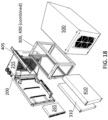
FIG. 18 is an exploded view of an exemplary modular data center of another embodiment of the present disclosure. - This disclosure is not limited in its application to the details of construction and the arrangement of components set forth in the following description or illustrated in the drawings. The principles set forth in this disclosure are capable of being provided in other embodiments and of being practiced or of being carried out in various ways. Also, the phraseology and terminology used herein is for the purpose of description and should not be regarded as limiting. The use of "including," "comprising," "having," "containing", "involving", and variations thereof herein, is meant to encompass the items listed thereafter and equivalents thereof as well as additional items.
- All-in-one equipment racks may be used in microdata centers for edge application, which are typically deployed in closets or other locations without adequate cooling resources. These applications use racks sealed from the surrounding ambient air for physical security and environment protection. The equipment racks require highly varied requirements, including but not limited to environment, serviceability, security, and management.
- As used herein, "enclosures" and "racks" are used to describe apparatus designed to support electronic equipment.
- The present disclosure is directed to a modular data center including a base electrical module that is configured to be mounted on a wall. The base electrical module includes a compartment into which a power line enters and lands to a terminal block with a connection to a maintenance bypass switch. The base electrical module further includes a fan compartment and the ability to run network cables through an optional patch panel.
- The modular data center further includes a removable first frame that is hinged to one end of the base electrical module, e.g., a left edge of the base electrical module, with a separate second frame for IT equipment that attaches to the hinged first rack frame. The modular data center further includes a door or cover is connected to the base electrical module, e.g., a right edge of the base electrical module, by hinges but that can also be removably attached with hardware such as bolts, clips, or other forms of fasteners.
- The base electrical module of the modular data center of embodiments of the present disclosure address issues associated with prior base module concepts, including: 1) current wall mount IT racks are extremely difficult to install due to their size and weight since current wall mount IT racks typically embody one large metal box; and 2) current wall mount IT racks are very complicated to configure due to the collection of components often required in that they do not include integrated power terminals/connections, a maintenance bypass switch, filtered fan compartments, and removable racking frame.
- The
modular data center 100 of embodiments of the present disclosure addresses these issues by separating and dividing the overall structure into three core modules with integrated technical components. Specifically, themodular data center 100 includes the baseelectrical module 200, which embodies a metal box having an integratedpower connection terminal 270, input andoutput connectors 275, amaintenance bypass switch 205, and afan module 220. Thepower connection terminal 270 is illustrated in the close-up view of a portion of the base electrical module inFIG. 17 in which acover 215 that would normally cover thepower connection terminal 270 is shown removed. In one embodiment, the baseelectrical module 200 is mounted on the wall by one ormore cleats 225, which creates a small space, e.g., one-quarter to one-half inch, between a back of the baseelectrical module 200 and the wall. - The base
electrical module 200 is configured to provide control and power to IT equipment mounted on anIT equipment rack 415, with the baseelectrical module 200 being external to theIT equipment rack 415. The baseelectrical module 200 can include a variety of components, including but not limited to a PDU, an additional PDU, one or more hardwire connections, an accommodation or feature for a subsequent module to be attached, one or more power distribution unit connections, a UPS, a management and security module, and a user interface coupled to the management and security module. - The
modular data center 100 further includes a removableIT frame structure cover 500. As shown and described below, there is a smaller firstIT frame structure 300 secured to thebase module 200 and a larger secondIT frame structure 400 that is supported by the smaller firstIT frame structure 300. The firstIT frame structure 300 is configured to support a UPS 310 (shown in the exploded view ofFIG. 14 ) to provide emergency power. The firstIT frame structure 300 includes aUPS rack 315 including mounting features such as apertures or slots to which aUPS 310 may be attached. TheUPS rack 315 may be formed integral with the firstIT frame structure 300 or a separate element that is secures to the first IT frame structure with fasteners, for example, nuts, bolts, screws, or other fasteners known in the art. - The second
IT frame structure 400 is configured to supportIT equipment 410, for example, one or more servers (shown in the exploded view ofFIG. 14 ) that receives power from the baseelectrical module 200. The secondIT frame structure 400 includes anIT rack 415 including mounting features such as apertures or slots to whichIT equipment 410 may be attached. TheIT rack 415 may be formed integral with the secondIT frame structure 400 or a separate element that is secures to the second IT frame structure with fasteners, for example, nuts, bolts, screws, or other fasteners known in the art. In one embodiment, the secondIT frame structure 400 may include one or more power distribution units (PDUs) 405 to provide power connections to theIT equipment 410. - In one embodiment, the base
electrical module 200 of the modular data center includes several conduit openings, e.g., threeconduit openings electrical module 200, one (230) for power and two (235, 240) for network cables. Power connection runs into a small compartment in the baseelectrical module 200 in which theterminal block 270 and thebypass switch 205 are located, as well as twosockets 275 for input and output power to theUPS 310 and apower connection 280 for thefan module 220. (SeeFIG. 17 .) The baseelectrical module 200 also accommodateshinges 245 on the left edge of the baseelectrical module 200 for the removable frame structures. Afan module 220 is provided on the right side of the baseelectrical module 200 and includeshinges 250 on the right edge of the baseelectrical module 200 to attach thecover 500. It is to be understood that in various embodiments each of hinges 245, 250 can embody any type of hinge, such as a barrel hinge, lift-off hinge, a corner hinge, a continuous or piano hinge, or a leaf hinge, to name a few. - In some embodiments, the base
electrical module 200 further includes a temperature and/orhumidity sensor 260 mounted to an internal wall thereof. In some embodiments, the temperature and/orhumidity sensor 260 may also include additional features and functionality, for example, a security system, camera, internet gateway, etc. The temperature and/orhumidity sensor 260 may be, for example, one of the NetBotz™ rack sensor/monitor modules available from Schneider Electric. - The
first frame 300 is sized to fit a 1U lithium-ion UPS 310 and has four cleats or clips 305 designed to hold asecond frame structure 400, for example, a second frame structure sized for 6U of rack space. -
FIGS. 1-7 are a perspective view, a front elevational view, a rear elevational view, a right elevational view, a left elevational view, a view from the top, and a view from the bottom, respectively, of an exemplarymodular data center 100 of embodiments of the present disclosure in a closed configuration. As shown, when fully assembled, themodular data center 100 achieves a compact design. As previously described, the modular data center includes the baseelectrical module 200 having aUPS bypass switch 205, apower connection terminal 270 coupled to thebypass switch 205, and aUPS power connector 275. (SeeFIG. 17 .) - The
modular data center 100 further includes aUPS 310 housed by the firstIT frame structure 300 coupled to the baseelectrical module 200 and one or more items ofIT equipment 410 housed by the secondIT frame structure 400, which is coupled to the baseelectrical module 200 via the firstIT frame structure 300. In one embodiment, theUPS 310 contains an alternating current ("AC") power back-up and battery, or reliable direct current ("DC") power for applications that require direct current. - In some embodiments, the
UPS 310 can be connected, disconnected, or replaced by a person skilled in the art of managing IT equipment. This UPS 310 can be easily configured and integrated at a domestic or an international facility. TheUPS 310 can be configured with components manufactured by various entities at partner module integration sites. When theUPS 310 is paired with a baseelectrical module 200 having a service bypass function, theUPS 310 can be serviced, upgraded, and/or swapped without service interruption of theIT equipment 410. - In some embodiments, the
UPS 310 can be used to control power within themodular data center 100 and monitor certain aspects of themodular data center 100 including providing power readings and/or outlet switching. In one embodiment, the information can be communicated to an operator by an integrated network to a display, which can also function as a management controller. -
FIGS. 8-14 are a perspective view, a front elevational view, a rear elevational view, a right elevational view, a left elevational view, a view from the top, and a view from the bottom, respectively, of themodular data center 100 with thecover 500 in an open position. As shown, the firstIT frame structure 200 and the secondIT frame structure 300 are configured achieve a nested position adjacent the baseelectrical module 200. The baseelectrical module 200 is further shown to have afan module compartment 255 that houses afan module 220 to cool electronic components within theIT frame structures cover 500 includes anopening 505 having a fan guard to allow airflow through themodular data center 100 over theUPS 310 and theIT equipment 410 when thecover 500 is in the closed position. Thecover 500 can include a seal around a peripheral edge to seal thecover 500 when in the closed position shown inFIGS. 1-7 . As previously described, the firstIT frame structure 300 is configured to support theUPS 310 to provide emergency power to theIT equipment 410 supported by the secondIT frame structure 400. Further, the secondIT frame structure 400 may include one or more PDUs 405 to provide power connections to theIT equipment 410. -
FIGS. 8 ,9 ,13 , and14 illustrate the firstIT frame structure 300, which is configured to house theUPS 310 that receives power from theUPS power connector 275 associated with the baseelectrical module 200, and the secondIT frame structure 400, which is configured to houseIT equipment 410 that receives power from the baseelectrical module 200. As shown, the baseelectrical module 200 is external to theIT equipment rack 415 supported by the secondIT frame structure 400. - The
IT equipment rack 415 can be configured to receive one or more pieces ofIT equipment 410, e.g., servers. TheIT equipment rack 415 can be configured to achieve variable U-space distances, e.g., 4-6 U. In one embodiment, theIT equipment rack 415 can be configured as a 19-inch rack having 21-inch rails. TheIT equipment 410, when housed by theIT equipment rack 415, can be accessed from the front and back of theIT equipment rack 415 when theIT frame structure 400 is in its open position with respect to the baseelectrical module 200. TheIT equipment 410 further can be accessed from the top and/or the bottom of theIT equipment rack 415. -
FIGS. 8 ,9 , and13 illustrate the first and secondIT frame structures cover 500 in a fully open position. As shown, the baseelectrical module 200 includes thefan compartment 255 that receives thefan module 220. Thefan module 220 is provided to cool theUPS 310 and theIT equipment 410 housed by the first and secondIT frame structures -
FIG. 9 illustrates the location of thebypass switch 205 within the baseelectrical module 200. - In some embodiments, a
patch panel 265 having CAT 5 cables (shown in exploded view ofFIG. 14 with cables omitted for clarity) can be integrated into the baseelectrical module 200 of themodular data center 100. Thepatch panel 265 may be disposed withincompartment 265A (shown inFIG. 15 ) when themodular data center 100 is assembled, as illustrated inFIG. 16 . - In some embodiments, an Internet gateway device can be integrated into the base
electrical module 200 of themodular data center 100, for example, as part of the temperature and/orhumidity sensor 260 as discussed above, or as a separate module. - In some embodiments, the PDU 405 (or multiple PDUs 405) can be provided in the base
electrical module 200 and/or the firstIT frame structure 300. - In some embodiments, the base
electrical module 200 can include a visual indication 210 (see, e.g.,FIG. 3 ) of the status of the modular data center. For example, a set of LEDs (green, amber and red LEDs) may be provided on the rear of the baseelectrical module 200 to reflect off a wall on which themodular datacenter 100 is mounted to provide an operator an indication of a status of the modular data center, with green representing an operational status, amber representing a warning status, and red representing an alarm or alert status. - In some embodiments, the IT equipment and the modules described herein are components that can be configured to be hot-swappable.
- It should be understood that the
modular data center 100 can be provided in a variety of shapes and sizes, and configured to support different power configurations. For example, in an alternate embodiment illustrated inFIG. 18 the first and secondIT frame structures FIGS. 15 and18 theUPS 310 andIT equipment module 410 are shown removed from the positions they would occupy within theirrespective frames - Various aspects and functions in accordance with the present embodiments may be implemented as specialized hardware or software executing in one or more computer systems, which may include a computer system that includes processor, memory, bus, interface, and storage. The processor may perform a series of instructions that result in manipulated data. The processor may be a commercially available processor, multiprocessor, microprocessor, or controller as many other processors and controllers are available. The processor may be connected to other system elements, including one or more memory devices, by bus.
- Memory may be used for storing programs and data during operation of computer system. Thus, memory may be a relatively high performance, volatile, random access memory such as a dynamic random access memory (DRAM) or static memory (SRAM). However, memory may include any device for storing data, such as a disk drive or other nonvolatile, non-transitory, storage device. Various embodiments in accordance with the present disclosure may organize memory into particularized and, in some cases, unique structures to perform the aspects and functions disclosed herein.
- Components of the computer system may be coupled by an interconnection element, such as a bus, which may include one or more physical busses, for example, busses between components that are integrated within a same machine, but may include any communication coupling between system elements including specialized or standard computing bus technologies such as IDE, SCSI, PCI, and InfiniBand. Thus, the bus enables communications, for example, data and instructions, to be exchanged between system components of computer system.
- The computer system also may include one or more interface devices, such as input devices, output devices, and combination input/output devices. Interface devices may receive input or provide output. More particularly, output devices may render information for external presentation. The interface devices may include, for example, one or more graphical user interfaces that may be disposed proximate to or separate from other components of the computer system. A graphical user interface of the computer system may, for example, be displayed through a web browser that accesses information from the memory. Input devices may accept information from external sources. Examples of interface devices include keyboards, mouse devices, trackballs, microphones, touch screens, printing devices, display screens, speakers, network interface cards, etc. The interface devices allow computer system to exchange information and communicate with external entities, such as users and other systems.
- The storage system may include a computer readable and writeable, nonvolatile, non-transitory, storage medium in which instructions are stored that define a program to be executed by the processor. The program to be executed by the processor may cause the processor or computer system to perform any one or more embodiments of the methods disclosed herein. The storage system also may include information that is recorded, on or in, the medium, and this information may be processed by the program. More specifically, the information may be stored in one or more data structures specifically configured to conserve storage space or increase data exchange performance. The instructions may be persistently stored as encoded signals, and the instructions may cause a processor to perform any of the functions described herein. The medium may, for example, be optical disk, magnetic disk, or flash memory, among others. In operation, the processor or some other controller may cause data to be read from the nonvolatile recording medium into another memory, such as memory, that allows for faster access to the information by the processor than does the storage medium included in storage system. The memory may be located in storage system or in memory, however, processor may manipulate the data within the memory, and then may copy the data to the medium associated with storage system after processing is completed. A variety of components may manage data movement between the medium and integrated circuit memory element and the presently described embodiments are not limited thereto. Further, the embodiments are not limited to a particular memory system or data storage system. Portions of the memory or storage system may be included in the same computer system as other components of the computer system or may be resident in a cloud-based system that is accessible via the internet or other communications system or protocol.
- Although the computer system is described by way of example as one type of computer system upon which various aspects and functions in accordance with the present embodiments may be practiced, any aspects of the presently disclosed embodiments are not limited to being implemented on the computer system. Various aspects and functions in accord with the presently disclosed embodiments may be practiced on one or more computers having a different architectures or components. For instance, computer system may include specially-programmed, special-purpose hardware, such as for example, an application-specific integrated circuit (ASIC) tailored to perform a particular operation disclosed herein. While another embodiment may perform the same function using several general-purpose computing devices running MAC OS System X with Motorola PowerPC processors and several specialized computing devices running proprietary hardware and operating systems.
- The computer system may be a computer system including an operating system that manages at least a portion of the hardware elements included in computer system. Usually, a processor or controller, such as processor, executes a commercially available operating system. Many types of operating systems may be used, and embodiments are not limited to any particular implementation.
- The processor and operating system together define a computer platform for which application programs in high-level programming languages may be written. These component applications may be executable, intermediate, for example, C-, bytecode or interpreted code which communicates over a communication network, for example, the Internet, using a communication protocol, for example, TCP/IP. Similarly, aspects in accord with the presently disclosed embodiments may be implemented using an object-oriented programming language, such as .Net, SmallTalk, Java, C++, Ada, or C# (C-Sharp). Other object-oriented programming languages may also be used. Alternatively, functional, scripting, or logical programming languages may be used.
- Additionally, various aspects and functions in accordance with the presently disclosed embodiments may be implemented in a non-programmed environment, for example, documents created in HTML, XML, or other format that, when viewed in a window of a browser program, render aspects of a graphical-user interface or perform other functions. Further, various embodiments in accord with the present disclosure may be implemented as programmed or non-programmed elements, or any combination thereof. For example, a web page may be implemented using HTML while a data object called from within the web page may be written in C++. Thus, the presently disclosed embodiments are not limited to a specific programming language and any suitable programming language could also be used.
- A computer system included within an embodiment may perform additional functions outside the scope of the presently disclosed embodiments. For instance, aspects of the system may be implemented using an existing commercial product, such as, for example, Database Management Systems such as SQL Server available from Microsoft of Seattle WA., Oracle Database from Oracle of Redwood Shores, CA, and MySQL from MySQL AB, a subsidiary of Oracle or integration software such as Web Sphere middleware from IBM of Armonk, NY. However, a computer system running, for example, SQL Server may be able to support both aspects in accord with the presently disclosed embodiments and databases for sundry applications.
- It is to be appreciated that examples of the methods, systems, and apparatuses discussed herein are not limited in application to the details of construction and the arrangement of components set forth in the following description or illustrated in the accompanying drawings. The methods, systems, and apparatuses are capable of implementation in other examples and of being practiced or of being carried out in various ways. Examples of specific implementations are provided herein for illustrative purposes only and are not intended to be limiting. Examples disclosed herein may be combined with other examples in any manner consistent with at least one of the principles disclosed herein, and references to "an example," "some examples," "an alternate example," "various examples," "one example" or the like are not necessarily mutually exclusive and are intended to indicate that a particular feature, structure, or characteristic described may be included in at least one example. The appearances of such terms herein are not necessarily all referring to the same example. Also, the phraseology and terminology used herein is for the purpose of description and should not be regarded as limiting. The use herein of "including," "comprising," "having," "containing," "involving," and variations thereof is meant to encompass the items listed thereafter and equivalents thereof as well as additional items. References to "or" may be construed as inclusive so that any terms described using "or" may indicate any of a single, more than one, and all of the described terms. Any references to front and back, left and right, top and bottom, upper and lower, and vertical and horizontal are intended for convenience of description, not to limit the present systems and methods or their components to any one positional or spatial orientation.
- Having thus described several aspects of at least one embodiment of this disclosure, it is to be appreciated various alterations, modifications, and improvements will readily occur to those skilled in the art. Such alterations, modifications, and improvements are intended to be part of this disclosure, and are intended to be within the scope of the disclosure. Accordingly, the foregoing description and drawings are by way of example only.
- Further examples are provided in the following clauses:
- Clause 1. A modular data center comprising:
- a base electrical module including an uninterruptible power supply ("UPS") bypass switch and a UPS power connector;
- a first frame coupled to the base electrical module and configured to house a UPS that receives power from the UPS power connector; and
- a second frame coupled to the base electrical module and configured to house IT equipment that receives power from the base electrical module, the base electrical module being external to the second frame.
- Clause 2. The modular data center of clause 1, wherein the base electrical module further includes a power connection terminal coupled to the bypass switch.
- Clause 3. The modular data center of clause 1, further comprising a UPS rack included in the first frame, the UPS rack configured for mounting the UPS thereto.
- Clause 4. The modular data center of clause 1, further comprising a UPS rack coupled to the first frame.
- Clause 5. The modular data center of clause 1, further comprising an IT equipment rack included in the second frame, the IT equipment rack configured for mounting the IT equipment thereto.
- Clause 6. The modular data center of clause 1, further comprising an IT equipment rack coupled to the second frame.
-
Clause 7. The modular data center of clause 1, wherein the base electrical module further includes a fan module configured to direct air through the IT equipment rack. - Clause 8. The modular data center of clause 1, further comprising:
- a fan module included in the base electrical module and configured to direct air through the second frame; and
- a casing coupled to the fan module with a hinge, the casing enclosing the base electrical module, first frame, and second frame when in a closed position.
- Clause 9. The modular data center of clause 1, wherein the base electrical module is configured to be mounted to a wall.
-
Clause 10. The modular data center of clause 1, wherein the first frame is coupled to the base electrical module with a hinge. - Clause 11. The modular data center of clause 1, wherein the second frame is indirectly coupled to the base electrical module.
- Clause 12. The modular data center of clause 1, further comprising a UPS rack included in the first frame and an IT equipment rack included in the second frame.
- Clause 13. The modular data center of clause 1, wherein the second frame is removably supported by the first frame.
- Clause 14. The modular data center of clause 1, wherein the second frame is removably clipped to the first frame.
- Clause 15. The modular data center of clause 1, further comprising a casing removably coupleable to the base electrical module, the casing enclosing the base electrical module, first frame, and second frame when coupled to the base electrical module.
- Clause 16. The modular data center of clause 1, further comprising a casing coupled to the base electrical module with a hinge, the casing enclosing the base electrical module, the first frame, and the second frame when in a closed position.
- Clause 17. The modular data center of clause 1, further comprising a power distribution unit having a plurality of outlets mounted on the second frame and configured to provide power from the base electrical module to the IT equipment.
- Clause 18. The modular data center of clause 1, wherein the base electrical module further includes a patch panel.
- Clause 19. The modular data center of clause 1, wherein the base electrical module further includes an Internet gateway device.
- Clause 20. The modular data center of clause 1, further comprising a power distribution unit having a plurality of outlets mounted on the first frame.
- Clause 21. The modular data center of clause 1, wherein the base electrical module further includes a visual indicator of status of the modular data center.
- Clause 22. The modular data center of clause 1, further comprising at least one backup UPS.
- Clause 23. The modular data center of clause 1, further comprising at least one server.
- Clause 24. A method of assembling and installing a modular data center, the method comprising:
- installing a base electrical module on a wall, the base electrical module including an uninterruptible power supply ("UPS") bypass switch and a UPS power connector;
- hingedly connecting a first frame to the base electrical module, the first frame configured to house a UPS that receives power from the UPS power connector; and
- connecting a second frame to the first frame, the second frame configured to house IT equipment that receives power from the base electrical module, the base electrical module being external to the IT equipment rack.
-
Clause 25. The method of clause 24, further comprising securing a power distribution unit to the second frame. - Clause 26. The method of clause 24, further comprising securing a backup UPS module to the first frame.
- Clause 27. The method of clause 24, further comprising securing a cover to the base electrical module.
Claims (16)
- A modular data center comprising:a base electrical module including an uninterruptible power supply ("UPS") bypass switch and a UPS power connector;a first frame coupled to the base electrical module and configured to house a UPS that receives power from the UPS power connector; anda second frame coupled to the base electrical module and configured to house IT equipment that receives power from the base electrical module, the base electrical module being external to the second frame.
- The modular data center of claim 1, wherein the base electrical module further includes a power connection terminal coupled to the bypass switch.
- The modular data center of claim 1 or of claim 2, further comprising a UPS rack, whereby the UPS rack is one or more of:- included in the first frame, the UPS rack being configured for mounting the UPS thereto; and- coupled to the first frame.
- The modular data center of any of the above claims, further comprising an IT equipment rack, whereby the IT equipment rack is one or more of:- included in the second frame, the IT equipment rack being configured for mounting the IT equipment thereto; and- coupled to the second frame.
- The modular data center of claim 4, wherein the base electrical module further includes a fan module configured to direct air through the IT equipment rack.
- The modular data center of any of the above claims, further comprising:a fan module included in the base electrical module and configured to direct air through the second frame; anda casing coupled to the fan module with a hinge, the casing enclosing the base electrical module, first frame, and second frame when in a closed position.
- The modular data center of any of the above claims, wherein the base electrical module is configured to be mounted to a wall.
- The modular data center of any of the above claims, wherein the first frame is coupled to the base electrical module with a hinge.
- The modular data center of any of the above claims, wherein the second frame is one or more of:- indirectly coupled to the base electrical module;- removably supported by the first frame; and- removably clipped to the first frame.
- The modular data center of any of the claims 1, 2 or 5-9, the modular data center further comprising a UPS rack included in the first frame and an IT equipment rack included in the second frame.
- The modular data center of any of the above claims, further comprising a casing, whereby the casing is one or more of:- removably coupleable to the base electrical module, the casing enclosing the base electrical module, first frame, and second frame when coupled to the base electrical module; and- coupled to the base electrical module with a hinge, the casing enclosing the base electrical module, the first frame, and the second frame when in a closed position.
- The modular data center of any of the above claims, further comprising a power distribution unit having one or more of:- a plurality of outlets mounted on the second frame and configured to provide power from the base electrical module to the IT equipment; and- a plurality of outlets mounted on the first frame.
- The modular data center of any of the above claims, wherein the base electrical module further includes one or more of:- a patch panel;- an Internet gateway device; and- a visual indicator of status of the modular data center.
- The modular data center of any of the above claims, further comprising one or more of:- a backup UPS; and- a server.
- A method of assembling and installing a modular data center, the method comprising:installing a base electrical module on a wall, the base electrical module including an uninterruptible power supply ("UPS") bypass switch and a UPS power connector;hingedly connecting a first frame to the base electrical module, the first frame configured to house a UPS that receives power from the UPS power connector; andconnecting a second frame to the first frame, the second frame configured to house IT equipment that receives power from the base electrical module, the base electrical module being external to the IT equipment rack.
- The method of claim 15, further comprising securing one or more of:- a power distribution unit to the second frame;- a backup UPS module to the first frame; and- a cover to the base electrical module.
Applications Claiming Priority (2)
| Application Number | Priority Date | Filing Date | Title |
|---|---|---|---|
| US202263389465P | 2022-07-15 | 2022-07-15 | |
| US18/211,363 US20240023268A1 (en) | 2022-07-15 | 2023-06-19 | Optimized micro data center |
Publications (1)
| Publication Number | Publication Date |
|---|---|
| EP4307847A1 true EP4307847A1 (en) | 2024-01-17 |
Family
ID=87280192
Family Applications (1)
| Application Number | Title | Priority Date | Filing Date |
|---|---|---|---|
| EP23185047.0A Pending EP4307847A1 (en) | 2022-07-15 | 2023-07-12 | Modular data centers |
Country Status (2)
| Country | Link |
|---|---|
| US (1) | US20240023268A1 (en) |
| EP (1) | EP4307847A1 (en) |
Citations (2)
| Publication number | Priority date | Publication date | Assignee | Title |
|---|---|---|---|---|
| EP3451489A1 (en) * | 2017-08-31 | 2019-03-06 | Schneider Electric IT Corporation | Rack mount ups dock with bypass capability |
| US20210251101A1 (en) * | 2020-02-11 | 2021-08-12 | Schneider Electric It Corporation | Base electrical module for modular data center |
Family Cites Families (16)
| Publication number | Priority date | Publication date | Assignee | Title |
|---|---|---|---|---|
| US5584396A (en) * | 1995-05-17 | 1996-12-17 | Dell Usa Lp | Sliding pivoting storage apparatus |
| US5684671A (en) * | 1995-08-22 | 1997-11-04 | Sequent Computer Systems, Inc. | Packaging architecture for a data server |
| US6317320B1 (en) * | 2000-09-19 | 2001-11-13 | Marconi Communications, Inc. | Cooling system for electronic components in an equipment enclosure |
| US6563048B2 (en) * | 2000-10-27 | 2003-05-13 | Liebert Corporation | Ancillary cabinet system for an uninterruptible power supply |
| US6967283B2 (en) * | 2001-03-20 | 2005-11-22 | American Power Conversion Corporation | Adjustable scalable rack power system and method |
| US6538879B2 (en) * | 2001-07-31 | 2003-03-25 | Lite-On Enclosure Inc. | Assembly frame of computer housing capable of rotating and positioning |
| DE102005026181A1 (en) * | 2005-06-06 | 2006-12-07 | Rittal Res Electronic Systems Gmbh & Co. Kg | Component carrier, has two module carriers arranged together, and plug-in cards electrically contacted at rear-side carrier by plug-in connections, where module carriers are detachably connected with rear-sided carrier |
| US7542268B2 (en) * | 2006-03-17 | 2009-06-02 | Eaton Corporation | Modular electronic systems and methods using flexible power distribution unit interface |
| US8562358B2 (en) * | 2008-10-07 | 2013-10-22 | Molex Incorporated | Patch panel assembly for use with data networks |
| US8913393B2 (en) * | 2011-10-17 | 2014-12-16 | Innovation First, Inc. | Wall-mountable support rack for equipment |
| WO2015128253A1 (en) * | 2014-02-25 | 2015-09-03 | Abb Technology Ag | Horizontal uninterrupted power supply design |
| JP6467906B2 (en) * | 2014-12-19 | 2019-02-13 | 富士通株式会社 | Information processing system, information processing method, information processing program, and information processing apparatus |
| US9635778B2 (en) * | 2014-12-20 | 2017-04-25 | Aic Inc. | Modular protective housing structure |
| US10025357B2 (en) * | 2015-06-15 | 2018-07-17 | Seagate Technology Llc | Enclosure system for computing equipment |
| WO2017131766A1 (en) * | 2016-01-29 | 2017-08-03 | Hewlett Packard Enterprise Development Lp | Coupling a power module to a power distribution rack |
| US11234340B2 (en) * | 2019-10-15 | 2022-01-25 | Dell Products, L.P. | Modular data center power distribution system |
-
2023
- 2023-06-19 US US18/211,363 patent/US20240023268A1/en active Pending
- 2023-07-12 EP EP23185047.0A patent/EP4307847A1/en active Pending
Patent Citations (2)
| Publication number | Priority date | Publication date | Assignee | Title |
|---|---|---|---|---|
| EP3451489A1 (en) * | 2017-08-31 | 2019-03-06 | Schneider Electric IT Corporation | Rack mount ups dock with bypass capability |
| US20210251101A1 (en) * | 2020-02-11 | 2021-08-12 | Schneider Electric It Corporation | Base electrical module for modular data center |
Also Published As
| Publication number | Publication date |
|---|---|
| US20240023268A1 (en) | 2024-01-18 |
Similar Documents
| Publication | Publication Date | Title |
|---|---|---|
| US11602069B2 (en) | Base electrical module for modular data center | |
| US8068340B1 (en) | Power supply with reversible airflow design | |
| US7983039B1 (en) | Reversible airflow fan tray design for electronic device in a data center | |
| US7256995B2 (en) | Electronics module | |
| US9066444B2 (en) | Power supply unit with articulating fan assembly | |
| TWI461136B (en) | Rack mounted computer system and cable management mechanism thereof | |
| US6667891B2 (en) | Computer chassis for dual offset opposing main boards | |
| US7423870B2 (en) | Blade server assembly | |
| KR100859760B1 (en) | Scalable Internet Engine | |
| US20070027948A1 (en) | Server blades connected via a wireless network | |
| US20040264126A1 (en) | Universal laptop case | |
| US8670241B2 (en) | Blade device enclosure | |
| US12068635B2 (en) | Modular power system | |
| CN105739644A (en) | front access device | |
| US20130141243A1 (en) | Server | |
| CN210442733U (en) | High-efficient big data processing apparatus | |
| US20240023268A1 (en) | Optimized micro data center | |
| CN114860039A (en) | Modular edge computing industrial personal computer | |
| US11234340B2 (en) | Modular data center power distribution system | |
| CN117406834A (en) | Optimized micro data center | |
| CN216260828U (en) | High-capacity intelligent chemical reagent management and storage device | |
| CN111752345A (en) | Server | |
| CN210514736U (en) | Distribution frame for information communication cabinet | |
| CN113941376A (en) | High-capacity intelligent chemical reagent management and storage system and device | |
| EP4391751A1 (en) | Modular containerized ups |
Legal Events
| Date | Code | Title | Description |
|---|---|---|---|
| PUAI | Public reference made under article 153(3) epc to a published international application that has entered the european phase |
Free format text: ORIGINAL CODE: 0009012 |
|
| STAA | Information on the status of an ep patent application or granted ep patent |
Free format text: STATUS: THE APPLICATION HAS BEEN PUBLISHED |
|
| AK | Designated contracting states |
Kind code of ref document: A1 Designated state(s): AL AT BE BG CH CY CZ DE DK EE ES FI FR GB GR HR HU IE IS IT LI LT LU LV MC ME MK MT NL NO PL PT RO RS SE SI SK SM TR |
|
| STAA | Information on the status of an ep patent application or granted ep patent |
Free format text: STATUS: REQUEST FOR EXAMINATION WAS MADE |
|
| 17P | Request for examination filed |
Effective date: 20240522 |
|
| RBV | Designated contracting states (corrected) |
Designated state(s): AL AT BE BG CH CY CZ DE DK EE ES FI FR GB GR HR HU IE IS IT LI LT LU LV MC ME MK MT NL NO PL PT RO RS SE SI SK SM TR |