EP4307653A1 - Camera structure and electronic device - Google Patents
Camera structure and electronic device Download PDFInfo
- Publication number
- EP4307653A1 EP4307653A1 EP22790900.9A EP22790900A EP4307653A1 EP 4307653 A1 EP4307653 A1 EP 4307653A1 EP 22790900 A EP22790900 A EP 22790900A EP 4307653 A1 EP4307653 A1 EP 4307653A1
- Authority
- EP
- European Patent Office
- Prior art keywords
- axis
- gimbal support
- gimbal
- group
- carrier
- Prior art date
- Legal status (The legal status is an assumption and is not a legal conclusion. Google has not performed a legal analysis and makes no representation as to the accuracy of the status listed.)
- Granted
Links
Images






Classifications
-
- H—ELECTRICITY
- H04—ELECTRIC COMMUNICATION TECHNIQUE
- H04N—PICTORIAL COMMUNICATION, e.g. TELEVISION
- H04N23/00—Cameras or camera modules comprising electronic image sensors; Control thereof
- H04N23/60—Control of cameras or camera modules
- H04N23/68—Control of cameras or camera modules for stable pick-up of the scene, e.g. compensating for camera body vibrations
- H04N23/682—Vibration or motion blur correction
- H04N23/685—Vibration or motion blur correction performed by mechanical compensation
- H04N23/687—Vibration or motion blur correction performed by mechanical compensation by shifting the lens or sensor position
-
- H—ELECTRICITY
- H04—ELECTRIC COMMUNICATION TECHNIQUE
- H04N—PICTORIAL COMMUNICATION, e.g. TELEVISION
- H04N23/00—Cameras or camera modules comprising electronic image sensors; Control thereof
- H04N23/50—Constructional details
-
- G—PHYSICS
- G03—PHOTOGRAPHY; CINEMATOGRAPHY; ANALOGOUS TECHNIQUES USING WAVES OTHER THAN OPTICAL WAVES; ELECTROGRAPHY; HOLOGRAPHY
- G03B—APPARATUS OR ARRANGEMENTS FOR TAKING PHOTOGRAPHS OR FOR PROJECTING OR VIEWING THEM; APPARATUS OR ARRANGEMENTS EMPLOYING ANALOGOUS TECHNIQUES USING WAVES OTHER THAN OPTICAL WAVES; ACCESSORIES THEREFOR
- G03B30/00—Camera modules comprising integrated lens units and imaging units, specially adapted for being embedded in other devices, e.g. mobile phones or vehicles
-
- G—PHYSICS
- G03—PHOTOGRAPHY; CINEMATOGRAPHY; ANALOGOUS TECHNIQUES USING WAVES OTHER THAN OPTICAL WAVES; ELECTROGRAPHY; HOLOGRAPHY
- G03B—APPARATUS OR ARRANGEMENTS FOR TAKING PHOTOGRAPHS OR FOR PROJECTING OR VIEWING THEM; APPARATUS OR ARRANGEMENTS EMPLOYING ANALOGOUS TECHNIQUES USING WAVES OTHER THAN OPTICAL WAVES; ACCESSORIES THEREFOR
- G03B5/00—Adjustment of optical system relative to image or object surface other than for focusing
- G03B5/06—Swinging lens about normal to the optical axis
-
- H—ELECTRICITY
- H04—ELECTRIC COMMUNICATION TECHNIQUE
- H04N—PICTORIAL COMMUNICATION, e.g. TELEVISION
- H04N23/00—Cameras or camera modules comprising electronic image sensors; Control thereof
- H04N23/50—Constructional details
- H04N23/54—Mounting of pick-up tubes, electronic image sensors, deviation or focusing coils
-
- H—ELECTRICITY
- H04—ELECTRIC COMMUNICATION TECHNIQUE
- H04N—PICTORIAL COMMUNICATION, e.g. TELEVISION
- H04N23/00—Cameras or camera modules comprising electronic image sensors; Control thereof
- H04N23/57—Mechanical or electrical details of cameras or camera modules specially adapted for being embedded in other devices
-
- H—ELECTRICITY
- H04—ELECTRIC COMMUNICATION TECHNIQUE
- H04N—PICTORIAL COMMUNICATION, e.g. TELEVISION
- H04N23/00—Cameras or camera modules comprising electronic image sensors; Control thereof
- H04N23/60—Control of cameras or camera modules
- H04N23/68—Control of cameras or camera modules for stable pick-up of the scene, e.g. compensating for camera body vibrations
- H04N23/681—Motion detection
- H04N23/6812—Motion detection based on additional sensors, e.g. acceleration sensors
-
- H—ELECTRICITY
- H04—ELECTRIC COMMUNICATION TECHNIQUE
- H04N—PICTORIAL COMMUNICATION, e.g. TELEVISION
- H04N23/00—Cameras or camera modules comprising electronic image sensors; Control thereof
- H04N23/60—Control of cameras or camera modules
- H04N23/68—Control of cameras or camera modules for stable pick-up of the scene, e.g. compensating for camera body vibrations
- H04N23/682—Vibration or motion blur correction
- H04N23/685—Vibration or motion blur correction performed by mechanical compensation
-
- G—PHYSICS
- G03—PHOTOGRAPHY; CINEMATOGRAPHY; ANALOGOUS TECHNIQUES USING WAVES OTHER THAN OPTICAL WAVES; ELECTROGRAPHY; HOLOGRAPHY
- G03B—APPARATUS OR ARRANGEMENTS FOR TAKING PHOTOGRAPHS OR FOR PROJECTING OR VIEWING THEM; APPARATUS OR ARRANGEMENTS EMPLOYING ANALOGOUS TECHNIQUES USING WAVES OTHER THAN OPTICAL WAVES; ACCESSORIES THEREFOR
- G03B2205/00—Adjustment of optical system relative to image or object surface other than for focusing
- G03B2205/0007—Movement of one or more optical elements for control of motion blur
- G03B2205/0023—Movement of one or more optical elements for control of motion blur by tilting or inclining one or more optical elements with respect to the optical axis
-
- G—PHYSICS
- G03—PHOTOGRAPHY; CINEMATOGRAPHY; ANALOGOUS TECHNIQUES USING WAVES OTHER THAN OPTICAL WAVES; ELECTROGRAPHY; HOLOGRAPHY
- G03B—APPARATUS OR ARRANGEMENTS FOR TAKING PHOTOGRAPHS OR FOR PROJECTING OR VIEWING THEM; APPARATUS OR ARRANGEMENTS EMPLOYING ANALOGOUS TECHNIQUES USING WAVES OTHER THAN OPTICAL WAVES; ACCESSORIES THEREFOR
- G03B2205/00—Adjustment of optical system relative to image or object surface other than for focusing
- G03B2205/0053—Driving means for the movement of one or more optical element
- G03B2205/0069—Driving means for the movement of one or more optical element using electromagnetic actuators, e.g. voice coils
Definitions
- This application relates to the field of camera technologies, and specifically, to a camera structure and an electronic device.
- a shaking amount corresponding to hand shaking can be decomposed into three directions X, Y, and Z in space, with a total of 6 degrees of freedom (movement along an X/Y/Z axis and rotation around the X/Y/Z axis: Rx, Ry, Rz).
- the shaking of the other 5 degrees of freedom has a significant impact on handheld photography, especially for night shooting and video shooting, ultimately affecting the imaging effect and consumer experience.
- micro gimbal cameras used in the electronic devices are two-axis gimbals, which can only prevent shaking of 4 degrees of freedom and cannot prevent shaking (Rz) rotating along the Z axis. Therefore, when there is shaking in the Rz direction, the imaging quality of the micro gimbal cameras is poor.
- Embodiments of this application aim to provide a camera structure that can solve the problem of a poor anti-shake effect of a micro gimbal camera in related technologies.
- an embodiment of this application provides a camera structure, including a universal shaft, an outer gimbal support, an inner gimbal support accommodated in the outer gimbal support, a gimbal carrier, a first driving mechanism, a second driving mechanism, and a camera module, where
- first accommodating space between a first inner side wall of the outer gimbal support and a first outer side wall of the inner gimbal support, and the first driving mechanism and the second driving mechanism are disposed in the first accommodating space.
- the first driving mechanism includes: a first magnet yoke, a first driving coil group, and a first magnet group, where
- the camera structure further includes: a first position feedback element group, configured to detect a rotation amount of the inner gimbal support relative to the outer gimbal support along the first axis or the second axis, where the first position feedback element group is disposed within a magnetic field range of the first magnet group and the first driving coil group.
- a first position feedback element group configured to detect a rotation amount of the inner gimbal support relative to the outer gimbal support along the first axis or the second axis, where the first position feedback element group is disposed within a magnetic field range of the first magnet group and the first driving coil group.
- the first driving mechanism further includes: an outer magnet yoke, where the outer magnet yoke is fixed to the outer gimbal support, and forms a magnetic circuit with the first magnet group.
- the second driving mechanism includes: a second magnet yoke, a second driving coil group, and a second magnet group, where
- the camera structure further includes: a second position feedback element group, configured to detect a rotation amount of the gimbal carrier relative to the inner gimbal support along the third axis, where the second position feedback element group is disposed within a magnetic field range of the second magnet group and the second driving coil group.
- a second position feedback element group configured to detect a rotation amount of the gimbal carrier relative to the inner gimbal support along the third axis, where the second position feedback element group is disposed within a magnetic field range of the second magnet group and the second driving coil group.
- the first driving mechanism further includes: an inner magnet yoke, where the inner magnet yoke is fixed to the gimbal carrier, and forms a magnetic circuit with the second magnet group.
- each of the supporting portions is provided with a first through hole, and an axial direction of the first through hole is perpendicular to the third axis;
- the adapter structure further includes: a guide plate, where the guide plate is fixedly connected to a first side wall of the clamping portion and extends towards a direction of a second side wall of the clamping portion, and the first side wall of the clamping portion and the second side wall of the clamping portion are opposite two side walls of the clamping portion; and/or the adapter structure further includes: a limiting plate, where the limiting plate is fixed at a groove bottom of the clamping portion to limit a rotation angle of the supporting portion to be less than a preset angle in a case that the supporting portion is rotated relative to the clamping portion.
- the outer gimbal support and the inner gimbal support are provided with clamping grooves that matches the clamping portion, and the clamping portion is clamped in the clamping grooves to hinge the supporting portion to the outer gimbal support or the inner gimbal support.
- the camera module includes a camera component and a first circuit board, where the camera component is fixed to the gimbal carrier, the first circuit board is fixed on a side of the camera component that is away from the gimbal carrier, and the first circuit board is movably connected to the outer gimbal support.
- the first circuit board includes: a first sub-circuit board, a second sub-circuit board, and a flexible circuit, where
- At least two first curved baffles are disposed on the bottom portion of the inner gimbal support, and a ring at which the at least two first curved baffles are located is coaxial with the third axis;
- the camera structure further includes: a rolling supporting bracket, where the rolling supporting bracket is fixed to the inner gimbal support and abuts against a side of the gimbal carrier that faces away from the inner gimbal support to limit movement of the gimbal carrier along a direction of the third axis.
- an embodiment of this application provides an electronic device, and the electronic device includes the camera structure according to the first aspect.
- the camera structure includes: a universal shaft, an outer gimbal support, an inner gimbal support accommodated in the outer gimbal support, a gimbal carrier, a first driving mechanism, a second driving mechanism, and a camera module, where the camera module is movably connected to the outer gimbal support, and the camera module is fixedly connected to the gimbal carrier; two supporting portions of the universal shaft that are axially distributed along a first axis are hinged to the outer gimbal support, and two supporting portions of the universal shaft that are axially distributed along a second axis are hinged to the inner gimbal support, where the first axis intersects with the second axis; the first driving mechanism is connected to the outer gimbal support and the inner gimbal support, to drive the inner gimbal support to rotate relative to the outer gimbal support along the first axis and/or the second axis; the gimbal carrier is slidably connected to
- first and second are used to distinguish similar objects, but are unnecessarily used to describe a specific sequence or order. It should be understood that the data in such a way are interchangeable in proper circumstances, so that the embodiments of this application can be implemented in other orders than the order illustrated or described herein.
- Objects distinguished by “first”, “second”, and the like are usually one type, and the number of objects is not limited.
- the first object may be one or more than one.
- “and/or” means at least one of the connected objects, and the character “/" generally indicates an "or” relationship between the associated objects.
- FIG. 1 is a structural diagram of a camera structure according to embodiments of this application;
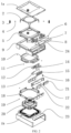
- FIG. 2 is a splitting view of a camera structure according to embodiments of this application;
- FIG. 3a is a top view of a camera structure according to embodiments of this application;
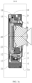
- FIG. 3b is a cross-sectional view along an A-A direction in FIG. 3a ;
- FIG. 3c is a cross-sectional view along a B-B direction in FIG. 3a ;
- FIG. 3d is a bottom view of a camera structure according to embodiments of this application.
- the camera structure provided in the embodiments of this application includes: a universal shaft 2, an outer gimbal support 9, an inner gimbal support 5 accommodated in the outer gimbal support 9, a gimbal carrier 10, a first driving mechanism 101, a second driving mechanism 102, and a camera module 103.
- the camera module 103 is movably connected to the outer gimbal support 9, and the camera module 103 is fixedly connected to the gimbal carrier 10; two supporting portions 25 of the universal shaft 2 that are axially distributed along a first axis are hinged to the outer gimbal support 9, and two supporting portions 25 of the universal shaft 2 that are axially distributed along a second axis are hinged to the inner gimbal support 5, where the first axis intersects with the second axis; and the first driving mechanism 101 is connected to the outer gimbal support 9 and the inner gimbal support 5 to drive the inner gimbal support 5 to rotate relative to the outer gimbal support 9 along the first axis and/or the second axis.
- the gimbal carrier 10 is slidably connected to a bottom portion of the inner gimbal support 5; and the second driving mechanism 102 is connected to the inner gimbal support 5 and the gimbal carrier 10, to drive the gimbal carrier 10 to rotate relative to the inner gimbal support 5 along a third axis, where the third axis is perpendicular to the first axis and the second axis.
- the first axis may extend in the same direction as an H line shown in FIG. 1
- the second axis may extend in the same direction as an M line shown in FIG. 1
- the third axis may be a Z axis shown in FIG. 1 .
- the first axis and the second axis may not be perpendicular to each other, for example: an angle between the first axis and the second axis is greater than 0° and less than 180°.
- driving the inner gimbal support 5 to rotate relative to the outer gimbal support 9 along the first axis and/or the second axis may be understood as: driving the inner gimbal support 5 to rotate relative to the outer gimbal support 9 along an X axis or a Y axis, where the outer gimbal support 9 may have a rectangular structure, with the X axis and the Y axis respectively parallel to two mutually perpendicular rectangular edges on the outer gimbal support 9.
- the inner gimbal support 5 has rotational components along the X axis direction and the Y axis direction.
- the inner gimbal support 5 also has rotational components along the X axis direction and the Y axis direction.
- the component in the Y axis direction during the rotation of the inner gimbal support 5 relative to the outer gimbal support 9 along the first axis may be offset against the component in the Y axis direction during the rotation of the inner gimbal support 5 relative to the outer gimbal support 9 along the second axis, thereby driving the inner gimbal support 5 to rotate relative to the outer gimbal support 9 along the X axis.
- That the camera module 103 is fixedly connected to the gimbal carrier 10 may be understood as that: an outer wall of the camera module 103 is attached and fixedly connected to an inner wall of the gimbal carrier 10.
- the camera structure provided in the embodiments of this application may include: a shell 1, where the shell 1 may include a top shell 1a and a bottom shell 1b, where the bottom shell 1b is recessed in a direction away from the top shell 1a to form an accommodating space between the top shell 1a and the bottom shell 1, and the universal shaft 2, the outer gimbal support 9, the inner gimbal support 5 accommodated in the outer gimbal support 9, the gimbal carrier 10, the first driving mechanism 101, the second driving mechanism 102, and the camera module 103 may be accommodated in the accommodating space of the shell 1.
- the top shell 1a, the universal shaft 2, the outer gimbal support 9, the inner gimbal support 5, and the gimbal carrier 10 are all provided with a light hole to enable the bottom camera module 103 to collect image information through the light hole. Even through the light hole, a head portion of the camera module 103 (that is, above the two axes in FIG. 1 ) is exposed to the top shell 1a.
- the camera structure provided in the embodiments of this application can be enclosed as a whole through the shell 1, and the shell 1 can also protect the camera module 103 and other components inside.
- the first driving mechanism 101 and the second driving mechanism 102 may be an electric motor driving mechanism, an electromagnetic driving mechanism, and the like.
- the following embodiments only take an example in which the first driving mechanism 101 and the second driving mechanism 102 are electromagnetic driving mechanisms for description, which is not specifically limited herein.
- Rx, Ry, and Rz respectively represent the directions of rotation along the X axis, the Y axis, and the Z axis.
- the second driving mechanism independently drives the gimbal carrier to rotate along the Rz axis direction to achieve Rz axis anti-shake, so that the Rz axis anti-shake system is independent of the Rx axis anti-shake system and Ry axis anti-shake system.
- the position feedback system of the Rz is not affected, thereby effectively improving the anti-shake accuracy of the Rz axis, more effectively improving the image quality of night shooting and video shooting when hand shaking occurs, and further enhancing the consumer experience.
- the two supporting portions 25 of the universal shaft 2 that are axially distributed along the first axis form a first rotation axis. Therefore, when the two supporting portions 25 are hinged to the outer gimbal support 9, the universal shaft 2 can rotate relative to the outer gimbal support 9 along the first rotation axis.
- the two supporting portions 25 of the universal shaft 2 that are axially distributed along the second axis form a second rotation axis.
- the universal shaft 2 can rotate relative to the inner gimbal support 5 along the second rotation axis, which enables the inner gimbal support 5 to rotate relative to the outer gimbal support 9 along the first rotation axis and the second rotation axis.
- the camera module 103 can rotate along the Rz axis direction relative to the inner gimbal support 5 through the gimbal carrier 10. Therefore, the camera module 103 rotates along the Rx axis, the Ry axis, and the Rz axis.
- shake parameters such as a shake direction and a shake distance of the camera may be obtained, and based on this, the camera structure provided in the embodiments of this application can be controlled to rotate a corresponding rotation amount along the Rx axis direction, the Ry axis direction, and the Rz axis direction to achieve anti-shake along the Rx axis direction, the Ry axis direction, and the Rz axis direction.
- FIG. 6a there is a first accommodating space 905 between a first inner side wall of the outer gimbal support 9 and a first outer side wall of the inner gimbal support 5, and the first driving mechanism 101 and the second driving mechanism 102 are disposed in the first accommodating space 905.
- the head portion of the camera module 103 can extend out of the outer gimbal support 9 through the light hole on the upper side of the outer gimbal support 9, that is, the first driving mechanism 101 and the second driving mechanism 102 can be aligned with the tail portion of the camera module 103 (that is, below the Z axis in FIG. 1 ), so that the electromagnetic driving modules of the first driving mechanism 101 and the second driving mechanism 102 can be disposed in an area that is far from the head potion of the gimbal, to provide more demagnetized areas at the head portion of the gimbal, and the camera module equipped with the gimbal can choose more types of driving motors, such as: an optical image stabilization (Optical Image Stabilization, OIS) camera module.
- OIS optical Image Stabilization
- the anti-shake function of the camera structure along the Rx direction, the Ry direction, and the Rz direction can be combined to construct a 5-axis anti-shake camera system (that is, anti-shake along the X, Y, Rx, Ry, and Rz directions), which can then drive the camera system to compensate for the shake of the 5 degrees of freedom separately or in combination, avoiding the impact of time difference and failure to switch compensation states in a timely manner in synthetic motion compensation, so that the captured images and videos have better image quality, especially in a case of shaking hands during night shooting, which can effectively improve the overall consumer experience.
- a 5-axis anti-shake camera system that is, anti-shake along the X, Y, Rx, Ry, and Rz directions
- the first driving mechanism 101 includes: a first magnet yoke 22, a first driving coil group 7, and a first magnet group 21, where
- the first direction may be in the same direction as the Y axis shown in FIG. 1
- that the first magnet group 21 matches with the first driving coil group 7 may be understood as that: the magnetic field generated by the first driving coil group 7 can act on the first magnet group 21, and a magnetic circuit is generated between the first magnet yoke 22 and the first magnet group 21, or the magnets in the first magnet group 21 correspond to the coils of the first driving coil group 7 one by one, and the corresponding magnets and coils are arranged directly facing each other.
- a current whose magnitude and direction are controllable separately can be applied to the first driving coil group 7 to generate an interaction force with a controllable direction and magnitude between the first magnet group 21 fixed to the first magnet yoke 22 and the first driving coil group 7 fixed to the outer gimbal support 9, thereby driving the first magnet yoke 22 (the first magnet group 21) to generate a rotational motion with a controllable direction along the Rx axis and the Ry axis relative to the outer gimbal support 9, thereby directly driving the inner gimbal support 5 (camera module 103) to generate rotational motion along the Rx axis and the Ry axis for anti-shake of the Rx axis and the Ry axis.
- the first magnet group 21 includes two first magnets (21A and 21B), and the first driving coil group 7 includes two first coils (7A and 7B). Therefore, the first coil 7A is arranged facing the first magnet 21A, and the first coil 7B is arranged opposite to the first magnet 21B.
- the magnet drives the inner gimbal support 5 to rotate relative to the outer gimbal support 9 along the Ry direction.
- the inner gimbal support 5 is driven to rotate relative to the outer gimbal support 9 along the Rx axis direction.
- the outer gimbal support 9 may be provided with a second through hole 903, so that the coils of the first driving coil group 7 are embedded in the second through hole 903, thereby achieving a fixed connection between the first driving coil group 7 and the outer gimbal support 9.
- first magnet yoke 22 is fixed to the first outer side wall of the inner gimbal support 5, where the first magnet yoke 22 may be directly or indirectly fixed to the first outer side wall of the inner gimbal support 5, for example: as shown in FIG. 7e , a rolling supporting bracket 18 fixed to the inner gimbal support 5 may be disposed, so that the first magnet yoke 22 is fixed to the inner gimbal support 5 through the rolling supporting bracket 18.
- the first driving coil group 7 may be connected to the first driving circuit board 601.
- the first driving circuit board 601 may be attached to the outer side of the outer gimbal support 9, and the first driving coil group 7 may be installed on the first driving circuit board 601 through the second through hole 903, to provide the current with a controllable magnitude and direction to the first driving coil group 7 through the first driving circuit board 601.
- the magnitude and direction of the current applied into the first driving coil group 7 may be controlled by a controller in the electronic device equipped with a three-axis gimbal provided in the embodiments of this application.
- a first interface 603 may also be disposed on the outer side of the first driving circuit board 601 to achieve data communication connection with the controller in the electronic device through the first interface 603.
- the first interface 603 may be connected to the first driving circuit board 601 through a connection plate 602.
- a first position feedback element group (8A and 8B) can also be disposed on the first driving circuit board 601, so that the rotation amount of the inner gimbal support 5 relative to the outer gimbal support 9 along the Rx axis direction and the Ry axis direction may be detected by the first position feedback element group (8A and 8B), thereby facilitating precise control of the rotation amount.
- the first position feedback element group 8 may be a Hall element, and may be disposed within the magnetic field range of the first magnet group 21 and the first driving coil group 7 to determine a displacement amount of the first magnet group 21 relative to the first magnet yoke 22 by inducing changes in the magnetic field, thereby determining the rotation amount of the inner gimbal support 5 relative to the outer gimbal support 9 along the Rx axis and the Ry axis.
- the first position feedback element group 8 may also be a driving chip.
- the driving chip can not only control the input of a current with a controllable magnitude and direction to the first driving coil group 7, but also feedback the rotation amount in the Rx axis direction and the Ry axis direction.
- the first driving mechanism 101 further includes: an outer magnet yoke 24, where the outer magnet yoke 24 is fixed to the outer gimbal support 9, and forms a magnetic circuit with the first magnet group 21.
- the outer magnet yoke 24 may be fixed on an outer side of the first driving circuit board 601.
- a function of the outer magnet yoke 24 is to increase the driving force of the first driving mechanism 101, in order to improve the anti-shake effect of the camera structure provided in the embodiments of this application along the Rx axis and the Ry axis.
- the second driving mechanism 102 includes: a second magnet yoke (in this implementation, the second magnet yoke and the first magnet yoke is the same magnet yoke 22), a second driving coil group 15, and a second magnet group 17, where
- the first magnet yoke and the second magnet yoke are the same magnet yoke 22, and the first magnet group 21 and the second magnet group 17 are fixed on opposite two sides of the magnet yoke 22 respectively, which can reduce a quantity of magnet yokes in the camera structure provided in the embodiments of this application, reduce its volume, and reduce costs.
- the first magnet yoke and the second magnet yoke may be different magnet yokes, which is not limited herein.
- the first magnet yoke 22 may be provided with a through hole, to engage a buckle structure 502 extending from the first outer side wall of the inner gimbal support 5 with the through hole.
- the gimbal carrier 10 is movably connected to the bottom portion of the inner gimbal support 5, so that the second driving coil group 15 fixed to the gimbal carrier 10 is located between the first outer side wall of the inner gimbal support 5 and the first magnet yoke 22.
- an interaction force may be generated between the second driving coil group 15 and the second magnet group 17 that is fixed on one side of the first magnet yoke 22 and faces towards the second driving coil group 15, thereby driving the gimbal carrier 10 relative to the inner gimbal support 5 along the third axis based on the second magnet group 17.
- the second driving coil group 15 may be connected to a second driving circuit board 13.
- the second driving circuit board may be attached to the outer side wall of the gimbal carrier 10, the second driving coil group 15 may be installed on the second driving circuit board 13, and a second driving chip 16 connected to the second driving coil group 15 may be disposed on the second driving circuit board 13, to control the magnitude and direction of the current input to the second driving coil group 15 through the second driving chip 16.
- a second position feedback element group may also be disposed on the second driving circuit board 13 (in this embodiment, the second position feedback element group and the second driving chip 16 are the same component) to obtain the rotation amount of the gimbal carrier 10 relative to the inner gimbal support 5 along the third axis through the second driving chip 16, thereby facilitating precise control of the Rz axis rotation amount.
- the second position feedback element group may also be different components from the second driving chip 16, for example, the second position feedback element group includes a Hall element, and may be disposed within the magnetic field range of the second driving coil group 15 and the second magnet group 17 to determine the displacement amount of the second driving coil group 15 relative to the second magnet yoke 22 by inducing changes in the magnetic field, thereby determining the rotation amount of the gimbal carrier 10 relative to the inner gimbal support 5 along the Rz axis direction.
- the second position feedback element group includes a Hall element, and may be disposed within the magnetic field range of the second driving coil group 15 and the second magnet group 17 to determine the displacement amount of the second driving coil group 15 relative to the second magnet yoke 22 by inducing changes in the magnetic field, thereby determining the rotation amount of the gimbal carrier 10 relative to the inner gimbal support 5 along the Rz axis direction.
- the first position feedback element group 8 may also be a driving chip.
- the driving chip can not only control the input of a current with a controllable magnitude and direction to the second driving coil group 15, but also feedback the rotation amount in the Rx axis direction and the Ry axis direction.
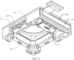
- the second driving circuit board 13 may be in a bent structure to be attached to the adjacent two side walls of the gimbal carrier 10 (for example: the first outer side wall and a bottom wall shown in FIG. 7a ).
- a circuit board stiffener 12 that matches the structure of the second driving circuit board 13 may also be disposed to enhance the structural strength of the second driving circuit board 13 by attaching the second driving circuit board 13 to the circuit board stiffener 12.
- the second driving mechanism 102 further includes: an inner magnet yoke (not shown in the figure), where the inner magnet yoke is fixed to the gimbal carrier 10, and forms a magnetic circuit with the second magnet group 17.
- the inner magnet yoke may be fixed on a side of the second driving circuit board 13 that faces away from the second driving coil group 15, for example: As shown in FIG. 7a , a groove 1004 is disposed on the outer side wall of the gimbal carrier 10 to embed the inner magnet yoke in the groove 1004 and clamp the inner magnet yoke between the gimbal carrier 10 and the second driving circuit board 13.
- a function of the inner magnet yoke 4 is to increase the driving force of the second driving mechanism 102, in order to improve the anti-shake effect of the camera structure provided in the embodiments of this application along the Rz axis direction.
- each of the supporting portions 25 is provided with a first through hole 251, and an axial direction of the first through hole 251 is perpendicular to the third axis;
- the universal shaft 2 extends along an opposite direction of the Z axis to connect to an adapter structure.
- the first ball 4 may be clamped in the first through hole 251, and then inserted into the clamping portion 3 together.
- the opposite two side walls of the clamping portion 3 may be recessed in a direction away from each other, so that when the first ball 4 is clamped in the clamping portion 3, the first ball 4 can maintain the position unchanged in the clamping portion 3.
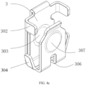
- a ball maintaining structure 303 and a ball maintaining structure 307 are respectively disposed on the opposite two side walls of the clamping portion 3, where the ball maintaining structure 307 is located on the opposite side of the ball maintaining structure 303, and the ball maintaining structure 303 is elastically connected to the side wall on which the ball maintaining structure 307 is located to facilitate the assembly of the first ball 4 and the supporting portion 25.
- the bottom portion of the clamping portion 3 is provided with an opening 306 to reduce the elastic force between the opposite two side walls of the clamping portion 3.
- the adapter structure further includes: a guide plate 302, where the guide plate 302 is fixedly connected to a first side wall of the clamping portion 3 and extends towards a direction of a second side wall of the clamping portion 3, and the first side wall of the clamping portion 3 and the second side wall of the clamping portion 3 are opposite two side walls of the clamping portion 3; and/or the adapter structure further includes: a limiting plate 304, where the limiting plate 304 is fixed on an end of the clamping portion 3 that is away from the universal shaft 2 (for example, a groove bottom portion of the U-shaped arm) to limit a rotation angle of the supporting portion 25 to be less than a preset angle in a case that the supporting portion 25 is rotated relative to the clamping portion 3.
- a guide plate 302 is fixedly connected to a first side wall of the clamping portion 3 and extends towards a direction of a second side wall of the clamping portion 3, and the first side wall of the clamping portion 3 and the second side wall of the clamping portion 3 are opposite
- the first side wall of the clamping portion 3 may be located on the side of the clamping portion 3 that is away from the center of the universal shaft 2, and a quantity of guide plates 302 is two.
- the two guide plates 302 are located on opposite two sides of the first side wall of the clamping portion 3 to align the supporting portion 25 with the center of the two guide plates 302 during assembly, thereby playing a guiding role.
- an end of the limiting plate 304 that is not fixed to the clamping portion 3 can be tilted outward, so that in a case that the supporting portion 25 is rotated by a preset angle around the first ball 4, the supporting portion 25 abuts against the limiting plate 304, thereby preventing further rotation of the supporting portion 25.
- clamping grooves (501, 901) are disposed on the outer gimbal support 9 and the inner gimbal support 5 that match the clamping portion 3.
- the clamping portion 3 is clamped in the clamping grooves (501, 901) to hinge the supporting portion 25 to the outer gimbal support 9 or the inner gimbal support 5.
- the two supporting portions 25 located on the first axis direction of the universal shaft 2 are respectively clamped in two clamping grooves 901 on the diagonal of the outer gimbal support 9, and the two supporting portions 25 located on the second axis direction of the universal shaft 2 are respectively clamped in two clamping grooves 501 on the diagonal of the inner gimbal support 5.
- clamping grooves (501, 901) are provided on the outer gimbal support 9 and the inner gimbal support 5, so that heights of the universal shaft 2, the outer gimbal support 9, and the inner gimbal support 5 along the Z axis direction can be reduced, thereby reducing the overall size of the camera structure provided in the embodiments of this application.
- the camera module 103 includes a camera component 20 and a first circuit board 23, where the camera component 20 is fixed to the gimbal carrier 10, the first circuit board 23 is fixed on a side of the camera component 20 that is away from the gimbal carrier 10, and the first circuit board 23 is movably connected to the outer gimbal support 9.
- the first circuit board 23 can transmit a data signal and an electrical signal of the camera component 20, the first circuit board 23 is fixed on a side of the camera component 20 that is away from the gimbal carrier 10, and the first circuit board 23 is movably connected to the outer gimbal support 9, so that the first circuit board 23 can rotate with the gimbal carrier 10 together.
- the first circuit board 23 includes: a first sub-circuit board 2301, a second sub-circuit board 2303, and a flexible circuit 2302, where
- the flexible circuit 2302 can form a planar spring structure to enable relative movement of the first sub-circuit board 2301 and the second sub-circuit board 2303.
- the second sub-circuit board 2303 can also be provided with an interface or a pad 2306 for connecting to a connector, and the second sub-circuit board 2303 extends from a bottom opening of the shell 1 to the outside of the shell 1, so that the pad 2306 is located outside the shell 1, so as to facilitate the connection of the first circuit board 23 with the internal circuit of the electronic device equipped with the camera structure provided in the embodiments of this application through the pad 2306.
- At least two first curved baffles 504 are disposed on the bottom portion of the inner gimbal support 5, and a ring at which the at least two first curved baffles 504 are located is coaxial with the third axis;
- the second ball 11 can only rotate around the Z axis, so that when the gimbal carrier is under stress, the gimbal carrier can only rotate around the Z axis, thereby improving the accuracy of anti-shake along the Rz axis direction.
- an end of the second curved baffle 1002 can be provided with a rotation limit portion 1003 to limit the rotation of the gimbal carrier 10 relative to the inner gimbal support 5 along the Rz axis direction.
- the camera structure further includes: a rolling supporting bracket 18, where the rolling supporting bracket 18 is fixed to the inner gimbal support 5 and abuts against a side of the gimbal carrier 10 that faces away from the inner gimbal support 5 to limit movement of the gimbal carrier 10 along a direction of the third axis.
- the gimbal carrier 10 is clamped between the rolling supporting bracket 18 and the inner gimbal support 5 to limit the axial movement of the camera module 103 along the Z axis driven by the inner gimbal support 5, thereby improving the accuracy of the camera structure.
- a groove or through hole can be provided on the bottom surface of the gimbal carrier 10 that is attached to the rolling supporting bracket 18, and the second ball 19 can be clamped in the groove or the through hole to reduce the friction between the rolling supporting bracket 18 and the gimbal carrier 10, thereby improving the sensitivity of the second driving mechanism 102 to drive the gimbal carrier 10.
- the rolling supporting bracket 18 is an integrated structure, which specifically includes: a buckle structure 1801 configured to buckle with the inner gimbal support 5, a platform 1803 configured to support the second ball 19, and an installation plate 1805 configured to fix the first magnet yoke 22.
- the installation plate 1805 is provided with a third through hole to ensure that the buckle structure on the inner gimbal support 5 passes through the third through hole and is fixedly connected to the installation plate 1805 and the first magnet yoke 22.
- the first magnet yoke 22 can be fixed to the inner gimbal support 5 by clamping between the inner gimbal support 5 and the installation plate 1805, and the installation plate 1805 is provided with a spacing portion 1808 protruding towards the direction away from the gimbal carrier 10.
- the spacing portion 1808 separates the installation plate 1805 into two parts, so that when the first magnet group 21 is installed on one side of the installation plate 1805 facing away from the gimbal carrier 10, by separating the magnets of the first magnet group 21 through the spacing portion 1808 and limiting the magnets in the first magnet group 21, the fixed strength of the magnets in the first magnet group 21 can be improved.
- the camera structure can drive the camera module to rotate in the Rx direction, the Ry direction, and the Rz direction.
- the camera structure can also be combined with corresponding algorithm processing to achieve translation shake along the X axis and the Y axis.
- the camera structure can have a total of anti-shake effect along the 5 axis direction;
- the electromagnetic driving module (the first driving mechanism and the second driving mechanism) is disposed on a side of the camera structure, which leaves more non-magnetic areas on the other three sides of the camera structure, facilitating the layout of the multi axis anti-shake mechanism;
- a planar spring circuit board structure is adopted, so that the circuit board is unfolded in a planar manner in the bottom space of the gimbal, without the need for multiple bends of the circuit board.
- the occupied space of the circuit board is reduced, the overall volume of the camera structure is reduced, and more space is allowed for layout of other devices, such as increasing battery size and capacity to improve the battery life of a mobile phone, and indirectly improving the use experience of a consumer;
- a gimbal carrier structure and a driving structure thereof that can rotate in the Rz direction are disposed in the middle of the camera structure; and movement of the gimbal carrier structure and the driving structure thereof is independent of the movement along Rx and Ry, which can effectively reduce a crosstalk impact of three-axis synchronous drive;
- the gimbal carrier 10 is provided with the second driving coil group 15 and the driving element, which can be led out through the first circuit board 23 to connect to an external circuit.
- the first driving coil group 7 and the first position feedback element group 8 are disposed on a side of the camera structure and fixed on the outer gimbal support 9, which can be directly led out to connect to the external circuit.
- a clamping portion supporting structure with double-sided clamping of the first ball 4 can reduce the impact of multi degree of freedom vibration, thereby reducing changes in camera external parameters and providing strong support for multi camera fusion algorithms.
- An embodiment of this application further provides an electronic device, and the electronic device includes any camera structure shown in FIG. 1 to FIG. 8b .
- the electronic device in the embodiments of this application may be a mobile electronic device or may be a non-mobile electronic device.
- the mobile electronic device may be a mobile phone, a tablet computer, a notebook computer, a palm computer, an in-vehicle electronic device, a wearable device, an ultra-mobile personal computer (ultra-mobile personal computer, UMPC), a netbook, or a personal digital assistant (personal digital assistant, PDA), and the non-mobile electronic device may be a personal computer (personal computer, PC), a television (television, TV), a teller machine, or an automated machine, which are not specifically limited in the embodiments of this application.
- the electronic device provided in embodiments of this application includes any camera structure shown in FIG. 1 to FIG. 8b , and has the same beneficial effect as any camera structure shown in FIG. 1 to FIG. 8b . To avoid repetition, it will not be repeated here.
Landscapes
- Engineering & Computer Science (AREA)
- Multimedia (AREA)
- Signal Processing (AREA)
- Physics & Mathematics (AREA)
- General Physics & Mathematics (AREA)
- Accessories Of Cameras (AREA)
- Studio Devices (AREA)
- Adjustment Of Camera Lenses (AREA)
Abstract
Description
- This application claims priority to
Chinese Patent Application No. 202110417591.2 filed on April 19, 2021 - This application relates to the field of camera technologies, and specifically, to a camera structure and an electronic device.
- With the continuous development of electronic devices, requirements of people for the shooting performance of the electronic devices are becoming higher and higher. The application of micro gimbals on the electronic devices has greatly improved the experience of consumers in improving the quality of handheld photography. Generally, a shaking amount corresponding to hand shaking can be decomposed into three directions X, Y, and Z in space, with a total of 6 degrees of freedom (movement along an X/Y/Z axis and rotation around the X/Y/Z axis: Rx, Ry, Rz). In addition to axial shaking in a focusing direction (Z axis), the shaking of the other 5 degrees of freedom has a significant impact on handheld photography, especially for night shooting and video shooting, ultimately affecting the imaging effect and consumer experience. At present, micro gimbal cameras used in the electronic devices (such as mobile phones) are two-axis gimbals, which can only prevent shaking of 4 degrees of freedom and cannot prevent shaking (Rz) rotating along the Z axis. Therefore, when there is shaking in the Rz direction, the imaging quality of the micro gimbal cameras is poor.
- It can be seen that the anti-shake effect of the micro gimbal cameras in related technologies is poor.
- Embodiments of this application aim to provide a camera structure that can solve the problem of a poor anti-shake effect of a micro gimbal camera in related technologies.
- To resolve the foregoing technical problems, this application is implemented as follows:
- According to a first aspect, an embodiment of this application provides a camera structure, including a universal shaft, an outer gimbal support, an inner gimbal support accommodated in the outer gimbal support, a gimbal carrier, a first driving mechanism, a second driving mechanism, and a camera module, where
- the camera module is movably connected to the outer gimbal support, and the camera module is fixedly connected to the gimbal carrier;
- two supporting portions of the universal shaft that are axially distributed along a first axis are hinged to the outer gimbal support, and two supporting portions of the universal shaft that are axially distributed along a second axis are hinged to the inner gimbal support, where the first axis intersects with the second axis;
- the first driving mechanism is connected to the outer gimbal support and the inner gimbal support, to drive the inner gimbal support to rotate relative to the outer gimbal support along the first axis and/or the second axis;
- the gimbal carrier is slidably connected to a bottom portion of the inner gimbal support; and
- the second driving mechanism is connected to the inner gimbal support and the gimbal carrier, to drive the gimbal carrier to rotate relative to the inner gimbal support along a third axis, where the third axis is perpendicular to the first axis and the second axis.
- Optionally, there is a first accommodating space between a first inner side wall of the outer gimbal support and a first outer side wall of the inner gimbal support, and the first driving mechanism and the second driving mechanism are disposed in the first accommodating space.
- Optionally, the first driving mechanism includes: a first magnet yoke, a first driving coil group, and a first magnet group, where
- the first driving coil group is fixed to the outer gimbal support, the first magnet yoke is fixed to the first outer side wall of the inner gimbal support, the first magnet group is fixed to the first magnet yoke, and the first magnet group matches with the first driving coil group; and
- at least two coils of the first driving coil group are arranged at interval along a first direction, the first direction is perpendicular to the third axis, the first driving coil group is distributed on two opposite sides of a symmetry axis of the inner gimbal support, and the symmetry axis is in a same direction as a direction from the first outer side wall of the inner gimbal support to the first inner side wall of the outer gimbal support, where
- in a case that the first driving coil group is energized with current, an interaction force is generated between the first driving coil group and the first magnet group, and the first magnet group drives, based on the interaction force, the inner gimbal support to rotate relative to the outer gimbal support along the first axis and/or along the second axis.
- Optionally, the camera structure further includes:
a first position feedback element group, configured to detect a rotation amount of the inner gimbal support relative to the outer gimbal support along the first axis or the second axis, where the first position feedback element group is disposed within a magnetic field range of the first magnet group and the first driving coil group. - Optionally, the first driving mechanism further includes: an outer magnet yoke, where
the outer magnet yoke is fixed to the outer gimbal support, and forms a magnetic circuit with the first magnet group. - Optionally, the second driving mechanism includes: a second magnet yoke, a second driving coil group, and a second magnet group, where
- the second driving coil group is fixed to the gimbal carrier, the second magnet yoke is fixed to the first outer side wall of the inner gimbal support, the second magnet group is fixed to the second magnet yoke, and the second magnet group matches with the second driving coil group; and
- at least two coils of the second driving coil group are arranged at interval along a first direction, the first direction is perpendicular to the third axis, the second driving coil group is distributed on two opposite sides of a symmetry axis of the gimbal carrier, and the symmetry axis is in a same direction as a direction from the first outer side wall of the inner gimbal support to the first inner side wall of the outer gimbal support, where
- in a case that the second driving coil group is energized with current, an interaction force is generated between the second driving coil group and the second magnet group, and the second magnet group drives, based on the interaction force, the gimbal carrier to rotate relative to the inner gimbal support along the third axis.
- Optionally, the camera structure further includes:
a second position feedback element group, configured to detect a rotation amount of the gimbal carrier relative to the inner gimbal support along the third axis, where the second position feedback element group is disposed within a magnetic field range of the second magnet group and the second driving coil group. - Optionally, the first driving mechanism further includes: an inner magnet yoke, where
the inner magnet yoke is fixed to the gimbal carrier, and forms a magnetic circuit with the second magnet group. - Optionally, each of the supporting portions is provided with a first through hole, and an axial direction of the first through hole is perpendicular to the third axis; and
- the camera structure further includes: an adapter structure, where the adapter structure includes a clamping portion and a first ball, where
- the first ball is disposed inside the first through hole and is clamped between two side walls of the clamping portion; and
- the clamping portion is configured to be fixedly connected to the outer gimbal support or the inner gimbal support.
- Optionally, the adapter structure further includes: a guide plate, where the guide plate is fixedly connected to a first side wall of the clamping portion and extends towards a direction of a second side wall of the clamping portion, and the first side wall of the clamping portion and the second side wall of the clamping portion are opposite two side walls of the clamping portion;
and/or
the adapter structure further includes: a limiting plate, where the limiting plate is fixed at a groove bottom of the clamping portion to limit a rotation angle of the supporting portion to be less than a preset angle in a case that the supporting portion is rotated relative to the clamping portion. - Optionally, the outer gimbal support and the inner gimbal support are provided with clamping grooves that matches the clamping portion, and the clamping portion is clamped in the clamping grooves to hinge the supporting portion to the outer gimbal support or the inner gimbal support.
- Optionally, the camera module includes a camera component and a first circuit board, where
the camera component is fixed to the gimbal carrier, the first circuit board is fixed on a side of the camera component that is away from the gimbal carrier, and the first circuit board is movably connected to the outer gimbal support. - Optionally, the first circuit board includes: a first sub-circuit board, a second sub-circuit board, and a flexible circuit, where
- the second sub-circuit board surrounds the first sub-circuit board, and the first sub-circuit board and the second sub-circuit board are located in a same plane; and
- the first sub-circuit board is movably connected to the second sub-circuit board through the flexible circuit.
- Optionally, at least two first curved baffles are disposed on the bottom portion of the inner gimbal support, and a ring at which the at least two first curved baffles are located is coaxial with the third axis; and
- at least two second curved baffles that are in a one-to-one correspondence with the at least two first curved baffles are disposed on the gimbal carrier, and one first curved baffle and one second curved baffle form a curved baffle group; and
- the camera structure further includes: a second ball, where
- one second ball is clamped in one curved baffle group.
- Optionally, the camera structure further includes: a rolling supporting bracket, where
the rolling supporting bracket is fixed to the inner gimbal support and abuts against a side of the gimbal carrier that faces away from the inner gimbal support to limit movement of the gimbal carrier along a direction of the third axis. - According to a second aspect, an embodiment of this application provides an electronic device, and the electronic device includes the camera structure according to the first aspect.
- In the embodiments of this application, the camera structure includes: a universal shaft, an outer gimbal support, an inner gimbal support accommodated in the outer gimbal support, a gimbal carrier, a first driving mechanism, a second driving mechanism, and a camera module, where the camera module is movably connected to the outer gimbal support, and the camera module is fixedly connected to the gimbal carrier; two supporting portions of the universal shaft that are axially distributed along a first axis are hinged to the outer gimbal support, and two supporting portions of the universal shaft that are axially distributed along a second axis are hinged to the inner gimbal support, where the first axis intersects with the second axis; the first driving mechanism is connected to the outer gimbal support and the inner gimbal support, to drive the inner gimbal support to rotate relative to the outer gimbal support along the first axis and/or the second axis; the gimbal carrier is slidably connected to a bottom portion of the inner gimbal support; and the second driving mechanism is connected to the inner gimbal support and the gimbal carrier, to drive the gimbal carrier to rotate relative to the inner gimbal support along a third axis, where the third axis is perpendicular to the first axis and the second axis. In this way, the camera module can rotate relative to the outer gimbal support along the first axis, the second axis, or the third axis, to enhance the freedom of the camera module, thereby enhancing the anti-shake effect of the camera.
-
-
FIG. 1 is a side view of a camera structure according to embodiments of this application; -
FIG. 2 is a splitting view of a camera structure according to embodiments of this application; -
FIG. 3a is a top view of a camera structure according to embodiments of this application; -
FIG. 3b is a cross-sectional view along an A-A direction inFIG. 3a ; -
FIG. 3c is a cross-sectional view along a B-B direction inFIG. 3a ; -
FIG. 3d is a bottom view of a camera structure according to embodiments of this application; -
FIG. 4a is a structural diagram of a universal shaft; -
FIG. 4b is a structural diagram of assembly of a universal shaft and an adapter structure; -
FIG. 4c is a side view of an adapter structure; -
FIG. 4d is a main view of an adapter structure; -
FIG. 4e is a cross-sectional view along a C-C direction inFIG. 4d ; -
FIG. 5 is a structural diagram of assembly of a universal shaft, an inner gimbal support, an adapter structure, a second magnet yoke, a first magnet group, and a second magnet group; -
FIG. 6a is an assembly diagram of a universal shaft, an outer gimbal support, and inner gimbal support; -
FIG. 6b is a disassembly diagram of a first driving coil group; -
FIG. 7a is a structural diagram of assembly of a gimbal carrier and a second driving coil group; -
FIG. 7b is a bottom view of an inner gimbal support; -
FIG. 7c is a structural diagram of assembly of a gimbal carrier, an inner gimbal support, and an outer gimbal support; -
FIG. 7d is a structural diagram of assembly of a gimbal carrier and an inner gimbal support; -
FIG. 7e is a structural diagram of assembly of a gimbal carrier, an inner gimbal support, and a rotating carrier; -
FIG. 8a is a structural diagram of a flexible circuit board; and -
FIG. 8b is a structural diagram of assembly of a flexible circuit board and a camera component. - The following clearly and completely describes the technical solutions in the embodiments of this application with reference to the accompanying drawings in the embodiments of this application. Apparently, the described embodiments are some of the embodiments of this application rather than all of the embodiments. All other embodiments obtained by a person of ordinary skill in the art based on the embodiments of this application without creative efforts shall fall within the protection scope of this application.
- The specification and claims of this application, and terms "first" and "second" are used to distinguish similar objects, but are unnecessarily used to describe a specific sequence or order. It should be understood that the data in such a way are interchangeable in proper circumstances, so that the embodiments of this application can be implemented in other orders than the order illustrated or described herein. Objects distinguished by "first", "second", and the like are usually one type, and the number of objects is not limited. For example, the first object may be one or more than one. In addition, in the specification and the claims, "and/or" means at least one of the connected objects, and the character "/" generally indicates an "or" relationship between the associated objects.
- A camera structure and an electronic device provided in the embodiments of this application are described below through specific embodiments and application scenarios thereof with reference to the accompanying drawings.
- Refer to
FIG. 1 to FIG. 3d .FIG. 1 is a structural diagram of a camera structure according to embodiments of this application;FIG. 2 is a splitting view of a camera structure according to embodiments of this application;FIG. 3a is a top view of a camera structure according to embodiments of this application;FIG. 3b is a cross-sectional view along an A-A direction inFIG. 3a ;FIG. 3c is a cross-sectional view along a B-B direction inFIG. 3a ;FIG. 3d is a bottom view of a camera structure according to embodiments of this application. The camera structure provided in the embodiments of this application includes: auniversal shaft 2, anouter gimbal support 9, aninner gimbal support 5 accommodated in theouter gimbal support 9, agimbal carrier 10, afirst driving mechanism 101, asecond driving mechanism 102, and acamera module 103. - The
camera module 103 is movably connected to theouter gimbal support 9, and thecamera module 103 is fixedly connected to thegimbal carrier 10; two supportingportions 25 of theuniversal shaft 2 that are axially distributed along a first axis are hinged to theouter gimbal support 9, and two supportingportions 25 of theuniversal shaft 2 that are axially distributed along a second axis are hinged to theinner gimbal support 5, where the first axis intersects with the second axis; and thefirst driving mechanism 101 is connected to theouter gimbal support 9 and theinner gimbal support 5 to drive theinner gimbal support 5 to rotate relative to theouter gimbal support 9 along the first axis and/or the second axis. - In addition, the
gimbal carrier 10 is slidably connected to a bottom portion of theinner gimbal support 5; and thesecond driving mechanism 102 is connected to theinner gimbal support 5 and thegimbal carrier 10, to drive thegimbal carrier 10 to rotate relative to theinner gimbal support 5 along a third axis, where the third axis is perpendicular to the first axis and the second axis. - In a specific implementation, the first axis may extend in the same direction as an H line shown in
FIG. 1 , the second axis may extend in the same direction as an M line shown inFIG. 1 , and the third axis may be a Z axis shown inFIG. 1 . Certainly, in a practical application, the first axis and the second axis may not be perpendicular to each other, for example: an angle between the first axis and the second axis is greater than 0° and less than 180°. - In an implementation, driving the
inner gimbal support 5 to rotate relative to theouter gimbal support 9 along the first axis and/or the second axis may be understood as: driving theinner gimbal support 5 to rotate relative to theouter gimbal support 9 along an X axis or a Y axis, where theouter gimbal support 9 may have a rectangular structure, with the X axis and the Y axis respectively parallel to two mutually perpendicular rectangular edges on theouter gimbal support 9. - Specifically, during the rotation of the
inner gimbal support 5 relative to theouter gimbal support 9 along the first axis, theinner gimbal support 5 has rotational components along the X axis direction and the Y axis direction. Similarly, during the rotation of theinner gimbal support 5 relative to theouter gimbal support 9 along the second axis, theinner gimbal support 5 also has rotational components along the X axis direction and the Y axis direction. In this case, if only theinner gimbal support 5 needs to be driven to rotate relative to theouter gimbal support 9 along the X axis, the component in the Y axis direction during the rotation of theinner gimbal support 5 relative to theouter gimbal support 9 along the first axis may be offset against the component in the Y axis direction during the rotation of theinner gimbal support 5 relative to theouter gimbal support 9 along the second axis, thereby driving theinner gimbal support 5 to rotate relative to theouter gimbal support 9 along the X axis. - That the
camera module 103 is fixedly connected to thegimbal carrier 10 may be understood as that: an outer wall of thecamera module 103 is attached and fixedly connected to an inner wall of thegimbal carrier 10. - In a practical application, as shown in
FIG. 1 andFIG. 2 , the camera structure provided in the embodiments of this application may include: ashell 1, where theshell 1 may include a top shell 1a and abottom shell 1b, where thebottom shell 1b is recessed in a direction away from the top shell 1a to form an accommodating space between the top shell 1a and thebottom shell 1, and theuniversal shaft 2, theouter gimbal support 9, theinner gimbal support 5 accommodated in theouter gimbal support 9, thegimbal carrier 10, thefirst driving mechanism 101, thesecond driving mechanism 102, and thecamera module 103 may be accommodated in the accommodating space of theshell 1. In addition, the top shell 1a, theuniversal shaft 2, theouter gimbal support 9, theinner gimbal support 5, and thegimbal carrier 10 are all provided with a light hole to enable thebottom camera module 103 to collect image information through the light hole. Even through the light hole, a head portion of the camera module 103 (that is, above the two axes inFIG. 1 ) is exposed to the top shell 1a. - In this way, the camera structure provided in the embodiments of this application can be enclosed as a whole through the
shell 1, and theshell 1 can also protect thecamera module 103 and other components inside. - In a specific implementation, the
first driving mechanism 101 and thesecond driving mechanism 102 may be an electric motor driving mechanism, an electromagnetic driving mechanism, and the like. For the convenience of description, the following embodiments only take an example in which thefirst driving mechanism 101 and thesecond driving mechanism 102 are electromagnetic driving mechanisms for description, which is not specifically limited herein. - In addition, in the coordinate axis shown in
FIG. 1 , Rx, Ry, and Rz respectively represent the directions of rotation along the X axis, the Y axis, and the Z axis. - In the embodiments of this application, the second driving mechanism independently drives the gimbal carrier to rotate along the Rz axis direction to achieve Rz axis anti-shake, so that the Rz axis anti-shake system is independent of the Rx axis anti-shake system and Ry axis anti-shake system. In this way, when anti-shake functions are performed on the Rx axis or the Ry axis, the position feedback system of the Rz is not affected, thereby effectively improving the anti-shake accuracy of the Rz axis, more effectively improving the image quality of night shooting and video shooting when hand shaking occurs, and further enhancing the consumer experience.
- In addition, that two supporting
portions 25 of theuniversal shaft 2 that are axially distributed along a first axis are hinged to theouter gimbal support 9, and two supportingportions 25 of theuniversal shaft 2 that are axially distributed along a second axis are hinged to theinner gimbal support 5 may be understood as that: The two supportingportions 25 of theuniversal shaft 2 that are axially distributed along the first axis form a first rotation axis. Therefore, when the two supportingportions 25 are hinged to theouter gimbal support 9, theuniversal shaft 2 can rotate relative to theouter gimbal support 9 along the first rotation axis. And the two supportingportions 25 of theuniversal shaft 2 that are axially distributed along the second axis form a second rotation axis. Therefore, when the two supportingportions 25 are hinged to theinner gimbal support 5, theuniversal shaft 2 can rotate relative to theinner gimbal support 5 along the second rotation axis, which enables theinner gimbal support 5 to rotate relative to theouter gimbal support 9 along the first rotation axis and the second rotation axis. - On this basis, the
camera module 103 can rotate along the Rz axis direction relative to theinner gimbal support 5 through thegimbal carrier 10. Therefore, thecamera module 103 rotates along the Rx axis, the Ry axis, and the Rz axis. In an actual shooting, shake parameters such as a shake direction and a shake distance of the camera may be obtained, and based on this, the camera structure provided in the embodiments of this application can be controlled to rotate a corresponding rotation amount along the Rx axis direction, the Ry axis direction, and the Rz axis direction to achieve anti-shake along the Rx axis direction, the Ry axis direction, and the Rz axis direction. - Optionally, as shown in
FIG. 6a , there is a first accommodating space 905 between a first inner side wall of theouter gimbal support 9 and a first outer side wall of theinner gimbal support 5, and thefirst driving mechanism 101 and thesecond driving mechanism 102 are disposed in the first accommodating space 905. - In a specific implementation, the head portion of the
camera module 103 can extend out of theouter gimbal support 9 through the light hole on the upper side of theouter gimbal support 9, that is, thefirst driving mechanism 101 and thesecond driving mechanism 102 can be aligned with the tail portion of the camera module 103 (that is, below the Z axis inFIG. 1 ), so that the electromagnetic driving modules of thefirst driving mechanism 101 and thesecond driving mechanism 102 can be disposed in an area that is far from the head potion of the gimbal, to provide more demagnetized areas at the head portion of the gimbal, and the camera module equipped with the gimbal can choose more types of driving motors, such as: an optical image stabilization (Optical Image Stabilization, OIS) camera module. In this way, the anti-shake function of the camera structure along the Rx direction, the Ry direction, and the Rz direction provided in the embodiments of this application can be combined to construct a 5-axis anti-shake camera system (that is, anti-shake along the X, Y, Rx, Ry, and Rz directions), which can then drive the camera system to compensate for the shake of the 5 degrees of freedom separately or in combination, avoiding the impact of time difference and failure to switch compensation states in a timely manner in synthetic motion compensation, so that the captured images and videos have better image quality, especially in a case of shaking hands during night shooting, which can effectively improve the overall consumer experience. - Optionally, as shown in
FIG. 2 andFIG 3b , thefirst driving mechanism 101 includes: afirst magnet yoke 22, a firstdriving coil group 7, and afirst magnet group 21, where - the first
driving coil group 7 is fixed to theouter gimbal support 9, thefirst magnet yoke 22 is fixed to the first outer side wall of theinner gimbal support 5, thefirst magnet group 21 is fixed to thefirst magnet yoke 22, and thefirst magnet group 21 matches with the firstdriving coil group 7; and - at least two coils of the first
driving coil group 7 are arranged at interval along a first direction, the first direction is perpendicular to the third axis (Z axis), the firstdriving coil group 7 is distributed on two opposite sides of a symmetry axis of theinner gimbal support 5, and the symmetry axis is in a same direction as a direction from the first outer side wall of theinner gimbal support 5 to the first inner side wall of theouter gimbal support 9, where - in a case that the first
driving coil group 7 is energized with current, an interaction force is generated between the firstdriving coil group 7 and thefirst magnet group 21, and thefirst magnet group 21 drives, based on the interaction force, theinner gimbal support 5 to rotate relative to theouter gimbal support 9 along the first axis and/or along the second axis (or may be understood as that: the firstdriving coil group 7 drives theinner gimbal support 5 to rotate relative to theouter gimbal support 9 along the first axis and/or along the second axis based on the interaction force). - In a specific implementation, the first direction may be in the same direction as the Y axis shown in
FIG. 1 , and that thefirst magnet group 21 matches with the firstdriving coil group 7 may be understood as that: the magnetic field generated by the firstdriving coil group 7 can act on thefirst magnet group 21, and a magnetic circuit is generated between thefirst magnet yoke 22 and thefirst magnet group 21, or the magnets in thefirst magnet group 21 correspond to the coils of the firstdriving coil group 7 one by one, and the corresponding magnets and coils are arranged directly facing each other. - In an implementation, a current whose magnitude and direction are controllable separately can be applied to the first
driving coil group 7 to generate an interaction force with a controllable direction and magnitude between thefirst magnet group 21 fixed to thefirst magnet yoke 22 and the firstdriving coil group 7 fixed to theouter gimbal support 9, thereby driving the first magnet yoke 22 (the first magnet group 21) to generate a rotational motion with a controllable direction along the Rx axis and the Ry axis relative to theouter gimbal support 9, thereby directly driving the inner gimbal support 5 (camera module 103) to generate rotational motion along the Rx axis and the Ry axis for anti-shake of the Rx axis and the Ry axis. - Specifically, as shown in
FIG. 5 andFIG. 6b , thefirst magnet group 21 includes two first magnets (21A and 21B), and the firstdriving coil group 7 includes two first coils (7A and 7B). Therefore, thefirst coil 7A is arranged facing the first magnet 21A, and thefirst coil 7B is arranged opposite to the first magnet 21B. In a case that the force directions of the first magnet 21A and the first magnet 21B are in the same direction as the Z axis or in the same direction as the -Z axis, the magnet drives theinner gimbal support 5 to rotate relative to theouter gimbal support 9 along the Ry direction. When the force directions of the first magnet 21A and the first magnet 21B are different, that is, one is in the same direction as the Z axis and the other is in the same direction as the -Z axis, theinner gimbal support 5 is driven to rotate relative to theouter gimbal support 9 along the Rx axis direction. - In a specific implementation, the
outer gimbal support 9 may be provided with a second throughhole 903, so that the coils of the firstdriving coil group 7 are embedded in the second throughhole 903, thereby achieving a fixed connection between the firstdriving coil group 7 and theouter gimbal support 9. - In addition, the
first magnet yoke 22 is fixed to the first outer side wall of theinner gimbal support 5, where thefirst magnet yoke 22 may be directly or indirectly fixed to the first outer side wall of theinner gimbal support 5, for example: as shown inFIG. 7e , a rolling supportingbracket 18 fixed to theinner gimbal support 5 may be disposed, so that thefirst magnet yoke 22 is fixed to theinner gimbal support 5 through the rolling supportingbracket 18. - Further, in order to apply a current with a controllable magnitude and direction to the first
driving coil group 7, the firstdriving coil group 7 may be connected to the firstdriving circuit board 601. The firstdriving circuit board 601 may be attached to the outer side of theouter gimbal support 9, and the firstdriving coil group 7 may be installed on the firstdriving circuit board 601 through the second throughhole 903, to provide the current with a controllable magnitude and direction to the firstdriving coil group 7 through the firstdriving circuit board 601. - In an implementation, the magnitude and direction of the current applied into the first
driving coil group 7 may be controlled by a controller in the electronic device equipped with a three-axis gimbal provided in the embodiments of this application. In this case, afirst interface 603 may also be disposed on the outer side of the firstdriving circuit board 601 to achieve data communication connection with the controller in the electronic device through thefirst interface 603. Specifically, as shown inFIG. 6b , thefirst interface 603 may be connected to the firstdriving circuit board 601 through aconnection plate 602. - In addition, in a practical application, a first position feedback element group (8A and 8B) can also be disposed on the first
driving circuit board 601, so that the rotation amount of theinner gimbal support 5 relative to theouter gimbal support 9 along the Rx axis direction and the Ry axis direction may be detected by the first position feedback element group (8A and 8B), thereby facilitating precise control of the rotation amount. - In an implementation, as shown in
FIG. 6b , the first position feedback element group 8 may be a Hall element, and may be disposed within the magnetic field range of thefirst magnet group 21 and the firstdriving coil group 7 to determine a displacement amount of thefirst magnet group 21 relative to thefirst magnet yoke 22 by inducing changes in the magnetic field, thereby determining the rotation amount of theinner gimbal support 5 relative to theouter gimbal support 9 along the Rx axis and the Ry axis. - Certainly, in a specific implementation, the first position feedback element group 8 may also be a driving chip. The driving chip can not only control the input of a current with a controllable magnitude and direction to the first
driving coil group 7, but also feedback the rotation amount in the Rx axis direction and the Ry axis direction. - Optionally, the
first driving mechanism 101 further includes: anouter magnet yoke 24, where theouter magnet yoke 24 is fixed to theouter gimbal support 9, and forms a magnetic circuit with thefirst magnet group 21. - In an implementation, as shown in
FIG. 6b , theouter magnet yoke 24 may be fixed on an outer side of the firstdriving circuit board 601. - A function of the
outer magnet yoke 24 is to increase the driving force of thefirst driving mechanism 101, in order to improve the anti-shake effect of the camera structure provided in the embodiments of this application along the Rx axis and the Ry axis. - Optionally, the
second driving mechanism 102 includes: a second magnet yoke (in this implementation, the second magnet yoke and the first magnet yoke is the same magnet yoke 22), a seconddriving coil group 15, and asecond magnet group 17, where - the second
driving coil group 15 is fixed to thegimbal carrier 10, thesecond magnet yoke 22 is fixed to the first outer side wall of theinner gimbal support 5, thesecond magnet group 17 is fixed to thesecond magnet yoke 22, and thesecond magnet group 17 matches with the seconddriving coil group 15; and - at least two coils of the second
driving coil group 15 are arranged at interval along a first direction, the first direction is perpendicular to the third axis, the seconddriving coil group 15 is distributed on two opposite sides of a symmetry axis of thegimbal carrier 10, and the symmetry axis is in a same direction as a direction from the first outer side wall of theinner gimbal support 5 to the first inner side wall of theouter gimbal support 9, where - in a case that the second
driving coil group 15 is energized with current, an interaction force is generated between the seconddriving coil group 15 and thesecond magnet group 17, and thesecond magnet group 17 drives, based on the interaction force, thegimbal carrier 10 to rotate relative to theinner gimbal support 5 along the third axis. - It should be noted that in the embodiments of this application, the first magnet yoke and the second magnet yoke are the
same magnet yoke 22, and thefirst magnet group 21 and thesecond magnet group 17 are fixed on opposite two sides of themagnet yoke 22 respectively, which can reduce a quantity of magnet yokes in the camera structure provided in the embodiments of this application, reduce its volume, and reduce costs. Certainly, if space and cost allow, the first magnet yoke and the second magnet yoke may be different magnet yokes, which is not limited herein. - In an implementation, as shown in
FIG. 7b , thefirst magnet yoke 22 may be provided with a through hole, to engage abuckle structure 502 extending from the first outer side wall of theinner gimbal support 5 with the through hole. In addition, thegimbal carrier 10 is movably connected to the bottom portion of theinner gimbal support 5, so that the seconddriving coil group 15 fixed to thegimbal carrier 10 is located between the first outer side wall of theinner gimbal support 5 and thefirst magnet yoke 22. Therefore, when the seconddriving coil group 15 is energized with a current with a controlled magnitude and direction, an interaction force may be generated between the seconddriving coil group 15 and thesecond magnet group 17 that is fixed on one side of thefirst magnet yoke 22 and faces towards the seconddriving coil group 15, thereby driving thegimbal carrier 10 relative to theinner gimbal support 5 along the third axis based on thesecond magnet group 17. - Further, in order to apply a current with a controllable magnitude and direction to the second
driving coil group 15, the seconddriving coil group 15 may be connected to a seconddriving circuit board 13. The second driving circuit board may be attached to the outer side wall of thegimbal carrier 10, the seconddriving coil group 15 may be installed on the seconddriving circuit board 13, and asecond driving chip 16 connected to the seconddriving coil group 15 may be disposed on the seconddriving circuit board 13, to control the magnitude and direction of the current input to the seconddriving coil group 15 through thesecond driving chip 16. - In addition, in a practical application, a second position feedback element group may also be disposed on the second driving circuit board 13 (in this embodiment, the second position feedback element group and the
second driving chip 16 are the same component) to obtain the rotation amount of thegimbal carrier 10 relative to theinner gimbal support 5 along the third axis through thesecond driving chip 16, thereby facilitating precise control of the Rz axis rotation amount. - Certainly, in a specific implementation, the second position feedback element group may also be different components from the
second driving chip 16, for example, the second position feedback element group includes a Hall element, and may be disposed within the magnetic field range of the seconddriving coil group 15 and thesecond magnet group 17 to determine the displacement amount of the seconddriving coil group 15 relative to thesecond magnet yoke 22 by inducing changes in the magnetic field, thereby determining the rotation amount of thegimbal carrier 10 relative to theinner gimbal support 5 along the Rz axis direction. - In addition, in a specific implementation, the first position feedback element group 8 may also be a driving chip. The driving chip can not only control the input of a current with a controllable magnitude and direction to the second
driving coil group 15, but also feedback the rotation amount in the Rx axis direction and the Ry axis direction. - Further, as shown in
FIG. 7a , the seconddriving circuit board 13 may be in a bent structure to be attached to the adjacent two side walls of the gimbal carrier 10 (for example: the first outer side wall and a bottom wall shown inFIG. 7a ). In addition, acircuit board stiffener 12 that matches the structure of the seconddriving circuit board 13 may also be disposed to enhance the structural strength of the seconddriving circuit board 13 by attaching the seconddriving circuit board 13 to thecircuit board stiffener 12. - Optionally, the
second driving mechanism 102 further includes: an inner magnet yoke (not shown in the figure), where the inner magnet yoke is fixed to thegimbal carrier 10, and forms a magnetic circuit with thesecond magnet group 17. - In an implementation, the inner magnet yoke may be fixed on a side of the second
driving circuit board 13 that faces away from the seconddriving coil group 15, for example: As shown inFIG. 7a , a groove 1004 is disposed on the outer side wall of thegimbal carrier 10 to embed the inner magnet yoke in the groove 1004 and clamp the inner magnet yoke between thegimbal carrier 10 and the seconddriving circuit board 13. - A function of the
inner magnet yoke 4 is to increase the driving force of thesecond driving mechanism 102, in order to improve the anti-shake effect of the camera structure provided in the embodiments of this application along the Rz axis direction. - Optionally, as shown in
FIG. 4a andFIG. 4b , each of the supportingportions 25 is provided with a first throughhole 251, and an axial direction of the first throughhole 251 is perpendicular to the third axis; and - the camera structure further includes: an adapter structure, where the adapter structure includes a clamping portion 3 (for example, a U-shaped arm) and a
first ball 4, wherein - the
first ball 4 is disposed inside the first throughhole 251 and is clamped between two side walls of the clampingportion 3; and - the clamping
portion 3 is configured to be fixedly connected to theouter gimbal support 9 or theinner gimbal support 5. - As shown in
FIG. 4a , four corners of theuniversal shaft 2 extend along an opposite direction of the Z axis to connect to an adapter structure. During the assembly process, thefirst ball 4 may be clamped in the first throughhole 251, and then inserted into the clampingportion 3 together. - In addition, as shown in
FIG. 4c , the opposite two side walls of the clampingportion 3 may be recessed in a direction away from each other, so that when thefirst ball 4 is clamped in the clampingportion 3, thefirst ball 4 can maintain the position unchanged in the clampingportion 3. Specifically, aball maintaining structure 303 and aball maintaining structure 307 are respectively disposed on the opposite two side walls of the clampingportion 3, where theball maintaining structure 307 is located on the opposite side of theball maintaining structure 303, and theball maintaining structure 303 is elastically connected to the side wall on which theball maintaining structure 307 is located to facilitate the assembly of thefirst ball 4 and the supportingportion 25. The bottom portion of the clampingportion 3 is provided with anopening 306 to reduce the elastic force between the opposite two side walls of the clampingportion 3. - Further, as shown in
FIG. 4c ,FIG. 4d , andFIG. 4e , the adapter structure further includes: aguide plate 302, where theguide plate 302 is fixedly connected to a first side wall of the clampingportion 3 and extends towards a direction of a second side wall of the clampingportion 3, and the first side wall of the clampingportion 3 and the second side wall of the clampingportion 3 are opposite two side walls of the clampingportion 3;
and/or
the adapter structure further includes: a limitingplate 304, where the limitingplate 304 is fixed on an end of the clampingportion 3 that is away from the universal shaft 2 (for example, a groove bottom portion of the U-shaped arm) to limit a rotation angle of the supportingportion 25 to be less than a preset angle in a case that the supportingportion 25 is rotated relative to the clampingportion 3. - In an implementation, the first side wall of the clamping
portion 3 may be located on the side of the clampingportion 3 that is away from the center of theuniversal shaft 2, and a quantity ofguide plates 302 is two. The twoguide plates 302 are located on opposite two sides of the first side wall of the clampingportion 3 to align the supportingportion 25 with the center of the twoguide plates 302 during assembly, thereby playing a guiding role. - In addition, an end of the limiting
plate 304 that is not fixed to the clampingportion 3 can be tilted outward, so that in a case that the supportingportion 25 is rotated by a preset angle around thefirst ball 4, the supportingportion 25 abuts against the limitingplate 304, thereby preventing further rotation of the supportingportion 25. - Optionally, as shown in
FIG. 5 andFIG. 6a , clamping grooves (501, 901) are disposed on theouter gimbal support 9 and theinner gimbal support 5 that match the clampingportion 3. The clampingportion 3 is clamped in the clamping grooves (501, 901) to hinge the supportingportion 25 to theouter gimbal support 9 or theinner gimbal support 5. - Specifically, the two supporting
portions 25 located on the first axis direction of theuniversal shaft 2 are respectively clamped in two clampinggrooves 901 on the diagonal of theouter gimbal support 9, and the two supportingportions 25 located on the second axis direction of theuniversal shaft 2 are respectively clamped in two clampinggrooves 501 on the diagonal of theinner gimbal support 5. - In this embodiment, clamping grooves (501, 901) are provided on the
outer gimbal support 9 and theinner gimbal support 5, so that heights of theuniversal shaft 2, theouter gimbal support 9, and theinner gimbal support 5 along the Z axis direction can be reduced, thereby reducing the overall size of the camera structure provided in the embodiments of this application. - Optionally, as shown in
FIG. 8b , thecamera module 103 includes acamera component 20 and afirst circuit board 23, where
thecamera component 20 is fixed to thegimbal carrier 10, thefirst circuit board 23 is fixed on a side of thecamera component 20 that is away from thegimbal carrier 10, and thefirst circuit board 23 is movably connected to theouter gimbal support 9. - In an implementation, the
first circuit board 23 can transmit a data signal and an electrical signal of thecamera component 20, thefirst circuit board 23 is fixed on a side of thecamera component 20 that is away from thegimbal carrier 10, and thefirst circuit board 23 is movably connected to theouter gimbal support 9, so that thefirst circuit board 23 can rotate with thegimbal carrier 10 together. - Further, as shown in
FIG. 8a , thefirst circuit board 23 includes: a firstsub-circuit board 2301, a secondsub-circuit board 2303, and aflexible circuit 2302, where - the second
sub-circuit board 2303 surrounds the firstsub-circuit board 2301, and the firstsub-circuit board 2301 and the secondsub-circuit board 2303 are located in a same plane; and - the first
sub-circuit board 2301 is movably connected to the secondsub-circuit board 2303 through theflexible circuit 2302. - In a specific implementation, the
flexible circuit 2302 can form a planar spring structure to enable relative movement of the firstsub-circuit board 2301 and the secondsub-circuit board 2303. - In addition, the second
sub-circuit board 2303 can also be provided with an interface or apad 2306 for connecting to a connector, and the secondsub-circuit board 2303 extends from a bottom opening of theshell 1 to the outside of theshell 1, so that thepad 2306 is located outside theshell 1, so as to facilitate the connection of thefirst circuit board 23 with the internal circuit of the electronic device equipped with the camera structure provided in the embodiments of this application through thepad 2306. - In this implementation, by connecting the
flexible circuit 2302 between the firstsub-circuit board 2301 and the secondsub-circuit board 2303 located in the same plane, and making theflexible circuit 2302 form a planar spring structure, elastic connection between the firstsub-circuit board 2301 and the secondsub-circuit board 2303 can be achieved, thereby reducing the occupied space of thefirst circuit board 23 and achieving elastic connection between thecamera component 20 and theouter gimbal support 9 through thefirst circuit board 23, in order to maintain the attitude of thecamera component 20. - Optionally, as shown in
FIG. 7a andFIG. 7b , at least two firstcurved baffles 504 are disposed on the bottom portion of theinner gimbal support 5, and a ring at which the at least two firstcurved baffles 504 are located is coaxial with the third axis; and - at least two second
curved baffles 1002 that are in a one-to-one correspondence with the at least two firstcurved baffles 504 are disposed on thegimbal carrier 10, and one firstcurved baffle 504 and one secondcurved baffle 1002 form a curved baffle group; and - the camera structure further includes: a
second ball 11, where onesecond ball 11 is clamped in one curved baffle group. - Under the limit action of the curved baffle group, the
second ball 11 can only rotate around the Z axis, so that when the gimbal carrier is under stress, the gimbal carrier can only rotate around the Z axis, thereby improving the accuracy of anti-shake along the Rz axis direction. - Further, an end of the second
curved baffle 1002 can be provided with arotation limit portion 1003 to limit the rotation of thegimbal carrier 10 relative to theinner gimbal support 5 along the Rz axis direction. - Certainly, in a specific implementation, it is also possible to limit the rotation of the
gimbal carrier 10 relative to theinner gimbal support 5 around the Z axis by setting a slide rail and a slider between theinner gimbal support 5 and thegimbal carrier 10, which is not further described here. - Optionally, as shown in
FIG. 7c , the camera structure further includes: a rolling supportingbracket 18, where
the rolling supportingbracket 18 is fixed to theinner gimbal support 5 and abuts against a side of thegimbal carrier 10 that faces away from theinner gimbal support 5 to limit movement of thegimbal carrier 10 along a direction of the third axis. - In this embodiment, the
gimbal carrier 10 is clamped between the rolling supportingbracket 18 and theinner gimbal support 5 to limit the axial movement of thecamera module 103 along the Z axis driven by theinner gimbal support 5, thereby improving the accuracy of the camera structure. - Further, as shown in
FIG. 7d , a groove or through hole can be provided on the bottom surface of thegimbal carrier 10 that is attached to the rolling supportingbracket 18, and thesecond ball 19 can be clamped in the groove or the through hole to reduce the friction between the rolling supportingbracket 18 and thegimbal carrier 10, thereby improving the sensitivity of thesecond driving mechanism 102 to drive thegimbal carrier 10. - Specifically, as shown in
FIG. 7e , the rolling supportingbracket 18 is an integrated structure, which specifically includes: abuckle structure 1801 configured to buckle with theinner gimbal support 5, aplatform 1803 configured to support thesecond ball 19, and aninstallation plate 1805 configured to fix thefirst magnet yoke 22. Theinstallation plate 1805 is provided with a third through hole to ensure that the buckle structure on theinner gimbal support 5 passes through the third through hole and is fixedly connected to theinstallation plate 1805 and thefirst magnet yoke 22. - The
first magnet yoke 22 can be fixed to theinner gimbal support 5 by clamping between theinner gimbal support 5 and theinstallation plate 1805, and theinstallation plate 1805 is provided with aspacing portion 1808 protruding towards the direction away from thegimbal carrier 10. Thespacing portion 1808 separates theinstallation plate 1805 into two parts, so that when thefirst magnet group 21 is installed on one side of theinstallation plate 1805 facing away from thegimbal carrier 10, by separating the magnets of thefirst magnet group 21 through thespacing portion 1808 and limiting the magnets in thefirst magnet group 21, the fixed strength of the magnets in thefirst magnet group 21 can be improved. - Based on the above, the camera structure provided in the embodiments of this application has the following beneficial effects: the camera structure can drive the camera module to rotate in the Rx direction, the Ry direction, and the Rz direction. In addition to preventing shake in the Rx direction, the Ry direction, and the Rz direction, the camera structure can also be combined with corresponding algorithm processing to achieve translation shake along the X axis and the Y axis. Therefore, the camera structure can have a total of anti-shake effect along the 5 axis direction; the electromagnetic driving module (the first driving mechanism and the second driving mechanism) is disposed on a side of the camera structure, which leaves more non-magnetic areas on the other three sides of the camera structure, facilitating the layout of the multi axis anti-shake mechanism; a planar spring circuit board structure is adopted, so that the circuit board is unfolded in a planar manner in the bottom space of the gimbal, without the need for multiple bends of the circuit board. In this way, the occupied space of the circuit board is reduced, the overall volume of the camera structure is reduced, and more space is allowed for layout of other devices, such as increasing battery size and capacity to improve the battery life of a mobile phone, and indirectly improving the use experience of a consumer; a gimbal carrier structure and a driving structure thereof that can rotate in the Rz direction are disposed in the middle of the camera structure; and movement of the gimbal carrier structure and the driving structure thereof is independent of the movement along Rx and Ry, which can effectively reduce a crosstalk impact of three-axis synchronous drive; and the
gimbal carrier 10 is provided with the seconddriving coil group 15 and the driving element, which can be led out through thefirst circuit board 23 to connect to an external circuit. The firstdriving coil group 7 and the first position feedback element group 8 are disposed on a side of the camera structure and fixed on theouter gimbal support 9, which can be directly led out to connect to the external circuit. A clamping portion supporting structure with double-sided clamping of thefirst ball 4 can reduce the impact of multi degree of freedom vibration, thereby reducing changes in camera external parameters and providing strong support for multi camera fusion algorithms. - An embodiment of this application further provides an electronic device, and the electronic device includes any camera structure shown in
FIG. 1 to FIG. 8b . - The electronic device in the embodiments of this application may be a mobile electronic device or may be a non-mobile electronic device. For example, the mobile electronic device may be a mobile phone, a tablet computer, a notebook computer, a palm computer, an in-vehicle electronic device, a wearable device, an ultra-mobile personal computer (ultra-mobile personal computer, UMPC), a netbook, or a personal digital assistant (personal digital assistant, PDA), and the non-mobile electronic device may be a personal computer (personal computer, PC), a television (television, TV), a teller machine, or an automated machine, which are not specifically limited in the embodiments of this application.
- The electronic device provided in embodiments of this application includes any camera structure shown in
FIG. 1 to FIG. 8b , and has the same beneficial effect as any camera structure shown inFIG. 1 to FIG. 8b . To avoid repetition, it will not be repeated here. - The embodiments of this application are described above with reference to the accompanying drawings, but this application is not limited to the foregoing specific embodiments, which are merely illustrative rather than limited. Under the inspiration of this application, a person of ordinary skill in the art may make various variations without departing from the scope of this application and the protection of the claims, and such variations shall fall within the protection of this application.
Claims (16)
- A camera structure, comprising: a universal shaft, an outer gimbal support, an inner gimbal support accommodated in the outer gimbal support, a gimbal carrier, a first driving mechanism, a second driving mechanism, and a camera module; whereinthe camera module is movably connected to the outer gimbal support, and the camera module is fixedly connected to the gimbal carrier;two supporting portions of the universal shaft that are axially distributed along a first axis are hinged to the outer gimbal support, and two supporting portions of the universal shaft that are axially distributed along a second axis are hinged to the inner gimbal support, wherein the first axis intersects with the second axis;the first driving mechanism is connected to the outer gimbal support and the inner gimbal support, to drive the inner gimbal support to rotate relative to the outer gimbal support along the first axis and/or the second axis;the gimbal carrier is slidably connected to a bottom portion of the inner gimbal support; andthe second driving mechanism is connected to the inner gimbal support and the gimbal carrier, to drive the gimbal carrier to rotate relative to the inner gimbal support along a third axis, wherein the third axis is perpendicular to the first axis and the second axis.
- The camera structure according to claim 1, wherein there is a first accommodating space between a first inner side wall of the outer gimbal support and a first outer side wall of the inner gimbal support, and the first driving mechanism and the second driving mechanism are disposed in the first accommodating space.
- The camera structure according to claim 2, wherein the first driving mechanism comprises: a first magnet yoke, a first driving coil group, and a first magnet group; whereinthe first driving coil group is fixed to the outer gimbal support, the first magnet yoke is fixed to the first outer side wall of the inner gimbal support, the first magnet group is fixed to the first magnet yoke, and the first magnet group matches with the first driving coil group; andat least two coils of the first driving coil group are arranged at interval along a first direction, the first direction is perpendicular to the third axis, the first driving coil group is distributed on two opposite sides of a symmetry axis of the inner gimbal support, and the symmetry axis is in a same direction as a direction from the first outer side wall of the inner gimbal support to the first inner side wall of the outer gimbal support; whereinin a case that the first driving coil group is energized with current, an interaction force is generated between the first driving coil group and the first magnet group, and the first magnet group is configured to drive, based on the interaction force, the inner gimbal support to rotate relative to the outer gimbal support along the first axis and/or along the second axis.
- The camera structure according to claim 3, further comprising:
a first position feedback element group, configured to detect a rotation amount of the inner gimbal support relative to the outer gimbal support along the first axis or the second axis, wherein the first position feedback element group is disposed within a magnetic field range of the first magnet group and the first driving coil group. - The camera structure according to claim 3, wherein the first driving mechanism further comprises: an outer magnet yoke; wherein
the outer magnet yoke is fixed to the outer gimbal support, and is configured to form a magnetic circuit with the first magnet group. - The camera structure according to claim 2, wherein the second driving mechanism comprises: a second magnet yoke, a second driving coil group, and a second magnet group; whereinthe second driving coil group is fixed to the gimbal carrier, the second magnet yoke is fixed to the first outer side wall of the inner gimbal support, the second magnet group is fixed to the second magnet yoke, and the second magnet group matches with the second driving coil group; andat least two coils of the second driving coil group are arranged at interval along a first direction, the first direction is perpendicular to the third axis, the second driving coil group is distributed on two opposite sides of a symmetry axis of the gimbal carrier, and the symmetry axis is in a same direction as a direction from the first outer side wall of the inner gimbal support to the first inner side wall of the outer gimbal support; whereinin a case that the second driving coil group is energized with current, an interaction force is generated between the second driving coil group and the second magnet group, and the second magnet group is configured to drive, based on the interaction force, the gimbal carrier to rotate relative to the inner gimbal support along the third axis.
- The camera structure according to claim 6, further comprising:
a second position feedback element group, configured to detect a rotation amount of the gimbal carrier relative to the inner gimbal support along the third axis, wherein the second position feedback element group is disposed within a magnetic field range of the second magnet group and the second driving coil group. - The camera structure according to claim 6, wherein the first driving mechanism further comprises: an inner magnet yoke; wherein
the inner magnet yoke is fixed to the gimbal carrier, and is configured to form a magnetic circuit with the second magnet group. - The camera structure according to claim 1, wherein each of the supporting portions is provided with a first through hole, and an axial direction of the first through hole is perpendicular to the third axis; andthe camera structure further comprises: an adapter structure, wherein the adapter structure comprises a clamping portion and a first ball; whereinthe first ball is disposed inside the first through hole and is clamped between two side walls of the clamping portion; andthe clamping portion is configured to be fixedly connected to the outer gimbal support or the inner gimbal support.
- The camera structure according to claim 9, wherein the adapter structure further comprises: a guide plate, wherein the guide plate is fixedly connected to a first side wall of the clamping portion and extends towards a direction of a second side wall of the clamping portion, and the first side wall of the clamping portion and the second side wall of the clamping portion are opposite two side walls of the clamping portion; and/or
the adapter structure further comprises: a limiting plate, wherein the limiting plate is fixed at an end of the clamping portion that is away from the universal shaft, to limit a rotation angle of the supporting portion to be less than a preset angle in a case that the supporting portion is rotated relative to the clamping portion. - The camera structure according to claim 9 or 10, wherein the outer gimbal support and the inner gimbal support are provided with clamping grooves that matches the clamping portion, and the clamping portion is clamped in the clamping grooves to hinge the supporting portion to the outer gimbal support or the inner gimbal support.
- The camera structure according to claim 1, wherein the camera module comprises a camera component and a first circuit board; wherein
the camera component is fixed to the gimbal carrier; and the first circuit board is fixed on a side of the camera component that is away from the gimbal carrier, and the first circuit board is movably connected to the outer gimbal support. - The camera structure according to claim 12, wherein the first circuit board comprises: a first sub-circuit board, a second sub-circuit board, and a flexible circuit; whereinthe second sub-circuit board surrounds the first sub-circuit board, and the first sub-circuit board and the second sub-circuit board are located in a same plane; andthe first sub-circuit board is movably connected to the second sub-circuit board through the flexible circuit.
- The camera structure according to claim 1, wherein at least two first curved baffles are disposed on the bottom portion of the inner gimbal support, and a ring at which the at least two first curved baffles are located is coaxial with the third axis; andat least two second curved baffles that are in a one-to-one correspondence with the at least two first curved baffles are disposed on the gimbal carrier, and one first curved baffle and one second curved baffle form a curved baffle group; andthe camera structure further comprises: a second ball, whereinone second ball is clamped in one curved baffle group.
- The camera structure according to claim 14, further comprising: a rolling supporting bracket; wherein
the rolling supporting bracket is fixed to the inner gimbal support and abuts against a side of the gimbal carrier that faces away from the inner gimbal support, to limit movement of the gimbal carrier along a direction of the third axis. - An electronic device, comprising the camera structure according to any one of claims 1 to 15.
Applications Claiming Priority (2)
| Application Number | Priority Date | Filing Date | Title |
|---|---|---|---|
| CN202110417591.2A CN112954185B (en) | 2021-04-19 | 2021-04-19 | Camera structure and electronic equipment |
| PCT/CN2022/086345 WO2022222791A1 (en) | 2021-04-19 | 2022-04-12 | Camera structure and electronic device |
Publications (3)
| Publication Number | Publication Date |
|---|---|
| EP4307653A1 true EP4307653A1 (en) | 2024-01-17 |
| EP4307653A4 EP4307653A4 (en) | 2024-10-09 |
| EP4307653B1 EP4307653B1 (en) | 2025-07-09 |
Family
ID=76232983
Family Applications (1)
| Application Number | Title | Priority Date | Filing Date |
|---|---|---|---|
| EP22790900.9A Active EP4307653B1 (en) | 2021-04-19 | 2022-04-12 | Camera structure and electronic device |
Country Status (6)
| Country | Link |
|---|---|
| US (1) | US12477225B2 (en) |
| EP (1) | EP4307653B1 (en) |
| JP (1) | JP7651009B2 (en) |
| CN (1) | CN112954185B (en) |
| ES (1) | ES3037691T3 (en) |
| WO (1) | WO2022222791A1 (en) |
Families Citing this family (5)
| Publication number | Priority date | Publication date | Assignee | Title |
|---|---|---|---|---|
| CN112954185B (en) * | 2021-04-19 | 2023-04-07 | 维沃移动通信有限公司 | Camera structure and electronic equipment |
| CN113286062B (en) * | 2021-04-19 | 2023-07-07 | 维沃移动通信有限公司 | Camera structure and electronics |
| CN114125217B (en) * | 2021-11-04 | 2024-09-24 | 维沃移动通信有限公司 | Camera modules and electronic equipment |
| CN114401361B (en) * | 2021-12-28 | 2024-06-28 | 维沃移动通信有限公司 | Camera structure and electronic equipment |
| WO2025166493A1 (en) * | 2024-02-05 | 2025-08-14 | 瑞声光电科技(常州)有限公司 | Anti-shake mechanism and camera module |
Family Cites Families (23)
| Publication number | Priority date | Publication date | Assignee | Title |
|---|---|---|---|---|
| JP2013246413A (en) * | 2012-05-29 | 2013-12-09 | Sony Corp | Image blur correction device and imaging apparatus |
| JP2015121755A (en) * | 2013-12-25 | 2015-07-02 | キヤノン株式会社 | Image shake correction device, lens device, and imaging device |
| JP6311434B2 (en) * | 2014-04-25 | 2018-04-18 | ミツミ電機株式会社 | Actuator, camera module, and mobile terminal with camera |
| JP6460745B2 (en) * | 2014-11-21 | 2019-01-30 | 日本電産サンキョー株式会社 | Optical unit with shake correction function |
| KR20170050924A (en) * | 2015-11-02 | 2017-05-11 | 삼성전자주식회사 | Small gimbal for controlling 3-rotation axis |
| KR20170065235A (en) * | 2015-12-03 | 2017-06-13 | 삼성전자주식회사 | Small camera gimbal |
| US20170302852A1 (en) * | 2016-04-13 | 2017-10-19 | Jason Tze Wah Lam | Three Axis Gimbals Stabilized Action Camera Lens Unit |
| JP6779104B2 (en) * | 2016-11-10 | 2020-11-04 | 日本電産サンキョー株式会社 | Optical unit with runout correction function |
| CN107315302B (en) * | 2017-08-25 | 2020-03-31 | 高瞻创新科技有限公司 | Circuit board with multiple degrees of freedom and anti-shake micro actuator |
| CN107340667B (en) * | 2017-08-25 | 2020-04-21 | 高瞻创新科技有限公司 | An anti-shake micro-head integrated camera module |
| JP7643999B2 (en) * | 2018-09-05 | 2025-03-11 | エルジー イノテック カンパニー リミテッド | Camera Module |
| JP7290457B2 (en) * | 2019-04-24 | 2023-06-13 | ニデックインスツルメンツ株式会社 | Optical unit with anti-shake function |
| JP7344679B2 (en) * | 2019-06-14 | 2023-09-14 | ニデックインスツルメンツ株式会社 | Optical unit with shake correction function |
| JP7320403B2 (en) * | 2019-08-09 | 2023-08-03 | ニデックインスツルメンツ株式会社 | Optical unit with anti-shake function |
| JP7330808B2 (en) * | 2019-08-09 | 2023-08-22 | ニデックインスツルメンツ株式会社 | Optical unit with anti-shake function |
| CN113669563B (en) * | 2020-04-30 | 2025-02-14 | 新思考电机有限公司 | Two-axis tilt device, camera device and electronic equipment |
| CN111586269B (en) * | 2020-05-07 | 2022-02-18 | Oppo广东移动通信有限公司 | Imaging device and electronic apparatus |
| CN111917966B (en) * | 2020-08-26 | 2025-01-28 | 河南皓泽电子股份有限公司昆山分公司 | Camera module and electronic equipment |
| JP7467286B2 (en) * | 2020-08-31 | 2024-04-15 | ニデックインスツルメンツ株式会社 | Optical unit with shake correction function |
| CN112198735B (en) | 2020-12-01 | 2021-02-19 | 常州市瑞泰光电有限公司 | a lens drive |
| CN112822363B (en) * | 2020-12-31 | 2022-10-14 | 维沃移动通信有限公司 | Camera module and electronic equipment |
| CN113286062B (en) * | 2021-04-19 | 2023-07-07 | 维沃移动通信有限公司 | Camera structure and electronics |
| CN112954185B (en) * | 2021-04-19 | 2023-04-07 | 维沃移动通信有限公司 | Camera structure and electronic equipment |
-
2021
- 2021-04-19 CN CN202110417591.2A patent/CN112954185B/en active Active
-
2022
- 2022-04-12 WO PCT/CN2022/086345 patent/WO2022222791A1/en not_active Ceased
- 2022-04-12 EP EP22790900.9A patent/EP4307653B1/en active Active
- 2022-04-12 ES ES22790900T patent/ES3037691T3/en active Active
- 2022-04-12 JP JP2023562591A patent/JP7651009B2/en active Active
-
2023
- 2023-10-18 US US18/381,421 patent/US12477225B2/en active Active
Also Published As
| Publication number | Publication date |
|---|---|
| JP2024514144A (en) | 2024-03-28 |
| ES3037691T3 (en) | 2025-10-06 |
| EP4307653B1 (en) | 2025-07-09 |
| US12477225B2 (en) | 2025-11-18 |
| EP4307653A4 (en) | 2024-10-09 |
| JP7651009B2 (en) | 2025-03-25 |
| CN112954185B (en) | 2023-04-07 |
| WO2022222791A1 (en) | 2022-10-27 |
| US20240048846A1 (en) | 2024-02-08 |
| CN112954185A (en) | 2021-06-11 |
Similar Documents
| Publication | Publication Date | Title |
|---|---|---|
| EP4307653B1 (en) | Camera structure and electronic device | |
| US11095819B2 (en) | Camera module having electromagnetic driving assembly | |
| US12455498B2 (en) | Photographing apparatus, electronic device, and control method of photographing apparatus | |
| CN112954186B (en) | Camera structure and electronic equipment | |
| US20220174189A1 (en) | Optical image stabilization module and electronic device | |
| CN113286062B (en) | Camera structure and electronics | |
| US12013589B2 (en) | Lens driving device, and camera module and optical device comprising same | |
| CN111953881A (en) | Lens module | |
| EP3492974A1 (en) | Actuator, camera module, and camera-mounted device | |
| WO2016006780A1 (en) | Camera lens module | |
| EP4171007B1 (en) | CAMERA MODULE AND ELECTRONIC DEVICE | |
| EP4307651A1 (en) | Camera apparatus and electronic device | |
| CN118612538A (en) | Drive motors, camera modules and electronic equipment | |
| CN112198735A (en) | Lens driving device | |
| CN113099086B (en) | Camera units and electronics | |
| JP2025124758A (en) | Camera module | |
| CN119071616B (en) | Camera module and electronic equipment | |
| CN218734566U (en) | Camera device and vehicle | |
| CN120614527A (en) | Image sensor modules, camera modules and electronic devices | |
| WO2026001586A1 (en) | Foldable circuit board structure, anti-shake gimbal, camera device and electronic apparatus | |
| CN120835194A (en) | Motors, camera modules and electronic equipment | |
| CN121665110A (en) | Driving device, camera module and electronic equipment |
Legal Events
| Date | Code | Title | Description |
|---|---|---|---|
| STAA | Information on the status of an ep patent application or granted ep patent |
Free format text: STATUS: THE INTERNATIONAL PUBLICATION HAS BEEN MADE |
|
| PUAI | Public reference made under article 153(3) epc to a published international application that has entered the european phase |
Free format text: ORIGINAL CODE: 0009012 |
|
| STAA | Information on the status of an ep patent application or granted ep patent |
Free format text: STATUS: REQUEST FOR EXAMINATION WAS MADE |
|
| 17P | Request for examination filed |
Effective date: 20231010 |
|
| AK | Designated contracting states |
Kind code of ref document: A1 Designated state(s): AL AT BE BG CH CY CZ DE DK EE ES FI FR GB GR HR HU IE IS IT LI LT LU LV MC MK MT NL NO PL PT RO RS SE SI SK SM TR |
|
| DAV | Request for validation of the european patent (deleted) | ||
| DAX | Request for extension of the european patent (deleted) | ||
| REG | Reference to a national code |
Ref country code: DE Ref legal event code: R079 Free format text: PREVIOUS MAIN CLASS: H04N0005225000 Ipc: G03B0017560000 Ref country code: DE Ref legal event code: R079 Ref document number: 602022017432 Country of ref document: DE Free format text: PREVIOUS MAIN CLASS: H04N0005225000 Ipc: G03B0017560000 |
|
| A4 | Supplementary search report drawn up and despatched |
Effective date: 20240910 |
|
| RIC1 | Information provided on ipc code assigned before grant |
Ipc: H04N 23/57 20230101ALI20240904BHEP Ipc: G03B 17/56 20210101AFI20240904BHEP |
|
| GRAP | Despatch of communication of intention to grant a patent |
Free format text: ORIGINAL CODE: EPIDOSNIGR1 |
|
| STAA | Information on the status of an ep patent application or granted ep patent |
Free format text: STATUS: GRANT OF PATENT IS INTENDED |
|
| INTG | Intention to grant announced |
Effective date: 20250414 |
|
| GRAS | Grant fee paid |
Free format text: ORIGINAL CODE: EPIDOSNIGR3 |
|
| GRAA | (expected) grant |
Free format text: ORIGINAL CODE: 0009210 |
|
| STAA | Information on the status of an ep patent application or granted ep patent |
Free format text: STATUS: THE PATENT HAS BEEN GRANTED |
|
| AK | Designated contracting states |
Kind code of ref document: B1 Designated state(s): AL AT BE BG CH CY CZ DE DK EE ES FI FR GB GR HR HU IE IS IT LI LT LU LV MC MK MT NL NO PL PT RO RS SE SI SK SM TR |
|
| REG | Reference to a national code |
Ref country code: GB Ref legal event code: FG4D |
|
| REG | Reference to a national code |
Ref country code: CH Ref legal event code: EP |
|
| REG | Reference to a national code |
Ref country code: IE Ref legal event code: FG4D |
|
| REG | Reference to a national code |
Ref country code: DE Ref legal event code: R096 Ref document number: 602022017432 Country of ref document: DE |
|
| REG | Reference to a national code |
Ref country code: NL Ref legal event code: FP |
|
| REG | Reference to a national code |
Ref country code: ES Ref legal event code: FG2A Ref document number: 3037691 Country of ref document: ES Kind code of ref document: T3 Effective date: 20251006 |
|
| PG25 | Lapsed in a contracting state [announced via postgrant information from national office to epo] |
Ref country code: PT Free format text: LAPSE BECAUSE OF FAILURE TO SUBMIT A TRANSLATION OF THE DESCRIPTION OR TO PAY THE FEE WITHIN THE PRESCRIBED TIME-LIMIT Effective date: 20251110 |
|
| REG | Reference to a national code |
Ref country code: AT Ref legal event code: MK05 Ref document number: 1812367 Country of ref document: AT Kind code of ref document: T Effective date: 20250709 |
|
| PG25 | Lapsed in a contracting state [announced via postgrant information from national office to epo] |
Ref country code: IS Free format text: LAPSE BECAUSE OF FAILURE TO SUBMIT A TRANSLATION OF THE DESCRIPTION OR TO PAY THE FEE WITHIN THE PRESCRIBED TIME-LIMIT Effective date: 20251109 |
|
| PG25 | Lapsed in a contracting state [announced via postgrant information from national office to epo] |
Ref country code: NO Free format text: LAPSE BECAUSE OF FAILURE TO SUBMIT A TRANSLATION OF THE DESCRIPTION OR TO PAY THE FEE WITHIN THE PRESCRIBED TIME-LIMIT Effective date: 20251009 |
|
| REG | Reference to a national code |
Ref country code: LT Ref legal event code: MG9D |
|
| PG25 | Lapsed in a contracting state [announced via postgrant information from national office to epo] |
Ref country code: AT Free format text: LAPSE BECAUSE OF FAILURE TO SUBMIT A TRANSLATION OF THE DESCRIPTION OR TO PAY THE FEE WITHIN THE PRESCRIBED TIME-LIMIT Effective date: 20250709 |
|
| PG25 | Lapsed in a contracting state [announced via postgrant information from national office to epo] |
Ref country code: FI Free format text: LAPSE BECAUSE OF FAILURE TO SUBMIT A TRANSLATION OF THE DESCRIPTION OR TO PAY THE FEE WITHIN THE PRESCRIBED TIME-LIMIT Effective date: 20250709 |
|
| PG25 | Lapsed in a contracting state [announced via postgrant information from national office to epo] |
Ref country code: HR Free format text: LAPSE BECAUSE OF FAILURE TO SUBMIT A TRANSLATION OF THE DESCRIPTION OR TO PAY THE FEE WITHIN THE PRESCRIBED TIME-LIMIT Effective date: 20250709 |
|
| PG25 | Lapsed in a contracting state [announced via postgrant information from national office to epo] |
Ref country code: GR Free format text: LAPSE BECAUSE OF FAILURE TO SUBMIT A TRANSLATION OF THE DESCRIPTION OR TO PAY THE FEE WITHIN THE PRESCRIBED TIME-LIMIT Effective date: 20251010 |
|
| PG25 | Lapsed in a contracting state [announced via postgrant information from national office to epo] |
Ref country code: SE Free format text: LAPSE BECAUSE OF FAILURE TO SUBMIT A TRANSLATION OF THE DESCRIPTION OR TO PAY THE FEE WITHIN THE PRESCRIBED TIME-LIMIT Effective date: 20250709 |
|
| PG25 | Lapsed in a contracting state [announced via postgrant information from national office to epo] |
Ref country code: LV Free format text: LAPSE BECAUSE OF FAILURE TO SUBMIT A TRANSLATION OF THE DESCRIPTION OR TO PAY THE FEE WITHIN THE PRESCRIBED TIME-LIMIT Effective date: 20250709 |
|
| PG25 | Lapsed in a contracting state [announced via postgrant information from national office to epo] |
Ref country code: BG Free format text: LAPSE BECAUSE OF FAILURE TO SUBMIT A TRANSLATION OF THE DESCRIPTION OR TO PAY THE FEE WITHIN THE PRESCRIBED TIME-LIMIT Effective date: 20250709 Ref country code: PL Free format text: LAPSE BECAUSE OF FAILURE TO SUBMIT A TRANSLATION OF THE DESCRIPTION OR TO PAY THE FEE WITHIN THE PRESCRIBED TIME-LIMIT Effective date: 20250709 |
|
| PG25 | Lapsed in a contracting state [announced via postgrant information from national office to epo] |
Ref country code: RS Free format text: LAPSE BECAUSE OF FAILURE TO SUBMIT A TRANSLATION OF THE DESCRIPTION OR TO PAY THE FEE WITHIN THE PRESCRIBED TIME-LIMIT Effective date: 20251009 |
|
| PG25 | Lapsed in a contracting state [announced via postgrant information from national office to epo] |
Ref country code: SM Free format text: LAPSE BECAUSE OF FAILURE TO SUBMIT A TRANSLATION OF THE DESCRIPTION OR TO PAY THE FEE WITHIN THE PRESCRIBED TIME-LIMIT Effective date: 20250709 |
|
| PGFP | Annual fee paid to national office [announced via postgrant information from national office to epo] |
Ref country code: GB Payment date: 20260303 Year of fee payment: 5 |
|
| PG25 | Lapsed in a contracting state [announced via postgrant information from national office to epo] |
Ref country code: DK Free format text: LAPSE BECAUSE OF FAILURE TO SUBMIT A TRANSLATION OF THE DESCRIPTION OR TO PAY THE FEE WITHIN THE PRESCRIBED TIME-LIMIT Effective date: 20250709 |
|
| PGFP | Annual fee paid to national office [announced via postgrant information from national office to epo] |
Ref country code: IT Payment date: 20260320 Year of fee payment: 5 |
|
| PGFP | Annual fee paid to national office [announced via postgrant information from national office to epo] |
Ref country code: NL Payment date: 20260317 Year of fee payment: 5 |
|
| PGFP | Annual fee paid to national office [announced via postgrant information from national office to epo] |
Ref country code: FR Payment date: 20260309 Year of fee payment: 5 |
|
| PG25 | Lapsed in a contracting state [announced via postgrant information from national office to epo] |
Ref country code: CZ Free format text: LAPSE BECAUSE OF FAILURE TO SUBMIT A TRANSLATION OF THE DESCRIPTION OR TO PAY THE FEE WITHIN THE PRESCRIBED TIME-LIMIT Effective date: 20250709 |
|
| PG25 | Lapsed in a contracting state [announced via postgrant information from national office to epo] |
Ref country code: EE Free format text: LAPSE BECAUSE OF FAILURE TO SUBMIT A TRANSLATION OF THE DESCRIPTION OR TO PAY THE FEE WITHIN THE PRESCRIBED TIME-LIMIT Effective date: 20250709 Ref country code: SK Free format text: LAPSE BECAUSE OF FAILURE TO SUBMIT A TRANSLATION OF THE DESCRIPTION OR TO PAY THE FEE WITHIN THE PRESCRIBED TIME-LIMIT Effective date: 20250709 |
|
| PLBE | No opposition filed within time limit |
Free format text: ORIGINAL CODE: 0009261 |
|
| STAA | Information on the status of an ep patent application or granted ep patent |
Free format text: STATUS: NO OPPOSITION FILED WITHIN TIME LIMIT |