EP4307492A1 - Rugged plug and unplugging method thereof - Google Patents
Rugged plug and unplugging method thereof Download PDFInfo
- Publication number
- EP4307492A1 EP4307492A1 EP23152405.9A EP23152405A EP4307492A1 EP 4307492 A1 EP4307492 A1 EP 4307492A1 EP 23152405 A EP23152405 A EP 23152405A EP 4307492 A1 EP4307492 A1 EP 4307492A1
- Authority
- EP
- European Patent Office
- Prior art keywords
- sheath
- connector
- rugged
- socket
- hook
- Prior art date
- Legal status (The legal status is an assumption and is not a legal conclusion. Google has not performed a legal analysis and makes no representation as to the accuracy of the status listed.)
- Granted
Links
Images




Classifications
-
- H—ELECTRICITY
- H01—ELECTRIC ELEMENTS
- H01R—ELECTRICALLY-CONDUCTIVE CONNECTIONS; STRUCTURAL ASSOCIATIONS OF A PLURALITY OF MUTUALLY-INSULATED ELECTRICAL CONNECTING ELEMENTS; COUPLING DEVICES; CURRENT COLLECTORS
- H01R13/00—Details of coupling devices of the kinds covered by groups H01R12/70 or H01R24/00 - H01R33/00
- H01R13/62—Means for facilitating engagement or disengagement of coupling parts or for holding them in engagement
- H01R13/639—Additional means for holding or locking coupling parts together, after engagement, e.g. separate keylock, retainer strap
-
- H—ELECTRICITY
- H01—ELECTRIC ELEMENTS
- H01R—ELECTRICALLY-CONDUCTIVE CONNECTIONS; STRUCTURAL ASSOCIATIONS OF A PLURALITY OF MUTUALLY-INSULATED ELECTRICAL CONNECTING ELEMENTS; COUPLING DEVICES; CURRENT COLLECTORS
- H01R13/00—Details of coupling devices of the kinds covered by groups H01R12/70 or H01R24/00 - H01R33/00
- H01R13/62—Means for facilitating engagement or disengagement of coupling parts or for holding them in engagement
- H01R13/629—Additional means for facilitating engagement or disengagement of coupling parts, e.g. aligning or guiding means, levers, gas pressure electrical locking indicators, manufacturing tolerances
- H01R13/633—Additional means for facilitating engagement or disengagement of coupling parts, e.g. aligning or guiding means, levers, gas pressure electrical locking indicators, manufacturing tolerances for disengagement only
-
- H—ELECTRICITY
- H01—ELECTRIC ELEMENTS
- H01R—ELECTRICALLY-CONDUCTIVE CONNECTIONS; STRUCTURAL ASSOCIATIONS OF A PLURALITY OF MUTUALLY-INSULATED ELECTRICAL CONNECTING ELEMENTS; COUPLING DEVICES; CURRENT COLLECTORS
- H01R13/00—Details of coupling devices of the kinds covered by groups H01R12/70 or H01R24/00 - H01R33/00
- H01R13/62—Means for facilitating engagement or disengagement of coupling parts or for holding them in engagement
- H01R13/627—Snap or like fastening
- H01R13/6275—Latching arms not integral with the housing
-
- H—ELECTRICITY
- H01—ELECTRIC ELEMENTS
- H01R—ELECTRICALLY-CONDUCTIVE CONNECTIONS; STRUCTURAL ASSOCIATIONS OF A PLURALITY OF MUTUALLY-INSULATED ELECTRICAL CONNECTING ELEMENTS; COUPLING DEVICES; CURRENT COLLECTORS
- H01R13/00—Details of coupling devices of the kinds covered by groups H01R12/70 or H01R24/00 - H01R33/00
- H01R13/62—Means for facilitating engagement or disengagement of coupling parts or for holding them in engagement
- H01R13/627—Snap or like fastening
- H01R13/6271—Latching means integral with the housing
- H01R13/6273—Latching means integral with the housing comprising two latching arms
-
- H—ELECTRICITY
- H01—ELECTRIC ELEMENTS
- H01R—ELECTRICALLY-CONDUCTIVE CONNECTIONS; STRUCTURAL ASSOCIATIONS OF A PLURALITY OF MUTUALLY-INSULATED ELECTRICAL CONNECTING ELEMENTS; COUPLING DEVICES; CURRENT COLLECTORS
- H01R13/00—Details of coupling devices of the kinds covered by groups H01R12/70 or H01R24/00 - H01R33/00
- H01R13/62—Means for facilitating engagement or disengagement of coupling parts or for holding them in engagement
- H01R13/629—Additional means for facilitating engagement or disengagement of coupling parts, e.g. aligning or guiding means, levers, gas pressure electrical locking indicators, manufacturing tolerances
-
- H—ELECTRICITY
- H01—ELECTRIC ELEMENTS
- H01R—ELECTRICALLY-CONDUCTIVE CONNECTIONS; STRUCTURAL ASSOCIATIONS OF A PLURALITY OF MUTUALLY-INSULATED ELECTRICAL CONNECTING ELEMENTS; COUPLING DEVICES; CURRENT COLLECTORS
- H01R13/00—Details of coupling devices of the kinds covered by groups H01R12/70 or H01R24/00 - H01R33/00
- H01R13/62—Means for facilitating engagement or disengagement of coupling parts or for holding them in engagement
- H01R13/629—Additional means for facilitating engagement or disengagement of coupling parts, e.g. aligning or guiding means, levers, gas pressure electrical locking indicators, manufacturing tolerances
- H01R13/633—Additional means for facilitating engagement or disengagement of coupling parts, e.g. aligning or guiding means, levers, gas pressure electrical locking indicators, manufacturing tolerances for disengagement only
- H01R13/635—Additional means for facilitating engagement or disengagement of coupling parts, e.g. aligning or guiding means, levers, gas pressure electrical locking indicators, manufacturing tolerances for disengagement only by mechanical pressure, e.g. spring force
-
- H—ELECTRICITY
- H01—ELECTRIC ELEMENTS
- H01R—ELECTRICALLY-CONDUCTIVE CONNECTIONS; STRUCTURAL ASSOCIATIONS OF A PLURALITY OF MUTUALLY-INSULATED ELECTRICAL CONNECTING ELEMENTS; COUPLING DEVICES; CURRENT COLLECTORS
- H01R24/00—Two-part coupling devices, or either of their cooperating parts, characterised by their overall structure
- H01R24/60—Contacts spaced along planar side wall transverse to longitudinal axis of engagement
-
- H—ELECTRICITY
- H01—ELECTRIC ELEMENTS
- H01R—ELECTRICALLY-CONDUCTIVE CONNECTIONS; STRUCTURAL ASSOCIATIONS OF A PLURALITY OF MUTUALLY-INSULATED ELECTRICAL CONNECTING ELEMENTS; COUPLING DEVICES; CURRENT COLLECTORS
- H01R43/00—Apparatus or processes specially adapted for manufacturing, assembling, maintaining, or repairing of line connectors or current collectors or for joining electric conductors
- H01R43/26—Apparatus or processes specially adapted for manufacturing, assembling, maintaining, or repairing of line connectors or current collectors or for joining electric conductors for engaging or disengaging the two parts of a coupling device
-
- H—ELECTRICITY
- H01—ELECTRIC ELEMENTS
- H01R—ELECTRICALLY-CONDUCTIVE CONNECTIONS; STRUCTURAL ASSOCIATIONS OF A PLURALITY OF MUTUALLY-INSULATED ELECTRICAL CONNECTING ELEMENTS; COUPLING DEVICES; CURRENT COLLECTORS
- H01R13/00—Details of coupling devices of the kinds covered by groups H01R12/70 or H01R24/00 - H01R33/00
- H01R13/46—Bases; Cases
- H01R13/516—Means for holding or embracing insulating body, e.g. casing, hoods
Definitions
- the disclosure relates to a rugged plug, and more particularly, to a rugged plug that can be easily unplugged and an unplugging method thereof.
- a rugged plug is a connector device having a rugged structure.
- the rugged structure When a connector of the rugged plug is in a connected state, the rugged structure is capable of withstanding external forces to prevent the connector from falling off or from being damaged.
- a common rugged plug is locked by a structure such as a latch or a hook and hence prevented from falling. Thus, more complicated actions are also needed to release and unplug the rugged plug. As a result, it is usually not easy to plug and unplug a common rugged plug.
- the disclosure is directed to a rugged plug that can be easily unplugged and an unplugging method thereof.
- the disclosure is directed to a rugged plug having a connector, an elastic inner sheath and a slidable rigid sheath.
- the connector has a coupling end.
- the elastic inner sheath sleeves the connector.
- the elastic inner sheath has an elastic arm, and a hook is protruded from one lateral side of the elastic arm.
- the hook protrudes from the side of the elastic inner sheath, a tip of the hook is a curved surface, an actuating slope is defined on the elastic arm, and a direction normal to the actuating slope is biased toward the coupling end of the connector.
- the slidable rigid sheath movably sleeves the elastic inner sheath and covers the actuating slope, and the hook is located outside the slidable rigid sheath.
- the slidable rigid sheath has an actuating structure, and the actuating structure abuts against the actuating slope.
- the elastic inner sheath and the slidable rigid sheath are made of different stainless steel materials.
- the connector is in a USB type-C plug specification or the connector is in a USB type-C receptacle specification.
- the connector has a coupling end and a wiring end opposite to the coupling end, and a wire extends from the wiring end of the connector.
- One end of the elastic inner sheath has a port and the port packs against the wire.
- the wiring end of the connector is enveloped by a reinforcement sheath, and the wire passes through the reinforcement sheath and envelops the port of the elastic inner sheath.
- a yielding recess corresponding to the elastic arm is provided on an outer wall of the wire, and the elastic arm is capable of being biased and receded in the yielding recess.
- the connector has a coupling end and a wiring end opposite to the coupling end.
- the elastic arm extends from the wiring end of the connector toward the coupling end of the connector.
- the disclosure is further directed to an unplugging method for a rugged plug.
- the unplugging method includes: providing a socket and a rugged plug plugged in the socket, wherein the rugged plug has an elastic inner sheath and a slidable rigid sheath, the slidable rigid sheath movably sleeves the elastic inner sheath, the elastic inner sheath has an elastic arm, a hook is protruded laterally from the elastic arm, the hook protrudes from a side of the elastic inner sheath, a tip of the hook is a curved surface, the hook is fastened at the socket, an actuating slope is defined on the elastic arm, a direction normal to the actuating slope is biased toward the socket, and an actuating structure sleeves the slidable rigid sheath and abuts against the actuating slope; moving the slidable rigid sheath in a direction away from the socket, such that the actuating structure pushes the actuating slope and biases the elastic arm, and the hook rece
- the socket includes a rigid housing, and the hook is fastened at the rigid housing.
- the elastic inner sheath is plugged in the rigid housing, and the hook is inserted in the rigid housing.
- the rigid housing and the slidable rigid sheath are made of different stainless steel materials.
- the elastic inner sheath and the slidable rigid sheath are made of different stainless steel materials.
- the rugged plug includes a connector inserted in the elastic inner sheath, and the socket includes a mating connector inserted in the rigid housing.
- the connector is connected to the mating connector.
- the connector is in a USB type-C plug specification, and the mating connector is in a USB type-C receptacle specification; or the connector is in a USB type-C receptacle specification, and the mating connector is in a USB type-C plug specification.
- a rugged plug 10 is provided according to an embodiment of the disclosure.
- the rugged plug 10 includes a connector 100, an elastic inner sheath 200 and a slidable rigid sheath 300.
- the connector 100 may be in a USB type-C receptacle specification as shown in FIG. 1 , or the connector 100 may be in a USB type-C plug specification as shown in FIG. 7 .
- the connector 100 has a coupling end 101 and a wiring end 102 opposite to the coupling end 102, and a wire 110 extends from the wiring end 102 of the connector 100.
- the wiring end 102 of the connector 100 is enveloped by a reinforcement sheath 120, and the wire 110 passes through the reinforcement sheath 120.
- the reinforcement sheath 120 is capable of reinforcing the structural strength of the wire 110 to prevent bending and hence breaking of the wire 110.
- the slidable rigid sheath 300 and the elastic inner sheath 220 are made of different stainless steel materials, such that the slidable rigid sheath 300 has a rigidity higher than that of the elastic inner sheath 200, and the elastic inner sheath 200 is elastic at the slidable rigid sheath 300.
- the elastic inner sheath 200 is, for example, a cylinder made of 17-4PH stainless steel and has two open ends.
- the elastic inner sheath 200 sleeves the connector 100.
- One end of the inner sheath is disposed corresponding to the wiring end 102 of the connector 100 and a port 201 is provided on that end.
- the port 201 packs against the wire 110, and the reinforcement sheath 120 envelops the port 201 of the elastic inner sheath 200.
- An elastic arm 210 is provided on at least one side of the elastic inner sheath 200.
- the disclosure does not specifically define the number of the elastic arm 210; for example, in this embodiment, a pair of elastic arms 210 are disposed correspondingly on two opposite sides of the elastic inner sheath 200.
- each elastic arms 210 extends from the wiring end 102 of the connector 100 toward the coupling end 101 of the connector 101, such that an end of each elastic arm 210 is disposed correspondingly to the coupling end 101 of the connector 21.
- each elastic arm 210 may also be disposed in a configuration reverse to the above.
- a hook 211 is protruded from one lateral side of each elastic arm 210.
- Each hook 211 protrudes from an outer wall of the elastic inner sheath 200, and a tip of each hook 211 is a curved surface.
- An actuating slope 202 is defined on each elastic arm 210, and a direction 202n normal to each actuating slope 202 is biased toward the coupling end 101 of the connector 100.
- a boss 212 is protruded from the side of the hook 211 of the each elastic arm 210, and the actuating slope 202 is formed on the boss 212.
- a yielding recess 111 corresponding to each elastic arm 210 is provided on an outer wall of the wire 110, and each elastic arm 210 is capable of being biased and receded in each corresponding yielding recess 111 when biased toward into the elastic inner sheath 200 by a force received.
- the slidable rigid sheath 300 is, for example, a cylinder made of 316 stainless steel and having two open ends, and may movably sleeve the elastic inner sheath 200. At least one stop block 220 is protruded from the outer wall of the elastic inner sheath 200, and the stop block 220 and the reinforcement sheath 120 respectively correspond to two ends of a stroke of the slidable rigid sheath 300 so as to prevent the slidable rigid sheath 300 from falling off.
- the slidable rigid sheath 300 covers the actuating slope 202, and the hook 211 is located outside the slidable rigid sheath 211.
- the slidable rigid sheath 300 has an actuating structure 302, and the actuating structure 302 abuts against the actuating slope 202.
- the actuating structure 302 may be a surface abutting against the actuating slope 202; however, the disclosure is not limited to the above example.
- the actuating structure 302 may also be in a form of a protrusion abutting against the actuating slope 202.
- an unplugging method applied to the above rugged plug 10 is further provided according to an embodiment of the disclosure.
- the unplugging method includes the following steps.
- a socket 20 and the rugged plug 10 are provided, wherein the rugged plug 10 is configured to plug in the socket 20.
- the rugged plug 10 has an elastic inner sheath 200 and a slidable rigid sheath 300.
- the slidable rigid sheath 300 movably sleeves the elastic inner sheath 200, and the elastic inner sheath 200 is made of, for example, 17-4PH stainless steel.
- the slidable rigid sheath 300 and the elastic inner sheath 200 are made of different stainless steel materials.
- the slidable rigid sheath 300 is made of, for example, 316L stainless steel.
- the socket 20 includes a rigid housing 22, and the slidable rigid sheath 300 and the rigid housing 22 may be made of the same stainless steel material.
- the elastic inner sheath 200 has an elastic arm 210, which is defined with a hook 211 protruded from one lateral side of the elastic arm 210.
- the hook protrudes 211 from the side of the elastic inner sheath 200, and a tip of the hook 211 is a curved surface.
- An actuating slope 202 is defined on the elastic arm 210, and a direction normal to the actuating slope 202 is biased toward the socket 20.
- the slidable rigid sheath 300 has an actuating structure 302, and the actuating structure 302 abuts against the actuating slope 202.
- the rugged plug 10 includes a connector 100 inserted in the elastic inner sheath 200, and the socket 20 includes a mating connector 21 inserted in the rigid housing 22. When the rugged plug 10 is plugged in the socket 20, the connector 100 is connected to the mating connector 21. If the connector 100 is in a USB type-C receptacle specification as shown in FIG. 1 , the mating connector 21 is in a USB plug specification; if the connector 100 is in a USB type-C plug specification as shown in FIG. 7 , the mating connector 21 is in a USB type-C receptacle specification.
- step b following step a the slidable rigid sheath 300 is moved in a direction away from the socket 20 such that the actuating structure 302 pushes against the actuating slope 202. Because the slidable rigid sheath 300 has a rigidity higher than that of the elastic inner sheath 200 and the elastic inner sheath 200 is elastic at the slidable rigid sheath 300, the elastic arm 210 elastically deforms when pressed by the actuating structure 302 and is biased toward into the elastic inner sheath 200. The hook 211 recedes into the elastic inner sheath 200 and loosens the socket 20 when the elastic arm 210 is biased toward into the elastic inner sheath 200.
- step c following step a, the slidable rigid sheath 300 is continually moved in the direction away from the socket 20.
- the actuating structure 302 still presses against the actuating slope 202, and the slidable rigid sheath 300 at the same time presses the reinforcement sheath 120, and thus the rugged plug 10 in overall is pushed and moved along with the slidable rigid sheath 300.
- a tip of the hook 211 is a curved surface, and can thus easily slide off from the socket 20 when the rugged plug 10 moves.
- step d following step c the slidable rigid sheath 300 is continually moved in the direction away from the socket 20, and the rugged plugged 10 becomes receded from the socket 20.
Landscapes
- Engineering & Computer Science (AREA)
- Manufacturing & Machinery (AREA)
- Details Of Connecting Devices For Male And Female Coupling (AREA)
Abstract
Description
- The application claims priority to
U.S. Provisional Application No. 63/388,980 - The disclosure relates to a rugged plug, and more particularly, to a rugged plug that can be easily unplugged and an unplugging method thereof.
- A rugged plug is a connector device having a rugged structure. When a connector of the rugged plug is in a connected state, the rugged structure is capable of withstanding external forces to prevent the connector from falling off or from being damaged. However, a common rugged plug is locked by a structure such as a latch or a hook and hence prevented from falling. Thus, more complicated actions are also needed to release and unplug the rugged plug. As a result, it is usually not easy to plug and unplug a common rugged plug.
- In view of the above, on the basis of extensive development with the practice of theories, the applicant has provided an invention in aim of improving and resolving the above issues above.
- The disclosure is directed to a rugged plug that can be easily unplugged and an unplugging method thereof.
- The disclosure is directed to a rugged plug having a connector, an elastic inner sheath and a slidable rigid sheath. The connector has a coupling end. The elastic inner sheath sleeves the connector. The elastic inner sheath has an elastic arm, and a hook is protruded from one lateral side of the elastic arm. The hook protrudes from the side of the elastic inner sheath, a tip of the hook is a curved surface, an actuating slope is defined on the elastic arm, and a direction normal to the actuating slope is biased toward the coupling end of the connector. The slidable rigid sheath movably sleeves the elastic inner sheath and covers the actuating slope, and the hook is located outside the slidable rigid sheath. The slidable rigid sheath has an actuating structure, and the actuating structure abuts against the actuating slope.
- In one embodiment of the disclosure, the elastic inner sheath and the slidable rigid sheath are made of different stainless steel materials.
- In one embodiment of the disclosure, the connector is in a USB type-C plug specification or the connector is in a USB type-C receptacle specification. The connector has a coupling end and a wiring end opposite to the coupling end, and a wire extends from the wiring end of the connector. One end of the elastic inner sheath has a port and the port packs against the wire. The wiring end of the connector is enveloped by a reinforcement sheath, and the wire passes through the reinforcement sheath and envelops the port of the elastic inner sheath. A yielding recess corresponding to the elastic arm is provided on an outer wall of the wire, and the elastic arm is capable of being biased and receded in the yielding recess.
- In one embodiment of the disclosure, the connector has a coupling end and a wiring end opposite to the coupling end. The elastic arm extends from the wiring end of the connector toward the coupling end of the connector.
- The disclosure is further directed to an unplugging method for a rugged plug. The unplugging method includes: providing a socket and a rugged plug plugged in the socket, wherein the rugged plug has an elastic inner sheath and a slidable rigid sheath, the slidable rigid sheath movably sleeves the elastic inner sheath, the elastic inner sheath has an elastic arm, a hook is protruded laterally from the elastic arm, the hook protrudes from a side of the elastic inner sheath, a tip of the hook is a curved surface, the hook is fastened at the socket, an actuating slope is defined on the elastic arm, a direction normal to the actuating slope is biased toward the socket, and an actuating structure sleeves the slidable rigid sheath and abuts against the actuating slope; moving the slidable rigid sheath in a direction away from the socket, such that the actuating structure pushes the actuating slope and biases the elastic arm, and the hook recedes toward into the elastic inner sleeve and loosens the socket; continually moving the slidable rigid sleeve in the direction away from the socket to push and move the rugged plug, such that the tip of the hook slides off from the socket; and continually moving the slidable rigid sheath in the direction away from the socket to recede the rugged plug away from the socket.
- In one embodiment of the disclosure, the socket includes a rigid housing, and the hook is fastened at the rigid housing. When the rugged plug is plugged in the socket, the elastic inner sheath is plugged in the rigid housing, and the hook is inserted in the rigid housing. The rigid housing and the slidable rigid sheath are made of different stainless steel materials.
- In one embodiment of the disclosure, the elastic inner sheath and the slidable rigid sheath are made of different stainless steel materials.
- In one embodiment of the disclosure, the rugged plug includes a connector inserted in the elastic inner sheath, and the socket includes a mating connector inserted in the rigid housing. When the rugged plug is plugged in the socket, the connector is connected to the mating connector. The connector is in a USB type-C plug specification, and the mating connector is in a USB type-C receptacle specification; or the connector is in a USB type-C receptacle specification, and the mating connector is in a USB type-C plug specification.
-
-
FIG. 1 is a perspective schematic diagram of a rugged plug plugged in a socket according to an embodiment of the disclosure; -
FIG. 2 is an exploded perspective schematic diagram of a rugged plug according to an embodiment of the disclosure; -
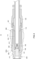
FIG. 3 a longitudinal section diagram of a rugged plug according to an embodiment of the disclosure; -
FIG. 4 a longitudinal section diagram of a rugged plug plugged in a socket according to an embodiment of the disclosure; -
FIG. 5 andFIG. 6 are schematic diagrams of a rugged plug unplugged from a socket according to an embodiment of the disclosure; -
FIG. 7 is a perspective schematic diagram of a rugged plug plugged in a socket according to another embodiment of the disclosure; and -
FIG. 8 is a flowchart of an unplugging method for a rugged plug according to an embodiment of the disclosure. - Referring to
FIG. 1 to FIG. 3 , arugged plug 10 is provided according to an embodiment of the disclosure. Therugged plug 10 includes aconnector 100, an elasticinner sheath 200 and a slidablerigid sheath 300. - In this embodiment, the
connector 100 may be in a USB type-C receptacle specification as shown inFIG. 1 , or theconnector 100 may be in a USB type-C plug specification as shown inFIG. 7 . Theconnector 100 has acoupling end 101 and awiring end 102 opposite to thecoupling end 102, and awire 110 extends from thewiring end 102 of theconnector 100. Thewiring end 102 of theconnector 100 is enveloped by areinforcement sheath 120, and thewire 110 passes through thereinforcement sheath 120. Thereinforcement sheath 120 is capable of reinforcing the structural strength of thewire 110 to prevent bending and hence breaking of thewire 110. - The slidable
rigid sheath 300 and the elasticinner sheath 220 are made of different stainless steel materials, such that the slidablerigid sheath 300 has a rigidity higher than that of the elasticinner sheath 200, and the elasticinner sheath 200 is elastic at the slidablerigid sheath 300. In this embodiment, the elasticinner sheath 200 is, for example, a cylinder made of 17-4PH stainless steel and has two open ends. The elasticinner sheath 200 sleeves theconnector 100. One end of the inner sheath is disposed corresponding to thewiring end 102 of theconnector 100 and aport 201 is provided on that end. Theport 201 packs against thewire 110, and thereinforcement sheath 120 envelops theport 201 of the elasticinner sheath 200. Anelastic arm 210 is provided on at least one side of the elasticinner sheath 200. However, the disclosure does not specifically define the number of theelastic arm 210; for example, in this embodiment, a pair ofelastic arms 210 are disposed correspondingly on two opposite sides of the elasticinner sheath 200. In this embodiment, eachelastic arms 210 extends from thewiring end 102 of theconnector 100 toward thecoupling end 101 of theconnector 101, such that an end of eachelastic arm 210 is disposed correspondingly to thecoupling end 101 of theconnector 21. However, the disclosure is not limited to the example above, and eachelastic arm 210 may also be disposed in a configuration reverse to the above. Ahook 211 is protruded from one lateral side of eachelastic arm 210. Eachhook 211 protrudes from an outer wall of the elasticinner sheath 200, and a tip of eachhook 211 is a curved surface. When eachelastic arm 210 receives a force and is biased toward into elasticinner sheath 200, thehook 211 can thus recede toward into the elasticinner sheath 200. An actuatingslope 202 is defined on eachelastic arm 210, and adirection 202n normal to each actuatingslope 202 is biased toward thecoupling end 101 of theconnector 100. In this embodiment, aboss 212 is protruded from the side of thehook 211 of the eachelastic arm 210, and the actuatingslope 202 is formed on theboss 212. A yieldingrecess 111 corresponding to eachelastic arm 210 is provided on an outer wall of thewire 110, and eachelastic arm 210 is capable of being biased and receded in each corresponding yieldingrecess 111 when biased toward into the elasticinner sheath 200 by a force received. - The slidable
rigid sheath 300 is, for example, a cylinder made of 316 stainless steel and having two open ends, and may movably sleeve the elasticinner sheath 200. At least onestop block 220 is protruded from the outer wall of the elasticinner sheath 200, and thestop block 220 and thereinforcement sheath 120 respectively correspond to two ends of a stroke of the slidablerigid sheath 300 so as to prevent the slidablerigid sheath 300 from falling off. The slidablerigid sheath 300 covers theactuating slope 202, and thehook 211 is located outside the slidablerigid sheath 211. The slidablerigid sheath 300 has anactuating structure 302, and theactuating structure 302 abuts against theactuating slope 202. In this embodiment, theactuating structure 302 may be a surface abutting against theactuating slope 202; however, the disclosure is not limited to the above example. For example, theactuating structure 302 may also be in a form of a protrusion abutting against theactuating slope 202. - Referring to
FIG.1 andFIG. 8 , an unplugging method applied to the aboverugged plug 10 is further provided according to an embodiment of the disclosure. The unplugging method includes the following steps. - Referring
FIG. 1 ,FIG. 4 andFIG. 8 , in step a, asocket 20 and therugged plug 10 are provided, wherein therugged plug 10 is configured to plug in thesocket 20. As described above, therugged plug 10 has an elasticinner sheath 200 and a slidablerigid sheath 300. The slidablerigid sheath 300 movably sleeves the elasticinner sheath 200, and the elasticinner sheath 200 is made of, for example, 17-4PH stainless steel. The slidablerigid sheath 300 and the elasticinner sheath 200 are made of different stainless steel materials. In this embodiment, the slidablerigid sheath 300 is made of, for example, 316L stainless steel. Thesocket 20 includes arigid housing 22, and the slidablerigid sheath 300 and therigid housing 22 may be made of the same stainless steel material. - The elastic
inner sheath 200 has anelastic arm 210, which is defined with ahook 211 protruded from one lateral side of theelastic arm 210. The hook protrudes 211 from the side of the elasticinner sheath 200, and a tip of thehook 211 is a curved surface. When therugged plug 10 is plugged in thesocket 20, the elasticinner sheath 200 is plugged in therigid housing 22, and thehook 211 is inserted in therigid housing 22 and is connected at therigid housing 22 of thesocket 20. - An
actuating slope 202 is defined on theelastic arm 210, and a direction normal to theactuating slope 202 is biased toward thesocket 20. The slidablerigid sheath 300 has anactuating structure 302, and theactuating structure 302 abuts against theactuating slope 202. Therugged plug 10 includes aconnector 100 inserted in the elasticinner sheath 200, and thesocket 20 includes amating connector 21 inserted in therigid housing 22. When therugged plug 10 is plugged in thesocket 20, theconnector 100 is connected to themating connector 21. If theconnector 100 is in a USB type-C receptacle specification as shown inFIG. 1 , themating connector 21 is in a USB plug specification; if theconnector 100 is in a USB type-C plug specification as shown inFIG. 7 , themating connector 21 is in a USB type-C receptacle specification. - Referring to
FIG. 4 ,FIG. 5 andFIG. 8 , in step b following step a, the slidablerigid sheath 300 is moved in a direction away from thesocket 20 such that theactuating structure 302 pushes against theactuating slope 202. Because the slidablerigid sheath 300 has a rigidity higher than that of the elasticinner sheath 200 and the elasticinner sheath 200 is elastic at the slidablerigid sheath 300, theelastic arm 210 elastically deforms when pressed by theactuating structure 302 and is biased toward into the elasticinner sheath 200. Thehook 211 recedes into the elasticinner sheath 200 and loosens thesocket 20 when theelastic arm 210 is biased toward into the elasticinner sheath 200. - In step c following step a, the slidable
rigid sheath 300 is continually moved in the direction away from thesocket 20. At this point, theactuating structure 302 still presses against theactuating slope 202, and the slidablerigid sheath 300 at the same time presses thereinforcement sheath 120, and thus therugged plug 10 in overall is pushed and moved along with the slidablerigid sheath 300. A tip of thehook 211 is a curved surface, and can thus easily slide off from thesocket 20 when therugged plug 10 moves. - Referring to
FIG. 6 andFIG.8 , in step d following step c, the slidablerigid sheath 300 is continually moved in the direction away from thesocket 20, and the rugged plugged 10 becomes receded from thesocket 20. - In conclusion, when a user unplugs the
plug 10 from thesocket 20 by operating therugged plug 10 of the disclosure using the foregoing unplugging method, the user is able to simultaneously unlock thehook 211 and recede therugged plug 10 by merely holding and pulling the slidablerigid sheath 300 in a direction away from thesocket 20. - The description above provides merely preferred embodiments of the disclosure, and are not to be construed as limitations to the scope of the claims of the disclosure. All equivalent modifications practicing the spirit of the disclosure are to be encompassed within the scope of the disclosure.
Claims (14)
- A rugged plug, comprising:a connector, having a coupling end;an elastic inner sheath, sleeving the connector, the elastic inner sheath having an elastic arm, wherein a hook is protruded from one lateral side of the elastic arm, the hook protrudes from the side of the elastic inner sheath, a tip of the hook is a curved surface, an actuating slope is defined on the elastic arm, and a direction normal to the actuating slope is biased toward the coupling end of the connector; anda slidable rigid sheath, movably sleeving the elastic inner sheath, the slidable rigid sheath covering the actuating slope, wherein the hook is located outside the slidable rigid sheath, the slidable rigid sheath has an actuating structure, and the actuating structure abuts against the actuating slope.
- The rugged plug according to claim 1, wherein the elastic inner sheath and the slidable rigid sheath are made of different stainless steel materials.
- The rugged plug according to claim 1, wherein the connector is in a USB type-C plug specification or the connector is in a USB type-C receptacle specification.
- The rugged plug according to claim 3, wherein the connector has a coupling end and a wiring end opposite to the coupling end, a wire extends from the wiring end of the connector, one end of the elastic inner sheath has a port, and the port packs against the wire.
- The rugged plug according to claim 4, wherein the wiring end of the connector is enveloped by a reinforcement sheath, and the wire passes through the reinforcement sheath and envelops the port of the elastic inner sheath.
- The rugged plug according to claim 4, wherein a yielding recess corresponding to the elastic arm is provided on an outer wall of the wire, and the elastic arm is capable of being biased and receded in the yielding recess.
- The rugged plug according to claim 1, wherein the connector has a coupling end and a wiring end opposite to the coupling end, and the elastic arm extends from the wiring end of the connector toward the coupling end of the connector.
- An unplugging method for a rugged plug, comprising:a) providing a socket and a rugged plug plugged in the socket, wherein the rugged plug has an elastic inner sheath and a slidable rigid sheath, the slidable rigid sheath movably sleeves the elastic inner sheath, the elastic inner sheath has an elastic arm, a hook is protruded laterally from the elastic arm, the hook protrudes from a side of the elastic inner sheath, a tip of the hook is a curved surface, the hook is fastened at the socket, an actuating slope is defined on the elastic arm, a direction normal to the actuating slope is biased toward the socket, an actuating structure sleeves the slidable rigid sheath, and the actuating structure abuts against the actuating slope;b) moving the slidable rigid sheath in a direction away from the socket, such that the actuating structure pushes the actuating slope and biases the elastic arm, and the hook recedes toward into the elastic inner sleeve and loosens the socket;c) continually moving the slidable rigid sleeve in the direction away from the socket to push and move the rugged plug, such that the tip of the hook slides off from the socket; andd) continually moving the slidable rigid sheath in the direction away from the socket to recede the rugged plug away from the socket.
- The unplugging method for a rugged plug according to claim 8, wherein the socket comprises a rigid housing, and the hook is connected at the rigid housing.
- The unplugging method for a rugged plug according to claim 9, wherein when the rugged plug is plugged in the socket, the elastic inner sheath is plugged in the rigid housing, and the hook is inserted in the rigid housing.
- The unplugging method for a rugged plug according to claim 9, wherein the rigid housing and the slidable rigid sheath are made of a same stainless steel material.
- The unplugging method for a rugged plug according to claim 8, wherein the elastic inner sheath and the slidable rigid sheath are made of different stainless steel materials.
- The unplugging method for a rugged plug according to claim 9, wherein the rugged plug comprises a connector inserted in the elastic inner sheath, the socket comprises a mating connector inserted in the rigid housing, and when the rugged plug is plugged in the socket, the connector is connected to the mating connector.
- The unplugging method for a rugged plug according to claim 13, wherein the connector is in a USB type-C plug specification, and the mating connector is in a USB type-C receptacle specification; or the connector is in a USB type-C receptacle specification, and the mating connector is in a USB type-C plug specification.
Applications Claiming Priority (1)
| Application Number | Priority Date | Filing Date | Title |
|---|---|---|---|
| US202263388980P | 2022-07-13 | 2022-07-13 |
Publications (2)
| Publication Number | Publication Date |
|---|---|
| EP4307492A1 true EP4307492A1 (en) | 2024-01-17 |
| EP4307492B1 EP4307492B1 (en) | 2025-10-01 |
Family
ID=85018107
Family Applications (1)
| Application Number | Title | Priority Date | Filing Date |
|---|---|---|---|
| EP23152405.9A Active EP4307492B1 (en) | 2022-07-13 | 2023-01-19 | Rugged plug and unplugging method thereof |
Country Status (5)
| Country | Link |
|---|---|
| US (2) | US12218460B2 (en) |
| EP (1) | EP4307492B1 (en) |
| CN (1) | CN117410770A (en) |
| AU (1) | AU2023200640B2 (en) |
| TW (1) | TWI835343B (en) |
Citations (2)
| Publication number | Priority date | Publication date | Assignee | Title |
|---|---|---|---|---|
| US10168488B1 (en) * | 2017-08-30 | 2019-01-01 | Te Connectivity Corporation | Tool-less ferrule retainer |
| WO2020164662A1 (en) * | 2019-02-15 | 2020-08-20 | Harting Electric Gmbh & Co. Kg | Plug connector having locking and unlocking function |
Family Cites Families (10)
| Publication number | Priority date | Publication date | Assignee | Title |
|---|---|---|---|---|
| US5171161A (en) * | 1991-05-09 | 1992-12-15 | Molex Incorporated | Electrical connector assemblies |
| US5435744A (en) * | 1994-05-19 | 1995-07-25 | The Whitaker Corporation | Sliding boot assembly for electrical connector |
| JPH0963694A (en) * | 1995-08-21 | 1997-03-07 | Honda Tsushin Kogyo Kk | Connector with locking mechanism |
| EP2351160B1 (en) * | 2008-10-15 | 2014-01-01 | Fci | Latch assembly for a connector |
| CN102346279B (en) * | 2010-07-30 | 2015-03-11 | 株式会社藤仓 | Optical connector and connector connection system |
| CN102637980B (en) * | 2012-04-01 | 2014-10-08 | 中航光电科技股份有限公司 | Push-and-pull locking electric connector and components thereof |
| JP5517272B1 (en) * | 2012-12-27 | 2014-06-11 | 日本航空電子工業株式会社 | connector |
| US9991640B2 (en) * | 2014-04-14 | 2018-06-05 | Apple Inc. | Durable connector receptacles |
| JP6635588B2 (en) * | 2015-12-17 | 2020-01-29 | 日本航空電子工業株式会社 | connector |
| US11658439B2 (en) * | 2020-02-19 | 2023-05-23 | Getac Technology Corporation | Male plug and female receptacle of connector and docking structure thereof |
-
2022
- 2022-10-12 TW TW111138655A patent/TWI835343B/en active
- 2022-10-12 CN CN202211247884.1A patent/CN117410770A/en active Pending
-
2023
- 2023-01-17 US US18/098,051 patent/US12218460B2/en active Active
- 2023-01-19 EP EP23152405.9A patent/EP4307492B1/en active Active
- 2023-02-07 AU AU2023200640A patent/AU2023200640B2/en active Active
-
2024
- 2024-12-26 US US19/001,669 patent/US20250125562A1/en active Pending
Patent Citations (2)
| Publication number | Priority date | Publication date | Assignee | Title |
|---|---|---|---|---|
| US10168488B1 (en) * | 2017-08-30 | 2019-01-01 | Te Connectivity Corporation | Tool-less ferrule retainer |
| WO2020164662A1 (en) * | 2019-02-15 | 2020-08-20 | Harting Electric Gmbh & Co. Kg | Plug connector having locking and unlocking function |
Also Published As
| Publication number | Publication date |
|---|---|
| US20250125562A1 (en) | 2025-04-17 |
| US12218460B2 (en) | 2025-02-04 |
| TW202404202A (en) | 2024-01-16 |
| EP4307492B1 (en) | 2025-10-01 |
| US20240022022A1 (en) | 2024-01-18 |
| AU2023200640A1 (en) | 2024-02-01 |
| AU2023200640B2 (en) | 2024-08-15 |
| TWI835343B (en) | 2024-03-11 |
| CN117410770A (en) | 2024-01-16 |
Similar Documents
| Publication | Publication Date | Title |
|---|---|---|
| US7303220B2 (en) | Connector coupling/decoupling tool | |
| US7473124B1 (en) | Electrical plug assembly with bi-directional push-pull actuator | |
| CN102237610B (en) | Low profile socket connector with flexing lock arm | |
| EP2859625B1 (en) | Connector assembly and connector product | |
| US9151907B2 (en) | Optical fiber connector | |
| US20110131801A1 (en) | Connector removal tool | |
| CN101022191B (en) | Lever fitting-type connector | |
| KR20080077908A (en) | Lock structure of electrical connection mechanism | |
| US9941631B1 (en) | Plug and cable with plug | |
| US20100289255A1 (en) | Insertable tube system for a vacuum cleaner | |
| JP2015516666A (en) | Locking electrical connector | |
| CN111650696A (en) | Tools for plugs, sliders, plugs and cables with plugs | |
| CN115377728A (en) | Plug connector and connector set with lever extension | |
| EP1619761A1 (en) | Connector for mobile communication device | |
| US20240022022A1 (en) | Rugged plug and unplugging method thereof | |
| CN106887726B (en) | Clamping devices, electrical connectors and connector assemblies | |
| EP1071167B1 (en) | Plug-in connector with cable strain relief | |
| CN113917617A (en) | Optical dust protector and optical connector module thereof | |
| CN108292820B (en) | Connector type female plug | |
| US20120100732A1 (en) | Assisting apparatus for plugging or unplugging connector | |
| CN110391548B (en) | Plug unlocking assembly and plug and plug housing assembly | |
| KR20200100478A (en) | Connector | |
| KR101820142B1 (en) | Device for preventing seperation connector | |
| US20190190222A1 (en) | Insertion Tool for Right-Angled RF Connectors | |
| JP5288509B2 (en) | Push-on / push-off connector and jack connector |
Legal Events
| Date | Code | Title | Description |
|---|---|---|---|
| PUAI | Public reference made under article 153(3) epc to a published international application that has entered the european phase |
Free format text: ORIGINAL CODE: 0009012 |
|
| STAA | Information on the status of an ep patent application or granted ep patent |
Free format text: STATUS: THE APPLICATION HAS BEEN PUBLISHED |
|
| AK | Designated contracting states |
Kind code of ref document: A1 Designated state(s): AL AT BE BG CH CY CZ DE DK EE ES FI FR GB GR HR HU IE IS IT LI LT LU LV MC ME MK MT NL NO PL PT RO RS SE SI SK SM TR |
|
| STAA | Information on the status of an ep patent application or granted ep patent |
Free format text: STATUS: REQUEST FOR EXAMINATION WAS MADE |
|
| 17P | Request for examination filed |
Effective date: 20240507 |
|
| RBV | Designated contracting states (corrected) |
Designated state(s): AL AT BE BG CH CY CZ DE DK EE ES FI FR GB GR HR HU IE IS IT LI LT LU LV MC ME MK MT NL NO PL PT RO RS SE SI SK SM TR |
|
| STAA | Information on the status of an ep patent application or granted ep patent |
Free format text: STATUS: EXAMINATION IS IN PROGRESS |
|
| 17Q | First examination report despatched |
Effective date: 20241030 |
|
| GRAP | Despatch of communication of intention to grant a patent |
Free format text: ORIGINAL CODE: EPIDOSNIGR1 |
|
| STAA | Information on the status of an ep patent application or granted ep patent |
Free format text: STATUS: GRANT OF PATENT IS INTENDED |
|
| RIC1 | Information provided on ipc code assigned before grant |
Ipc: H01R 13/635 20060101AFI20250610BHEP Ipc: H01R 13/627 20060101ALI20250610BHEP Ipc: H01R 43/26 20060101ALI20250610BHEP Ipc: H01R 13/516 20060101ALN20250610BHEP |
|
| RIC1 | Information provided on ipc code assigned before grant |
Ipc: H01R 13/635 20060101AFI20250617BHEP Ipc: H01R 13/627 20060101ALI20250617BHEP Ipc: H01R 43/26 20060101ALI20250617BHEP Ipc: H01R 13/516 20060101ALN20250617BHEP |
|
| INTG | Intention to grant announced |
Effective date: 20250626 |
|
| GRAS | Grant fee paid |
Free format text: ORIGINAL CODE: EPIDOSNIGR3 |
|
| GRAA | (expected) grant |
Free format text: ORIGINAL CODE: 0009210 |
|
| STAA | Information on the status of an ep patent application or granted ep patent |
Free format text: STATUS: THE PATENT HAS BEEN GRANTED |
|
| AK | Designated contracting states |
Kind code of ref document: B1 Designated state(s): AL AT BE BG CH CY CZ DE DK EE ES FI FR GB GR HR HU IE IS IT LI LT LU LV MC ME MK MT NL NO PL PT RO RS SE SI SK SM TR |
|
| REG | Reference to a national code |
Ref country code: GB Ref legal event code: FG4D Ref country code: CH Ref legal event code: F10 Free format text: ST27 STATUS EVENT CODE: U-0-0-F10-F00 (AS PROVIDED BY THE NATIONAL OFFICE) Effective date: 20251001 |
|
| REG | Reference to a national code |
Ref country code: IE Ref legal event code: FG4D |
|
| REG | Reference to a national code |
Ref country code: DE Ref legal event code: R096 Ref document number: 602023006996 Country of ref document: DE |
|
| REG | Reference to a national code |
Ref country code: NL Ref legal event code: MP Effective date: 20251001 |
|
| REG | Reference to a national code |
Ref country code: AT Ref legal event code: MK05 Ref document number: 1843551 Country of ref document: AT Kind code of ref document: T Effective date: 20251001 |
|
| PG25 | Lapsed in a contracting state [announced via postgrant information from national office to epo] |
Ref country code: NL Free format text: LAPSE BECAUSE OF FAILURE TO SUBMIT A TRANSLATION OF THE DESCRIPTION OR TO PAY THE FEE WITHIN THE PRESCRIBED TIME-LIMIT Effective date: 20251001 |
|
| PG25 | Lapsed in a contracting state [announced via postgrant information from national office to epo] |
Ref country code: ES Free format text: LAPSE BECAUSE OF FAILURE TO SUBMIT A TRANSLATION OF THE DESCRIPTION OR TO PAY THE FEE WITHIN THE PRESCRIBED TIME-LIMIT Effective date: 20251001 |
|
| REG | Reference to a national code |
Ref country code: LT Ref legal event code: MG9D |
|
| PG25 | Lapsed in a contracting state [announced via postgrant information from national office to epo] |
Ref country code: NO Free format text: LAPSE BECAUSE OF FAILURE TO SUBMIT A TRANSLATION OF THE DESCRIPTION OR TO PAY THE FEE WITHIN THE PRESCRIBED TIME-LIMIT Effective date: 20260101 |
|
| PGFP | Annual fee paid to national office [announced via postgrant information from national office to epo] |
Ref country code: DE Payment date: 20260108 Year of fee payment: 4 |
|
| PG25 | Lapsed in a contracting state [announced via postgrant information from national office to epo] |
Ref country code: AT Free format text: LAPSE BECAUSE OF FAILURE TO SUBMIT A TRANSLATION OF THE DESCRIPTION OR TO PAY THE FEE WITHIN THE PRESCRIBED TIME-LIMIT Effective date: 20251001 Ref country code: FI Free format text: LAPSE BECAUSE OF FAILURE TO SUBMIT A TRANSLATION OF THE DESCRIPTION OR TO PAY THE FEE WITHIN THE PRESCRIBED TIME-LIMIT Effective date: 20251001 Ref country code: HR Free format text: LAPSE BECAUSE OF FAILURE TO SUBMIT A TRANSLATION OF THE DESCRIPTION OR TO PAY THE FEE WITHIN THE PRESCRIBED TIME-LIMIT Effective date: 20251001 |
|
| PGFP | Annual fee paid to national office [announced via postgrant information from national office to epo] |
Ref country code: IT Payment date: 20260131 Year of fee payment: 4 |
|
| PG25 | Lapsed in a contracting state [announced via postgrant information from national office to epo] |
Ref country code: RS Free format text: LAPSE BECAUSE OF FAILURE TO SUBMIT A TRANSLATION OF THE DESCRIPTION OR TO PAY THE FEE WITHIN THE PRESCRIBED TIME-LIMIT Effective date: 20260101 |
|
| PG25 | Lapsed in a contracting state [announced via postgrant information from national office to epo] |
Ref country code: IS Free format text: LAPSE BECAUSE OF FAILURE TO SUBMIT A TRANSLATION OF THE DESCRIPTION OR TO PAY THE FEE WITHIN THE PRESCRIBED TIME-LIMIT Effective date: 20260201 |
|
| PGFP | Annual fee paid to national office [announced via postgrant information from national office to epo] |
Ref country code: FR Payment date: 20260108 Year of fee payment: 4 |
|
| PG25 | Lapsed in a contracting state [announced via postgrant information from national office to epo] |
Ref country code: CZ Free format text: LAPSE BECAUSE OF FAILURE TO SUBMIT A TRANSLATION OF THE DESCRIPTION OR TO PAY THE FEE WITHIN THE PRESCRIBED TIME-LIMIT Effective date: 20251001 Ref country code: PT Free format text: LAPSE BECAUSE OF FAILURE TO SUBMIT A TRANSLATION OF THE DESCRIPTION OR TO PAY THE FEE WITHIN THE PRESCRIBED TIME-LIMIT Effective date: 20260202 |
|
| PG25 | Lapsed in a contracting state [announced via postgrant information from national office to epo] |
Ref country code: PL Free format text: LAPSE BECAUSE OF FAILURE TO SUBMIT A TRANSLATION OF THE DESCRIPTION OR TO PAY THE FEE WITHIN THE PRESCRIBED TIME-LIMIT Effective date: 20251001 |
|
| PG25 | Lapsed in a contracting state [announced via postgrant information from national office to epo] |
Ref country code: LV Free format text: LAPSE BECAUSE OF FAILURE TO SUBMIT A TRANSLATION OF THE DESCRIPTION OR TO PAY THE FEE WITHIN THE PRESCRIBED TIME-LIMIT Effective date: 20251001 |
|
| PG25 | Lapsed in a contracting state [announced via postgrant information from national office to epo] |
Ref country code: BG Free format text: LAPSE BECAUSE OF FAILURE TO SUBMIT A TRANSLATION OF THE DESCRIPTION OR TO PAY THE FEE WITHIN THE PRESCRIBED TIME-LIMIT Effective date: 20251001 |