EP4307441A1 - Battery and electrical device - Google Patents
Battery and electrical device Download PDFInfo
- Publication number
- EP4307441A1 EP4307441A1 EP22936038.3A EP22936038A EP4307441A1 EP 4307441 A1 EP4307441 A1 EP 4307441A1 EP 22936038 A EP22936038 A EP 22936038A EP 4307441 A1 EP4307441 A1 EP 4307441A1
- Authority
- EP
- European Patent Office
- Prior art keywords
- battery
- battery cell
- thermal management
- management component
- present application
- Prior art date
- Legal status (The legal status is an assumption and is not a legal conclusion. Google has not performed a legal analysis and makes no representation as to the accuracy of the status listed.)
- Pending
Links
Images


Classifications
-
- H—ELECTRICITY
- H01—ELECTRIC ELEMENTS
- H01M—PROCESSES OR MEANS, e.g. BATTERIES, FOR THE DIRECT CONVERSION OF CHEMICAL ENERGY INTO ELECTRICAL ENERGY
- H01M10/00—Secondary cells; Manufacture thereof
- H01M10/60—Heating or cooling; Temperature control
- H01M10/65—Means for temperature control structurally associated with the cells
- H01M10/655—Solid structures for heat exchange or heat conduction
- H01M10/6554—Rods or plates
-
- C—CHEMISTRY; METALLURGY
- C09—DYES; PAINTS; POLISHES; NATURAL RESINS; ADHESIVES; COMPOSITIONS NOT OTHERWISE PROVIDED FOR; APPLICATIONS OF MATERIALS NOT OTHERWISE PROVIDED FOR
- C09J—ADHESIVES; NON-MECHANICAL ASPECTS OF ADHESIVE PROCESSES IN GENERAL; ADHESIVE PROCESSES NOT PROVIDED FOR ELSEWHERE; USE OF MATERIALS AS ADHESIVES
- C09J7/00—Adhesives in the form of films or foils
-
- C—CHEMISTRY; METALLURGY
- C09—DYES; PAINTS; POLISHES; NATURAL RESINS; ADHESIVES; COMPOSITIONS NOT OTHERWISE PROVIDED FOR; APPLICATIONS OF MATERIALS NOT OTHERWISE PROVIDED FOR
- C09J—ADHESIVES; NON-MECHANICAL ASPECTS OF ADHESIVE PROCESSES IN GENERAL; ADHESIVE PROCESSES NOT PROVIDED FOR ELSEWHERE; USE OF MATERIALS AS ADHESIVES
- C09J9/00—Adhesives characterised by their physical nature or the effects produced, e.g. glue sticks
- C09J9/02—Electrically-conducting adhesives
-
- H—ELECTRICITY
- H01—ELECTRIC ELEMENTS
- H01M—PROCESSES OR MEANS, e.g. BATTERIES, FOR THE DIRECT CONVERSION OF CHEMICAL ENERGY INTO ELECTRICAL ENERGY
- H01M10/00—Secondary cells; Manufacture thereof
- H01M10/60—Heating or cooling; Temperature control
- H01M10/64—Heating or cooling; Temperature control characterised by the shape of the cells
- H01M10/647—Prismatic or flat cells, e.g. pouch cells
-
- H—ELECTRICITY
- H01—ELECTRIC ELEMENTS
- H01M—PROCESSES OR MEANS, e.g. BATTERIES, FOR THE DIRECT CONVERSION OF CHEMICAL ENERGY INTO ELECTRICAL ENERGY
- H01M10/00—Secondary cells; Manufacture thereof
- H01M10/60—Heating or cooling; Temperature control
- H01M10/65—Means for temperature control structurally associated with the cells
- H01M10/656—Means for temperature control structurally associated with the cells characterised by the type of heat-exchange fluid
- H01M10/6567—Liquids
-
- H—ELECTRICITY
- H01—ELECTRIC ELEMENTS
- H01M—PROCESSES OR MEANS, e.g. BATTERIES, FOR THE DIRECT CONVERSION OF CHEMICAL ENERGY INTO ELECTRICAL ENERGY
- H01M50/00—Constructional details or processes of manufacture of the non-active parts of electrochemical cells other than fuel cells, e.g. hybrid cells
- H01M50/10—Primary casings; Jackets or wrappings
- H01M50/102—Primary casings; Jackets or wrappings characterised by their shape or physical structure
- H01M50/103—Primary casings; Jackets or wrappings characterised by their shape or physical structure prismatic or rectangular
-
- C—CHEMISTRY; METALLURGY
- C09—DYES; PAINTS; POLISHES; NATURAL RESINS; ADHESIVES; COMPOSITIONS NOT OTHERWISE PROVIDED FOR; APPLICATIONS OF MATERIALS NOT OTHERWISE PROVIDED FOR
- C09J—ADHESIVES; NON-MECHANICAL ASPECTS OF ADHESIVE PROCESSES IN GENERAL; ADHESIVE PROCESSES NOT PROVIDED FOR ELSEWHERE; USE OF MATERIALS AS ADHESIVES
- C09J2203/00—Applications of adhesives in processes or use of adhesives in the form of films or foils
- C09J2203/33—Applications of adhesives in processes or use of adhesives in the form of films or foils for batteries or fuel cells
-
- C—CHEMISTRY; METALLURGY
- C09—DYES; PAINTS; POLISHES; NATURAL RESINS; ADHESIVES; COMPOSITIONS NOT OTHERWISE PROVIDED FOR; APPLICATIONS OF MATERIALS NOT OTHERWISE PROVIDED FOR
- C09J—ADHESIVES; NON-MECHANICAL ASPECTS OF ADHESIVE PROCESSES IN GENERAL; ADHESIVE PROCESSES NOT PROVIDED FOR ELSEWHERE; USE OF MATERIALS AS ADHESIVES
- C09J2301/00—Additional features of adhesives in the form of films or foils
- C09J2301/20—Additional features of adhesives in the form of films or foils characterized by the structural features of the adhesive itself
- C09J2301/208—Additional features of adhesives in the form of films or foils characterized by the structural features of the adhesive itself the adhesive layer being constituted by at least two or more adjacent or superposed adhesive layers, e.g. multilayer adhesive
-
- C—CHEMISTRY; METALLURGY
- C09—DYES; PAINTS; POLISHES; NATURAL RESINS; ADHESIVES; COMPOSITIONS NOT OTHERWISE PROVIDED FOR; APPLICATIONS OF MATERIALS NOT OTHERWISE PROVIDED FOR
- C09J—ADHESIVES; NON-MECHANICAL ASPECTS OF ADHESIVE PROCESSES IN GENERAL; ADHESIVE PROCESSES NOT PROVIDED FOR ELSEWHERE; USE OF MATERIALS AS ADHESIVES
- C09J2301/00—Additional features of adhesives in the form of films or foils
- C09J2301/20—Additional features of adhesives in the form of films or foils characterized by the structural features of the adhesive itself
- C09J2301/21—Additional features of adhesives in the form of films or foils characterized by the structural features of the adhesive itself the adhesive layer being formed by alternating adhesive areas of different nature
-
- C—CHEMISTRY; METALLURGY
- C09—DYES; PAINTS; POLISHES; NATURAL RESINS; ADHESIVES; COMPOSITIONS NOT OTHERWISE PROVIDED FOR; APPLICATIONS OF MATERIALS NOT OTHERWISE PROVIDED FOR
- C09J—ADHESIVES; NON-MECHANICAL ASPECTS OF ADHESIVE PROCESSES IN GENERAL; ADHESIVE PROCESSES NOT PROVIDED FOR ELSEWHERE; USE OF MATERIALS AS ADHESIVES
- C09J2301/00—Additional features of adhesives in the form of films or foils
- C09J2301/30—Additional features of adhesives in the form of films or foils characterized by the chemical, physicochemical or physical properties of the adhesive or the carrier
- C09J2301/314—Additional features of adhesives in the form of films or foils characterized by the chemical, physicochemical or physical properties of the adhesive or the carrier the adhesive layer and/or the carrier being conductive
-
- H—ELECTRICITY
- H01—ELECTRIC ELEMENTS
- H01M—PROCESSES OR MEANS, e.g. BATTERIES, FOR THE DIRECT CONVERSION OF CHEMICAL ENERGY INTO ELECTRICAL ENERGY
- H01M2220/00—Batteries for particular applications
- H01M2220/20—Batteries in motive systems, e.g. vehicle, ship, plane
-
- H—ELECTRICITY
- H01—ELECTRIC ELEMENTS
- H01M—PROCESSES OR MEANS, e.g. BATTERIES, FOR THE DIRECT CONVERSION OF CHEMICAL ENERGY INTO ELECTRICAL ENERGY
- H01M50/00—Constructional details or processes of manufacture of the non-active parts of electrochemical cells other than fuel cells, e.g. hybrid cells
- H01M50/20—Mountings; Secondary casings or frames; Racks, modules or packs; Suspension devices; Shock absorbers; Transport or carrying devices; Holders
- H01M50/204—Racks, modules or packs for multiple batteries or multiple cells
- H01M50/207—Racks, modules or packs for multiple batteries or multiple cells characterised by their shape
- H01M50/209—Racks, modules or packs for multiple batteries or multiple cells characterised by their shape adapted for prismatic or rectangular cells
-
- Y—GENERAL TAGGING OF NEW TECHNOLOGICAL DEVELOPMENTS; GENERAL TAGGING OF CROSS-SECTIONAL TECHNOLOGIES SPANNING OVER SEVERAL SECTIONS OF THE IPC; TECHNICAL SUBJECTS COVERED BY FORMER USPC CROSS-REFERENCE ART COLLECTIONS [XRACs] AND DIGESTS
- Y02—TECHNOLOGIES OR APPLICATIONS FOR MITIGATION OR ADAPTATION AGAINST CLIMATE CHANGE
- Y02E—REDUCTION OF GREENHOUSE GAS [GHG] EMISSIONS, RELATED TO ENERGY GENERATION, TRANSMISSION OR DISTRIBUTION
- Y02E60/00—Enabling technologies; Technologies with a potential or indirect contribution to GHG emissions mitigation
- Y02E60/10—Energy storage using batteries
Definitions
- the present application relates to the field of battery technology, and in particular, to a battery and an electric device.
- the present application provides a battery and an electric device, which can improve the safety of the batteries.
- the present application provides a battery, including: a battery cell; a thermal management component configured for accommodating fluid to adjust the temperature of the battery cell; a connector, provided between the thermal management component and the first surface of the battery cell and configured for making the thermal management component attached to the first surface, wherein the first surface is a concave-convex surface.
- the first surface of the battery cell is provided as the concave-convex surface, which can increase the contact area between the first surface and the connector, avoid occurrence of the situation that the thermal management component is separated from the battery cell which is caused by the mutual separation phenomenon occurring due to expansion or mechanical vibration of the battery cell (the phenomenon that the connector is separated from the first surface due to expansion force or vibration), and ensure that the thermal management component is stably connected to the battery cell, so that the thermal management component can effectively adjust the temperature of the battery cell to ensure the safety of the battery.
- the connector is an adhesive layer.
- the thermal management component is bonded to the first surface of the battery cell through the adhesive layer.
- the assembly efficiency of the thermal management component and the battery cell can be improved, and on the other hand, since the first surface is the concave-convex surface, there is a larger bonding area between the adhesive layer and the battery cell, which can avoid occurrence of the situation that the thermal management component is separated from the battery cell which is caused by the debonding phenomenon occurring due to the expansion or mechanical vibration of the battery cell (the adhesive layer is separated from the first surface) and ensure that the thermal management component is stably connected to the battery cell, so that the thermal management component can effectively adjust the temperature of the battery cell to ensure the safety of the battery.
- the first surface has multiple grooves
- the adhesive layer has a second surface and a third surface opposite to each other in its thickness direction
- the second surface is connected to the thermal management component
- the third surface has multiple protrusions
- the protrusions are embedded in the grooves.
- the protrusions on the third surface of the adhesive layer are embedded in the grooves on the first surface of the battery cell, which can effectively improve the connection strength between the adhesive layer and the battery cell, thereby ensuring the connection strength between the battery cell and the thermal management component, and avoid debonding phenomenon occurring due to the expansion force of the battery cell itself or the mechanical vibration of the battery cell, to ensure that the thermal management component is stably connected to the battery cell to effectively adjust the temperature of the battery cell and further ensure the safety of the battery.
- the multiple grooves are in dense dot-like arrangement.
- the number of the grooves is multiple, and the multiple grooves are in dot-like arrangement. On the one hand, it can effectively increase the bonding area between the first surface and the adhesive layer, and on the other hand, it can enable uniform force between the first surface and the adhesive layer.
- Each protrusion is embedded in the corresponding groove, which can effectively improve the connection strength between the adhesive layer and the first surface, so that the thermal management component is stably connected with the battery cell, ensuring the safety of the battery.
- the groove is tapered.
- tapered grooves can be conveniently and quickly formed on the first surface of the battery cell by means of stamping, etc., so as to reduce the difficulty in manufacturing of the battery cell.
- the adhesive solution is injected between the thermal management component and the first surface, which can facilitate filling the adhesive solution into the grooves (the inner diameter of each of the grooves gradually decreases along its depth, so the adhesive solution is first filled in the portion with a large inner diameter, and as the amount of injected adhesive solution increases, it is gradually filled in the deep part with a small inner diameter, wherein since the inner diameter of the deep part is small, the filling amount is small, and the load of solution injection may be reduced), to form the protrusions after the adhesive solution is solidified.
- the stable connection between the thermal management component and the battery cell is achieved by tightly bonding the protrusions to the inner walls of the grooves.
- the grooves extend in a first direction
- the multiple grooves are arranged at intervals in a second direction
- the first direction is perpendicular to the second direction.
- the multiple grooves are arranged at intervals in the second direction, and each groove extends in the first direction, which can effectively increase the bonding area between the first surface and the adhesive layer, thereby ensuring the connection strength between the battery cell and the thermal management component, avoiding that the thermal management component is separated from the battery cell and ensuring the safety of the battery.
- the first surface is a rectangular surface, one of the first direction and the second direction is the length direction of the first surface, and the other is the width direction of the first surface.
- the first surface is a rectangular surface
- one of the first direction and the second direction is the length direction of the first surface
- the other is the width direction of the first surface
- two ends of each groove respectively extend to edges of the first surface.
- the two ends of each groove extend to the edges of the first surface.
- the groove extends from one edge of the first surface to another edge, which can reduce the difficulty in forming the groove, and on the other hand, it is convenient to inject the adhesive solution (adhesive injection) into the groove from the edge of the first surface, improve the efficiency of adhesive injection, and ensure that the groove is full of the adhesive solution, so that the adhesive layer formed after the solidification of the adhesive solution can be closely bonded to the inner wall of the groove and the non-groove area of the first surface, to ensure the connection strength between the adhesive layer and the battery cell.
- the cross-section of the groove is triangular or rectangular.
- the protrusion when the cross-section of the groove is triangular, the protrusion is correspondingly triangular, and the two mutually inclined outer walls of the protrusion are bonded to the two mutually inclined inner walls of the groove, that is, two surfaces of the protrusion are bonded to the two surfaces of the groove, which can increase the bonding area between the first surface and the adhesive layer.
- the protrusion When the cross-section of the groove is rectangular, the protrusion is correspondingly rectangular, and the top wall and two opposite side walls of the protrusion are bonded to the top wall and the opposite side walls of the groove respectively, that is, the three surfaces of the protrusion are bonded to the three surfaces of the groove, which can effectively increase the bonding area between the first surface and the adhesive layer.
- the battery cell includes a casing and an end cover, wherein the casing includes a bottom wall and a side wall, the side wall surrounds the bottom wall, with one end of the side wall being connected to the bottom wall, and the other end of the side wall defining an opening, the end cover covers the opening, and the first surface is the outer surface of the bottom wall.
- the thermal management component is provided at the bottom wall of the battery cell.
- the connection strength between the bottom wall and the connector can be improved, further improving the connection strength between the bottom wall and the thermal management component, avoiding the thermal management component from being separated from the battery cell, and ensuring the safety of the battery.
- the present application further provides an electric device, including the battery according to any one of the first aspect, wherein the battery is used to provide electric energy.
- a and/or B may indicate that: there is A, there are both A and B, and there is B.
- the character "/" in the present application generally indicates that the associated objects therebefore and thereafter have “or” relationship.
- the same reference signs denote the same components, and for the sake of brevity, detailed descriptions of the same components are omitted in different embodiments. It should be understood that the thickness, length, width and other dimensions of the various components in the embodiments of the present application, as well as the overall thickness, length, width and other dimensions of the integrated device, shown in the drawings, are for illustrative description only, and should not constitute any limitation to the present application.
- the battery mentioned in the embodiments of the present application refers to a single physical module including one or more battery cells to provide higher voltage and capacity.
- the battery generally includes a box body used for packaging one or more battery cells.
- the box body can prevent liquid or other foreign objects from affecting the charging or discharging of the battery cell(s).
- Multiple in the present application refers to two or more (including two).
- the battery cell may include lithium-ion battery, lithium-sulfur battery, sodium-lithium-ion battery, sodium-ion battery, or magnesium-ion battery, etc., which are not limited in the embodiments of the present application.
- the core component of the battery that can realize the repeated charging and discharging functions is the electrode assembly in the battery cell.
- the electrode assembly includes electrode plates and a separator.
- the electrode plates include a positive electrode plate and a negative electrode plate.
- the separator is usually arranged between the positive electrode plate and the negative electrode plate to insulate the positive electrode plate and the negative electrode plate from each other.
- the material of the separator may be PP (polypropylene) or PE (polyethylene), etc.
- the battery cell works mainly by moving metal ions between the positive electrode plate and negative electrode plate.
- the electrode plate includes a current collector and an active material layer.
- the current collector has a coating area coated with the active material layer and an uncoated area not coated with the active material layer, in the width direction of the electrode plate.
- the current collector not coated with the active material layer is cut to obtain tab(s), and the tab(s) realizes the charging and discharging of the electrode assembly.
- the current collector may be metal foil, such as copper foil,
- a battery provides energy for the running of the vehicle body and the operation of various electric components in the vehicle body.
- a battery includes battery cell(s) and a thermal management component, the thermal management component is attached to the bottom wall of the battery cell(s) through a connector, and the thermal management component is used to accommodate a fluid (cooling liquid) to cool the battery cell(s), so that the battery cell(s) is subjected to charging and discharging at a safe temperature to ensure the safety of the battery.
- the surface of the bottom wall of each battery cell is a flat surface, and the connection strength between the thermal management component and the bottom wall of each battery cell is not high.
- connection strength between the thermal management component and the bottom wall of each battery cell is not high, when the battery cell expands due to charging and discharging, wherein the expansion force makes the bottom wall of the battery cell deformed, causing separation of the connector between the bottom wall of the battery cell and the thermal management component, or the connector is separated from the battery cell due to the mechanical vibration of the battery (the battery vibrates under external force, for example, the vibration of the battery generated during transportation, or the vibration generated due to vehicle travelling when the battery is applied to the vehicle), thus causing the thermal management component and the battery cell to separate from each other, thereby affecting the ability that the thermal management component adjusts the temperature of the battery cell, and affecting the safety of the battery.
- the inventors designed a battery through in-depth research, with the battery including the battery cell(s), the thermal management component and the connector.
- the thermal management component is used to accommodate a fluid to adjust the temperature of the battery cell(s).
- the connector is provided between the first surface(s) of the battery cell(s) and the thermal management component, and is used to make the thermal management component attached to the first surface(s).
- the first surface is a concave-convex surface.
- the first surface of the battery cell is a concave-convex surface.
- the contact area between the first surface and the connector can be increased, and the connection strength between the first surface and the connector is improved, so as to avoid occurrence of the situation that the thermal management component is separated from the battery cell which is caused by the mutual separation phenomenon occurring due to expansion or mechanical vibration of the battery cell (the phenomenon that the connector is separated from the first surface due to expansion force or vibration), and ensure that the thermal management component is stably connected to the battery cell, so that the thermal management component can effectively adjust the temperature of the battery cell, thereby ensuring the safety of the battery.
- the electric device may be a vehicle, a mobile phone, a portable device, a laptop, a ship, a spacecraft, an electric toy and an electric tool, etc.
- the vehicle may be new energy vehicle, and the new energy vehicle may be pure electric vehicle, hybrid power vehicle or extended-range vehicle, etc.
- the spacecraft includes airplane, rocket, space shuttle and spacecraft, etc.
- the electric toy includes fixed or mobile electric toy, for example, game console, electric car toy, electric ship toy and electric airplane toy, etc.
- the electric tool includes metal cutting electric tool, grinding electric tool, assembly electric tool and railway electric tool, for example, electric drill, electric grinder, electric wrench, electric screwdriver, electric hammer, impact electric drill, concrete vibrator and electric planer, etc.
- the embodiment of the present application does not specifically define the above electric devices.
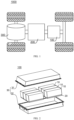
- FIG. 1 is a schematic structural view of a vehicle in some embodiments of the present application.
- a controller 200, a motor 300 and a battery 100 may be provided inside the vehicle 1000, and the controller 200 is used to control the battery 100 to supply power to the motor 300.
- the battery 100 may be provided at the bottom or head or tail of the vehicle 1000.
- the battery 100 may be used to supply power to the vehicle.
- the battery 100 may be used as an operating power source of the vehicle 1000, for a circuit system of the vehicle 1000, for example, for working power requirements during starting, navigating, and running of the vehicle 1000.
- the battery 100 can not only be used as an operating power source for the vehicle 1000, but also be used as a driving power source for the vehicle 1000, to replace or partially replace fuel oil or natural gas to provide driving power for the vehicle 1000.
- FIG. 2 is an exploded view of a battery in some embodiments of the present application.
- the battery 100 includes battery cells 10, a box body 30, and a thermal management component 20.
- the battery cells 10 are accommodated in the box body 30.
- the thermal management component 20 is arranged on the bottom walls 120 of the battery cells 10.
- the thermal management component 20 is used to accommodate a fluid, wherein the fluid may be a medium for regulating the temperature of the battery cells 10, such as cooling gas flow, cooling liquid, and the like.
- the box body 30 is used to provide accommodation space for the battery cells 10, and the box body 30 may be in various structures.
- the box body 30 may include a first part 31 and a second part 32, wherein the first part 31 and the second part 32 cover each other, and the first part 31 and the second part 32 together define an accommodation space used for accommodating the battery cells 10.
- the second part 32 may be in a hollow structure with one end open, the first part 31 may be in a plate-shaped structure, and the first part 31 covers the opening side of the second part 32, so that the first part 31 and the second part 32 together define the accommodation space.
- the first part 31 and the second part 32 may also each be in a hollow structure with one side open, and the opening side of the first part 31 covers the opening side of the second part 32.
- the box body 30 formed by the first part 31 and the second part 32 may be in various shapes, such as cylinder, cuboid and so on.
- each battery cell 10 may be fixed to the box body 30 by corresponding fasteners (such as bolts), or each battery cell 10 may be fixed to the box body 30 by means of bonding.
- FIG. 3 is a three-dimensional exploded view of the battery cell 10, the connector 40 and the thermal management component 20 in some embodiments of the present application
- FIG. 4 is schematic view of the battery cell 10, the connector 40 and the thermal management component 20 in some embodiments of the present application.
- the battery includes a battery cell 10, a thermal management component 20 and a connector 40.
- the thermal management component 20 is used to accommodate a fluid to adjust the temperature of the battery cell 10.
- the connector 40 is provided between the first surface 11 of the battery cell 10 and the thermal management component 20, for making the thermal management component 20 attached to the first surface 11.
- the first surface 11 is a concave-convex surface.
- the first surface 11 is an end surface, of the battery cell 10, connected to the connector 40, and is also a surface of the battery cell 10 that exchanges heat with the thermal management component 20.
- the first surface 11 is a concave-convex surface, which means that the first surface 11 is not a flat surface, but is uneven. Compared with the solution in which it is a flat surface, it has a larger contact area with the connector 40.
- the thermal management component 20 is a component used for performing thermal management on the battery, which can exchange heat with the battery through a medium to control the temperature.
- the thermal management component 20 may be a component for accommodating a fluid, and the thermal management component 20 may exchange heat with the battery cell 10 through the fluid to adjust the temperature of the battery cell 10, so as to ensure the safety of the battery cell 10.
- the thermal management component 20 may be a water-cooled plate, and the fluid accommodated therein is cooling liquid, wherein the heat of the battery cell 10 generated due to charging and discharging is taken away by the cooling liquid.
- the thermal management component 20 may also be used to raise the temperature of multiple battery cells 10 by heating the fluid, which is not limited in this embodiment of the present application.
- the connector 40 is a component that makes the thermal management component 20 attached to the first surface 11 of the battery cell 10.
- the first surface 11 of the battery cell 10 is a concave-convex surface.
- the contact area between the first surface 11 and the connector 40 can be increased, that is, the connection strength between the first surface 11 and the connector 40 is increased, so as to avoid occurrence of the situation that the thermal management component 20 is separated from the battery cell which is caused by the mutual separation phenomenon occurring due to expansion or mechanical vibration of the battery cell 10 (the phenomenon that the connector 40 is separated from the first surface due to expansion force or vibration), and ensure that the thermal management component 20 is stably connected to the battery cell 10, so that the thermal management component 20 can effectively adjust the temperature of the battery cell 10, thus ensuring the safety of the battery; and on the other hand, the heat exchange area between the thermal management component 20 and the battery cell 10 can be increased, thereby improving the heat conduction efficiency between the thermal management component 20 and the battery cell 10.
- the connector 40 is an adhesive layer.
- the adhesive layer a component that connects the battery cell 10 to the thermal management component 20, may be formed by solidifying an adhesive solution with adhesive property.
- the adhesive layer is formed by injecting an adhesive solution between the first surface 11 of the battery cell 10 and the thermal management component 20, and solidifying the adhesive solution.
- the thermal management component 20 is bonded to the first surface 11 of the battery cell 10 through the adhesive layer.
- the assembly efficiency of the thermal management component 20 and the battery cell 10 can be improved.
- the first surface 11 is a concave-convex surface, there is a large bonding area between the adhesive layer and the battery cell 10, which can avoid occurrence of the situation that the thermal management component 20 is separated from the battery cell 10 which is caused by the debonding phenomenon occurring due to the expansion or mechanical vibration of the battery cell (the adhesive layer is separated from the first surface 11), and ensure that the thermal management component 20 is stably connected to the battery cell 10, so that the thermal management component 20 can effectively adjust the temperature of the battery cell 10 to ensure the safety of the battery.
- the connector 40 may also be other component capable of making the thermal management component 20 attached to the first surface 11 of the battery cell 10.
- the connector is a magic sticker (velcro tape) provided between the first surface 11 and the thermal management components 20.
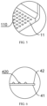
- FIG. 5 is an enlarged view of Place V in FIG. 3
- FIG. 6 is an enlarged view of Place VI in FIG. 4
- the first surface 11 has multiple grooves 110
- the adhesive layer (connector 40) has a second surface 41 and a third surface 42 opposite to each other in its thickness direction
- the second surface 41 is connected to the thermal management component 20
- the third surface 42 has multiple protrusions 420
- the protrusions 420 are embedded in the grooves 110.
- the groove 110 is a structure recessed from the first surface 11 into the battery cell 10 and also a structure for accommodating the protrusion 420.
- the protrusion 420 is a structure formed on the third surface 42 of the adhesive layer (connector 40).
- the protrusion 420 protrudes from the third surface 42 and is embedded in the groove 110.
- the non-protruding area of the third surface 42 is connected to the non-groove area of the first surface 11.
- the protrusions 420 on the third surface 42 of the adhesive layer (connector 40) are embedded in the grooves 110 on the first surface 11 of the battery cell 10, which can effectively improve the connection strength between the adhesive layer (connector 40) and the battery cell 10, thereby ensuring the connection strength between the battery cell 10 and the thermal management component 20, avoiding the debonding phenomenon occurring due to the self-expansion force of the battery cell 10 or the mechanical vibration of the battery cell 10, and ensuring that the thermal management component 20 is stably connected to the battery cell 10 to effectively adjust the temperature of the battery cell 10 and thereby ensure the safety of the battery.
- the multiple grooves 110 are in dense dot-like arrangement.
- the dense dot-like arrangement may refer to that the multiple dot-like grooves 110 are densely arranged on the first surface 11 according to a certain rule or irregularly.
- the "dot-like grooves 110" may mean that when looking directly at the first surface 11, each of the grooves 110 is non-strip-shaped, wherein the length and width of its opening are almost the same or the shape of its opening is in a shape of circle, triangle, quadrilateral, pentagon, etc.
- the number of grooves 110 is multiple, and the multiple grooves 110 are in dense dot-like arrangement, which, on the one hand, can effectively increase the bonding area between the first surface 11 and the adhesive layer (the connector 40) and on the other hand enable uniform stress between the first surface 11 and the adhesive layer (the connector 40).
- Each protrusion 420 is embedded in the corresponding groove 110, which can effectively improve the connection strength between the adhesive layer (connector 40) and the first surface 11, so that the thermal management component 20 is stably connected to the battery cell 10, ensuring the safety of the battery.
- the grooves 110 are tapered.
- the grooves 110 are tapered, referring to that a conical filler is filled in the grooves 110, or that the inner diameter of each of the grooves 110 gradually decreases from the opening of the groove 110 to the deepest part of the groove 110.
- the taped grooves 110 can be conveniently and quickly formed on the first surface 11 of the battery cell 10 by means of stamping, etc., so as to reduce the manufacturing difficulty of the battery cell 10.
- the adhesive solution is injected between the thermal management component 20 and the first surface 11, which can facilitate the filling of the adhesive solution in the groove 110 (the inner diameter of the groove 110 gradually decreases, so the adhesive solution is filled first in the part with a large inner diameter under the action of the injection pressure, and as the amount of the injected adhesive solution increases, gradually filled in the deep part with a small inner diameter, wherein since the inner diameter of the deep part is small, the filling amount is small, which can reduce the load of solution injection), to form the protrusions 420 when the adhesive solution is solidified (as shown in FIG. 6 ), and the protrusions 420 can be tightly bonded to the inner wall of the groove 110.
- the grooves 110 may be in a hemispherical shape, and correspondingly, the protrusions 420 may be in a hemispherical shape capable of being embedded and fitting in the grooves 110.
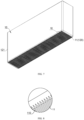
- FIG. 7 is a schematic view of a battery cell 10 in other embodiments of the present application
- FIG. 8 is an enlarged view of VIII in FIG. 7 .
- the grooves 110 extend in a first direction, multiple grooves 110 are arranged at intervals in a second direction, and the first direction is perpendicular to the second direction.
- the multiple grooves 110 are arranged at intervals in the second direction, and each groove 110 extends in the first direction, which can effectively improve the bonding area between the first surface 11 and the adhesive layer (connector 40), thereby ensuring the connection strength between the battery cell 10 and the thermal management component 20, preventing the thermal management component 20 from being separated from the battery cell 10, and ensuring the safety of the battery.
- the first surface 11 is a rectangular surface, one of the first direction and the second direction is the length direction of the first surface 11, and the other is the width direction of the first surface 11.
- the first surface 11 is a rectangular surface, one of the first direction and the second direction is the length direction of the first surface 11, and the other is the width direction of the first surface 11, so when machining the grooves 110, positioning may be performed based on the outer contour of the first surface 11, to reduce the difficulty in machining the grooves 110, thereby improving the manufacturing efficiency of the battery.
- the two ends of the groove 110 respectively extend to the edges of the first surface 11.
- That "the two ends of the groove 110 respectively extend to the edges of the first surface 11" may refer to that the groove 110 extends from one edge of the first surface 11 to another edge of the first surface 11, or, in other words, the two ends of the groove 110 both communicate with the outside, which is different from the solution in which the groove 110 is provided in the outer contour of the first surface 11 and the groove 110 does not communicate with the outside.
- the two ends of the groove 110 extend to the edges of the first surface 11.
- the groove 110 extends from one edge of the first surface 11 to another edge, which can reduce the difficult in shaping of the groove 110, and on the other hand, it facilitates injecting an adhesive solution (adhesive injection) into the groove 110 from the edge of the first surface 11, improves the efficiency of adhesive injection, and ensures that the groove 110 is full of the adhesive solution, so that the adhesive layer (connector 40) formed after the adhesive solution solidifies can be closely bonded to the inner wall of the groove 110 and the non-groove 110 area of the first surface 11 to ensure the connection strength between the adhesive layer (connector 40) and the battery cell 10.
- both ends of the groove 110 can be located within the outer contour of the first surface 11.
- FIG. 9 is a schematic view of the battery cell 10 and the adhesive layer (connector 40) in other embodiments of the present application
- FIG. 10 is an enlarged view of Place X in FIG. 9 .
- the cross-section of the groove 110 is triangular or rectangular.
- the cross-section of the groove 110 is triangular, which refers to that the cross-sectional shape of the groove 110 perpendicular to the extending direction of the groove 110 is triangular, the groove 110 has two mutually inclined inner walls.
- the cross-section of the protrusion 420 of the adhesive layer (connector 40) is also triangular, and the two inclined walls of the protrusion 420 of the adhesive layer (connector 40) are respectively corresponding to the two inner walls of the groove 110.
- the cross-section of the groove 110 is rectangular, which refers to that the cross-sectional shape of the groove 110 perpendicular to the extending direction of the groove 110 is rectangular.
- the groove 110 has a top wall and two parallel inner walls, and the two inner walls are connected to the top wall respectively.
- the cross-section of the protrusion 420 of the adhesive layer (connector 40) is also rectangular, and the three surfaces (two side walls and the top wall) of the protrusion 420 of the adhesive layer (connector 40) are respectively corresponding to the top wall and inner walls of the groove 110.
- the protrusion 420 when the cross-section of the groove 110 is triangular, the protrusion 420 is correspondingly triangular, and the two mutually inclined outer walls of the protrusion 420 are adhered to the two mutually inclined inner walls of the groove 110. That is, the two surfaces of the protrusion 420 are bonded to the two surfaces of the groove 110, which can increase the bonding area between the first surface 11 and the adhesive layer (connector 40).
- the cross-section of the groove 110 is rectangular
- the protrusion 420 is correspondingly rectangular, and the top wall and two opposite side walls of the protrusion 420 are respectively bonded to the top wall and the opposite side walls of the groove 110. That is, the three surfaces of the protrusion 420 are bonded to the three surfaces of the groove 110, which can effectively increase the bonding area between the first surface 11 and the adhesive layer (connector 40).
- the cross-section of the groove 110 may be semicircular, pentagonal or hexagonal, etc.
- the battery cell 10 includes a casing 12 and an end cover 13.
- the casing 12 includes a bottom wall 120 and a side wall 121, the side wall 121 surrounds the bottom wall 120, with one end of the side wall 121 being connected to the bottom wall 120, and the other end of the side wall 121 defining an opening, the end cover 13 covers the opening, and the first surface 11 is the outer surface of the bottom wall 120.
- the electrode assembly of the battery cell 10 is provided in the casing 12, and the end cover 13 covers the opening to seal the battery cell 10 in the casing 12.
- the first surface 11 is the outer surface of the bottom wall 120, which refers to that the surface of the bottom wall 120 away from the end cover 13 is the first surface 11, and the first surface 11 is a concave-convex surface, and also a surface bonded to the thermal management component 20 through the adhesive layer (connector 40).
- the thermal management component 20 is provided on the bottom wall 120 of the battery cell 10, and when the first surface 11 is the outer surface of the bottom wall 120, the connection strength between the bottom wall 120 and the adhesive layer (connector 40) can be improved, thereby improving the connection strength between the bottom wall 120 and the thermal management component 20, preventing the thermal management component 20 from being separated from the battery cell 10, and ensuring the safety of the battery.
- the first surface 11 is the outer surface of the bottom wall 120
- the concave-convex surface of the bottom wall 120 can reduce the chance of the battery cell 10 being in contact with a carrier during transportation and assembly, and reduce the probability of surface contamination.
- the outer surface of the bottom wall 120 of the battery cell 10 is the first surface 11, the cleaning process of the battery cell 10 before battery assembly may be omitted.
- the first surface 11 may also be the outer surface of the side wall 121 of the battery cell 10.
- the first surface 11 may be the outer surface of the side wall 121 of the battery cell 10, with a smaller area.
- Some embodiments of the present application further provide an electric device, including the battery provided in any one of the above embodiments, wherein the battery is used to provide electric energy.
- the battery includes a battery cell 10, a thermal management component 20 and a connector 40, wherein the connector 40 is an adhesive layer.
- the battery cell 10 includes a casing 12 and an end cover 13.
- the casing 12 includes a bottom wall 120 and a side wall 121.
- the side wall 121 surrounds the bottom wall 120.
- One end of the side wall 121 is connected to the bottom wall 120, and the other end of the side wall 121 defines an opening.
- the end cover 13 covers the opening, and the outer surface of the bottom wall 120 is the first surface 11.
- the thermal management component 20 is a water-cooled plate for accommodating a cooling liquid to adjust the temperature of the battery cell 10.
- the connector 40 is a component provided between the first surface 11 and the water-cooled plate, and is used for bonding the water-cooled plate to the first surface 11.
- the first surface 11 is provided as a concave-convex surface.
- the first surface 11 has multiple grooves 110.
- the connector 40 has a second surface 41 and a third surface 42 opposite to each other in its thickness direction, the second surface 41 is connected to the thermal management component 20, and the third surface 42 has multiple protrusions 420.
- the protrusions 420 are embedded in the grooves 110.
- the protrusions 420 are embedded in the grooves 110, a physical engagement effect is formed between the connector 40 and the first surface 11, which improves the anti-expansion force of the battery cell 10, thus avoiding occurrence of the situation in which the water-cooled plate is separated from the battery cell 10 which is caused by the debonding phenomenon occurring due to the expansion of the battery cell 10 (the connector 40 is separated from the first surface 11), and also improves the overall structural strength between the battery cell 10 and the water-cooled plate, thus avoiding the debonding phenomenon occurring due to mechanical vibration.
- the multiple grooves 110 are in dense dot-like arrangement. In some other cases, as shown in FIG. 8 and FIG.
- the grooves 110 extend along the width direction of the bottom wall 120, the multiple grooves 110 are arranged at intervals in the length direction of the bottom wall 120, and the two ends of each groove 110 respectively extend to the edges of the first surface 11.
- the cross-section of the groove 110 may be triangular or rectangular.
Landscapes
- Chemical & Material Sciences (AREA)
- Chemical Kinetics & Catalysis (AREA)
- Electrochemistry (AREA)
- General Chemical & Material Sciences (AREA)
- Engineering & Computer Science (AREA)
- Manufacturing & Machinery (AREA)
- Organic Chemistry (AREA)
- Battery Mounting, Suspending (AREA)
- Secondary Cells (AREA)
Abstract
Description
- The present application claims the priority to
Chinese patent application 202220903791.9, filed on April 19, 2022 - The present application relates to the field of battery technology, and in particular, to a battery and an electric device.
- Energy conservation and emission reduction are keys to the sustainable development of the automobile industry, and electric vehicles have become an important part of the sustainable development of the automobile industry, due to their advantages in energy conservation and environmental protection. For electric vehicles, battery technology is an important factor in its development.
- In the development of battery technology, how to improve the safety of batteries is a technical problem to be solved urgently in battery technology.
- The present application provides a battery and an electric device, which can improve the safety of the batteries.
- The present application is achieved through the following technical solutions.
- In a first aspect, the present application provides a battery, including: a battery cell; a thermal management component configured for accommodating fluid to adjust the temperature of the battery cell; a connector, provided between the thermal management component and the first surface of the battery cell and configured for making the thermal management component attached to the first surface, wherein the first surface is a concave-convex surface.
- In the technical solution of the embodiment of the present application, the first surface of the battery cell is provided as the concave-convex surface, which can increase the contact area between the first surface and the connector, avoid occurrence of the situation that the thermal management component is separated from the battery cell which is caused by the mutual separation phenomenon occurring due to expansion or mechanical vibration of the battery cell (the phenomenon that the connector is separated from the first surface due to expansion force or vibration), and ensure that the thermal management component is stably connected to the battery cell, so that the thermal management component can effectively adjust the temperature of the battery cell to ensure the safety of the battery.
- In some embodiments, the connector is an adhesive layer.
- In the technical solution of the embodiment of the present application, the thermal management component is bonded to the first surface of the battery cell through the adhesive layer. On the one hand, the assembly efficiency of the thermal management component and the battery cell can be improved, and on the other hand, since the first surface is the concave-convex surface, there is a larger bonding area between the adhesive layer and the battery cell, which can avoid occurrence of the situation that the thermal management component is separated from the battery cell which is caused by the debonding phenomenon occurring due to the expansion or mechanical vibration of the battery cell (the adhesive layer is separated from the first surface) and ensure that the thermal management component is stably connected to the battery cell, so that the thermal management component can effectively adjust the temperature of the battery cell to ensure the safety of the battery.
- In some embodiments, the first surface has multiple grooves, the adhesive layer has a second surface and a third surface opposite to each other in its thickness direction, the second surface is connected to the thermal management component, the third surface has multiple protrusions, and the protrusions are embedded in the grooves.
- In the technical solution of the embodiment of the present application, the protrusions on the third surface of the adhesive layer are embedded in the grooves on the first surface of the battery cell, which can effectively improve the connection strength between the adhesive layer and the battery cell, thereby ensuring the connection strength between the battery cell and the thermal management component, and avoid debonding phenomenon occurring due to the expansion force of the battery cell itself or the mechanical vibration of the battery cell, to ensure that the thermal management component is stably connected to the battery cell to effectively adjust the temperature of the battery cell and further ensure the safety of the battery.
- In some embodiments, the multiple grooves are in dense dot-like arrangement.
- In the technical solution of the embodiment of the present application, the number of the grooves is multiple, and the multiple grooves are in dot-like arrangement. On the one hand, it can effectively increase the bonding area between the first surface and the adhesive layer, and on the other hand, it can enable uniform force between the first surface and the adhesive layer. Each protrusion is embedded in the corresponding groove, which can effectively improve the connection strength between the adhesive layer and the first surface, so that the thermal management component is stably connected with the battery cell, ensuring the safety of the battery.
- In some embodiments, the groove is tapered.
- In the technical solution of the embodiment of the present application, tapered grooves can be conveniently and quickly formed on the first surface of the battery cell by means of stamping, etc., so as to reduce the difficulty in manufacturing of the battery cell. At the same time, when the grooves are tapered, the adhesive solution is injected between the thermal management component and the first surface, which can facilitate filling the adhesive solution into the grooves (the inner diameter of each of the grooves gradually decreases along its depth, so the adhesive solution is first filled in the portion with a large inner diameter, and as the amount of injected adhesive solution increases, it is gradually filled in the deep part with a small inner diameter, wherein since the inner diameter of the deep part is small, the filling amount is small, and the load of solution injection may be reduced), to form the protrusions after the adhesive solution is solidified. The stable connection between the thermal management component and the battery cell is achieved by tightly bonding the protrusions to the inner walls of the grooves.
- In some embodiments, the grooves extend in a first direction, the multiple grooves are arranged at intervals in a second direction, and the first direction is perpendicular to the second direction.
- In the technical solution of the embodiment of the present application, the multiple grooves are arranged at intervals in the second direction, and each groove extends in the first direction, which can effectively increase the bonding area between the first surface and the adhesive layer, thereby ensuring the connection strength between the battery cell and the thermal management component, avoiding that the thermal management component is separated from the battery cell and ensuring the safety of the battery.
- In some embodiments, the first surface is a rectangular surface, one of the first direction and the second direction is the length direction of the first surface, and the other is the width direction of the first surface.
- In the technical solution of the embodiment of the present application, since the first surface is a rectangular surface, one of the first direction and the second direction is the length direction of the first surface, and the other is the width direction of the first surface, positioning can be performed based on the outer contour of the first surface when processing the grooves, so as to reduce the difficulty in processing the grooves, thereby improving the manufacturing efficiency of the battery.
- In some embodiments, two ends of each groove respectively extend to edges of the first surface.
- In the technical solution of the embodiment of the present application, the two ends of each groove extend to the edges of the first surface. On the one hand, the groove extends from one edge of the first surface to another edge, which can reduce the difficulty in forming the groove, and on the other hand, it is convenient to inject the adhesive solution (adhesive injection) into the groove from the edge of the first surface, improve the efficiency of adhesive injection, and ensure that the groove is full of the adhesive solution, so that the adhesive layer formed after the solidification of the adhesive solution can be closely bonded to the inner wall of the groove and the non-groove area of the first surface, to ensure the connection strength between the adhesive layer and the battery cell.
- In some embodiments, the cross-section of the groove is triangular or rectangular.
- In the technical solution of the embodiment of the present application, when the cross-section of the groove is triangular, the protrusion is correspondingly triangular, and the two mutually inclined outer walls of the protrusion are bonded to the two mutually inclined inner walls of the groove, that is, two surfaces of the protrusion are bonded to the two surfaces of the groove, which can increase the bonding area between the first surface and the adhesive layer. When the cross-section of the groove is rectangular, the protrusion is correspondingly rectangular, and the top wall and two opposite side walls of the protrusion are bonded to the top wall and the opposite side walls of the groove respectively, that is, the three surfaces of the protrusion are bonded to the three surfaces of the groove, which can effectively increase the bonding area between the first surface and the adhesive layer.
- In some embodiments, the battery cell includes a casing and an end cover, wherein the casing includes a bottom wall and a side wall, the side wall surrounds the bottom wall, with one end of the side wall being connected to the bottom wall, and the other end of the side wall defining an opening, the end cover covers the opening, and the first surface is the outer surface of the bottom wall.
- In the technical solution of the embodiment of the present application, generally, the thermal management component is provided at the bottom wall of the battery cell. When the first surface is the outer surface of the bottom wall, the connection strength between the bottom wall and the connector can be improved, further improving the connection strength between the bottom wall and the thermal management component, avoiding the thermal management component from being separated from the battery cell, and ensuring the safety of the battery.
- In a second aspect, the present application further provides an electric device, including the battery according to any one of the first aspect, wherein the battery is used to provide electric energy.
- The above description is only an overview of the technical solution of the present application. In order to understand the technical solution of the present application more clearly, it can be implemented according to the contents of the description, and in order to make the above and other purposes, features and advantages of the present application more obvious and understandable, the following specifically cites the specific implementations of the present application.
- In order to more clearly illustrate the technical solutions of the embodiments of the present application, the following will briefly introduce the drawings required to be used in the embodiments. It should be understood that the following drawings only show some embodiments of the present application, and thus should not be regarded as a limitation on the scope, and those skilled in the art can also obtain other related drawings based on these drawings without paying creative work.
-
FIG. 1 is a schematic structural view of a vehicle in some embodiments of the present application; -
FIG. 2 is an exploded view of a battery in some embodiments of the present application; -
FIG. 3 is a three-dimensional exploded view of a battery cell, a connector and a thermal management component in some embodiments of the present application; -
FIG. 4 is a schematic view of a battery cell, a connector and a thermal management component in some embodiments of the present application; -
FIG. 5 is an enlarged view of Place V inFIG. 3 ; -
FIG. 6 is an enlarged view of Place VI inFIG. 4 ; -
FIG. 7 is a schematic view of a battery cell in other embodiments of the present application; -
FIG. 8 is an enlarged view of VIII inFIG. 7 ; -
FIG. 9 is a schematic view of a battery cell and a connector in other embodiments of the present application; and -
FIG. 10 is an enlarged view of Place X inFIG. 9 . - Reference signs: 10-battery cell; 11-first surface; 110-groove; 12-casing; 13-end cover; 120-bottom wall; 121-side wall; 20-thermal management component; 40-connector; 41-second surface; 42-third surface; 420-protrusion; 1000-vehicle; 100-battery; 200-controller; 300-motor; 30-box body; 3 1-first part; 32-second part.
- In order to make the purpose, technical solutions and advantages of the embodiments of the present application clearer, the technical solutions in the embodiments of the present application will be clearly described below in conjunction with the drawings in the embodiments of the present application. Obviously, the described embodiments are some but not all embodiments of the present application. Based on the embodiments in this application, all other embodiments obtained by those skilled in the art without paying creative efforts fall within the protection scope of the present application.
- Unless otherwise defined, all technical and scientific terms used in the present application have the same meaning as commonly understood by those skilled in the art of the present application. The terms used in the description of this application are only for the purpose of describing specific embodiments, rather than limiting the present application. The terms "comprising" and "having" and any variations thereof in the specification and claims of the present application and the description of the drawings above are intended to cover non-exclusive inclusion. The terms "first", "second" and the like in the specification and claims of the present application or the above drawings are used to distinguish different objects, rather than to describe a specific sequence or primary-subordinate relationship.
- Reference in this application to an "embodiment" means that a particular feature, structure, or characteristic described in connection with the embodiment may be included in at least one embodiment of the present application. This phrase occurring in various places in the specification are not necessarily all referring to the same embodiment, nor are separate or alternative embodiments mutually exclusive of other embodiments.
- In the description of this application, it should be noted that, unless otherwise clearly specified and defined, the terms "installation", "link", "connection" and "attachment" should be understood in a broad sense. For example, it may be fixed connection, it may also be detachable connection or integral connection, it may be direct connection or indirect connection through an intermediary, or it may be internal communication between two components. Those skilled in the art can understand the specific meanings of the above terms in the present application according to specific situations.
- The term "and/or" in the present application shows just an association relationship describing associated objects, which means that there may be three kinds of relationship. For example, A and/or B may indicate that: there is A, there are both A and B, and there is B. In addition, the character "/" in the present application generally indicates that the associated objects therebefore and thereafter have "or" relationship.
- In the embodiments of the present application, the same reference signs denote the same components, and for the sake of brevity, detailed descriptions of the same components are omitted in different embodiments. It should be understood that the thickness, length, width and other dimensions of the various components in the embodiments of the present application, as well as the overall thickness, length, width and other dimensions of the integrated device, shown in the drawings, are for illustrative description only, and should not constitute any limitation to the present application.
- The battery mentioned in the embodiments of the present application refers to a single physical module including one or more battery cells to provide higher voltage and capacity. The battery generally includes a box body used for packaging one or more battery cells. The box body can prevent liquid or other foreign objects from affecting the charging or discharging of the battery cell(s).
- "Multiple" in the present application refers to two or more (including two).
- In the present application, the battery cell may include lithium-ion battery, lithium-sulfur battery, sodium-lithium-ion battery, sodium-ion battery, or magnesium-ion battery, etc., which are not limited in the embodiments of the present application.
- The core component of the battery that can realize the repeated charging and discharging functions is the electrode assembly in the battery cell. The electrode assembly includes electrode plates and a separator. The electrode plates include a positive electrode plate and a negative electrode plate. The separator is usually arranged between the positive electrode plate and the negative electrode plate to insulate the positive electrode plate and the negative electrode plate from each other. The material of the separator may be PP (polypropylene) or PE (polyethylene), etc. The battery cell works mainly by moving metal ions between the positive electrode plate and negative electrode plate. In the above, the electrode plate includes a current collector and an active material layer. The current collector has a coating area coated with the active material layer and an uncoated area not coated with the active material layer, in the width direction of the electrode plate. The current collector not coated with the active material layer is cut to obtain tab(s), and the tab(s) realizes the charging and discharging of the electrode assembly. The current collector may be metal foil, such as copper foil, aluminum foil, and the like.
- At present, from the perspective of the development of the market situation, the electric vehicle has become an important part of the sustainable development of the automobile industry. The battery provides energy for the running of the vehicle body and the operation of various electric components in the vehicle body. Generally, a battery includes battery cell(s) and a thermal management component, the thermal management component is attached to the bottom wall of the battery cell(s) through a connector, and the thermal management component is used to accommodate a fluid (cooling liquid) to cool the battery cell(s), so that the battery cell(s) is subjected to charging and discharging at a safe temperature to ensure the safety of the battery. Generally, the surface of the bottom wall of each battery cell is a flat surface, and the connection strength between the thermal management component and the bottom wall of each battery cell is not high.
- Under the condition that the connection strength between the thermal management component and the bottom wall of each battery cell is not high, when the battery cell expands due to charging and discharging, wherein the expansion force makes the bottom wall of the battery cell deformed, causing separation of the connector between the bottom wall of the battery cell and the thermal management component, or the connector is separated from the battery cell due to the mechanical vibration of the battery (the battery vibrates under external force, for example, the vibration of the battery generated during transportation, or the vibration generated due to vehicle travelling when the battery is applied to the vehicle), thus causing the thermal management component and the battery cell to separate from each other, thereby affecting the ability that the thermal management component adjusts the temperature of the battery cell, and affecting the safety of the battery.
- Based on the above considerations, in order to ensure that the thermal management component is effectively connected to the battery cell and to ensure the safety of the battery, the inventors designed a battery through in-depth research, with the battery including the battery cell(s), the thermal management component and the connector. The thermal management component is used to accommodate a fluid to adjust the temperature of the battery cell(s). The connector is provided between the first surface(s) of the battery cell(s) and the thermal management component, and is used to make the thermal management component attached to the first surface(s). In the above, the first surface is a concave-convex surface.
- In the technical solution of the embodiment of the present application, the first surface of the battery cell is a concave-convex surface. Compared with the solution in which the first surface is a flat surface, the contact area between the first surface and the connector can be increased, and the connection strength between the first surface and the connector is improved, so as to avoid occurrence of the situation that the thermal management component is separated from the battery cell which is caused by the mutual separation phenomenon occurring due to expansion or mechanical vibration of the battery cell (the phenomenon that the connector is separated from the first surface due to expansion force or vibration), and ensure that the thermal management component is stably connected to the battery cell, so that the thermal management component can effectively adjust the temperature of the battery cell, thereby ensuring the safety of the battery.
- The technical solutions described in the embodiments of the present application are applicable to a battery and an electric device using the battery.
- The electric device may be a vehicle, a mobile phone, a portable device, a laptop, a ship, a spacecraft, an electric toy and an electric tool, etc. The vehicle may be new energy vehicle, and the new energy vehicle may be pure electric vehicle, hybrid power vehicle or extended-range vehicle, etc. The spacecraft includes airplane, rocket, space shuttle and spacecraft, etc. The electric toy includes fixed or mobile electric toy, for example, game console, electric car toy, electric ship toy and electric airplane toy, etc. The electric tool includes metal cutting electric tool, grinding electric tool, assembly electric tool and railway electric tool, for example, electric drill, electric grinder, electric wrench, electric screwdriver, electric hammer, impact electric drill, concrete vibrator and electric planer, etc. The embodiment of the present application does not specifically define the above electric devices.
- For the convenience of description, in the following embodiments, description is made by using a vehicle as an example of the electric device.
-
FIG. 1 is a schematic structural view of a vehicle in some embodiments of the present application. - A
controller 200, amotor 300 and abattery 100 may be provided inside thevehicle 1000, and thecontroller 200 is used to control thebattery 100 to supply power to themotor 300. For example, thebattery 100 may be provided at the bottom or head or tail of thevehicle 1000. Thebattery 100 may be used to supply power to the vehicle. For example, thebattery 100 may be used as an operating power source of thevehicle 1000, for a circuit system of thevehicle 1000, for example, for working power requirements during starting, navigating, and running of thevehicle 1000. In another embodiment of the present application, thebattery 100 can not only be used as an operating power source for thevehicle 1000, but also be used as a driving power source for thevehicle 1000, to replace or partially replace fuel oil or natural gas to provide driving power for thevehicle 1000. - Referring to
FIG. 2, FIG. 2 is an exploded view of a battery in some embodiments of the present application. - The
battery 100 includesbattery cells 10, abox body 30, and athermal management component 20. Thebattery cells 10 are accommodated in thebox body 30. Thethermal management component 20 is arranged on thebottom walls 120 of thebattery cells 10. Thethermal management component 20 is used to accommodate a fluid, wherein the fluid may be a medium for regulating the temperature of thebattery cells 10, such as cooling gas flow, cooling liquid, and the like. In the above, thebox body 30 is used to provide accommodation space for thebattery cells 10, and thebox body 30 may be in various structures. In some embodiments, thebox body 30 may include afirst part 31 and asecond part 32, wherein thefirst part 31 and thesecond part 32 cover each other, and thefirst part 31 and thesecond part 32 together define an accommodation space used for accommodating thebattery cells 10. Thesecond part 32 may be in a hollow structure with one end open, thefirst part 31 may be in a plate-shaped structure, and thefirst part 31 covers the opening side of thesecond part 32, so that thefirst part 31 and thesecond part 32 together define the accommodation space. Thefirst part 31 and thesecond part 32 may also each be in a hollow structure with one side open, and the opening side of thefirst part 31 covers the opening side of thesecond part 32. Of course, thebox body 30 formed by thefirst part 31 and thesecond part 32 may be in various shapes, such as cylinder, cuboid and so on. - In the
battery 100, there may be one ormore battery cells 10, and eachbattery cell 10 may be fixed to thebox body 30 by corresponding fasteners (such as bolts), or eachbattery cell 10 may be fixed to thebox body 30 by means of bonding. - In some embodiments of the present application, referring to
FIG. 3 and FIG. 4, FIG. 3 is a three-dimensional exploded view of thebattery cell 10, theconnector 40 and thethermal management component 20 in some embodiments of the present application, andFIG. 4 is schematic view of thebattery cell 10, theconnector 40 and thethermal management component 20 in some embodiments of the present application. - The battery includes a
battery cell 10, athermal management component 20 and aconnector 40. Thethermal management component 20 is used to accommodate a fluid to adjust the temperature of thebattery cell 10. Theconnector 40 is provided between thefirst surface 11 of thebattery cell 10 and thethermal management component 20, for making thethermal management component 20 attached to thefirst surface 11. In the above, thefirst surface 11 is a concave-convex surface. - The
first surface 11 is an end surface, of thebattery cell 10, connected to theconnector 40, and is also a surface of thebattery cell 10 that exchanges heat with thethermal management component 20. Thefirst surface 11 is a concave-convex surface, which means that thefirst surface 11 is not a flat surface, but is uneven. Compared with the solution in which it is a flat surface, it has a larger contact area with theconnector 40. Thethermal management component 20 is a component used for performing thermal management on the battery, which can exchange heat with the battery through a medium to control the temperature. Exemplarily, thethermal management component 20 may be a component for accommodating a fluid, and thethermal management component 20 may exchange heat with thebattery cell 10 through the fluid to adjust the temperature of thebattery cell 10, so as to ensure the safety of thebattery cell 10. For example, thethermal management component 20 may be a water-cooled plate, and the fluid accommodated therein is cooling liquid, wherein the heat of thebattery cell 10 generated due to charging and discharging is taken away by the cooling liquid. In addition, thethermal management component 20 may also be used to raise the temperature ofmultiple battery cells 10 by heating the fluid, which is not limited in this embodiment of the present application. - The
connector 40 is a component that makes thethermal management component 20 attached to thefirst surface 11 of thebattery cell 10. - In the technical solution of the embodiment of the present application, the
first surface 11 of thebattery cell 10 is a concave-convex surface. Compared with the solution in which thefirst surface 11 is a flat surface, on the one hand, the contact area between thefirst surface 11 and theconnector 40 can be increased, that is, the connection strength between thefirst surface 11 and theconnector 40 is increased, so as to avoid occurrence of the situation that thethermal management component 20 is separated from the battery cell which is caused by the mutual separation phenomenon occurring due to expansion or mechanical vibration of the battery cell 10 (the phenomenon that theconnector 40 is separated from the first surface due to expansion force or vibration), and ensure that thethermal management component 20 is stably connected to thebattery cell 10, so that thethermal management component 20 can effectively adjust the temperature of thebattery cell 10, thus ensuring the safety of the battery; and on the other hand, the heat exchange area between thethermal management component 20 and thebattery cell 10 can be increased, thereby improving the heat conduction efficiency between thethermal management component 20 and thebattery cell 10. - In some embodiments of the present application, the
connector 40 is an adhesive layer. - The adhesive layer, a component that connects the
battery cell 10 to thethermal management component 20, may be formed by solidifying an adhesive solution with adhesive property. For example, the adhesive layer is formed by injecting an adhesive solution between thefirst surface 11 of thebattery cell 10 and thethermal management component 20, and solidifying the adhesive solution. - In the technical solution of the embodiment of the present application, the
thermal management component 20 is bonded to thefirst surface 11 of thebattery cell 10 through the adhesive layer. On the one hand, the assembly efficiency of thethermal management component 20 and thebattery cell 10 can be improved. On the other hand, since thefirst surface 11 is a concave-convex surface, there is a large bonding area between the adhesive layer and thebattery cell 10, which can avoid occurrence of the situation that thethermal management component 20 is separated from thebattery cell 10 which is caused by the debonding phenomenon occurring due to the expansion or mechanical vibration of the battery cell (the adhesive layer is separated from the first surface 11), and ensure that thethermal management component 20 is stably connected to thebattery cell 10, so that thethermal management component 20 can effectively adjust the temperature of thebattery cell 10 to ensure the safety of the battery. - Optionally, in some other embodiments, the
connector 40 may also be other component capable of making thethermal management component 20 attached to thefirst surface 11 of thebattery cell 10. For example, the connector is a magic sticker (velcro tape) provided between thefirst surface 11 and thethermal management components 20. - In some embodiments of the present application, referring to
FIG. 4 ,FIG. 5 and FIG. 6, FIG. 5 is an enlarged view of Place V inFIG. 3 , andFIG. 6 is an enlarged view of Place VI inFIG. 4 . Thefirst surface 11 hasmultiple grooves 110, the adhesive layer (connector 40) has asecond surface 41 and athird surface 42 opposite to each other in its thickness direction, thesecond surface 41 is connected to thethermal management component 20, thethird surface 42 hasmultiple protrusions 420, and theprotrusions 420 are embedded in thegrooves 110. - The
groove 110 is a structure recessed from thefirst surface 11 into thebattery cell 10 and also a structure for accommodating theprotrusion 420. Theprotrusion 420 is a structure formed on thethird surface 42 of the adhesive layer (connector 40). Theprotrusion 420 protrudes from thethird surface 42 and is embedded in thegroove 110. The non-protruding area of thethird surface 42 is connected to the non-groove area of thefirst surface 11. - In the technical solution of the embodiment of the present application, the
protrusions 420 on thethird surface 42 of the adhesive layer (connector 40) are embedded in thegrooves 110 on thefirst surface 11 of thebattery cell 10, which can effectively improve the connection strength between the adhesive layer (connector 40) and thebattery cell 10, thereby ensuring the connection strength between thebattery cell 10 and thethermal management component 20, avoiding the debonding phenomenon occurring due to the self-expansion force of thebattery cell 10 or the mechanical vibration of thebattery cell 10, and ensuring that thethermal management component 20 is stably connected to thebattery cell 10 to effectively adjust the temperature of thebattery cell 10 and thereby ensure the safety of the battery. - In some embodiments of the present application, as shown in
FIG. 5 , themultiple grooves 110 are in dense dot-like arrangement. - The dense dot-like arrangement may refer to that the multiple dot-
like grooves 110 are densely arranged on thefirst surface 11 according to a certain rule or irregularly. The "dot-like grooves 110" may mean that when looking directly at thefirst surface 11, each of thegrooves 110 is non-strip-shaped, wherein the length and width of its opening are almost the same or the shape of its opening is in a shape of circle, triangle, quadrilateral, pentagon, etc. - In the technical solution of the embodiment of the present application, the number of
grooves 110 is multiple, and themultiple grooves 110 are in dense dot-like arrangement, which, on the one hand, can effectively increase the bonding area between thefirst surface 11 and the adhesive layer (the connector 40) and on the other hand enable uniform stress between thefirst surface 11 and the adhesive layer (the connector 40). Eachprotrusion 420 is embedded in thecorresponding groove 110, which can effectively improve the connection strength between the adhesive layer (connector 40) and thefirst surface 11, so that thethermal management component 20 is stably connected to thebattery cell 10, ensuring the safety of the battery. - In some embodiments of the present application, as shown in
FIG. 5 , thegrooves 110 are tapered. - The
grooves 110 are tapered, referring to that a conical filler is filled in thegrooves 110, or that the inner diameter of each of thegrooves 110 gradually decreases from the opening of thegroove 110 to the deepest part of thegroove 110. - In the technical solution of the embodiment of the present application, the taped
grooves 110 can be conveniently and quickly formed on thefirst surface 11 of thebattery cell 10 by means of stamping, etc., so as to reduce the manufacturing difficulty of thebattery cell 10. At the same time, when thegroove 110 is tapered, the adhesive solution is injected between thethermal management component 20 and thefirst surface 11, which can facilitate the filling of the adhesive solution in the groove 110 (the inner diameter of thegroove 110 gradually decreases, so the adhesive solution is filled first in the part with a large inner diameter under the action of the injection pressure, and as the amount of the injected adhesive solution increases, gradually filled in the deep part with a small inner diameter, wherein since the inner diameter of the deep part is small, the filling amount is small, which can reduce the load of solution injection), to form theprotrusions 420 when the adhesive solution is solidified (as shown inFIG. 6 ), and theprotrusions 420 can be tightly bonded to the inner wall of thegroove 110. - Optionally, in some embodiments, the
grooves 110 may be in a hemispherical shape, and correspondingly, theprotrusions 420 may be in a hemispherical shape capable of being embedded and fitting in thegrooves 110. - In other embodiments of the present application, referring to
FIG. 7 and FIG. 8, FIG. 7 is a schematic view of abattery cell 10 in other embodiments of the present application, andFIG. 8 is an enlarged view of VIII inFIG. 7 . Thegrooves 110 extend in a first direction,multiple grooves 110 are arranged at intervals in a second direction, and the first direction is perpendicular to the second direction. - In the technical solution of the embodiment of the present application, the
multiple grooves 110 are arranged at intervals in the second direction, and eachgroove 110 extends in the first direction, which can effectively improve the bonding area between thefirst surface 11 and the adhesive layer (connector 40), thereby ensuring the connection strength between thebattery cell 10 and thethermal management component 20, preventing thethermal management component 20 from being separated from thebattery cell 10, and ensuring the safety of the battery. - In other embodiments of the present application, the
first surface 11 is a rectangular surface, one of the first direction and the second direction is the length direction of thefirst surface 11, and the other is the width direction of thefirst surface 11. - In the technical solution of the embodiment of the present application, the
first surface 11 is a rectangular surface, one of the first direction and the second direction is the length direction of thefirst surface 11, and the other is the width direction of thefirst surface 11, so when machining thegrooves 110, positioning may be performed based on the outer contour of thefirst surface 11, to reduce the difficulty in machining thegrooves 110, thereby improving the manufacturing efficiency of the battery. - In other embodiments of the present application, as shown in
FIG. 8 , the two ends of thegroove 110 respectively extend to the edges of thefirst surface 11. - That "the two ends of the
groove 110 respectively extend to the edges of thefirst surface 11" may refer to that thegroove 110 extends from one edge of thefirst surface 11 to another edge of thefirst surface 11, or, in other words, the two ends of thegroove 110 both communicate with the outside, which is different from the solution in which thegroove 110 is provided in the outer contour of thefirst surface 11 and thegroove 110 does not communicate with the outside. - In the technical solution of the embodiment of the present application, the two ends of the
groove 110 extend to the edges of thefirst surface 11. On the one hand, thegroove 110 extends from one edge of thefirst surface 11 to another edge, which can reduce the difficult in shaping of thegroove 110, and on the other hand, it facilitates injecting an adhesive solution (adhesive injection) into thegroove 110 from the edge of thefirst surface 11, improves the efficiency of adhesive injection, and ensures that thegroove 110 is full of the adhesive solution, so that the adhesive layer (connector 40) formed after the adhesive solution solidifies can be closely bonded to the inner wall of thegroove 110 and the non-groove 110 area of thefirst surface 11 to ensure the connection strength between the adhesive layer (connector 40) and thebattery cell 10. - Optionally, in some embodiments, both ends of the
groove 110 can be located within the outer contour of thefirst surface 11. - In other embodiments of the present application, with reference to
FIG. 8 ,FIG. 9 and FIG. 10, FIG. 9 is a schematic view of thebattery cell 10 and the adhesive layer (connector 40) in other embodiments of the present application, andFIG. 10 is an enlarged view of Place X inFIG. 9 . The cross-section of thegroove 110 is triangular or rectangular. - The cross-section of the
groove 110 is triangular, which refers to that the cross-sectional shape of thegroove 110 perpendicular to the extending direction of thegroove 110 is triangular, thegroove 110 has two mutually inclined inner walls. Correspondingly, the cross-section of theprotrusion 420 of the adhesive layer (connector 40) is also triangular, and the two inclined walls of theprotrusion 420 of the adhesive layer (connector 40) are respectively corresponding to the two inner walls of thegroove 110. - The cross-section of the
groove 110 is rectangular, which refers to that the cross-sectional shape of thegroove 110 perpendicular to the extending direction of thegroove 110 is rectangular. Thegroove 110 has a top wall and two parallel inner walls, and the two inner walls are connected to the top wall respectively. Correspondingly, the cross-section of theprotrusion 420 of the adhesive layer (connector 40) is also rectangular, and the three surfaces (two side walls and the top wall) of theprotrusion 420 of the adhesive layer (connector 40) are respectively corresponding to the top wall and inner walls of thegroove 110. - According to the technical solution of the embodiment of the present application, when the cross-section of the
groove 110 is triangular, theprotrusion 420 is correspondingly triangular, and the two mutually inclined outer walls of theprotrusion 420 are adhered to the two mutually inclined inner walls of thegroove 110. That is, the two surfaces of theprotrusion 420 are bonded to the two surfaces of thegroove 110, which can increase the bonding area between thefirst surface 11 and the adhesive layer (connector 40). When the cross-section of thegroove 110 is rectangular, theprotrusion 420 is correspondingly rectangular, and the top wall and two opposite side walls of theprotrusion 420 are respectively bonded to the top wall and the opposite side walls of thegroove 110. That is, the three surfaces of theprotrusion 420 are bonded to the three surfaces of thegroove 110, which can effectively increase the bonding area between thefirst surface 11 and the adhesive layer (connector 40). - Optionally, the cross-section of the
groove 110 may be semicircular, pentagonal or hexagonal, etc. - In some embodiments of the present application, as shown in
FIG. 3 and FIG. 4 , thebattery cell 10 includes acasing 12 and anend cover 13. Thecasing 12 includes abottom wall 120 and aside wall 121, theside wall 121 surrounds thebottom wall 120, with one end of theside wall 121 being connected to thebottom wall 120, and the other end of theside wall 121 defining an opening, theend cover 13 covers the opening, and thefirst surface 11 is the outer surface of thebottom wall 120. - The electrode assembly of the
battery cell 10 is provided in thecasing 12, and theend cover 13 covers the opening to seal thebattery cell 10 in thecasing 12. Thefirst surface 11 is the outer surface of thebottom wall 120, which refers to that the surface of thebottom wall 120 away from theend cover 13 is thefirst surface 11, and thefirst surface 11 is a concave-convex surface, and also a surface bonded to thethermal management component 20 through the adhesive layer (connector 40). - According to the technical solution of the embodiment of the present application, generally, the
thermal management component 20 is provided on thebottom wall 120 of thebattery cell 10, and when thefirst surface 11 is the outer surface of thebottom wall 120, the connection strength between thebottom wall 120 and the adhesive layer (connector 40) can be improved, thereby improving the connection strength between thebottom wall 120 and thethermal management component 20, preventing thethermal management component 20 from being separated from thebattery cell 10, and ensuring the safety of the battery. At the same time, when thefirst surface 11 is the outer surface of thebottom wall 120, the concave-convex surface of thebottom wall 120 can reduce the chance of thebattery cell 10 being in contact with a carrier during transportation and assembly, and reduce the probability of surface contamination. Thus, when the outer surface of thebottom wall 120 of thebattery cell 10 is thefirst surface 11, the cleaning process of thebattery cell 10 before battery assembly may be omitted. - Optionally, the
first surface 11 may also be the outer surface of theside wall 121 of thebattery cell 10. For example, thefirst surface 11 may be the outer surface of theside wall 121 of thebattery cell 10, with a smaller area. - Some embodiments of the present application further provide an electric device, including the battery provided in any one of the above embodiments, wherein the battery is used to provide electric energy.
- Some embodiments of the present application also provide a battery, referring to
FIG. 3-FIG. 10 . The battery includes abattery cell 10, athermal management component 20 and aconnector 40, wherein theconnector 40 is an adhesive layer. Thebattery cell 10 includes acasing 12 and anend cover 13. Thecasing 12 includes abottom wall 120 and aside wall 121. Theside wall 121 surrounds thebottom wall 120. One end of theside wall 121 is connected to thebottom wall 120, and the other end of theside wall 121 defines an opening. The end cover 13 covers the opening, and the outer surface of thebottom wall 120 is thefirst surface 11. Thethermal management component 20 is a water-cooled plate for accommodating a cooling liquid to adjust the temperature of thebattery cell 10. Theconnector 40 is a component provided between thefirst surface 11 and the water-cooled plate, and is used for bonding the water-cooled plate to thefirst surface 11. In order to increase the bonding area between thefirst surface 11 and the water-cooled plate and ensure the connection strength between the water-cooled plate and thebattery cell 10, thefirst surface 11 is provided as a concave-convex surface. Thefirst surface 11 hasmultiple grooves 110. Theconnector 40 has asecond surface 41 and athird surface 42 opposite to each other in its thickness direction, thesecond surface 41 is connected to thethermal management component 20, and thethird surface 42 hasmultiple protrusions 420. Theprotrusions 420 are embedded in thegrooves 110. Since theprotrusions 420 are embedded in thegrooves 110, a physical engagement effect is formed between theconnector 40 and thefirst surface 11, which improves the anti-expansion force of thebattery cell 10, thus avoiding occurrence of the situation in which the water-cooled plate is separated from thebattery cell 10 which is caused by the debonding phenomenon occurring due to the expansion of the battery cell 10 (theconnector 40 is separated from the first surface 11), and also improves the overall structural strength between thebattery cell 10 and the water-cooled plate, thus avoiding the debonding phenomenon occurring due to mechanical vibration. In the above, in some cases, as shown inFIG. 5 , themultiple grooves 110 are in dense dot-like arrangement. In some other cases, as shown inFIG. 8 andFIG. 10 , thegrooves 110 extend along the width direction of thebottom wall 120, themultiple grooves 110 are arranged at intervals in the length direction of thebottom wall 120, and the two ends of eachgroove 110 respectively extend to the edges of thefirst surface 11. In this case, the cross-section of thegroove 110 may be triangular or rectangular. - The above are only preferred embodiments of the present application, and are not intended to limit the present application. For those skilled in the art, there may be various modifications and changes in the present application. Any modifications, equivalent replacements, improvements, etc., made within the spirit and principle of this application, shall be included within the protection scope of this application.
Claims (11)
- A battery, comprising:a battery cell;a thermal management component, configured for accommodating a fluid to adjust a temperature of the battery cell; anda connector, provided between a first surface of the battery cell and the thermal management component, and configured for making the thermal management component attached to the first surface,wherein the first surface is a concave-convex surface.
- The battery according to claim 1, wherein the connector is an adhesive layer.
- The battery according to claim 2, wherein the first surface has multiple grooves, the adhesive layer has a second surface and a third surface opposite to each other in a thickness direction thereof, the second surface is connected to the thermal management component, and the third surface is provided with multiple protrusions, wherein the protrusions are embedded in the grooves.
- The battery according to claim 3, wherein the multiple grooves are in dense dot-like arrangement.
- The battery according to claim 3 or 4, wherein the grooves are tapered.
- The battery according to claim 3 or 4, wherein the grooves extend in a first direction, the multiple grooves are arranged at intervals in a second direction, and the first direction is perpendicular to the second direction.
- The battery according to claim 6, wherein the first surface is a rectangular surface, one of the first direction and the second direction is a length direction of the first surface, and the other is a width direction of the first surface.
- The battery according to claim 6 or 7, wherein two ends of each of the grooves respectively extend to edges of the first surface.
- The battery according to any one of claims 6 to 8, wherein a cross-section of each of the grooves is triangular or rectangular.
- The battery according to any one of claims 1 to 9, wherein the battery cell comprises a casing and an end cover, the casing comprises a bottom wall and a side wall, the side wall surrounds the bottom wall, one end of the side wall is connected to the bottom wall, the other end of the side wall defines an opening, the end cover covers the opening, and the first surface is an outer surface of the bottom wall.
- An electric device, comprising the battery according to any one of claims 1 to 10, wherein the battery is configured to provide electric energy.
Applications Claiming Priority (2)
| Application Number | Priority Date | Filing Date | Title |
|---|---|---|---|
| CN202220903791.9U CN217009338U (en) | 2022-04-19 | 2022-04-19 | Battery and electric equipment |
| PCT/CN2022/101987 WO2023201884A1 (en) | 2022-04-19 | 2022-06-28 | Battery and electrical device |
Publications (2)
| Publication Number | Publication Date |
|---|---|
| EP4307441A1 true EP4307441A1 (en) | 2024-01-17 |
| EP4307441A4 EP4307441A4 (en) | 2024-11-20 |
Family
ID=82377952
Family Applications (1)
| Application Number | Title | Priority Date | Filing Date |
|---|---|---|---|
| EP22936038.3A Pending EP4307441A4 (en) | 2022-04-19 | 2022-06-28 | BATTERY AND ELECTRICAL DEVICE |
Country Status (4)
| Country | Link |
|---|---|
| US (1) | US20240014462A1 (en) |
| EP (1) | EP4307441A4 (en) |
| CN (1) | CN217009338U (en) |
| WO (1) | WO2023201884A1 (en) |
Families Citing this family (1)
| Publication number | Priority date | Publication date | Assignee | Title |
|---|---|---|---|---|
| CN222690733U (en) * | 2024-05-28 | 2025-03-28 | 宁德时代新能源科技股份有限公司 | Battery and electric equipment |
Family Cites Families (10)
| Publication number | Priority date | Publication date | Assignee | Title |
|---|---|---|---|---|
| KR100667946B1 (en) * | 2005-03-24 | 2007-01-11 | 삼성에스디아이 주식회사 | Secondary Battery and Its Case |
| CA3053807A1 (en) * | 2010-10-29 | 2012-05-03 | Dana Canada Corporation | Heat exchanger and battery unit structure for cooling thermally conductive batteries |
| JP2014130780A (en) * | 2012-12-28 | 2014-07-10 | Mitsubishi Heavy Ind Ltd | Battery module and battery unit |
| CN107464902B (en) * | 2017-07-28 | 2020-09-25 | 浙江吉利汽车研究院有限公司 | A battery pack cooling structure for a vehicle |
| CN107978698A (en) * | 2017-12-01 | 2018-05-01 | 合肥国盛电池科技有限公司 | Vehicular battery bag |
| CN115411404A (en) * | 2018-03-07 | 2022-11-29 | Sk新能源株式会社 | Battery module and method for manufacturing same |
| KR102825222B1 (en) * | 2019-08-13 | 2025-06-25 | 에스케이온 주식회사 | Secondary battery and battery module having thereof |
| JP7259721B2 (en) * | 2019-12-02 | 2023-04-18 | トヨタ自動車株式会社 | battery module |
| CN213584016U (en) * | 2020-07-10 | 2021-06-29 | 宁德时代新能源科技股份有限公司 | Batteries, electrical devices and devices for producing batteries |
| EP3958378B1 (en) * | 2020-07-10 | 2023-12-13 | Contemporary Amperex Technology Co., Limited | Battery, electric device, and method and device for preparing battery |
-
2022
- 2022-04-19 CN CN202220903791.9U patent/CN217009338U/en active Active
- 2022-06-28 WO PCT/CN2022/101987 patent/WO2023201884A1/en not_active Ceased
- 2022-06-28 EP EP22936038.3A patent/EP4307441A4/en active Pending
-
2023
- 2023-08-22 US US18/453,514 patent/US20240014462A1/en active Pending
Also Published As
| Publication number | Publication date |
|---|---|
| US20240014462A1 (en) | 2024-01-11 |
| CN217009338U (en) | 2022-07-19 |
| EP4307441A4 (en) | 2024-11-20 |
| WO2023201884A1 (en) | 2023-10-26 |
Similar Documents
| Publication | Publication Date | Title |
|---|---|---|
| CN219144442U (en) | Battery cell, battery and electricity utilization device | |
| CN115693049B (en) | Battery cell, battery and electricity utilization device | |
| CN215988963U (en) | Battery cell, battery and power consumption device | |
| CN218414960U (en) | Electrode assembly, battery cell, battery and electrical device | |
| CN216903136U (en) | Battery cells, batteries and electrical equipment | |
| CN217719660U (en) | Electrode assembly, battery cell, battery, and power consumption device | |
| CN219642994U (en) | Battery box, battery and power consumption device | |
| CN217768552U (en) | End cap assemblies, battery cells, batteries and electrical equipment | |
| EP4243167A1 (en) | Battery cell and battery, device, preparation method, and preparation device related thereto | |
| EP4542763A1 (en) | Battery cell, battery and electrical apparatus | |
| CN217768702U (en) | Battery cell, battery and power consumption device | |
| US20240014462A1 (en) | Battery and electric device | |
| CN217641563U (en) | End cover, battery monomer, battery and consumer | |
| CN216872173U (en) | Batteries and Electrical Equipment | |
| CN216213743U (en) | A battery cell, battery and electrical device | |
| JP7584622B2 (en) | Pressure relief devices, battery cells, batteries and electrical equipment | |
| US20240347824A1 (en) | End cover assembly, battery cell, battery, and electrical device | |
| EP4611130A1 (en) | Battery cell, battery and electric device | |
| WO2025066609A1 (en) | End cover assembly of battery cell, battery cell, battery, and electrical apparatus | |
| EP4447185A1 (en) | Electrode assembly, battery cell, battery and electric device | |
| EP4528879A1 (en) | Battery cell, battery and electric device | |
| CN217134568U (en) | Battery Modules, Batteries and Consumer Devices | |
| EP4597741A1 (en) | Battery cell, battery, and electrical device | |
| EP4510373A1 (en) | Battery cell, battery, and electrical device | |
| CN219017704U (en) | Pole piece, electrode assembly, battery cell, battery and electrical equipment |
Legal Events
| Date | Code | Title | Description |
|---|---|---|---|
| STAA | Information on the status of an ep patent application or granted ep patent |
Free format text: STATUS: UNKNOWN |
|
| STAA | Information on the status of an ep patent application or granted ep patent |
Free format text: STATUS: THE INTERNATIONAL PUBLICATION HAS BEEN MADE |
|
| PUAI | Public reference made under article 153(3) epc to a published international application that has entered the european phase |
Free format text: ORIGINAL CODE: 0009012 |
|
| STAA | Information on the status of an ep patent application or granted ep patent |
Free format text: STATUS: REQUEST FOR EXAMINATION WAS MADE |
|
| 17P | Request for examination filed |
Effective date: 20231009 |
|
| AK | Designated contracting states |
Kind code of ref document: A1 Designated state(s): AL AT BE BG CH CY CZ DE DK EE ES FI FR GB GR HR HU IE IS IT LI LT LU LV MC MK MT NL NO PL PT RO RS SE SI SK SM TR |
|
| RAP1 | Party data changed (applicant data changed or rights of an application transferred) |
Owner name: CONTEMPORARY AMPEREX TECHNOLOGY(HONG KONG) LIMITED |
|
| A4 | Supplementary search report drawn up and despatched |
Effective date: 20241017 |
|
| RIC1 | Information provided on ipc code assigned before grant |
Ipc: H01M 10/625 20140101ALI20241011BHEP Ipc: H01M 10/613 20140101ALI20241011BHEP Ipc: H01M 10/6556 20140101AFI20241011BHEP |
|
| DAV | Request for validation of the european patent (deleted) | ||
| DAX | Request for extension of the european patent (deleted) |