EP4306949A1 - Electrochemical gas sensor, ozone generator, and humidifier - Google Patents
Electrochemical gas sensor, ozone generator, and humidifier Download PDFInfo
- Publication number
- EP4306949A1 EP4306949A1 EP22767117.9A EP22767117A EP4306949A1 EP 4306949 A1 EP4306949 A1 EP 4306949A1 EP 22767117 A EP22767117 A EP 22767117A EP 4306949 A1 EP4306949 A1 EP 4306949A1
- Authority
- EP
- European Patent Office
- Prior art keywords
- ozone
- concentration
- gas
- detected
- sensing element
- Prior art date
- Legal status (The legal status is an assumption and is not a legal conclusion. Google has not performed a legal analysis and makes no representation as to the accuracy of the status listed.)
- Withdrawn
Links
- CBENFWSGALASAD-UHFFFAOYSA-N Ozone Chemical compound [O-][O+]=O CBENFWSGALASAD-UHFFFAOYSA-N 0.000 title claims description 407
- XLYOFNOQVPJJNP-UHFFFAOYSA-N water Chemical compound O XLYOFNOQVPJJNP-UHFFFAOYSA-N 0.000 claims abstract description 95
- 230000005856 abnormality Effects 0.000 claims description 59
- 230000009467 reduction Effects 0.000 claims description 47
- 230000008859 change Effects 0.000 claims description 19
- 230000035945 sensitivity Effects 0.000 claims description 18
- 238000013459 approach Methods 0.000 claims description 8
- 239000007789 gas Substances 0.000 description 308
- 238000006722 reduction reaction Methods 0.000 description 43
- 238000000034 method Methods 0.000 description 35
- 238000001514 detection method Methods 0.000 description 29
- 239000003595 mist Substances 0.000 description 22
- 238000002474 experimental method Methods 0.000 description 17
- 238000005259 measurement Methods 0.000 description 8
- 238000004891 communication Methods 0.000 description 7
- 230000004043 responsiveness Effects 0.000 description 6
- 230000000694 effects Effects 0.000 description 5
- 230000008569 process Effects 0.000 description 5
- 230000003321 amplification Effects 0.000 description 4
- 238000006243 chemical reaction Methods 0.000 description 4
- 238000012937 correction Methods 0.000 description 4
- 238000010586 diagram Methods 0.000 description 4
- 238000011156 evaluation Methods 0.000 description 4
- 239000007788 liquid Substances 0.000 description 4
- 238000003199 nucleic acid amplification method Methods 0.000 description 4
- 230000002159 abnormal effect Effects 0.000 description 3
- 238000007599 discharging Methods 0.000 description 3
- 238000005868 electrolysis reaction Methods 0.000 description 3
- 239000003792 electrolyte Substances 0.000 description 3
- 238000004519 manufacturing process Methods 0.000 description 3
- VGGSQFUCUMXWEO-UHFFFAOYSA-N Ethene Chemical compound C=C VGGSQFUCUMXWEO-UHFFFAOYSA-N 0.000 description 2
- 239000005977 Ethylene Substances 0.000 description 2
- 230000015556 catabolic process Effects 0.000 description 2
- 230000007423 decrease Effects 0.000 description 2
- 238000006731 degradation reaction Methods 0.000 description 2
- 230000010365 information processing Effects 0.000 description 2
- 230000002401 inhibitory effect Effects 0.000 description 2
- 238000005342 ion exchange Methods 0.000 description 2
- 230000002093 peripheral effect Effects 0.000 description 2
- 230000001105 regulatory effect Effects 0.000 description 2
- 239000011347 resin Substances 0.000 description 2
- 229920005989 resin Polymers 0.000 description 2
- 238000009834 vaporization Methods 0.000 description 2
- NWUYHJFMYQTDRP-UHFFFAOYSA-N 1,2-bis(ethenyl)benzene;1-ethenyl-2-ethylbenzene;styrene Chemical compound C=CC1=CC=CC=C1.CCC1=CC=CC=C1C=C.C=CC1=CC=CC=C1C=C NWUYHJFMYQTDRP-UHFFFAOYSA-N 0.000 description 1
- 229920003934 Aciplex® Polymers 0.000 description 1
- 229920003935 Flemion® Polymers 0.000 description 1
- YCKRFDGAMUMZLT-UHFFFAOYSA-N Fluorine atom Chemical compound [F] YCKRFDGAMUMZLT-UHFFFAOYSA-N 0.000 description 1
- 229920000557 Nafion® Polymers 0.000 description 1
- 239000004372 Polyvinyl alcohol Substances 0.000 description 1
- 241000700605 Viruses Species 0.000 description 1
- 230000002411 adverse Effects 0.000 description 1
- QVGXLLKOCUKJST-UHFFFAOYSA-N atomic oxygen Chemical compound [O] QVGXLLKOCUKJST-UHFFFAOYSA-N 0.000 description 1
- 230000004888 barrier function Effects 0.000 description 1
- 235000019504 cigarettes Nutrition 0.000 description 1
- 229920001577 copolymer Polymers 0.000 description 1
- 229910052731 fluorine Inorganic materials 0.000 description 1
- 239000011737 fluorine Substances 0.000 description 1
- 230000002209 hydrophobic effect Effects 0.000 description 1
- 230000000415 inactivating effect Effects 0.000 description 1
- 239000003014 ion exchange membrane Substances 0.000 description 1
- 239000003456 ion exchange resin Substances 0.000 description 1
- 229920003303 ion-exchange polymer Polymers 0.000 description 1
- 239000004973 liquid crystal related substance Substances 0.000 description 1
- 239000000463 material Substances 0.000 description 1
- 239000012528 membrane Substances 0.000 description 1
- 238000012986 modification Methods 0.000 description 1
- 230000004048 modification Effects 0.000 description 1
- 238000007254 oxidation reaction Methods 0.000 description 1
- 230000001590 oxidative effect Effects 0.000 description 1
- 239000001301 oxygen Substances 0.000 description 1
- 229910052760 oxygen Inorganic materials 0.000 description 1
- 238000003969 polarography Methods 0.000 description 1
- 229920001467 poly(styrenesulfonates) Polymers 0.000 description 1
- 229960002796 polystyrene sulfonate Drugs 0.000 description 1
- 239000011970 polystyrene sulfonate Substances 0.000 description 1
- 229920002451 polyvinyl alcohol Polymers 0.000 description 1
- 239000002994 raw material Substances 0.000 description 1
- 230000004044 response Effects 0.000 description 1
- 239000000779 smoke Substances 0.000 description 1
- 230000008016 vaporization Effects 0.000 description 1
Images




Classifications
-
- G—PHYSICS
- G01—MEASURING; TESTING
- G01N—INVESTIGATING OR ANALYSING MATERIALS BY DETERMINING THEIR CHEMICAL OR PHYSICAL PROPERTIES
- G01N27/00—Investigating or analysing materials by the use of electric, electrochemical, or magnetic means
- G01N27/26—Investigating or analysing materials by the use of electric, electrochemical, or magnetic means by investigating electrochemical variables; by using electrolysis or electrophoresis
- G01N27/403—Cells and electrode assemblies
- G01N27/404—Cells with anode, cathode and cell electrolyte on the same side of a permeable membrane which separates them from the sample fluid, e.g. Clark-type oxygen sensors
-
- C—CHEMISTRY; METALLURGY
- C01—INORGANIC CHEMISTRY
- C01B—NON-METALLIC ELEMENTS; COMPOUNDS THEREOF; METALLOIDS OR COMPOUNDS THEREOF NOT COVERED BY SUBCLASS C01C
- C01B13/00—Oxygen; Ozone; Oxides or hydroxides in general
- C01B13/10—Preparation of ozone
- C01B13/11—Preparation of ozone by electric discharge
-
- G—PHYSICS
- G01—MEASURING; TESTING
- G01N—INVESTIGATING OR ANALYSING MATERIALS BY DETERMINING THEIR CHEMICAL OR PHYSICAL PROPERTIES
- G01N33/00—Investigating or analysing materials by specific methods not covered by groups G01N1/00 - G01N31/00
- G01N33/0004—Gaseous mixtures, e.g. polluted air
- G01N33/0009—General constructional details of gas analysers, e.g. portable test equipment
- G01N33/0027—General constructional details of gas analysers, e.g. portable test equipment concerning the detector
- G01N33/0036—General constructional details of gas analysers, e.g. portable test equipment concerning the detector specially adapted to detect a particular component
- G01N33/0039—O3
-
- C—CHEMISTRY; METALLURGY
- C01—INORGANIC CHEMISTRY
- C01B—NON-METALLIC ELEMENTS; COMPOUNDS THEREOF; METALLOIDS OR COMPOUNDS THEREOF NOT COVERED BY SUBCLASS C01C
- C01B2201/00—Preparation of ozone by electrical discharge
- C01B2201/90—Control of the process
Definitions
- the present invention relates to an electrochemical gas sensor, an ozone generator, and a humidifier.
- Patent Document 1 discloses an example of an electrochemical gas sensor.
- the ozone sensor disclosed in Patent Document 1 is an electrochemical sensor in which diaphragm polarography is used, and quantifies ozone gas according to a magnitude of an electric current flowing between both electrodes: a working electrode and a counter electrode.
- Patent Document 2 discloses an example of an ozone generation apparatus.
- the ozone generation apparatus performs feedback control based on a signal from an external ozone sensor such that an external ozone concentration in a space outside the ozone generation apparatus becomes a target external ozone concentration.
- the present invention has been made in order to solve at least one of the above-described problems, and one of the objects is to provide a technique capable of more correctly detecting a concentration of a to-be-detected gas even when the concentration of the to-be-detected gas contained in a target gas is low.
- An electrochemical gas sensor is directed to a gas sensor for detecting a concentration of a to-be-detected gas contained in a target gas, and the electrochemical gas sensor includes:
- the electrochemical gas sensor is capable of cancelling influence of water vapor based on an output of the first sensing element and an output of the second sensing element and detecting the to-be-detected gas having a concentration of 0 or more and 1 ppm or less (parts per million).
- an electrochemical gas sensor when there is a difference in an amount of water vapor between inside and outside of the element, an electromotive force caused by the difference in the amount of water vapor may be generated, and an electric current caused by the difference in the amount of water vapor may flow.
- an electric current caused by the difference in the amount of water vapor may flow.
- influence of an electric current caused by difference in an amount of water vapor tends to be great when detecting the concentration of the to-be-detected gas.
- the first sensing element detects a concentration of a to-be-detected gas in a state in which the to-be-detected gas is substantially removed from a target gas, influence of an electric current caused by difference in an amount of water vapor can be evaluated.
- the second sensing element can detect a concentration of a target component containing water vapor and the to-be-detected gas.
- the electrochemical gas sensor can use the detection result of the first sensing element (result of evaluating influence of an electric current caused by difference in an amount of water vapor) for detecting a concentration of the to-be-detected gas by the second sensing element, which is advantageous in correctly detecting a concentration of a to-be-detected gas in a target gas in which the concentration of the to-be-detected gas is low. Therefore, even when a to-be-detected gas contained in a target gas has a low concentration of 1 ppm or less, the above-described electrochemical gas sensor can more correctly detect a concentration of the to-be-detected gas.
- substantially prevent permeation of the to-be-detected gas means that a permeation amount of the to-be-detected gas is 1/50 or less of a permeation amount of water vapor in terms of volume.
- the moisture permeable film may be a water vapor permeable filter that allows permeation of water vapor from the external space to the internal space and substantially prevents permeation of the to-be-detected gas from the external space to the internal space.
- a function of allowing permeation of water vapor from the external space to the internal space and substantially preventing permeation of the to-be-detected gas from the external space to the internal space can be achieved by the water vapor permeable filter.
- a thickness of the moisture permeable film may be more than 0 um and 60 um or less.
- the moisture permeable film is structured to have a thickness of 60 um or less, degradation of responsiveness with respect to change of a humidity can be further inhibited in the detection by the first sensing element.
- the electrochemical gas sensor may be preferably capable of detecting the to-be-detected gas having a concentration of 0 or more and 100 ppb or less (parts per billion).
- the electrochemical gas sensor can correctly evaluate influence of an "electric current caused by difference in an amount of water vapor" and detect a concentration of the to-be-detected gas by reflecting the evaluation result, so that the electrochemical gas sensor is very useful in a case where a target is gas in which the concentration of the to-be-detected gas is 100 ppb or less.
- the electrochemical gas sensor may include: a sensitivity setting portion configured to set a sensitivity based on a humidity of the target gas detected by a humidity sensor; and a concentration specifying portion configured to specify a concentration of the to-be-detected gas based on an output of the first sensing element, an output of the second sensing element, and the sensitivity.
- the humidity sensor may be configured as a part of the electrochemical gas sensor or may be a humidity sensor different from the electrochemical gas sensor.
- the to-be-detected gas may be ozone.
- An ozone generator may include the above-described electrochemical gas sensor in which the to-be-detected gas is ozone.
- the ozone generator can correctly detect a concentration of ozone in a simple configuration in addition to merely generating ozone.
- a humidifier may include the above-described electrochemical gas sensor.
- the humidifier can correctly detect a concentration of a to-be-detected gas in a simple configuration in addition to merely performing humidification.
- the ozone generator may include an ozone supply portion, a sensing portion, a controller, and an abnormality determination portion.
- the ozone supply portion may be configured to supply ozone to the external space.
- the sensing portion may be configured to electrochemically detect an ozone concentration, and may have the first sensing element and the second sensing element.
- the controller may be configured to perform first control for performing feedback control for the ozone supply portion such that an ozone concentration detected by the sensing portion approaches a target concentration, and second control for stopping the first control in a case where a determination criterion is satisfied during the first control.
- the abnormality determination portion may determine abnormality based on a degree of change from satisfaction of the determination criterion of an ozone concentration detected by the sensing portion until elapse of a predetermined period.
- the ozone generator when the first control is stopped, a degree of change of an ozone concentration detected by the sensing portion (detected concentration) varies depending on an actual ozone concentration. Therefore, based on the degree of change, the ozone generator can determine abnormality in which an actual ozone concentration during feedback control deviates from the target concentration.
- the controller may control the ozone supply portion so as to supply low-concentration ozone or stop the ozone supply portion.
- the abnormality determination portion may determine abnormality based on a degree of reduction from satisfaction of the determination criterion of an ozone concentration detected by the sensing portion until elapse of the predetermined period.
- abnormality can be determined while inhibiting increase of the ozone concentration in the external space.
- the abnormality determination portion may determine abnormality in a case where the degree of reduction is determined to be greater than a threshold value.
- abnormality in which an actual ozone concentration during feedback control becomes higher than a target concentration can be determined.
- the controller may perform the first control in a case where the degree of reduction is determined to be not greater than the threshold value, and may perform third control in a case where the degree of reduction is determined to be greater than the threshold value.
- the controller may perform feedback control for the ozone supply portion such that a concentration detected by the sensing portion approaches a second target concentration that is lower than the target concentration, or cause the ozone supply portion so as to supply low-concentration ozone, or stop the ozone supply portion is stopped.
- the first control is restarted, and, in a case where the degree of reduction is determined to be greater than the threshold value, supply of ozone can be reduced or stopped.
- the controller when the controller causes the ozone supply portion so as to supply low-concentration ozone in the third control, the controller may control the ozone supply portion such that the greater the degree of reduction is, the less a supply amount of ozone is.
- the ozone generator may include a humidifying portion for humidifying the external space.
- the ozone generator can also function as a humidifier.
- the concentration of the to-be-detected gas can be more correctly detected.
- An electrochemical gas sensor 10 illustrated in Fig. 1 is a gas sensor for detecting a concentration of a to-be-detected gas contained in a target gas.
- the electrochemical gas sensor 10 is simply referred to also as a gas sensor 10.
- the to-be-detected gas is ozone (ozone gas). That is, the gas sensor 10 illustrated in Fig. 1 functions as an ozone gas sensor for detecting a concentration of ozone gas.
- the gas sensor 10 mainly includes a sensing portion 12 and a controller 14.
- the sensing portion 12 includes an element portion 20 and an output circuit portion 16.
- the element portion 20 generates a first signal (voltage V1) as a signal for evaluating an "electric current caused by difference in an amount of water vapor" described above, and a second signal (voltage V2) as a signal corresponding to a concentration of a to-be-detected gas contained in the target gas.
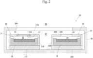
- the element portion 20 includes a first sensing element 21, a second sensing element 22, a first storage portion 31, a second storage portion 32, a first introduction inlet 31A, a second introduction inlet 32A, a moisture permeable film 24, a first waterproof filter 27, a second waterproof filter 28, and a case 30.
- the case 30 is a storage portion that stores the first storage portion 31, the second storage portion 32, the first sensing element 21, the second sensing element 22, and the like.
- the case 30 has an opening 30A that connects between a space 90 outside the case 30 and a space 92 inside the case 30.
- Fig. 2 illustrates an example of the opening 30A.
- the structure of the opening 30A is not limited as long as gas present in the space 90 outside the case 30 can be introduced into the space 92 inside the case 30.
- the first introduction inlet 31A and the second introduction inlet 32A are provided in the case 30.
- the first introduction inlet 31A and the second introduction inlet 32A may be provided in the space 90 outside the case 30. That is, a structure in which gas directly enters the moisture permeable film 24, the first waterproof filter 27, and the second waterproof filter 28 from the space 90, may be employed.
- the "target gas" containing a to-be-detected gas of which the concentration is to be detected by the gas sensor 10 is gas that is present in the space 90 outside the case 30 and that enters the space 92 inside the case 30 through the opening 30A formed in the case 30.
- gas in the spaces 90 and 92 corresponds to an example of the "target gas”.
- the spaces 90 and 92 each correspond to an example of an external space outside the first storage portion 31.
- the first storage portion 31 and the second storage portion 32 are disposed.
- the first storage portion 31 stores the first sensing element 21 thereinside.
- the first storage portion 31 has, in its own structure, an internal space 93 in which the first sensing element 21 is stored.
- the first storage portion 31 is in the form of a box that has a side wall portion 31B that surrounds the peripheral portion of the first sensing element 21, a bottom wall portion 31C that closes the lower side of the first sensing element 21, and an opening (the first introduction inlet 31A) formed in an upper portion.
- an upper wall portion 31D and the bottom wall portion 31C oppose each other in the up-down direction, the upper wall portion 31D is connected to the upper end portion of the side wall portion 31B, the bottom wall portion 31C is connected to the lower end portion of the side wall portion 31B, and the upper wall portion 31D has the above-described opening (first introduction inlet 31A) formed therein.
- first introduction inlet 31A the thickness direction of the moisture permeable film 24 described below is the up-down direction.
- the upper wall portion 31D side (side on which the first introduction inlet 31A is formed) is the upper side
- the bottom wall portion 31C side is the lower side.
- the first introduction inlet 31A is an opening formed in the first storage portion 31.
- the first introduction inlet 31A penetrates, in the up-down direction, the upper wall portion 31D forming a part of the first storage portion 31.
- the moisture permeable film 24 is a filter disposed in the first introduction inlet 31A.
- the moisture permeable film 24 is a film body that has a function of taking moisture in the external space (spaces 90, 92) thereinto (into the film), and guiding, to the internal space 93, moisture corresponding to the taken moisture, and that substantially does not allow permeation of a to-be-detected gas.
- the moisture permeable film 24 may be configured to take in moisture in the external space (spaces 90, 92), cause the moisture to pass through the moisture permeable film 24, and guide the moisture to the internal space 93.
- the moisture permeable film 24 may be configured to take in moisture in the external space (spaces 90, 92), perform ion exchange thereinside, and guide moisture generated by the ion exchange to the internal space 93.
- the moisture permeable film 24 polystyrene sulfonate, polyvinyl alcohol, vinyl alcohol copolymers, a fluorine-based ion exchange resin, a resin having a protic hydrophilic group in a repeating unit, a resin having an aprotic hydrophilic group in a repeating unit, or the like can be used.
- the fluororesin-based ion exchange membrane examples include Nafion (registered trademark), Flemion (registered trademark), and Aciplex (registered trademark).
- the moisture permeable film 24 may be used overlapping with a hydrophobic porous membrane. That is, any configuration may be used as long as an absolute humidity in the internal space 93 and an absolute humidity in the external space 92 can be made approximately equal to each other by presence of the moisture permeable film 24 disposed in the first introduction inlet 31A.
- the moisture permeable film 24 is formed by, for example, a water vapor permeable filter, and allows permeation of water vapor from the external space (spaces 90, 92) to the internal space 93, and substantially prevents permeation of ozone (ozone gas) from the external space (spaces 90, 92) to the internal space 93.
- ozone ozone gas
- a permeation amount of ozone gas is 1/50 or less of a permeation amount of water vapor in terms of volume.
- the moisture permeable film 24 is provided so as to close the first introduction inlet 31A. Therefore, gas entering the internal space 93 from the external space (spaces 90, 92) passes through the moisture permeable film 24 and enters the internal space 93.
- the thickness of the moisture permeable film 24 is preferably more than 0 um and 60 um or less. When the thickness of the moisture permeable film 24 is 60 um or less, the moisture permeable film 24 is advantageous in responsiveness.
- the thickness of the moisture permeable film 24 may be more preferably 30 um or less. When the thickness of the moisture permeable film 24 is 30 um or less, the moisture permeable film 24 is more advantageous in responsiveness. Meanwhile, the thickness of the moisture permeable film 24 is more preferably 1 um or more. When the thickness of the moisture permeable film 24 is 1 um or more, the moisture permeable film 24 is advantageous from the viewpoint of production.
- the thickness of the moisture permeable film 24 may be more preferably 5 um or more.
- the moisture permeable film 24 When the thickness of the moisture permeable film 24 is 5 um or more, the moisture permeable film 24 is more advantageous in production. For example, when the thickness of the moisture permeable film 24 is 1 um or more and 30 um or less, the moisture permeable film 24 is advantageous in production and responsiveness in a well-balanced manner.
- the first waterproof filter 27 is a filter that allows gas such as water vapor and ozone to pass therethrough, and substantially prevents liquid from passing therethrough.
- a permeation amount of liquid is 1/50 or less of a permeation amount of gas in terms of volume.
- the first waterproof filter 27 is provided so as to close the first introduction inlet 31A. Therefore, gas entering the internal space 93 from the external space (spaces 90, 92) passes through the first waterproof filter 27 and enters the internal space 93.
- the second storage portion 32 stores the second sensing element 22 thereinside.
- the second storage portion 32 has, in its own structure, an internal space 94 in which the second sensing element 22 is stored.
- the second storage portion 32 is in the form of a box that has a side wall portion 32B that surrounds the peripheral portion of the second sensing element 22, a bottom wall portion 32C that closes the lower side of the second sensing element 22, and an opening (the second introduction inlet 32A) formed in an upper portion.
- an upper wall portion 32D and the bottom wall portion 32C oppose each other in the up-down direction, the upper wall portion 32D is connected to the upper end portion of the side wall portion 32B, the bottom wall portion 32C is connected to the lower end portion of the side wall portion 32B, and the upper wall portion 32D has the above-described opening (second introduction inlet 32A) formed therein.
- the upper wall portion 32D side (side on which the second introduction inlet 32A is formed) is the upper side
- the bottom wall portion 32C side is the lower side.
- the second introduction inlet 32A is an opening formed in the second storage portion 32.
- the second introduction inlet 32A is a flow path that can function to introduce gas.
- the second introduction inlet 32A penetrates, in the up-down direction, the upper wall portion 32D forming a part of the second storage portion 32.
- the second introduction inlet 32A forms a route in which gas passes between the external space (space 90 or the space 92) outside the second storage portion 32 and the internal space 94 inside the second storage portion 32.
- the second waterproof filter 28 is a filter that allows gas such as water vapor and ozone to pass therethrough, and substantially prevents liquid from passing therethrough.
- a permeation amount of liquid is 1/50 or less of a permeation amount of gas in terms of volume.
- the second waterproof filter 28 is provided so as to close the second introduction inlet 32A. Therefore, gas entering the internal space 94 from the external space (spaces 90, 92) passes through the second waterproof filter 28 and enters the internal space 94.
- Each of the first sensing element 21 and the second sensing element 22 is an element that electrochemically causes an electric current corresponding to a concentration of ozone (ozone gas) to flow therethrough.
- each of the first sensing element 21 and the second sensing element 22 is also an element that generates an electromotive force corresponding to difference between an amount of water vapor inside the element and an amount of water vapor outside the element.
- the first sensing element 21 and the second sensing element 22 have the same configuration. In each of the first sensing element 21 and the second sensing element 22, when ozone gas is present in a space therearound, a reduction reaction occurs in its own detection electrode (not illustrated) and an oxidation reaction occurs in its own counter electrode (not illustrated).
- each of the first sensing element 21 and the second sensing element 22 also causes flow of an "electric current caused by difference in an amount of water vapor". Specifically, in the first sensing element 21 and the second sensing element 22, when there is a difference between an amount of water vapor in the gas flowing in from the space 92 and an amount of water vapor inside the element (space inside the element or electrolyte inside the element), an electric current corresponding to the difference is generated.
- an electric current corresponding to an ozone gas concentration in the internal space 93 and an electric current caused by difference in an amount of water vapor between inside and outside the first sensing element 21 flow between a detection electrode and a counter electrode thereof.
- the above-described reaction occurs in an electrolyte in the first sensing element 21 due to the ozone gas supplied to the first sensing element 21 via the internal space 93, and thereby an electric current corresponding to an ozone gas concentration flows, and, in addition to the electric current, an electric current caused by difference in an amount of water vapor between inside and outside the first sensing element 21 flows.
- the relationship between an ozone gas concentration in the internal space 93 and an "electric current corresponding to an ozone gas concentration" generated in the first sensing element 21 is specified by a predetermined arithmetic expression, and the higher an ozone gas concentration in the internal space 93 is, the higher an "electric current corresponding to the ozone gas concentration" generated in the first sensing element 21 is.
- flow of ozone gas into the internal space 93 is substantially prevented by the moisture permeable film 24. Therefore, in the first sensing element 21, an electric current corresponding to an ozone gas concentration does not flow, or even if the electric current flows, it is extremely low.
- an electric current corresponding to an ozone gas concentration in the internal space 94 and an electric current caused by difference in an amount of water vapor between inside and outside the second sensing element 22 flow between a detection electrode and a counter electrode thereof.
- the above-described reaction occurs in an electrolyte in the second sensing element 22 due to the ozone gas supplied to the second sensing element 22 via the internal space 94, and thereby an electric current corresponding to an ozone gas concentration flows, and, in addition to the electric current, an electric current caused by difference in an amount of water vapor between inside and outside the second sensing element 22 flows.
- the relationship between an ozone gas concentration in the internal space 94 and an "electric current corresponding to an ozone gas concentration" generated in the second sensing element 22 is specified by a predetermined arithmetic expression, and the higher an ozone gas concentration in the internal space 94 is, the higher an "electric current corresponding to the ozone gas concentration" generated in the second sensing element 22 is.
- the output circuit portion 16 includes a first output circuit 16A and a second output circuit 16B.
- the first output circuit 16A has resistances R11 and R12 and an operational amplifier OP1.
- Ra represents a resistance value of the resistance R11.
- Rb represents a resistance value of the resistance R12.
- the first output circuit 16A is a circuit that converts an electric current Ia (hereinafter, also referred to as output Ia) generated in the first sensing element 21 to a voltage Va, and outputs a voltage V1 obtained by amplifying the voltage Va at a predetermined amplification factor (Rb/Ra).
- the second output circuit 16B has resistances R21 and R22 and an operational amplifier OP2.
- Rc represents a resistance value of the resistance R21.
- Rd represents a resistance value of the resistance R22.
- the second output circuit 16B is a circuit that converts an electric current Ib (hereinafter, also referred to as output Ib) generated in the second sensing element 22 to a voltage Vb, and outputs a voltage V2 obtained by amplifying the voltage Vb at a predetermined amplification factor (Rd/Rc).
- a humidity sensor 15 is configured as, for example, an absolute humidity sensor that has a known configuration and detects an absolute humidity in the space 90. In Fig. 6 , the humidity sensor 15 is not illustrated. The humidity sensor 15 may be configured as a relative humidity sensor. The humidity sensor 15 may not necessarily be provided.
- the controller 14 illustrated in Fig. 1 is configured as an information processing device having a function of performing an arithmetic operation, an information processing function, a control function, and the like.
- the controller 14 includes an AD converter, an MCU (micro controller unit), and the like.
- the voltage V1 is inputted from the first output circuit 16A
- the voltage V2 is inputted from the second output circuit 16B.
- the controller 14 can convert the voltages V1 and V2 to digital signals, and can perform an arithmetic operation using the voltages V1 and V2.
- the first sensing element 21 and the second sensing element 22 are the same. In the first sensing element 21, an electric current caused by difference in an amount of water vapor (electric current corresponding to difference in an amount of water vapor between inside and outside the first sensing element 21) flows.
- the value of V2-V1 is a value obtained by cancelling influence of an "electric current caused by difference in an amount of water vapor" generated in the first sensing element 21 and the second sensing element 22, and is a voltage value corresponding to an ozone gas concentration in the space 92.
- the value of V2-V1 and an ozone gas concentration Y1 have such a correlation that the higher the ozone gas concentration Y1 in the space 92 is, the greater the value of V2-V1 is.
- the value of B is a predetermined fixed value (constant).
- the value of ⁇ may be a predetermined fixed value (constant), but may be a variable which is determined based on an absolute humidity. That is, the value of the gradient ⁇ in the relational expression (linear expression) may be corrected according to an absolute humidity.
- each of m and n represents a predetermined fixed value.
- ⁇ represents an absolute humidity of a target gas.
- ⁇ represents an absolute humidity detected in the spaces 90 and 92 by the humidity sensor 15.
- the relational expression when the value of ⁇ is ⁇ 1 is as represented by a linear line L1 illustrated in Fig. 3
- the relational expression can be adjusted as linear lines L2 and L3 by adjusting the value of ⁇ to ⁇ 2 and ⁇ 3.
- the value of ⁇ corresponds to an example of a sensitivity.
- the controller 14 corresponds to an example of a sensitivity setting portion, and sets a sensitivity ⁇ based on an absolute humidity ⁇ of a target gas detected by the humidity sensor 15.
- the controller 14 corresponds to an example of a concentration characteristic portion, and calculates the concentration Y1 of ozone gas (to-be-detected gas), according to the above-described relational expression and correction expression, based on the output Ia of the first sensing element 21, the output Ib of the second sensing element 22, and the sensitivity ⁇ .
- the calculated concentration Y1 may be adopted as the ozone gas concentration as it is, but it is desirable to apply a moving average assuming that delay in response may occur.
- a simple moving average may be calculated so as to obtain an average of the most recent n pieces of data (the concentrations Y1), and the value may be adopted as an ozone gas concentration.
- the gas sensor 10 can cancel influence of water vapor based on the output Ia of the first sensing element 21 and the output Ib of the second sensing element 22 to obtain the ozone gas concentration Y1.
- the value of V2-V1 is a value obtained by canceling influence of an "electric current caused by difference in an amount of water vapor" generated in the first sensing element 21 and the second sensing element 22, is a voltage value corresponding to an ozone gas concentration in the space 92, and is a value represented by the expression of Rb(Ib-Ia).
- the gas sensor 10 can cancel influence of water vapor based on difference (Ib-Ia) between the output Ia and the output Ib to detect an ozone gas concentration, and furthermore, can detect ozone gas that has a low concentration of 0 or more and 1 ppm or less. More specifically, the gas sensor 10 can detect ozone gas that has an extremely low concentration of 0 or more and 100 ppb or less.
- the gas sensor 10 having the same configuration as illustrated in Fig. 1 and Fig. 2 was prepared, and the element portion 20 of the gas sensor 10 was disposed in a room in which a humidity and a temperature were adjusted by an air conditioner.
- the ozone gas concentration Y1 was detected by the gas sensor 10 in the method described above in the first embodiment.
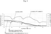
- the detection result of the concentration Y1 in Experiment 1 is represented by broken lines S3.
- the horizontal axis represents elapsed time (min (minutes)), and the vertical axis (first axis) represents the concentration (ppm) .
- an ozone gas concentration in a target space (room that was a space in which the concentration Y1 was detected) was detected by an analyzer (EBARA CORPORATION EG3000F) in parallel with the detection of the concentration Y1.
- the result of detecting the ozone gas concentration in the target space by the analyzer is represented by a thick line S2 in Fig. 4 .
- the detection result represented by the thick line S2 is represented according to the first axis on the left side and the horizontal axis.
- the detection result of the concentration Y1 by the gas sensor 10 in which the moisture permeable film 24 had a thickness of 12 um is represented by an alternate long and short dash line S5 in Fig. 5 .
- the detection result of the concentration Y1 by the gas sensor 10 in which the moisture permeable film 24 had a thickness of 60 um is represented by a solid line S6 in Fig. 5 .
- the horizontal axis represents elapsed time (min (minutes)) and the vertical axis represents the concentration (ppm).
- the period T1 may be considered to be a time period in which an absolute humidity rapidly changed without great change of the ozone gas concentration (that is, time period in which an amount of water vapor in the space rapidly changed).
- an electromotive force caused by the difference in the amount of water vapor may be generated, and an electric current caused by the difference in the amount of water vapor may flow.
- a concentration of a to-be-detected gas for example, ozone gas
- influence of an electric current caused by difference in an amount of water vapor tends to be great when detecting the concentration of the to-be-detected gas.
- the first sensing element 21 detects a concentration of a to-be-detected gas in a state in which the to-be-detected gas is substantially removed from a target gas, influence of an electric current caused by difference in an amount of water vapor can be evaluated.
- the second sensing element 22 can detect a concentration of a target component containing water vapor and the to-be-detected gas.
- the gas sensor 10 can use the detection result of the first sensing element 21 (result of evaluating influence of an electric current caused by difference in an amount of water vapor) for detecting a concentration of the to-be-detected gas by the second sensing element 22, which is advantageous in correctly detecting a concentration of a to-be-detected gas in a target gas in which the concentration of the to-be-detected gas is low. Therefore, even when a to-be-detected gas contained in a target gas has a low concentration of 1 ppm or less, the gas sensor 10 can more correctly detect a concentration of the to-be-detected gas.
- the moisture permeable film 24 when structured to have a thickness of 60 um or less, degradation of responsiveness with respect to change of a humidity can be further inhibited in the detection by the first sensing element.
- the gas sensor 10 is, more specifically, capable of detecting the to-be-detected gas having a concentration of 0 or more and 100 ppb or less.
- a concentration of the to-be-detected gas is 100 ppb or less
- influence of an "electric current caused by difference in an amount of water vapor" tends to be much greater when detecting the concentration of the to-be-detected gas.
- the gas sensor 10 can correctly evaluate influence of an "electric current caused by difference in an amount of water vapor" and detect a concentration of the to-be-detected gas by reflecting the evaluation result, so that the gas sensor 10 is very useful in a case where a target is gas in which the concentration of the to-be-detected gas is 100 ppb or less.
- the gas sensor 10 includes the controller 14 corresponding to an example of a concentration specifying portion, and can specify a concentration of the to-be-detected gas (ozone gas) based on outputs of the first sensing element 21 and the second sensing element 22, and the sensitivity ⁇ . Furthermore, the gas sensor 10 can adjust the sensitivity ⁇ based on an actually measured humidity of a target gas. Therefore, the sensitivity ⁇ can be made appropriate according to a humidity of a target gas obtained during detection.
- the to-be-detected gas is ozone (ozone gas).
- ozone ozone gas
- water vapor may become noise, and the ozone concentration may be hindered from being correctly detected.
- a target is gas in which a concentration of ozone is low
- influence of an "electric current caused by difference in an amount of water vapor” becomes relatively great, so that such a problem becomes more significant.
- the gas sensor 10 can correctly evaluate influence of an "electric current caused by difference in an amount of water vapor", and can use the evaluation for detecting a concentration of ozone. Therefore, the gas sensor 10 is extremely advantageous in correctly detecting an ozone concentration in a target gas in which an ozone concentration is low.
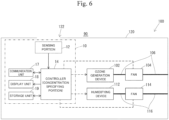
- Fig. 6 illustrates an ozone generator 100 including the gas sensor 10 described above.
- the ozone generator 100 has a humidifying function.
- the ozone generator 100 corresponds to an example of a humidifier, and has a function of humidifying the space 90 as the external space.
- the ozone generator 100 has the gas sensor 10, an ozone generation device 102, a fan 104, a humidifying device 112, a fan 114, and a case 120.
- the gas sensor 10 incorporated in the ozone generator 100 has a communication unit 17, a display unit 18, a storage unit 19, and the like as well as the sensing portion 12 and the controller 14 described above.
- the ozone generator 100 is configured such that an opening 122 is formed in the case 120, and gas outside the ozone generator 100 can be introduced into the sensing portion 12 through the opening 122. That is, a space outside the ozone generator 100 and the space 92 in the element portion 20 are connected with each other, and gas can mutually flow into and out of the spaces.
- the communication unit 17 is a unit for performing wired communication or wireless communication with an external device disposed outside the gas sensor 10.
- the communication unit 17 may be configured to communicate with a device in the ozone generator 100 or may be configured to communicate with a device outside the ozone generator 100.
- the display unit 18 is a unit for displaying symbols such as characters and numerals, and images such as pictures.
- the display unit 18 can display various information in cooperation with the controller 14.
- the storage unit 19 is a device for storing various information.
- the ozone generation device 102 is a device for generating ozone gas.
- Various known methods can be adopted as a method by which the ozone generation device 102 generates ozone (ozone gas).
- a known method such as an ultraviolet method, an electrolysis method, or an electric discharge method can be adopted.
- the ozone generation device 102 feeds ozone gas generated by itself to a supply tube 106.
- the supply tube 106 is a tube for guiding ozone gas generated by the ozone generation device 102 to a space outside the ozone generator 100. An amount and a flow rate of gas flowing through the supply tube 106 are adjusted by the fan 104.
- the fan 104 is configured as a blower (air sending machine).
- the fan 104 has, for example, a rotor (not illustrated) having a plurality of blades, a power unit (not-illustrated motor or the like) for rotating the rotor, and a drive circuit (not illustrated) for adjusting the rotation of the power unit.
- the drive circuit controls the number of revolutions of the rotor such that the number of revolutions of the rotor becomes the number of revolutions instructed by the controller 14. The greater the number of revolutions of the rotor of the fan 104 is, the greater an amount and a flow rate of gas flowing through the supply tube 106 are.
- the controller 14 can adjust a rate at which ozone gas is supplied (an amount of ozone gas supplied into a space per unit time) by adjusting the number of revolutions of the fan 104.
- the humidifying device 112 is a device for generating water vapor or mist.
- Various known methods can be adopted as a method by which the humidifying device 112 generates water vapor or mist.
- a known method such as a steam method, an ultrasonic method, a vaporization method, and a hybrid method can be adopted.
- the humidifying device 112 feeds water vapor or mist generated by itself to a supply tube 116.
- the supply tube 116 is a tube for guiding water vapor or mist generated by the humidifying device 112 to a space outside the ozone generator 100. An amount and a flow rate of gas flowing through the supply tube 116 are adjusted by the fan 114.
- the fan 114 is configured as a blower (air sending machine).
- the fan 114 has, for example, a rotor (not illustrated) having a plurality of blades, a power unit (not-illustrated motor or the like) for rotating the rotor, and a drive circuit (not illustrated) for adjusting the rotation of the power unit.
- the drive circuit controls the number of revolutions of the rotor such that the number of revolutions of the rotor becomes the number of revolutions instructed by the controller 14. The greater the number of revolutions of the rotor of the fan 114 is, the greater an amount and a flow rate of gas flowing through the supply tube 116 are.
- the controller 14 can adjust a rate at which water vapor or mist is supplied (an amount of water vapor or mist supplied into a space per unit time) by adjusting the number of revolutions of the fan 114.
- the controller 14 may display on the display unit 18 the detected ozone gas concentration Y1 (ozone gas concentration in a space in which the ozone generator 100 is disposed) as numerals, in cooperation with the display unit 18.
- the controller 14 may display on the display unit 18 an absolute humidity detected by the humidity sensor 15 (absolute humidity in a space in which the ozone generator 100 is disposed) as numerals.
- the controller 14 may display on the display unit 18 a relative humidity specified by the humidity sensor 15 (relative humidity in a space in which the ozone generator 100 is disposed).
- the controller 14 may transmit the detected ozone gas concentration Y1 to an external device disposed outside the ozone generator 100 in cooperation with the communication unit 17. Alternatively, the controller 14 may transmit the above-described absolute humidity or relative humidity to an external device disposed outside the ozone generator 100 in cooperation with the communication unit 17.
- the ozone generator 100 can actually measure an ozone concentration in the space accurately, and use the measured ozone concentration to enhance convenience for a user.
- the humidifier can not only merely humidify a space but also actually measure an ozone concentration in the space accurately, and use the measured ozone concentration to enhance convenience for a user.
- Fig. 7 illustrates an ozone generator 201 according to a second embodiment.
- the ozone generator 201 illustrated in Fig. 7 is a device for generating ozone and supplying the ozone to an external space 290 outside the ozone generator 201.
- the ozone generator 201 includes a case 203, an ozone supply portion 205, a humidifying portion 207, a sensing portion 210, a controller 212, an abnormality determination portion 214, an operation unit 216, and a display unit 218.
- the ozone supply portion 205, the humidifying portion 207, the sensing portion 210, the controller 212, the abnormality determination portion 214, the operation unit 216, and the display unit 218 are stored.
- a space outside the case 203 is a space outside the ozone generator 201, and is the external space 290.
- the case 203 has an opening 203A. Gas in the external space 290 can be introduced into the sensing portion 210 through the opening 203A.
- the ozone supply portion 205 generates ozone and supplies the generated ozone to the external space 290.
- the ozone supply portion 205 has an ozone generation device 205A, a fan 205B, and a supply tube 205C.
- the ozone generation device 205A is a device for generating ozone. A method by which the ozone generation device 205A generates ozone is not limited.
- the ozone generation device 205A has an AC power supply (not illustrated) such as a transformer, and an ozone generation unit (not illustrated).
- the AC power supply converts DC voltage to AC voltage.
- the ozone generation unit performs discharging (for example, dielectric barrier discharge) by being applied with AC voltage obtained through conversion by the AC power supply, and generates ozone by using, as a material, oxygen in a target gas (for example, air) introduced from the external space 290.
- An amount of ozone generated by the ozone generation device 205A is adjusted by adjusting voltage applied to the ozone generation device 205A (more specifically, an effective value of AC voltage applied to the ozone generation unit). The higher the voltage applied to the ozone generation unit (more specifically, an effective value of AC voltage applied to the ozone generation unit) is, the greater an amount of generated ozone is.
- the ozone generation device 205A feeds the ozone generated by itself to the supply tube 205C.
- the supply tube 205C is a tube for guiding ozone generated by the ozone generation device 205A to the external space 290. An amount and a flow rate of gas flowing through the supply tube 205C are adjusted by the fan 205B.
- the fan 205B is configured as a blower (air sending machine).
- the fan 205B has, for example, a rotor (not illustrated) having a plurality of blades, a power unit (not-illustrated motor or the like) for rotating the rotor, and a drive circuit (not illustrated) for adjusting the rotation of the power unit.
- the drive circuit controls the number of revolutions of the rotor such that the number of revolutions of the rotor becomes the number of revolutions instructed by the controller 212. The greater the number of revolutions of the rotor of the fan 205B is, the greater an amount and a flow rate of gas flowing through the supply tube 205C are.
- An amount of ozone supplied by the ozone supply portion 205 to the external space 290 is adjusted by adjusting at least one of voltage applied to the ozone generation device 205A and the number of revolutions of the fan 205B.
- the humidifying portion 207 supplies water vapor or mist to the external space 290 outside the ozone generator 201 and humidifies the external space 290.
- the humidifying portion 207 has a humidifying device 207A, a fan 207B, and a supply tube 207C.
- the humidifying device 207A is a device for generating water vapor or mist.
- Various known methods can be adopted as a method by which the humidifying device 207A generates water vapor or mist.
- a known method such as a steam method, an ultrasonic method, a vaporization method, and a hybrid method can be adopted.
- the humidifying device 207A feeds water vapor or mist generated by itself to the supply tube 207C.
- the supply tube 207C is a tube for guiding water vapor or mist generated by the humidifying device 207A to the external space 290 outside the ozone generator 201. An amount and a flow rate of gas flowing through the supply tube 207C are adjusted by the fan 207B.
- the fan 207B is configured as a blower (air sending machine).
- the fan 207B has, for example, a rotor (not illustrated) having a plurality of blades, a power unit (not-illustrated motor or the like) for rotating the rotor, and a drive circuit (not illustrated) for adjusting the rotation of the power unit.
- the drive circuit controls the number of revolutions of the rotor such that the number of revolutions of the rotor becomes the number of revolutions instructed by the controller 212. The greater the number of revolutions of the rotor of the fan 207B is, the greater an amount and a flow rate of gas flowing through the supply tube 207C are.
- the controller 212 can adjust a rate at which water vapor or mist is supplied (an amount of water vapor or mist supplied to the external space 290 per unit time) by adjusting the number of revolutions of the fan 207B.
- the sensing portion 210 is an ozone sensor for electrochemically detecting an ozone concentration.
- the "electrochemically” means, for example, a potentiostatic electrolysis method.
- the sensing portion 210 detects an ozone concentration in air introduced from the external space 290.
- a signal indicating an ozone concentration detected by the sensing portion 210 (hereinafter, also referred to as "detected concentration") is inputted to each of the controller 212 and the abnormality determination portion 214.
- the configuration of the sensing portion 210 may be the same as the configuration of the sensing portion 12 of the first embodiment, or may be different from the configuration of the sensing portion 12. In a typical example, the sensing portion 210 has the same configuration as the sensing portion 12, and has the first sensing element 21, the second sensing element 22, and the like.
- Each of the controller 212 and the abnormality determination portion 214 is, for example, composed of a microcomputer as a main unit, and has a CPU, a ROM, a RAM, and the like.
- the controller 212 controls operations of the ozone supply portion 205, the humidifying portion 207, and the display unit 218.
- the operation unit 216 is, for example, a push switch.
- the display unit 218 is, for example, a LED lamp, a liquid crystal display, or the like.
- the controller 212 performs first control for performing feedback control for the ozone supply portion 205 such that an ozone concentration detected by the sensing portion 210 approaches a target concentration.
- the target concentration may be a predetermined fixed value, or may be a value that is set through a setting operation performed by using the operation unit 216.
- the target concentration is preferably high from the viewpoint of inactivating virus floating in the external space 290, but is preferably set so as not to adversely affect human bodies.
- the target concentration is preferably more than 0 ppb (parts per billion) and 100 ppb or less. In the present embodiment, the target concentration is 50 ppb.
- the controller 212 performs feedback control for the ozone supply portion 205 in the first control by adjusting for example, voltage to be applied to the ozone generation device 205A of the ozone supply portion 205.
- the number of revolutions of the rotor of the fan 205B is constant. However, the number of revolutions of the rotor of the fan 205B may vary.
- the controller 212 performs second control for stopping the first control.
- the determination criterion is not particularly limited.
- the determination criterion may be, for example, a condition in which a second predetermined period (for example, 120 minutes) has elapsed from the start of the first control.
- the second predetermined period may be a predetermined fixed value, may vary according to an ozone concentration or the like, or may be a value that is set through a setting operation performed by using the operation unit 216.
- the second predetermined period may be determined based on an assumed upper limit value of an ozone concentration during the first control.
- the second predetermined period may be shorter than 200 minutes (for example, 120 minutes) by which human bodies are not affected even if the state of 160 ppb continues.
- Another example of the determination criterion may be a condition in which a determination operation has been performed by the operation unit 216.
- the second control is, for example, control for supplying a constant amount of ozone, control for supplying ozone with regular change, or control for stopping the ozone supply portion 205.
- the controller 212 controls the ozone supply portion 205 so as to supply low-concentration ozone, or stops the ozone supply portion 205. That is, in the second control, for example, the controller 212 controls the ozone supply portion 205 so as to supply a constant amount of low-concentration ozone, controls the ozone supply portion 205 so as to supply low-concentration ozone with regular change, or stops the ozone supply portion 205.
- the "low concentration” means that an amount is less than an amount of ozone supplied from the ozone supply portion 205 when the determination criterion is satisfied during the first control, and may be a "predetermined value” or may be a "value determined based on a detected concentration".
- the "predetermined value” may be, for example, a value less than an ozone supply amount required to maintain an actual concentration at a target concentration in an environment where there is no influence of gas other than ozone.
- the "value determined based on a detected concentration” may be, for example, 30% or less of an amount of ozone that is supplied from the ozone supply portion 205 when the determination criterion is satisfied during the first control.
- an amount of ozone supplied from the ozone supply portion 205 has a correlation with voltage applied to the ozone supply portion 205, and thus can be compared with voltage that is applied to the ozone supply portion 205 when the determination criterion is satisfied during the first control.
- the controller 212 can set an amount of ozone supplied from the ozone supply portion 205 to 30% or less by setting the voltage applied to the ozone supply portion 205 to be 30% or less of the voltage that is applied to the ozone supply portion 205 when the determination criterion is satisfied during the first control.
- the abnormality determination portion 214 determines abnormality based on a degree of change from satisfaction of the determination criterion of the ozone concentration detected by the sensing portion 210 until elapse of a predetermined period.
- the "abnormality” means “abnormality in which an actual ozone concentration during feedback control deviates from a target concentration”.
- the sensing portion 210 which electrochemically detects an ozone concentration as described above is also influenced by gas other than ozone.
- the reducing gas affects in the minus direction with respect to the detection result by the sensing portion 210 which electrochemically detects an ozone concentration.
- the detected concentration is lower than the actual ozone concentration (hereinafter, also referred to as "actual concentration").
- the abnormality determination portion 214 can determine abnormality that occurs in this way.
- the predetermined period is a period determined in advance and is, for example, 10 minutes.
- the abnormality determination portion 214 determines abnormality based on the degree of reduction from satisfaction of the determination criterion of the detected concentration until elapse of the predetermined period, in the configuration where the controller 212 controls the ozone supply portion 205 so as to supply low-concentration ozone or stops the ozone supply portion 205 in the second control.
- the controller 212 controls the ozone supply portion 205 so as to supply low-concentration ozone or stops the ozone supply portion 205 in the second control
- the detected concentration decreases during the second control.
- the abnormality determination portion 214 determines abnormality in a case where the degree of reduction is determined to be greater than a threshold value. As described above, in a case where there is a reducing gas, the actual concentration tends to be higher than the target concentration in the first control. The higher the actual concentration is, the greater the degree of reduction when the second control is performed is. Therefore, in a case where there is a reducing gas, the degree of reduction becomes great when the second control is performed, as compared with a case where there is no reducing gas (that is, in a case where the actual concentration is equal to the target concentration).
- the abnormality determination portion 214 previously grasps a degree of reduction when the predetermined period elapses in a case where an actual concentration when the determination criterion is satisfied is an abnormal value, and thereby can determine abnormality.
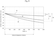
- Fig. 8 illustrates graphs G1, G2, G3 based on actually measured values.
- G1 represents an ozone concentration changing with elapse of time when the second control (in this case, stop of the ozone supply portion 205) is performed in a state where the actual concentration is equal to a target concentration (50 ppb).
- G2 represents an ozone concentration changing with elapse of time when the second control is performed in a state where an actual concentration is 100 ppb.
- G3 represents an ozone concentration changing with elapse of time when the second control is performed in a state where an actual concentration is 130 ppb.
- C1 represents a degree of reduction from start of the second control until elapse of the predetermined period in a state where the actual concentration is equal to the target concentration.
- C2 represents a degree of reduction from start of the second control until elapse of the predetermined period in a state where the actual concentration is 100 ppb.
- C3 represents a degree of reduction from start of the second control until elapse of the predetermined period in a state where the actual concentration is 130 ppb.
- the above-described "threshold value" is greater than a value of C1, and is C2 in the present embodiment.
- the degree of reduction is greater than C2 which serves as the threshold value. Therefore, the abnormality determination portion 214 determines that the degree of reduction is greater than the threshold value, and determines that it is abnormal.
- the degree of reduction is not greater than C2 which serves as the threshold value. Therefore, the abnormality determination portion 214 determines that the degree of reduction is not greater than the threshold value, and does not determine that it is abnormal.
- the controller 212 performs the first control in a case where the degree of reduction is determined to be not greater than the threshold value, and, the controller 212 performs third control in a case where the degree of reduction is determined to be greater than the threshold value.
- the third control is a control for performing feedback control for the ozone supply portion 205 such that the detected concentration approaches a second target concentration lower than the target concentration, or causing the ozone supply portion 205 to supply low-concentration ozone, or stopping the ozone supply portion 205.
- the third control may be control different from the second control, or may be the same control as the second control. That is, the controller 212 may change or may not change contents of the control when shifting from the second control to the third control.
- the ozone supply portion 205 may be stopped in the second control, and the ozone supply portion 205 may be caused to supply low-concentration ozone in the third control.
- the ozone supply portion 205 may be controlled so as to supply low-concentration ozone in the second control, and the ozone supply portion 205 may be maintained so as to supply low-concentration ozone in the third control.
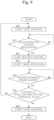
- the start criterion is, for example, that a starting operation is performed by the operation unit 216.
- the controller 212 starts the above-described first control in step S10. After the first control has been started, the controller 212 determines in step S11 whether or not the above-described determination criterion has been satisfied. In a case where the controller 212 determines that the determination criterion is not satisfied (in the case of No in step S11), the process is returned to step S11. That is, the controller 212 repeatedly determines whether or not the determination criterion is satisfied until the determination criterion is satisfied.
- the controller 212 determines that the determination criterion has been satisfied (in the case of Yes in step S11), the controller 212 stops the first control and starts the second control in step S12.
- the abnormality determination portion 214 starts an operation of a timer in step S13.
- the abnormality determination portion 214 determines in step S14 whether or not a predetermined period has elapsed based on the timer operated in step S13. In a case where the abnormality determination portion 214 determines that the predetermined period has not elapsed (in the case of No in step S14), the process is returned to step S14. That is, the abnormality determination portion 214 repeatedly determines whether or not the predetermined period has elapsed until the predetermined period has elapsed.
- the abnormality determination portion 214 determines in step S15 whether or not the degree of reduction of the detected concentration is greater than a threshold value. In a case where the abnormality determination portion 214 determines that the degree of reduction of the detected concentration is not greater than the threshold value (in the case of No in step S15), the controller 212 returns the process to step S10 to stop the second control and start the first control. In a case where the abnormality determination portion 214 determines that the degree of reduction of the detected concentration is greater than the threshold value (in the case of Yes in step S15), the controller 212 stops the second control and starts the third control in step S16.
- the controller 212 performs the second control. Then, in a case where the degree of reduction of the detected concentration is not greater than the threshold value, the controller 212 restarts the first control, and, in a case where the degree of reduction of the detected concentration is greater than the threshold value, the controller 212 causes the ozone supply portion 205 so as to supply low-concentration ozone or stops the ozone supply portion 205.
- the sensing portion 210 electrochemically detects an ozone concentration, and may thus be influenced by gas (for example, cigarette smoke or incense) other than ozone. As a result, the detected concentration may deviate from an actual concentration. If feedback control is performed for the ozone supply portion 205 in this state such that the detected concentration approaches a target concentration, the actual concentration deviates from the target concentration. In order to determine such abnormality, the ozone generator 201 performs the second control for stopping the first control in a case where the determination criterion is satisfied during the first control. The ozone generator 201 determines abnormality based on the degree of change of the detected concentration from satisfaction of the determination criterion until elapse of a predetermined period.
- gas for example, cigarette smoke or incense
- the sensing portion 210 which electrochemically detects an ozone concentration has characteristics that, the higher the actual concentration is, the more the detected concentration tends to decrease. Therefore, when the first control has been stopped, a degree of change of the detected concentration varies according to the actual concentration. Based on the degree of the change, the ozone generator 201 can determine abnormality in which the actual concentration during feedback control deviates from a target concentration.
- the ozone generator 201 controls the ozone supply portion 205 so as to supply low-concentration ozone or stops the ozone supply portion 205, and determines abnormality based on the degree of reduction of the detected concentration from satisfaction of the determination criterion until elapse of a predetermined period. Therefore, the ozone generator 201 can determine abnormality while inhibiting increase of the ozone concentration in the external space 290.
- the ozone generator 201 determines abnormality in a case where the degree of reduction is determined to be greater than a threshold value. Therefore, the ozone generator 201 can determine abnormality in which an actual ozone concentration during feedback control becomes higher than a target concentration.
- the ozone generator 201 restarts the first control, and, in a case where the degree of reduction is determined to be greater than the threshold value, the ozone generator 201 can reduce or stop supply of ozone.
- the ozone generator 201 includes the humidifying portion 207. Therefore, the ozone generator 201 can also function as a humidifier.
- the gas sensor 10 in which a to-be-detected gas is ozone gas is described.
- the to-be-detected gas of the gas sensor 10 may be gas other than ozone gas.
- ethylene gas may be the to-be-detected gas.
- the gas sensor 10 may function as an ethylene gas sensor.
- the ozone generation device 102 and the humidifying device 112 are configured as separate devices.
- the ozone generation device 102 and the humidifying device 112 may be configured integrally. That is, the ozone generation device 102 may have a humidifying function of discharging water vapor or mist.
- the fan 114 may be omitted, and the fan 104 may be used to adjust a supply rate of ozone and a supply rate of water vapor or mist.
- the present invention is not limited to this example.
- a method in which a flow rate is adjusted by a flow rate regulating valve may be adopted, or, an ozone supply state and an ozone supply stop state may be switched simply by opening/closing a flow path by an on-off valve.
- the ozone generator 100 may adjust supply of ozone by switching between a state in which the ozone generation device 102 is operated and a state in which the operation is stopped, without providing the fan 104 or using the fan 104 in combination.
- the present invention is not limited to this example.
- a method in which a flow rate is adjusted by a flow rate regulating valve may be adopted, or, a state in which water vapor or mist is supplied and a state in which the supply is stopped may be switched simply by opening/closing a flow path by an on-off valve.
- the ozone generator 100 may adjust supply of water vapor or mist by switching between a state in which the humidifying device 112 is operated and a state in which the operation is stopped, without providing the fan 114 or using the fan 114 in combination.
- the ozone generator 100 having a humidifying function is described as an example of an ozone generator.
- an ozone generator having no humidifying function may include the gas sensor 10.
- One of the examples is a configuration in which the humidifying device 112 and the fan 114 are omitted from the configuration illustrated in Fig. 6 .
- the configuration other than the gas sensor 10 may be other than the configuration already illustrated.
- the ozone generation device 102 and the fan 104 may have the same configuration as any of ozone supply portions in various known ozone generators.
- the ozone generator 100 is described as an example of a humidifier.
- a humidifier having no ozone generating function may include the gas sensor 10.
- One of the examples is a configuration in which the ozone generation device 102 and the fan 104 are omitted from the configuration illustrated in Fig. 6 .
- the configuration other than the gas sensor 10 may be a configuration other than the configuration already illustrated.
- the humidifying device 112 and the fan 114 may have the same configuration as any of humidifying portions in various known humidifiers.
- the element portion 20 includes the case 30.
- the case 30 may not necessarily be provided.
- the first storage portion 31 and the second storage portion 32 are fixed in the case 30 and integrally configured.
- the first storage portion 31 and the second storage portion 32 may not necessarily be integrally configured and may be separately provided.
- the ozone generator is configured to determine abnormality in a case where the degree of reduction of the detected concentration is determined to be greater than a threshold value.
- the abnormality may be determined by another method.
- abnormality may be determined in a case where it is determined that the degree of reduction of the detected concentration does not exceed a threshold value.
- Gas other than ozone gas may include not only gas that exerts an influence on the detected concentration in the minus direction but also gas that exerts an influence in the plus direction. In a case where there is gas that exerts an influence in the plus direction, an actual concentration is lower than the detected concentration, and accordingly, the degree of reduction is small.
- the ozone generator in a case where the degree of reduction is greater than a threshold value, the ozone generator is configured to perform the same control in the third control regardless of the exceeding level at which the degree of reduction exceeds the threshold value.
- the ozone generator may be configured to perform different control according to the exceeding level. For example, when the controller of the ozone generator causes the ozone supply portion so as to supply low-concentration ozone in the third control, the controller may control the ozone supply portion such that the greater the degree of reduction is, the less a supply amount of ozone is.
- correspondence data indicating correspondence relationship between the degree of reduction and a supply amount of ozone which is set to be reduced according to increase of the degree of reduction, may be stored in advance, and the supply amount of ozone may be determined based on the correspondence data and an actual degree of reduction.
- the correspondence data may be a table or an arithmetic expression.
- the ozone supply portion and the humidifying portion are configured as separate portions.
- the ozone supply portion may be configured to include the humidifying portion.
- the ozone supply portion may be configured to generate ozone water through electrolysis of raw material water and atomize or vaporize the ozone water. In this configuration, humidification can be performed along with supply of ozone.
- the configuration of the humidifying portion described above in the second embodiment can be adopted.
- the ozone generator of the above-described second embodiment includes the humidifying portion, the ozone generator may be configured to include no humidifying portion.
- the ozone generator controls the ozone supply portion so as to supply low-concentration ozone or stops the ozone supply portion.
- the ozone generator may have a different configuration.
- the ozone generator may control the ozone supply portion so as to supply ozone having a high concentration that is higher than a target concentration.
- the "high concentration" means that an amount of supplied ozone is greater than an amount of ozone supplied from the ozone supply portion 205 when the determination criterion is satisfied during the first control.
- the sensing portion 210 and the controller 212 used in the ozone generator 201 may be configured to include all the characteristics of the electrochemical gas sensor 10 of the above-described first embodiment and function as an electrochemical gas sensor similar to the electrochemical gas sensor 10.
Landscapes
- Chemical & Material Sciences (AREA)
- Health & Medical Sciences (AREA)
- Life Sciences & Earth Sciences (AREA)
- Organic Chemistry (AREA)
- General Physics & Mathematics (AREA)
- Pathology (AREA)
- Immunology (AREA)
- Physics & Mathematics (AREA)
- Analytical Chemistry (AREA)
- Biochemistry (AREA)
- General Health & Medical Sciences (AREA)
- Chemical Kinetics & Catalysis (AREA)
- Molecular Biology (AREA)
- Electrochemistry (AREA)
- Inorganic Chemistry (AREA)
- Engineering & Computer Science (AREA)
- Medicinal Chemistry (AREA)
- Food Science & Technology (AREA)
- Combustion & Propulsion (AREA)
- Investigating Or Analyzing Materials By The Use Of Electric Means (AREA)
- Measuring Oxygen Concentration In Cells (AREA)
Abstract
Description
- The present invention relates to an electrochemical gas sensor, an ozone generator, and a humidifier.
-
Patent Document 1 discloses an example of an electrochemical gas sensor. The ozone sensor disclosed inPatent Document 1 is an electrochemical sensor in which diaphragm polarography is used, and quantifies ozone gas according to a magnitude of an electric current flowing between both electrodes: a working electrode and a counter electrode. -
Patent Document 2 discloses an example of an ozone generation apparatus. The ozone generation apparatus performs feedback control based on a signal from an external ozone sensor such that an external ozone concentration in a space outside the ozone generation apparatus becomes a target external ozone concentration. -
- Patent Document 1:
Japanese Patent Application Laid-Open (kokai) No. 2020-16593 - Patent Document 2:
Japanese Patent Application Laid-Open (kokai) No. 2019-99398 - When a concentration of a to-be-detected gas contained in gas is detected by an electrochemical gas sensor, an error due to humidity may occur under an environment in which humidity varies. Particularly in a case where a concentration of a to-be-detected gas contained in gas is low, influence of humidity becomes relatively great, so that error is more likely to occur.
- The present invention has been made in order to solve at least one of the above-described problems, and one of the objects is to provide a technique capable of more correctly detecting a concentration of a to-be-detected gas even when the concentration of the to-be-detected gas contained in a target gas is low.
- An electrochemical gas sensor according to the present invention is directed to a gas sensor for detecting a concentration of a to-be-detected gas contained in a target gas, and the electrochemical gas sensor includes:
- a first sensing element configured to electrochemically detect a concentration of gas;
- a second sensing element disposed in a space into which water vapor and the to-be-detected gas contained in the target gas flow and configured to electrochemically detect a concentration of gas;
- a first storage portion having, in its own structure, an internal space in which the first sensing element is stored;
- a first introduction inlet provided between the internal space and an external space outside the first storage portion; and
- a moisture permeable film disposed in the first introduction inlet and configured to substantially prevent permeation of the to-be-detected gas from the external space to the internal space.
- The electrochemical gas sensor is capable of cancelling influence of water vapor based on an output of the first sensing element and an output of the second sensing element and detecting the to-be-detected gas having a concentration of 0 or more and 1 ppm or less (parts per million).
- In an electrochemical gas sensor, when there is a difference in an amount of water vapor between inside and outside of the element, an electromotive force caused by the difference in the amount of water vapor may be generated, and an electric current caused by the difference in the amount of water vapor may flow. In the case of a low-concentration target gas in which a concentration of a to-be-detected gas is 1 ppm or less, influence of an electric current caused by difference in an amount of water vapor tends to be great when detecting the concentration of the to-be-detected gas. Regarding this, in the above-described electrochemical gas sensor, since the first sensing element detects a concentration of a to-be-detected gas in a state in which the to-be-detected gas is substantially removed from a target gas, influence of an electric current caused by difference in an amount of water vapor can be evaluated. Meanwhile, the second sensing element can detect a concentration of a target component containing water vapor and the to-be-detected gas. That is, the electrochemical gas sensor can use the detection result of the first sensing element (result of evaluating influence of an electric current caused by difference in an amount of water vapor) for detecting a concentration of the to-be-detected gas by the second sensing element, which is advantageous in correctly detecting a concentration of a to-be-detected gas in a target gas in which the concentration of the to-be-detected gas is low. Therefore, even when a to-be-detected gas contained in a target gas has a low concentration of 1 ppm or less, the above-described electrochemical gas sensor can more correctly detect a concentration of the to-be-detected gas.
- In the description herein, "substantially prevent permeation of the to-be-detected gas" means that a permeation amount of the to-be-detected gas is 1/50 or less of a permeation amount of water vapor in terms of volume.
- The moisture permeable film may be a water vapor permeable filter that allows permeation of water vapor from the external space to the internal space and substantially prevents permeation of the to-be-detected gas from the external space to the internal space.
- In the electrochemical gas sensor, a function of allowing permeation of water vapor from the external space to the internal space and substantially preventing permeation of the to-be-detected gas from the external space to the internal space can be achieved by the water vapor permeable filter.
- In the electrochemical gas sensor, a thickness of the moisture permeable film may be more than 0 um and 60 um or less.
- When the moisture permeable film is structured to have a thickness of 60 um or less, degradation of responsiveness with respect to change of a humidity can be further inhibited in the detection by the first sensing element.
- The electrochemical gas sensor may be preferably capable of detecting the to-be-detected gas having a concentration of 0 or more and 100 ppb or less (parts per billion).
- In the case of an extremely-low-concentration target gas in which a concentration of the to-be-detected gas is 100 ppb or less, influence of an "electric current caused by difference in an amount of water vapor" described above tends to be much greater when detecting the concentration of the to-be-detected gas. Regarding this, the electrochemical gas sensor can correctly evaluate influence of an "electric current caused by difference in an amount of water vapor" and detect a concentration of the to-be-detected gas by reflecting the evaluation result, so that the electrochemical gas sensor is very useful in a case where a target is gas in which the concentration of the to-be-detected gas is 100 ppb or less.
- The electrochemical gas sensor may include: a sensitivity setting portion configured to set a sensitivity based on a humidity of the target gas detected by a humidity sensor; and a concentration specifying portion configured to specify a concentration of the to-be-detected gas based on an output of the first sensing element, an output of the second sensing element, and the sensitivity.
- If humidity is changed, an "appropriate sensitivity" may be changed. However, the above-described electrochemical gas sensor can adjust sensitivity according to change of humidity. The humidity sensor may be configured as a part of the electrochemical gas sensor or may be a humidity sensor different from the electrochemical gas sensor.
- In the electrochemical gas sensor, the to-be-detected gas may be ozone.
- When a concentration of ozone is detected by the gas sensor, water vapor may become noise, and the ozone concentration may be hindered from being correctly detected. Particularly, when a target is gas in which a concentration of ozone is low, influence of an "electric current caused by difference in an amount of water vapor" described above becomes relatively great, so that such a problem becomes more significant. However, the above-described electrochemical gas sensor can correctly evaluate influence of an "electric current caused by difference in an amount of water vapor", and can use the evaluation for detecting a concentration of ozone. Therefore, an ozone concentration is likely to be correctly detected even in a target gas in which an ozone concentration is low.
- An ozone generator may include the above-described electrochemical gas sensor in which the to-be-detected gas is ozone.
- The ozone generator can correctly detect a concentration of ozone in a simple configuration in addition to merely generating ozone.
- A humidifier may include the above-described electrochemical gas sensor.
- The humidifier can correctly detect a concentration of a to-be-detected gas in a simple configuration in addition to merely performing humidification.
- In a case where the ozone generator includes the above-described electrochemical gas sensor, the ozone generator may include an ozone supply portion, a sensing portion, a controller, and an abnormality determination portion. In this configuration, the ozone supply portion may be configured to supply ozone to the external space. The sensing portion may be configured to electrochemically detect an ozone concentration, and may have the first sensing element and the second sensing element. The controller may be configured to perform first control for performing feedback control for the ozone supply portion such that an ozone concentration detected by the sensing portion approaches a target concentration, and second control for stopping the first control in a case where a determination criterion is satisfied during the first control. Furthermore, the abnormality determination portion may determine abnormality based on a degree of change from satisfaction of the determination criterion of an ozone concentration detected by the sensing portion until elapse of a predetermined period.
- In the ozone generator, when the first control is stopped, a degree of change of an ozone concentration detected by the sensing portion (detected concentration) varies depending on an actual ozone concentration. Therefore, based on the degree of change, the ozone generator can determine abnormality in which an actual ozone concentration during feedback control deviates from the target concentration.
- In the electrochemical gas sensor disclosed in
Patent Document 2, not only ozone gas but also gas other than ozone gas may exert an influence on a magnitude of an electric current flowing between both a working electrode and a counter electrode. As a result, an ozone concentration measured by a sensor may deviate from an actual external ozone concentration. Therefore, for example, in a case where feedback control disclosed inPatent Document 1 is performed by using the electrochemical gas sensor disclosed inPatent Document 2, an actual external ozone concentration may deviate from a target external ozone concentration. Regarding this, the above-described ozone generator can determine abnormality in which an actual ozone concentration during feedback control deviates from a target concentration. - In the second control, the controller may control the ozone supply portion so as to supply low-concentration ozone or stop the ozone supply portion. The abnormality determination portion may determine abnormality based on a degree of reduction from satisfaction of the determination criterion of an ozone concentration detected by the sensing portion until elapse of the predetermined period.
- In this configuration, abnormality can be determined while inhibiting increase of the ozone concentration in the external space.
- In the ozone generator, the abnormality determination portion may determine abnormality in a case where the degree of reduction is determined to be greater than a threshold value.
- In this configuration, abnormality in which an actual ozone concentration during feedback control becomes higher than a target concentration, can be determined.
- In the ozone generator, the controller may perform the first control in a case where the degree of reduction is determined to be not greater than the threshold value, and may perform third control in a case where the degree of reduction is determined to be greater than the threshold value. In the third control, the controller may perform feedback control for the ozone supply portion such that a concentration detected by the sensing portion approaches a second target concentration that is lower than the target concentration, or cause the ozone supply portion so as to supply low-concentration ozone, or stop the ozone supply portion is stopped.
- In this configuration, in a case where the degree of reduction is determined to be not greater than a threshold value, the first control is restarted, and, in a case where the degree of reduction is determined to be greater than the threshold value, supply of ozone can be reduced or stopped.
- In the ozone generator, when the controller causes the ozone supply portion so as to supply low-concentration ozone in the third control, the controller may control the ozone supply portion such that the greater the degree of reduction is, the less a supply amount of ozone is.
- In this configuration, the higher the actual ozone concentration is assumed to be, the less the supply amount of ozone can be made.
- The ozone generator may include a humidifying portion for humidifying the external space.
- In this configuration, the ozone generator can also function as a humidifier.
- According to the present invention, even when a concentration of a to-be-detected gas contained in a target gas is low, the concentration of the to-be-detected gas can be more correctly detected.
-
- [
Fig. 1] Fig. 1 is a circuit diagram illustrating an electric configuration of an electrochemical gas sensor according to a first embodiment in a simplified manner. - [
Fig. 2] Fig. 2 is a schematic cross-sectional view illustrating an element portion of the electrochemical gas sensor according to the first embodiment. - [
Fig. 3] Fig. 3 is an explanatory diagram conceptually illustrating a sensitivity and sensitivity correction in the electrochemical gas sensor according to the first embodiment. - [
Fig. 4] Fig. 4 is a graph showing an experimental result ofExperiment 1. - [
Fig. 5] Fig. 5 is a graph showing an experimental result ofExperiment 2. - [
Fig. 6] Fig. 6 is an explanatory diagram illustrating an ozone generator including the electrochemical gas sensor according to the first embodiment. - [
Fig. 7] Fig. 7 is a block diagram schematically illustrating an ozone generator according to a second embodiment. - [
Fig. 8] Fig. 8 is a graph showing ozone concentrations changing with elapse of time from stop of first control. - [
Fig. 9] Fig. 9 is a flowchart showing a flow of a process performed by the ozone generator. - An
electrochemical gas sensor 10 illustrated inFig. 1 is a gas sensor for detecting a concentration of a to-be-detected gas contained in a target gas. Theelectrochemical gas sensor 10 is simply referred to also as agas sensor 10. In a typical example of theelectrochemical gas sensor 10 described below, the to-be-detected gas is ozone (ozone gas). That is, thegas sensor 10 illustrated inFig. 1 functions as an ozone gas sensor for detecting a concentration of ozone gas. Thegas sensor 10 mainly includes asensing portion 12 and acontroller 14. The sensingportion 12 includes anelement portion 20 and anoutput circuit portion 16. - The
element portion 20 generates a first signal (voltage V1) as a signal for evaluating an "electric current caused by difference in an amount of water vapor" described above, and a second signal (voltage V2) as a signal corresponding to a concentration of a to-be-detected gas contained in the target gas. As illustrated inFig. 2 , theelement portion 20 includes afirst sensing element 21, asecond sensing element 22, afirst storage portion 31, asecond storage portion 32, afirst introduction inlet 31A, asecond introduction inlet 32A, a moisturepermeable film 24, a firstwaterproof filter 27, a secondwaterproof filter 28, and acase 30. - The
case 30 is a storage portion that stores thefirst storage portion 31, thesecond storage portion 32, thefirst sensing element 21, thesecond sensing element 22, and the like. Thecase 30 has anopening 30A that connects between aspace 90 outside thecase 30 and aspace 92 inside thecase 30.Fig. 2 illustrates an example of theopening 30A. However, the structure of theopening 30A is not limited as long as gas present in thespace 90 outside thecase 30 can be introduced into thespace 92 inside thecase 30. In the example illustrated inFig. 2 , thefirst introduction inlet 31A and thesecond introduction inlet 32A are provided in thecase 30. However, thefirst introduction inlet 31A and thesecond introduction inlet 32A may be provided in thespace 90 outside thecase 30. That is, a structure in which gas directly enters the moisturepermeable film 24, the firstwaterproof filter 27, and the secondwaterproof filter 28 from thespace 90, may be employed. - In the first embodiment, the "target gas" containing a to-be-detected gas of which the concentration is to be detected by the
gas sensor 10 is gas that is present in thespace 90 outside thecase 30 and that enters thespace 92 inside thecase 30 through theopening 30A formed in thecase 30. In the example illustrated inFig. 2 , gas in thespaces spaces first storage portion 31. - In the
case 30, thefirst storage portion 31 and thesecond storage portion 32 are disposed. Thefirst storage portion 31 stores thefirst sensing element 21 thereinside. Thefirst storage portion 31 has, in its own structure, aninternal space 93 in which thefirst sensing element 21 is stored. Thefirst storage portion 31 is in the form of a box that has aside wall portion 31B that surrounds the peripheral portion of thefirst sensing element 21, abottom wall portion 31C that closes the lower side of thefirst sensing element 21, and an opening (thefirst introduction inlet 31A) formed in an upper portion. Specifically, anupper wall portion 31D and thebottom wall portion 31C oppose each other in the up-down direction, theupper wall portion 31D is connected to the upper end portion of theside wall portion 31B, thebottom wall portion 31C is connected to the lower end portion of theside wall portion 31B, and theupper wall portion 31D has the above-described opening (first introduction inlet 31A) formed therein. In the example illustrated inFig. 2 , the thickness direction of the moisturepermeable film 24 described below is the up-down direction. In thefirst storage portion 31, theupper wall portion 31D side (side on which thefirst introduction inlet 31A is formed) is the upper side, and thebottom wall portion 31C side is the lower side. - The
first introduction inlet 31A is an opening formed in thefirst storage portion 31. Thefirst introduction inlet 31A penetrates, in the up-down direction, theupper wall portion 31D forming a part of thefirst storage portion 31. - The moisture
permeable film 24 is a filter disposed in thefirst introduction inlet 31A. The moisturepermeable film 24 is a film body that has a function of taking moisture in the external space (spaces 90, 92) thereinto (into the film), and guiding, to theinternal space 93, moisture corresponding to the taken moisture, and that substantially does not allow permeation of a to-be-detected gas. For example, the moisturepermeable film 24 may be configured to take in moisture in the external space (spaces 90, 92), cause the moisture to pass through the moisturepermeable film 24, and guide the moisture to theinternal space 93. Alternatively, the moisturepermeable film 24 may be configured to take in moisture in the external space (spaces 90, 92), perform ion exchange thereinside, and guide moisture generated by the ion exchange to theinternal space 93. For the moisturepermeable film 24, polystyrene sulfonate, polyvinyl alcohol, vinyl alcohol copolymers, a fluorine-based ion exchange resin, a resin having a protic hydrophilic group in a repeating unit, a resin having an aprotic hydrophilic group in a repeating unit, or the like can be used. Examples of the fluororesin-based ion exchange membrane include Nafion (registered trademark), Flemion (registered trademark), and Aciplex (registered trademark). The moisturepermeable film 24 may be used overlapping with a hydrophobic porous membrane. That is, any configuration may be used as long as an absolute humidity in theinternal space 93 and an absolute humidity in theexternal space 92 can be made approximately equal to each other by presence of the moisturepermeable film 24 disposed in thefirst introduction inlet 31A. - In the typical example of the present embodiment, the moisture
permeable film 24 is formed by, for example, a water vapor permeable filter, and allows permeation of water vapor from the external space (spaces 90, 92) to theinternal space 93, and substantially prevents permeation of ozone (ozone gas) from the external space (spaces 90, 92) to theinternal space 93. In the moisturepermeable film 24, a permeation amount of ozone gas is 1/50 or less of a permeation amount of water vapor in terms of volume. The moisturepermeable film 24 is provided so as to close thefirst introduction inlet 31A. Therefore, gas entering theinternal space 93 from the external space (spaces 90, 92) passes through the moisturepermeable film 24 and enters theinternal space 93. - The thickness of the moisture
permeable film 24 is preferably more than 0 um and 60 um or less. When the thickness of the moisturepermeable film 24 is 60 um or less, the moisturepermeable film 24 is advantageous in responsiveness. The thickness of the moisturepermeable film 24 may be more preferably 30 um or less. When the thickness of the moisturepermeable film 24 is 30 um or less, the moisturepermeable film 24 is more advantageous in responsiveness. Meanwhile, the thickness of the moisturepermeable film 24 is more preferably 1 um or more. When the thickness of the moisturepermeable film 24 is 1 um or more, the moisturepermeable film 24 is advantageous from the viewpoint of production. The thickness of the moisturepermeable film 24 may be more preferably 5 um or more. When the thickness of the moisturepermeable film 24 is 5 um or more, the moisturepermeable film 24 is more advantageous in production. For example, when the thickness of the moisturepermeable film 24 is 1 um or more and 30 um or less, the moisturepermeable film 24 is advantageous in production and responsiveness in a well-balanced manner. - The first
waterproof filter 27 is a filter that allows gas such as water vapor and ozone to pass therethrough, and substantially prevents liquid from passing therethrough. In the firstwaterproof filter 27, a permeation amount of liquid is 1/50 or less of a permeation amount of gas in terms of volume. The firstwaterproof filter 27 is provided so as to close thefirst introduction inlet 31A. Therefore, gas entering theinternal space 93 from the external space (spaces 90, 92) passes through the firstwaterproof filter 27 and enters theinternal space 93. - The
second storage portion 32 stores thesecond sensing element 22 thereinside. Thesecond storage portion 32 has, in its own structure, aninternal space 94 in which thesecond sensing element 22 is stored. Thesecond storage portion 32 is in the form of a box that has aside wall portion 32B that surrounds the peripheral portion of thesecond sensing element 22, abottom wall portion 32C that closes the lower side of thesecond sensing element 22, and an opening (thesecond introduction inlet 32A) formed in an upper portion. Specifically, anupper wall portion 32D and thebottom wall portion 32C oppose each other in the up-down direction, theupper wall portion 32D is connected to the upper end portion of theside wall portion 32B, thebottom wall portion 32C is connected to the lower end portion of theside wall portion 32B, and theupper wall portion 32D has the above-described opening (second introduction inlet 32A) formed therein. In thesecond storage portion 32, theupper wall portion 32D side (side on which thesecond introduction inlet 32A is formed) is the upper side, and thebottom wall portion 32C side is the lower side. - The
second introduction inlet 32A is an opening formed in thesecond storage portion 32. Thesecond introduction inlet 32A is a flow path that can function to introduce gas. Thesecond introduction inlet 32A penetrates, in the up-down direction, theupper wall portion 32D forming a part of thesecond storage portion 32. Thesecond introduction inlet 32A forms a route in which gas passes between the external space (space 90 or the space 92) outside thesecond storage portion 32 and theinternal space 94 inside thesecond storage portion 32. - The second
waterproof filter 28 is a filter that allows gas such as water vapor and ozone to pass therethrough, and substantially prevents liquid from passing therethrough. In the secondwaterproof filter 28, a permeation amount of liquid is 1/50 or less of a permeation amount of gas in terms of volume. The secondwaterproof filter 28 is provided so as to close thesecond introduction inlet 32A. Therefore, gas entering theinternal space 94 from the external space (spaces 90, 92) passes through the secondwaterproof filter 28 and enters theinternal space 94. - Each of the
first sensing element 21 and thesecond sensing element 22 is an element that electrochemically causes an electric current corresponding to a concentration of ozone (ozone gas) to flow therethrough. However, each of thefirst sensing element 21 and thesecond sensing element 22 is also an element that generates an electromotive force corresponding to difference between an amount of water vapor inside the element and an amount of water vapor outside the element. Thefirst sensing element 21 and thesecond sensing element 22 have the same configuration. In each of thefirst sensing element 21 and thesecond sensing element 22, when ozone gas is present in a space therearound, a reduction reaction occurs in its own detection electrode (not illustrated) and an oxidation reaction occurs in its own counter electrode (not illustrated). Therefore, an electric current corresponding to an ozone gas concentration flows due to such reactions. However, in addition to an electric current corresponding to an ozone gas concentration, each of thefirst sensing element 21 and thesecond sensing element 22 also causes flow of an "electric current caused by difference in an amount of water vapor". Specifically, in thefirst sensing element 21 and thesecond sensing element 22, when there is a difference between an amount of water vapor in the gas flowing in from thespace 92 and an amount of water vapor inside the element (space inside the element or electrolyte inside the element), an electric current corresponding to the difference is generated. - For example, in the
first sensing element 21, an electric current corresponding to an ozone gas concentration in theinternal space 93 and an electric current caused by difference in an amount of water vapor between inside and outside thefirst sensing element 21 flow between a detection electrode and a counter electrode thereof. Specifically, the above-described reaction occurs in an electrolyte in thefirst sensing element 21 due to the ozone gas supplied to thefirst sensing element 21 via theinternal space 93, and thereby an electric current corresponding to an ozone gas concentration flows, and, in addition to the electric current, an electric current caused by difference in an amount of water vapor between inside and outside thefirst sensing element 21 flows. The relationship between an ozone gas concentration in theinternal space 93 and an "electric current corresponding to an ozone gas concentration" generated in thefirst sensing element 21 is specified by a predetermined arithmetic expression, and the higher an ozone gas concentration in theinternal space 93 is, the higher an "electric current corresponding to the ozone gas concentration" generated in thefirst sensing element 21 is. However, flow of ozone gas into theinternal space 93 is substantially prevented by the moisturepermeable film 24. Therefore, in thefirst sensing element 21, an electric current corresponding to an ozone gas concentration does not flow, or even if the electric current flows, it is extremely low. - Similarly, in the
second sensing element 22, an electric current corresponding to an ozone gas concentration in theinternal space 94 and an electric current caused by difference in an amount of water vapor between inside and outside thesecond sensing element 22 flow between a detection electrode and a counter electrode thereof. Specifically, the above-described reaction occurs in an electrolyte in thesecond sensing element 22 due to the ozone gas supplied to thesecond sensing element 22 via theinternal space 94, and thereby an electric current corresponding to an ozone gas concentration flows, and, in addition to the electric current, an electric current caused by difference in an amount of water vapor between inside and outside thesecond sensing element 22 flows. The relationship between an ozone gas concentration in theinternal space 94 and an "electric current corresponding to an ozone gas concentration" generated in thesecond sensing element 22 is specified by a predetermined arithmetic expression, and the higher an ozone gas concentration in theinternal space 94 is, the higher an "electric current corresponding to the ozone gas concentration" generated in thesecond sensing element 22 is. In a case where difference in an amount of water vapor between inside and outside thefirst sensing element 21 and difference in an amount of water vapor between inside and outside thesecond sensing element 22 are approximately equal to each other, an "electric current caused by difference in an amount of water vapor" generated in thesecond sensing element 22 and an "electric current caused by difference in an amount of water vapor" generated in thefirst sensing element 21 are approximately equal to each other. - The
output circuit portion 16 includes afirst output circuit 16A and asecond output circuit 16B. Thefirst output circuit 16A has resistances R11 and R12 and an operational amplifier OP1. Ra represents a resistance value of the resistance R11. Rb represents a resistance value of the resistance R12. Thefirst output circuit 16A is a circuit that converts an electric current Ia (hereinafter, also referred to as output Ia) generated in thefirst sensing element 21 to a voltage Va, and outputs a voltage V1 obtained by amplifying the voltage Va at a predetermined amplification factor (Rb/Ra). In thefirst output circuit 16A, the electric current Ia generated in thefirst sensing element 21 flows through the resistance R11, and the voltage Va (Va=Ia×Ra) corresponding to the electric current Ia is generated between both ends of the resistance R11. A relationship among the voltage Va, the voltage V1 outputted by thefirst output circuit 16A to thecontroller 14, and the electric current Ia generated in thefirst sensing element 21 satisfies V1=Va×Rb/Ra=Ia×Rb. - Similarly, the
second output circuit 16B has resistances R21 and R22 and an operational amplifier OP2. Rc represents a resistance value of the resistance R21. Rd represents a resistance value of the resistance R22. Thesecond output circuit 16B is a circuit that converts an electric current Ib (hereinafter, also referred to as output Ib) generated in thesecond sensing element 22 to a voltage Vb, and outputs a voltage V2 obtained by amplifying the voltage Vb at a predetermined amplification factor (Rd/Rc). In thesecond output circuit 16B, the electric current Ib generated in thesecond sensing element 22 flows through the resistance R21, and the voltage Vb(Vb=Ib×Rc) corresponding to the electric current Ib is generated between both ends of the resistance R21. A relationship among the voltage Vb, the voltage V2 outputted by thesecond output circuit 16B to thecontroller 14, and the electric current Ib generated in thesecond sensing element 22 satisfies V2=Vb×Rd/Rc=Ib×Rd. - A
humidity sensor 15 is configured as, for example, an absolute humidity sensor that has a known configuration and detects an absolute humidity in thespace 90. InFig. 6 , thehumidity sensor 15 is not illustrated. Thehumidity sensor 15 may be configured as a relative humidity sensor. Thehumidity sensor 15 may not necessarily be provided. - The
controller 14 illustrated inFig. 1 is configured as an information processing device having a function of performing an arithmetic operation, an information processing function, a control function, and the like. Thecontroller 14 includes an AD converter, an MCU (micro controller unit), and the like. To thecontroller 14, the voltage V1 is inputted from thefirst output circuit 16A, and the voltage V2 is inputted from thesecond output circuit 16B. Thecontroller 14 can convert the voltages V1 and V2 to digital signals, and can perform an arithmetic operation using the voltages V1 and V2. - In the
gas sensor 10 of the present embodiment, for example, Ra=Rc and Rb=Rd are satisfied, and an amplification factor at thefirst output circuit 16A and an amplification factor at thesecond output circuit 16B are equal to each other. Thefirst sensing element 21 and thesecond sensing element 22 are the same. In thefirst sensing element 21, an electric current caused by difference in an amount of water vapor (electric current corresponding to difference in an amount of water vapor between inside and outside the first sensing element 21) flows. In thesecond sensing element 22, in addition to an electric current caused by difference in an amount of water vapor (electric current corresponding to difference in an amount of water vapor between inside and outside the second sensing element 22), an electric current corresponding to an ozone concentration in theexternal space 92 is superimposed and flows. Therefore, the value of V2-V1 is a value obtained by cancelling influence of an "electric current caused by difference in an amount of water vapor" generated in thefirst sensing element 21 and thesecond sensing element 22, and is a voltage value corresponding to an ozone gas concentration in thespace 92. - In the
sensing portion 12, the value of V2-V1 and an ozone gas concentration Y1 have such a correlation that the higher the ozone gas concentration Y1 in thespace 92 is, the greater the value of V2-V1 is. The correlation can be represented by, for example, a relational expression (linear expression) of Y1=β(V2-V1)+B. In the relational expression, the value of B is a predetermined fixed value (constant). The value of β may be a predetermined fixed value (constant), but may be a variable which is determined based on an absolute humidity. That is, the value of the gradient β in the relational expression (linear expression) may be corrected according to an absolute humidity. - In a typical example described below, β is obtained according to a correction expression of β=m×α+n. In the correction expression, each of m and n represents a predetermined fixed value. α represents an absolute humidity of a target gas. Specifically, for example, α represents an absolute humidity detected in the
spaces humidity sensor 15. β corresponds to a gradient of the above-described relational expression (Y1=β(V2-V1)+B). Therefore, the relationship between Y1 and V2-V1 can be corrected by adjusting the value of β. For example, in a case where the relational expression when the value of β is β1 is as represented by a linear line L1 illustrated inFig. 3 , the relational expression can be adjusted as linear lines L2 and L3 by adjusting the value of β to β2 and β3. - In the above-described example, the value of β corresponds to an example of a sensitivity. The
controller 14 corresponds to an example of a sensitivity setting portion, and sets a sensitivity β based on an absolute humidity α of a target gas detected by thehumidity sensor 15. Thecontroller 14 corresponds to an example of a concentration characteristic portion, and calculates the concentration Y1 of ozone gas (to-be-detected gas), according to the above-described relational expression and correction expression, based on the output Ia of thefirst sensing element 21, the output Ib of thesecond sensing element 22, and the sensitivity β. - The calculated concentration Y1 may be adopted as the ozone gas concentration as it is, but it is desirable to apply a moving average assuming that delay in response may occur. For example, in a case where the ozone gas concentration Y1 is repeatedly detected cyclically at predetermined time intervals, a simple moving average may be calculated so as to obtain an average of the most recent n pieces of data (the concentrations Y1), and the value may be adopted as an ozone gas concentration.
- In this way, the
gas sensor 10 can cancel influence of water vapor based on the output Ia of thefirst sensing element 21 and the output Ib of thesecond sensing element 22 to obtain the ozone gas concentration Y1. Specifically, as described above, the value of V2-V1 is determined according to the expression of V1=Rb×Ia and the expression of V2=Rd×Ib=Rb×Ib. As described above, the value of V2-V1 is a value obtained by canceling influence of an "electric current caused by difference in an amount of water vapor" generated in thefirst sensing element 21 and thesecond sensing element 22, is a voltage value corresponding to an ozone gas concentration in thespace 92, and is a value represented by the expression of Rb(Ib-Ia). That is, thegas sensor 10 can cancel influence of water vapor based on difference (Ib-Ia) between the output Ia and the output Ib to detect an ozone gas concentration, and furthermore, can detect ozone gas that has a low concentration of 0 or more and 1 ppm or less. More specifically, thegas sensor 10 can detect ozone gas that has an extremely low concentration of 0 or more and 100 ppb or less. - Next,
Experiment 1 for evaluating the effect of thegas sensor 10 will be described. - In
Experiment 1, thegas sensor 10 having the same configuration as illustrated inFig. 1 andFig. 2 was prepared, and theelement portion 20 of thegas sensor 10 was disposed in a room in which a humidity and a temperature were adjusted by an air conditioner. InExperiment 1, the ozone gas concentration Y1 was detected by thegas sensor 10 in the method described above in the first embodiment. InFig. 4 , the detection result of the concentration Y1 inExperiment 1 is represented by broken lines S3. InFig. 4 , the horizontal axis represents elapsed time (min (minutes)), and the vertical axis (first axis) represents the concentration (ppm) . - In
Experiment 1, for comparison with the detection result of the concentration Y1, an ozone gas concentration in a target space (room that was a space in which the concentration Y1 was detected) was detected by an analyzer (EBARA CORPORATION EG3000F) in parallel with the detection of the concentration Y1. The result of detecting the ozone gas concentration in the target space by the analyzer is represented by a thick line S2 inFig. 4 . The detection result represented by the thick line S2 is represented according to the first axis on the left side and the horizontal axis. - In
Experiment 1, in order to evaluate influence of an absolute humidity (that is, influence of an amount of water vapor in the space), an absolute humidity in the target space was detected in parallel with the detection of the concentration Y1. The result of detecting an absolute humidity in the target space is represented by a dotted line S1 inFig. 4 . The detection result represented by the dotted line S1 is represented according to a second axis on the right side and the horizontal axis. The second axis represents an absolute humidity (g/m3). - In
Experiment 1, in order to evaluate a result of measurement in which the voltage V1 was not used (in which influence of water vapor was not canceled), a result of measurement in which an ozone gas concentration in the target space was detected only by the voltage V2 (in which the ozone gas concentration was detected only by the second sensing element 22) was obtained in parallel with the detection of the concentration Y1. The result of the measurement in which the ozone gas concentration was detected only by the voltage V2 is represented by a solid line S4 inFig. 4 . The detection result represented by the solid line S4 is represented according to the first axis on the left side and the horizontal axis. - According to the experimental result of
Experiment 1, in a case where the ozone gas concentration was detected only by the voltage V2, influence of change of an absolute humidity (that is, influence of change in an amount of water vapor) became great. Particularly in a case where an absolute humidity greatly changed, the detection result of the ozone gas concentration greatly deviated from the detection result of the ozone gas concentration obtained by the analyzer. Meanwhile, in a case where the concentration Y1 was detected by thegas sensor 10, even when an absolute humidity greatly changed, the concentration Y1 did not greatly deviate from the ozone gas concentration detected by the analyzer. Thus, it can be seen that influence of an absolute humidity was reduced. - In
Experiment 2, two kinds of thegas sensors 10 each having the same configuration as illustrated inFig. 1 andFig. 2 were prepared. The two kinds of thegas sensors 10 were different from each other only in the thickness of the moisture permeable film 24 (film thickness). The thickness of the moisturepermeable film 24 of one of thegas sensors 10 was 60 um. The thickness of the moisturepermeable film 24 of the other of thegas sensors 10 was 12 um. InExperiment 2, theelement portions 20 of the two kinds of thegas sensors 10 were disposed in a room in which a humidity and a temperature were adjusted by an air conditioner. Each of the two kinds of thegas sensors 10 detected the ozone gas concentration Y1 in the method described above in the first embodiment. The detection result of the concentration Y1 by thegas sensor 10 in which the moisturepermeable film 24 had a thickness of 12 um is represented by an alternate long and short dash line S5 inFig. 5 . The detection result of the concentration Y1 by thegas sensor 10 in which the moisturepermeable film 24 had a thickness of 60 um is represented by a solid line S6 inFig. 5 . InFig. 5 , the horizontal axis represents elapsed time (min (minutes)) and the vertical axis represents the concentration (ppm). - In
Experiment 2, for comparison with the detection result of the concentration Y1 by each of thegas sensors 10, an ozone gas concentration in a target space (room that was a space in which the concentration Y1 was detected) was detected by an analyzer (EBARA CORPORATION EG2000) in parallel with the detection by each of thegas sensors 10. The result of detecting the ozone gas concentration in the target space by the analyzer is represented by a thick line S7 inFig. 5 . - In
Experiment 2, in order to evaluate a result of measurement in which the voltage V1 was not used (in which influence of water vapor was not canceled), a result of measurement in which an ozone gas concentration in the target space was detected only by the voltage V2 (in which the ozone gas concentration was detected only by the second sensing element 22) was obtained in parallel with the detection of the concentration Y1. The result of the measurement in which the ozone gas concentration was detected only by the voltage V2 is represented by an alternate long and two short dashes line S8 inFig. 5 . - As indicated in a period T1 in
Fig. 5 , in a case where the measurement result represented by the alternate long and two short dashes line S8 (result of measurement in which influence of water vapor was not cancelled) greatly changed even though the ozone gas concentration detected by the analyzer did not greatly change, the period T1 may be considered to be a time period in which an absolute humidity rapidly changed without great change of the ozone gas concentration (that is, time period in which an amount of water vapor in the space rapidly changed). According to the experimental result ofExperiment 2, in such a time period in which the absolute humidity rapidly changed, deviation of the detection result represented by the alternate long and short dash line S5 from the detection result represented by the thick line S7 (detection result by the analyzer) is smaller than deviation of the detection result represented by the solid line S6 from the detection result represented by the thick line S7. That is, thegas sensor 10 in which the thickness of the moisturepermeable film 24 was relatively small was able to cancel influence of an absolute humidity with better responsiveness even when the absolute humidity rapidly changed. - In the electrochemical gas sensor, when there is a difference in an amount of water vapor between inside and outside the element, an electromotive force caused by the difference in the amount of water vapor may be generated, and an electric current caused by the difference in the amount of water vapor may flow. In the case of a low-concentration target gas in which a concentration of a to-be-detected gas (for example, ozone gas) is 1 ppm or less, influence of an electric current caused by difference in an amount of water vapor tends to be great when detecting the concentration of the to-be-detected gas. Regarding this, in the
gas sensor 10, since thefirst sensing element 21 detects a concentration of a to-be-detected gas in a state in which the to-be-detected gas is substantially removed from a target gas, influence of an electric current caused by difference in an amount of water vapor can be evaluated. Meanwhile, thesecond sensing element 22 can detect a concentration of a target component containing water vapor and the to-be-detected gas. That is, thegas sensor 10 can use the detection result of the first sensing element 21 (result of evaluating influence of an electric current caused by difference in an amount of water vapor) for detecting a concentration of the to-be-detected gas by thesecond sensing element 22, which is advantageous in correctly detecting a concentration of a to-be-detected gas in a target gas in which the concentration of the to-be-detected gas is low. Therefore, even when a to-be-detected gas contained in a target gas has a low concentration of 1 ppm or less, thegas sensor 10 can more correctly detect a concentration of the to-be-detected gas. - Furthermore, as in the
gas sensor 10, when the moisturepermeable film 24 is structured to have a thickness of 60 um or less, degradation of responsiveness with respect to change of a humidity can be further inhibited in the detection by the first sensing element. - The
gas sensor 10 is, more specifically, capable of detecting the to-be-detected gas having a concentration of 0 or more and 100 ppb or less. In the case of an extremely-low-concentration target gas in which a concentration of the to-be-detected gas is 100 ppb or less, influence of an "electric current caused by difference in an amount of water vapor" tends to be much greater when detecting the concentration of the to-be-detected gas. Regarding this, thegas sensor 10 can correctly evaluate influence of an "electric current caused by difference in an amount of water vapor" and detect a concentration of the to-be-detected gas by reflecting the evaluation result, so that thegas sensor 10 is very useful in a case where a target is gas in which the concentration of the to-be-detected gas is 100 ppb or less. - The
gas sensor 10 includes thecontroller 14 corresponding to an example of a concentration specifying portion, and can specify a concentration of the to-be-detected gas (ozone gas) based on outputs of thefirst sensing element 21 and thesecond sensing element 22, and the sensitivity β. Furthermore, thegas sensor 10 can adjust the sensitivity β based on an actually measured humidity of a target gas. Therefore, the sensitivity β can be made appropriate according to a humidity of a target gas obtained during detection. - In the
gas sensor 10, the to-be-detected gas is ozone (ozone gas). When a concentration of ozone is detected by thegas sensor 10, water vapor may become noise, and the ozone concentration may be hindered from being correctly detected. Particularly, when a target is gas in which a concentration of ozone is low, influence of an "electric current caused by difference in an amount of water vapor" becomes relatively great, so that such a problem becomes more significant. However, thegas sensor 10 can correctly evaluate influence of an "electric current caused by difference in an amount of water vapor", and can use the evaluation for detecting a concentration of ozone.
Therefore, thegas sensor 10 is extremely advantageous in correctly detecting an ozone concentration in a target gas in which an ozone concentration is low. -
Fig. 6 illustrates anozone generator 100 including thegas sensor 10 described above. Theozone generator 100 has a humidifying function. Theozone generator 100 corresponds to an example of a humidifier, and has a function of humidifying thespace 90 as the external space. - The
ozone generator 100 has thegas sensor 10, anozone generation device 102, afan 104, ahumidifying device 112, afan 114, and acase 120. Thegas sensor 10 incorporated in theozone generator 100 has acommunication unit 17, adisplay unit 18, astorage unit 19, and the like as well as thesensing portion 12 and thecontroller 14 described above. - The
ozone generator 100 is configured such that anopening 122 is formed in thecase 120, and gas outside theozone generator 100 can be introduced into thesensing portion 12 through theopening 122. That is, a space outside theozone generator 100 and thespace 92 in theelement portion 20 are connected with each other, and gas can mutually flow into and out of the spaces. - The
communication unit 17 is a unit for performing wired communication or wireless communication with an external device disposed outside thegas sensor 10. Thecommunication unit 17 may be configured to communicate with a device in theozone generator 100 or may be configured to communicate with a device outside theozone generator 100. - The
display unit 18 is a unit for displaying symbols such as characters and numerals, and images such as pictures. Thedisplay unit 18 can display various information in cooperation with thecontroller 14. Thestorage unit 19 is a device for storing various information. - The
ozone generation device 102 is a device for generating ozone gas. Various known methods can be adopted as a method by which theozone generation device 102 generates ozone (ozone gas). For example, a known method such as an ultraviolet method, an electrolysis method, or an electric discharge method can be adopted. Theozone generation device 102 feeds ozone gas generated by itself to asupply tube 106. - The
supply tube 106 is a tube for guiding ozone gas generated by theozone generation device 102 to a space outside theozone generator 100. An amount and a flow rate of gas flowing through thesupply tube 106 are adjusted by thefan 104. Thefan 104 is configured as a blower (air sending machine). Thefan 104 has, for example, a rotor (not illustrated) having a plurality of blades, a power unit (not-illustrated motor or the like) for rotating the rotor, and a drive circuit (not illustrated) for adjusting the rotation of the power unit. The drive circuit controls the number of revolutions of the rotor such that the number of revolutions of the rotor becomes the number of revolutions instructed by thecontroller 14. The greater the number of revolutions of the rotor of thefan 104 is, the greater an amount and a flow rate of gas flowing through thesupply tube 106 are. - In a case where the
ozone generation device 102 generates ozone gas at a constant generation rate, the greater the number of revolutions of thefan 104 becomes, the greater an amount and a flow rate of ozone gas flowing through thesupply tube 106 become. Therefore, thecontroller 14 can adjust a rate at which ozone gas is supplied (an amount of ozone gas supplied into a space per unit time) by adjusting the number of revolutions of thefan 104. - The
humidifying device 112 is a device for generating water vapor or mist. Various known methods can be adopted as a method by which thehumidifying device 112 generates water vapor or mist. For example, a known method such as a steam method, an ultrasonic method, a vaporization method, and a hybrid method can be adopted. Thehumidifying device 112 feeds water vapor or mist generated by itself to asupply tube 116. - The
supply tube 116 is a tube for guiding water vapor or mist generated by thehumidifying device 112 to a space outside theozone generator 100. An amount and a flow rate of gas flowing through thesupply tube 116 are adjusted by thefan 114. Thefan 114 is configured as a blower (air sending machine). Thefan 114 has, for example, a rotor (not illustrated) having a plurality of blades, a power unit (not-illustrated motor or the like) for rotating the rotor, and a drive circuit (not illustrated) for adjusting the rotation of the power unit. The drive circuit controls the number of revolutions of the rotor such that the number of revolutions of the rotor becomes the number of revolutions instructed by thecontroller 14. The greater the number of revolutions of the rotor of thefan 114 is, the greater an amount and a flow rate of gas flowing through thesupply tube 116 are. - In a case where the
humidifying device 112 generates water vapor or mist at a constant generation rate, the greater the number of revolutions of thefan 114 becomes, the greater an amount and a flow rate of water vapor or mist flowing through thesupply tube 116 become. Therefore, thecontroller 14 can adjust a rate at which water vapor or mist is supplied (an amount of water vapor or mist supplied into a space per unit time) by adjusting the number of revolutions of thefan 114. - In the
ozone generator 100, the ozone gas concentration Y1 detected by thegas sensor 10 in the above-described method can be utilized. For example, thecontroller 14 may display on thedisplay unit 18 the detected ozone gas concentration Y1 (ozone gas concentration in a space in which theozone generator 100 is disposed) as numerals, in cooperation with thedisplay unit 18. Thecontroller 14 may display on thedisplay unit 18 an absolute humidity detected by the humidity sensor 15 (absolute humidity in a space in which theozone generator 100 is disposed) as numerals. In a case where thehumidity sensor 15 functions as a relative temperature sensor, thecontroller 14 may display on the display unit 18 a relative humidity specified by the humidity sensor 15 (relative humidity in a space in which theozone generator 100 is disposed). - The
controller 14 may transmit the detected ozone gas concentration Y1 to an external device disposed outside theozone generator 100 in cooperation with thecommunication unit 17. Alternatively, thecontroller 14 may transmit the above-described absolute humidity or relative humidity to an external device disposed outside theozone generator 100 in cooperation with thecommunication unit 17. - In addition to merely discharging ozone into a space, the
ozone generator 100 can actually measure an ozone concentration in the space accurately, and use the measured ozone concentration to enhance convenience for a user. - In a case where the
ozone generator 100 is regarded as a humidifier, the humidifier can not only merely humidify a space but also actually measure an ozone concentration in the space accurately, and use the measured ozone concentration to enhance convenience for a user. -
Fig. 7 illustrates anozone generator 201 according to a second embodiment. Theozone generator 201 illustrated inFig. 7 is a device for generating ozone and supplying the ozone to anexternal space 290 outside theozone generator 201. Theozone generator 201 includes acase 203, anozone supply portion 205, ahumidifying portion 207, asensing portion 210, acontroller 212, anabnormality determination portion 214, anoperation unit 216, and adisplay unit 218. - In the
case 203, theozone supply portion 205, thehumidifying portion 207, thesensing portion 210, thecontroller 212, theabnormality determination portion 214, theoperation unit 216, and thedisplay unit 218 are stored. A space outside thecase 203 is a space outside theozone generator 201, and is theexternal space 290. Thecase 203 has anopening 203A. Gas in theexternal space 290 can be introduced into thesensing portion 210 through theopening 203A. - The
ozone supply portion 205 generates ozone and supplies the generated ozone to theexternal space 290. Theozone supply portion 205 has anozone generation device 205A, afan 205B, and asupply tube 205C. Theozone generation device 205A is a device for generating ozone. A method by which theozone generation device 205A generates ozone is not limited. In the present embodiment, theozone generation device 205A has an AC power supply (not illustrated) such as a transformer, and an ozone generation unit (not illustrated). The AC power supply converts DC voltage to AC voltage. The ozone generation unit performs discharging (for example, dielectric barrier discharge) by being applied with AC voltage obtained through conversion by the AC power supply, and generates ozone by using, as a material, oxygen in a target gas (for example, air) introduced from theexternal space 290. An amount of ozone generated by theozone generation device 205A is adjusted by adjusting voltage applied to theozone generation device 205A (more specifically, an effective value of AC voltage applied to the ozone generation unit). The higher the voltage applied to the ozone generation unit (more specifically, an effective value of AC voltage applied to the ozone generation unit) is, the greater an amount of generated ozone is. Theozone generation device 205A feeds the ozone generated by itself to thesupply tube 205C. - The
supply tube 205C is a tube for guiding ozone generated by theozone generation device 205A to theexternal space 290. An amount and a flow rate of gas flowing through thesupply tube 205C are adjusted by thefan 205B. - The
fan 205B is configured as a blower (air sending machine). Thefan 205B has, for example, a rotor (not illustrated) having a plurality of blades, a power unit (not-illustrated motor or the like) for rotating the rotor, and a drive circuit (not illustrated) for adjusting the rotation of the power unit. The drive circuit controls the number of revolutions of the rotor such that the number of revolutions of the rotor becomes the number of revolutions instructed by thecontroller 212. The greater the number of revolutions of the rotor of thefan 205B is, the greater an amount and a flow rate of gas flowing through thesupply tube 205C are. - An amount of ozone supplied by the
ozone supply portion 205 to theexternal space 290 is adjusted by adjusting at least one of voltage applied to theozone generation device 205A and the number of revolutions of thefan 205B. - The
humidifying portion 207 supplies water vapor or mist to theexternal space 290 outside theozone generator 201 and humidifies theexternal space 290. Thehumidifying portion 207 has ahumidifying device 207A, afan 207B, and a supply tube 207C. - The
humidifying device 207A is a device for generating water vapor or mist. Various known methods can be adopted as a method by which thehumidifying device 207A generates water vapor or mist. For example, a known method such as a steam method, an ultrasonic method, a vaporization method, and a hybrid method can be adopted. Thehumidifying device 207A feeds water vapor or mist generated by itself to the supply tube 207C. - The supply tube 207C is a tube for guiding water vapor or mist generated by the
humidifying device 207A to theexternal space 290 outside theozone generator 201. An amount and a flow rate of gas flowing through the supply tube 207C are adjusted by thefan 207B. - The
fan 207B is configured as a blower (air sending machine). Thefan 207B has, for example, a rotor (not illustrated) having a plurality of blades, a power unit (not-illustrated motor or the like) for rotating the rotor, and a drive circuit (not illustrated) for adjusting the rotation of the power unit. The drive circuit controls the number of revolutions of the rotor such that the number of revolutions of the rotor becomes the number of revolutions instructed by thecontroller 212. The greater the number of revolutions of the rotor of thefan 207B is, the greater an amount and a flow rate of gas flowing through the supply tube 207C are. - In a case where the
humidifying device 207A generates water vapor or mist at a constant generation rate, the greater the number of revolutions of thefan 207B becomes, the greater an amount and a flow rate of water vapor or mist flowing through the supply tube 207C become. Therefore, thecontroller 212 can adjust a rate at which water vapor or mist is supplied (an amount of water vapor or mist supplied to theexternal space 290 per unit time) by adjusting the number of revolutions of thefan 207B. - The
sensing portion 210 is an ozone sensor for electrochemically detecting an ozone concentration. The "electrochemically" means, for example, a potentiostatic electrolysis method. Thesensing portion 210 detects an ozone concentration in air introduced from theexternal space 290. A signal indicating an ozone concentration detected by the sensing portion 210 (hereinafter, also referred to as "detected concentration") is inputted to each of thecontroller 212 and theabnormality determination portion 214. The configuration of thesensing portion 210 may be the same as the configuration of thesensing portion 12 of the first embodiment, or may be different from the configuration of thesensing portion 12. In a typical example, thesensing portion 210 has the same configuration as thesensing portion 12, and has thefirst sensing element 21, thesecond sensing element 22, and the like. - Each of the
controller 212 and theabnormality determination portion 214 is, for example, composed of a microcomputer as a main unit, and has a CPU, a ROM, a RAM, and the like. Thecontroller 212 controls operations of theozone supply portion 205, thehumidifying portion 207, and thedisplay unit 218. Theoperation unit 216 is, for example, a push switch. Thedisplay unit 218 is, for example, a LED lamp, a liquid crystal display, or the like. - The
controller 212 performs first control for performing feedback control for theozone supply portion 205 such that an ozone concentration detected by thesensing portion 210 approaches a target concentration. - The target concentration may be a predetermined fixed value, or may be a value that is set through a setting operation performed by using the
operation unit 216. The target concentration is preferably high from the viewpoint of inactivating virus floating in theexternal space 290, but is preferably set so as not to adversely affect human bodies. For example, the target concentration is preferably more than 0 ppb (parts per billion) and 100 ppb or less. In the present embodiment, the target concentration is 50 ppb. - The
controller 212 performs feedback control for theozone supply portion 205 in the first control by adjusting for example, voltage to be applied to theozone generation device 205A of theozone supply portion 205. In the present embodiment, in the first control performed by thecontroller 212, the number of revolutions of the rotor of thefan 205B is constant. However, the number of revolutions of the rotor of thefan 205B may vary. - In a case where a determination criterion is satisfied during the first control, the
controller 212 performs second control for stopping the first control. The determination criterion is not particularly limited. The determination criterion may be, for example, a condition in which a second predetermined period (for example, 120 minutes) has elapsed from the start of the first control. The second predetermined period may be a predetermined fixed value, may vary according to an ozone concentration or the like, or may be a value that is set through a setting operation performed by using theoperation unit 216. The second predetermined period may be determined based on an assumed upper limit value of an ozone concentration during the first control. For example, in a case where the upper limit value is assumed to be 160 ppb, the second predetermined period may be shorter than 200 minutes (for example, 120 minutes) by which human bodies are not affected even if the state of 160 ppb continues. Another example of the determination criterion may be a condition in which a determination operation has been performed by theoperation unit 216. - The second control is, for example, control for supplying a constant amount of ozone, control for supplying ozone with regular change, or control for stopping the
ozone supply portion 205. In the second control, for example, thecontroller 212 controls theozone supply portion 205 so as to supply low-concentration ozone, or stops theozone supply portion 205. That is, in the second control, for example, thecontroller 212 controls theozone supply portion 205 so as to supply a constant amount of low-concentration ozone, controls theozone supply portion 205 so as to supply low-concentration ozone with regular change, or stops theozone supply portion 205. - The "low concentration" means that an amount is less than an amount of ozone supplied from the
ozone supply portion 205 when the determination criterion is satisfied during the first control, and may be a "predetermined value" or may be a "value determined based on a detected concentration". In the present embodiment, it is assumed that gas other than ozone affects in a plus side with respect to a detected concentration. Therefore, the "predetermined value" may be, for example, a value less than an ozone supply amount required to maintain an actual concentration at a target concentration in an environment where there is no influence of gas other than ozone. The "value determined based on a detected concentration" may be, for example, 30% or less of an amount of ozone that is supplied from theozone supply portion 205 when the determination criterion is satisfied during the first control. In a case where the rotation speed of the rotor of thefan 205B is constant, an amount of ozone supplied from theozone supply portion 205 has a correlation with voltage applied to theozone supply portion 205, and thus can be compared with voltage that is applied to theozone supply portion 205 when the determination criterion is satisfied during the first control. That is, while maintaining the rotation speed of the rotor of thefan 205B at a rotation speed at the time when the determination criterion is satisfied, thecontroller 212 can set an amount of ozone supplied from theozone supply portion 205 to 30% or less by setting the voltage applied to theozone supply portion 205 to be 30% or less of the voltage that is applied to theozone supply portion 205 when the determination criterion is satisfied during the first control. - The
abnormality determination portion 214 determines abnormality based on a degree of change from satisfaction of the determination criterion of the ozone concentration detected by thesensing portion 210 until elapse of a predetermined period. In the description herein, the "abnormality" means "abnormality in which an actual ozone concentration during feedback control deviates from a target concentration". Thesensing portion 210 which electrochemically detects an ozone concentration as described above is also influenced by gas other than ozone. For example, in a case where there is a reducing gas having properties opposite to properties of ozone which is an oxidizing gas, it is assumed that the reducing gas affects in the minus direction with respect to the detection result by thesensing portion 210 which electrochemically detects an ozone concentration. In this case, the detected concentration is lower than the actual ozone concentration (hereinafter, also referred to as "actual concentration"). Thus, when thecontroller 212 performs feedback control in the first control such that the detected concentration approaches the target concentration, the actual concentration becomes higher than the target concentration. Theabnormality determination portion 214 can determine abnormality that occurs in this way. The predetermined period is a period determined in advance and is, for example, 10 minutes. - The
abnormality determination portion 214 determines abnormality based on the degree of reduction from satisfaction of the determination criterion of the detected concentration until elapse of the predetermined period, in the configuration where thecontroller 212 controls theozone supply portion 205 so as to supply low-concentration ozone or stops theozone supply portion 205 in the second control. When thecontroller 212 controls theozone supply portion 205 so as to supply low-concentration ozone or stops theozone supply portion 205 in the second control, the detected concentration decreases during the second control. At this time, the higher the actual concentration is, the greater the degree of reduction of the detected concentration tends to be. Therefore, theabnormality determination portion 214 can determine abnormality based on the degree of reduction of the detected concentration. - The
abnormality determination portion 214 determines abnormality in a case where the degree of reduction is determined to be greater than a threshold value. As described above, in a case where there is a reducing gas, the actual concentration tends to be higher than the target concentration in the first control. The higher the actual concentration is, the greater the degree of reduction when the second control is performed is. Therefore, in a case where there is a reducing gas, the degree of reduction becomes great when the second control is performed, as compared with a case where there is no reducing gas (that is, in a case where the actual concentration is equal to the target concentration). - The
abnormality determination portion 214 previously grasps a degree of reduction when the predetermined period elapses in a case where an actual concentration when the determination criterion is satisfied is an abnormal value, and thereby can determine abnormality.Fig. 8 illustrates graphs G1, G2, G3 based on actually measured values. G1 represents an ozone concentration changing with elapse of time when the second control (in this case, stop of the ozone supply portion 205) is performed in a state where the actual concentration is equal to a target concentration (50 ppb). G2 represents an ozone concentration changing with elapse of time when the second control is performed in a state where an actual concentration is 100 ppb. G3 represents an ozone concentration changing with elapse of time when the second control is performed in a state where an actual concentration is 130 ppb. C1 represents a degree of reduction from start of the second control until elapse of the predetermined period in a state where the actual concentration is equal to the target concentration. C2 represents a degree of reduction from start of the second control until elapse of the predetermined period in a state where the actual concentration is 100 ppb. C3 represents a degree of reduction from start of the second control until elapse of the predetermined period in a state where the actual concentration is 130 ppb. - The above-described "threshold value" is greater than a value of C1, and is C2 in the present embodiment. In a case where an actual concentration when the determination criterion is satisfied is higher than 100 ppb as indicated by G3 in
Fig. 8 , the degree of reduction is greater than C2 which serves as the threshold value. Therefore, theabnormality determination portion 214 determines that the degree of reduction is greater than the threshold value, and determines that it is abnormal. Meanwhile, in a case where an actual concentration when the determination criterion is satisfied is not higher than 100 ppb as indicated by G1 inFig. 8 , the degree of reduction is not greater than C2 which serves as the threshold value. Therefore, theabnormality determination portion 214 determines that the degree of reduction is not greater than the threshold value, and does not determine that it is abnormal. - The
controller 212 performs the first control in a case where the degree of reduction is determined to be not greater than the threshold value, and, thecontroller 212 performs third control in a case where the degree of reduction is determined to be greater than the threshold value. The third control is a control for performing feedback control for theozone supply portion 205 such that the detected concentration approaches a second target concentration lower than the target concentration, or causing theozone supply portion 205 to supply low-concentration ozone, or stopping theozone supply portion 205. - The third control may be control different from the second control, or may be the same control as the second control. That is, the
controller 212 may change or may not change contents of the control when shifting from the second control to the third control. As an example in which the third control is different from the second control, theozone supply portion 205 may be stopped in the second control, and theozone supply portion 205 may be caused to supply low-concentration ozone in the third control. As an example in which the third control is the same control as the second control, theozone supply portion 205 may be controlled so as to supply low-concentration ozone in the second control, and theozone supply portion 205 may be maintained so as to supply low-concentration ozone in the third control. - When a start criterion is satisfied, the
controller 212 and theabnormality determination portion 214 of theozone generator 201 perform the process illustrated inFig. 9 in cooperation. The start criterion is, for example, that a starting operation is performed by theoperation unit 216. - When the start criterion is satisfied, the
controller 212 starts the above-described first control in step S10. After the first control has been started, thecontroller 212 determines in step S11 whether or not the above-described determination criterion has been satisfied. In a case where thecontroller 212 determines that the determination criterion is not satisfied (in the case of No in step S11), the process is returned to step S11. That is, thecontroller 212 repeatedly determines whether or not the determination criterion is satisfied until the determination criterion is satisfied. - In a case where the
controller 212 determines that the determination criterion has been satisfied (in the case of Yes in step S11), thecontroller 212 stops the first control and starts the second control in step S12. Theabnormality determination portion 214 starts an operation of a timer in step S13. Theabnormality determination portion 214 determines in step S14 whether or not a predetermined period has elapsed based on the timer operated in step S13. In a case where theabnormality determination portion 214 determines that the predetermined period has not elapsed (in the case of No in step S14), the process is returned to step S14. That is, theabnormality determination portion 214 repeatedly determines whether or not the predetermined period has elapsed until the predetermined period has elapsed. - In a case where the
abnormality determination portion 214 determines that the predetermined period has elapsed (in the case of Yes in step S14), theabnormality determination portion 214 determines in step S15 whether or not the degree of reduction of the detected concentration is greater than a threshold value. In a case where theabnormality determination portion 214 determines that the degree of reduction of the detected concentration is not greater than the threshold value (in the case of No in step S15), thecontroller 212 returns the process to step S10 to stop the second control and start the first control. In a case where theabnormality determination portion 214 determines that the degree of reduction of the detected concentration is greater than the threshold value (in the case of Yes in step S15), thecontroller 212 stops the second control and starts the third control in step S16. That is, in a case where the determination criterion is satisfied during the first control, thecontroller 212 performs the second control. Then, in a case where the degree of reduction of the detected concentration is not greater than the threshold value, thecontroller 212 restarts the first control, and, in a case where the degree of reduction of the detected concentration is greater than the threshold value, thecontroller 212 causes theozone supply portion 205 so as to supply low-concentration ozone or stops theozone supply portion 205. - Next, the effect of the
ozone generator 201 of the second embodiment will be described. - The
sensing portion 210 electrochemically detects an ozone concentration, and may thus be influenced by gas (for example, cigarette smoke or incense) other than ozone. As a result, the detected concentration may deviate from an actual concentration. If feedback control is performed for theozone supply portion 205 in this state such that the detected concentration approaches a target concentration, the actual concentration deviates from the target concentration. In order to determine such abnormality, theozone generator 201 performs the second control for stopping the first control in a case where the determination criterion is satisfied during the first control. Theozone generator 201 determines abnormality based on the degree of change of the detected concentration from satisfaction of the determination criterion until elapse of a predetermined period. Thesensing portion 210 which electrochemically detects an ozone concentration has characteristics that, the higher the actual concentration is, the more the detected concentration tends to decrease. Therefore, when the first control has been stopped, a degree of change of the detected concentration varies according to the actual concentration. Based on the degree of the change, theozone generator 201 can determine abnormality in which the actual concentration during feedback control deviates from a target concentration. - Furthermore, in the second control, the
ozone generator 201 controls theozone supply portion 205 so as to supply low-concentration ozone or stops theozone supply portion 205, and determines abnormality based on the degree of reduction of the detected concentration from satisfaction of the determination criterion until elapse of a predetermined period. Therefore, theozone generator 201 can determine abnormality while inhibiting increase of the ozone concentration in theexternal space 290. - Furthermore, the
ozone generator 201 determines abnormality in a case where the degree of reduction is determined to be greater than a threshold value. Therefore, theozone generator 201 can determine abnormality in which an actual ozone concentration during feedback control becomes higher than a target concentration. - Furthermore, in a case where the degree of reduction is determined to be not greater than a threshold value, the
ozone generator 201 restarts the first control, and, in a case where the degree of reduction is determined to be greater than the threshold value, theozone generator 201 can reduce or stop supply of ozone. - Furthermore, the
ozone generator 201 includes thehumidifying portion 207. Therefore, theozone generator 201 can also function as a humidifier. - The present invention is not limited to the embodiments described above with reference to the drawings, and, for example, the following embodiments are also included in the technical scope of the present invention. Various characteristics of the embodiments described above and embodiments described below may be combined in any way as long as there is no contradiction.
- In the above-described first embodiment, the
gas sensor 10 in which a to-be-detected gas is ozone gas is described. However, the to-be-detected gas of thegas sensor 10 may be gas other than ozone gas. For example, ethylene gas may be the to-be-detected gas. In this example, thegas sensor 10 may function as an ethylene gas sensor. - In the above-described first embodiment, the
ozone generation device 102 and thehumidifying device 112 are configured as separate devices. However, theozone generation device 102 and thehumidifying device 112 may be configured integrally. That is, theozone generation device 102 may have a humidifying function of discharging water vapor or mist. In a case where theozone generation device 102 thus has a humidifying function, thefan 114 may be omitted, and thefan 104 may be used to adjust a supply rate of ozone and a supply rate of water vapor or mist. - In the above-described first embodiment, as an example of a method for adjusting a supply rate of ozone gas, an example in which a flow rate is adjusted by the fan has been described. However, the present invention is not limited to this example. For example, in the
ozone generator 100, instead of using thefan 104, or using thefan 104 in combination, a method in which a flow rate is adjusted by a flow rate regulating valve may be adopted, or, an ozone supply state and an ozone supply stop state may be switched simply by opening/closing a flow path by an on-off valve. Alternatively, theozone generator 100 may adjust supply of ozone by switching between a state in which theozone generation device 102 is operated and a state in which the operation is stopped, without providing thefan 104 or using thefan 104 in combination. - In the above-described first embodiment, as an example of the method for adjusting a supply rate of water vapor or mist, an example in which a flow rate is adjusted by the fan has been described. However, the present invention is not limited to this example. For example, in the
ozone generator 100, instead of using thefan 114, or using thefan 114 in combination, a method in which a flow rate is adjusted by a flow rate regulating valve may be adopted, or, a state in which water vapor or mist is supplied and a state in which the supply is stopped may be switched simply by opening/closing a flow path by an on-off valve. Alternatively, theozone generator 100 may adjust supply of water vapor or mist by switching between a state in which thehumidifying device 112 is operated and a state in which the operation is stopped, without providing thefan 114 or using thefan 114 in combination. - In the above-described first embodiment, the
ozone generator 100 having a humidifying function is described as an example of an ozone generator. However, the present invention is not limited to this example. For example, an ozone generator having no humidifying function may include thegas sensor 10. One of the examples is a configuration in which thehumidifying device 112 and thefan 114 are omitted from the configuration illustrated inFig. 6 . In the ozone generator including thegas sensor 10, the configuration other than thegas sensor 10 may be other than the configuration already illustrated. For example, theozone generation device 102 and thefan 104 may have the same configuration as any of ozone supply portions in various known ozone generators. - In the above-described first embodiment, the
ozone generator 100 is described as an example of a humidifier. However, the present invention is not limited to this example. For example, a humidifier having no ozone generating function may include thegas sensor 10. One of the examples is a configuration in which theozone generation device 102 and thefan 104 are omitted from the configuration illustrated inFig. 6 . In the humidifier including thegas sensor 10, the configuration other than thegas sensor 10 may be a configuration other than the configuration already illustrated. For example, thehumidifying device 112 and thefan 114 may have the same configuration as any of humidifying portions in various known humidifiers. - In the above-described first embodiment, the
element portion 20 includes thecase 30. However, thecase 30 may not necessarily be provided. - In the above-described first embodiment, in the
element portion 20, thefirst storage portion 31 and thesecond storage portion 32 are fixed in thecase 30 and integrally configured. However, thefirst storage portion 31 and thesecond storage portion 32 may not necessarily be integrally configured and may be separately provided. - In the above-described second embodiment, the ozone generator is configured to determine abnormality in a case where the degree of reduction of the detected concentration is determined to be greater than a threshold value. However, the abnormality may be determined by another method. For example, abnormality may be determined in a case where it is determined that the degree of reduction of the detected concentration does not exceed a threshold value. Gas other than ozone gas may include not only gas that exerts an influence on the detected concentration in the minus direction but also gas that exerts an influence in the plus direction. In a case where there is gas that exerts an influence in the plus direction, an actual concentration is lower than the detected concentration, and accordingly, the degree of reduction is small. As a method for determining such abnormality, it is conceivable to employ a configuration in which abnormality is determined in a case where it is determined that the degree of reduction of the detected concentration does not exceed a threshold value.
- In the above-described second embodiment, in a case where the degree of reduction is greater than a threshold value, the ozone generator is configured to perform the same control in the third control regardless of the exceeding level at which the degree of reduction exceeds the threshold value. However, the ozone generator may be configured to perform different control according to the exceeding level. For example, when the controller of the ozone generator causes the ozone supply portion so as to supply low-concentration ozone in the third control, the controller may control the ozone supply portion such that the greater the degree of reduction is, the less a supply amount of ozone is. As the method for determining a supply amount of ozone, for example, correspondence data indicating correspondence relationship between the degree of reduction and a supply amount of ozone which is set to be reduced according to increase of the degree of reduction, may be stored in advance, and the supply amount of ozone may be determined based on the correspondence data and an actual degree of reduction. The correspondence data may be a table or an arithmetic expression.
- In the above-described second embodiment, the ozone supply portion and the humidifying portion are configured as separate portions. However, the ozone supply portion may be configured to include the humidifying portion. For example, the ozone supply portion may be configured to generate ozone water through electrolysis of raw material water and atomize or vaporize the ozone water. In this configuration, humidification can be performed along with supply of ozone. As a configuration for atomizing or vaporizing ozone water, the configuration of the humidifying portion described above in the second embodiment can be adopted. Furthermore, although the ozone generator of the above-described second embodiment includes the humidifying portion, the ozone generator may be configured to include no humidifying portion.
- In the above-described second embodiment, in the second control for stopping the first control, the ozone generator controls the ozone supply portion so as to supply low-concentration ozone or stops the ozone supply portion. However, the ozone generator may have a different configuration. For example, the ozone generator may control the ozone supply portion so as to supply ozone having a high concentration that is higher than a target concentration. The "high concentration" means that an amount of supplied ozone is greater than an amount of ozone supplied from the
ozone supply portion 205 when the determination criterion is satisfied during the first control. - In the above-described second embodiment, the
sensing portion 210 and thecontroller 212 used in theozone generator 201 may be configured to include all the characteristics of theelectrochemical gas sensor 10 of the above-described first embodiment and function as an electrochemical gas sensor similar to theelectrochemical gas sensor 10. - It should be understood that the embodiments disclosed herein are in all aspects illustrative and not restrictive. The scope of the present invention is not limited to the embodiments disclosed herein, and is intended to include all modifications within the scope of the claims or within the scope equivalent to the scope of the claims.
-
- 10: electrochemical gas sensor
- 14: controller (concentration specifying portion, sensitivity setting portion)
- 15: humidity sensor
- 21: first sensing element
- 22: second sensing element
- 24: moisture permeable film
- 31: first storage portion
- 31A: first introduction inlet
- 100: ozone generator (humidifier)
- 201: ozone generator (humidifier)
- 205: ozone supply portion
- 207: humidifying portion
- 210: sensing portion
- 212: controller
- 214: abnormality determination portion
- 290: external space
Claims (13)
- An electrochemical gas sensor for detecting a concentration of a to-be-detected gas contained in a target gas, the gas sensor comprising:a first sensing element configured to electrochemically detect a concentration of gas;a second sensing element disposed in a space into which water vapor and the to-be-detected gas contained in the target gas flow and configured to electrochemically detect a concentration of gas;a first storage portion having, in its own structure, an internal space in which the first sensing element is stored;a first introduction inlet provided between the internal space and an external space outside the first storage portion; anda moisture permeable film disposed in the first introduction inlet and configured to substantially prevent permeation of the to-be-detected gas from the external space to the internal space,the electrochemical gas sensor being capable of cancelling influence of water vapor based on an output of the first sensing element and an output of the second sensing element and detecting the to-be-detected gas having a concentration of 0 or more and 1 ppm or less.
- The electrochemical gas sensor according to claim 1, wherein the moisture permeable film is a water vapor permeable filter that allows permeation of water vapor from the external space to the internal space and substantially prevents permeation of the to-be-detected gas from the external space to the internal space.
- The electrochemical gas sensor according to claim 1 or claim 2, wherein a thickness of the moisture permeable film is more than 0 um and 60 um or less.
- The electrochemical gas sensor according to any one of claim 1 to claim 3, that is capable of detecting the to-be-detected gas having a concentration of 0 or more and 100 ppb or less.
- The electrochemical gas sensor according to any one of claim 1 to claim 4, comprising:a sensitivity setting portion configured to set a sensitivity based on a humidity of the target gas detected by a humidity sensor; anda concentration specifying portion configured to specify a concentration of the to-be-detected gas based on an output of the first sensing element, an output of the second sensing element, and the sensitivity.
- The electrochemical gas sensor according to any one of claim 1 to claim 5, wherein the to-be-detected gas is ozone.
- An ozone generator comprising the electrochemical gas sensor according to claim 6.
- The ozone generator according to claim 7, comprising:an ozone supply portion configured to supply ozone to the external space;a sensing portion configured to electrochemically detect an ozone concentration, the sensing portion having the first sensing element and the second sensing element;a controller configured to perform first control for performing feedback control for the ozone supply portion such that an ozone concentration detected by the sensing portion approaches a target concentration, and second control for stopping the first control in a case where a determination criterion is satisfied during the first control; andan abnormality determination portion configured to determine abnormality based on a degree of change from satisfaction of the determination criterion of an ozone concentration detected by the sensing portion until elapse of a predetermined period.
- The ozone generator according to claim 8, whereinin the second control, the controller controls the ozone supply portion so as to supply low-concentration ozone or stops the ozone supply portion, andthe abnormality determination portion determines abnormality based on a degree of reduction from satisfaction of the determination criterion of an ozone concentration detected by the sensing portion until elapse of the predetermined period.
- The ozone generator according to claim 9, wherein the abnormality determination portion determines abnormality in a case where the degree of reduction is determined to be greater than a threshold value.
- The ozone generator according to claim 10,
wherein the controller performs the first control in a case where the degree of reduction is determined to be not greater than the threshold value, and performs third control in a case where the degree of reduction is determined to be greater than the threshold value, and in the third control, the controller performs feedback control for the ozone supply portion such that a concentration detected by the sensing portion approaches a second target concentration that is lower than the target concentration, or causes the ozone supply portion so as to supply low-concentration ozone, or stops the ozone supply portion. - The ozone generator according to claim 11, wherein, when the controller causes the ozone supply portion so as to supply low-concentration ozone in the third control, the controller controls the ozone supply portion such that the greater the degree of reduction is, the less a supply amount of ozone is.
- A humidifier comprising the electrochemical gas sensor according to any one of claim 1 to claim 7.
Applications Claiming Priority (4)
| Application Number | Priority Date | Filing Date | Title |
|---|---|---|---|
| JP2021035918 | 2021-03-08 | ||
| JP2021145229A JP7209061B1 (en) | 2021-09-07 | 2021-09-07 | ozone generator |
| JP2021208078A JP7022865B1 (en) | 2021-03-08 | 2021-12-22 | Electrochemical gas sensor, ozone generator, and humidifier |
| PCT/JP2022/009861 WO2022191163A1 (en) | 2021-03-08 | 2022-03-08 | Electrochemical gas sensor, ozone generator, and humidifier |
Publications (2)
| Publication Number | Publication Date |
|---|---|
| EP4306949A1 true EP4306949A1 (en) | 2024-01-17 |
| EP4306949A4 EP4306949A4 (en) | 2025-01-08 |
Family
ID=83228023
Family Applications (1)
| Application Number | Title | Priority Date | Filing Date |
|---|---|---|---|
| EP22767117.9A Withdrawn EP4306949A4 (en) | 2021-03-08 | 2022-03-08 | ELECTROCHEMICAL GAS SENSOR, OZONE GENERATOR AND HUMIDIFIER |
Country Status (4)
| Country | Link |
|---|---|
| US (1) | US20240102957A1 (en) |
| EP (1) | EP4306949A4 (en) |
| CN (1) | CN116507585A (en) |
| WO (1) | WO2022191163A1 (en) |
Families Citing this family (1)
| Publication number | Priority date | Publication date | Assignee | Title |
|---|---|---|---|---|
| CN117045832A (en) * | 2023-08-11 | 2023-11-14 | 东莞铱美塑胶五金有限公司 | Efficient controllable ozone water output method |
Family Cites Families (7)
| Publication number | Priority date | Publication date | Assignee | Title |
|---|---|---|---|---|
| JPS5522150A (en) * | 1978-08-04 | 1980-02-16 | Toshiba Corp | Dissolved ozone meter |
| JP3385248B2 (en) * | 1999-10-29 | 2003-03-10 | 光明理化学工業株式会社 | Gas sensor |
| JP2001286542A (en) * | 2000-04-06 | 2001-10-16 | Tabai Espec Corp | Humidifying and deodorizing equipment |
| JP6936125B2 (en) * | 2017-11-29 | 2021-09-15 | 日本特殊陶業株式会社 | Ozone generation system |
| JP6673408B2 (en) | 2018-07-27 | 2020-03-25 | ウシオ電機株式会社 | Ozone sensor and ozone detector |
| CN111380937A (en) * | 2018-12-28 | 2020-07-07 | 财团法人工业技术研究院 | Gas sensing device and gas sensing system |
| JP7084886B2 (en) * | 2019-01-31 | 2022-06-15 | 日本特殊陶業株式会社 | Gas sensor |
-
2022
- 2022-03-08 WO PCT/JP2022/009861 patent/WO2022191163A1/en not_active Ceased
- 2022-03-08 EP EP22767117.9A patent/EP4306949A4/en not_active Withdrawn
- 2022-03-08 US US18/257,147 patent/US20240102957A1/en not_active Abandoned
- 2022-03-08 CN CN202280007634.2A patent/CN116507585A/en not_active Withdrawn
Also Published As
| Publication number | Publication date |
|---|---|
| US20240102957A1 (en) | 2024-03-28 |
| CN116507585A (en) | 2023-07-28 |
| EP4306949A4 (en) | 2025-01-08 |
| WO2022191163A1 (en) | 2022-09-15 |
Similar Documents
| Publication | Publication Date | Title |
|---|---|---|
| US11428655B2 (en) | Gas sensor | |
| CA2485605C (en) | Method of starting, stopping and operating gas sensor with built-in heater | |
| US5644070A (en) | Ozone concentration sensor | |
| CN1628248A (en) | Self-calibrating carbon monoxide detector and method | |
| US20130180854A1 (en) | Correction coefficient setting method of gas concentration detection apparatus, gas concentration detection apparatus and gas sensor | |
| US20240102957A1 (en) | Electrochemical gas sensor, ozone generator, and humidifier | |
| CN109642887B (en) | Electrochemical oxygen sensor | |
| KR102091991B1 (en) | Ascertaining fuel cell inlet humidity by means of pressure sensors, and a mass flow rate-dependent control of the humidifier bypass | |
| US20210399320A1 (en) | Determining the mass flow of an exhaust gas constituent of a fuel cell | |
| US20060113198A1 (en) | Gas detection apparatus and method for controlling gas sensor | |
| CN113667999A (en) | Ozone concentration control method for electrolyzed water and electrolyzed water tank | |
| JP2012217917A (en) | Water treatment apparatus | |
| US4337654A (en) | Natural gas calorimeter | |
| JPH09329559A (en) | Correction method of signal baseline value of carbon dioxide measurement unit and carbon dioxide measurement unit | |
| JP7022865B1 (en) | Electrochemical gas sensor, ozone generator, and humidifier | |
| JP3943007B2 (en) | Oxidant pressure control method for fuel cell system | |
| JP5320324B2 (en) | Gas detector | |
| JP7324468B2 (en) | Evaluation system, ozone generator, humidifier, electronic signage system, and information provision system | |
| JP7340180B2 (en) | Ozone detection system and ozone generator | |
| JP4576934B2 (en) | Gas concentration detector | |
| JP2015034820A (en) | Galvanic cell oxygen sensor | |
| JP4274686B2 (en) | Humidifier | |
| JP2024086103A (en) | Water Quality Measurement System | |
| JP7859337B2 (en) | Water electrolysis system | |
| US20240009419A1 (en) | Gas supply apparatus and gas supply method |
Legal Events
| Date | Code | Title | Description |
|---|---|---|---|
| STAA | Information on the status of an ep patent application or granted ep patent |
Free format text: STATUS: THE INTERNATIONAL PUBLICATION HAS BEEN MADE |
|
| PUAI | Public reference made under article 153(3) epc to a published international application that has entered the european phase |
Free format text: ORIGINAL CODE: 0009012 |
|
| STAA | Information on the status of an ep patent application or granted ep patent |
Free format text: STATUS: REQUEST FOR EXAMINATION WAS MADE |
|
| 17P | Request for examination filed |
Effective date: 20230614 |
|
| AK | Designated contracting states |
Kind code of ref document: A1 Designated state(s): AL AT BE BG CH CY CZ DE DK EE ES FI FR GB GR HR HU IE IS IT LI LT LU LV MC MK MT NL NO PL PT RO RS SE SI SK SM TR |
|
| DAV | Request for validation of the european patent (deleted) | ||
| DAX | Request for extension of the european patent (deleted) | ||
| REG | Reference to a national code |
Ref country code: DE Ref legal event code: R079 Free format text: PREVIOUS MAIN CLASS: G01N0027416000 Ipc: G01N0027404000 |
|
| A4 | Supplementary search report drawn up and despatched |
Effective date: 20241206 |
|
| RIC1 | Information provided on ipc code assigned before grant |
Ipc: G01N 33/00 20060101ALI20241202BHEP Ipc: C01B 13/11 20060101ALI20241202BHEP Ipc: G01N 27/404 20060101AFI20241202BHEP |
|
| STAA | Information on the status of an ep patent application or granted ep patent |
Free format text: STATUS: THE APPLICATION HAS BEEN WITHDRAWN |
|
| 18W | Application withdrawn |
Effective date: 20250402 |