EP4306870B1 - Ultra-supercritical tower-type solar heat absorber - Google Patents
Ultra-supercritical tower-type solar heat absorber Download PDFInfo
- Publication number
- EP4306870B1 EP4306870B1 EP22919624.1A EP22919624A EP4306870B1 EP 4306870 B1 EP4306870 B1 EP 4306870B1 EP 22919624 A EP22919624 A EP 22919624A EP 4306870 B1 EP4306870 B1 EP 4306870B1
- Authority
- EP
- European Patent Office
- Prior art keywords
- grille
- usc
- heat
- preheating
- plate
- Prior art date
- Legal status (The legal status is an assumption and is not a legal conclusion. Google has not performed a legal analysis and makes no representation as to the accuracy of the status listed.)
- Active
Links
Images




Classifications
-
- F—MECHANICAL ENGINEERING; LIGHTING; HEATING; WEAPONS; BLASTING
- F24—HEATING; RANGES; VENTILATING
- F24S—SOLAR HEAT COLLECTORS; SOLAR HEAT SYSTEMS
- F24S10/00—Solar heat collectors using working fluids
- F24S10/90—Solar heat collectors using working fluids using internal thermosiphonic circulation
- F24S10/95—Solar heat collectors using working fluids using internal thermosiphonic circulation having evaporator sections and condenser sections, e.g. heat pipes
-
- F—MECHANICAL ENGINEERING; LIGHTING; HEATING; WEAPONS; BLASTING
- F24—HEATING; RANGES; VENTILATING
- F24S—SOLAR HEAT COLLECTORS; SOLAR HEAT SYSTEMS
- F24S10/00—Solar heat collectors using working fluids
- F24S10/30—Solar heat collectors using working fluids with means for exchanging heat between two or more working fluids
-
- F—MECHANICAL ENGINEERING; LIGHTING; HEATING; WEAPONS; BLASTING
- F24—HEATING; RANGES; VENTILATING
- F24S—SOLAR HEAT COLLECTORS; SOLAR HEAT SYSTEMS
- F24S10/00—Solar heat collectors using working fluids
- F24S10/70—Solar heat collectors using working fluids the working fluids being conveyed through tubular absorbing conduits
- F24S10/72—Solar heat collectors using working fluids the working fluids being conveyed through tubular absorbing conduits the tubular conduits being integrated in a block; the tubular conduits touching each other
-
- F—MECHANICAL ENGINEERING; LIGHTING; HEATING; WEAPONS; BLASTING
- F24—HEATING; RANGES; VENTILATING
- F24S—SOLAR HEAT COLLECTORS; SOLAR HEAT SYSTEMS
- F24S10/00—Solar heat collectors using working fluids
- F24S10/70—Solar heat collectors using working fluids the working fluids being conveyed through tubular absorbing conduits
- F24S10/75—Solar heat collectors using working fluids the working fluids being conveyed through tubular absorbing conduits with enlarged surfaces, e.g. with protrusions or corrugations
- F24S10/753—Solar heat collectors using working fluids the working fluids being conveyed through tubular absorbing conduits with enlarged surfaces, e.g. with protrusions or corrugations the conduits being parallel to each other
-
- F—MECHANICAL ENGINEERING; LIGHTING; HEATING; WEAPONS; BLASTING
- F24—HEATING; RANGES; VENTILATING
- F24S—SOLAR HEAT COLLECTORS; SOLAR HEAT SYSTEMS
- F24S20/00—Solar heat collectors specially adapted for particular uses or environments
- F24S20/20—Solar heat collectors for receiving concentrated solar energy, e.g. receivers for solar power plants
-
- F—MECHANICAL ENGINEERING; LIGHTING; HEATING; WEAPONS; BLASTING
- F24—HEATING; RANGES; VENTILATING
- F24S—SOLAR HEAT COLLECTORS; SOLAR HEAT SYSTEMS
- F24S70/00—Details of absorbing elements
- F24S70/10—Details of absorbing elements characterised by the absorbing material
-
- F—MECHANICAL ENGINEERING; LIGHTING; HEATING; WEAPONS; BLASTING
- F24—HEATING; RANGES; VENTILATING
- F24S—SOLAR HEAT COLLECTORS; SOLAR HEAT SYSTEMS
- F24S70/00—Details of absorbing elements
- F24S70/60—Details of absorbing elements characterised by the structure or construction
-
- F—MECHANICAL ENGINEERING; LIGHTING; HEATING; WEAPONS; BLASTING
- F24—HEATING; RANGES; VENTILATING
- F24S—SOLAR HEAT COLLECTORS; SOLAR HEAT SYSTEMS
- F24S80/00—Details, accessories or component parts of solar heat collectors not provided for in groups F24S10/00-F24S70/00
- F24S80/20—Working fluids specially adapted for solar heat collectors
-
- F—MECHANICAL ENGINEERING; LIGHTING; HEATING; WEAPONS; BLASTING
- F24—HEATING; RANGES; VENTILATING
- F24S—SOLAR HEAT COLLECTORS; SOLAR HEAT SYSTEMS
- F24S80/00—Details, accessories or component parts of solar heat collectors not provided for in groups F24S10/00-F24S70/00
- F24S2080/03—Arrangements for heat transfer optimization
-
- F—MECHANICAL ENGINEERING; LIGHTING; HEATING; WEAPONS; BLASTING
- F24—HEATING; RANGES; VENTILATING
- F24S—SOLAR HEAT COLLECTORS; SOLAR HEAT SYSTEMS
- F24S80/00—Details, accessories or component parts of solar heat collectors not provided for in groups F24S10/00-F24S70/00
- F24S80/10—Materials for heat-exchange conduits
-
- Y—GENERAL TAGGING OF NEW TECHNOLOGICAL DEVELOPMENTS; GENERAL TAGGING OF CROSS-SECTIONAL TECHNOLOGIES SPANNING OVER SEVERAL SECTIONS OF THE IPC; TECHNICAL SUBJECTS COVERED BY FORMER USPC CROSS-REFERENCE ART COLLECTIONS [XRACs] AND DIGESTS
- Y02—TECHNOLOGIES OR APPLICATIONS FOR MITIGATION OR ADAPTATION AGAINST CLIMATE CHANGE
- Y02E—REDUCTION OF GREENHOUSE GAS [GHG] EMISSIONS, RELATED TO ENERGY GENERATION, TRANSMISSION OR DISTRIBUTION
- Y02E10/00—Energy generation through renewable energy sources
- Y02E10/40—Solar thermal energy, e.g. solar towers
- Y02E10/44—Heat exchange systems
Definitions
- the present disclosure belongs to the technical field of utilization of solar high-temperature heat, and specifically relates to an ultra-supercritical (USC) tower-type solar heat absorber.
- USC ultra-supercritical
- CSP Concentrated solar power
- a heat absorber as a key component of the tower-type solar power generation system, is prone to problems such as thermal fatigue and thermal ratchet due to uneven heating and local overheating of a heat-absorbing surface under an uneven and high-energy flow density action. Therefore, how to ensure a stable and efficient operation of a heat absorber has become a key technical problem for the current tower-type solar power generation systems.
- CN 112 856 832 A discloses a flat plate heat absorber for solar tower power generation.
- Another grid flat-plate heat receiver in a solar power-tower system is also described by DU MINGSHENG ET AL: "Thermal characteristics of grid flat-plate heat receiver in a solar power-tower system", APPLIED THERMAL ENGINEERING, PERGAMON, OXFORD, GB, vol. 190, 2 March 2021 .
- the USC tower-type solar heat absorber has high photothermal conversion efficiency and high heat-exchange efficiency, is easy to arrange, can well withstand a thermal load and a thermal shock under a high heat-flow density, and can solve the problem that the existing flat-plate heat absorber is prone to problems such as thermal fatigue and thermal ratchet due to uneven heating and local overheating of a heating surface.
- An USC tower-type solar heat absorber including: a plurality of grille-hot-plate current-sharing screens, a plurality of tube rows, and a graphite filling layer, where each of the plurality of grille-hot-plate current-sharing screens is assembled by a plurality of grille hot plates independent of each other; and when sunlight is reflected and concentrated on the plurality of grille-hot-plate current-sharing screens, heat transfer is allowed by a phase transition of a phase-transition working medium inside the grille hot plates, and heat is transferred through the graphite filling layer to the plurality of tube rows embedded in the graphite filling layer and taken away by a heat-transfer medium flowing through the plurality of tube rows.
- Each of the plurality of grille hot plates includes a heat-absorbing plate, a metal fiber felt, a metal wire mesh, a grille, a sealing plate, and an intermediate partition plate; the metal fiber felt, the metal wire mesh, the grille, and the intermediate partition plate are sequentially arranged on an evaporation surface of the heat-absorbing plate; the metal fiber felt is tightly attached to the evaporation surface of the heat-absorbing plate, and the metal wire mesh covers a surface of the metal fiber felt; the metal fiber felt and the metal wire mesh together constitute a liquid-absorbing core; the grille is directly connected to a condensation surface of the intermediate partition plate, and extends obliquely to the metal wire mesh; and the grille hot plate is enclosed by the sealing plate, filled with the phase-transition working medium, and pumped to a vacuum state.
- the metal wire mesh and the metal fiber felt are spot-welded on the evaporation surface of the heat-absorbing plate, and the grille is directly connected to the intermediate partition plate through three-dimensional (3D) printing.
- the grille includes a plurality of V-shaped grids evenly distributed on the intermediate partition plate, and a longitudinal section of each of the plurality of V-shaped grids is V-shaped; each of the plurality of V-shaped grids has a predetermined inclination angle relative to a horizontal plane, such that the phase-transition working medium is allowed to be condensed and returned to the liquid-absorbing core through the grille; and a gap is formed among the plurality of V-shaped grids.
- the phase-transition working medium is liquid metal sodium, liquid metal potassium, liquid metal lithium, or a liquid metal alloy.
- each of the plurality of grille-hot-plate current-sharing screens corresponds to one tube row; and heat is transferred through the graphite filling layer to each tube row embedded in the graphite filling layer to produce an USC superheated steam.
- each of the plurality of tube rows includes a preheating tube row and a mixing tube row;
- the preheating tube row includes a plurality of preheating pipelines
- the mixing tube row includes a plurality of preheating pipelines and a plurality of overheating pipeline that are arranged at a predetermined interval;
- water under an USC pressure passes first through preheating pipelines of the plurality of mixing tube rows sequentially and then through preheating pipelines of the plurality of preheating tube rows sequentially to produce saturated steams, the saturated steams are gathered in a main pipeline and then introduced through the main pipeline into overheating pipelines of the plurality of mixing tube rows to be superheated, and USC superheated steams generated by the overheating pipelines of the plurality of mixing tube rows are gathered and output.
- the plurality of tube rows are made of T22 steel, T23 steel, or 12Cr1MoVG steel.
- the graphite filling layer is filled between the tube rows and the grille hot plates and between the tube rows and an inner tubular wall of the USC tower-type solar heat absorber, and the graphite filling layer is made of a graphite powder or a graphite mixture.
- an USC tower-type solar heat absorber including: grille-hot-plate current-sharing screen 1, tube row 2, and graphite filling layer 3.
- the grille-hot-plate current-sharing screen 1 is assembled by a plurality of grille hot plates, and concentrated sunlight is irradiated on a grille hot plate of the grille-hot-plate current-sharing screen 1.
- the grille hot plate Based on the principle of efficient heat transfer of heat tubes, the grille hot plate has characteristics such as rapid response, excellent heat transfer performance, superior isothermal performance, and high stability, and in combination with an indirect heat transfer manner, the grille hot plate can effectively solve the problems such as thermal stress and thermal fatigue caused by a huge temperature difference due to direct heat transfer.
- a capillary effect of the metal fiber felt 1.2 can make condensed and returned liquid metal sodium evenly distributed on an inner wall surface (namely, an evaporation surface) of the heat-absorbing plate 1.1, homogenize a heat-flow density on a surface of the grille-hot-plate current-sharing screen 1, and greatly reduce a temperature difference of a surface of the grille-hot-plate current-sharing screen 1, such that a heat-absorbing surface of the grille hot plate has excellent isothermal performance to reduce a damage of a thermal stress caused by uneven heating to the heat absorber.
- the heat released by condensation is continuously transferred to the graphite filling layer 3 through the intermediate partition plate 1.6, then transferred to the tube row 2 embedded in the graphite filling layer 3, and then taken away by a heat-transfer medium.
- the grille hot plate includes the heat-absorbing plate 1.1, the metal fiber felt 1.2, the metal wire mesh 1.3, the grille 1.4, sealing plate 1.5, the intermediate partition plate 1.6, and the liquid metal sodium, where the metal fiber felt 1.2 is tightly attached to an inner surface of the heat-absorbing plate 1.1, the metal wire mesh 1.3 covers the metal fiber felt 1.2, and the metal wire mesh 1.3 and the metal fiber felt 1.2 are spot-welded on the inner surface of the heat-absorbing plate 1.1 through a nickel sheet; and the grille 1.4 is directly connected to a condensation surface of the intermediate partition plate 1.6 through 3D printing, and extends obliquely to the metal wire mesh 1.3.
- materials of the heat-absorbing plate 1.1, the metal fiber felt 1.2, the metal wire mesh 1.3, the grille 1.4, the sealing plate 1.5, and the intermediate partition plate 1.6 all are materials such as stainless steel or high-temperature nickel-based alloys compatible with metal sodium.
- a liquid metal has a high boiling temperature and excellent heat transfer performance, and is allowed to operate at a high heat-flow intensity, but has compatibility requirements for a packaging material.
- the grille 1.4 includes a plurality of V-shaped grids 1.4.1 with a predetermined inclination angle; and a longitudinal section of each V-shaped grid 1.4.1 is V-shaped, and symmetrical rectangular sheet structures are provided at two sides, such that the V-shaped grid is like an open book page as a whole.
- the V-shaped grid 1.4.1 has a predetermined inclination angle ⁇ (10° to 20°) relative to a horizontal plane, and a gap is formed among the V-shaped grids 1.4.1, such that the V-shaped grids communicate with each other, and a vaporized phase-transition working medium can flow quickly and freely inside the grille hot plate.
- the grille hot plate is enclosed and fixed by the sealing plate 1.5.
- the inclination angle is designed to make condensed liquid sodium quickly return to the liquid-absorbing core (including the metal fiber felt 1.2 and the metal wire mesh 1.3) under a gravity action
- the V-shaped grids 1.4.1 are designed to make a sodium steam in each V-shaped grid 1.4.1 undergo countless micro-heat tube cycles and make the lateral flow resistance of a V-shaped flow channel small.
- the unitization of large-space evaporation and condensation cycles increases a condensation heat transfer area, and shortens a condensation and returning pathway of liquid sodium, such that condensed and returned liquid sodium can be evenly distributed on the liquid-absorbing core, which significantly improves the isothermal performance of the heat-absorbing plate 1.1.
- the grille-hot-plate current-sharing screen 1 includes a plurality of grille hot plates; each grille-hot-plate current-sharing screen 1 corresponds to one tube row 2; and graphite is filled between the grille-hot-plate current-sharing screen 1 and the tube row 2 and between the grille-hot-plate current-sharing screen 1 and the inner tubular wall 4.
- a high thermal conductivity coefficient of graphite can enhance a heat exchange effect of a heat-transfer medium in preheating pipeline 2.1 and overheating pipeline 2.4; and the excellent adhesion of graphite to a metal surface can effectively prevent a tube from being oxidized.
- the tube row 2 includes preheating pipeline 2.1, overheating pipeline 2.4, a main pipeline, and a heat-transfer medium.
- the tube row 2 includes a preheating tube row and a mixing tube row
- the preheating tube row includes a plurality of preheating pipelines 2.1
- the mixing tube row includes a plurality of preheating pipelines 2.1 and a plurality of overheating pipeline 2.4. All preheating pipelines are connected in series.
- the heat-transfer medium is water under an USC pressure, and because water has a large specific heat capacity and a strong heat-transfer capacity, a high-pressure water pump is used to increase a pressure of water to the USC pressure (27 MPa or more).
- a high-pressure water pump is used to increase a pressure of water to the USC pressure (27 MPa or more).
- the heat-carrying capacity decreases, and a temperature of the overheating pipeline 2.4 increases sharply, which easily causes burst and other dangers to the overheating pipeline 2.4.
- the heat-carrying compensation arrangement can effectively make up for this shortcoming.
- the overall tightness and materials of tubes of the system need to meet very strict standards, and the tube row 2 is made of a high temperature-resistant pressure-bearing material such as T22 steel, T23 steel, or 12Cr1MoVG steel.
- each preheating tube row includes three preheating pipelines 2.1, and each mixing tube row includes three preheating pipelines 2.1 and three overheating pipeline 2.4; and a specific number of tubes can be increased or decreased according to actual needs.
- a pressure of water is increased by a high-pressure water pump to an USC pressure, and water under the USC pressure first enters preheating pipelines 2.1 of an m th mixing tube row and then flows to preheating pipelines 2.1 in a corresponding preheating tube row; after passing through a total of n tube rows 2, the water under the USC pressure is converted into saturated steams, and the saturated steams are gathered in the main pipeline; and the gathered saturated steam is introduced through the main pipeline into overheating pipeline connected in parallel and superheated to produce USC superheated steams, and the USC superheated steams are gathered and output to drive the power generation of a steam turbine.
- each preheating tube row three preheating pipelines 2.1 are arranged between upper and lower two preheating-tube main pipeline branch tubes 2.2, where the preheating-tube main pipeline branch tube 2.2 at one side is configured to receive an inflow from a previous tube row, and the preheating-tube main pipeline branch tube 2.2 at the other side is configured to allow an outflow into the next tube row; and the preheating tube rows are connected in series.
- three preheating pipelines 2.1 are arranged between upper and lower two preheating-tube main pipeline branch tubes 2.2, where one preheating-tube main pipeline branch tube 2.2 at one side serves as a water inlet, and the other preheating-tube main pipeline branch tube 2.2 at the other side serves as a water outlet; and three overheating pipeline 2.4 are arranged between upper and lower two overheating-tube main pipeline branch tubes 2.3, where one overheating-tube main pipeline branch tube 2.3 at one side serves as a steam inlet such that a steam flows in through the main pipeline, and the other overheating-tube main pipeline branch tube 2.3 at the other side serves as a superheated steam outlet.
- the preheating pipelines 2.1 and the overheating pipeline 2.4 are arranged in a heat-carrying compensation manner, and the preheating pipelines 2.1 and the overheating pipeline 2.4 are arranged at a predetermined interval.
- a produced saturated steam enters the overheating pipeline 2.4 and is superheated, a volume of the saturated steam expands sharply, and a temperature of the saturated steam increases rapidly.
- the heat-carrying compensation arrangement is adopted, and a diameter of the overheating pipeline 2.4 is much larger than a diameter of the preheating pipeline 2.1.
- a graphite powder or a graphite mixture is filled in a gap between the preheating pipeline 2.1 and the overheating pipeline 2.4, and graphite and a high-temperature thermally-conductive adhesive are mixed and filled in gaps among each grille-hot-plate current-sharing screen 1, each tube row 2, and the inner tubular wall 4 for packaging.
- Graphite has a high thermal conductivity coefficient, which can stably enhance a heat exchange effect of a heat-transfer medium in the plurality of preheating pipelines 2.1 and overheating pipeline 2.4; and graphite has excellent adhesion to a metal surface, which can effectively prevent the plurality of preheating pipelines 2.1 and overheating pipeline 2.4 from being oxidized.
- each grille-hot-plate current-sharing screen 1 are separate heat-absorbing elements, can work separately without affecting each other, and can be disassembled and replaced separately when damaged and repaired; and the grille-hot-plate current-sharing screens 1 also do not affect each other, which allows excellent safety and stability performance during working and greatly reduces a maintenance cost.
- a phase-transition working medium undergoes micro-heat tube cycles in a grille of a grille hot plate, such that a condensed and returned phase-transition working medium is evenly distributed on the evaporation surface of the heat-absorbing plate, and a heat-absorbing surface of a grille hot plate has excellent isothermal performance and can withstand a thermal load under a high heat-flow density, which can prevent the problems such as thermal fatigue caused by local overheating and prolong a service life of the heat absorber.
- the heat absorber of the present disclosure adopts the principle of phase-transition heat transfer, except that high-temperature liquid metal sodium, potassium, or lithium or a related alloy is adopted as a phase-transition working medium inside the heat absorber. Heat is transferred through a phase transition of liquid metal sodium to the graphite filling layer, then further transferred to the tube rows embedded in the graphite, and then taken away by a heat-transfer medium (water) flowing through the tube rows, which avoids direct sunlight irradiation to provide heat and further avoids uneven heating.
- a heat-transfer medium water
- Graphite has a high thermal conductivity coefficient, which can further enhance a heat exchange effect of a heat-transfer medium in a preheating pipeline and an overheating pipeline; and graphite has excellent adhesion to a metal surface, which can effectively prevent a tube from being oxidized.
- the heat absorber structure can heat water to an USC state, which greatly improves the operating parameters and power generation efficiency.
Landscapes
- Engineering & Computer Science (AREA)
- Chemical & Material Sciences (AREA)
- Sustainable Development (AREA)
- Physics & Mathematics (AREA)
- Sustainable Energy (AREA)
- Thermal Sciences (AREA)
- Life Sciences & Earth Sciences (AREA)
- Combustion & Propulsion (AREA)
- Mechanical Engineering (AREA)
- General Engineering & Computer Science (AREA)
- Dispersion Chemistry (AREA)
- Heat-Exchange Devices With Radiators And Conduit Assemblies (AREA)
- Engine Equipment That Uses Special Cycles (AREA)
- Physical Or Chemical Processes And Apparatus (AREA)
Description
- The present disclosure belongs to the technical field of utilization of solar high-temperature heat, and specifically relates to an ultra-supercritical (USC) tower-type solar heat absorber.
- In recent years, China has become the largest energy producer and consumer worldwide, and the dependence of social development on energy has increased unprecedentedly. However, traditional energy sources (such as fossil fuels) are non-renewable, and reserves of these energy sources in the nature are limited. Environmental problems (such as greenhouse effect and haze formation) caused by consumption of traditional fossil fuels are seriously threatening the harmonious and healthy development of the nature and human society. Solar energy has attracted extensive attention due to characteristics such as versatility, renewability, cleanliness, and high energy. Concentrated solar power (CSP) is considered as one of the technologies that are most likely to replace the traditional kerosene power generation, where a tower-type solar power generation system features high adaptability for high temperatures, high photothermal conversion efficiency, and high concentration ratio, and has promising prospects. However, a heat absorber, as a key component of the tower-type solar power generation system, is prone to problems such as thermal fatigue and thermal ratchet due to uneven heating and local overheating of a heat-absorbing surface under an uneven and high-energy flow density action. Therefore, how to ensure a stable and efficient operation of a heat absorber has become a key technical problem for the current tower-type solar power generation systems.
-
CN 112 856 832 A discloses a flat plate heat absorber for solar tower power generation. Another grid flat-plate heat receiver in a solar power-tower system is also described by DU MINGSHENG ET AL: "Thermal characteristics of grid flat-plate heat receiver in a solar power-tower system", APPLIED THERMAL ENGINEERING, PERGAMON, OXFORD, GB, vol. 190, 2 March 2021. - In view of the shortcomings of the prior art, the present disclosure provides an USC tower-type solar heat absorber. The USC tower-type solar heat absorber has high photothermal conversion efficiency and high heat-exchange efficiency, is easy to arrange, can well withstand a thermal load and a thermal shock under a high heat-flow density, and can solve the problem that the existing flat-plate heat absorber is prone to problems such as thermal fatigue and thermal ratchet due to uneven heating and local overheating of a heating surface.
- To achieve the above objective, the present disclosure adopts the following technical solutions:
An USC tower-type solar heat absorber is provided, including: a plurality of grille-hot-plate current-sharing screens, a plurality of tube rows, and a graphite filling layer, where each of the plurality of grille-hot-plate current-sharing screens is assembled by a plurality of grille hot plates independent of each other; and when sunlight is reflected and concentrated on the plurality of grille-hot-plate current-sharing screens, heat transfer is allowed by a phase transition of a phase-transition working medium inside the grille hot plates, and heat is transferred through the graphite filling layer to the plurality of tube rows embedded in the graphite filling layer and taken away by a heat-transfer medium flowing through the plurality of tube rows. - Each of the plurality of grille hot plates includes a heat-absorbing plate, a metal fiber felt, a metal wire mesh, a grille, a sealing plate, and an intermediate partition plate; the metal fiber felt, the metal wire mesh, the grille, and the intermediate partition plate are sequentially arranged on an evaporation surface of the heat-absorbing plate; the metal fiber felt is tightly attached to the evaporation surface of the heat-absorbing plate, and the metal wire mesh covers a surface of the metal fiber felt; the metal fiber felt and the metal wire mesh together constitute a liquid-absorbing core; the grille is directly connected to a condensation surface of the intermediate partition plate, and extends obliquely to the metal wire mesh; and the grille hot plate is enclosed by the sealing plate, filled with the phase-transition working medium, and pumped to a vacuum state.
- Further, preferably, the metal wire mesh and the metal fiber felt are spot-welded on the evaporation surface of the heat-absorbing plate, and the grille is directly connected to the intermediate partition plate through three-dimensional (3D) printing.
- Further, preferably, the grille includes a plurality of V-shaped grids evenly distributed on the intermediate partition plate, and a longitudinal section of each of the plurality of V-shaped grids is V-shaped; each of the plurality of V-shaped grids has a predetermined inclination angle relative to a horizontal plane, such that the phase-transition working medium is allowed to be condensed and returned to the liquid-absorbing core through the grille; and a gap is formed among the plurality of V-shaped grids.
- Further, preferably, the phase-transition working medium is liquid metal sodium, liquid metal potassium, liquid metal lithium, or a liquid metal alloy.
- Further, preferably, each of the plurality of grille-hot-plate current-sharing screens corresponds to one tube row; and heat is transferred through the graphite filling layer to each tube row embedded in the graphite filling layer to produce an USC superheated steam.
- Further, preferably, each of the plurality of tube rows includes a preheating tube row and a mixing tube row; the preheating tube row includes a plurality of preheating pipelines, and the mixing tube row includes a plurality of preheating pipelines and a plurality of overheating pipeline that are arranged at a predetermined interval; and water under an USC pressure passes first through preheating pipelines of the plurality of mixing tube rows sequentially and then through preheating pipelines of the plurality of preheating tube rows sequentially to produce saturated steams, the saturated steams are gathered in a main pipeline and then introduced through the main pipeline into overheating pipelines of the plurality of mixing tube rows to be superheated, and USC superheated steams generated by the overheating pipelines of the plurality of mixing tube rows are gathered and output.
- Further, preferably, in the mixing tube row, the plurality of preheating pipelines and the plurality of overheating pipeline are arranged in a heat-carrying compensation manner, such that each of left and right sides of each overheating pipeline is provided with a preheating pipeline for compensation, where a diameter of the overheating pipeline is greater than a diameter of the preheating pipeline.
- Further, preferably, the plurality of tube rows are made of T22 steel, T23 steel, or 12Cr1MoVG steel.
- Further, preferably, the graphite filling layer is filled between the tube rows and the grille hot plates and between the tube rows and an inner tubular wall of the USC tower-type solar heat absorber, and the graphite filling layer is made of a graphite powder or a graphite mixture.
- The present disclosure has the following beneficial effects:
- 1) Liquid metal sodium, potassium, or lithium or a related alloy can be adopted as a phase-transition working medium. The liquid metal sodium has characteristics such as wide operating temperature range, low viscosity, and high heat transfer efficiency, and can operate at a high heat-flow density, which improves the heat transfer performance of the heat absorber; and the liquid metal sodium has a low melting point, resulting in quick start. In addition, a hot plate structure has a poorer pressure-bearing capacity than a tubular structure, and this requirement can be met by a low metal sodium saturated steam pressure.
- 2) Based on the principle of efficient heat transfer of heat tubes, an indirect heat transfer manner is adopted to avoid direct sunlight irradiation, which avoids the problems such as thermal fatigue and thermal ratchet caused by a thermal stress of direct heat transfer, and well prolongs a service life of the grille hot plate.
- 3) Through cooperation of a returning effect of a V-shaped grid grille and a capillary effect of a liquid-absorbing core, a condensed and returned liquid phase-transition working medium can be evenly distributed on an evaporation surface of a heat-absorbing plate, such that a heat-absorbing surface has excellent isothermal performance, which avoids problems caused by local overheating and further prolongs a service life of a grille hot plate. The design of the grille allows unitization of large-space evaporation and condensation cycles, increases a condensation heat transfer area, shortens a condensation return pathway of the liquid phase-transition working medium, and greatly improves the uniform temperature performance of the grille hot plate.
- 4) A graphite powder or a graphite mixture is filled between the tube row and the grille-hot-plate current-sharing screen and between the tube row and an inner tubular wall. Due to characteristics such as high temperature resistance and high thermal conductivity coefficient, graphite can stably strengthen a heat exchange effect; and because graphite has excellent adhesion to a metal surface, a tube can be effectively prevented from being oxidized.
- 5) The heat absorber structure provided in the present disclosure can heat water to an USC state, which greatly improves the operating parameters and power generation efficiency. In addition, the grille hot plates are easily standardized, and the grille hot plates are separate components, do not interfere with each other when working, and can be repaired and replaced separately, resulting in excellent safety performance and easy maintenance and disassembly.
-
-
FIG. 1 is an outline diagram of the USC tower-type solar heat absorber of the present disclosure; -
FIG. 2 is an exploded view of the grille hot plate of the present disclosure; -
FIG. 3 is an outline diagram of a grille in the grille hot plate of the present disclosure; -
FIG. 4 is a longitudinal section view of the grille-hot-plate current-sharing screen of the present disclosure; -
FIG. 5 is a schematic diagram illustrating the filling of a gap by graphite in the present disclosure; -
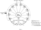
FIG. 6 is a schematic diagram illustrating tube flows of the USC tower-type solar power system of the present disclosure; -
FIG. 7 is a schematic diagram illustrating flow directions of the preheating tube row of the present disclosure; and -
FIG. 8 is a schematic diagram illustrating the heat-carrying compensation arrangement of the mixing tube row of the present disclosure. - Reference numerals: 1: grille-hot-plate current-sharing screen; 1.1: heat-absorbing plate; 1.2: metal fiber felt; 1.3: metal wire mesh; 1.4: grille; 1.4.1: V-shaped grid; 1.5: sealing plate; 1.6: intermediate partition plate; 2: tube row; 2.1: preheating pipeline; 2.2: preheating-tube main pipeline branch tube; 2.3: overheating-tube main pipeline branch tube; 2.4: overheating pipeline; 3: graphite filling layer; and 4: inner tubular wall.
- The present disclosure is described in further detail below with reference to the accompanying drawings.
- As shown in
FIG. 1 andFIG. 4 , an USC tower-type solar heat absorber is provided, including: grille-hot-plate current-sharing screen 1,tube row 2, andgraphite filling layer 3. The grille-hot-plate current-sharing screen 1 is assembled by a plurality of grille hot plates, and concentrated sunlight is irradiated on a grille hot plate of the grille-hot-plate current-sharingscreen 1. Based on the principle of efficient heat transfer of heat tubes, the grille hot plate has characteristics such as rapid response, excellent heat transfer performance, superior isothermal performance, and high stability, and in combination with an indirect heat transfer manner, the grille hot plate can effectively solve the problems such as thermal stress and thermal fatigue caused by a huge temperature difference due to direct heat transfer. - As shown in
FIG. 1 and FIG. 2 , during a working process, high heat-flow density solar energy gathered by a heliostat is irradiated on heat-absorbing plate 1.1 of the grille hot plate, and because an outer surface of the heat-absorbing plate 1.1 is coated with a high temperature-resistant light-absorbing coating, heat is transferred to an inside of the grille hot plate through heat absorption and heating of the heat-absorbing plate 1.1; and liquid metal sodium (or liquid metal potassium or lithium or a related alloy) absorbs the heat and evaporates, then is condensed on a condensation surface of intermediate partition plate 1.6 to release a large amount of heat, and then returns through an inclination direction of grille 1.4 to metal fiber felt 1.2 and metal wire mesh 1.3 to produce a stable two-phase flow, such as to allow efficient phase-transition heat transfer. In addition, a capillary effect of the metal fiber felt 1.2 can make condensed and returned liquid metal sodium evenly distributed on an inner wall surface (namely, an evaporation surface) of the heat-absorbing plate 1.1, homogenize a heat-flow density on a surface of the grille-hot-plate current-sharing screen 1, and greatly reduce a temperature difference of a surface of the grille-hot-plate current-sharing screen 1, such that a heat-absorbing surface of the grille hot plate has excellent isothermal performance to reduce a damage of a thermal stress caused by uneven heating to the heat absorber. The heat released by condensation is continuously transferred to thegraphite filling layer 3 through the intermediate partition plate 1.6, then transferred to thetube row 2 embedded in thegraphite filling layer 3, and then taken away by a heat-transfer medium. - As shown in
FIG. 2 , the grille hot plate includes the heat-absorbing plate 1.1, the metal fiber felt 1.2, the metal wire mesh 1.3, the grille 1.4, sealing plate 1.5, the intermediate partition plate 1.6, and the liquid metal sodium, where the metal fiber felt 1.2 is tightly attached to an inner surface of the heat-absorbing plate 1.1, the metal wire mesh 1.3 covers the metal fiber felt 1.2, and the metal wire mesh 1.3 and the metal fiber felt 1.2 are spot-welded on the inner surface of the heat-absorbing plate 1.1 through a nickel sheet; and the grille 1.4 is directly connected to a condensation surface of the intermediate partition plate 1.6 through 3D printing, and extends obliquely to the metal wire mesh 1.3. A phase transition process of liquid metal sodium can quickly transfer a large amount of heat, and liquid metal sodium has characteristics such as wide operating temperature range, low viscosity, low melting point, high boiling point, high heat transfer efficiency, and low saturated steam pressure. The phase-transition working medium can also be replaced by potassium, lithium, or a related alloy, and is filled in a volume 40% of a volume of the grille hot plate under working conditions. In addition, an inside of the grille hot plate is in a vacuum state, which can avoid problems such as oxidation of materials inside the grille hot plate. - As shown in
FIG. 2 , materials of the heat-absorbing plate 1.1, the metal fiber felt 1.2, the metal wire mesh 1.3, the grille 1.4, the sealing plate 1.5, and the intermediate partition plate 1.6 all are materials such as stainless steel or high-temperature nickel-based alloys compatible with metal sodium. A liquid metal has a high boiling temperature and excellent heat transfer performance, and is allowed to operate at a high heat-flow intensity, but has compatibility requirements for a packaging material. - As shown in
FIG. 2 andFIG. 3 , the grille 1.4 includes a plurality of V-shaped grids 1.4.1 with a predetermined inclination angle; and a longitudinal section of each V-shaped grid 1.4.1 is V-shaped, and symmetrical rectangular sheet structures are provided at two sides, such that the V-shaped grid is like an open book page as a whole. The V-shaped grid 1.4.1 has a predetermined inclination angle θ (10° to 20°) relative to a horizontal plane, and a gap is formed among the V-shaped grids 1.4.1, such that the V-shaped grids communicate with each other, and a vaporized phase-transition working medium can flow quickly and freely inside the grille hot plate. The grille hot plate is enclosed and fixed by the sealing plate 1.5. The inclination angle is designed to make condensed liquid sodium quickly return to the liquid-absorbing core (including the metal fiber felt 1.2 and the metal wire mesh 1.3) under a gravity action, and the V-shaped grids 1.4.1 are designed to make a sodium steam in each V-shaped grid 1.4.1 undergo countless micro-heat tube cycles and make the lateral flow resistance of a V-shaped flow channel small. The unitization of large-space evaporation and condensation cycles increases a condensation heat transfer area, and shortens a condensation and returning pathway of liquid sodium, such that condensed and returned liquid sodium can be evenly distributed on the liquid-absorbing core, which significantly improves the isothermal performance of the heat-absorbing plate 1.1. - As shown in
FIG. 4 andFIG. 5 , the grille-hot-plate current-sharing screen 1 includes a plurality of grille hot plates; each grille-hot-plate current-sharing screen 1 corresponds to onetube row 2; and graphite is filled between the grille-hot-plate current-sharing screen 1 and thetube row 2 and between the grille-hot-plate current-sharing screen 1 and the innertubular wall 4. A high thermal conductivity coefficient of graphite can enhance a heat exchange effect of a heat-transfer medium in preheating pipeline 2.1 and overheating pipeline 2.4; and the excellent adhesion of graphite to a metal surface can effectively prevent a tube from being oxidized. - As shown in
FIG. 6 ,FIG. 7 , andFIG. 8 , thetube row 2 includes preheating pipeline 2.1, overheating pipeline 2.4, a main pipeline, and a heat-transfer medium. According to different functions, thetube row 2 includes a preheating tube row and a mixing tube row, the preheating tube row includes a plurality of preheating pipelines 2.1, and the mixing tube row includes a plurality of preheating pipelines 2.1 and a plurality of overheating pipeline 2.4. All preheating pipelines are connected in series. Water flows from a previous tube row to the next tube row, and after water passes through a plurality of tube rows, saturated steams in a supercritical state are produced and gathered in the main pipeline, and then introduced into overheating pipeline 2.4 of each mixing tube row to be superheated. Because a superheated steam has a weak heat-carrying capacity, the overheating pipeline 2.4 and the preheating pipelines 2.1 are arranged in a heat-carrying compensation manner, such that each of left and right sides of each overheating pipeline 2.4 is provided with a preheating pipeline 2.1 for compensation. The heat-transfer medium is water under an USC pressure, and because water has a large specific heat capacity and a strong heat-transfer capacity, a high-pressure water pump is used to increase a pressure of water to the USC pressure (27 MPa or more). When water passes through the plurality of tube rows to produce saturated steams, the heat-carrying capacity decreases, and a temperature of the overheating pipeline 2.4 increases sharply, which easily causes burst and other dangers to the overheating pipeline 2.4. The heat-carrying compensation arrangement can effectively make up for this shortcoming. The overall tightness and materials of tubes of the system need to meet very strict standards, and thetube row 2 is made of a high temperature-resistant pressure-bearing material such as T22 steel, T23 steel, or 12Cr1MoVG steel. - In a specific embodiment shown in an accompanying drawing, each preheating tube row includes three preheating pipelines 2.1, and each mixing tube row includes three preheating pipelines 2.1 and three overheating pipeline 2.4; and a specific number of tubes can be increased or decreased according to actual needs. A pressure of water is increased by a high-pressure water pump to an USC pressure, and water under the USC pressure first enters preheating pipelines 2.1 of an mth mixing tube row and then flows to preheating pipelines 2.1 in a corresponding preheating tube row; after passing through a total of
n tube rows 2, the water under the USC pressure is converted into saturated steams, and the saturated steams are gathered in the main pipeline; and the gathered saturated steam is introduced through the main pipeline into overheating pipeline connected in parallel and superheated to produce USC superheated steams, and the USC superheated steams are gathered and output to drive the power generation of a steam turbine. - As shown in
FIG. 7 , in each preheating tube row, three preheating pipelines 2.1 are arranged between upper and lower two preheating-tube main pipeline branch tubes 2.2, where the preheating-tube main pipeline branch tube 2.2 at one side is configured to receive an inflow from a previous tube row, and the preheating-tube main pipeline branch tube 2.2 at the other side is configured to allow an outflow into the next tube row; and the preheating tube rows are connected in series. - As shown in
FIG. 8 , in each mixing tube row, three preheating pipelines 2.1 are arranged between upper and lower two preheating-tube main pipeline branch tubes 2.2, where one preheating-tube main pipeline branch tube 2.2 at one side serves as a water inlet, and the other preheating-tube main pipeline branch tube 2.2 at the other side serves as a water outlet; and three overheating pipeline 2.4 are arranged between upper and lower two overheating-tube main pipeline branch tubes 2.3, where one overheating-tube main pipeline branch tube 2.3 at one side serves as a steam inlet such that a steam flows in through the main pipeline, and the other overheating-tube main pipeline branch tube 2.3 at the other side serves as a superheated steam outlet. In the mixing tube row, the preheating pipelines 2.1 and the overheating pipeline 2.4 are arranged in a heat-carrying compensation manner, and the preheating pipelines 2.1 and the overheating pipeline 2.4 are arranged at a predetermined interval. When a produced saturated steam enters the overheating pipeline 2.4 and is superheated, a volume of the saturated steam expands sharply, and a temperature of the saturated steam increases rapidly. In order to prevent burst of the overheating pipeline 2.4, the heat-carrying compensation arrangement is adopted, and a diameter of the overheating pipeline 2.4 is much larger than a diameter of the preheating pipeline 2.1. - As shown in
FIG. 5 ,FIG. 7 , andFIG. 8 , a graphite powder or a graphite mixture is filled in a gap between the preheating pipeline 2.1 and the overheating pipeline 2.4, and graphite and a high-temperature thermally-conductive adhesive are mixed and filled in gaps among each grille-hot-plate current-sharing screen 1, eachtube row 2, and the innertubular wall 4 for packaging. Graphite has a high thermal conductivity coefficient, which can stably enhance a heat exchange effect of a heat-transfer medium in the plurality of preheating pipelines 2.1 and overheating pipeline 2.4; and graphite has excellent adhesion to a metal surface, which can effectively prevent the plurality of preheating pipelines 2.1 and overheating pipeline 2.4 from being oxidized. - As shown in
FIG. 1 , the grille hot plates in each grille-hot-plate current-sharing screen 1 are separate heat-absorbing elements, can work separately without affecting each other, and can be disassembled and replaced separately when damaged and repaired; and the grille-hot-plate current-sharingscreens 1 also do not affect each other, which allows excellent safety and stability performance during working and greatly reduces a maintenance cost. - In summary, in the present disclosure, based on the principle of efficient heat transfer of heat tubes, an indirect heat transfer manner is adopted, and a phase-transition working medium undergoes micro-heat tube cycles in a grille of a grille hot plate, such that a condensed and returned phase-transition working medium is evenly distributed on the evaporation surface of the heat-absorbing plate, and a heat-absorbing surface of a grille hot plate has excellent isothermal performance and can withstand a thermal load under a high heat-flow density, which can prevent the problems such as thermal fatigue caused by local overheating and prolong a service life of the heat absorber. Like other types of solar heat absorbers, the heat absorber of the present disclosure adopts the principle of phase-transition heat transfer, except that high-temperature liquid metal sodium, potassium, or lithium or a related alloy is adopted as a phase-transition working medium inside the heat absorber. Heat is transferred through a phase transition of liquid metal sodium to the graphite filling layer, then further transferred to the tube rows embedded in the graphite, and then taken away by a heat-transfer medium (water) flowing through the tube rows, which avoids direct sunlight irradiation to provide heat and further avoids uneven heating. In the present disclosure, it is designed to adopt a gap filling method, where graphite is filled in gaps among tube rows. Graphite has a high thermal conductivity coefficient, which can further enhance a heat exchange effect of a heat-transfer medium in a preheating pipeline and an overheating pipeline; and graphite has excellent adhesion to a metal surface, which can effectively prevent a tube from being oxidized. The heat absorber structure can heat water to an USC state, which greatly improves the operating parameters and power generation efficiency.
Claims (9)
- An ultra-supercritical (USC) tower-type solar heat absorber, characterized by comprising: a plurality of grille-hot-plate current-sharing screens (1), a plurality of tube rows (2), and a graphite filling layer (3), wherein each of the plurality of grille-hot-plate current-sharing screens (1) is assembled by a plurality of grille hot plates independent of each other; and when sunlight is reflected and concentrated on the plurality of grille-hot-plate current-sharing screens (1), heat transfer is allowed by a phase transition of a phase-transition working medium inside the grille hot plates, and heat is transferred through the graphite filling layer (3) to the plurality of tube rows (2) embedded in the graphite filling layer (3) and taken away by a heat-transfer medium flowing through the plurality of tube rows (2);
each of the plurality of grille hot plates comprises a heat-absorbing plate (1.1), a metal fiber felt (1.2), a metal wire mesh (1.3), a grille (1.4), a sealing plate (1.5), and an intermediate partition plate (1.6); wherein the metal fiber felt (1.2), the metal wire mesh (1.3), the grille (1.4), and the intermediate partition plate (1.6) are sequentially arranged on an evaporation surface of the heat-absorbing plate (1.1); the metal fiber felt (1.2) is tightly attached to the evaporation surface of the heat-absorbing plate (1.1), and the metal wire mesh (1.3) covers a surface of the metal fiber felt (1.2); the metal fiber felt (1.2) and the metal wire mesh (1.3) together constitute a liquid-absorbing core; the grille (1.4) is directly connected to a condensation surface of the intermediate partition plate (1.6), and extends obliquely to the metal wire mesh (1.3); and the grille hot plate is enclosed by the sealing plate (1.5), filled with the phase-transition working medium, and pumped to a vacuum state. - The USC tower-type solar heat absorber according to claim 1, characterized in that the metal wire mesh (1.3) and the metal fiber felt (1.2) are spot-welded on the evaporation surface of the heat-absorbing plate (1.1), and the grille (1.4) is directly connected to the intermediate partition plate (1.6) through three-dimensional (3D) printing.
- The USC tower-type solar heat absorber according to claim 1, characterized in that the grille (1.4) comprises a plurality of V-shaped grids (1.4.1) evenly distributed on the intermediate partition plate (1.6), and a longitudinal section of each of the plurality of V-shaped grids (1.4.1) is V-shaped; each of the plurality of V-shaped grids (1.4.1) has a predetermined inclination angle relative to a horizontal plane, such that the phase-transition working medium is allowed to be condensed and returned to the liquid-absorbing core through the grille (1.4); and a gap is formed among the plurality of V-shaped grids (1.4.1).
- The USC tower-type solar heat absorber according to claim 1, characterized in that the phase-transition working medium is liquid metal sodium, liquid metal potassium, liquid metal lithium, or a liquid metal alloy.
- The USC tower-type solar heat absorber according to claim 1, characterized in that each of the plurality of grille-hot-plate current-sharing screens (1) corresponds to one tube row (2); and heat is transferred through the graphite filling layer (3) to each tube row (2) embedded in the graphite filling layer (3) to produce an USC superheated steam.
- The USC tower-type solar heat absorber according to claim 5, characterized in that each of the plurality of tube rows (2) comprises a preheating tube row and a mixing tube row; the preheating tube row comprises a plurality of preheating pipelines (2.1), and the mixing tube row comprises a plurality of preheating pipelines (2.1) and a plurality of overheating pipeline (2.4) that are arranged at a predetermined interval; and water under an USC pressure passes first through preheating pipelines (2.1) of the plurality of mixing tube rows sequentially and then through preheating pipelines (2.1) of the plurality of preheating tube rows sequentially to produce saturated steams, the saturated steams are gathered in a main pipeline and then introduced through the main pipeline into overheating pipelines (2.4) of the plurality of mixing tube rows to be superheated, and USC superheated steams generated by the overheating pipelines (2.4) of the plurality of mixing tube rows are gathered and output.
- The USC tower-type solar heat absorber according to claim 6, characterized in that in the mixing tube row, the plurality of preheating pipelines (2.1) and the plurality of overheating pipeline (2.4) are arranged in a heat-carrying compensation manner, such that each of left and right sides of each overheating pipeline (2.4) is provided with a preheating pipeline (2.1) for compensation, wherein a diameter of the overheating pipeline (2.4) is greater than a diameter of the preheating pipeline (2.1).
- The USC tower-type solar heat absorber according to claim 1, characterized in that the plurality of tube rows (2) are made of T22 steel, T23 steel, or 12Cr1MoVG steel.
- The USC tower-type solar heat absorber according to claim 1, characterized in that the graphite filling layer (3) is filled between the tube rows (2) and the grille hot plates and between the tube rows (2) and an inner tubular wall (4) of the USC tower-type solar heat absorber, and the graphite filling layer (3) is made of a graphite powder or a graphite mixture.
Applications Claiming Priority (2)
| Application Number | Priority Date | Filing Date | Title |
|---|---|---|---|
| CN202210035771.9A CN114353345B (en) | 2022-01-13 | 2022-01-13 | An ultra-supercritical tower solar heat absorber |
| PCT/CN2022/078584 WO2023133979A1 (en) | 2022-01-13 | 2022-03-01 | Ultra-supercritical tower-type solar heat absorber |
Publications (3)
| Publication Number | Publication Date |
|---|---|
| EP4306870A1 EP4306870A1 (en) | 2024-01-17 |
| EP4306870A4 EP4306870A4 (en) | 2024-06-12 |
| EP4306870B1 true EP4306870B1 (en) | 2025-04-02 |
Family
ID=81110144
Family Applications (1)
| Application Number | Title | Priority Date | Filing Date |
|---|---|---|---|
| EP22919624.1A Active EP4306870B1 (en) | 2022-01-13 | 2022-03-01 | Ultra-supercritical tower-type solar heat absorber |
Country Status (5)
| Country | Link |
|---|---|
| US (1) | US11879667B1 (en) |
| EP (1) | EP4306870B1 (en) |
| CN (1) | CN114353345B (en) |
| ES (1) | ES3022542T3 (en) |
| WO (1) | WO2023133979A1 (en) |
Families Citing this family (5)
| Publication number | Priority date | Publication date | Assignee | Title |
|---|---|---|---|---|
| CN115183476A (en) * | 2022-07-26 | 2022-10-14 | 南京工业大学 | Ultra-supercritical solar tower type water working medium heat absorber |
| CN115388564B (en) * | 2022-08-12 | 2026-04-21 | 南京工业大学 | A tower-type solar supercritical air receiver |
| CN116294252B (en) * | 2023-03-28 | 2026-01-06 | 浙江可胜技术股份有限公司 | A heat absorber |
| CN116428754B (en) * | 2023-05-05 | 2026-04-28 | 南京工业大学 | A tower-type solar vortex absorber |
| CN119412991A (en) * | 2024-11-29 | 2025-02-11 | 中国华电科工集团有限公司 | Energy storage system and operation method thereof |
Family Cites Families (23)
| Publication number | Priority date | Publication date | Assignee | Title |
|---|---|---|---|---|
| US4289114A (en) * | 1978-09-12 | 1981-09-15 | The Babcock & Wilcox Company | Control system for a solar steam generator |
| US4296730A (en) * | 1978-09-12 | 1981-10-27 | The Babcock & Wilcox Company | Control system for a solar steam generator |
| US4485803A (en) * | 1982-10-14 | 1984-12-04 | The Babcock & Wilcox Company | Solar receiver with interspersed panels |
| TWI285251B (en) * | 2005-09-15 | 2007-08-11 | Univ Tsinghua | Flat-plate heat pipe containing channels |
| KR100804183B1 (en) * | 2007-02-22 | 2008-02-18 | 인하대학교 산학협력단 | Receiver structure of tower solar generator |
| US20090260785A1 (en) * | 2008-04-17 | 2009-10-22 | Wang Cheng-Tu | Heat plate with capillary supporting structure and manufacturing method thereof |
| TWI459889B (en) * | 2008-09-18 | 2014-11-01 | Pegatron Corp | Vapor chamber |
| US8517008B2 (en) * | 2009-02-12 | 2013-08-27 | Babcock Power Services, Inc. | Modular solar receiver panels and solar boilers with modular receiver panels |
| US20100314081A1 (en) * | 2009-06-12 | 2010-12-16 | Reis Bradley E | High Temperature Graphite Heat Exchanger |
| US9488386B2 (en) * | 2009-09-18 | 2016-11-08 | Massachusetts Institute Of Technology | Concentrated solar power system receiver |
| CA2750315A1 (en) * | 2011-08-19 | 2013-02-19 | Huazi Lin | Non-orthogonal solar heat collector and solar energy cogeneration |
| CN102445008B (en) * | 2011-12-08 | 2013-02-20 | 南京工业大学 | Tower type solar water/steam composite plate-fin hot plate type heat absorber |
| WO2013181712A1 (en) * | 2012-06-08 | 2013-12-12 | Graphite Energy N.V | Solar energy receiver |
| CN102927697B (en) * | 2012-11-05 | 2015-08-05 | 南京工业大学 | High-pressure-bearing tower type solar water/molten salt composite flat-tube type hot plate heat absorber |
| CN204128216U (en) * | 2014-10-11 | 2015-01-28 | 东方电气集团东方锅炉股份有限公司 | A kind of tower type solar heat dump |
| CN105634404A (en) * | 2014-10-27 | 2016-06-01 | 山东天巨建设工程有限公司 | One-chip solar photovoltaic cell panel temperature control integrated piece |
| CN105157243A (en) * | 2015-09-10 | 2015-12-16 | 北京首航艾启威节能技术股份有限公司 | Novel heat absorber of tower-type photo-thermal power station |
| CN106052159B (en) * | 2016-05-27 | 2017-12-26 | 浙江大学 | A kind of gas-particle two-phase heat exchange heat accumulation type solar thermal collection system and method |
| US10066876B2 (en) * | 2016-09-09 | 2018-09-04 | Toyota Motor Engineering & Manufacturing North America, Inc. | Vapor chamber heat flux rectifier and thermal switch |
| CN108489122B (en) * | 2018-05-23 | 2023-06-02 | 东方电气集团东方锅炉股份有限公司 | Tower type solar molten salt heat absorber heat preservation structure |
| CN209569914U (en) * | 2018-10-29 | 2019-11-01 | 浙江大学 | Heat dump |
| CN213741687U (en) * | 2020-09-22 | 2021-07-20 | 裘斌 | Paper surface composite heat insulation board |
| CN112856832B (en) * | 2021-01-13 | 2022-04-08 | 南京工业大学 | Novel flat plate heat sink for solar tower power generation and system using the same |
-
2022
- 2022-01-13 CN CN202210035771.9A patent/CN114353345B/en active Active
- 2022-03-01 US US18/272,353 patent/US11879667B1/en active Active
- 2022-03-01 WO PCT/CN2022/078584 patent/WO2023133979A1/en not_active Ceased
- 2022-03-01 EP EP22919624.1A patent/EP4306870B1/en active Active
- 2022-03-01 ES ES22919624T patent/ES3022542T3/en active Active
Also Published As
| Publication number | Publication date |
|---|---|
| US20240035709A1 (en) | 2024-02-01 |
| ES3022542T3 (en) | 2025-05-28 |
| WO2023133979A1 (en) | 2023-07-20 |
| EP4306870A1 (en) | 2024-01-17 |
| EP4306870A4 (en) | 2024-06-12 |
| CN114353345A (en) | 2022-04-15 |
| US11879667B1 (en) | 2024-01-23 |
| CN114353345B (en) | 2023-06-02 |
Similar Documents
| Publication | Publication Date | Title |
|---|---|---|
| US11879667B1 (en) | Ultra-supercritical tower-type solar heat absorber | |
| US12578122B2 (en) | Flat heat absorber for solar tower power generation and system using same | |
| JP6280275B2 (en) | Solar thermal power generation method and apparatus by gas endotherm based on characteristic absorption spectrum | |
| CN102852742B (en) | Tower type solar thermal power generation system for heat absorber of vacuum heat absorption pipes | |
| CN101033892B (en) | High-temperature heat absorber for a solar tower thermal power station | |
| CN102635462B (en) | Heat storage temperature control device of solar disc-type Sterling engine | |
| WO2012022273A1 (en) | Solar power ammonia thermoelectric conversion system | |
| WO2024021296A1 (en) | Ultra-supercritical solar tower-type water working medium heat absorber | |
| CN217876502U (en) | Ultra-supercritical solar tower type water working medium heat absorber | |
| CN1776322A (en) | Binary medium solar high temperature heat absorption/storage device | |
| CN101275785A (en) | High temperature heat pipe central receiver for tower solar thermal power generation | |
| CN107084102A (en) | It is a kind of using carbon dioxide as heat accumulation and do work working medium groove type solar solar-thermal generating system | |
| CN102135334A (en) | Silica glass tube bundle type air heat absorber for solar heat generating station | |
| CN102445008A (en) | Tower solar water/steam composite plate-fin heat absorber | |
| CN115388564A (en) | Tower-type solar supercritical air heat absorber | |
| CN108301927B (en) | Solar high temperature heat collection and storage gas turbine power generation device | |
| CN116428754B (en) | A tower-type solar vortex absorber | |
| CN111829197A (en) | A counter-flow high-temperature particle heat absorber for tower solar power generation power generation | |
| CN220366563U (en) | A tower type solar cyclone heat absorber | |
| CN109058767B (en) | Nuclear reactor steam storage and heating system | |
| CN102927697B (en) | High-pressure-bearing tower type solar water/molten salt composite flat-tube type hot plate heat absorber | |
| CN2851982Y (en) | Double-medium solar high-temperature heat absorbing and storing device | |
| CN201259336Y (en) | Novel flat-plate solar heat collector | |
| CN103017367B (en) | Tower type solar composite plate-fin hot plate type heat absorber with novel supporting structure | |
| CN115982880A (en) | A high-low temperature dual-mass heat absorber and its design method for a tower-type photothermal power station |
Legal Events
| Date | Code | Title | Description |
|---|---|---|---|
| STAA | Information on the status of an ep patent application or granted ep patent |
Free format text: STATUS: THE INTERNATIONAL PUBLICATION HAS BEEN MADE |
|
| PUAI | Public reference made under article 153(3) epc to a published international application that has entered the european phase |
Free format text: ORIGINAL CODE: 0009012 |
|
| STAA | Information on the status of an ep patent application or granted ep patent |
Free format text: STATUS: REQUEST FOR EXAMINATION WAS MADE |
|
| 17P | Request for examination filed |
Effective date: 20231013 |
|
| AK | Designated contracting states |
Kind code of ref document: A1 Designated state(s): AL AT BE BG CH CY CZ DE DK EE ES FI FR GB GR HR HU IE IS IT LI LT LU LV MC MK MT NL NO PL PT RO RS SE SI SK SM TR |
|
| A4 | Supplementary search report drawn up and despatched |
Effective date: 20240510 |
|
| RIC1 | Information provided on ipc code assigned before grant |
Ipc: F24S 70/60 20180101ALI20240503BHEP Ipc: F24S 70/10 20180101ALI20240503BHEP Ipc: F24S 60/10 20180101ALI20240503BHEP Ipc: F24S 10/95 20180101AFI20240503BHEP |
|
| GRAP | Despatch of communication of intention to grant a patent |
Free format text: ORIGINAL CODE: EPIDOSNIGR1 |
|
| STAA | Information on the status of an ep patent application or granted ep patent |
Free format text: STATUS: GRANT OF PATENT IS INTENDED |
|
| DAV | Request for validation of the european patent (deleted) | ||
| DAX | Request for extension of the european patent (deleted) | ||
| INTG | Intention to grant announced |
Effective date: 20241104 |
|
| GRAS | Grant fee paid |
Free format text: ORIGINAL CODE: EPIDOSNIGR3 |
|
| GRAA | (expected) grant |
Free format text: ORIGINAL CODE: 0009210 |
|
| STAA | Information on the status of an ep patent application or granted ep patent |
Free format text: STATUS: THE PATENT HAS BEEN GRANTED |
|
| AK | Designated contracting states |
Kind code of ref document: B1 Designated state(s): AL AT BE BG CH CY CZ DE DK EE ES FI FR GB GR HR HU IE IS IT LI LT LU LV MC MK MT NL NO PL PT RO RS SE SI SK SM TR |
|
| REG | Reference to a national code |
Ref country code: GB Ref legal event code: FG4D |
|
| REG | Reference to a national code |
Ref country code: CH Ref legal event code: EP |
|
| P01 | Opt-out of the competence of the unified patent court (upc) registered |
Free format text: CASE NUMBER: APP_11681/2025 Effective date: 20250310 |
|
| REG | Reference to a national code |
Ref country code: IE Ref legal event code: FG4D |
|
| REG | Reference to a national code |
Ref country code: DE Ref legal event code: R096 Ref document number: 602022012723 Country of ref document: DE |
|
| REG | Reference to a national code |
Ref country code: ES Ref legal event code: FG2A Ref document number: 3022542 Country of ref document: ES Kind code of ref document: T3 Effective date: 20250528 |
|
| REG | Reference to a national code |
Ref country code: NL Ref legal event code: MP Effective date: 20250402 |
|
| PG25 | Lapsed in a contracting state [announced via postgrant information from national office to epo] |
Ref country code: NL Free format text: LAPSE BECAUSE OF FAILURE TO SUBMIT A TRANSLATION OF THE DESCRIPTION OR TO PAY THE FEE WITHIN THE PRESCRIBED TIME-LIMIT Effective date: 20250402 |
|
| REG | Reference to a national code |
Ref country code: AT Ref legal event code: MK05 Ref document number: 1781613 Country of ref document: AT Kind code of ref document: T Effective date: 20250402 |
|
| PG25 | Lapsed in a contracting state [announced via postgrant information from national office to epo] |
Ref country code: PT Free format text: LAPSE BECAUSE OF FAILURE TO SUBMIT A TRANSLATION OF THE DESCRIPTION OR TO PAY THE FEE WITHIN THE PRESCRIBED TIME-LIMIT Effective date: 20250804 Ref country code: FI Free format text: LAPSE BECAUSE OF FAILURE TO SUBMIT A TRANSLATION OF THE DESCRIPTION OR TO PAY THE FEE WITHIN THE PRESCRIBED TIME-LIMIT Effective date: 20250402 |
|
| REG | Reference to a national code |
Ref country code: LT Ref legal event code: MG9D |
|
| PG25 | Lapsed in a contracting state [announced via postgrant information from national office to epo] |
Ref country code: GR Free format text: LAPSE BECAUSE OF FAILURE TO SUBMIT A TRANSLATION OF THE DESCRIPTION OR TO PAY THE FEE WITHIN THE PRESCRIBED TIME-LIMIT Effective date: 20250703 Ref country code: NO Free format text: LAPSE BECAUSE OF FAILURE TO SUBMIT A TRANSLATION OF THE DESCRIPTION OR TO PAY THE FEE WITHIN THE PRESCRIBED TIME-LIMIT Effective date: 20250702 |
|
| PG25 | Lapsed in a contracting state [announced via postgrant information from national office to epo] |
Ref country code: PL Free format text: LAPSE BECAUSE OF FAILURE TO SUBMIT A TRANSLATION OF THE DESCRIPTION OR TO PAY THE FEE WITHIN THE PRESCRIBED TIME-LIMIT Effective date: 20250402 |
|
| PG25 | Lapsed in a contracting state [announced via postgrant information from national office to epo] |
Ref country code: BG Free format text: LAPSE BECAUSE OF FAILURE TO SUBMIT A TRANSLATION OF THE DESCRIPTION OR TO PAY THE FEE WITHIN THE PRESCRIBED TIME-LIMIT Effective date: 20250402 |
|
| PG25 | Lapsed in a contracting state [announced via postgrant information from national office to epo] |
Ref country code: HR Free format text: LAPSE BECAUSE OF FAILURE TO SUBMIT A TRANSLATION OF THE DESCRIPTION OR TO PAY THE FEE WITHIN THE PRESCRIBED TIME-LIMIT Effective date: 20250402 |
|
| PG25 | Lapsed in a contracting state [announced via postgrant information from national office to epo] |
Ref country code: AT Free format text: LAPSE BECAUSE OF FAILURE TO SUBMIT A TRANSLATION OF THE DESCRIPTION OR TO PAY THE FEE WITHIN THE PRESCRIBED TIME-LIMIT Effective date: 20250402 |
|
| PG25 | Lapsed in a contracting state [announced via postgrant information from national office to epo] |
Ref country code: RS Free format text: LAPSE BECAUSE OF FAILURE TO SUBMIT A TRANSLATION OF THE DESCRIPTION OR TO PAY THE FEE WITHIN THE PRESCRIBED TIME-LIMIT Effective date: 20250702 |
|
| PG25 | Lapsed in a contracting state [announced via postgrant information from national office to epo] |
Ref country code: IS Free format text: LAPSE BECAUSE OF FAILURE TO SUBMIT A TRANSLATION OF THE DESCRIPTION OR TO PAY THE FEE WITHIN THE PRESCRIBED TIME-LIMIT Effective date: 20250802 |
|
| PG25 | Lapsed in a contracting state [announced via postgrant information from national office to epo] |
Ref country code: LV Free format text: LAPSE BECAUSE OF FAILURE TO SUBMIT A TRANSLATION OF THE DESCRIPTION OR TO PAY THE FEE WITHIN THE PRESCRIBED TIME-LIMIT Effective date: 20250402 |
|
| REG | Reference to a national code |
Ref country code: DE Ref legal event code: R097 Ref document number: 602022012723 Country of ref document: DE |
|
| PG25 | Lapsed in a contracting state [announced via postgrant information from national office to epo] |
Ref country code: SM Free format text: LAPSE BECAUSE OF FAILURE TO SUBMIT A TRANSLATION OF THE DESCRIPTION OR TO PAY THE FEE WITHIN THE PRESCRIBED TIME-LIMIT Effective date: 20250402 Ref country code: DK Free format text: LAPSE BECAUSE OF FAILURE TO SUBMIT A TRANSLATION OF THE DESCRIPTION OR TO PAY THE FEE WITHIN THE PRESCRIBED TIME-LIMIT Effective date: 20250402 |
|
| PG25 | Lapsed in a contracting state [announced via postgrant information from national office to epo] |
Ref country code: CZ Free format text: LAPSE BECAUSE OF FAILURE TO SUBMIT A TRANSLATION OF THE DESCRIPTION OR TO PAY THE FEE WITHIN THE PRESCRIBED TIME-LIMIT Effective date: 20250402 |
|
| PG25 | Lapsed in a contracting state [announced via postgrant information from national office to epo] |
Ref country code: EE Free format text: LAPSE BECAUSE OF FAILURE TO SUBMIT A TRANSLATION OF THE DESCRIPTION OR TO PAY THE FEE WITHIN THE PRESCRIBED TIME-LIMIT Effective date: 20250402 |
|
| PG25 | Lapsed in a contracting state [announced via postgrant information from national office to epo] |
Ref country code: SK Free format text: LAPSE BECAUSE OF FAILURE TO SUBMIT A TRANSLATION OF THE DESCRIPTION OR TO PAY THE FEE WITHIN THE PRESCRIBED TIME-LIMIT Effective date: 20250402 |
|
| PG25 | Lapsed in a contracting state [announced via postgrant information from national office to epo] |
Ref country code: IT Free format text: LAPSE BECAUSE OF FAILURE TO SUBMIT A TRANSLATION OF THE DESCRIPTION OR TO PAY THE FEE WITHIN THE PRESCRIBED TIME-LIMIT Effective date: 20250402 |
|
| PLBE | No opposition filed within time limit |
Free format text: ORIGINAL CODE: 0009261 |
|
| STAA | Information on the status of an ep patent application or granted ep patent |
Free format text: STATUS: NO OPPOSITION FILED WITHIN TIME LIMIT |
|
| REG | Reference to a national code |
Ref country code: CH Ref legal event code: L10 Free format text: ST27 STATUS EVENT CODE: U-0-0-L10-L00 (AS PROVIDED BY THE NATIONAL OFFICE) Effective date: 20260211 |
|
| 26N | No opposition filed |
Effective date: 20260105 |
|
| PGFP | Annual fee paid to national office [announced via postgrant information from national office to epo] |
Ref country code: DE Payment date: 20260317 Year of fee payment: 5 |
|
| PGFP | Annual fee paid to national office [announced via postgrant information from national office to epo] |
Ref country code: BE Payment date: 20260317 Year of fee payment: 5 |
|
| PG25 | Lapsed in a contracting state [announced via postgrant information from national office to epo] |
Ref country code: LT Free format text: LAPSE BECAUSE OF FAILURE TO SUBMIT A TRANSLATION OF THE DESCRIPTION OR TO PAY THE FEE WITHIN THE PRESCRIBED TIME-LIMIT Effective date: 20250402 |
|
| PGFP | Annual fee paid to national office [announced via postgrant information from national office to epo] |
Ref country code: ES Payment date: 20260406 Year of fee payment: 5 |
|
| PG25 | Lapsed in a contracting state [announced via postgrant information from national office to epo] |
Ref country code: SE Free format text: LAPSE BECAUSE OF FAILURE TO SUBMIT A TRANSLATION OF THE DESCRIPTION OR TO PAY THE FEE WITHIN THE PRESCRIBED TIME-LIMIT Effective date: 20250402 |