EP4306848A1 - Vehicle lamp - Google Patents
Vehicle lamp Download PDFInfo
- Publication number
- EP4306848A1 EP4306848A1 EP22767229.2A EP22767229A EP4306848A1 EP 4306848 A1 EP4306848 A1 EP 4306848A1 EP 22767229 A EP22767229 A EP 22767229A EP 4306848 A1 EP4306848 A1 EP 4306848A1
- Authority
- EP
- European Patent Office
- Prior art keywords
- light
- plate material
- transmissive areas
- transmissive
- areas
- Prior art date
- Legal status (The legal status is an assumption and is not a legal conclusion. Google has not performed a legal analysis and makes no representation as to the accuracy of the status listed.)
- Pending
Links
Images



Classifications
-
- F—MECHANICAL ENGINEERING; LIGHTING; HEATING; WEAPONS; BLASTING
- F21—LIGHTING
- F21S—NON-PORTABLE LIGHTING DEVICES; SYSTEMS THEREOF; VEHICLE LIGHTING DEVICES SPECIALLY ADAPTED FOR VEHICLE EXTERIORS
- F21S43/00—Signalling devices specially adapted for vehicle exteriors, e.g. brake lamps, direction indicator lights or reversing lights
- F21S43/20—Signalling devices specially adapted for vehicle exteriors, e.g. brake lamps, direction indicator lights or reversing lights characterised by refractors, transparent cover plates, light guides or filters
- F21S43/26—Refractors, transparent cover plates, light guides or filters not provided in groups F21S43/235 - F21S43/255
-
- B—PERFORMING OPERATIONS; TRANSPORTING
- B60—VEHICLES IN GENERAL
- B60Q—ARRANGEMENT OF SIGNALLING OR LIGHTING DEVICES, THE MOUNTING OR SUPPORTING THEREOF OR CIRCUITS THEREFOR, FOR VEHICLES IN GENERAL
- B60Q1/00—Arrangement of optical signalling or lighting devices, the mounting or supporting thereof or circuits therefor
- B60Q1/26—Arrangement of optical signalling or lighting devices, the mounting or supporting thereof or circuits therefor the devices being primarily intended to indicate the vehicle, or parts thereof, or to give signals, to other traffic
- B60Q1/2661—Arrangement of optical signalling or lighting devices, the mounting or supporting thereof or circuits therefor the devices being primarily intended to indicate the vehicle, or parts thereof, or to give signals, to other traffic mounted on parts having other functions
-
- B—PERFORMING OPERATIONS; TRANSPORTING
- B32—LAYERED PRODUCTS
- B32B—LAYERED PRODUCTS, i.e. PRODUCTS BUILT-UP OF STRATA OF FLAT OR NON-FLAT, e.g. CELLULAR OR HONEYCOMB, FORM
- B32B27/00—Layered products comprising a layer of synthetic resin
- B32B27/06—Layered products comprising a layer of synthetic resin as the main or only constituent of a layer, which is next to another layer of the same or of a different material
- B32B27/08—Layered products comprising a layer of synthetic resin as the main or only constituent of a layer, which is next to another layer of the same or of a different material of synthetic resin
-
- B—PERFORMING OPERATIONS; TRANSPORTING
- B60—VEHICLES IN GENERAL
- B60Q—ARRANGEMENT OF SIGNALLING OR LIGHTING DEVICES, THE MOUNTING OR SUPPORTING THEREOF OR CIRCUITS THEREFOR, FOR VEHICLES IN GENERAL
- B60Q1/00—Arrangement of optical signalling or lighting devices, the mounting or supporting thereof or circuits therefor
- B60Q1/0029—Spatial arrangement
- B60Q1/0035—Spatial arrangement relative to the vehicle
-
- F—MECHANICAL ENGINEERING; LIGHTING; HEATING; WEAPONS; BLASTING
- F21—LIGHTING
- F21S—NON-PORTABLE LIGHTING DEVICES; SYSTEMS THEREOF; VEHICLE LIGHTING DEVICES SPECIALLY ADAPTED FOR VEHICLE EXTERIORS
- F21S43/00—Signalling devices specially adapted for vehicle exteriors, e.g. brake lamps, direction indicator lights or reversing lights
- F21S43/10—Signalling devices specially adapted for vehicle exteriors, e.g. brake lamps, direction indicator lights or reversing lights characterised by the light source
- F21S43/13—Signalling devices specially adapted for vehicle exteriors, e.g. brake lamps, direction indicator lights or reversing lights characterised by the light source characterised by the type of light source
- F21S43/14—Light emitting diodes [LED]
-
- F—MECHANICAL ENGINEERING; LIGHTING; HEATING; WEAPONS; BLASTING
- F21—LIGHTING
- F21S—NON-PORTABLE LIGHTING DEVICES; SYSTEMS THEREOF; VEHICLE LIGHTING DEVICES SPECIALLY ADAPTED FOR VEHICLE EXTERIORS
- F21S43/00—Signalling devices specially adapted for vehicle exteriors, e.g. brake lamps, direction indicator lights or reversing lights
- F21S43/20—Signalling devices specially adapted for vehicle exteriors, e.g. brake lamps, direction indicator lights or reversing lights characterised by refractors, transparent cover plates, light guides or filters
- F21S43/2605—Refractors
-
- F—MECHANICAL ENGINEERING; LIGHTING; HEATING; WEAPONS; BLASTING
- F21—LIGHTING
- F21S—NON-PORTABLE LIGHTING DEVICES; SYSTEMS THEREOF; VEHICLE LIGHTING DEVICES SPECIALLY ADAPTED FOR VEHICLE EXTERIORS
- F21S43/00—Signalling devices specially adapted for vehicle exteriors, e.g. brake lamps, direction indicator lights or reversing lights
- F21S43/20—Signalling devices specially adapted for vehicle exteriors, e.g. brake lamps, direction indicator lights or reversing lights characterised by refractors, transparent cover plates, light guides or filters
- F21S43/2605—Refractors
- F21S43/2621—Refractors characterised by the properties of the light beam shaping surface
- F21S43/26241—Refractors characterised by the properties of the light beam shaping surface diffusing, scattering or spreading
-
- F—MECHANICAL ENGINEERING; LIGHTING; HEATING; WEAPONS; BLASTING
- F21—LIGHTING
- F21S—NON-PORTABLE LIGHTING DEVICES; SYSTEMS THEREOF; VEHICLE LIGHTING DEVICES SPECIALLY ADAPTED FOR VEHICLE EXTERIORS
- F21S43/00—Signalling devices specially adapted for vehicle exteriors, e.g. brake lamps, direction indicator lights or reversing lights
- F21S43/20—Signalling devices specially adapted for vehicle exteriors, e.g. brake lamps, direction indicator lights or reversing lights characterised by refractors, transparent cover plates, light guides or filters
- F21S43/281—Materials thereof; Structures thereof; Properties thereof; Coatings thereof
- F21S43/28131—Structures comprising multiple layers
-
- F—MECHANICAL ENGINEERING; LIGHTING; HEATING; WEAPONS; BLASTING
- F21—LIGHTING
- F21S—NON-PORTABLE LIGHTING DEVICES; SYSTEMS THEREOF; VEHICLE LIGHTING DEVICES SPECIALLY ADAPTED FOR VEHICLE EXTERIORS
- F21S43/00—Signalling devices specially adapted for vehicle exteriors, e.g. brake lamps, direction indicator lights or reversing lights
- F21S43/30—Signalling devices specially adapted for vehicle exteriors, e.g. brake lamps, direction indicator lights or reversing lights characterised by reflectors
- F21S43/31—Optical layout thereof
-
- F—MECHANICAL ENGINEERING; LIGHTING; HEATING; WEAPONS; BLASTING
- F21—LIGHTING
- F21S—NON-PORTABLE LIGHTING DEVICES; SYSTEMS THEREOF; VEHICLE LIGHTING DEVICES SPECIALLY ADAPTED FOR VEHICLE EXTERIORS
- F21S43/00—Signalling devices specially adapted for vehicle exteriors, e.g. brake lamps, direction indicator lights or reversing lights
- F21S43/40—Signalling devices specially adapted for vehicle exteriors, e.g. brake lamps, direction indicator lights or reversing lights characterised by the combination of reflectors and refractors
- F21S43/401—Signalling devices specially adapted for vehicle exteriors, e.g. brake lamps, direction indicator lights or reversing lights characterised by the combination of reflectors and refractors the refractors and the reflectors being distinct parts
-
- F—MECHANICAL ENGINEERING; LIGHTING; HEATING; WEAPONS; BLASTING
- F21—LIGHTING
- F21S—NON-PORTABLE LIGHTING DEVICES; SYSTEMS THEREOF; VEHICLE LIGHTING DEVICES SPECIALLY ADAPTED FOR VEHICLE EXTERIORS
- F21S43/00—Signalling devices specially adapted for vehicle exteriors, e.g. brake lamps, direction indicator lights or reversing lights
- F21S43/50—Signalling devices specially adapted for vehicle exteriors, e.g. brake lamps, direction indicator lights or reversing lights characterised by aesthetic components not otherwise provided for, e.g. decorative trim, partition walls or covers
-
- F—MECHANICAL ENGINEERING; LIGHTING; HEATING; WEAPONS; BLASTING
- F21—LIGHTING
- F21V—FUNCTIONAL FEATURES OR DETAILS OF LIGHTING DEVICES OR SYSTEMS THEREOF; STRUCTURAL COMBINATIONS OF LIGHTING DEVICES WITH OTHER ARTICLES, NOT OTHERWISE PROVIDED FOR
- F21V11/00—Screens not covered by groups F21V1/00, F21V3/00, F21V7/00 or F21V9/00
- F21V11/08—Screens not covered by groups F21V1/00, F21V3/00, F21V7/00 or F21V9/00 using diaphragms containing one or more apertures
- F21V11/14—Screens not covered by groups F21V1/00, F21V3/00, F21V7/00 or F21V9/00 using diaphragms containing one or more apertures with many small apertures
-
- F—MECHANICAL ENGINEERING; LIGHTING; HEATING; WEAPONS; BLASTING
- F21—LIGHTING
- F21W—INDEXING SCHEME ASSOCIATED WITH SUBCLASSES F21K, F21L, F21S and F21V, RELATING TO USES OR APPLICATIONS OF LIGHTING DEVICES OR SYSTEMS
- F21W2104/00—Exterior vehicle lighting devices for decorative purposes
Definitions
- the present invention relates to a vehicle lamp.
- a decorative lighting device which includes a light non-transmissive part and a decorative part, where the light non-transmissive part is formed by a plate material through which light transmissive areas having minute dot shapes, or the like, are formed, with the other area being a light non-transmissive area, and the decorative part is formed by a plate material through which openings having a specific decorative shape are formed, and light can be irradiated from behind them (refer to PTL 1, for example).
- PTL 1 for example, users can recognize the design shape according to the openings when the light source is turned on (see, for example, PTL 1).
- the applicant has been studying to apply such decorative lighting device to a vehicle lamp, and considering, in particular, to form light transmissive areas having minute dot shapes, or the like, in a decorative part, too. This is because the two plates will both have light transmissive areas having minute dot shapes, or the like, making it difficult to recognize the light chamber configuration when the light source is not turned on, thereby improving the design.
- the present invention is made to solve such conventional problems, the object of which is to provide a vehicle lamp that can suppress design deterioration due to moire.
- a vehicle lamp includes: a first plate material that includes a plurality of first light transmissive areas transmitting light therethrough and a first light non-transmissive area positioned between the plurality of first light transmissive areas and not transmitting light therethrough; a second plate material that includes a plurality of second light transmissive areas transmitting light therethrough and a second light non-transmissive area positioned between the plurality of second light transmissive areas and not transmitting light therethrough, the second plate material being layered on the first plate material; and a light source that emits light via the plurality of first light transmissive areas of the first plate material and the plurality of second light transmissive areas of the second plate material, where the plurality of second light transmissive areas are larger, in acreage, than the plurality of first light transmissive areas.
- Another vehicle lamp includes: a first plate material that includes a plurality of first light non-transmissive areas not transmitting light therethrough and a first light transmissive area positioned between the plurality of first light non-transmissive areas and transmitting light therethrough; a second plate material that includes a plurality of second light non-transmissive areas not transmitting light therethrough and a second light transmissive area positioned between the plurality of second light non-transmissive areas and transmitting light therethrough, the second plate material being layered on the first plate material; and a light source that emits light via the first light transmissive area of the first plate material and the second light transmissive area of the second plate material, where a shortest distance between the plurality of second light non-transmissive areas is set longer than a shortest distance between the plurality of first light non-transmissive areas.
- the present invention provides a vehicle lamp vehicle lamp that can suppress design deterioration due to moire.
- FIG. 1 is a front view of a vehicle to which a vehicle lamp according to the present embodiment is applied.
- a vehicle lamp 1 according to the present embodiment is provided in a front grille G, which is between the head lamps at the front face of a vehicle V, for example.
- each vehicle lamp 1 has a bracket shape in front view, and two pairs of four of the vehicle lamp 1 are provided on the left and the right, so that the pairs are symmetrical to each other, for example.
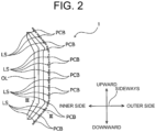
- FIG. 2 is a front view of one of the vehicle lamps 1 illustrated in FIG. 1
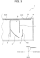
- FIG. 3 is a III-III sectional view of the vehicle lamp 1 illustrated in FIG. 2 . Note that, in FIG. 2 , illustration of a part of the configuration of a case, which is described later (refer to the reference numeral Ca), or the like, is omitted.
- the vehicle lamp 1 includes a substrate PCB on which a light source LS is mounted, a reflector R, shields S, an inner lens IL, a first plate material 10, a second plate material 20, an outer lens OL, and a case Ca.
- the substrate PCB, the reflector R, the shields S, and the inner lens IL are stored in the case Ca.
- the substrate PCB is positioned so that its normal direction is oriented sideways of the vehicle (including oblique sideway, which is oriented slightly upward or downward).
- the light source LS mounted on the substrate PCB is also oriented so that its optical axis is oriented sideways (particularly, a vehicle inner direction), and is configured to emit light in the vehicle inner direction.
- the reflector R is a reflection surface made by evaporation, painting, or the like, of aluminum or silver. The reflection surface is formed by an ellipsoid of revolution or a free form surface so as to reflect the light from the light source Ls towards the front side of the vehicle.
- the shields S guide the light reflected at the reflector R, towards the inner lens IL.
- This shields S are provided at both the inner side and the outer side of the inner lens IL.
- the shields S are also formed so that a surface thereof that faces the inner lens II, is white, or the like, for example. Accordingly, the shields S guide the light reflected at the reflector R to the inner lens IL, by reflecting the light on the inner surface thereof.
- the shields S are not limited to white, or the like, and may be formed in black, or the like, so that the light reflected at the reflector R is prevented from leaking to outside.
- the inner lens II is provided towards the front side of the vehicle relative to the reflector R, and functions as a diffusion plate to receive the light guided by the shields S and diffuse the light.
- This inner lens II is in milky white, for example.
- the first plate material 10, the second plate material 20, and the outer lens OL are layered to be in contact with one another, and are provided towards the front side of the vehicle relative to the inner lens IL.
- the first plate material 10, the second plate material 20, and the outer lens OL are located to close the opening portion of the case Ca.
- the light diffused by the inner lens IL passes through the second plate material 20, the first plate material 10, and the outer lens OL, in the stated order, to be emitted towards the front side of the vehicle.
- the first plate material 10 and the second plate material 20 have light transmissive areas and a light non-transmissive area, as described later.
- the light arrived at the first plate material 10 and the second plate material 20 from the light source LS via the inner lens IL reaches the outer lens OL via the light transmissive areas of the first plate material 10 and the second plate material 20.
- the outer lens OL is formed of a transparent resin, for example, and emits the light having passed through the light transmissive areas of the first plate material 10 and the second plate material 20, towards the front side of the vehicle.
- FIG. 4 is a plan view of the first plate material 10 illustrated in FIG. 3 , in which (a) is an overall view, and (b) is a partially enlarged view.
- the first plate material 10 has a bracket shape in planar view.
- the first plate material 10 is, as illustrated in FIG. 4(b) , made of a non-transmissive plate material through entirety of which light does not pass, and a plurality of dot-shaped through holes (e.g., 1.0 mm 2 or smaller) are formed through the non-transmissive plate material.
- the part with the through holes forms the light transmissive areas (first light transmissive areas) 11.
- the part with no through hole forms the light non-transmissive area i.e., the part between the light transmissive areas 11
- the light non-transmissive area first light non-transmissive area 12
- the light transmissive areas 11 are not limited to be those formed by through holes, and may be formed by through holes filled with light transmissive resin, for example.
- the first plate material 10 has a configuration in which through holes are provided through a non-transmissive plate material.
- the first plate material 10 may be a transmissive plate material which transmits light therethrough, on which non-transmissive paint, or the like, is printed in a mesh formation, not transmitting light therethrough.
- FIG. 5 is a plan view of the second plate material 20 illustrated in FIG. 3 , in which (a) is an overall view, (b) is a first partially enlarged view, and (c) is a second partially enlarged view.
- the second plate material 20 also has a bracket shape in planar view.
- the outer shape of the second plate material 20 matches the outer shape of the first plate material 10.
- the above-described second plate material 20 is, just as the first plate material 10, made of a non-transmissive plate material through entirety of which light does not pass, and a plurality of through holes are formed through the non-transmissive plate material.
- the second plate material 20 is divided in three areas, i.e., a dot part 20a, a line part 20b, and a large part 20c.
- the dot part 20a forms areas in which a plurality of dot-shaped through holes are formed through the non-transmissive plate material.
- the part with the through holes forms light transmissive areas (second light transmissive areas, or dot-shaped light transmissive areas) 21a.
- the part without through hole i.e., the part between the light transmissive areas 21a
- the line part 20b forms areas in which a plurality of line-shaped through holes (an exemplary shape different from a dot shape) are formed through the non-transmissive plate material.
- the part with the through holes forms light transmissive areas (second light transmissive areas, or variant light transmissive areas) 21b.
- the part without through hole i.e., the part between the light transmissive areas 21b
- the light transmissive areas 21a and 21b are not limited to be those formed by through holes, and may be formed by through holes filled with light transmissive resin, for example.
- the second plate material 20 has a configuration in which through holes are provided through a non-transmissive plate material.
- the second plate material 20 may be a transmissive plate material which transmits light therethrough, on which non-transmissive paint, or the like, is printed in a mesh formation, not transmitting light therethrough.
- each of the plurality of light transmissive areas 21a and 21b of the second plate material 20 is larger, in acreage, than each of the plurality of light transmissive areas 11 of the first plate material 10.
- each of the plurality of light transmissive areas 21a and 21b is 9 or more times larger, in acreage, than each of the plurality of light transmissive areas 11 of the first plate material 10.
- each of the plurality of light transmissive areas 21a and 21b of the second plate material 20 is less than 150 times larger (preferably, less than 50 times larger, or more preferably, less than 20 times larger), in acreage, than each of the plurality of light transmissive areas 11 of the first plate material 10.
- each of the light transmissive areas 21b of the line part 20b is larger, in acreage, than each of the light transmissive areas 21a of the dot part 20a.
- the acreage of the through hole making the large part 20c is larger than the acreage of each of the through holes making the plurality of dot-shaped light transmissive areas 21a and the plurality of line-shaped light transmissive areas 21b.
- the part with the through hole forms a light transmissive area (large light transmissive area) 21c (refer to FIG. 5(a) ).
- This light transmissive area 21c is 150 times or more larger, in acreage, than each one of the plurality of light transmissive areas 11 of the first plate material 10.
- FIG. 6 is a plan view for explaining an operation of the vehicle lamp 1 according to the present embodiment.
- FIG. 6 illustrates plate materials A to C, in which the size of a through hole of a plate material A is the same as the size of a through hole of a plate material B. Meanwhile, a through hole of the plate material C is 9 times larger, in size, than each through hole of the plate materials A and B.
- the light transmissive areas 21a are dot-shaped, and the light transmissive areas 21b are line-shaped.
- the light transmissive areas 21a and 21b are differently shaped from each other. Accordingly, while the light source LS is turned on, the way the light passing through the light transmissive areas 21a looks is different from the way the light passing through the light transmissive areas 21b looks, which is represented as a concentration difference.
- the concentration difference can be represented in three stages.
- the acreage of the light transmissive areas 21a and 21b of the second plate material 20 is less than 150 times larger (preferably, less than 50 times larger, or more preferably, less than 20 times larger) than the acreage of the light transmissive areas 11 of the first plate material 10, which makes it difficult to recognize the inside of the light chamber from outside when the light source LS is turned off and helps prevent design degradation.
- the acreages of the plurality of light transmissive areas 21a and 21b is larger than the acreages of the plurality of light transmissive areas 11. Therefore, a vehicle lamp 1 can be provided, which can prevent moire generation attributed to the same acreage among the light transmissive areas 11, 21a, 21b, thereby preventing design degradation due to generation of moire.
- the plurality of light transmissive areas 21a and 21b are 9 or more times larger, in acreage, than the plurality of light transmissive areas 11. Therefore, the acreages of the light transmissive areas 11 greatly differ from the acreages of the light transmissive areas 21a and 21b, which helps extremely prevent moire generation.
- the plurality of light transmissive areas 21a and 21b include a plurality of dot-shaped light transmissive areas 21a and a plurality of line-shaped light transmissive areas 21b differently shaped from the dot-shaped light transmissive areas 21a.
- the light transmissive areas 21a and 21b can thus represent a concentration difference therebetween, by creating a difference in transmission shape patterns. Accordingly, the design can improve.
- the following describes a vehicle lamp according to the second embodiment.
- the vehicle lamp according to the second embodiment is the same as the vehicle lamp according to the first embodiment, except part of the configuration.
- the following describes differences from the first embodiment.
- the vehicle lamp 1 according to the second embodiment includes a first plate material 30 and a second plate material 40, which are different from the counterparts of the first embodiment.
- FIG. 7 is a plan view of the first plate material 30 according to the second embodiment, in which (a) is an overall view, and (b) is a partially enlarged view.
- the first plate material 30 has a bracket shape in planar view.
- the first plate material 30 is, as illustrated in FIG. 7(b) , made of a transmissive plate material through entirety of which light passes.
- the first plate material 30 is the transmissive plate material, on which non-transmissive paint, or the like, which does not transmit light therethrough, is printed to form a plurality of dot shapes.
- the part with the non-transmissive paint, or the like forms light non-transmissive areas (first light non-transmissive areas) 31.
- the part with no non-transmissive paint, or the like (i.e., the part between the light non-transmissive areas 31) forms a light transmissive area(the first light transmissive area) 32, which transmits light therethrough.
- the first plate material 30 is formed, for example, by attaching, by an adhesive, or the like, a transmissive plate material that transmits light therethrough and a non-transmissive plate material that does not transmit light therethrough, and partially removing the non-transmissive plate material so that dot-shaped light non-transmissive areas 31 remain.
- FIG. 8 is a plan view of the second plate material 40 according to the second embodiment, in which (a) is an overall view, (b) is a first partially enlarged view, and (c) is a second partially enlarged view.
- the second plate material 40 also has a bracket shape in planar view.
- the outer shape of the second plate material 40 matches the outer shape of the first plate material 30.
- the above-described second plate material 40 is, just as the first plate material 30, made of a transmissive plate material through entirety of which light passes, on which non-transmissive paint, or the like, which does not transmit light therethrough, is printed.
- the second plate material 20 are divided in three areas, i.e., a dot part 40a, a line part 40b, and a large part 40c.
- the dot part 40a forms areas in which a plurality of dot shapes, not transmitting light therethrough, are printed on the transmissive plate material.
- the part with printed dot shapes forms light non-transmissive areas (second light non-transmissive areas, dot-shaped light non-transmissive areas) 41a.
- the part without any printed dot shape i.e., the part between the light non-transmissive areas 41a
- the line part 40b forms areas in which a plurality of line shapes (an exemplary shape different from a dot shape), not transmitting light therethrough, are printed on the transmissive plate material.
- the part with printed line shapes forms light non-transmissive areas (second light non-transmissive areas, variant light non-transmissive areas) 41b.
- the part without any printed line shape i.e., the part between light non-transmissive areas 41b
- the second plate material 40 may be also formed by layering a transmissive plate material and a non-transmissive plate material, and partially removing the non-transmissive plate material.
- the shortest distance L2 between the plurality of light non-transmissive areas 41a of the second plate material 40 and the shortest distance L3 between the plurality of light non-transmissive areas 41b of the second plate material 40 are each set longer than the shortest distance L1 (refer to FIG. 7(b) : e.g., 1 mm or smaller) between the plurality of light non-transmissive areas 31 of the first plate material 30.
- each of the shortest distance L2 between the plurality of light non-transmissive areas 41a and the shortest distance L3 between the plurality of light non-transmissive areas 41b is set 3 or more times longer than the shortest distance L1 between the plurality of light non-transmissive areas 31 of the first plate material 10.
- each of the shortest distance L2 between the plurality of light non-transmissive areas 41a of the second plate material 40 and the shortest distance L3 between the plurality of light non-transmissive areas 41b of the second plate material 40 is set is less than 150 times longer (preferably, less than 50 times longer, or more preferably, less than 20 times longer) than the shortest distance L1 between the plurality of light transmissive areas 11 of the first plate material 10.
- the shortest distance L3 between the light non-transmissive areas 41b of the line part 40b is set longer than the shortest distance L2 between the light non-transmissive areas 41a of the dot part 40a.
- the large part 40c (refer to FIG. 8(a) ) is an area through which a large through hole is formed.
- the part with the through hole forms a light transmissive area (large light transmissive area) 41c.
- the shortest distance L4 in the light transmissive area 41c is set 150 or more times longer than the shortest distance L1 between the plurality of light non-transmissive areas 31 of the first plate material 30.
- the following describes an operation of the vehicle lamp 1 according to the second embodiment.
- the shortest distance L2 between the plurality of light non-transmissive areas 41a and the shortest distance L3 between the plurality of light non-transmissive areas 41b are each set longer than the shortest distance L1 between the plurality of light non-transmissive areas 31 of the first plate material 30
- moire generation is prevented just as in the first embodiment.
- the former shortest distance L2 and L3 are each set 3 or more times longer than the latter shortest distance L1, moire generation is extremely prevented.
- the light non-transmissive areas 41a are dot-shaped, and the light non-transmissive areas 41b are line-shaped.
- the light non-transmissive areas 41a and 41b are differently shaped from each other. Accordingly, while the light source LS is turned on, the way the light passing through the light transmissive areas 42a and 42b, respectively between the light non-transmissive areas 41a and 41b, looks different, which is represented as a concentration difference.
- the concentration difference can be represented in three stages.
- the shortest distance L2 between the plurality of light non-transmissive areas 41a of the second plate material 40 and the shortest distance L3 between the plurality of light non-transmissive areas 41b of the second plate material 40 are each less than 150 times longer (preferably, less than 50 times longer, or more preferably, less than 20 times longer) than the shortest distance L1, which makes it difficult to recognize the inside of the light chamber from outside when the light source LS is turned off and helps prevent design degradation.
- the shortest distance L2 between the plurality of light non-transmissive areas 41a and the shortest distance L3 between the plurality of light non-transmissive areas 41b are each set longer than the shortest distance L1 between the plurality of light non-transmissive areas 31. Therefore, a vehicle lamp 1 can be provided, which can prevent such conditions where moire is liable to occur attributed to the shortest distances L1 to L3 respectively for the light non-transmissive areas 31, 41a, and 41b being close attributed to the shortest distances L1 to L3 being the same length, thereby preventing design degradation due to generation of moire.
- each of the shortest distance L2 between the plurality of light non-transmissive areas 41a and the shortest distance L3 between the plurality of light non-transmissive areas 41b is set 3 or more times longer than the shortest distance L1 between the plurality of light non-transmissive areas 31.
- the plurality of light non-transmissive areas 41a and 41b include a plurality of dot-shaped light non-transmissive areas 41a and a plurality of line-shaped light non-transmissive areas 41b differently shaped from the dot-shaped light non-transmissive areas 41a.
- the light transmissive areas 42a and 42b accordingly differ in shape.
- the shape pattern of light transmission differs, and thus a concentration difference is generated therebetween. Accordingly, the design can improve.
- the dot-shaped light transmissive areas 11 and 21a are regularly arranged.
- the dot-shaped light transmissive areas 11 and 21a do not have to be regularly arranged.
- all the line-shaped light transmissive areas 21b have the same longitudinal direction which is the vehicle inner direction (i.e., the inner direction of the bracket).
- not all the line-shaped light transmissive areas 21b may have the same longitudinal direction.
- each of the plurality of light transmissive areas 11 has the same acreage.
- not all the plurality of light transmissive areas 11 may have the same acreage as each other.
- those having the largest acreage and those having the smallest acreage may be, for example, within the 50% or more and 150% or less of a reference value defined based on the average or the median of the acreages of the plurality of light transmissive areas 11.
- the foregoing also applies to the plurality of light transmissive areas 21a of the second plate material 20.
- the average or the median thereof may be larger (preferably, 9 or more times larger) than the acreage of the plurality of light transmissive areas 11 of the first plate material 10.
- the acreage of the light transmissive areas 21a and 21b of the second plate material 20 may be larger (preferably, 9 or more times larger) than the average or the median of the acreages of the plurality of light transmissive areas 11 of the first plate material 10.
- the dot-shaped light non-transmissive areas 31 and 41a may be irregularly arranged, and the line-shaped light non-transmissive areas 41b do not have to have the same longitudinal direction which is the vehicle inner direction.
- the shortest distances for the plurality of light non-transmissive areas 31, and 41a and 41b do not have to be the same as each other.
- the shortest distances may be, for example, within the 50% or more and 150% or less of a reference value.
- the average or the median of the shortest distances which is made longer (e.g., 3 or more times longer), may be adopted.
- the first plate material 10 and the second plate material 20 are layered to be in contact with each other.
- the first plate material 10 and the second plate material 20 may be layered in separation from each other, with another member or a void interposed therebetween.
- the plurality of light transmissive areas 21a and 21b illustrated in FIG. 5 and the plurality of light non-transmissive areas 41a and 41b illustrated in FIG. 8 may be arranged to form a certain design, so as to make viewers recognize the certain design.
- the plurality of light transmissive areas 21a may assemble to form a substantially arrow shape, to make viewers recognize the arrow shape when the light source LS is turned on.
- the vehicle lamp 1 includes a light source LS, a reflector R, a shield S, an inner lens IL, and the like.
- the vehicle lamp 1 may have a different configuration as long as light can be irradiated on a portion emitting light as a design.
Landscapes
- Engineering & Computer Science (AREA)
- General Engineering & Computer Science (AREA)
- Mechanical Engineering (AREA)
- Physics & Mathematics (AREA)
- Microelectronics & Electronic Packaging (AREA)
- Optics & Photonics (AREA)
- Non-Portable Lighting Devices Or Systems Thereof (AREA)
- Planar Illumination Modules (AREA)
Abstract
Description
- The present invention relates to a vehicle lamp.
- Conventionally, a decorative lighting device is proposed, which includes a light non-transmissive part and a decorative part, where the light non-transmissive part is formed by a plate material through which light transmissive areas having minute dot shapes, or the like, are formed, with the other area being a light non-transmissive area, and the decorative part is formed by a plate material through which openings having a specific decorative shape are formed, and light can be irradiated from behind them (refer to
PTL 1, for example). In this decorative lighting device, for example, users can recognize the design shape according to the openings when the light source is turned on (see, for example, PTL 1). - PTL 1:
Japanese Patent Laid-open No. 2018-6026 - The applicant has been studying to apply such decorative lighting device to a vehicle lamp, and considering, in particular, to form light transmissive areas having minute dot shapes, or the like, in a decorative part, too. This is because the two plates will both have light transmissive areas having minute dot shapes, or the like, making it difficult to recognize the light chamber configuration when the light source is not turned on, thereby improving the design.
- However, such vehicle lamps sometimes cause moire due to interference between minute light transmissive areas, which improves the design quality by making it difficult to recognize the light chamber configuration, but at the same time degrading the design quality due to the moire.
- The present invention is made to solve such conventional problems, the object of which is to provide a vehicle lamp that can suppress design deterioration due to moire.
- A vehicle lamp according to the present invention includes: a first plate material that includes a plurality of first light transmissive areas transmitting light therethrough and a first light non-transmissive area positioned between the plurality of first light transmissive areas and not transmitting light therethrough; a second plate material that includes a plurality of second light transmissive areas transmitting light therethrough and a second light non-transmissive area positioned between the plurality of second light transmissive areas and not transmitting light therethrough, the second plate material being layered on the first plate material; and a light source that emits light via the plurality of first light transmissive areas of the first plate material and the plurality of second light transmissive areas of the second plate material, where the plurality of second light transmissive areas are larger, in acreage, than the plurality of first light transmissive areas.
- Another vehicle lamp according to the present invention includes: a first plate material that includes a plurality of first light non-transmissive areas not transmitting light therethrough and a first light transmissive area positioned between the plurality of first light non-transmissive areas and transmitting light therethrough; a second plate material that includes a plurality of second light non-transmissive areas not transmitting light therethrough and a second light transmissive area positioned between the plurality of second light non-transmissive areas and transmitting light therethrough, the second plate material being layered on the first plate material; and a light source that emits light via the first light transmissive area of the first plate material and the second light transmissive area of the second plate material, where a shortest distance between the plurality of second light non-transmissive areas is set longer than a shortest distance between the plurality of first light non-transmissive areas.
- The present invention provides a vehicle lamp vehicle lamp that can suppress design deterioration due to moire.
-
- [
FIG. 1] FIG. 1 is a front view of a vehicle to which a vehicle lamp according to the present embodiment is applied. - [
FIG. 2] FIG. 2 is a front view of one of the vehicle lamps illustrated inFIG. 1 . - [
FIG. 3] FIG. 3 is a III-III sectional view of the vehicle lamp illustrated inFIG. 2 . - [
FIG. 4] FIG. 4 is a plan view of a first plate material illustrated inFIG. 3 , in which (a) is an overall view, and (b) is a partially enlarged view. - [
FIG. 5] FIG. 5 is a plan view of a second plate material illustrated inFIG. 3 , in which (a) is an overall view, (b) is a first partially enlarged view, and (c) is a second partially enlarged view. - [
FIG. 6] FIG. 6 is a plan view for explaining an operation of a vehicle lamp according to the present embodiment. - [
FIG. 7] FIG. 7 is a plan view of a first plate material according to a second embodiment, in which (a) is an overall view, and (b) is a partially enlarged view. - [
FIG. 8] FIG. 8 is a plan view of a second plate material according to the second embodiment, in which (a) is an overall view, (b) is a first partially enlarged view, and (c) is a second partially enlarged view. - Hereinafter, the present invention will be described with reference to preferred embodiments. Note that the present invention is not limited to the embodiments described below and can be appropriately modified without departing from the scope of the present invention. In addition, in the embodiments described below, there are places where the illustration and description of some configurations are omitted. However, it is needless to say that known or well-known techniques are appropriately applied to the details of the omitted techniques within a range in which contradiction with the contents described below does not occur.
-
FIG. 1 is a front view of a vehicle to which a vehicle lamp according to the present embodiment is applied. As illustrated inFIG. 1 , avehicle lamp 1 according to the present embodiment is provided in a front grille G, which is between the head lamps at the front face of a vehicle V, for example. In the present embodiment, eachvehicle lamp 1 has a bracket shape in front view, and two pairs of four of thevehicle lamp 1 are provided on the left and the right, so that the pairs are symmetrical to each other, for example. -
FIG. 2 is a front view of one of thevehicle lamps 1 illustrated inFIG. 1 , andFIG. 3 is a III-III sectional view of thevehicle lamp 1 illustrated inFIG. 2 . Note that, inFIG. 2 , illustration of a part of the configuration of a case, which is described later (refer to the reference numeral Ca), or the like, is omitted. - As illustrated in
FIG. 2 andFIG. 3 , thevehicle lamp 1 includes a substrate PCB on which a light source LS is mounted, a reflector R, shields S, an inner lens IL, afirst plate material 10, asecond plate material 20, an outer lens OL, and a case Ca. The substrate PCB, the reflector R, the shields S, and the inner lens IL are stored in the case Ca. - As illustrated in
FIG. 2 andFIG. 3 , the substrate PCB is positioned so that its normal direction is oriented sideways of the vehicle (including oblique sideway, which is oriented slightly upward or downward). The light source LS mounted on the substrate PCB is also oriented so that its optical axis is oriented sideways (particularly, a vehicle inner direction), and is configured to emit light in the vehicle inner direction. The reflector R is a reflection surface made by evaporation, painting, or the like, of aluminum or silver. The reflection surface is formed by an ellipsoid of revolution or a free form surface so as to reflect the light from the light source Ls towards the front side of the vehicle. - The shields S guide the light reflected at the reflector R, towards the inner lens IL. This shields S are provided at both the inner side and the outer side of the inner lens IL. The shields S are also formed so that a surface thereof that faces the inner lens II, is white, or the like, for example. Accordingly, the shields S guide the light reflected at the reflector R to the inner lens IL, by reflecting the light on the inner surface thereof. Note that the shields S are not limited to white, or the like, and may be formed in black, or the like, so that the light reflected at the reflector R is prevented from leaking to outside.
- The inner lens II, is provided towards the front side of the vehicle relative to the reflector R, and functions as a diffusion plate to receive the light guided by the shields S and diffuse the light. This inner lens II, is in milky white, for example.
- The
first plate material 10, thesecond plate material 20, and the outer lens OL are layered to be in contact with one another, and are provided towards the front side of the vehicle relative to the inner lens IL. Thefirst plate material 10, thesecond plate material 20, and the outer lens OL are located to close the opening portion of the case Ca. The light diffused by the inner lens IL passes through thesecond plate material 20, thefirst plate material 10, and the outer lens OL, in the stated order, to be emitted towards the front side of the vehicle. - The
first plate material 10 and thesecond plate material 20 have light transmissive areas and a light non-transmissive area, as described later. The light arrived at thefirst plate material 10 and thesecond plate material 20 from the light source LS via the inner lens IL reaches the outer lens OL via the light transmissive areas of thefirst plate material 10 and thesecond plate material 20. The outer lens OL is formed of a transparent resin, for example, and emits the light having passed through the light transmissive areas of thefirst plate material 10 and thesecond plate material 20, towards the front side of the vehicle. -
FIG. 4 is a plan view of thefirst plate material 10 illustrated inFIG. 3 , in which (a) is an overall view, and (b) is a partially enlarged view. As illustrated inFIG. 4(a) , thefirst plate material 10 has a bracket shape in planar view. Thefirst plate material 10 is, as illustrated inFIG. 4(b) , made of a non-transmissive plate material through entirety of which light does not pass, and a plurality of dot-shaped through holes (e.g., 1.0 mm2 or smaller) are formed through the non-transmissive plate material. The part with the through holes forms the light transmissive areas (first light transmissive areas) 11. On the other hand, the part with no through hole forms the light non-transmissive area (i.e., the part between the light transmissive areas 11) is the light non-transmissive area (first light non-transmissive area) 12, through which light does not pass. - Note that the light
transmissive areas 11 are not limited to be those formed by through holes, and may be formed by through holes filled with light transmissive resin, for example. Furthermore, in the above-stated description, thefirst plate material 10 has a configuration in which through holes are provided through a non-transmissive plate material. However, not particularly limited to this, thefirst plate material 10 may be a transmissive plate material which transmits light therethrough, on which non-transmissive paint, or the like, is printed in a mesh formation, not transmitting light therethrough. -
FIG. 5 is a plan view of thesecond plate material 20 illustrated inFIG. 3 , in which (a) is an overall view, (b) is a first partially enlarged view, and (c) is a second partially enlarged view. As illustrated inFIG. 5(a) , thesecond plate material 20 also has a bracket shape in planar view. In particular, the outer shape of thesecond plate material 20 matches the outer shape of thefirst plate material 10. The above-describedsecond plate material 20 is, just as thefirst plate material 10, made of a non-transmissive plate material through entirety of which light does not pass, and a plurality of through holes are formed through the non-transmissive plate material. In the present embodiment, thesecond plate material 20 is divided in three areas, i.e., adot part 20a, aline part 20b, and alarge part 20c. - As illustrated in
FIG. 5(b) , thedot part 20a forms areas in which a plurality of dot-shaped through holes are formed through the non-transmissive plate material. The part with the through holes forms light transmissive areas (second light transmissive areas, or dot-shaped light transmissive areas) 21a. Meanwhile, the part without through hole (i.e., the part between thelight transmissive areas 21a) forms a light non-transmissive area (second light non-transmissive area) 22a, not transmitting light therethrough. - As illustrated in
FIG. 5(c) , theline part 20b forms areas in which a plurality of line-shaped through holes (an exemplary shape different from a dot shape) are formed through the non-transmissive plate material. The part with the through holes forms light transmissive areas (second light transmissive areas, or variant light transmissive areas) 21b. Meanwhile, the part without through hole (i.e., the part between thelight transmissive areas 21b) forms a light non-transmissive area (second light non-transmissive area) 22b, not transmitting light therethrough. - Note that the
light transmissive areas second plate material 20 has a configuration in which through holes are provided through a non-transmissive plate material. However, not particularly limited to this, thesecond plate material 20 may be a transmissive plate material which transmits light therethrough, on which non-transmissive paint, or the like, is printed in a mesh formation, not transmitting light therethrough. - In the present embodiment, each of the plurality of
light transmissive areas second plate material 20 is larger, in acreage, than each of the plurality oflight transmissive areas 11 of thefirst plate material 10. Preferably, each of the plurality oflight transmissive areas light transmissive areas 11 of thefirst plate material 10. - In addition, each of the plurality of
light transmissive areas second plate material 20 is less than 150 times larger (preferably, less than 50 times larger, or more preferably, less than 20 times larger), in acreage, than each of the plurality oflight transmissive areas 11 of thefirst plate material 10. - Note that each of the
light transmissive areas 21b of theline part 20b is larger, in acreage, than each of thelight transmissive areas 21a of thedot part 20a. - The acreage of the through hole making the
large part 20c is larger than the acreage of each of the through holes making the plurality of dot-shaped lighttransmissive areas 21a and the plurality of line-shaped lighttransmissive areas 21b. The part with the through hole forms a light transmissive area (large light transmissive area) 21c (refer toFIG. 5(a) ). Thislight transmissive area 21c is 150 times or more larger, in acreage, than each one of the plurality oflight transmissive areas 11 of thefirst plate material 10. - The following describes an operation of the
vehicle lamp 1 according to the present embodiment.FIG. 6 is a plan view for explaining an operation of thevehicle lamp 1 according to the present embodiment.FIG. 6 illustrates plate materials A to C, in which the size of a through hole of a plate material A is the same as the size of a through hole of a plate material B. Meanwhile, a through hole of the plate material C is 9 times larger, in size, than each through hole of the plate materials A and B. - When overlapping the plate materials A and B, having through holes of the same acreage, a moire is generated as illustrated in
FIG. 6 . On the contrary, when the plate material C, having 9 times larger through holes, in size, is overlapped on the plate material A, moire generation is prevented as illustrated inFIG. 6 . - Therefore, as in the above-described embodiment, when the acreage of the
light transmissive areas second plate material 20 is larger than the acreage of thelight transmissive areas 11 of thefirst plate material 10, moire generation is more prevented than in the case when the plate material A and the plate material B are overlapped on each other. When the acreage of thelight transmissive areas second plate material 20 is 9 or more time larger than the acreage of thelight transmissive areas 11 of thefirst plate material 10, moire generation is extremely prevented. - Also as illustrated in
FIG. 5(a) , in thesecond plate material 20, thelight transmissive areas 21a are dot-shaped, and thelight transmissive areas 21b are line-shaped. In other words, thelight transmissive areas light transmissive areas 21a looks is different from the way the light passing through thelight transmissive areas 21b looks, which is represented as a concentration difference. - In addition, since the
large part 20c of thesecond plate material 20 is provided with alight transmissive area 21c, which has an acreage larger than those of the dot-shaped lighttransmissive areas 21a and line-shaped lighttransmissive areas 21b, the concentration difference can be represented in three stages. - Moreover, depending on the acreage of the
light transmissive areas 11 of thefirst plate material 10, the acreage of thelight transmissive areas second plate material 20 is less than 150 times larger (preferably, less than 50 times larger, or more preferably, less than 20 times larger) than the acreage of thelight transmissive areas 11 of thefirst plate material 10, which makes it difficult to recognize the inside of the light chamber from outside when the light source LS is turned off and helps prevent design degradation. - In the above-described manner, in the
vehicle lamp 1 according to the present embodiment, the acreages of the plurality oflight transmissive areas light transmissive areas 11. Therefore, avehicle lamp 1 can be provided, which can prevent moire generation attributed to the same acreage among thelight transmissive areas - In addition, the plurality of
light transmissive areas light transmissive areas 11. Therefore, the acreages of thelight transmissive areas 11 greatly differ from the acreages of thelight transmissive areas - In addition, the plurality of
light transmissive areas transmissive areas 21a and a plurality of line-shaped lighttransmissive areas 21b differently shaped from the dot-shaped lighttransmissive areas 21a. Thelight transmissive areas - The following describes a vehicle lamp according to the second embodiment. The vehicle lamp according to the second embodiment is the same as the vehicle lamp according to the first embodiment, except part of the configuration. The following describes differences from the first embodiment.
- The
vehicle lamp 1 according to the second embodiment includes afirst plate material 30 and asecond plate material 40, which are different from the counterparts of the first embodiment. -
FIG. 7 is a plan view of thefirst plate material 30 according to the second embodiment, in which (a) is an overall view, and (b) is a partially enlarged view. As illustrated inFIG. 7(a) , thefirst plate material 30 has a bracket shape in planar view. Thefirst plate material 30 is, as illustrated inFIG. 7(b) , made of a transmissive plate material through entirety of which light passes. Thefirst plate material 30 is the transmissive plate material, on which non-transmissive paint, or the like, which does not transmit light therethrough, is printed to form a plurality of dot shapes. The part with the non-transmissive paint, or the like, forms light non-transmissive areas (first light non-transmissive areas) 31. On the other hand, the part with no non-transmissive paint, or the like, (i.e., the part between the light non-transmissive areas 31) forms a light transmissive area(the first light transmissive area) 32, which transmits light therethrough. - Note that the
first plate material 30 is formed, for example, by attaching, by an adhesive, or the like, a transmissive plate material that transmits light therethrough and a non-transmissive plate material that does not transmit light therethrough, and partially removing the non-transmissive plate material so that dot-shaped lightnon-transmissive areas 31 remain. -
FIG. 8 is a plan view of thesecond plate material 40 according to the second embodiment, in which (a) is an overall view, (b) is a first partially enlarged view, and (c) is a second partially enlarged view. As illustrated inFIG. 8(a) , thesecond plate material 40 also has a bracket shape in planar view. In particular, the outer shape of thesecond plate material 40 matches the outer shape of thefirst plate material 30. The above-describedsecond plate material 40 is, just as thefirst plate material 30, made of a transmissive plate material through entirety of which light passes, on which non-transmissive paint, or the like, which does not transmit light therethrough, is printed. In the second embodiment, thesecond plate material 20 are divided in three areas, i.e., adot part 40a, aline part 40b, and alarge part 40c. - As illustrated in
FIG. 8(b) , thedot part 40a forms areas in which a plurality of dot shapes, not transmitting light therethrough, are printed on the transmissive plate material. The part with printed dot shapes forms light non-transmissive areas (second light non-transmissive areas, dot-shaped light non-transmissive areas) 41a. Meanwhile, the part without any printed dot shape (i.e., the part between the lightnon-transmissive areas 41a) forms a light transmissive area (second light transmissive area) 42a, transmitting light therethrough. - As illustrated in
FIG. 8(c) , theline part 40b forms areas in which a plurality of line shapes (an exemplary shape different from a dot shape), not transmitting light therethrough, are printed on the transmissive plate material. The part with printed line shapes forms light non-transmissive areas (second light non-transmissive areas, variant light non-transmissive areas) 41b. Meanwhile, the part without any printed line shape (i.e., the part between lightnon-transmissive areas 41b) forms a light transmissive area (second light transmissive area) 42b, transmitting light therethrough. - Just as the
first plate material 30, thesecond plate material 40 may be also formed by layering a transmissive plate material and a non-transmissive plate material, and partially removing the non-transmissive plate material. - In the present embodiment, the shortest distance L2 between the plurality of light
non-transmissive areas 41a of thesecond plate material 40 and the shortest distance L3 between the plurality of lightnon-transmissive areas 41b of the second plate material 40 (refer toFIG. 8(b) and FIG. 8(c) ) are each set longer than the shortest distance L1 (refer toFIG. 7(b) : e.g., 1 mm or smaller) between the plurality of lightnon-transmissive areas 31 of thefirst plate material 30. Preferably, each of the shortest distance L2 between the plurality of lightnon-transmissive areas 41a and the shortest distance L3 between the plurality of lightnon-transmissive areas 41b is set 3 or more times longer than the shortest distance L1 between the plurality of lightnon-transmissive areas 31 of thefirst plate material 10. - In addition, each of the shortest distance L2 between the plurality of light
non-transmissive areas 41a of thesecond plate material 40 and the shortest distance L3 between the plurality of lightnon-transmissive areas 41b of thesecond plate material 40 is set is less than 150 times longer (preferably, less than 50 times longer, or more preferably, less than 20 times longer) than the shortest distance L1 between the plurality oflight transmissive areas 11 of thefirst plate material 10. - Note that the shortest distance L3 between the light
non-transmissive areas 41b of theline part 40b is set longer than the shortest distance L2 between the lightnon-transmissive areas 41a of thedot part 40a. - The
large part 40c (refer toFIG. 8(a) ) is an area through which a large through hole is formed. The part with the through hole forms a light transmissive area (large light transmissive area) 41c. The shortest distance L4 in thelight transmissive area 41c is set 150 or more times longer than the shortest distance L1 between the plurality of lightnon-transmissive areas 31 of thefirst plate material 30. - The following describes an operation of the
vehicle lamp 1 according to the second embodiment. First, in thesecond plate material 40, when the shortest distance L2 between the plurality of lightnon-transmissive areas 41a and the shortest distance L3 between the plurality of lightnon-transmissive areas 41b are each set longer than the shortest distance L1 between the plurality of lightnon-transmissive areas 31 of thefirst plate material 30, moire generation is prevented just as in the first embodiment. When the former shortest distance L2 and L3 are each set 3 or more times longer than the latter shortest distance L1, moire generation is extremely prevented. - In addition, in the
second plate material 40, the lightnon-transmissive areas 41a are dot-shaped, and the lightnon-transmissive areas 41b are line-shaped. In other words, the lightnon-transmissive areas light transmissive areas non-transmissive areas - In addition, since the
large part 40c of thesecond plate material 40 is provided with alight transmissive area 41c, which has the shortest distance L4 longer than the shortest distance L2 between the plurality of lightnon-transmissive areas 41a and the shortest distance L3 between the plurality of lightnon-transmissive areas 41b, the concentration difference can be represented in three stages. - Moreover, depending on the shortest distance L1 of the light
non-transmissive areas 31 of thefirst plate material 30, the shortest distance L2 between the plurality of lightnon-transmissive areas 41a of thesecond plate material 40 and the shortest distance L3 between the plurality of lightnon-transmissive areas 41b of thesecond plate material 40 are each less than 150 times longer (preferably, less than 50 times longer, or more preferably, less than 20 times longer) than the shortest distance L1, which makes it difficult to recognize the inside of the light chamber from outside when the light source LS is turned off and helps prevent design degradation. - In the above-described manner, in the
vehicle lamp 1 according to the second embodiment, the shortest distance L2 between the plurality of lightnon-transmissive areas 41a and the shortest distance L3 between the plurality of lightnon-transmissive areas 41b are each set longer than the shortest distance L1 between the plurality of lightnon-transmissive areas 31. Therefore, avehicle lamp 1 can be provided, which can prevent such conditions where moire is liable to occur attributed to the shortest distances L1 to L3 respectively for the lightnon-transmissive areas - In addition, each of the shortest distance L2 between the plurality of light
non-transmissive areas 41a and the shortest distance L3 between the plurality of lightnon-transmissive areas 41b is set 3 or more times longer than the shortest distance L1 between the plurality of lightnon-transmissive areas 31. By causing the shortest distances L1 and L2, and L3 to greatly differ from each other, the acreages of thelight transmissive areas - In addition, the plurality of light
non-transmissive areas non-transmissive areas 41a and a plurality of line-shaped lightnon-transmissive areas 41b differently shaped from the dot-shaped lightnon-transmissive areas 41a. By causing the lightnon-transmissive areas light transmissive areas - Although the present invention has been described above based on the embodiments, the present invention is not limited to the above-described embodiments, and modifications may be made without departing from the spirit of the present invention, and publicly known techniques may be combined. In addition, the techniques of the embodiments may be combined within a possible range.
- In the above-described first embodiment, the dot-shaped light
transmissive areas transmissive areas transmissive areas 21b have the same longitudinal direction which is the vehicle inner direction (i.e., the inner direction of the bracket). However, not particularly limited to this, not all the line-shaped lighttransmissive areas 21b may have the same longitudinal direction. - In addition, in the
first plate material 10, each of the plurality oflight transmissive areas 11 has the same acreage. However, not particularly limited to this, not all the plurality oflight transmissive areas 11 may have the same acreage as each other. In this case, those having the largest acreage and those having the smallest acreage may be, for example, within the 50% or more and 150% or less of a reference value defined based on the average or the median of the acreages of the plurality oflight transmissive areas 11. The foregoing also applies to the plurality oflight transmissive areas 21a of thesecond plate material 20. - When the plurality of
light transmissive areas second plate material 20 are not the same in acreage as each other, the average or the median thereof may be larger (preferably, 9 or more times larger) than the acreage of the plurality oflight transmissive areas 11 of thefirst plate material 10. Similarly, when the plurality oflight transmissive areas 11 of thefirst plate material 10 are not the same in acreage as each other, the acreage of thelight transmissive areas second plate material 20 may be larger (preferably, 9 or more times larger) than the average or the median of the acreages of the plurality oflight transmissive areas 11 of thefirst plate material 10. - The foregoing also applies to the second embodiment. The dot-shaped light
non-transmissive areas non-transmissive areas 41b do not have to have the same longitudinal direction which is the vehicle inner direction. The shortest distances for the plurality of lightnon-transmissive areas - In addition, in the
vehicle lamp 1 according to the present embodiment, thefirst plate material 10 and thesecond plate material 20 are layered to be in contact with each other. However, not particularly limited to this, thefirst plate material 10 and thesecond plate material 20 may be layered in separation from each other, with another member or a void interposed therebetween. - Furthermore, the plurality of
light transmissive areas FIG. 5 and the plurality of lightnon-transmissive areas FIG. 8 may be arranged to form a certain design, so as to make viewers recognize the certain design. For example, the plurality oflight transmissive areas 21a may assemble to form a substantially arrow shape, to make viewers recognize the arrow shape when the light source LS is turned on. - Moreover, as illustrated in
FIG. 3 , thevehicle lamp 1 according to the present embodiment includes a light source LS, a reflector R, a shield S, an inner lens IL, and the like. However, not particularly limited to this, thevehicle lamp 1 may have a different configuration as long as light can be irradiated on a portion emitting light as a design. -
- 1: Vehicle lamp
- 10: First plate material
- 11: Light transmissive areas (first light transmissive areas)
- 12: Light non-transmissive area (first light non-transmissive area)
- 20: Second plate material
- 21a: Light transmissive areas (second light transmissive areas, dot-shaped light transmissive areas)
- 21b: Light transmissive areas (second light transmissive areas, variant light transmissive areas)
- 22a, 22b: Light non-transmissive area (second light non-transmissive area)
- 30: First plate material
- 31: Light non-transmissive areas (first light non-transmissive areas)
- 32: Light transmissive area (first light transmissive area)
- 40: Second plate material
- 41a: Light non-transmissive areas (second light non-transmissive areas, dot-shaped light non-transmissive areas)
- 41b: Light non-transmissive areas (second light non-transmissive areas, variant light non-transmissive areas)
- 42a, 42b: light transmissive area (second light transmissive area)
- L1 to L4: Shortest distance
- LS: Light source
Claims (6)
- A vehicle lamp (1) comprising:a first plate material (10) that includes a plurality of first light transmissive areas (11) transmitting light therethrough and a first light non-transmissive area (12) positioned between the plurality of first light transmissive areas (11) and not transmitting light therethrough;a second plate material (20) that includes a plurality of second light transmissive areas (21a; 21b) transmitting light therethrough and a second light non-transmissive area (22a; 22b) positioned between the plurality of second light transmissive areas (21a; 21b) and not transmitting light therethrough, the second plate material (20) being layered on the first plate material (10); anda light source (LS) that emits light via the plurality of first light transmissive areas (11) of the first plate material (10) and the plurality of second light transmissive areas (21a; 21b) of the second plate material (20), whereinthe plurality of second light transmissive areas (21a; 21b) are larger, in acreage, than the plurality of first light transmissive areas (11).
- The vehicle lamp (1) according to Claim 1, wherein
the plurality of second light transmissive areas (21a; 21b) are 9 or more times larger, in acreage, than the plurality of first light transmissive areas (11). - The vehicle lamp (1) according to Claim 1, wherein
the plurality of second light transmissive areas (21a; 21b) include a plurality of dot-shaped light transmissive areas (21a) and a plurality of variant light transmissive areas (21b) differently shaped from the plurality of dot-shaped light transmissive areas (21a). - A vehicle lamp (1) comprising:a first plate material (30) that includes a plurality of first light non-transmissive areas (31) not transmitting light therethrough and a first light transmissive area (32) positioned between the plurality of first light non-transmissive areas (31) and transmitting light therethrough;a second plate material (40) that includes a plurality of second light non-transmissive areas (41a; 41b) not transmitting light therethrough and a second light transmissive area (42a; 42b) positioned between the plurality of second light non-transmissive areas (41a; 41b) and transmitting light therethrough, the second plate material (40) being layered on the first plate material (30); anda light source (LS) that emits light via the first light transmissive area (32) of the first plate material (30) and the second light transmissive area (42a; 42b) of the second plate material (40), whereina shortest distance between the plurality of second light non-transmissive areas (41a; 41b) is set longer than a shortest distance between the plurality of first light non-transmissive areas (31).
- The vehicle lamp (1) according to Claim 4, wherein
the shortest distance between the plurality of second light non-transmissive areas (41a; 41b) of the second plate material (40) is set 3 or more times longer than the shortest distance between the plurality of first light non-transmissive areas (31) of the first plate material (30). - The vehicle lamp (1) according to Claim 4, wherein
the plurality of second light non-transmissive areas (41a; 41b) include a plurality of dot-shaped light non-transmissive areas (41a) and a plurality of variant light non-transmissive areas (41b) differently shaped from the plurality of dot-shaped light non-transmissive areas (41a).
Applications Claiming Priority (2)
| Application Number | Priority Date | Filing Date | Title |
|---|---|---|---|
| JP2021040634A JP7604962B2 (en) | 2021-03-12 | 2021-03-12 | Vehicle lighting fixtures |
| PCT/JP2022/010546 WO2022191275A1 (en) | 2021-03-12 | 2022-03-10 | Vehicle lamp |
Publications (2)
| Publication Number | Publication Date |
|---|---|
| EP4306848A1 true EP4306848A1 (en) | 2024-01-17 |
| EP4306848A4 EP4306848A4 (en) | 2024-10-09 |
Family
ID=83228009
Family Applications (1)
| Application Number | Title | Priority Date | Filing Date |
|---|---|---|---|
| EP22767229.2A Pending EP4306848A4 (en) | 2021-03-12 | 2022-03-10 | VEHICLE LAMP |
Country Status (5)
| Country | Link |
|---|---|
| US (1) | US12092286B2 (en) |
| EP (1) | EP4306848A4 (en) |
| JP (1) | JP7604962B2 (en) |
| CN (1) | CN116964379A (en) |
| WO (1) | WO2022191275A1 (en) |
Cited By (1)
| Publication number | Priority date | Publication date | Assignee | Title |
|---|---|---|---|---|
| FR3159216A1 (en) * | 2024-07-18 | 2025-08-15 | Valeo Vision | Lighting and/or signaling device of a motor vehicle |
Family Cites Families (11)
| Publication number | Priority date | Publication date | Assignee | Title |
|---|---|---|---|---|
| GB9706887D0 (en) * | 1997-04-04 | 1997-05-21 | Britax Vega Ltd | Vehicle signal lamp |
| DE102004010974B4 (en) * | 2004-03-03 | 2010-01-21 | Johnson Controls Gmbh | Lighting component, in particular for search and function lighting and in particular for a vehicle |
| DE102004061691A1 (en) * | 2004-12-22 | 2006-07-06 | Daimlerchrysler Ag | Motor vehicle rear light has transparent reflector plate with fitted triple reflectors or prisms, perforated plate with openings associated with gaps between reflectors and between light emitting diodes |
| JP5342127B2 (en) | 2007-02-28 | 2013-11-13 | 富士重工業株式会社 | Light emitting device |
| JP2011013286A (en) * | 2009-06-30 | 2011-01-20 | Harison Toshiba Lighting Corp | Illuminator |
| JP6223746B2 (en) * | 2013-08-26 | 2017-11-01 | 株式会社東芝 | Single-sided light-emitting transparent light guide plate and surface light-emitting device using this light guide plate |
| JP2018006026A (en) | 2016-06-28 | 2018-01-11 | 株式会社小糸製作所 | Decorative lighting device |
| DE102016217949B4 (en) * | 2016-09-20 | 2023-11-23 | Faurecia Innenraum Systeme Gmbh | Vehicle interior trim part and lighting element |
| JP6938271B2 (en) * | 2017-08-10 | 2021-09-22 | パイオニア株式会社 | Light emitting device |
| CN112424855B (en) * | 2018-08-22 | 2024-09-06 | 大日本印刷株式会社 | Decorative sheet and display device |
| DE102018124384A1 (en) * | 2018-10-02 | 2020-04-02 | Rehau Ag + Co | Radiolucent trim part for a motor vehicle and method for producing a trim part |
-
2021
- 2021-03-12 JP JP2021040634A patent/JP7604962B2/en active Active
-
2022
- 2022-03-10 US US18/548,959 patent/US12092286B2/en active Active
- 2022-03-10 EP EP22767229.2A patent/EP4306848A4/en active Pending
- 2022-03-10 WO PCT/JP2022/010546 patent/WO2022191275A1/en not_active Ceased
- 2022-03-10 CN CN202280019529.0A patent/CN116964379A/en active Pending
Cited By (1)
| Publication number | Priority date | Publication date | Assignee | Title |
|---|---|---|---|---|
| FR3159216A1 (en) * | 2024-07-18 | 2025-08-15 | Valeo Vision | Lighting and/or signaling device of a motor vehicle |
Also Published As
| Publication number | Publication date |
|---|---|
| JP7604962B2 (en) | 2024-12-24 |
| CN116964379A (en) | 2023-10-27 |
| US12092286B2 (en) | 2024-09-17 |
| EP4306848A4 (en) | 2024-10-09 |
| WO2022191275A1 (en) | 2022-09-15 |
| JP2022140010A (en) | 2022-09-26 |
| US20240151383A1 (en) | 2024-05-09 |
Similar Documents
| Publication | Publication Date | Title |
|---|---|---|
| EP4283189B1 (en) | Vehicle lighting | |
| KR20130011779A (en) | Lamp assembly | |
| US12281774B2 (en) | Vehicle lamp having excitation light source, light conversion unit, and red lens | |
| EP4306848A1 (en) | Vehicle lamp | |
| JP2020155352A (en) | Vehicle lighting | |
| JP4949051B2 (en) | Vehicle lighting device | |
| JP6659348B2 (en) | Window rear lamp | |
| US20250277569A1 (en) | Vehicle lamp | |
| JP2018026192A (en) | Vehicle lighting | |
| JP7579709B2 (en) | Vehicle lighting fixtures | |
| EP4261455B1 (en) | Lighting device for vehicle | |
| EP3733454B1 (en) | Vehicle interior lamp | |
| JP2013171813A (en) | Vehicle lighting | |
| EP3912862B1 (en) | Vehicle lamp and headlamp assembly | |
| JP7633136B2 (en) | Vehicle lighting fixtures | |
| JP7483586B2 (en) | Vehicle lighting fixtures | |
| JP5977872B2 (en) | Vehicle lighting | |
| KR20140011637A (en) | Plane light source apparatus | |
| WO2022004287A1 (en) | Vehicle lamp fitting | |
| JP7193276B2 (en) | vehicle lamp | |
| CN111406179B (en) | Illuminating device | |
| WO2025057697A1 (en) | Lamp fitting for drawing | |
| JP2025170970A (en) | emblem | |
| WO2023074753A1 (en) | Vehicle lamp fitting | |
| JP2024070428A (en) | Vehicle Lighting |
Legal Events
| Date | Code | Title | Description |
|---|---|---|---|
| STAA | Information on the status of an ep patent application or granted ep patent |
Free format text: STATUS: THE INTERNATIONAL PUBLICATION HAS BEEN MADE |
|
| PUAI | Public reference made under article 153(3) epc to a published international application that has entered the european phase |
Free format text: ORIGINAL CODE: 0009012 |
|
| STAA | Information on the status of an ep patent application or granted ep patent |
Free format text: STATUS: REQUEST FOR EXAMINATION WAS MADE |
|
| 17P | Request for examination filed |
Effective date: 20230907 |
|
| AK | Designated contracting states |
Kind code of ref document: A1 Designated state(s): AL AT BE BG CH CY CZ DE DK EE ES FI FR GB GR HR HU IE IS IT LI LT LU LV MC MK MT NL NO PL PT RO RS SE SI SK SM TR |
|
| DAV | Request for validation of the european patent (deleted) | ||
| DAX | Request for extension of the european patent (deleted) | ||
| A4 | Supplementary search report drawn up and despatched |
Effective date: 20240905 |
|
| RIC1 | Information provided on ipc code assigned before grant |
Ipc: F21S 43/40 20180101ALI20240830BHEP Ipc: F21S 43/31 20180101ALI20240830BHEP Ipc: B60Q 1/26 20060101ALI20240830BHEP Ipc: B60Q 1/00 20060101ALI20240830BHEP Ipc: B32B 27/08 20060101ALI20240830BHEP Ipc: F21S 43/50 20180101ALI20240830BHEP Ipc: F21S 43/20 20180101ALI20240830BHEP Ipc: F21W 104/00 20180101ALI20240830BHEP Ipc: F21S 2/00 20160101ALI20240830BHEP Ipc: F21V 11/14 20060101AFI20240830BHEP |
|
| STAA | Information on the status of an ep patent application or granted ep patent |
Free format text: STATUS: EXAMINATION IS IN PROGRESS |
|
| 17Q | First examination report despatched |
Effective date: 20260216 |