EP4306843A1 - Triple-wall tank - Google Patents
Triple-wall tank Download PDFInfo
- Publication number
- EP4306843A1 EP4306843A1 EP22766939.7A EP22766939A EP4306843A1 EP 4306843 A1 EP4306843 A1 EP 4306843A1 EP 22766939 A EP22766939 A EP 22766939A EP 4306843 A1 EP4306843 A1 EP 4306843A1
- Authority
- EP
- European Patent Office
- Prior art keywords
- tank
- pipe
- expandable
- joined
- inner tank
- Prior art date
- Legal status (The legal status is an assumption and is not a legal conclusion. Google has not performed a legal analysis and makes no representation as to the accuracy of the status listed.)
- Pending
Links
Images

Classifications
-
- F—MECHANICAL ENGINEERING; LIGHTING; HEATING; WEAPONS; BLASTING
- F17—STORING OR DISTRIBUTING GASES OR LIQUIDS
- F17C—VESSELS FOR CONTAINING OR STORING COMPRESSED, LIQUEFIED OR SOLIDIFIED GASES; FIXED-CAPACITY GAS-HOLDERS; FILLING VESSELS WITH, OR DISCHARGING FROM VESSELS, COMPRESSED, LIQUEFIED, OR SOLIDIFIED GASES
- F17C3/00—Vessels not under pressure
- F17C3/02—Vessels not under pressure with provision for thermal insulation
- F17C3/04—Vessels not under pressure with provision for thermal insulation by insulating layers
-
- F—MECHANICAL ENGINEERING; LIGHTING; HEATING; WEAPONS; BLASTING
- F17—STORING OR DISTRIBUTING GASES OR LIQUIDS
- F17C—VESSELS FOR CONTAINING OR STORING COMPRESSED, LIQUEFIED OR SOLIDIFIED GASES; FIXED-CAPACITY GAS-HOLDERS; FILLING VESSELS WITH, OR DISCHARGING FROM VESSELS, COMPRESSED, LIQUEFIED, OR SOLIDIFIED GASES
- F17C13/00—Details of vessels or of the filling or discharging of vessels
- F17C13/001—Thermal insulation specially adapted for cryogenic vessels
-
- F—MECHANICAL ENGINEERING; LIGHTING; HEATING; WEAPONS; BLASTING
- F16—ENGINEERING ELEMENTS AND UNITS; GENERAL MEASURES FOR PRODUCING AND MAINTAINING EFFECTIVE FUNCTIONING OF MACHINES OR INSTALLATIONS; THERMAL INSULATION IN GENERAL
- F16L—PIPES; JOINTS OR FITTINGS FOR PIPES; SUPPORTS FOR PIPES, CABLES OR PROTECTIVE TUBING; MEANS FOR THERMAL INSULATION IN GENERAL
- F16L41/00—Branching pipes; Joining pipes to walls
- F16L41/08—Joining pipes to walls or pipes, the joined pipe axis being perpendicular to the plane of a wall or to the axis of another pipe
- F16L41/082—Non-disconnectable joints, e.g. soldered, adhesive or caulked joints
- F16L41/084—Soldered joints
-
- F—MECHANICAL ENGINEERING; LIGHTING; HEATING; WEAPONS; BLASTING
- F17—STORING OR DISTRIBUTING GASES OR LIQUIDS
- F17C—VESSELS FOR CONTAINING OR STORING COMPRESSED, LIQUEFIED OR SOLIDIFIED GASES; FIXED-CAPACITY GAS-HOLDERS; FILLING VESSELS WITH, OR DISCHARGING FROM VESSELS, COMPRESSED, LIQUEFIED, OR SOLIDIFIED GASES
- F17C2201/00—Vessel construction, in particular geometry, arrangement or size
- F17C2201/01—Shape
- F17C2201/0104—Shape cylindrical
- F17C2201/0109—Shape cylindrical with exteriorly curved end-piece
-
- F—MECHANICAL ENGINEERING; LIGHTING; HEATING; WEAPONS; BLASTING
- F17—STORING OR DISTRIBUTING GASES OR LIQUIDS
- F17C—VESSELS FOR CONTAINING OR STORING COMPRESSED, LIQUEFIED OR SOLIDIFIED GASES; FIXED-CAPACITY GAS-HOLDERS; FILLING VESSELS WITH, OR DISCHARGING FROM VESSELS, COMPRESSED, LIQUEFIED, OR SOLIDIFIED GASES
- F17C2201/00—Vessel construction, in particular geometry, arrangement or size
- F17C2201/01—Shape
- F17C2201/0104—Shape cylindrical
- F17C2201/0119—Shape cylindrical with flat end-piece
-
- F—MECHANICAL ENGINEERING; LIGHTING; HEATING; WEAPONS; BLASTING
- F17—STORING OR DISTRIBUTING GASES OR LIQUIDS
- F17C—VESSELS FOR CONTAINING OR STORING COMPRESSED, LIQUEFIED OR SOLIDIFIED GASES; FIXED-CAPACITY GAS-HOLDERS; FILLING VESSELS WITH, OR DISCHARGING FROM VESSELS, COMPRESSED, LIQUEFIED, OR SOLIDIFIED GASES
- F17C2201/00—Vessel construction, in particular geometry, arrangement or size
- F17C2201/03—Orientation
- F17C2201/032—Orientation with substantially vertical main axis
-
- F—MECHANICAL ENGINEERING; LIGHTING; HEATING; WEAPONS; BLASTING
- F17—STORING OR DISTRIBUTING GASES OR LIQUIDS
- F17C—VESSELS FOR CONTAINING OR STORING COMPRESSED, LIQUEFIED OR SOLIDIFIED GASES; FIXED-CAPACITY GAS-HOLDERS; FILLING VESSELS WITH, OR DISCHARGING FROM VESSELS, COMPRESSED, LIQUEFIED, OR SOLIDIFIED GASES
- F17C2201/00—Vessel construction, in particular geometry, arrangement or size
- F17C2201/05—Size
- F17C2201/052—Size large (>1000 m3)
-
- F—MECHANICAL ENGINEERING; LIGHTING; HEATING; WEAPONS; BLASTING
- F17—STORING OR DISTRIBUTING GASES OR LIQUIDS
- F17C—VESSELS FOR CONTAINING OR STORING COMPRESSED, LIQUEFIED OR SOLIDIFIED GASES; FIXED-CAPACITY GAS-HOLDERS; FILLING VESSELS WITH, OR DISCHARGING FROM VESSELS, COMPRESSED, LIQUEFIED, OR SOLIDIFIED GASES
- F17C2201/00—Vessel construction, in particular geometry, arrangement or size
- F17C2201/05—Size
- F17C2201/054—Size medium (>1 m3)
-
- F—MECHANICAL ENGINEERING; LIGHTING; HEATING; WEAPONS; BLASTING
- F17—STORING OR DISTRIBUTING GASES OR LIQUIDS
- F17C—VESSELS FOR CONTAINING OR STORING COMPRESSED, LIQUEFIED OR SOLIDIFIED GASES; FIXED-CAPACITY GAS-HOLDERS; FILLING VESSELS WITH, OR DISCHARGING FROM VESSELS, COMPRESSED, LIQUEFIED, OR SOLIDIFIED GASES
- F17C2203/00—Vessel construction, in particular walls or details thereof
- F17C2203/03—Thermal insulations
- F17C2203/0304—Thermal insulations by solid means
- F17C2203/0337—Granular
- F17C2203/0341—Perlite
-
- F—MECHANICAL ENGINEERING; LIGHTING; HEATING; WEAPONS; BLASTING
- F17—STORING OR DISTRIBUTING GASES OR LIQUIDS
- F17C—VESSELS FOR CONTAINING OR STORING COMPRESSED, LIQUEFIED OR SOLIDIFIED GASES; FIXED-CAPACITY GAS-HOLDERS; FILLING VESSELS WITH, OR DISCHARGING FROM VESSELS, COMPRESSED, LIQUEFIED, OR SOLIDIFIED GASES
- F17C2203/00—Vessel construction, in particular walls or details thereof
- F17C2203/03—Thermal insulations
- F17C2203/0304—Thermal insulations by solid means
- F17C2203/0345—Fibres
- F17C2203/035—Glass wool
-
- F—MECHANICAL ENGINEERING; LIGHTING; HEATING; WEAPONS; BLASTING
- F17—STORING OR DISTRIBUTING GASES OR LIQUIDS
- F17C—VESSELS FOR CONTAINING OR STORING COMPRESSED, LIQUEFIED OR SOLIDIFIED GASES; FIXED-CAPACITY GAS-HOLDERS; FILLING VESSELS WITH, OR DISCHARGING FROM VESSELS, COMPRESSED, LIQUEFIED, OR SOLIDIFIED GASES
- F17C2203/00—Vessel construction, in particular walls or details thereof
- F17C2203/06—Materials for walls or layers thereof; Properties or structures of walls or their materials
- F17C2203/0602—Wall structures; Special features thereof
- F17C2203/0612—Wall structures
- F17C2203/0626—Multiple walls
- F17C2203/0631—Three or more walls
-
- F—MECHANICAL ENGINEERING; LIGHTING; HEATING; WEAPONS; BLASTING
- F17—STORING OR DISTRIBUTING GASES OR LIQUIDS
- F17C—VESSELS FOR CONTAINING OR STORING COMPRESSED, LIQUEFIED OR SOLIDIFIED GASES; FIXED-CAPACITY GAS-HOLDERS; FILLING VESSELS WITH, OR DISCHARGING FROM VESSELS, COMPRESSED, LIQUEFIED, OR SOLIDIFIED GASES
- F17C2203/00—Vessel construction, in particular walls or details thereof
- F17C2203/06—Materials for walls or layers thereof; Properties or structures of walls or their materials
- F17C2203/0634—Materials for walls or layers thereof
- F17C2203/0678—Concrete
-
- F—MECHANICAL ENGINEERING; LIGHTING; HEATING; WEAPONS; BLASTING
- F17—STORING OR DISTRIBUTING GASES OR LIQUIDS
- F17C—VESSELS FOR CONTAINING OR STORING COMPRESSED, LIQUEFIED OR SOLIDIFIED GASES; FIXED-CAPACITY GAS-HOLDERS; FILLING VESSELS WITH, OR DISCHARGING FROM VESSELS, COMPRESSED, LIQUEFIED, OR SOLIDIFIED GASES
- F17C2205/00—Vessel construction, in particular mounting arrangements, attachments or identifications means
- F17C2205/03—Fluid connections, filters, valves, closure means or other attachments
- F17C2205/0302—Fittings, valves, filters, or components in connection with the gas storage device
- F17C2205/0341—Filters
-
- F—MECHANICAL ENGINEERING; LIGHTING; HEATING; WEAPONS; BLASTING
- F17—STORING OR DISTRIBUTING GASES OR LIQUIDS
- F17C—VESSELS FOR CONTAINING OR STORING COMPRESSED, LIQUEFIED OR SOLIDIFIED GASES; FIXED-CAPACITY GAS-HOLDERS; FILLING VESSELS WITH, OR DISCHARGING FROM VESSELS, COMPRESSED, LIQUEFIED, OR SOLIDIFIED GASES
- F17C2205/00—Vessel construction, in particular mounting arrangements, attachments or identifications means
- F17C2205/03—Fluid connections, filters, valves, closure means or other attachments
- F17C2205/0302—Fittings, valves, filters, or components in connection with the gas storage device
- F17C2205/0352—Pipes
- F17C2205/0361—Pipes corrugated
-
- F—MECHANICAL ENGINEERING; LIGHTING; HEATING; WEAPONS; BLASTING
- F17—STORING OR DISTRIBUTING GASES OR LIQUIDS
- F17C—VESSELS FOR CONTAINING OR STORING COMPRESSED, LIQUEFIED OR SOLIDIFIED GASES; FIXED-CAPACITY GAS-HOLDERS; FILLING VESSELS WITH, OR DISCHARGING FROM VESSELS, COMPRESSED, LIQUEFIED, OR SOLIDIFIED GASES
- F17C2221/00—Handled fluid, in particular type of fluid
- F17C2221/01—Pure fluids
- F17C2221/012—Hydrogen
-
- F—MECHANICAL ENGINEERING; LIGHTING; HEATING; WEAPONS; BLASTING
- F17—STORING OR DISTRIBUTING GASES OR LIQUIDS
- F17C—VESSELS FOR CONTAINING OR STORING COMPRESSED, LIQUEFIED OR SOLIDIFIED GASES; FIXED-CAPACITY GAS-HOLDERS; FILLING VESSELS WITH, OR DISCHARGING FROM VESSELS, COMPRESSED, LIQUEFIED, OR SOLIDIFIED GASES
- F17C2221/00—Handled fluid, in particular type of fluid
- F17C2221/01—Pure fluids
- F17C2221/014—Nitrogen
-
- F—MECHANICAL ENGINEERING; LIGHTING; HEATING; WEAPONS; BLASTING
- F17—STORING OR DISTRIBUTING GASES OR LIQUIDS
- F17C—VESSELS FOR CONTAINING OR STORING COMPRESSED, LIQUEFIED OR SOLIDIFIED GASES; FIXED-CAPACITY GAS-HOLDERS; FILLING VESSELS WITH, OR DISCHARGING FROM VESSELS, COMPRESSED, LIQUEFIED, OR SOLIDIFIED GASES
- F17C2221/00—Handled fluid, in particular type of fluid
- F17C2221/01—Pure fluids
- F17C2221/016—Noble gases (Ar, Kr, Xe)
- F17C2221/017—Helium
-
- F—MECHANICAL ENGINEERING; LIGHTING; HEATING; WEAPONS; BLASTING
- F17—STORING OR DISTRIBUTING GASES OR LIQUIDS
- F17C—VESSELS FOR CONTAINING OR STORING COMPRESSED, LIQUEFIED OR SOLIDIFIED GASES; FIXED-CAPACITY GAS-HOLDERS; FILLING VESSELS WITH, OR DISCHARGING FROM VESSELS, COMPRESSED, LIQUEFIED, OR SOLIDIFIED GASES
- F17C2221/00—Handled fluid, in particular type of fluid
- F17C2221/03—Mixtures
- F17C2221/032—Hydrocarbons
- F17C2221/033—Methane, e.g. natural gas, CNG, LNG, GNL, GNC, PLNG
-
- F—MECHANICAL ENGINEERING; LIGHTING; HEATING; WEAPONS; BLASTING
- F17—STORING OR DISTRIBUTING GASES OR LIQUIDS
- F17C—VESSELS FOR CONTAINING OR STORING COMPRESSED, LIQUEFIED OR SOLIDIFIED GASES; FIXED-CAPACITY GAS-HOLDERS; FILLING VESSELS WITH, OR DISCHARGING FROM VESSELS, COMPRESSED, LIQUEFIED, OR SOLIDIFIED GASES
- F17C2221/00—Handled fluid, in particular type of fluid
- F17C2221/03—Mixtures
- F17C2221/032—Hydrocarbons
- F17C2221/035—Propane butane, e.g. LPG, GPL
-
- F—MECHANICAL ENGINEERING; LIGHTING; HEATING; WEAPONS; BLASTING
- F17—STORING OR DISTRIBUTING GASES OR LIQUIDS
- F17C—VESSELS FOR CONTAINING OR STORING COMPRESSED, LIQUEFIED OR SOLIDIFIED GASES; FIXED-CAPACITY GAS-HOLDERS; FILLING VESSELS WITH, OR DISCHARGING FROM VESSELS, COMPRESSED, LIQUEFIED, OR SOLIDIFIED GASES
- F17C2223/00—Handled fluid before transfer, i.e. state of fluid when stored in the vessel or before transfer from the vessel
- F17C2223/01—Handled fluid before transfer, i.e. state of fluid when stored in the vessel or before transfer from the vessel characterised by the phase
- F17C2223/0146—Two-phase
- F17C2223/0153—Liquefied gas, e.g. LPG, GPL
- F17C2223/0161—Liquefied gas, e.g. LPG, GPL cryogenic, e.g. LNG, GNL, PLNG
-
- F—MECHANICAL ENGINEERING; LIGHTING; HEATING; WEAPONS; BLASTING
- F17—STORING OR DISTRIBUTING GASES OR LIQUIDS
- F17C—VESSELS FOR CONTAINING OR STORING COMPRESSED, LIQUEFIED OR SOLIDIFIED GASES; FIXED-CAPACITY GAS-HOLDERS; FILLING VESSELS WITH, OR DISCHARGING FROM VESSELS, COMPRESSED, LIQUEFIED, OR SOLIDIFIED GASES
- F17C2223/00—Handled fluid before transfer, i.e. state of fluid when stored in the vessel or before transfer from the vessel
- F17C2223/03—Handled fluid before transfer, i.e. state of fluid when stored in the vessel or before transfer from the vessel characterised by the pressure level
- F17C2223/033—Small pressure, e.g. for liquefied gas
-
- F—MECHANICAL ENGINEERING; LIGHTING; HEATING; WEAPONS; BLASTING
- F17—STORING OR DISTRIBUTING GASES OR LIQUIDS
- F17C—VESSELS FOR CONTAINING OR STORING COMPRESSED, LIQUEFIED OR SOLIDIFIED GASES; FIXED-CAPACITY GAS-HOLDERS; FILLING VESSELS WITH, OR DISCHARGING FROM VESSELS, COMPRESSED, LIQUEFIED, OR SOLIDIFIED GASES
- F17C2260/00—Purposes of gas storage and gas handling
- F17C2260/01—Improving mechanical properties or manufacturing
-
- F—MECHANICAL ENGINEERING; LIGHTING; HEATING; WEAPONS; BLASTING
- F17—STORING OR DISTRIBUTING GASES OR LIQUIDS
- F17C—VESSELS FOR CONTAINING OR STORING COMPRESSED, LIQUEFIED OR SOLIDIFIED GASES; FIXED-CAPACITY GAS-HOLDERS; FILLING VESSELS WITH, OR DISCHARGING FROM VESSELS, COMPRESSED, LIQUEFIED, OR SOLIDIFIED GASES
- F17C2270/00—Applications
- F17C2270/01—Applications for fluid transport or storage
- F17C2270/0134—Applications for fluid transport or storage placed above the ground
Definitions
- the present disclosure relates to a triple containment tank that stores a low temperature liquefied gas, particularly to a support structure for a nozzle that penetrates a triple shell.
- Double-shell tanks that store a low temperature liquefied gas have been known.
- the double-shell tank includes: a double shell including an inner tank and an outer tank; and an insulation filled in between the inner tank and the outer tank.
- the double-shell tank includes a pipe through which a low temperature liquid stored in the inner tank is discharged to an outside of the tank. Such pipe penetrates both of the inner tank and the outer tank.
- each of PTLs 1 and 2 proposes a support structure for a pipe in a double-shell tank.
- a nozzle for liquid injection and discharge penetrates a roof of the inner tank and a roof of the outer tank.
- the nozzle is supported by the roof of the outer tank by being suspended from the roof of the outer tank and is hermetically coupled to the roof of the inner tank through a bellows.
- a liquid delivering nozzle penetrates a roof of the inner tank and a roof of the outer tank, and an outer barrel of the nozzle is coupled to a portion of the roof of the inner tank which is lower in rigidity than the other portion of the roof of the inner tank.
- the roof of the outer tank and the outer barrel are coupled to each other through a bellows, and the outer barrel is mounted on a support base located at a bottom plate of the inner tank.
- Triple containment tanks in which an intermediate tank is further added between the inner tank and outer tank of the double-shell tank are also known.
- the triple containment tank when a low temperature liquefied gas is stored in the inner tank, inter-tank distances of the inner tank, the intermediate tank, and the outer tank change by thermal contraction. Since the temperatures of the inner tank, the intermediate tank, and the outer tank are different from each other, the degrees of change of the inter-tank distances of the respective tanks are also different from each other.
- Each of PTLs 1 and 2 merely discloses a pipe support structure in the double-shell tank including the inner tank and the outer tank. Moreover, each of PTLs 1 and 2 does not disclose a relationship between the intermediate tank and the pipe. Therefore, the pipe support structure disclosed in each of PTLs 1 and 2 cannot be applied to the triple containment tank.
- the present disclosure was made under these circumstances, and an object of the present disclosure is to propose, in a triple containment tank including a triple shell including an inner tank, an intermediate tank, and an outer tank, a support structure for a pipe penetrating the triple shell.
- a triple containment tank includes:
- a triple containment tank includes:
- the support structure for the pipe which is included in the triple containment tank configured as above is a structure suitable for supporting the pipe penetrating the triple shell of the triple containment tank including the triple shell including the inner tank, the intermediate tank, and the outer tank.
- the present disclosure can propose, in a triple containment tank including a triple shell including an inner tank, an intermediate tank, and an outer tank, a support structure for a pipe penetrating the triple shell.
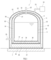
- FIG. 1 is a sectional view showing an entire configuration of a triple containment tank 1 according to the embodiment of the present disclosure.
- the triple containment tank 1 shown in FIG. 1 is a stationary flat-bottomed triple containment tank placed on the ground.
- the triple containment tank 1 includes: a tank foundation 7 made of concrete; an outer tank 5 located on the tank foundation 7; an intermediate tank 4 located inside the outer tank 5; and an inner tank 3 located inside the intermediate tank 4.
- the outer tank 5, the intermediate tank 4, and the inner tank 3 form a triple shell.
- the inner tank 3 is a container that stores a low temperature liquefied gas.
- the low temperature liquefied gas include liquid helium, liquid hydrogen, liquid nitrogen, LNG, and LPG.
- the inner tank 3 includes: a substantially flat inner tank bottom plate 31; a cylindrical inner tank side plate 32 standing from the inner tank bottom plate 31; and an inner tank roof 33 located at an upper portion of the inner tank side plate 32.
- the inner tank side plate 32 and the tank foundation 7 may be coupled to each other by, for example, mooring members, such as anchor straps, located around the inner tank 3 at substantially regular intervals.
- the intermediate tank 4 surrounds the inner tank 3.
- the intermediate tank 4 includes: a substantially flat intermediate tank bottom plate 41; a cylindrical intermediate tank side plate 42 standing from the intermediate tank bottom plate 41; and an intermediate tank roof 43 located at an upper portion of the intermediate tank side plate 42.
- a level concrete layer 35 and an inner bottom insulation layer 36 are located between the intermediate tank bottom plate 41 and the inner tank bottom plate 31 in an upper-lower direction.
- the intermediate tank roof 43 may support the inner tank roof 33.
- the inner tank roof 33 may be a suspended roof.
- the intermediate tank side plate 42 and the tank foundation 7 may be coupled to each other by, for example, mooring members, such as anchor straps, located around the intermediate tank 4 at substantially regular intervals.
- the outer tank 5 surrounds the intermediate tank 4.
- the outer tank 5 includes: a substantially flat outer tank bottom plate 51 located on the tank foundation 7; a cylindrical outer tank side plate 52 standing from the outer tank bottom plate 51; and an outer tank roof 53 located at an upper portion of the outer tank side plate 52.
- a level concrete layer 45 and an outer bottom insulation layer 46 are located between the outer tank bottom plate 51 and the intermediate tank bottom plate 41 in the upper-lower direction.
- the outer tank side plate 52 may be coupled to the tank foundation 7 by, for example, coupling members, such as anchor bolts.
- the outer tank bottom plate 51 may be coupled to the tank foundation 7 by, for example, coupling members, such as anchor plates driven in the tank foundation 7.
- first inter-tank region 91 is located therebetween.
- second inter-tank region 92 is located therebetween.
- the first inter-tank region 91 and the second inter-tank region 92 are filled with an insulation 93.
- the insulation 93 may be perlite, glass wool, or the like which has been used as an insulation of a double-shell tank.
- a BOG pipe 22 is open at the inner tank roof 33.
- a vaporized gas generated in the inner tank 3 is sent through the BOG pipe 22 to an outside of the triple containment tank 1.
- a delivering pipe 25 is open at a lower portion of the inner tank 3.
- the liquefied gas in the inner tank 3 is sent through the delivering pipe 25 to the outside.
- the delivering pipe 25 may extend upward in the inner tank 3 and send the liquefied gas to the outside through an upper portion of the triple containment tank 1.
- a communication pipe 21 through which an upper portion in the inner tank 3 and the first inter-tank region 91 communicate with each other is located at the inner tank roof 33 of the inner tank 3.
- the vaporized gas of the liquefied gas which is generated in the inner tank 3 flows into the first inter-tank region 91 through the communication pipe 21.
- the first inter-tank region 91 is filled with the vaporized gas of the liquefied gas.
- a gas having a low boiling point equal to that of the vaporized gas of the liquefied gas may be introduced into the first inter-tank region 91 from the outside of the triple containment tank 1.
- the vaporized gas of the liquefied gas may be introduced into the first inter-tank region 91 by connecting a branch pipe of the BOG pipe 22 and the first inter-tank region 91.
- the first inter-tank region 91 and the second inter-tank region 92 as spaces are separated from each other by airtightness of the intermediate tank 4 that separates the first inter-tank region 91 and the second inter-tank region 92.
- the second inter-tank region 92 is supplied with an inert gas from an inert gas supply source 24 through an introduction pipe 23 and filled with the inert gas.
- This inert gas is a gas having a higher boiling point than the liquefied gas stored in the inner tank 3.
- One example of such inert gas is nitrogen.
- each of the BOG pipe 22 and the delivering pipe 25 is a pipe which penetrates the triple shell including the inner tank 3, the intermediate tank 4, and the outer tank 5 and through which the inside and outside of the inner tank 3 communicate with each other.
- the following will describe support structures S1-S3 according to First to Third Examples for a pipe P, such as the BOG pipe 22 or the delivering pipe 25, which penetrates the triple shell.
- the support structures S1-S3 for the pipe P are applicable to not only the BOG pipe 22 and the delivering pipe 25 but also any pipe that penetrates the triple shell.
- the pipe P described below is a vacuum double pipe including a main pipe and an exterior pipe. However, the pipe P to which the support structures S1-S3 are applied is not limited to the vacuum double pipe.
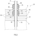
- FIG. 2 is a diagram for explaining the support structure S1 for the pipe P according to First Example.
- FIG. 2 is an enlarged view of portions where the pipe P penetrates the inner tank 3, the intermediate tank 4, and the outer tank 5.
- the pipe P is joined to the inner tank 3, is coupled to the intermediate tank 4 through a second expandable pipe 62, and is coupled to the outer tank 5 through a first expandable pipe 61.
- the pipe P may be inserted into the inner tank 3 without being joined to the inner tank 3.
- the term "joined” denotes that the pipe P and the tank (the inner tank 3, the intermediate tank 4, or the outer tank 5) are mechanically or metallurgically coupled to each other without an expandable pipe located therebetween.
- the term “coupled” denotes that the pipe P and the tank (the inner tank 3, the intermediate tank 4, or the outer tank 5) are connected to each other, and the expression “coupled to each other through an expandable pipe” denotes that the pipe P and the tank are connected to each other by the expandable pipe located therebetween.
- the inner tank 3 includes an inner tank insertion hole 34 for the pipe P, and the pipe P is inserted into the inner tank insertion hole 34.
- An opening edge of the inner tank insertion hole 34 and the pipe P are welded to each other to secure airtightness. More specifically, the opening edge of the inner tank insertion hole 34 and the exterior pipe of the pipe P are welded to each other to secure the airtightness.
- This welded portion can be substantially regarded as a joined portion 73 where the inner tank 3 and the pipe P are joined to each other.
- the intermediate tank 4 includes an intermediate tank insertion hole 44 for the pipe P, and the pipe P is inserted into the intermediate tank insertion hole 44.
- the second expandable pipe 62 is joined to an opening edge of the intermediate tank insertion hole 44.
- the second expandable pipe 62 is a tubular member projecting outward (i.e., toward the outer tank 5) from the intermediate tank 4, and the pipe P is inserted into the second expandable pipe 62.
- a fibrous insulation 69 such as glass wool, is filled in between an outer peripheral surface of the pipe P and an inner peripheral surface of the second expandable pipe 62.
- a base portion of the second expandable pipe 62 is joined to the intermediate tank 4, and a tip portion of the second expandable pipe 62 is joined to the pipe P.
- a joined portion where the second expandable pipe 62 and the intermediate tank 4 are joined to each other and a joined portion where the second expandable pipe 62 and the pipe P are joined to each other may be welded to secure the airtightness.
- the joined portion where the tip portion of the second expandable pipe 62 and the pipe P are joined to each other can be substantially regarded as a joined portion 65 where the intermediate tank 4 and the pipe P are joined to each other.
- At least part of the second expandable pipe 62 includes an expandable portion 64.
- the expandable portion 64 may be realized by, for example, a corrugation or a bellows which is located at a middle portion of the second expandable pipe 62.
- the tip portion of the second expandable pipe 62 is allowed to be displaced relative to the base portion of the second expandable pipe 62 in both of a radial direction and axial direction of the second expandable pipe 62.
- the joined portion 65 is allowed to be displaced relative to a main body of the intermediate tank 4.
- the outer tank 5 includes an outer tank insertion hole 54 for the pipe P, and the pipe P is inserted into the outer tank insertion hole 54.
- the first expandable pipe 61 is joined to an opening edge of the outer tank insertion hole 54.
- the first expandable pipe 61 is a tubular member projecting outward from the outer tank 5, and the pipe P is inserted into the first expandable pipe 61.
- a fibrous insulation 70 such as glass wool, is filled in between the outer peripheral surface of the pipe P and an inner peripheral surface of the first expandable pipe 61.
- a base portion of the first expandable pipe 61 is joined to the outer tank 5, and a tip portion of the first expandable pipe 61 is joined to the pipe P.
- a joined portion where the first expandable pipe 61 and the outer tank 5 are joined to each other and a joined portion where the first expandable pipe 61 and the pipe P are joined to each other may be welded to secure the airtightness.
- the joined portion where the tip portion of the first expandable pipe 61 and the pipe P are joined to each other can be substantially regarded as a joined portion 66 where the outer tank 5 and the pipe P are joined to each other.
- At least part of the first expandable pipe 61 includes an expandable portion 63.
- the expandable portion 63 may be realized by, for example, a corrugation or a bellows which is located at a middle portion of the first expandable pipe 61.
- the tip portion of the first expandable pipe 61 is allowed to be displaced relative to the base portion of the first expandable pipe 61 in both of a radial direction and axial direction of the first expandable pipe 61.
- the joined portion 66 is allowed to be displaced relative to a main body of the outer tank 5.
- an inter-tank distance of the first inter-tank region 91 i.e., an interval between the inner tank 3 and the intermediate tank 4
- an inter-tank distance of the second inter-tank region 92 i.e., an interval between the intermediate tank 4 and the outer tank 5
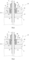
- a powder leakage prevention dike 67 may be located around the second expandable pipe 62 located at the intermediate tank 4 in the support structure S 1 for the pipe P according to First Example.
- the powder leakage prevention dike 67 is located in the second inter-tank region 92 and prevents the powdered insulation from flowing into a region around the second expandable pipe 62.
- the powder leakage prevention dike 67 is a cylindrical member surrounding the second expandable pipe 62.
- the powder leakage prevention dike 67 is made of, for example, polyurethane foam.
- One end portion of the powder leakage prevention dike 67 is joined to a surface of the intermediate tank 4 by adhesion.
- a region between the powder leakage prevention dike 67 and the second expandable pipe 62 may be a space, but it is desirable that a fibrous insulation 72, such as glass wool, be filled in the region.
- the powder leakage prevention dike 67 is not limited to the configuration shown in FIG. 3 as long as the powder leakage prevention dike 67 can prevent the powdered insulation from entering into the region around the second expandable pipe 62.
- the powder leakage prevention dike 67 may be a tubular member surrounding the second expandable pipe 62 and including both end portions which are not j oined to the pipe P and the intermediate tank 4.
- the powder leakage prevention dike 67 may be a tubular member surrounding the second expandable pipe 62 and may be joined to the pipe P.
- the region between the powder leakage prevention dike 67 and the second expandable pipe 62 may be a space, but it is desirable that the fibrous insulation 72, such as glass wool, be filled in the region.
- the second expandable pipe 62 projects outward from the intermediate tank 4.
- the second expandable pipe 62 may project inward from the intermediate tank 4.
- the second expandable pipe 62 is a tubular member that exists in the first inter-tank region 91 and surrounds the pipe P.
- the base portion of the second expandable pipe 62 is joined to the intermediate tank 4, and the tip portion of the second expandable pipe 62 is joined to the pipe P.
- the powder leakage prevention dike 67 be located around the second expandable pipe 62 in order that the powdered insulation filled in the first inter-tank region 91 is prevented from flowing into the region around the second expandable pipe 62.
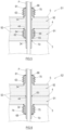
- FIG. 6 is a diagram for explaining the support structure S2 for the pipe P according to Second Example.
- FIG. 6 is an enlarged view of portions where the pipe P penetrates the inner tank 3, the intermediate tank 4, and the outer tank 5.
- the pipe P is joined to the intermediate tank 4, is coupled to the inner tank 3 through a second expandable pipe 68, and is coupled to the outer tank 5 through the first expandable pipe 61. Since a coupling structure in which the outer tank 5 and the pipe P are coupled to each other through the first expandable pipe 61 is substantially the same as that in the support structure S1 for the pipe P according to First Example, a detailed explanation thereof is omitted.
- the intermediate tank 4 includes the intermediate tank insertion hole 44 for the pipe P, and the pipe P is inserted into the intermediate tank insertion hole 44.
- the opening edge of the intermediate tank insertion hole 44 and the pipe P are welded to each other to secure the airtightness. More specifically, the opening edge of the intermediate tank insertion hole 44 and the exterior pipe of the pipe P are welded to each other to secure the airtightness.
- This welded portion can be substantially regarded as the joined portion 65 where the intermediate tank 4 and the pipe P are joined to each other.
- the pipe P is inserted into the intermediate tank insertion hole 44, but the pipe P and the intermediate tank insertion hole 44 do not have to be joined to each other.
- the inner tank 3 includes the inner tank insertion hole 34 for the pipe P, and the pipe P is inserted into the inner tank insertion hole 34.
- the second expandable pipe 68 is joined to the opening edge of the inner tank insertion hole 34.
- the second expandable pipe 68 is a tubular member projecting inward (i.e., toward the inside of the tank) from the inner tank 3, and the pipe P is inserted into the second expandable pipe 68.
- a fibrous insulation 75 such as glass wool, is filled in between the outer peripheral surface of the pipe P and an inner peripheral surface of the second expandable pipe 68.
- a base portion of the second expandable pipe 68 is joined to the inner tank 3, and a tip portion of the second expandable pipe 68 is joined to the pipe P.
- a joined portion where the second expandable pipe 68 and the inner tank 3 are joined to each other and a joined portion where the expandable pipe 68 and the pipe P are joined to each other may be welded to secure the airtightness.
- the joined portion where the tip portion of the expandable pipe 68 and the pipe P are joined to each other can be substantially regarded as the joined portion 73 where the inner tank 3 and the pipe P are joined to each other.
- At least part of the second expandable pipe 68 includes an expandable portion 74.
- the expandable portion 74 may be realized by, for example, a corrugation or a bellows which is located at a middle portion of the second expandable pipe 68.
- the tip portion of the second expandable pipe 68 is allowed to be displaced relative to the base portion of the second expandable pipe 68 in both of a radial direction and axial direction of the second expandable pipe 68.
- the joined portion 73 is allowed to be displaced relative to a main body of the inner tank 3.
- the inter-tank distance of the first inter-tank region 91 and the inter-tank distance of the second inter-tank region 92 change from those when the inner tank 3 is empty.
- the second expandable pipe 68 projects inward from the inner tank 3. Therefore, even when the first inter-tank region 91 is narrow, the second expandable pipe 68 can be located at the inner tank 3. However, the expandable pipe 68 may project outward from the inner tank 3 and may be located in the first inter-tank region 91.
- FIG. 7 is a diagram for explaining the support structure S3 for the pipe P according to Third Example.
- FIG. 7 is an enlarged view of portions where the pipe P penetrates the inner tank 3, the intermediate tank 4, and the outer tank 5.
- the support structure S3 for the pipe P according to Third Example is especially applied to a pipe (such as the BOG pipe 22) that penetrates a roof of the triple containment tank 1.
- the pipe P is joined to the intermediate tank 4, is coupled to the outer tank 5 through the first expandable pipe 61, and is not joined to the inner tank 3. Since the coupling structure in which the outer tank 5 and the pipe P are coupled to each other through the first expandable pipe 61 is substantially the same as that in the support structure S1 for the pipe P according to First Example, a detailed explanation thereof is omitted. Moreover, since a joined structure in which the intermediate tank 4 and the pipe P are joined to each other is substantially the same as that in the support structure S2 for the pipe P according to Second Example, a detailed explanation thereof is omitted.
- the inner tank 3 includes the inner tank insertion hole 34 for the pipe P, and the pipe P is loosely inserted into the inner tank insertion hole 34.
- the inside of the inner tank 3 and the first inter-tank region 91 between the inner tank 3 and the intermediate tank 4 communicate with each other through a gap between the opening edge of the inner tank insertion hole 34 and the pipe P.
- a boil off gas in the inner tank 3 flows into the first inter-tank region 91. Therefore, when the support structure S3 for the pipe P is adopted, the communication pipe 21 may be omitted.
- the insulation 93 such as a fibrous insulation, a panel insulation, or a block insulation, which does not have flowability, be located around the inner tank insertion hole 34.
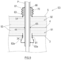
- the inside of the inner tank 3 and the first inter-tank region 91 may be physically isolated from each other such that the insulation 93, dust, and the like are prevented from getting into the inside of the inner tank 3 through the gap between the inner tank insertion hole 34 and the pipe P. For example, as shown in FIG.
- a tubular body 81 is inserted into the inner tank insertion hole 34 so as to be substantially concentric with the pipe P, and an outer wall of the tubular body 81 and an edge of the inner tank insertion hole 34 are fixed to each other.
- the tubular body 81 projects from a wall of the inner tank 3 to both of the inside of the first inter-tank region 91 and the inside of the inner tank 3.
- a flange-shaped cover plate 83 projecting from the outer wall of the pipe P in the radial direction is fixed to the pipe P.
- the cover plate 83 covers a gap between an end portion of the tubular body 81 and the pipe P and is located away from the tubular body 81 so as not to interfere with the tubular body 81.
- An outer edge of the cover plate 83 and an upper end of the tubular body 81 are connected to each other by a filter 82.
- a gap between the cover plate 83 and the tubular body 81 is closed by the filter 82 such that gas is allowed to flow through the gap.
- the filter 82 is made of a material that can expand, contract, and be deformed, or the filter 82 has an expansion/contraction margin, the filter 82 is deformed so as to follow a change in size of the gap. It is desirable that the filter 82 be made of a material, such as glass cloth, which is thermally and chemically stable.
- the cover plate 83 and the filter 82 are located in the first inter-tank region 91. However, as shown in FIG. 9 , the cover plate 83 and the filter 82 may be located in the inner tank 3.
- the cover plate 83 projecting from the outer wall of the pipe P in the radial direction is fixed to the pipe P, and the outer edge of the cover plate 83 and a lower end of the tubular body 81 are connected to each other by the filter 82.
- the inter-tank distance of the first inter-tank region 91 and the inter-tank distance of the second inter-tank region 92 change from those when the inner tank 3 is empty. Even when the inter-tank distance of the second inter-tank region 92 changes as above, such change is absorbed by the expansion and contraction of the first expandable pipe 61, and this reduces stress generated at the joined portion 65 where the intermediate tank 4 and the pipe P are joined to each other and the joined portion 66 where the outer tank 5 and the pipe P are joined to each other. Moreover, the pipe P is not joined to the inner tank 3.
- the communication pipe 21 can be omitted.
- the triple containment tank 1 according to the present embodiment including the support structure S1 or S2 for the pipe P according to First or Second Example includes:
- the triple containment tank 1 configured as above, when the low temperature liquefied gas is stored in the inner tank 3, and therefore, the inter-tank distances of the inner tank 3, the intermediate tank 4, and the outer tank 5 change due to the thermal contraction of the tanks, the changes of the inter-tank distances are absorbed by the expansion and contraction of the expandable pipes 61, 62, and 68, and this reduces the stress generated at the joined portions 73, 65, and 66 where the respective tanks and the pipe P are joined to each other.
- the support structures S1 and S2 for the pipe P each of which is included in the triple containment tank 1 configured as above is suitable for supporting the pipe P penetrating the triple shell of the triple containment tank 1 including the triple shell including the inner tank 3, the intermediate tank 4, and the outer tank 5.
- the intermediate tank 4 includes the intermediate tank insertion hole 44 into which the pipe P is inserted, the base portion of the second expandable pipe 62 is joined to the intermediate tank 4 so as to project outward from the edge of the intermediate tank insertion hole 44, and the tip portion of the second expandable pipe 62 is joined to the pipe P.
- the second expandable pipe 62 is located in the second inter-tank region 92. Therefore, as compared to a case where the second expandable pipe 62 is located in the inner tank 3 or in the first inter-tank region 91, construction is easy, and the degree of cold heat resistance of the second expandable pipe 62 may be low.
- the powdered insulation may be filled in the second inter-tank region 92 between the intermediate tank 4 and the outer tank 5, and the powder leakage prevention dike 67 that prevents the powdered insulation from moving to the region around the second expandable pipe 62 may be located around the second expandable pipe 62.
- the fibrous insulation 72 may be filled in a gap between the powder leakage prevention dike 67 and the pipe P in the radial direction of the pipe P.
- the powder leakage prevention dike 67 may be a tubular member surrounding the second expandable pipe 62, a first end portion of the tubular member and the intermediate tank 4 may be joined to each other, and a second end portion of the tubular member and the pipe P may be joined to each other.
- the intermediate tank 4 includes the intermediate tank insertion hole 44 into which the pipe P is inserted.
- the base portion of the second expandable pipe 62 is joined to the intermediate tank 4 so as to project inward from the edge of the intermediate tank insertion hole 44, and the tip portion of the second expandable pipe 62 is joined to the pipe P.
- the powdered insulation is filled in the first inter-tank region 91 between the inner tank 3 and the intermediate tank 4, and the powder leakage prevention dike 67 that prevents the powdered insulation from moving to the region around the second expandable pipe 62 is located around the second expandable pipe 62.
- the fibrous insulation 72 may be filled in the gap between the powder leakage prevention dike 67 and the pipe P in the radial direction of the pipe P.
- the powder leakage prevention dike 67 may be a tubular member surrounding the second expandable pipe 62, the first end portion of the tubular member and the intermediate tank 4 may be joined to each other, and the second end portion of the tubular member and the pipe P may be joined to each other.
- the powder leakage prevention dike 67 When the powder leakage prevention dike 67 is located around the second expandable pipe 62 as above, the powdered insulation is prevented from being clogged in the expandable portion 64 of the second expandable pipe 62, and the powdered insulation is prevented from being welded with pressure to the expandable portion 64 of the second expandable pipe 62. Therefore, the expansion, contraction, and shear deformation of the second expandable pipe 62 are not inhibited.
- the inner tank 3 includes the inner tank insertion hole 34 into which the pipe P is inserted.
- the base portion of the second expandable pipe 68 is joined to the inner tank 3 so as to project inward from the edge of the inner tank insertion hole 34, and the tip portion of the second expandable pipe 68 is joined to the pipe P.
- the second expandable pipe 68 projects to the inside of the inner tank 3, there are few constraints regarding an installation space for the second expandable pipe 68, and the degrees of freedom of the design and the construction are high.
- triple containment tank 1 including the support structure S3 for the pipe P according to Third Example includes:
- the triple containment tank 1 configured as above, when the low temperature liquefied gas is stored in the inner tank 3, and therefore, the inter-tank distances of the inner tank 3, the intermediate tank 4, and the outer tank 5 change due to the thermal contraction, the changes of the inter-tank distances are absorbed by the expansion and contraction of the first expandable pipe 61, and this reduces the stress generated at the joined portion 65 where the intermediate tank 4 and the pipe P are joined to each other and the joined portion 66 where the outer tank 5 and the pipe P are joined to each other.
- the support structure S3 for the pipe P which is included in the triple containment tank 1 configured as above is suitable for supporting the pipe P penetrating the triple shell of the triple containment tank 1 including the triple shell including the inner tank 3, the intermediate tank 4, and the outer tank 5.
- the communication pipe 21 can be omitted.
- the triple containment tank 1 including the support structure S3 for the pipe P according to Third Example may further include: the tubular body 81 which is fixed to the edge of the inner tank insertion hole 34 and into which the pipe P is loosely inserted; the flange-shaped cover plate 83 located away from the tubular body 81 in the first inter-tank region 91 or the inner tank 3 and projecting from the outer wall of the pipe P in the radial direction; and the expandable filter 82 which closes the gap between the tubular body 81 and the cover plate 83 such that gas is allowed to flow through the gap.
- gas is allowed to pass through between the inner tank insertion hole 34 and the pipe P, and solids, such as a cold insulation and powder dust, are prevented from passing through between the inner tank insertion hole 34 and the pipe P. Since the gas in the inner tank 3 can move to the first inter-tank region 91 through the inner tank insertion hole 34, the communication pipe 21 can be omitted. Moreover, the flow of the gas from the inner tank 3 through the inner tank insertion hole 34 to the first inter-tank region 91 can be prevented from directly colliding with the intermediate tank 4.
- the inner tank 3, the intermediate tank 4, and the outer tank 5 are cylindrical flat-bottomed tanks, but the shapes of these tanks are not limited to cylindrical shapes.
- the inner tank 3, the intermediate tank 4, and the outer tank 5 may be substantially polygonal tubular flat-bottomed tanks.
- each of the inner tank 3, the intermediate tank 4, and the outer tank 5 may have airtightness.
- the triple containment tank 1 is located on land.
- the support structures S1-S3 for the pipe P in the triple containment tank 1 may be applied to triple containment tanks mounted on ships.
Landscapes
- Engineering & Computer Science (AREA)
- Mechanical Engineering (AREA)
- General Engineering & Computer Science (AREA)
- Physics & Mathematics (AREA)
- Thermal Sciences (AREA)
- Filling Or Discharging Of Gas Storage Vessels (AREA)
- Apparatus Associated With Microorganisms And Enzymes (AREA)
Abstract
Description
- The present disclosure relates to a triple containment tank that stores a low temperature liquefied gas, particularly to a support structure for a nozzle that penetrates a triple shell.
- Double-shell tanks that store a low temperature liquefied gas have been known. Typically, the double-shell tank includes: a double shell including an inner tank and an outer tank; and an insulation filled in between the inner tank and the outer tank. The double-shell tank includes a pipe through which a low temperature liquid stored in the inner tank is discharged to an outside of the tank. Such pipe penetrates both of the inner tank and the outer tank.
- According to the double-shell tank, when the low temperature liquefied gas is stored in the inner tank, the inner tank contracts by cold heat of the low temperature liquefied gas. Therefore, the inner tank and the outer tank are displaced relative to each other. Since each tank stores a liquid and/or a gas, airtightness between each tank and the pipe is required. However, when the pipe is directly coupled to both of the inner tank and the outer tank to secure the airtightness, excessive stress acts on the coupled portions by the relative displacement between the inner tank and the outer tank. Each of
PTLs - According to a low temperature tank (double-shell tank) of
PTL 1, a nozzle for liquid injection and discharge penetrates a roof of the inner tank and a roof of the outer tank. The nozzle is supported by the roof of the outer tank by being suspended from the roof of the outer tank and is hermetically coupled to the roof of the inner tank through a bellows. - According to a low temperature tank (double-shell tank) of
PTL 2, a liquid delivering nozzle penetrates a roof of the inner tank and a roof of the outer tank, and an outer barrel of the nozzle is coupled to a portion of the roof of the inner tank which is lower in rigidity than the other portion of the roof of the inner tank. The roof of the outer tank and the outer barrel are coupled to each other through a bellows, and the outer barrel is mounted on a support base located at a bottom plate of the inner tank. -
- PTL 1:
Japanese Laid-Open Patent Application Publication No. 58-17296 - PTL 2:
Japanese Laid-Open Utility Model Application Publication No. 58-14594 - Triple containment tanks in which an intermediate tank is further added between the inner tank and outer tank of the double-shell tank are also known. According to the triple containment tank, when a low temperature liquefied gas is stored in the inner tank, inter-tank distances of the inner tank, the intermediate tank, and the outer tank change by thermal contraction. Since the temperatures of the inner tank, the intermediate tank, and the outer tank are different from each other, the degrees of change of the inter-tank distances of the respective tanks are also different from each other. Each of
PTLs PTLs PTLs - The present disclosure was made under these circumstances, and an object of the present disclosure is to propose, in a triple containment tank including a triple shell including an inner tank, an intermediate tank, and an outer tank, a support structure for a pipe penetrating the triple shell.
- A triple containment tank according to one aspect of the present disclosure includes:
- an outer tank;
- an intermediate tank located in the outer tank;
- an inner tank located in the intermediate tank and storing a liquefied gas therein; and
- a pipe penetrating the outer tank, the intermediate tank, and the inner tank, wherein
- the pipe is coupled to the outer tank through a first expandable pipe, is coupled to one of the inner tank and the intermediate tank through a second expandable pipe, and is joined to or inserted into the other of the inner tank and the intermediate tank.
- Moreover, a triple containment tank according to another aspect of the present disclosure includes:
- an outer tank;
- an intermediate tank located in the outer tank;
- an inner tank which is located in the intermediate tank, includes an inner tank insertion hole, and stores a liquefied gas therein; and
- a pipe penetrating the outer tank, the intermediate tank, and the inner tank, wherein:
- the pipe and the outer tank are coupled to each other through a first expandable pipe;
- the pipe and the intermediate tank are joined to each other;
- the pipe is loosely inserted into the inner tank insertion hole; and
- an inside of the inner tank and an inter-tank region between the inner tank and the intermediate tank communicate with each other through a gap between the inner tank insertion hole and the pipe.
- According to the triple containment tank configured as above, when the low temperature liquefied gas is stored in the inner tank, and therefore, the inter-tank distances of the inner tank, the intermediate tank, and the outer tank change due to the thermal contraction of the tanks, the changes of the inter-tank distances are absorbed by the expansion and contraction of the expandable pipes, and this reduces the stress generated at joined portions where the respective tanks and the pipe are joined to each other. Therefore, the support structure for the pipe which is included in the triple containment tank configured as above is a structure suitable for supporting the pipe penetrating the triple shell of the triple containment tank including the triple shell including the inner tank, the intermediate tank, and the outer tank.
- The present disclosure can propose, in a triple containment tank including a triple shell including an inner tank, an intermediate tank, and an outer tank, a support structure for a pipe penetrating the triple shell.
-
-
FIG. 1 is a sectional view showing an entire configuration of a triple containment tank according to an embodiment of the present disclosure. -
FIG. 2 is a diagram for explaining a support structure for a pipe according to First Example. -
FIG. 3 is a diagram for explaining the support structure for the pipe according to Modified Example 1 of First Example. -
FIG. 4 is a diagram for explaining the support structure for the pipe according to Modified Example 2 of First Example. -
FIG. 5 is a diagram for explaining the support structure for the pipe according to Modified Example 3 of First Example. -
FIG. 6 is a diagram for explaining the support structure for the pipe according to Second Example. -
FIG. 7 is a diagram for explaining the support structure for the pipe according to Third Example. -
FIG. 8 is a diagram for explaining the support structure for the pipe according to Modified Example 1 of Third Example. -
FIG. 9 is a diagram for explaining the support structure for the pipe according to Modified Example 2 of Third Example. - An embodiment of the present disclosure will be described with reference to the drawings.
FIG. 1 is a sectional view showing an entire configuration of atriple containment tank 1 according to the embodiment of the present disclosure. - The
triple containment tank 1 shown inFIG. 1 is a stationary flat-bottomed triple containment tank placed on the ground. Thetriple containment tank 1 includes: atank foundation 7 made of concrete; anouter tank 5 located on thetank foundation 7; anintermediate tank 4 located inside theouter tank 5; and aninner tank 3 located inside theintermediate tank 4. Theouter tank 5, theintermediate tank 4, and theinner tank 3 form a triple shell. - The
inner tank 3 is a container that stores a low temperature liquefied gas. Examples of the low temperature liquefied gas include liquid helium, liquid hydrogen, liquid nitrogen, LNG, and LPG. Theinner tank 3 includes: a substantially flat innertank bottom plate 31; a cylindrical innertank side plate 32 standing from the innertank bottom plate 31; and aninner tank roof 33 located at an upper portion of the innertank side plate 32. The innertank side plate 32 and thetank foundation 7 may be coupled to each other by, for example, mooring members, such as anchor straps, located around theinner tank 3 at substantially regular intervals. - The
intermediate tank 4 surrounds theinner tank 3. Theintermediate tank 4 includes: a substantially flat intermediatetank bottom plate 41; a cylindrical intermediatetank side plate 42 standing from the intermediatetank bottom plate 41; and anintermediate tank roof 43 located at an upper portion of the intermediatetank side plate 42. Alevel concrete layer 35 and an innerbottom insulation layer 36 are located between the intermediatetank bottom plate 41 and the innertank bottom plate 31 in an upper-lower direction. Theintermediate tank roof 43 may support theinner tank roof 33. To be specific, theinner tank roof 33 may be a suspended roof. The intermediatetank side plate 42 and thetank foundation 7 may be coupled to each other by, for example, mooring members, such as anchor straps, located around theintermediate tank 4 at substantially regular intervals. - The
outer tank 5 surrounds theintermediate tank 4. Theouter tank 5 includes: a substantially flat outertank bottom plate 51 located on thetank foundation 7; a cylindrical outertank side plate 52 standing from the outertank bottom plate 51; and anouter tank roof 53 located at an upper portion of the outertank side plate 52. Alevel concrete layer 45 and an outerbottom insulation layer 46 are located between the outertank bottom plate 51 and the intermediatetank bottom plate 41 in the upper-lower direction. The outertank side plate 52 may be coupled to thetank foundation 7 by, for example, coupling members, such as anchor bolts. Or, the outertank bottom plate 51 may be coupled to thetank foundation 7 by, for example, coupling members, such as anchor plates driven in thetank foundation 7. - There is a gap between an outer wall of the
inner tank 3 and an inner wall of theintermediate tank 4, i.e., a firstinter-tank region 91 is located therebetween. There is a gap between an outer wall of theintermediate tank 4 and an inner wall of theouter tank 5, i.e., a secondinter-tank region 92 is located therebetween. The firstinter-tank region 91 and the secondinter-tank region 92 are filled with aninsulation 93. For example, theinsulation 93 may be perlite, glass wool, or the like which has been used as an insulation of a double-shell tank. - A
BOG pipe 22 is open at theinner tank roof 33. A vaporized gas generated in theinner tank 3 is sent through theBOG pipe 22 to an outside of thetriple containment tank 1. A deliveringpipe 25 is open at a lower portion of theinner tank 3. The liquefied gas in theinner tank 3 is sent through the deliveringpipe 25 to the outside. However, the deliveringpipe 25 may extend upward in theinner tank 3 and send the liquefied gas to the outside through an upper portion of thetriple containment tank 1. Acommunication pipe 21 through which an upper portion in theinner tank 3 and the firstinter-tank region 91 communicate with each other is located at theinner tank roof 33 of theinner tank 3. The vaporized gas of the liquefied gas which is generated in theinner tank 3 flows into the firstinter-tank region 91 through thecommunication pipe 21. Thus, the firstinter-tank region 91 is filled with the vaporized gas of the liquefied gas. However, a gas having a low boiling point equal to that of the vaporized gas of the liquefied gas may be introduced into the firstinter-tank region 91 from the outside of thetriple containment tank 1. Or, the vaporized gas of the liquefied gas may be introduced into the firstinter-tank region 91 by connecting a branch pipe of theBOG pipe 22 and the firstinter-tank region 91. - The first
inter-tank region 91 and the secondinter-tank region 92 as spaces are separated from each other by airtightness of theintermediate tank 4 that separates the firstinter-tank region 91 and the secondinter-tank region 92. The secondinter-tank region 92 is supplied with an inert gas from an inertgas supply source 24 through anintroduction pipe 23 and filled with the inert gas. This inert gas is a gas having a higher boiling point than the liquefied gas stored in theinner tank 3. One example of such inert gas is nitrogen. - In the
triple containment tank 1 configured as above, each of theBOG pipe 22 and the deliveringpipe 25 is a pipe which penetrates the triple shell including theinner tank 3, theintermediate tank 4, and theouter tank 5 and through which the inside and outside of theinner tank 3 communicate with each other. The following will describe support structures S1-S3 according to First to Third Examples for a pipe P, such as theBOG pipe 22 or the deliveringpipe 25, which penetrates the triple shell. The support structures S1-S3 for the pipe P are applicable to not only theBOG pipe 22 and the deliveringpipe 25 but also any pipe that penetrates the triple shell. The pipe P described below is a vacuum double pipe including a main pipe and an exterior pipe. However, the pipe P to which the support structures S1-S3 are applied is not limited to the vacuum double pipe. -
FIG. 2 is a diagram for explaining the support structure S1 for the pipe P according to First Example.FIG. 2 is an enlarged view of portions where the pipe P penetrates theinner tank 3, theintermediate tank 4, and theouter tank 5. - According to the support structure S1 for the pipe P in
FIG. 2 , the pipe P is joined to theinner tank 3, is coupled to theintermediate tank 4 through a secondexpandable pipe 62, and is coupled to theouter tank 5 through a firstexpandable pipe 61. The pipe P may be inserted into theinner tank 3 without being joined to theinner tank 3. In the present description, the term "joined" denotes that the pipe P and the tank (theinner tank 3, theintermediate tank 4, or the outer tank 5) are mechanically or metallurgically coupled to each other without an expandable pipe located therebetween. Moreover, in the present description, the term "coupled" denotes that the pipe P and the tank (theinner tank 3, theintermediate tank 4, or the outer tank 5) are connected to each other, and the expression "coupled to each other through an expandable pipe" denotes that the pipe P and the tank are connected to each other by the expandable pipe located therebetween. - The
inner tank 3 includes an innertank insertion hole 34 for the pipe P, and the pipe P is inserted into the innertank insertion hole 34. An opening edge of the innertank insertion hole 34 and the pipe P are welded to each other to secure airtightness. More specifically, the opening edge of the innertank insertion hole 34 and the exterior pipe of the pipe P are welded to each other to secure the airtightness. This welded portion can be substantially regarded as a joinedportion 73 where theinner tank 3 and the pipe P are joined to each other. - The
intermediate tank 4 includes an intermediatetank insertion hole 44 for the pipe P, and the pipe P is inserted into the intermediatetank insertion hole 44. The secondexpandable pipe 62 is joined to an opening edge of the intermediatetank insertion hole 44. The secondexpandable pipe 62 is a tubular member projecting outward (i.e., toward the outer tank 5) from theintermediate tank 4, and the pipe P is inserted into the secondexpandable pipe 62. Afibrous insulation 69, such as glass wool, is filled in between an outer peripheral surface of the pipe P and an inner peripheral surface of the secondexpandable pipe 62. - A base portion of the second
expandable pipe 62 is joined to theintermediate tank 4, and a tip portion of the secondexpandable pipe 62 is joined to the pipe P. A joined portion where the secondexpandable pipe 62 and theintermediate tank 4 are joined to each other and a joined portion where the secondexpandable pipe 62 and the pipe P are joined to each other may be welded to secure the airtightness. The joined portion where the tip portion of the secondexpandable pipe 62 and the pipe P are joined to each other can be substantially regarded as a joinedportion 65 where theintermediate tank 4 and the pipe P are joined to each other. - At least part of the second
expandable pipe 62 includes anexpandable portion 64. Theexpandable portion 64 may be realized by, for example, a corrugation or a bellows which is located at a middle portion of the secondexpandable pipe 62. By theexpandable portion 64, the tip portion of the secondexpandable pipe 62 is allowed to be displaced relative to the base portion of the secondexpandable pipe 62 in both of a radial direction and axial direction of the secondexpandable pipe 62. In other words, the joinedportion 65 is allowed to be displaced relative to a main body of theintermediate tank 4. - The
outer tank 5 includes an outertank insertion hole 54 for the pipe P, and the pipe P is inserted into the outertank insertion hole 54. The firstexpandable pipe 61 is joined to an opening edge of the outertank insertion hole 54. The firstexpandable pipe 61 is a tubular member projecting outward from theouter tank 5, and the pipe P is inserted into the firstexpandable pipe 61. Afibrous insulation 70, such as glass wool, is filled in between the outer peripheral surface of the pipe P and an inner peripheral surface of the firstexpandable pipe 61. - A base portion of the first
expandable pipe 61 is joined to theouter tank 5, and a tip portion of the firstexpandable pipe 61 is joined to the pipe P. A joined portion where the firstexpandable pipe 61 and theouter tank 5 are joined to each other and a joined portion where the firstexpandable pipe 61 and the pipe P are joined to each other may be welded to secure the airtightness. The joined portion where the tip portion of the firstexpandable pipe 61 and the pipe P are joined to each other can be substantially regarded as a joinedportion 66 where theouter tank 5 and the pipe P are joined to each other. - At least part of the first
expandable pipe 61 includes anexpandable portion 63. Theexpandable portion 63 may be realized by, for example, a corrugation or a bellows which is located at a middle portion of the firstexpandable pipe 61. By theexpandable portion 63, the tip portion of the firstexpandable pipe 61 is allowed to be displaced relative to the base portion of the firstexpandable pipe 61 in both of a radial direction and axial direction of the firstexpandable pipe 61. In other words, the joinedportion 66 is allowed to be displaced relative to a main body of theouter tank 5. - According to the
triple containment tank 1 including the support structure S1, when the low temperature liquefied gas is stored in theinner tank 3, an inter-tank distance of the first inter-tank region 91 (i.e., an interval between theinner tank 3 and the intermediate tank 4) and an inter-tank distance of the second inter-tank region 92 (i.e., an interval between theintermediate tank 4 and the outer tank 5) change from those when theinner tank 3 is empty. Even when the inter-tank distance of the firstinter-tank region 91 and the inter-tank distance of the secondinter-tank region 92 change as above, such changes are absorbed by the expansion and contraction of theexpandable pipes portion 73 where theinner tank 3 and the pipe P are joined to each other, the joinedportion 65 where theintermediate tank 4 and the pipe P are joined to each other, and the joinedportion 66 where theouter tank 5 and the pipe P are joined to each other. - As shown in
FIG. 3 , when a powdered insulation as theinsulation 93 is filled in between theinner tank 3 and theintermediate tank 4, a powderleakage prevention dike 67 may be located around the secondexpandable pipe 62 located at theintermediate tank 4 in thesupport structure S 1 for the pipe P according to First Example. The powderleakage prevention dike 67 is located in the secondinter-tank region 92 and prevents the powdered insulation from flowing into a region around the secondexpandable pipe 62. - In the example shown in
FIG. 3 , the powderleakage prevention dike 67 is a cylindrical member surrounding the secondexpandable pipe 62. The powderleakage prevention dike 67 is made of, for example, polyurethane foam. One end portion of the powderleakage prevention dike 67 is joined to a surface of theintermediate tank 4 by adhesion. A region between the powderleakage prevention dike 67 and the secondexpandable pipe 62 may be a space, but it is desirable that afibrous insulation 72, such as glass wool, be filled in the region. - The powder
leakage prevention dike 67 is not limited to the configuration shown inFIG. 3 as long as the powderleakage prevention dike 67 can prevent the powdered insulation from entering into the region around the secondexpandable pipe 62. For example, the powderleakage prevention dike 67 may be a tubular member surrounding the secondexpandable pipe 62 and including both end portions which are not j oined to the pipe P and theintermediate tank 4. Moreover, for example, as shown inFIG. 4 , the powderleakage prevention dike 67 may be a tubular member surrounding the secondexpandable pipe 62 and may be joined to the pipe P. Also in this case, the region between the powderleakage prevention dike 67 and the secondexpandable pipe 62 may be a space, but it is desirable that thefibrous insulation 72, such as glass wool, be filled in the region. - In the support structure S1 for the pipe P according to First Example, the second
expandable pipe 62 projects outward from theintermediate tank 4. However, the secondexpandable pipe 62 may project inward from theintermediate tank 4. In this case, as shown inFIG. 5 , the secondexpandable pipe 62 is a tubular member that exists in the firstinter-tank region 91 and surrounds the pipe P. The base portion of the secondexpandable pipe 62 is joined to theintermediate tank 4, and the tip portion of the secondexpandable pipe 62 is joined to the pipe P. Even when the secondexpandable pipe 62 projects inward from theintermediate tank 4 as above, it is desirable that as with the above, the powderleakage prevention dike 67 be located around the secondexpandable pipe 62 in order that the powdered insulation filled in the firstinter-tank region 91 is prevented from flowing into the region around the secondexpandable pipe 62. -
FIG. 6 is a diagram for explaining the support structure S2 for the pipe P according to Second Example.FIG. 6 is an enlarged view of portions where the pipe P penetrates theinner tank 3, theintermediate tank 4, and theouter tank 5. - According to the support structure S2 for the pipe P in
FIG. 6 , the pipe P is joined to theintermediate tank 4, is coupled to theinner tank 3 through a secondexpandable pipe 68, and is coupled to theouter tank 5 through the firstexpandable pipe 61. Since a coupling structure in which theouter tank 5 and the pipe P are coupled to each other through the firstexpandable pipe 61 is substantially the same as that in the support structure S1 for the pipe P according to First Example, a detailed explanation thereof is omitted. - The
intermediate tank 4 includes the intermediatetank insertion hole 44 for the pipe P, and the pipe P is inserted into the intermediatetank insertion hole 44. The opening edge of the intermediatetank insertion hole 44 and the pipe P are welded to each other to secure the airtightness. More specifically, the opening edge of the intermediatetank insertion hole 44 and the exterior pipe of the pipe P are welded to each other to secure the airtightness. This welded portion can be substantially regarded as the joinedportion 65 where theintermediate tank 4 and the pipe P are joined to each other. However, when theintermediate tank 4 does not require the airtightness, the pipe P is inserted into the intermediatetank insertion hole 44, but the pipe P and the intermediatetank insertion hole 44 do not have to be joined to each other. - The
inner tank 3 includes the innertank insertion hole 34 for the pipe P, and the pipe P is inserted into the innertank insertion hole 34. The secondexpandable pipe 68 is joined to the opening edge of the innertank insertion hole 34. The secondexpandable pipe 68 is a tubular member projecting inward (i.e., toward the inside of the tank) from theinner tank 3, and the pipe P is inserted into the secondexpandable pipe 68. Afibrous insulation 75, such as glass wool, is filled in between the outer peripheral surface of the pipe P and an inner peripheral surface of the secondexpandable pipe 68. - A base portion of the second
expandable pipe 68 is joined to theinner tank 3, and a tip portion of the secondexpandable pipe 68 is joined to the pipe P. A joined portion where the secondexpandable pipe 68 and theinner tank 3 are joined to each other and a joined portion where theexpandable pipe 68 and the pipe P are joined to each other may be welded to secure the airtightness. The joined portion where the tip portion of theexpandable pipe 68 and the pipe P are joined to each other can be substantially regarded as the joinedportion 73 where theinner tank 3 and the pipe P are joined to each other. - At least part of the second
expandable pipe 68 includes anexpandable portion 74. Theexpandable portion 74 may be realized by, for example, a corrugation or a bellows which is located at a middle portion of the secondexpandable pipe 68. By theexpandable portion 74, the tip portion of the secondexpandable pipe 68 is allowed to be displaced relative to the base portion of the secondexpandable pipe 68 in both of a radial direction and axial direction of the secondexpandable pipe 68. In other words, the joinedportion 73 is allowed to be displaced relative to a main body of theinner tank 3. - According to the
triple containment tank 1 including the support structure S2, when the low temperature liquefied gas is stored in theinner tank 3, the inter-tank distance of the firstinter-tank region 91 and the inter-tank distance of the secondinter-tank region 92 change from those when theinner tank 3 is empty. Even when the inter-tank distance of the firstinter-tank region 91 and the inter-tank distance of the secondinter-tank region 92 change as above, such changes are absorbed by the expansion and contraction of theexpandable pipes portion 73 where theinner tank 3 and the pipe P are joined to each other, the joinedportion 65 where theintermediate tank 4 and the pipe P are joined to each other, and the joinedportion 66 where theouter tank 5 and the pipe P are joined to each other. - In the support structure S2 for the pipe P according to Second Example, the second
expandable pipe 68 projects inward from theinner tank 3. Therefore, even when the firstinter-tank region 91 is narrow, the secondexpandable pipe 68 can be located at theinner tank 3. However, theexpandable pipe 68 may project outward from theinner tank 3 and may be located in the firstinter-tank region 91. -
FIG. 7 is a diagram for explaining the support structure S3 for the pipe P according to Third Example.FIG. 7 is an enlarged view of portions where the pipe P penetrates theinner tank 3, theintermediate tank 4, and theouter tank 5. The support structure S3 for the pipe P according to Third Example is especially applied to a pipe (such as the BOG pipe 22) that penetrates a roof of thetriple containment tank 1. - According to the support structure S3 for the pipe P in
FIG. 7 , the pipe P is joined to theintermediate tank 4, is coupled to theouter tank 5 through the firstexpandable pipe 61, and is not joined to theinner tank 3. Since the coupling structure in which theouter tank 5 and the pipe P are coupled to each other through the firstexpandable pipe 61 is substantially the same as that in the support structure S1 for the pipe P according to First Example, a detailed explanation thereof is omitted. Moreover, since a joined structure in which theintermediate tank 4 and the pipe P are joined to each other is substantially the same as that in the support structure S2 for the pipe P according to Second Example, a detailed explanation thereof is omitted. - The
inner tank 3 includes the innertank insertion hole 34 for the pipe P, and the pipe P is loosely inserted into the innertank insertion hole 34. The inside of theinner tank 3 and the firstinter-tank region 91 between theinner tank 3 and theintermediate tank 4 communicate with each other through a gap between the opening edge of the innertank insertion hole 34 and the pipe P. A boil off gas in theinner tank 3 flows into the firstinter-tank region 91. Therefore, when the support structure S3 for the pipe P is adopted, thecommunication pipe 21 may be omitted. - To prevent the
insulation 93 from entering into the inside of theinner tank 3 through the innertank insertion hole 34, it is desirable that theinsulation 93, such as a fibrous insulation, a panel insulation, or a block insulation, which does not have flowability, be located around the innertank insertion hole 34. However, the inside of theinner tank 3 and the firstinter-tank region 91 may be physically isolated from each other such that theinsulation 93, dust, and the like are prevented from getting into the inside of theinner tank 3 through the gap between the innertank insertion hole 34 and the pipe P. For example, as shown inFIG. 8 , atubular body 81 is inserted into the innertank insertion hole 34 so as to be substantially concentric with the pipe P, and an outer wall of thetubular body 81 and an edge of the innertank insertion hole 34 are fixed to each other. Thetubular body 81 projects from a wall of theinner tank 3 to both of the inside of the firstinter-tank region 91 and the inside of theinner tank 3. In the firstinter-tank region 91, a flange-shapedcover plate 83 projecting from the outer wall of the pipe P in the radial direction is fixed to the pipe P. Thecover plate 83 covers a gap between an end portion of thetubular body 81 and the pipe P and is located away from thetubular body 81 so as not to interfere with thetubular body 81. An outer edge of thecover plate 83 and an upper end of thetubular body 81 are connected to each other by afilter 82. A gap between thecover plate 83 and thetubular body 81 is closed by thefilter 82 such that gas is allowed to flow through the gap. When theinner tank 3 contracts, an interval between thetubular body 81 fixed to theinner tank 3 and thecover plate 83 increases. However, since thefilter 82 is made of a material that can expand, contract, and be deformed, or thefilter 82 has an expansion/contraction margin, thefilter 82 is deformed so as to follow a change in size of the gap. It is desirable that thefilter 82 be made of a material, such as glass cloth, which is thermally and chemically stable. In the example shown inFIG. 8 , thecover plate 83 and thefilter 82 are located in the firstinter-tank region 91. However, as shown inFIG. 9 , thecover plate 83 and thefilter 82 may be located in theinner tank 3. In this case, in theinner tank 3, thecover plate 83 projecting from the outer wall of the pipe P in the radial direction is fixed to the pipe P, and the outer edge of thecover plate 83 and a lower end of thetubular body 81 are connected to each other by thefilter 82. - According to the
triple containment tank 1 including the support structure S3, when the low temperature liquefied gas is stored in theinner tank 3, the inter-tank distance of the firstinter-tank region 91 and the inter-tank distance of the secondinter-tank region 92 change from those when theinner tank 3 is empty. Even when the inter-tank distance of the secondinter-tank region 92 changes as above, such change is absorbed by the expansion and contraction of the firstexpandable pipe 61, and this reduces stress generated at the joinedportion 65 where theintermediate tank 4 and the pipe P are joined to each other and the joinedportion 66 where theouter tank 5 and the pipe P are joined to each other. Moreover, the pipe P is not joined to theinner tank 3. Therefore, even when the inter-tank distance of the firstinter-tank region 91 changes, the stress generated at the joinedportion 65 where theintermediate tank 4 and the pipe P are joined to each other and the stress generated at the joinedportion 66 where theouter tank 5 and the pipe P are joined to each other are reduced. In addition, thecommunication pipe 21 can be omitted. - As described above, the
triple containment tank 1 according to the present embodiment including the support structure S1 or S2 for the pipe P according to First or Second Example includes: - the
outer tank 5; - the
intermediate tank 4 located in theouter tank 5; - the
inner tank 3 located in theintermediate tank 4 and storing the liquefied gas therein; and - the pipe P penetrating the
outer tank 5, theintermediate tank 4, and theinner tank 3, wherein - the pipe P and the
outer tank 5 are coupled to each other through the firstexpandable pipe 61, the pipe P and one of theinner tank 3 and theintermediate tank 4 are coupled to each other through the secondexpandable pipe inner tank 3 and theintermediate tank 4 are joined to each other (or the pipe P is inserted into the other of theinner tank 3 and the intermediate tank 4). - According to the
triple containment tank 1 configured as above, when the low temperature liquefied gas is stored in theinner tank 3, and therefore, the inter-tank distances of theinner tank 3, theintermediate tank 4, and theouter tank 5 change due to the thermal contraction of the tanks, the changes of the inter-tank distances are absorbed by the expansion and contraction of theexpandable pipes portions triple containment tank 1 configured as above is suitable for supporting the pipe P penetrating the triple shell of thetriple containment tank 1 including the triple shell including theinner tank 3, theintermediate tank 4, and theouter tank 5. - In the
triple containment tank 1 including the support structure S1 for the pipe P according to First Example, theintermediate tank 4 includes the intermediatetank insertion hole 44 into which the pipe P is inserted, the base portion of the secondexpandable pipe 62 is joined to theintermediate tank 4 so as to project outward from the edge of the intermediatetank insertion hole 44, and the tip portion of the secondexpandable pipe 62 is joined to the pipe P. According to thetriple containment tank 1 including the support structure S1 for the pipe P, the secondexpandable pipe 62 is located in the secondinter-tank region 92. Therefore, as compared to a case where the secondexpandable pipe 62 is located in theinner tank 3 or in the firstinter-tank region 91, construction is easy, and the degree of cold heat resistance of the secondexpandable pipe 62 may be low. - In the
triple containment tank 1 including the support structure S1 for the pipe P according to First Example, the powdered insulation may be filled in the secondinter-tank region 92 between theintermediate tank 4 and theouter tank 5, and the powderleakage prevention dike 67 that prevents the powdered insulation from moving to the region around the secondexpandable pipe 62 may be located around the secondexpandable pipe 62. Herein, thefibrous insulation 72 may be filled in a gap between the powderleakage prevention dike 67 and the pipe P in the radial direction of the pipe P. Moreover, the powderleakage prevention dike 67 may be a tubular member surrounding the secondexpandable pipe 62, a first end portion of the tubular member and theintermediate tank 4 may be joined to each other, and a second end portion of the tubular member and the pipe P may be joined to each other. - Moreover, in the
triple containment tank 1 including the support structure S1 for the pipe P according to First Example, theintermediate tank 4 includes the intermediatetank insertion hole 44 into which the pipe P is inserted. The base portion of the secondexpandable pipe 62 is joined to theintermediate tank 4 so as to project inward from the edge of the intermediatetank insertion hole 44, and the tip portion of the secondexpandable pipe 62 is joined to the pipe P. According to thetriple containment tank 1 including the support structure S1 for the pipe P, the powdered insulation is filled in the firstinter-tank region 91 between theinner tank 3 and theintermediate tank 4, and the powderleakage prevention dike 67 that prevents the powdered insulation from moving to the region around the secondexpandable pipe 62 is located around the secondexpandable pipe 62. Herein, thefibrous insulation 72 may be filled in the gap between the powderleakage prevention dike 67 and the pipe P in the radial direction of the pipe P. Moreover, the powderleakage prevention dike 67 may be a tubular member surrounding the secondexpandable pipe 62, the first end portion of the tubular member and theintermediate tank 4 may be joined to each other, and the second end portion of the tubular member and the pipe P may be joined to each other. - When the powder
leakage prevention dike 67 is located around the secondexpandable pipe 62 as above, the powdered insulation is prevented from being clogged in theexpandable portion 64 of the secondexpandable pipe 62, and the powdered insulation is prevented from being welded with pressure to theexpandable portion 64 of the secondexpandable pipe 62. Therefore, the expansion, contraction, and shear deformation of the secondexpandable pipe 62 are not inhibited. - Moreover, in the
triple containment tank 1 including the support structure S2 for the pipe P according to Second Example, theinner tank 3 includes the innertank insertion hole 34 into which the pipe P is inserted. The base portion of the secondexpandable pipe 68 is joined to theinner tank 3 so as to project inward from the edge of the innertank insertion hole 34, and the tip portion of the secondexpandable pipe 68 is joined to the pipe P. In thetriple containment tank 1 including the support structure S2 for the pipe P according to Second Example, since the secondexpandable pipe 68 projects to the inside of theinner tank 3, there are few constraints regarding an installation space for the secondexpandable pipe 68, and the degrees of freedom of the design and the construction are high. - Moreover, the
triple containment tank 1 according to the present embodiment including the support structure S3 for the pipe P according to Third Example includes: - the
outer tank 5; - the
intermediate tank 4 located in theouter tank 5; - the
inner tank 3 which is located in theintermediate tank 4, includes the innertank insertion hole 34, and stores the liquefied gas therein; and - the pipe P penetrating the
outer tank 5, theintermediate tank 4, and theinner tank 3, wherein:- the pipe P and the
outer tank 5 are coupled to each other through the firstexpandable pipe 61; - the pipe P and the
intermediate tank 4 are joined to each other; - the pipe P is loosely inserted into the inner
tank insertion hole 34; and - the inside of the
inner tank 3 and the firstinter-tank region 91 between theinner tank 3 and theintermediate tank 4 communicate with each other through the gap between the innertank insertion hole 34 and the pipe P.
- the pipe P and the
- According to the
triple containment tank 1 configured as above, when the low temperature liquefied gas is stored in theinner tank 3, and therefore, the inter-tank distances of theinner tank 3, theintermediate tank 4, and theouter tank 5 change due to the thermal contraction, the changes of the inter-tank distances are absorbed by the expansion and contraction of the firstexpandable pipe 61, and this reduces the stress generated at the joinedportion 65 where theintermediate tank 4 and the pipe P are joined to each other and the joinedportion 66 where theouter tank 5 and the pipe P are joined to each other. Therefore, the support structure S3 for the pipe P which is included in thetriple containment tank 1 configured as above is suitable for supporting the pipe P penetrating the triple shell of thetriple containment tank 1 including the triple shell including theinner tank 3, theintermediate tank 4, and theouter tank 5. In addition, since the inside of theinner tank 3 and the firstinter-tank region 91 communicate with each other through the innertank insertion hole 34 into which the pipe P is loosely inserted, thecommunication pipe 21 can be omitted. - The
triple containment tank 1 including the support structure S3 for the pipe P according to Third Example may further include: thetubular body 81 which is fixed to the edge of the innertank insertion hole 34 and into which the pipe P is loosely inserted; the flange-shapedcover plate 83 located away from thetubular body 81 in the firstinter-tank region 91 or theinner tank 3 and projecting from the outer wall of the pipe P in the radial direction; and theexpandable filter 82 which closes the gap between thetubular body 81 and thecover plate 83 such that gas is allowed to flow through the gap. - According to the
triple containment tank 1 configured as above, gas is allowed to pass through between the innertank insertion hole 34 and the pipe P, and solids, such as a cold insulation and powder dust, are prevented from passing through between the innertank insertion hole 34 and the pipe P. Since the gas in theinner tank 3 can move to the firstinter-tank region 91 through the innertank insertion hole 34, thecommunication pipe 21 can be omitted. Moreover, the flow of the gas from theinner tank 3 through the innertank insertion hole 34 to the firstinter-tank region 91 can be prevented from directly colliding with theintermediate tank 4. - The foregoing has described a preferred embodiment of the present disclosure. Modifications of specific structures and/or functional details of the above embodiment may be included in the present disclosure as long as they are within the scope of the present disclosure. The above configuration may be changed as below, for example.
- For example, in the above embodiment, the
inner tank 3, theintermediate tank 4, and theouter tank 5 are cylindrical flat-bottomed tanks, but the shapes of these tanks are not limited to cylindrical shapes. Theinner tank 3, theintermediate tank 4, and theouter tank 5 may be substantially polygonal tubular flat-bottomed tanks. - For example, in the above embodiment, the
communication pipe 21 may be omitted. In other words, each of theinner tank 3, theintermediate tank 4, and theouter tank 5 may have airtightness. - For example, in the above embodiment, the
triple containment tank 1 is located on land. However, the support structures S1-S3 for the pipe P in thetriple containment tank 1 may be applied to triple containment tanks mounted on ships. -
- 1
- triple containment tank
- 3
- inner tank
- 4
- intermediate tank
- 5
- outer tank
- 22
- BOG pipe
- 25
- delivering pipe
- 34
- inner tank insertion hole
- 44
- intermediate tank insertion hole
- 54
- outer tank insertion hole
- 61
- first expandable pipe
- 62
- second expandable pipe
- 67
- powder leakage prevention dike
- 68
- second expandable pipe
- 69, 70, 72, 75
- fibrous insulation
- 65, 66, 73
- joined portion
- 91, 92
- inter-tank region
- 93
- insulation
- P
- pipe
- S1-S3
- support structure
Claims (12)
- A triple containment tank comprising:an outer tank;an intermediate tank located in the outer tank;an inner tank located in the intermediate tank and storing a liquefied gas therein; anda pipe penetrating the outer tank, the intermediate tank, and the inner tank, whereinthe pipe is coupled to the outer tank through a first expandable pipe, is coupled to one of the inner tank and the intermediate tank through a second expandable pipe, and is joined to the other of the inner tank and the intermediate tank.
- The triple containment tank according to claim 1, wherein:the intermediate tank includes an insertion hole into which the pipe is inserted;a base portion of the second expandable pipe is joined to the intermediate tank so as to project outward from an edge of the insertion hole; anda tip portion of the second expandable pipe is joined to the pipe.
- The triple containment tank according to claim 2, wherein:a powdered insulation is filled in an inter-tank region between the intermediate tank and the outer tank; anda powder leakage prevention dike that prevents the powdered insulation from moving to a region around the second expandable pipe is located around the second expandable pipe.
- The triple containment tank according to claim 3, wherein
a fibrous insulation is filled in a gap between the powder leakage prevention dike and the pipe in a radial direction of the pipe. - The triple containment tank according to claim 3 or 4, wherein:the powder leakage prevention dike is a tubular member surrounding the second expandable pipe; anda first end portion of the tubular member and the intermediate tank are joined to each other, or a second end portion of the tubular member and the pipe are joined to each other.
- The triple containment tank according to claim 1, wherein:the intermediate tank includes an insertion hole into which the pipe is inserted;a base portion of the second expandable pipe is joined to the intermediate tank so as to project inward from an edge of the insertion hole; anda tip portion of the second expandable pipe is joined to the pipe.
- The triple containment tank according to claim 6, wherein:a powdered insulation is filled in an inter-tank region between the inner tank and the intermediate tank; anda powder leakage prevention dike that prevents the powdered insulation from moving to a region around the second expandable pipe is located around the second expandable pipe.
- The triple containment tank according to claim 7, wherein a fibrous insulation is filled in a gap between the powder leakage prevention dike and the pipe in a radial direction of the pipe.
- The triple containment tank according to claim 7 or 8, wherein:the powder leakage prevention dike is a tubular member surrounding the second expandable pipe; anda first end portion of the tubular member and the intermediate tank are joined to each other, or a second end portion of the tubular member and the pipe are joined to each other.
- The triple containment tank according to claim 1, wherein:the inner tank includes an insertion hole into which the pipe is inserted;a base portion of the second expandable pipe is joined to the inner tank so as to project inward from an edge of the insertion hole; anda tip portion of the second expandable pipe is joined to the pipe.
- A triple containment tank comprising:an outer tank;an intermediate tank located in the outer tank;an inner tank which is located in the intermediate tank, includes an inner tank insertion hole, and stores a liquefied gas therein; anda pipe penetrating the outer tank, the intermediate tank, and the inner tank, wherein:the pipe and the outer tank are coupled to each other through a first expandable pipe;the pipe and the intermediate tank are joined to each other;the pipe is loosely inserted into the inner tank insertion hole; andan inside of the inner tank and an inter-tank region between the inner tank and the intermediate tank communicate with each other through a gap between the inner tank insertion hole and the pipe.
- The triple containment tank according to claim 11, further comprising:a tubular body which is fixed to an edge of the inner tank insertion hole and into which the pipe is loosely inserted;a flange-shaped cover plate located away from the tubular body in the first inter-tank region or the inner tank and projecting from an outer wall of the pipe in a radial direction; andan expandable filter which closes a gap between the tubular body and the cover plate such that gas is allowed to flow through the gap.
Applications Claiming Priority (2)
| Application Number | Priority Date | Filing Date | Title |
|---|---|---|---|
| JP2021036044 | 2021-03-08 | ||
| PCT/JP2022/008804 WO2022190980A1 (en) | 2021-03-08 | 2022-03-02 | Triple-wall tank |
Publications (2)
| Publication Number | Publication Date |
|---|---|
| EP4306843A1 true EP4306843A1 (en) | 2024-01-17 |
| EP4306843A4 EP4306843A4 (en) | 2025-03-05 |
Family
ID=83227187
Family Applications (1)
| Application Number | Title | Priority Date | Filing Date |
|---|---|---|---|
| EP22766939.7A Pending EP4306843A4 (en) | 2021-03-08 | 2022-03-02 | TRIPLE WALL TANK |
Country Status (7)
| Country | Link |
|---|---|
| US (1) | US20240151354A1 (en) |
| EP (1) | EP4306843A4 (en) |
| JP (1) | JP7498848B2 (en) |
| CN (1) | CN116964369B (en) |
| AU (1) | AU2022234069B2 (en) |
| TW (1) | TWI812048B (en) |
| WO (1) | WO2022190980A1 (en) |
Families Citing this family (1)
| Publication number | Priority date | Publication date | Assignee | Title |
|---|---|---|---|---|
| JP2024112602A (en) * | 2023-02-08 | 2024-08-21 | 川崎重工業株式会社 | Liquefied hydrogen storage tank and its construction method |
Family Cites Families (19)
| Publication number | Priority date | Publication date | Assignee | Title |
|---|---|---|---|---|
| NL268332A (en) * | 1960-08-17 | |||
| JPS5817296A (en) | 1981-07-22 | 1983-02-01 | Ishikawajima Harima Heavy Ind Co Ltd | Supporting device for nozzles of low-temperature tank |
| JPS5814594U (en) | 1981-07-23 | 1983-01-29 | 石川島播磨重工業株式会社 | Liquid dispensing nozzle for low temperature tank |
| JPH0610519B2 (en) * | 1985-12-05 | 1994-02-09 | 大成建設株式会社 | Triple shell liquid storage tank |
| US4989750A (en) * | 1990-04-16 | 1991-02-05 | Lrs, Inc. | Fire resistant tank construction |
| FI118680B (en) * | 2003-12-18 | 2008-02-15 | Waertsilae Finland Oy | Gas supply arrangement for a watercraft and method for controlling the pressure of gas in a gas supply system in a watercraft |
| JP4744857B2 (en) * | 2004-12-09 | 2011-08-10 | 大陽日酸株式会社 | Submerged pump |
| JP2006283783A (en) * | 2005-03-31 | 2006-10-19 | Taiyo Nippon Sanso Corp | Low temperature liquefied gas storage tank |
| WO2010068254A2 (en) * | 2008-12-10 | 2010-06-17 | Cabot Corporation | Insulation for storage or transport of cryogenic fluids |
| JP5782305B2 (en) * | 2011-06-24 | 2015-09-24 | ジャパンマリンユナイテッド株式会社 | Liquefied gas tank |
| CN104995449B (en) * | 2013-03-01 | 2017-11-28 | 松下知识产权经营株式会社 | Heat-insulated container and heat insulating structure body |
| JP6444585B2 (en) * | 2013-03-28 | 2018-12-26 | 大阪瓦斯株式会社 | Construction method of gas storage tank and LNG tank |
| JP6155758B2 (en) * | 2013-03-29 | 2017-07-05 | 株式会社Ihi | Cryogenic liquid tank |
| JP6134211B2 (en) * | 2013-06-19 | 2017-05-24 | 川崎重工業株式会社 | Double shell tank and liquefied gas carrier |
| JP6220164B2 (en) * | 2013-06-19 | 2017-10-25 | 川崎重工業株式会社 | Double shell tank and liquefied gas carrier |
| JP6950163B2 (en) * | 2016-10-11 | 2021-10-13 | 三菱ケミカル株式会社 | container |
| FR3077617B1 (en) * | 2018-02-07 | 2022-08-19 | Gaztransport Et Technigaz | INSTALLATION FOR THE STORAGE AND TRANSPORT OF A LIQUEFIED GAS |
| JP7161293B2 (en) * | 2018-03-02 | 2022-10-26 | 川崎重工業株式会社 | Double-hull tanks and liquefied gas carriers |
| KR102172695B1 (en) * | 2019-04-29 | 2020-11-03 | 최동준 | Storage tank for cryogenic liquid gas |
-
2022
- 2022-03-02 AU AU2022234069A patent/AU2022234069B2/en active Active
- 2022-03-02 EP EP22766939.7A patent/EP4306843A4/en active Pending
- 2022-03-02 WO PCT/JP2022/008804 patent/WO2022190980A1/en not_active Ceased
- 2022-03-02 US US18/280,570 patent/US20240151354A1/en active Pending
- 2022-03-02 JP JP2023505334A patent/JP7498848B2/en active Active
- 2022-03-02 CN CN202280019203.8A patent/CN116964369B/en active Active
- 2022-03-07 TW TW111108220A patent/TWI812048B/en active
Also Published As
| Publication number | Publication date |
|---|---|
| TWI812048B (en) | 2023-08-11 |
| TW202244426A (en) | 2022-11-16 |
| JPWO2022190980A1 (en) | 2022-09-15 |
| US20240151354A1 (en) | 2024-05-09 |
| JP7498848B2 (en) | 2024-06-12 |
| AU2022234069A1 (en) | 2023-09-14 |
| WO2022190980A1 (en) | 2022-09-15 |
| AU2022234069B2 (en) | 2024-11-14 |
| EP4306843A4 (en) | 2025-03-05 |
| CN116964369A (en) | 2023-10-27 |
| CN116964369B (en) | 2026-04-03 |
| KR20230154927A (en) | 2023-11-09 |
Similar Documents
| Publication | Publication Date | Title |
|---|---|---|
| EP4269864B1 (en) | Triple-wall tank | |
| US10571075B2 (en) | LNG Tank and system for connecting at least one pipe between an LNG tank and a tank connection space thereof | |
| JP2025123561A (en) | Multi-shell tank | |
| US20240151354A1 (en) | Triple containment tank | |
| US20200284397A1 (en) | System and method for storing liquid and gaseous fuels | |
| EP3760910B1 (en) | Double-shell tank and liquefied gas carrier ship | |
| EP3296609B1 (en) | Ship provided with piping for disposing of liquid hydrogen | |
| JP2013238285A (en) | Liquid storage tank | |
| EP4174360A1 (en) | Double-shell tank | |
| KR20200095623A (en) | Passing hole structure of pressurized cryogenic storage tank | |
| EP4538583A1 (en) | Low-temperature liquefied gas storage tank | |
| US20250333238A1 (en) | Multiple-shell tank and heat insulation material supply method for multiple-shell tank | |
| TW202507192A (en) | Liquefied Hydrogen Storage Tanks | |
| JPH10101191A (en) | Cryogenic tank | |
| KR20240173075A (en) | Fluid storage device and manufacturing method thereof | |
| JPH10220697A (en) | Anchor structure for inner tank of cryogenic tank | |
| JPH0362960B2 (en) | ||
| JP2000346290A (en) | Cryogenic tank |
Legal Events
| Date | Code | Title | Description |
|---|---|---|---|
| STAA | Information on the status of an ep patent application or granted ep patent |
Free format text: STATUS: THE INTERNATIONAL PUBLICATION HAS BEEN MADE |
|
| PUAI | Public reference made under article 153(3) epc to a published international application that has entered the european phase |
Free format text: ORIGINAL CODE: 0009012 |
|
| STAA | Information on the status of an ep patent application or granted ep patent |
Free format text: STATUS: REQUEST FOR EXAMINATION WAS MADE |
|
| 17P | Request for examination filed |
Effective date: 20230907 |
|
| AK | Designated contracting states |
Kind code of ref document: A1 Designated state(s): AL AT BE BG CH CY CZ DE DK EE ES FI FR GB GR HR HU IE IS IT LI LT LU LV MC MK MT NL NO PL PT RO RS SE SI SK SM TR |
|
| DAV | Request for validation of the european patent (deleted) | ||
| DAX | Request for extension of the european patent (deleted) | ||
| REG | Reference to a national code |
Ref country code: DE Ref legal event code: R079 Free format text: PREVIOUS MAIN CLASS: F17C0013000000 Ipc: F17C0003040000 |
|
| A4 | Supplementary search report drawn up and despatched |
Effective date: 20250203 |
|
| RIC1 | Information provided on ipc code assigned before grant |
Ipc: F16L 41/08 20060101ALN20250128BHEP Ipc: F17C 3/04 20060101AFI20250128BHEP |
|
| GRAP | Despatch of communication of intention to grant a patent |
Free format text: ORIGINAL CODE: EPIDOSNIGR1 |
|
| STAA | Information on the status of an ep patent application or granted ep patent |
Free format text: STATUS: GRANT OF PATENT IS INTENDED |
|
| RIC1 | Information provided on ipc code assigned before grant |
Ipc: F17C 3/04 20060101AFI20260422BHEP Ipc: F16L 41/08 20060101ALN20260422BHEP |
|
| INTG | Intention to grant announced |
Effective date: 20260507 |
|
| GRAS | Grant fee paid |
Free format text: ORIGINAL CODE: EPIDOSNIGR3 |
|
| GRAA | (expected) grant |
Free format text: ORIGINAL CODE: 0009210 |
|
| STAA | Information on the status of an ep patent application or granted ep patent |
Free format text: STATUS: THE PATENT HAS BEEN GRANTED |