EP4306834A1 - Pipeline assembly and air conditioning system - Google Patents
Pipeline assembly and air conditioning system Download PDFInfo
- Publication number
- EP4306834A1 EP4306834A1 EP21941714.4A EP21941714A EP4306834A1 EP 4306834 A1 EP4306834 A1 EP 4306834A1 EP 21941714 A EP21941714 A EP 21941714A EP 4306834 A1 EP4306834 A1 EP 4306834A1
- Authority
- EP
- European Patent Office
- Prior art keywords
- section
- steel pipe
- copper sleeve
- pipeline assembly
- gradient
- Prior art date
- Legal status (The legal status is an assumption and is not a legal conclusion. Google has not performed a legal analysis and makes no representation as to the accuracy of the status listed.)
- Granted
Links
Images


Classifications
-
- F—MECHANICAL ENGINEERING; LIGHTING; HEATING; WEAPONS; BLASTING
- F24—HEATING; RANGES; VENTILATING
- F24F—AIR-CONDITIONING; AIR-HUMIDIFICATION; VENTILATION; USE OF AIR CURRENTS FOR SCREENING
- F24F13/00—Details common to, or for air-conditioning, air-humidification, ventilation or use of air currents for screening
- F24F13/02—Ducting arrangements
- F24F13/0209—Ducting arrangements characterised by their connecting means, e.g. flanges
-
- F—MECHANICAL ENGINEERING; LIGHTING; HEATING; WEAPONS; BLASTING
- F16—ENGINEERING ELEMENTS AND UNITS; GENERAL MEASURES FOR PRODUCING AND MAINTAINING EFFECTIVE FUNCTIONING OF MACHINES OR INSTALLATIONS; THERMAL INSULATION IN GENERAL
- F16L—PIPES; JOINTS OR FITTINGS FOR PIPES; SUPPORTS FOR PIPES, CABLES OR PROTECTIVE TUBING; MEANS FOR THERMAL INSULATION IN GENERAL
- F16L13/00—Non-disconnectable pipe joints, e.g. soldered, adhesive, or caulked joints
- F16L13/02—Welded joints
-
- F—MECHANICAL ENGINEERING; LIGHTING; HEATING; WEAPONS; BLASTING
- F16—ENGINEERING ELEMENTS AND UNITS; GENERAL MEASURES FOR PRODUCING AND MAINTAINING EFFECTIVE FUNCTIONING OF MACHINES OR INSTALLATIONS; THERMAL INSULATION IN GENERAL
- F16L—PIPES; JOINTS OR FITTINGS FOR PIPES; SUPPORTS FOR PIPES, CABLES OR PROTECTIVE TUBING; MEANS FOR THERMAL INSULATION IN GENERAL
- F16L13/00—Non-disconnectable pipe joints, e.g. soldered, adhesive, or caulked joints
- F16L13/007—Non-disconnectable pipe joints, e.g. soldered, adhesive, or caulked joints specially adapted for joining pipes of dissimilar materials
-
- F—MECHANICAL ENGINEERING; LIGHTING; HEATING; WEAPONS; BLASTING
- F16—ENGINEERING ELEMENTS AND UNITS; GENERAL MEASURES FOR PRODUCING AND MAINTAINING EFFECTIVE FUNCTIONING OF MACHINES OR INSTALLATIONS; THERMAL INSULATION IN GENERAL
- F16L—PIPES; JOINTS OR FITTINGS FOR PIPES; SUPPORTS FOR PIPES, CABLES OR PROTECTIVE TUBING; MEANS FOR THERMAL INSULATION IN GENERAL
- F16L13/00—Non-disconnectable pipe joints, e.g. soldered, adhesive, or caulked joints
- F16L13/02—Welded joints
- F16L13/0218—Welded joints having an inner or outer ring
- F16L13/0236—Welded joints having an inner or outer ring having an outer ring
-
- F—MECHANICAL ENGINEERING; LIGHTING; HEATING; WEAPONS; BLASTING
- F25—REFRIGERATION OR COOLING; COMBINED HEATING AND REFRIGERATION SYSTEMS; HEAT PUMP SYSTEMS; MANUFACTURE OR STORAGE OF ICE; LIQUEFACTION SOLIDIFICATION OF GASES
- F25B—REFRIGERATION MACHINES, PLANTS OR SYSTEMS; COMBINED HEATING AND REFRIGERATION SYSTEMS; HEAT PUMP SYSTEMS
- F25B41/00—Fluid-circulation arrangements
- F25B41/40—Fluid line arrangements
Definitions
- the present disclosure relates to the technology field of air conditioner, and specifically to a pipeline assembly and an air conditioning system.
- the refrigerant pipe of an air conditioner is usually copper sleeves, among which a phosphorus-copper brazing filler metal with good fluidity, low price and excellent technological performance is widely used for welding.
- a steel pipe as the refrigerant pipe in the air conditioner.
- the welding of steel pipes needs silver-containing solder, which is of high cost and thus not suitable for commercial use.
- the welding equipment and welding process in the related art are both designed based on the copper pipe, and the steel pipe has poor adaptability to the existing welding equipment and welding process.
- the present disclosure aims to solve at least one of the technical problems existing in the related art.
- embodiments of the present disclosure provide a pipeline assembly with low cost and high adaptability to the existing welding equipment and welding process.
- Embodiments of the present disclosure further provide an air conditioning system with the pipeline assembly as described above.
- the pipeline assembly comprises: a first steel pipe; a second steel pipe; a first copper sleeve; and a second copper sleeve, wherein the first copper sleeve is fixed on an end of the first steel pipe and comprises a first section sheathing a periphery of the first steel pipe and a second section extending beyond the end of the first steel pipe, the second copper sleeve is fixed on an end of the second steel pipe and sheathes a periphery of the second steel pipe, the second section sheathes at least part of the second copper sleeve by welding.
- the pipeline assembly avoids direct welding between steel materials, thus avoiding requirements for expensive silver-containing solder thereby reducing the welding cost.
- the first copper sleeve and the first steel pipe as well as the second copper sleeve and the second steel pipe may be fixedly connected in advance by adopting a tunnel furnace brazing manner; while the first copper sleeve and the second copper sleeve may be welded with a manual flame during the on-site assembly of the air conditioner, and then, the first copper sleeve and the second copper sleeve may also be fused with the manual flame during the maintenance.
- the pipeline assembly provided by embodiments of the present disclosure realizes replacing steel materials with copper materials for the refrigerant pipe thereby reducing the cost of the refrigerant pipe; and on the other hand, because the on-site assembly still relates to the welding of copper materials, the welding of the refrigeration pipe is matched with the existing welding equipment and welding process, thereby improving the adaptability and facilitating the assembly and maintenance of the air conditioning system.
- the second copper sleeve comprises a third section and a fourth section, where a periphery of the third section is sheathed by the second section, and the fourth section is exposed to the outside.
- the fourth section has a length L1 along an axial direction of the second copper sleeve, wherein 5 mm ⁇ L1 ⁇ 30 mm.
- the first steel pipe comprises: a first main section; and an expanding section arranged at an end of the first main section and having an inner diameter greater than that of the first main section, wherein a periphery of the expanding section is sheathed by the first section.
- the expanding section comprises a major-diameter section and a first gradient section which is connected between the first main section and the major-diameter section, a periphery of the major-diameter section is sheathed by the first section, the first gradient section has a cross section in a frustum shape along an axial direction of the first steel pipe.
- the first gradient section has a length L2 of equals to or greater than 3 mm along the axial direction of the first steel pipe.
- the second steel pipe comprises: a second main section; and a shrinking section, arranged at an end of the second main section and having an inner diameter less than that of the second main section, wherein a periphery of the shrinking section is sheathed by the second copper sleeve.
- the shrinking section comprises a minor-diameter section and a second gradient section which is connected between the second main section and the minor-diameter section, a periphery of the minor-diameter section is sheathed by the second copper sleeve, the second gradient section has a cross section in a frustum shape along an axial direction of the second steel pipe.
- the second gradient section has a length L3 of equals to or greater than 3 mm along the axial direction of the second steel pipe.
- the first copper sleeve has a pipe wall thickness t1
- the second copper sleeve has a pipe wall thickness t2, wherein 0.5 mm ⁇ t1 ⁇ 2 mm, 0.3 mm ⁇ t2 ⁇ 0.8 mm.
- the first steel pipe and the second steel pipe are stainless steel pipes
- the first copper sleeve and the second copper sleeve are red copper sleeves
- the first steel pipe is welded to the first copper sleeve
- the second steel pipe is welded to the second copper sleeve.
- the air conditioning system in embodiments of the present disclosure comprises a pipeline assembly as described in any one of the above embodiments.
- a pipeline assembly provided in embodiments of the present disclosure comprises a first steel pipe 1, a second steel pipe 2, a first copper sleeve 3 and a second copper sleeve 4.
- the first copper sleeve 3 is fixed on an end of the first steel pipe 1 and comprises a first section 31 sheathing a periphery of the first steel pipe 1 and a second section 32 extending beyond the end of the first steel pipe 1;
- the second copper sleeve 4 is fixed on an end of the second steel pipe 2 and sheathes a periphery of the second steel pipe 2; and the second section 32 sheathes at least part of the second copper sleeve 4 by welding.
- the first copper sleeve 3 is fixedly welded to a terminal of one end of the first steel pipe 1. It should be noted that the terminal of the end of the first steel pipe 1 may be seemed as a small section of the end of the first steel pipe 1.
- the first copper sleeve 3 has an inner diameter greater than an outer diameter of the first steel pipe 1, sheathing a periphery of the first steel pipe 1.
- the first copper sleeve 3 comprises the first section 31 and the second section 32, where the first section 31 sheathes the periphery of the first steel pipe 1 and is fixedly and hermetically welded to the first steel pipe 1, while the second section 32 extends to the outside of the end of the first steel pipe 1.
- the second copper sleeve 4 is fixedly welded to a terminal of one end of the second steel pipe 2 and has an inner diameter greater than an outer diameter of the second steel pipe 2, sheathing a periphery of the second steel pipe 2.
- An outer diameter of the second copper sleeve 4 is less than the inner diameter of the first copper sleeve 3.
- first copper sleeve 3 and the second copper sleeve 4 may be screw-fitted with the first steel pipe 1 and the second steel pipe 2, respectively.
- the pipeline assembly 100 avoids direct welding between steel materials, thus avoiding requirements for expensive silver-containing solder thereby reducing the welding cost.
- the first copper sleeve 3 and the first steel pipe 1 as well as the second copper sleeve 4 and the second steel pipe 2 may be fixedly connected in advance by adopting a tunnel furnace brazing manner; while the first copper sleeve 3 and the second copper sleeve 4 may be welded with a manual flame during the on-site assembly of the air conditioner, and then, the first copper sleeve 3 and the second copper sleeve 4 may also be fused with the manual flame during the maintenance.
- the pipeline assembly provided by embodiments of the present disclosure realizes replacing steel materials with copper materials for the refrigerant pipe thereby reducing the cost of the refrigerant pipe; and on the other hand, as the on-site assembly still relates to the welding of copper materials, the welding of the refrigeration pipe is matched with the existing welding equipment and welding process, thereby improving the adaptability and facilitating the assembly and maintenance of the air conditioning system.
- the second copper sleeve 4 comprises a third section 41 and a fourth section 42, where a periphery of the third section 41 is sheathed by the second section 32, and an expose of the fourth section 42 is exposed to the outside.
- the second copper sleeve 4 along its axial direction comprises the third section 41 and the fourth section 42, where the third section 41 is for inserting into and welding to the second section 32 of the first copper sleeve 3, while the fourth section 42 is arranged at the outside of the first copper sleeve 3 welded with the second copper sleeve 4.
- Arrangement of the fourth section 42 can prevent the second steel pipe 2 from being overburned during the welding of the first copper sleeve 3 to the second copper sleeve 4, thereby ensuring connection strength among the refrigerant pipes of the air conditioner.
- the fourth section 42 has a length L1 along the axial direction of the second copper sleeve 4, where 5 mm ⁇ L1 ⁇ 30 mm.
- the fourth section 42 has the length L1 which may be any value between 5 mm to 30 mm.
- L1 may be 5 mm, 8 mm, 11 mm, 18 mm, 20 mm, 22 mm, 25 mm, 28 mm, 29 mm, 30 mm, etc.
- the design for the length of the fourth section 42 on the one hand can reduce the material consumption of the second copper sleeve 4, and prevent the second steel pipe 2 from being overheated on the other hand.
- the first steel pipe 1 comprises a first main section 11 and an expanding section 12 which is arranged at an end of the first main section 11 and has an inner diameter greater than that of the first main section 11, where a periphery of the expanding section 12 is sheathed by the first section 31.
- the first steel pipe 1 along its axial direction may be divided into the first main section 11 and the expanding section 12, where the first main section 11 is the main body of the first steel pipe 1, while the expanding section 12 is arranged at a terminal of the end of the first main section 11, with the inner diameter greater than that of the first main section 11.
- Arrangement of the expanding section 12 improves the adaptability between the first steel pipe 1 and the first copper sleeve 3 in the size, without requirements of the first steel pipe 1 with larger radial sizes, which is thereby convenient to adjust the inner diameter of the first main section 11 to be substantially the same as that of the second steel pipe 2.
- the expanding section 12 comprises a first gradient section 121 and a major-diameter section 122, where the first gradient section 121 is connected between the first main section 11 and the major-diameter section 122; the first section 31 sheathes a periphery of the major-diameter section 122; and the first gradient section 121 has a cross section in a frustum shape along an axial direction of the first steel pipe 1.
- the first gradient section 121 is arranged between the first main section 11 and the major-diameter section 122, where the first gradient section 121 is of a frustum shape substantially and the major-diameter section 122 is a straight pipe, and the first gradient section 121 provides a size transition between the first main section 11 and the major-diameter section 122.
- the major-diameter section 122 having a consistent outer diameter facilitates the welding and assembly with the first copper sleeve 3.
- the first gradient section 121 has a length L2 which is equals to or greater than 3 mm along the axial direction of the first steel pipe 1.
- L2 may be 3 mm, 4 mm, 5 mm, 6 mm, 7 mm, 8 mm, etc.
- the first gradient section 121 with above sizes is conducive to improving its structural strength.
- the second steel pipe 2 comprises: a second main section 21 and a shrinking section 22, where the shrinking section 22 is arranged at an end of the second main section 21 and has an inner diameter less than that of the second main section 21, and a periphery of the shrinking section 22 is sheathed by the second copper sleeve 4.
- the second steel pipe 2 along its axial direction may be divided into the second main section 21 and the shrinking section 22, where the second main section 21 is the main body of the second steel pipe 2, while the shrinking section 22 is arranged at a terminal of the end of the second main section 21, with the inner diameter less than that of the second main section 21.
- Arrangement of the shrinking section 22 improves the adaptability between the second steel pipe 2 and the second copper sleeve 4 in the size, without requirements of the second steel pipe 2 with smaller radial sizes, which is thereby convenient to adjust the inner diameter of the second main section 21 to be substantially the same as that of the first steel pipe 1.
- the shrinking section 22 comprises a second gradient section 221 and a minor-diameter section 222, where the second gradient section 221 is connected between the second main section 21 and the minor-diameter section 222; a periphery of the minor-diameter section 222 is sheathed by the second copper sleeve 4; and the second gradient section 221 has a cross section in a frustum shape along an axial direction of the second steel pipe 2.
- the second gradient section 221 is arranged between the second main section 21 and the minor-diameter section 222, where the second gradient section 221 is of a frustum shape substantially and the minor-diameter section 222 is a straight pipe, and the second gradient section 221 provides a size transition between the second main section 21 and the minor-diameter section 222.
- the minor-diameter section 222 having a consistent outer diameter facilitates the welding and assembly with the second copper sleeve 4.
- the second gradient section 221 has a length L3 which is equals to or greater than 3 mm along the axial direction of the second steel pipe 2.
- L3 may be 3 mm, 4 mm, 5 mm, 6 mm, 7 mm, 8 mm, etc.
- the second gradient section 221 with above sizes is conducive to improving its structural strength.
- the first copper sleeve 3 has a pipe wall thickness t1
- the second copper sleeve 4 has a pipe wall thickness t2, where 0.5 mm ⁇ t1 ⁇ 2 mm, 0.3 mm ⁇ t2 ⁇ 0.8 mm.
- the pipe wall thickness t1 may be any value between 0.5 mm to 2 mm.
- the pipe wall thickness t1 may be 0.5 mm, 0.8 mm, 1.0 mm, 1.2 mm, 1.5 mm, 1.7 mm, 1.9 mm, 2.0 mm, etc.
- the pipe wall thickness t2 may be any value between 0.3 mm and 0.8 mm.
- the pipe wall thickness t2 may be 0.3 mm, 0.4 mm, 0.5 mm, 0.6 mm, 0.7 mm, 0.8 mm, etc.
- the first steel pipe 1 and the second steel pipe 2 are both stainless steel pipes, and the first copper sleeve 3 and the second copper sleeve 4 are both red copper sleeves, where the first steel pipe 1 is welded to the first copper sleeve 3 while the second steel pipe 2 is welded to the second copper sleeve 4.
- the first copper sleeve and the first steel pipe, as well as the second copper sleeve and the second steel pipe, may be welded by adopting a tunnel furnace brazing manner.
- the welding of the first copper sleeve 3 to the second copper sleeve 4 by the manual flame is of low influence on the welding strengths between the first steel pipe 1 and the first copper sleeve 3 as well as between the second steel pipe 2 and the second copper sleeve 4.
- the first steel pipe 1 may be a straight pipe or bent pipe
- the second steel pipe 2 may be a straight pipe or bent pipe.
- the air conditioning system comprises a pipeline assembly, which may be a pipeline assembly 100 as described in the above embodiments.
- the air conditioning system comprises a compressor, an evaporator, a condenser, etc.
- the pipeline assembly 100 may be connected between the compressor and the evaporator, or between the compressor and the condenser.
- the air conditioning system according to embodiments of the present disclosure comprises the pipeline assembly 100 which is of low cost and high adaptability to the existing welding equipment and welding process.
- orientation or position relationship such as “central”, “longitudinal”, “lateral”, “length”, “width”, “thickness”, “above”, “below”, “front”, “rear”, “right”, “left”, “vertical”, “horizontal”, “top”, “bottom”, “inner”, “outer”, “clockwise”, “counter-clockwise”, “axial”, “radial”, “circumferential” should be construed to refer to the orientation or position relationship as then described or as shown in the drawings. These terms are merely for convenience and concision of description and do not alone indicate or imply that the device or element referred to must have a particular orientation or must be configured or operated in a particular orientation. Thus, it cannot be understood to limit the present disclosure.
- first and second are used herein for purposes of description and are not intended to indicate or imply relative importance or significance or impliedly indicate quantity of the technical feature referred to.
- the feature defined with “first” and “second” may comprise one or more this feature.
- a plurality of means two or more than two this features, unless specified otherwise.
- the terms “mounted,” “connected,” “coupled,” “fixed” and the like are used broadly, and may be, for example, fixed connections, detachable connections, or integral connections; may also be mechanical or electrical connections, or be intercommunicated; may also be direct connections or indirect connections via intervening structures; may also be inner communications of two elements, which can be understood by those skilled in the art according to specific situations.
- a structure in which a first feature is "on" or “below” a second feature may be an embodiment in which the first feature is in direct contact with the second feature, or an embodiment in which the first feature and the second feature are contacted indirectly via an intermediation.
- a first feature "on”, “above” or “on top of” a second feature may comprise an embodiment in which the first feature is right or obliquely “on”, “above” or “on top of” the second feature, or just means that the first feature is at a height higher than that of the second feature; while a first feature “below”, “under” or “on bottom of” a second feature may comprise an embodiment in which the first feature is right or obliquely “below”, “under” or “on bottom of” the second feature, or just means that the first feature is at a height lower than that of the second feature.
Landscapes
- Engineering & Computer Science (AREA)
- General Engineering & Computer Science (AREA)
- Mechanical Engineering (AREA)
- Physics & Mathematics (AREA)
- Thermal Sciences (AREA)
- Combustion & Propulsion (AREA)
- Chemical & Material Sciences (AREA)
- Butt Welding And Welding Of Specific Article (AREA)
- Rigid Pipes And Flexible Pipes (AREA)
- Supports For Pipes And Cables (AREA)
- Compressor (AREA)
- Non-Disconnectible Joints And Screw-Threaded Joints (AREA)
- Central Air Conditioning (AREA)
Abstract
Description
- The application is based on and claims priority to
Chinese Patent Application No. 202121047547.9, filed on May 14, 2021 - The present disclosure relates to the technology field of air conditioner, and specifically to a pipeline assembly and an air conditioning system.
- The refrigerant pipe of an air conditioner is usually copper sleeves, among which a phosphorus-copper brazing filler metal with good fluidity, low price and excellent technological performance is widely used for welding. In order to reduce the material cost and enhance the structural strength of the refrigerant pipe of the air conditioner, and reduce the heat loss of the refrigerant, it is proposed in the related art for using a steel pipe as the refrigerant pipe in the air conditioner. However, the welding of steel pipes needs silver-containing solder, which is of high cost and thus not suitable for commercial use. Besides, the welding equipment and welding process in the related art are both designed based on the copper pipe, and the steel pipe has poor adaptability to the existing welding equipment and welding process.
- The present disclosure aims to solve at least one of the technical problems existing in the related art.
- For this, embodiments of the present disclosure provide a pipeline assembly with low cost and high adaptability to the existing welding equipment and welding process.
- Embodiments of the present disclosure further provide an air conditioning system with the pipeline assembly as described above.
- According to embodiments of the present disclosure, the pipeline assembly comprises: a first steel pipe; a second steel pipe; a first copper sleeve; and a second copper sleeve, wherein the first copper sleeve is fixed on an end of the first steel pipe and comprises a first section sheathing a periphery of the first steel pipe and a second section extending beyond the end of the first steel pipe, the second copper sleeve is fixed on an end of the second steel pipe and sheathes a periphery of the second steel pipe, the second section sheathes at least part of the second copper sleeve by welding.
- The pipeline assembly according to embodiments of the present disclosure avoids direct welding between steel materials, thus avoiding requirements for expensive silver-containing solder thereby reducing the welding cost. In addition, the first copper sleeve and the first steel pipe as well as the second copper sleeve and the second steel pipe may be fixedly connected in advance by adopting a tunnel furnace brazing manner; while the first copper sleeve and the second copper sleeve may be welded with a manual flame during the on-site assembly of the air conditioner, and then, the first copper sleeve and the second copper sleeve may also be fused with the manual flame during the maintenance. Accordingly, on the one hand the pipeline assembly provided by embodiments of the present disclosure realizes replacing steel materials with copper materials for the refrigerant pipe thereby reducing the cost of the refrigerant pipe; and on the other hand, because the on-site assembly still relates to the welding of copper materials, the welding of the refrigeration pipe is matched with the existing welding equipment and welding process, thereby improving the adaptability and facilitating the assembly and maintenance of the air conditioning system.
- In some embodiments of the present disclosure, the second copper sleeve comprises a third section and a fourth section, where a periphery of the third section is sheathed by the second section, and the fourth section is exposed to the outside.
- In some embodiments of the present disclosure, the fourth section has a length L1 along an axial direction of the second copper sleeve, wherein 5 mm ≤ L1 ≤ 30 mm.
- In some embodiments of the present disclosure, the first steel pipe comprises: a first main section; and an expanding section arranged at an end of the first main section and having an inner diameter greater than that of the first main section, wherein a periphery of the expanding section is sheathed by the first section.
- In some embodiments of the present disclosure, the expanding section comprises a major-diameter section and a first gradient section which is connected between the first main section and the major-diameter section, a periphery of the major-diameter section is sheathed by the first section, the first gradient section has a cross section in a frustum shape along an axial direction of the first steel pipe.
- In some embodiments of the present disclosure, the first gradient section has a length L2 of equals to or greater than 3 mm along the axial direction of the first steel pipe.
- In some embodiments of the present disclosure, the second steel pipe comprises: a second main section; and a shrinking section, arranged at an end of the second main section and having an inner diameter less than that of the second main section, wherein a periphery of the shrinking section is sheathed by the second copper sleeve.
- In some embodiments of the present disclosure, the shrinking section comprises a minor-diameter section and a second gradient section which is connected between the second main section and the minor-diameter section, a periphery of the minor-diameter section is sheathed by the second copper sleeve, the second gradient section has a cross section in a frustum shape along an axial direction of the second steel pipe.
- In some embodiments of the present disclosure, the second gradient section has a length L3 of equals to or greater than 3 mm along the axial direction of the second steel pipe.
- In some embodiments of the present disclosure, the first copper sleeve has a pipe wall thickness t1, and the second copper sleeve has a pipe wall thickness t2, wherein 0.5 mm ≤ t1 ≤ 2 mm, 0.3 mm≤ t2 ≤ 0.8 mm.
- In some embodiments of the present disclosure, the first steel pipe and the second steel pipe are stainless steel pipes, the first copper sleeve and the second copper sleeve are red copper sleeves, the first steel pipe is welded to the first copper sleeve, and the second steel pipe is welded to the second copper sleeve.
- The air conditioning system in embodiments of the present disclosure comprises a pipeline assembly as described in any one of the above embodiments.
-
-
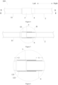
Figure 1 shows an overall structure of a pipeline assembly according to embodiments of the present disclosure. -
Figure 2 is a section view along A-A inFigure 1 . -
Figure 3 is a local enlarged drawing of part A inFigure 2 . -
Figure 4 shows an overall structure of a pipeline assembly according to embodiments of the present disclosure. -
Figure 5 is a section view along B-B inFigure 4 . -
Figure 6 is a local enlarged drawing of part B inFigure 5 . -
Figure 7 shows an overall structure of a pipeline assembly according to embodiments of the present disclosure. -
Figure 8 is a section view along C-C inFigure 7 . -
Figure 9 is a local enlarged drawing of part C inFigure 8 . -
-
pipeline assembly 100; -
first steel pipe 1; firstmain section 11; expandingsection 12;first gradient section 121; major-diameter section 122; -
second steel pipe 2; secondmain section 21; shrinkingsection 22;second gradient section 221; minor-diameter section 222; -
first copper sleeve 3;first section 31;second section 32; -
second copper sleeve 4;third section 41;fourth section 42. - Reference will be made in detail to embodiments of the present disclosure. The embodiments described herein with reference to drawings are explanatory, illustrative, and used to generally understand the present disclosure. The embodiments shall not be construed to limit the present disclosure.
- As shown in
Figures 1-3 , a pipeline assembly provided in embodiments of the present disclosure comprises afirst steel pipe 1, asecond steel pipe 2, afirst copper sleeve 3 and asecond copper sleeve 4. - The
first copper sleeve 3 is fixed on an end of thefirst steel pipe 1 and comprises afirst section 31 sheathing a periphery of thefirst steel pipe 1 and asecond section 32 extending beyond the end of thefirst steel pipe 1; thesecond copper sleeve 4 is fixed on an end of thesecond steel pipe 2 and sheathes a periphery of thesecond steel pipe 2; and thesecond section 32 sheathes at least part of thesecond copper sleeve 4 by welding. - As shown in
Figure 2 , thefirst copper sleeve 3 is fixedly welded to a terminal of one end of thefirst steel pipe 1. It should be noted that the terminal of the end of thefirst steel pipe 1 may be seemed as a small section of the end of thefirst steel pipe 1. Thefirst copper sleeve 3 has an inner diameter greater than an outer diameter of thefirst steel pipe 1, sheathing a periphery of thefirst steel pipe 1. Along an axial direction of thefirst copper sleeve 3, as shown inFigure 3 , thefirst copper sleeve 3 comprises thefirst section 31 and thesecond section 32, where thefirst section 31 sheathes the periphery of thefirst steel pipe 1 and is fixedly and hermetically welded to thefirst steel pipe 1, while thesecond section 32 extends to the outside of the end of thefirst steel pipe 1. - The
second copper sleeve 4 is fixedly welded to a terminal of one end of thesecond steel pipe 2 and has an inner diameter greater than an outer diameter of thesecond steel pipe 2, sheathing a periphery of thesecond steel pipe 2. An outer diameter of thesecond copper sleeve 4 is less than the inner diameter of thefirst copper sleeve 3. - When the
first steel pipe 1 and thesecond steel pipe 2 are butted against each other, it merely needs to insert a part of thesecond copper sleeve 4 into thesecond section 32 of thefirst copper sleeve 3 and then hermetically weld thesecond copper sleeve 4 to thesecond section 32. - It would be understood that in other embodiments, the
first copper sleeve 3 and thesecond copper sleeve 4 may be screw-fitted with thefirst steel pipe 1 and thesecond steel pipe 2, respectively. - The
pipeline assembly 100 according to embodiments of the present disclosure avoids direct welding between steel materials, thus avoiding requirements for expensive silver-containing solder thereby reducing the welding cost. In addition, thefirst copper sleeve 3 and thefirst steel pipe 1 as well as thesecond copper sleeve 4 and thesecond steel pipe 2 may be fixedly connected in advance by adopting a tunnel furnace brazing manner; while thefirst copper sleeve 3 and thesecond copper sleeve 4 may be welded with a manual flame during the on-site assembly of the air conditioner, and then, thefirst copper sleeve 3 and thesecond copper sleeve 4 may also be fused with the manual flame during the maintenance. Accordingly, on the one hand the pipeline assembly provided by embodiments of the present disclosure realizes replacing steel materials with copper materials for the refrigerant pipe thereby reducing the cost of the refrigerant pipe; and on the other hand, as the on-site assembly still relates to the welding of copper materials, the welding of the refrigeration pipe is matched with the existing welding equipment and welding process, thereby improving the adaptability and facilitating the assembly and maintenance of the air conditioning system. - In some embodiments, the
second copper sleeve 4 comprises athird section 41 and afourth section 42, where a periphery of thethird section 41 is sheathed by thesecond section 32, and an expose of thefourth section 42 is exposed to the outside. As shown inFigure 3 , thesecond copper sleeve 4 along its axial direction comprises thethird section 41 and thefourth section 42, where thethird section 41 is for inserting into and welding to thesecond section 32 of thefirst copper sleeve 3, while thefourth section 42 is arranged at the outside of thefirst copper sleeve 3 welded with thesecond copper sleeve 4. Arrangement of thefourth section 42 can prevent thesecond steel pipe 2 from being overburned during the welding of thefirst copper sleeve 3 to thesecond copper sleeve 4, thereby ensuring connection strength among the refrigerant pipes of the air conditioner. - In some embodiments, the
fourth section 42 has a length L1 along the axial direction of thesecond copper sleeve 4, where 5 mm ≤ L1 ≤ 30 mm. As shown inFigure 3 , thefourth section 42 has the length L1 which may be any value between 5 mm to 30 mm. for example, L1 may be 5 mm, 8 mm, 11 mm, 18 mm, 20 mm, 22 mm, 25 mm, 28 mm, 29 mm, 30 mm, etc. The design for the length of thefourth section 42 on the one hand can reduce the material consumption of thesecond copper sleeve 4, and prevent thesecond steel pipe 2 from being overheated on the other hand. - In some embodiments, the
first steel pipe 1 comprises a firstmain section 11 and an expandingsection 12 which is arranged at an end of the firstmain section 11 and has an inner diameter greater than that of the firstmain section 11, where a periphery of the expandingsection 12 is sheathed by thefirst section 31. As shown inFigures 4 and 5 , thefirst steel pipe 1 along its axial direction may be divided into the firstmain section 11 and the expandingsection 12, where the firstmain section 11 is the main body of thefirst steel pipe 1, while the expandingsection 12 is arranged at a terminal of the end of the firstmain section 11, with the inner diameter greater than that of the firstmain section 11. Arrangement of the expandingsection 12 improves the adaptability between thefirst steel pipe 1 and thefirst copper sleeve 3 in the size, without requirements of thefirst steel pipe 1 with larger radial sizes, which is thereby convenient to adjust the inner diameter of the firstmain section 11 to be substantially the same as that of thesecond steel pipe 2. - In some embodiments, the expanding
section 12 comprises afirst gradient section 121 and a major-diameter section 122, where thefirst gradient section 121 is connected between the firstmain section 11 and the major-diameter section 122; thefirst section 31 sheathes a periphery of the major-diameter section 122; and thefirst gradient section 121 has a cross section in a frustum shape along an axial direction of thefirst steel pipe 1. - As shown in
Figure 6 , thefirst gradient section 121 is arranged between the firstmain section 11 and the major-diameter section 122, where thefirst gradient section 121 is of a frustum shape substantially and the major-diameter section 122 is a straight pipe, and thefirst gradient section 121 provides a size transition between the firstmain section 11 and the major-diameter section 122. The major-diameter section 122 having a consistent outer diameter facilitates the welding and assembly with thefirst copper sleeve 3. - In some embodiments, the
first gradient section 121 has a length L2 which is equals to or greater than 3 mm along the axial direction of thefirst steel pipe 1. For example, L2 may be 3 mm, 4 mm, 5 mm, 6 mm, 7 mm, 8 mm, etc. Thefirst gradient section 121 with above sizes is conducive to improving its structural strength. - In some embodiments, the
second steel pipe 2 comprises: a secondmain section 21 and a shrinkingsection 22, where the shrinkingsection 22 is arranged at an end of the secondmain section 21 and has an inner diameter less than that of the secondmain section 21, and a periphery of the shrinkingsection 22 is sheathed by thesecond copper sleeve 4. - As shown in
Figures 7 and 8 , thesecond steel pipe 2 along its axial direction may be divided into the secondmain section 21 and the shrinkingsection 22, where the secondmain section 21 is the main body of thesecond steel pipe 2, while the shrinkingsection 22 is arranged at a terminal of the end of the secondmain section 21, with the inner diameter less than that of the secondmain section 21. Arrangement of the shrinkingsection 22 improves the adaptability between thesecond steel pipe 2 and thesecond copper sleeve 4 in the size, without requirements of thesecond steel pipe 2 with smaller radial sizes, which is thereby convenient to adjust the inner diameter of the secondmain section 21 to be substantially the same as that of thefirst steel pipe 1. - In some embodiments, the shrinking
section 22 comprises asecond gradient section 221 and a minor-diameter section 222, where thesecond gradient section 221 is connected between the secondmain section 21 and the minor-diameter section 222; a periphery of the minor-diameter section 222 is sheathed by thesecond copper sleeve 4; and thesecond gradient section 221 has a cross section in a frustum shape along an axial direction of thesecond steel pipe 2. - As shown in
Figure 9 , thesecond gradient section 221 is arranged between the secondmain section 21 and the minor-diameter section 222, where thesecond gradient section 221 is of a frustum shape substantially and the minor-diameter section 222 is a straight pipe, and thesecond gradient section 221 provides a size transition between the secondmain section 21 and the minor-diameter section 222. The minor-diameter section 222 having a consistent outer diameter facilitates the welding and assembly with thesecond copper sleeve 4. - In some embodiments, the
second gradient section 221 has a length L3 which is equals to or greater than 3 mm along the axial direction of thesecond steel pipe 2. For example, L3 may be 3 mm, 4 mm, 5 mm, 6 mm, 7 mm, 8 mm, etc. Thesecond gradient section 221 with above sizes is conducive to improving its structural strength. - In some embodiments, the
first copper sleeve 3 has a pipe wall thickness t1, and thesecond copper sleeve 4 has a pipe wall thickness t2, where 0.5 mm ≤ t1 ≤ 2 mm, 0.3 mm ≤ t2 ≤ 0.8 mm. - As shown in
Figure 3 , the pipe wall thickness t1 may be any value between 0.5 mm to 2 mm. For example, the pipe wall thickness t1 may be 0.5 mm, 0.8 mm, 1.0 mm, 1.2 mm, 1.5 mm, 1.7 mm, 1.9 mm, 2.0 mm, etc. The pipe wall thickness t2 may be any value between 0.3 mm and 0.8 mm. For example, the pipe wall thickness t2 may be 0.3 mm, 0.4 mm, 0.5 mm, 0.6 mm, 0.7 mm, 0.8 mm, etc. - Thus, it not only ensures the structural strength of the
first copper sleeve 3 and thesecond copper sleeve 4, but also facilitates the size matching of the two. - In some embodiments, the
first steel pipe 1 and thesecond steel pipe 2 are both stainless steel pipes, and thefirst copper sleeve 3 and thesecond copper sleeve 4 are both red copper sleeves, where thefirst steel pipe 1 is welded to thefirst copper sleeve 3 while thesecond steel pipe 2 is welded to thesecond copper sleeve 4. The first copper sleeve and the first steel pipe, as well as the second copper sleeve and the second steel pipe, may be welded by adopting a tunnel furnace brazing manner. As the welding temperature of the tunnel furnace brazing is lower than that of the manual flame welding, the welding of thefirst copper sleeve 3 to thesecond copper sleeve 4 by the manual flame is of low influence on the welding strengths between thefirst steel pipe 1 and thefirst copper sleeve 3 as well as between thesecond steel pipe 2 and thesecond copper sleeve 4. - In some embodiments, the
first steel pipe 1 may be a straight pipe or bent pipe, and thesecond steel pipe 2 may be a straight pipe or bent pipe. - An air conditioning system according to embodiments of the present disclosure is described below.
- The air conditioning system according to embodiments of the present disclosure comprises a pipeline assembly, which may be a
pipeline assembly 100 as described in the above embodiments. The air conditioning system comprises a compressor, an evaporator, a condenser, etc. Thepipeline assembly 100 may be connected between the compressor and the evaporator, or between the compressor and the condenser. - The air conditioning system according to embodiments of the present disclosure comprises the
pipeline assembly 100 which is of low cost and high adaptability to the existing welding equipment and welding process. - In the specification, it should be understood that, the terms indicating orientation or position relationship such as "central", "longitudinal", "lateral", "length", "width", "thickness", "above", "below", "front", "rear", "right", "left", "vertical", "horizontal", "top", "bottom", "inner", "outer", "clockwise", "counter-clockwise", "axial", "radial", "circumferential" should be construed to refer to the orientation or position relationship as then described or as shown in the drawings. These terms are merely for convenience and concision of description and do not alone indicate or imply that the device or element referred to must have a particular orientation or must be configured or operated in a particular orientation. Thus, it cannot be understood to limit the present disclosure.
- In addition, terms such as "first" and "second" are used herein for purposes of description and are not intended to indicate or imply relative importance or significance or impliedly indicate quantity of the technical feature referred to. Thus, the feature defined with "first" and "second" may comprise one or more this feature. In the description of the present disclosure, "a plurality of" means two or more than two this features, unless specified otherwise.
- In the present disclosure, unless specified or limited otherwise, the terms "mounted," "connected," "coupled," "fixed" and the like are used broadly, and may be, for example, fixed connections, detachable connections, or integral connections; may also be mechanical or electrical connections, or be intercommunicated; may also be direct connections or indirect connections via intervening structures; may also be inner communications of two elements, which can be understood by those skilled in the art according to specific situations.
- In the present disclosure, unless specified or limited otherwise, a structure in which a first feature is "on" or "below" a second feature may be an embodiment in which the first feature is in direct contact with the second feature, or an embodiment in which the first feature and the second feature are contacted indirectly via an intermediation. Furthermore, a first feature "on", "above" or "on top of" a second feature may comprise an embodiment in which the first feature is right or obliquely "on", "above" or "on top of" the second feature, or just means that the first feature is at a height higher than that of the second feature; while a first feature "below", "under" or "on bottom of" a second feature may comprise an embodiment in which the first feature is right or obliquely "below", "under" or "on bottom of" the second feature, or just means that the first feature is at a height lower than that of the second feature.
- Reference throughout this specification to "an embodiment", "some embodiments", "one embodiment", "another example", "an example", "a specific example" or "some examples" means that a particular feature, structure, material, or characteristic described in connection with the embodiment or example is comprised in at least one embodiment or example of the present disclosure. Thus, the appearances of the phrases such as "in some embodiments", "in one embodiment", "in an embodiment", "in another example", "in an example", "in a specific example" or "in some examples", in various places throughout this specification are not necessarily referring to the same embodiment or example of the present disclosure. Furthermore, the particular features, structures, materials, or characteristics may be combined in any suitable manner in one or more embodiments or examples.
- Although explanatory embodiments have been shown and described, it would be appreciated by those skilled in the art that the above embodiments cannot be construed to limit the present disclosure, and changes, alternatives, and modifications can be made in the embodiments in the scope of the present disclosure.
Claims (12)
- A pipeline assembly, comprising:a first steel pipe;a second steel pipe;a first copper sleeve; anda second copper sleeve,wherein the first copper sleeve is fixed on an end of the first steel pipe and comprises a first section sheathing a periphery of the first steel pipe and a second section extending beyond the end of the first steel pipe, the second copper sleeve is fixed on an end of the second steel pipe and sheathes a periphery of the second steel pipe, the second section sheathes at least a part of the second copper sleeve by welding.
- The pipeline assembly according to claim 1, wherein the second copper sleeve comprises a third section and a fourth section, wherein a periphery of the third section is sheathed by the second section, and the fourth section is exposed to the outside.
- The pipeline assembly according to claim 2, wherein the fourth section has a length L1 along an axial direction of the second copper sleeve, wherein 5 mm ≤ L1 ≤ 30 mm.
- The pipeline assembly according to any one of claims 1 to 3, wherein the first steel pipe comprises: a first main section; and an expanding section, wherein the expending section being arranged at an end of the first main section and having an inner diameter greater than an inner diameter of the first main section, wherein a periphery of the expanding section is sheathed by the first section.
- The pipeline assembly according to claim 4, wherein the expanding section comprises a major-diameter section and a first gradient section, the first gradient section is connected between the first main section and the major-diameter section, a periphery of the major-diameter section is sheathed by the first section, the first gradient section has a cross section in a frustum shape along an axial direction of the first steel pipe.
- The pipeline assembly according to claim 5, wherein the first gradient section has a length L2 equals to or greater than 3 mm along the axial direction of the first steel pipe.
- The pipeline assembly according to any one of claims 1 to 6, wherein the second steel pipe comprises: a second main section; and a shrinking section, wherein the shrinking section being arranged at an end of the second main section and having an inner diameter less than an inner diameter of the second main section, wherein a periphery of the shrinking section is sheathed by the second copper sleeve.
- The pipeline assembly according to claim 7, wherein the shrinking section comprises a minor-diameter section and a second gradient section, the second gradient section is connected between the second main section and the minor-diameter section, a periphery of the minor-diameter section is sheathed by the second copper sleeve, the second gradient section has a cross section in a frustum shape along an axial direction of the second steel pipe.
- The pipeline assembly according to claim 8, wherein the second gradient section has a length L3 equals to or greater than 3 mm along the axial direction of the second steel pipe.
- The pipeline assembly according to any one of claims 1 to 9, wherein the first copper sleeve has a pipe wall thickness t1, and the second copper sleeve has a pipe wall thickness t2, wherein 0.5 mm ≤ t1 ≤ 2 mm, 0.3 mm ≤ t2 ≤ 0.8 mm.
- The pipeline assembly according to any one of claims 1 to 10, wherein the first steel pipe and the second steel pipe are stainless steel pipes, the first steel pipe is welded to the first copper sleeve, the second steel pipe is welded to the second copper sleeve.
- An air conditioning system, comprising a pipeline assembly according to any one of claims 1 to 11.
Applications Claiming Priority (2)
| Application Number | Priority Date | Filing Date | Title |
|---|---|---|---|
| CN202121047547.9U CN215372883U (en) | 2021-05-14 | 2021-05-14 | Plumbing Components and Air Conditioning Systems |
| PCT/CN2021/137189 WO2022237152A1 (en) | 2021-05-14 | 2021-12-10 | Pipeline assembly and air conditioning system |
Publications (3)
| Publication Number | Publication Date |
|---|---|
| EP4306834A1 true EP4306834A1 (en) | 2024-01-17 |
| EP4306834A4 EP4306834A4 (en) | 2024-08-28 |
| EP4306834B1 EP4306834B1 (en) | 2025-11-26 |
Family
ID=79630349
Family Applications (1)
| Application Number | Title | Priority Date | Filing Date |
|---|---|---|---|
| EP21941714.4A Active EP4306834B1 (en) | 2021-05-14 | 2021-12-10 | Pipeline assembly and air conditioning system |
Country Status (6)
| Country | Link |
|---|---|
| US (1) | US12253191B2 (en) |
| EP (1) | EP4306834B1 (en) |
| CN (1) | CN215372883U (en) |
| AU (1) | AU2021444627B2 (en) |
| ES (1) | ES3060441T3 (en) |
| WO (1) | WO2022237152A1 (en) |
Families Citing this family (3)
| Publication number | Priority date | Publication date | Assignee | Title |
|---|---|---|---|---|
| CN115306961B (en) * | 2022-07-26 | 2023-04-25 | 含山瑞可金属有限公司 | Combined pipe fitting and air conditioning system pipeline |
| CN222230966U (en) * | 2024-05-14 | 2024-12-24 | 浙江盾安人工环境股份有限公司 | Pipeline assembly and air conditioning system |
| CN222670221U (en) * | 2024-06-17 | 2025-03-25 | 广东美的暖通设备有限公司 | Fluid pipeline and heating and ventilation device |
Family Cites Families (10)
| Publication number | Priority date | Publication date | Assignee | Title |
|---|---|---|---|---|
| US7243409B2 (en) * | 2003-07-09 | 2007-07-17 | Lewis John K | Weldable conduit method of forming |
| US8752568B2 (en) * | 2007-01-11 | 2014-06-17 | Neal L. Keefer | Low mass draw and return tube assembly and process of manufacturing the same |
| CN205781506U (en) * | 2016-07-20 | 2016-12-07 | 浙江三花股份有限公司 | A kind of four-way change-over valve adapter, four-way change-over valve and coolant circulating system |
| CN109570791B (en) | 2018-12-24 | 2021-01-22 | 中国工程物理研究院应用电子学研究所 | Resonant cavity welding method for gyrotron |
| CN110043721A (en) * | 2019-03-15 | 2019-07-23 | 沪东中华造船(集团)有限公司 | A kind of manufacturing method of coating steel pipe connecting pipe connector |
| AU2020323253B2 (en) * | 2019-07-31 | 2024-02-01 | Daikin Industries, Ltd. | Refrigeration apparatus, and refrigerant piping of refrigeration apparatus |
| AU2020322690B2 (en) * | 2019-07-31 | 2023-11-23 | Daikin Industries, Ltd. | Refrigerant pipeline, and refrigeration device |
| CN112178308A (en) | 2020-09-21 | 2021-01-05 | 浙江盾安人工环境股份有限公司 | Pipe fitting connecting structure |
| CN213809293U (en) | 2020-12-07 | 2021-07-27 | 广东美的暖通设备有限公司 | Pipes and Air Conditioners |
| CN215410630U (en) | 2021-05-14 | 2022-01-04 | 广东美的暖通设备有限公司 | Pipeline connection structure and compressor assembly |
-
2021
- 2021-05-14 CN CN202121047547.9U patent/CN215372883U/en not_active Expired - Fee Related
- 2021-12-10 ES ES21941714T patent/ES3060441T3/en active Active
- 2021-12-10 US US18/555,244 patent/US12253191B2/en active Active
- 2021-12-10 AU AU2021444627A patent/AU2021444627B2/en active Active
- 2021-12-10 EP EP21941714.4A patent/EP4306834B1/en active Active
- 2021-12-10 WO PCT/CN2021/137189 patent/WO2022237152A1/en not_active Ceased
Also Published As
| Publication number | Publication date |
|---|---|
| WO2022237152A1 (en) | 2022-11-17 |
| EP4306834B1 (en) | 2025-11-26 |
| CN215372883U (en) | 2021-12-31 |
| EP4306834A4 (en) | 2024-08-28 |
| US12253191B2 (en) | 2025-03-18 |
| AU2021444627B2 (en) | 2025-03-13 |
| AU2021444627A1 (en) | 2023-11-02 |
| US20240200696A1 (en) | 2024-06-20 |
| ES3060441T3 (en) | 2026-03-26 |
Similar Documents
| Publication | Publication Date | Title |
|---|---|---|
| US12253191B2 (en) | Pipeline assembly and air conditioning system | |
| EP3141858B1 (en) | Bended heat exchanger | |
| CN205781506U (en) | A kind of four-way change-over valve adapter, four-way change-over valve and coolant circulating system | |
| KR20080063150A (en) | heat transmitter | |
| CN103913092A (en) | Fin and heat exchanger | |
| JPH08247678A (en) | Heat-exchanger made of aluminum | |
| CN215373051U (en) | Refrigerant pipeline and air conditioner | |
| CN114630996A (en) | Plate-type refrigerant pipe and refrigeration device | |
| CN114641658A (en) | Plate-type refrigerant pipe and refrigeration device | |
| CN201173346Y (en) | Bending-resistant copper-aluminum connecting pipe structure with joint provided with reinforcing ribs | |
| US11585609B2 (en) | Bent heat exchanger | |
| KR101422074B1 (en) | Structure for fixing heat exchanger in outlet pipe | |
| US20250116440A1 (en) | Pressure vessel and refrigeration apparatus | |
| KR100803774B1 (en) | Installation piping of air conditioner | |
| CN213871611U (en) | Pipeline connecting assembly | |
| CN111288832B (en) | Collecting pipe and heat exchanger | |
| CN215373050U (en) | Compressor pipeline assembly, compressor and air conditioner | |
| CN220541327U (en) | Integrated structure pipeline piece | |
| CN223549983U (en) | Refrigerant pipeline cabin penetrating mechanism for vacuum cabin body | |
| CN218583820U (en) | Heat exchanger | |
| US20230341196A1 (en) | Connecting pipe assembly and heat exchanger | |
| CN213713307U (en) | Connecting pipe for air conditioner and air conditioner | |
| CN209944813U (en) | Combined wire-tube condenser | |
| JP5056399B2 (en) | Hermetic compressor | |
| EP4113036A1 (en) | Three-way pipe, heat exchanger, heat exchanger assembly and refrigeration apparatus |
Legal Events
| Date | Code | Title | Description |
|---|---|---|---|
| STAA | Information on the status of an ep patent application or granted ep patent |
Free format text: STATUS: THE INTERNATIONAL PUBLICATION HAS BEEN MADE |
|
| PUAI | Public reference made under article 153(3) epc to a published international application that has entered the european phase |
Free format text: ORIGINAL CODE: 0009012 |
|
| STAA | Information on the status of an ep patent application or granted ep patent |
Free format text: STATUS: REQUEST FOR EXAMINATION WAS MADE |
|
| 17P | Request for examination filed |
Effective date: 20231011 |
|
| AK | Designated contracting states |
Kind code of ref document: A1 Designated state(s): AL AT BE BG CH CY CZ DE DK EE ES FI FR GB GR HR HU IE IS IT LI LT LU LV MC MK MT NL NO PL PT RO RS SE SI SK SM TR |
|
| DAV | Request for validation of the european patent (deleted) | ||
| DAX | Request for extension of the european patent (deleted) | ||
| A4 | Supplementary search report drawn up and despatched |
Effective date: 20240731 |
|
| RIC1 | Information provided on ipc code assigned before grant |
Ipc: F24F 13/02 20060101ALI20240725BHEP Ipc: F16L 21/00 20060101ALI20240725BHEP Ipc: F16L 13/02 20060101AFI20240725BHEP |
|
| GRAP | Despatch of communication of intention to grant a patent |
Free format text: ORIGINAL CODE: EPIDOSNIGR1 |
|
| STAA | Information on the status of an ep patent application or granted ep patent |
Free format text: STATUS: GRANT OF PATENT IS INTENDED |
|
| INTG | Intention to grant announced |
Effective date: 20250626 |
|
| GRAS | Grant fee paid |
Free format text: ORIGINAL CODE: EPIDOSNIGR3 |
|
| GRAA | (expected) grant |
Free format text: ORIGINAL CODE: 0009210 |
|
| STAA | Information on the status of an ep patent application or granted ep patent |
Free format text: STATUS: THE PATENT HAS BEEN GRANTED |
|
| AK | Designated contracting states |
Kind code of ref document: B1 Designated state(s): AL AT BE BG CH CY CZ DE DK EE ES FI FR GB GR HR HU IE IS IT LI LT LU LV MC MK MT NL NO PL PT RO RS SE SI SK SM TR |
|
| REG | Reference to a national code |
Ref country code: CH Ref legal event code: F10 Free format text: ST27 STATUS EVENT CODE: U-0-0-F10-F00 (AS PROVIDED BY THE NATIONAL OFFICE) Effective date: 20251126 Ref country code: GB Ref legal event code: FG4D |
|
| REG | Reference to a national code |
Ref country code: IE Ref legal event code: FG4D |
|
| REG | Reference to a national code |
Ref country code: DE Ref legal event code: R096 Ref document number: 602021043396 Country of ref document: DE |
|
| PGFP | Annual fee paid to national office [announced via postgrant information from national office to epo] |
Ref country code: DE Payment date: 20251212 Year of fee payment: 5 |
|
| PGFP | Annual fee paid to national office [announced via postgrant information from national office to epo] |
Ref country code: AT Payment date: 20260113 Year of fee payment: 5 |
|
| REG | Reference to a national code |
Ref country code: ES Ref legal event code: FG2A Ref document number: 3060441 Country of ref document: ES Kind code of ref document: T3 Effective date: 20260326 |
|
| REG | Reference to a national code |
Ref country code: NL Ref legal event code: MP Effective date: 20251126 |
|
| PGFP | Annual fee paid to national office [announced via postgrant information from national office to epo] |
Ref country code: ES Payment date: 20260105 Year of fee payment: 5 |
|
| REG | Reference to a national code |
Ref country code: LT Ref legal event code: MG9D |
|
| PG25 | Lapsed in a contracting state [announced via postgrant information from national office to epo] |
Ref country code: NO Free format text: LAPSE BECAUSE OF FAILURE TO SUBMIT A TRANSLATION OF THE DESCRIPTION OR TO PAY THE FEE WITHIN THE PRESCRIBED TIME-LIMIT Effective date: 20260226 |
|
| PG25 | Lapsed in a contracting state [announced via postgrant information from national office to epo] |
Ref country code: HR Free format text: LAPSE BECAUSE OF FAILURE TO SUBMIT A TRANSLATION OF THE DESCRIPTION OR TO PAY THE FEE WITHIN THE PRESCRIBED TIME-LIMIT Effective date: 20251126 Ref country code: FI Free format text: LAPSE BECAUSE OF FAILURE TO SUBMIT A TRANSLATION OF THE DESCRIPTION OR TO PAY THE FEE WITHIN THE PRESCRIBED TIME-LIMIT Effective date: 20251126 Ref country code: AT Free format text: LAPSE BECAUSE OF FAILURE TO SUBMIT A TRANSLATION OF THE DESCRIPTION OR TO PAY THE FEE WITHIN THE PRESCRIBED TIME-LIMIT Effective date: 20251126 |
|
| PGFP | Annual fee paid to national office [announced via postgrant information from national office to epo] |
Ref country code: IT Payment date: 20260223 Year of fee payment: 5 |
|
| REG | Reference to a national code |
Ref country code: AT Ref legal event code: MK05 Ref document number: 1861352 Country of ref document: AT Kind code of ref document: T Effective date: 20251126 |
|
| PG25 | Lapsed in a contracting state [announced via postgrant information from national office to epo] |
Ref country code: NL Free format text: LAPSE BECAUSE OF FAILURE TO SUBMIT A TRANSLATION OF THE DESCRIPTION OR TO PAY THE FEE WITHIN THE PRESCRIBED TIME-LIMIT Effective date: 20251126 |
|
| PG25 | Lapsed in a contracting state [announced via postgrant information from national office to epo] |
Ref country code: RS Free format text: LAPSE BECAUSE OF FAILURE TO SUBMIT A TRANSLATION OF THE DESCRIPTION OR TO PAY THE FEE WITHIN THE PRESCRIBED TIME-LIMIT Effective date: 20260226 |
|
| PG25 | Lapsed in a contracting state [announced via postgrant information from national office to epo] |
Ref country code: IS Free format text: LAPSE BECAUSE OF FAILURE TO SUBMIT A TRANSLATION OF THE DESCRIPTION OR TO PAY THE FEE WITHIN THE PRESCRIBED TIME-LIMIT Effective date: 20260326 |
|
| PG25 | Lapsed in a contracting state [announced via postgrant information from national office to epo] |
Ref country code: PT Free format text: LAPSE BECAUSE OF FAILURE TO SUBMIT A TRANSLATION OF THE DESCRIPTION OR TO PAY THE FEE WITHIN THE PRESCRIBED TIME-LIMIT Effective date: 20260326 |
|
| PG25 | Lapsed in a contracting state [announced via postgrant information from national office to epo] |
Ref country code: PL Free format text: LAPSE BECAUSE OF FAILURE TO SUBMIT A TRANSLATION OF THE DESCRIPTION OR TO PAY THE FEE WITHIN THE PRESCRIBED TIME-LIMIT Effective date: 20251126 |
|
| PG25 | Lapsed in a contracting state [announced via postgrant information from national office to epo] |
Ref country code: LV Free format text: LAPSE BECAUSE OF FAILURE TO SUBMIT A TRANSLATION OF THE DESCRIPTION OR TO PAY THE FEE WITHIN THE PRESCRIBED TIME-LIMIT Effective date: 20251126 |
|
| PG25 | Lapsed in a contracting state [announced via postgrant information from national office to epo] |
Ref country code: BG Free format text: LAPSE BECAUSE OF FAILURE TO SUBMIT A TRANSLATION OF THE DESCRIPTION OR TO PAY THE FEE WITHIN THE PRESCRIBED TIME-LIMIT Effective date: 20251126 |