EP4306783A1 - Aircraft power plant with hydrogen turbo-expander - Google Patents
Aircraft power plant with hydrogen turbo-expander Download PDFInfo
- Publication number
- EP4306783A1 EP4306783A1 EP23185398.7A EP23185398A EP4306783A1 EP 4306783 A1 EP4306783 A1 EP 4306783A1 EP 23185398 A EP23185398 A EP 23185398A EP 4306783 A1 EP4306783 A1 EP 4306783A1
- Authority
- EP
- European Patent Office
- Prior art keywords
- expander
- turbo
- hydrogen gas
- combustion engine
- metal hydride
- Prior art date
- Legal status (The legal status is an assumption and is not a legal conclusion. Google has not performed a legal analysis and makes no representation as to the accuracy of the status listed.)
- Granted
Links
Images


Classifications
-
- F—MECHANICAL ENGINEERING; LIGHTING; HEATING; WEAPONS; BLASTING
- F02—COMBUSTION ENGINES; HOT-GAS OR COMBUSTION-PRODUCT ENGINE PLANTS
- F02C—GAS-TURBINE PLANTS; AIR INTAKES FOR JET-PROPULSION PLANTS; CONTROLLING FUEL SUPPLY IN AIR-BREATHING JET-PROPULSION PLANTS
- F02C7/00—Features, components parts, details or accessories, not provided for in, or of interest apart form groups F02C1/00 - F02C6/00; Air intakes for jet-propulsion plants
- F02C7/22—Fuel supply systems
- F02C7/224—Heating fuel before feeding to the burner
-
- F—MECHANICAL ENGINEERING; LIGHTING; HEATING; WEAPONS; BLASTING
- F02—COMBUSTION ENGINES; HOT-GAS OR COMBUSTION-PRODUCT ENGINE PLANTS
- F02C—GAS-TURBINE PLANTS; AIR INTAKES FOR JET-PROPULSION PLANTS; CONTROLLING FUEL SUPPLY IN AIR-BREATHING JET-PROPULSION PLANTS
- F02C3/00—Gas-turbine plants characterised by the use of combustion products as the working fluid
- F02C3/20—Gas-turbine plants characterised by the use of combustion products as the working fluid using a special fuel, oxidant, or dilution fluid to generate the combustion products
- F02C3/22—Gas-turbine plants characterised by the use of combustion products as the working fluid using a special fuel, oxidant, or dilution fluid to generate the combustion products the fuel or oxidant being gaseous at standard temperature and pressure
-
- F—MECHANICAL ENGINEERING; LIGHTING; HEATING; WEAPONS; BLASTING
- F02—COMBUSTION ENGINES; HOT-GAS OR COMBUSTION-PRODUCT ENGINE PLANTS
- F02C—GAS-TURBINE PLANTS; AIR INTAKES FOR JET-PROPULSION PLANTS; CONTROLLING FUEL SUPPLY IN AIR-BREATHING JET-PROPULSION PLANTS
- F02C3/00—Gas-turbine plants characterised by the use of combustion products as the working fluid
- F02C3/04—Gas-turbine plants characterised by the use of combustion products as the working fluid having a turbine driving a compressor
-
- B—PERFORMING OPERATIONS; TRANSPORTING
- B64—AIRCRAFT; AVIATION; COSMONAUTICS
- B64D—EQUIPMENT FOR FITTING IN OR TO AIRCRAFT; FLIGHT SUITS; PARACHUTES; ARRANGEMENT OR MOUNTING OF POWER PLANTS OR PROPULSION TRANSMISSIONS IN AIRCRAFT
- B64D41/00—Power installations for auxiliary purposes
-
- F—MECHANICAL ENGINEERING; LIGHTING; HEATING; WEAPONS; BLASTING
- F02—COMBUSTION ENGINES; HOT-GAS OR COMBUSTION-PRODUCT ENGINE PLANTS
- F02C—GAS-TURBINE PLANTS; AIR INTAKES FOR JET-PROPULSION PLANTS; CONTROLLING FUEL SUPPLY IN AIR-BREATHING JET-PROPULSION PLANTS
- F02C3/00—Gas-turbine plants characterised by the use of combustion products as the working fluid
- F02C3/20—Gas-turbine plants characterised by the use of combustion products as the working fluid using a special fuel, oxidant, or dilution fluid to generate the combustion products
- F02C3/26—Gas-turbine plants characterised by the use of combustion products as the working fluid using a special fuel, oxidant, or dilution fluid to generate the combustion products the fuel or oxidant being solid or pulverulent, e.g. in slurry or suspension
- F02C3/28—Gas-turbine plants characterised by the use of combustion products as the working fluid using a special fuel, oxidant, or dilution fluid to generate the combustion products the fuel or oxidant being solid or pulverulent, e.g. in slurry or suspension using a separate gas producer for gasifying the fuel before combustion
-
- F—MECHANICAL ENGINEERING; LIGHTING; HEATING; WEAPONS; BLASTING
- F02—COMBUSTION ENGINES; HOT-GAS OR COMBUSTION-PRODUCT ENGINE PLANTS
- F02C—GAS-TURBINE PLANTS; AIR INTAKES FOR JET-PROPULSION PLANTS; CONTROLLING FUEL SUPPLY IN AIR-BREATHING JET-PROPULSION PLANTS
- F02C6/00—Plural gas-turbine plants; Combinations of gas-turbine plants with other apparatus; Adaptations of gas-turbine plants for special use
- F02C6/18—Plural gas-turbine plants; Combinations of gas-turbine plants with other apparatus; Adaptations of gas-turbine plants for special use using the waste heat of gas-turbine plants outside the plants themselves, e.g. gas-turbine power heat plants
-
- F—MECHANICAL ENGINEERING; LIGHTING; HEATING; WEAPONS; BLASTING
- F02—COMBUSTION ENGINES; HOT-GAS OR COMBUSTION-PRODUCT ENGINE PLANTS
- F02C—GAS-TURBINE PLANTS; AIR INTAKES FOR JET-PROPULSION PLANTS; CONTROLLING FUEL SUPPLY IN AIR-BREATHING JET-PROPULSION PLANTS
- F02C7/00—Features, components parts, details or accessories, not provided for in, or of interest apart form groups F02C1/00 - F02C6/00; Air intakes for jet-propulsion plants
- F02C7/32—Arrangement, mounting, or driving, of auxiliaries
-
- F—MECHANICAL ENGINEERING; LIGHTING; HEATING; WEAPONS; BLASTING
- F05—INDEXING SCHEMES RELATING TO ENGINES OR PUMPS IN VARIOUS SUBCLASSES OF CLASSES F01-F04
- F05D—INDEXING SCHEME FOR ASPECTS RELATING TO NON-POSITIVE-DISPLACEMENT MACHINES OR ENGINES, GAS-TURBINES OR JET-PROPULSION PLANTS
- F05D2220/00—Application
- F05D2220/30—Application in turbines
- F05D2220/32—Application in turbines in gas turbines
- F05D2220/323—Application in turbines in gas turbines for aircraft propulsion, e.g. jet engines
-
- F—MECHANICAL ENGINEERING; LIGHTING; HEATING; WEAPONS; BLASTING
- F05—INDEXING SCHEMES RELATING TO ENGINES OR PUMPS IN VARIOUS SUBCLASSES OF CLASSES F01-F04
- F05D—INDEXING SCHEME FOR ASPECTS RELATING TO NON-POSITIVE-DISPLACEMENT MACHINES OR ENGINES, GAS-TURBINES OR JET-PROPULSION PLANTS
- F05D2260/00—Function
- F05D2260/20—Heat transfer, e.g. cooling
- F05D2260/213—Heat transfer, e.g. cooling by the provision of a heat exchanger within the cooling circuit
Definitions
- the disclosure relates generally to aircraft power plants, and more particularly to aircraft power plants powered with hydrogen.
- a carbon-based fuel is typically mixed with air in a combustion chamber and ignited to generate a stream of high-energy exhaust gas.
- the exhaust gas includes carbon that is eventually released into the environment. Reducing carbon emissions from aircraft engines is desirable.
- the disclosure describes a method of operating an aircraft power plant.
- the method comprises:
- the method comprises compressing the hydrogen gas released from the solid metal hydride before expanding the hydrogen gas through the turbo-expander.
- driving the load with the combustion engine includes burning a fuel other than the hydrogen gas in a combustion chamber of the combustion engine.
- the method comprises, after expanding the hydrogen gas through the turbo-expander, burning the hydrogen gas in the combustion chamber of the combustion engine.
- the method comprises, after expanding the hydrogen gas through the turbo-expander, releasing the hydrogen gas into the atmosphere.
- the combustion engine includes a gas turbine engine including a compressor; and the load includes the compressor drivingly coupled to the turbo-expander.
- driving the load with the combustion engine includes burning a fuel other than the hydrogen gas in a combustion chamber of the gas turbine engine; and after expanding the hydrogen gas through the turbo-expander, burning the hydrogen gas in the combustion chamber of the gas turbine engine.
- the load includes an electric generator.
- the method comprises transferring the work produced by the turbo-expander to the load via an accessory gearbox drivingly coupled to the combustion engine.
- the method comprises, transferring heat from the combustion engine to the solid metal hydride.
- the disclosure describes a system for driving a load onboard an aircraft.
- the system comprises:
- the system comprises a pump operatively disposed between the solid metal hydride and the turbo-expander to pressurize the hydrogen gas released from the solid metal hydride upstream of the turbo-expander.
- the system comprises a conduit conveying the hydrogen gas from the turbo-expander to a combustion chamber of the combustion engine.
- the system comprises a conduit conveying the hydrogen gas from the turbo-expander to the atmosphere.
- an aircraft power plant comprises the system as defined in any of the embodiments, and/or the aspect, above.
- an aircraft power plant comprising:
- the turbo-expander is drivingly coupled to the accessory.
- the turbo-expander is drivingly coupled to the spool of the gas turbine engine.
- the aircraft power plant comprises a conduit conveying the hydrogen gas from the turbo-expander to a combustor of the gas turbine engine.
- the aircraft power plant comprises a pump operatively disposed between the solid metal hydride and the turbo-expander to pressurize the hydrogen gas released from the solid metal hydride upstream of the turbo-expander.
- the aircraft power plants described herein may be partially powered with hydrogen in some situations.
- the aircraft power plants and method described herein may promote a reduction in carbon emission in some situations.
- the aircraft power plants described herein may produce work from the expansion of hydrogen gas released from a solid metal hydride through a turbo-expander. The work produced from the expansion of the hydrogen gas through the turbo-expander may be used to mechanically drive one or more loads onboard an aircraft.
- connection and coupling may include both direct connection and coupling (in which two elements that are coupled to each other contact each other) and indirect connection and coupling (in which at least one additional element is located between the two elements).
- indirect connection and coupling in which at least one additional element is located between the two elements.
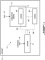
- FIG. 1 is a schematic illustration of aircraft 10 including aircraft power plant 12 (referred hereinafter as "power plant 12") as described herein.
- Aircraft 10 may be any type of manned or unmanned aircraft (e.g., drone) such as corporate, private, commercial and passenger aircraft.
- Aircraft 10 may be a fixed-wing aircraft or a rotary-wing aircraft (e.g., helicopter) including one or more power plants 12.
- power plant 12 may be configured to produce work used for the propulsion of aircraft 10 and may be operated during flight of aircraft 10.
- power plant 12 may be configured to produce thrust to propel aircraft 10.
- power plant 12 may be drivingly coupled to a propeller of a fixed-wing aircraft, or to a main rotor of a helicopter.
- power plant 12 may be configured as an auxiliary power unit (APU) that produces work for functions other than propulsion of aircraft 10.
- APU auxiliary power unit
- power plant 12 may produce electricity and/or pressurized air for use by one or more systems of aircraft 10.
- power plant 12 may mainly be operated to power systems of aircraft 10 when aircraft 10 is on the ground and main engines used for propelling aircraft 10 are turned off.
- power plant 12 may be installed in a tail cone or other suitable location within aircraft 10.
- Power plant 12 may include one or more combustion engines 14 (referred hereinafter in the singular) drivingly coupled to one or more loads 16 onboard of aircraft 10.
- combustion engine 14 may include a continuous combustion engine.
- combustion engine 14 may include a gas turbine engine in a turbofan configuration, turboprop configuration, or turboshaft configuration.
- combustion engine 14 may include an intermittent combustion engine.
- combustion engine 14 may include a reciprocating piston engine, or a rotary (e.g., Wankel) engine.
- Combustion engine 14 may be configured to drive one or more internal loads 16A that are considered part of (e.g., internal to) combustion engine 14, and/or one or more external loads 16B that are external to combustion engine 14.
- Internal loads 16A may be loads that perform functions associated with sustaining the operation of combustion engine 14.
- internal loads 16A may include: a compressor supplying air to combustion chamber 18 (shown in FIG. 2 ) of combustion engine 14; a fuel pump supplying fuel to combustion chamber 18 of combustion engine 14; an oil pump supplying oil to one or more lubrication loads of combustion engine 14; and/or one or more electric generators supplying electricity to a control system of combustion engine 14.
- External loads 16B may be loads that perform functions for purposes other than sustaining the operation of combustion engine 14.
- external loads 16B may include: a load compressor supplying air to an environmental control system (ECS) and/or to a anti-icing system of aircraft 10; an electric generator supplying electricity to a lighting or other system of aircraft 10; a propeller or fan for propelling aircraft 10; and/or a main rotor of a helicopter.
- ECS environmental control system
- helicopter main rotor of a helicopter.
- Some loads 16 may be considered both internal and external to combustion engine 14.
- compressor 20 shown in FIG. 2
- combustion engine 14 may supply some compressed air for sustaining the operation of combustion engine 14, and also supply some compressed air for supplying an ECS of aircraft 10 via a suitable bleed port.
- an electric generator driven by combustion engine 14 may supply electricity to both a control system of combustion engine 14, and to a lighting system of aircraft 10.
- combustion engine 14 may burn fuel 22 to produce work and use the work to drive one or more loads 16.
- Fuel 22 may be a carbon-based (e.g., hydrocarbon) fuel stored in liquid form onboard of aircraft 10.
- fuel 22 may be a kerosene-type jet fuel, a naphtha-type jet fuel, or a gasoline for example.
- Aircraft 10 may also include system 24 for producing work from hydrogen gas 26 and use the work to drive one or more loads 16.
- System 24 may be an energy conversion system that can produce work from hydrogen gas 26.
- combustion engine 14 and system 24 may be operable concurrently to drive load(s) 16.
- combustion engine 14 may be operable continuously and be considered a primary source of power for driving load(s) 16.
- system 24 may be continuously operable, or be selectively operable on an on-demand basis to supplement the power produced by combustion engine 14 when needed. For example, when the power demand from power plant 12 is relatively high, system 24 may be activated to provide a boost of power and assist combustion engine 14 with meeting the high power demand.
- the availability of system 24 to assist combustion engine 14 may permit combustion engine 14 to be sized for efficient operation at a nominal (e.g., average, cruise) power output level while relying on system 24 to meet peak power demands from power plant 12 when necessary.
- the same one or more loads 16 may be driveable simultaneously by both combustion engine 14 and system 24 in some situations. In some embodiments, one or more loads 16 may be driveable by combustion engine 14 while another one or more loads 16 may be driveable by system 24 in some situations.
- System 24 may use hydrogen gas 26 to produce motive power in the form of a rotation of a shaft. Such motive power may be transferred to internal load(s) 16A via one or more first mechanical connections 28A, and/or to external load(s) 16B via one or more second mechanical connections 28B. Load(s) 16 may also be drivingly coupled to combustion engine 14 via one or more third mechanical connections 28C.
- Mechanical connections 28A, 28B, 28C may include suitable mechanical couplings used to connect rotatable shafts of system 24 and of combustion engine 14 to mechanically driven pieces of equipment. In other words, mechanical connections 28A, 28B, 28C may permit torque transfer between shafts of system 24 and of combustion engine 14 to load(s) 16.
- mechanical connections 28A, 28B, 28C may include shafts and suitable speed-augmenting and/or speed-reducing gear trains.
- some mechanical connections 28A, 28B, 28C may be established via a suitable epicyclic (e.g., differential) gear train having two inputs respectively drivingly coupled to system 24 and combustion engine 14, and one output drivingly coupled to the applicable load(s) 16.
- a differential gear train may accommodate asymmetric inputs (e.g., torques, rotational speeds) from system 24 and combustion engine 14.
- some of mechanical connections 28A, 28B, 28C may include a clutch to selectively connect and disconnect system 24 and/or combustion engine 14 to/from applicable load(s) 16.
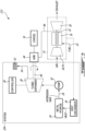
- FIG. 2 is a schematic illustration of an exemplary aircraft power plant 112 of aircraft 10.
- Power plant 112 may include system 124 for producing work from hydrogen gas 26 and using the work to drive load(s) 16 onboard of aircraft 10.
- Power plant 112 may include components previously described above in relation to power plant 12.
- Like elements are identified using like reference numerals.
- Power plant 112 may include combustion engine 14 having the form of a gas turbine engine as an example.
- Combustion engine 14 may include: multistage compressor 20 for pressurizing ambient air received into combustion engine 14; combustion chamber 18 in which the compressed air is mixed with fuel 22 and ignited for generating a stream of hot combustion gas, and turbine section 30 for extracting energy from the combustion gases and driving turbine shaft 32.
- Combustion engine 14 may be suitable for generating thrust for propelling aircraft 10, or may be suitable for use as an APU of aircraft 10.
- Combustion engine 14 may be a single-spool gas turbine engine or a multi-spool gas turbine engine.
- one or more stages of compressor 20 may be drivingly coupled to one or more stages of turbine section 30 via turbine shaft 32.
- the one or more stages of compressor 20, turbine shaft 32, and the one or more stages of turbine section 30 may define a spool of combustion engine 14 rotating as a unit.
- System 124 may include solid metal hydride 34 (referred hereinafter as "MH 34") stored in a suitable tank (e.g., canister, cartridge) onboard of aircraft 10.
- MH 34 may also be referred to as an interstitial hydride and may include any suitable type of solid hydrogen storage material including metal or metalloid bonded to hydrogen.
- MH 34 may include hydrogen stored on the surface of a solid by adsorption.
- Non-limiting examples of materials for MH 34 may include a lanthanum-nickel alloy (LaNi 5 H 6 ), aluminum hydride (AlH 3 ), magnesium hydride (MgH 2 ), sodium aluminum hydride (NaAlH 4 ), and ammonia borane (NH 3 BH 3 ).
- MH 34 may be in a powder form and may be stored in a pressurized tank.
- the storage of hydrogen as a solid in the form of MH 34 may provide a relatively high power density, promote efficient utilization of space onboard of aircraft 10, and hence promote compact packaging of power plant 112.
- MH 34 may be stored at a suitable pressure and temperature at which the hydrogen substantially remains adsorbed into MH 34.
- the storage pressure and temperature may depend on the type of MH 34 used.
- MH 34 may be stored at a pressure of about 1 MPa.
- MH 34 may be stored at a temperature between 0 °C and 50 °C for example.
- active cooling of MH 34 using cooling ambient air, a cryogenic liquid or other heat transfer fluid may be required to substantially prevent hydrogen gas 26 from being released from MH 34 when hydrogen gas 26 is not required.
- Heat may be applied to MH 34 to cause useable hydrogen gas 26 to be released from MH 34 by desorption when hydrogen gas 26 is needed.
- a suitable heat source onboard of aircraft 10 may be selectively placed in thermal communication with MH 34 via heat exchanger 36 in order to cause hydrogen gas 26 to be released from MH 34 when system 124 is to be activated.
- the source of heat may be combustion engine 14.
- waste heat from combustion engine 14 may be transferred to MH 34 by way of a suitable heat transfer fluid such as exhaust gas, oil from a lubrication system of combustion engine 14, or compressed air bled from compressor 20 of combustion engine 14.
- Heat exchanger 36 may include one or more conduits in thermal communication (e.g., in contact) with MH 34 for conveying the heat transfer fluid and facilitating heat transfer from the heat transfer fluid to MH 34.
- Such conduit(s) may be coiled within a (e.g., cylindrical) tank storing MH 34 to increase a length of such conduit(s) and increase an effective heat transfer area.
- such conduit(s) may include transverse fins, longitudinal fins, and/or dendritic fins to increase the effective heat transfer area and promote heat transfer.
- a suitable heat source may include one or more electric resistance heating elements in thermal communication with MH 34.
- an electric heating film or blanket may overlay an outer surface of MH 34 and be activated as needed to heat MH 34 and cause hydrogen gas 26 to be released.
- the heating film or blanket may be perforated to permit the passage of hydrogen gas 26 therethrough as hydrogen gas 26 is being released from MH 34.
- the temperature at which MH 34 should be heated to release hydrogen gas 26 may depend on the type of MH 34 used.
- MH 34 may be heated to between 150 °C and 200 °C to cause the release of hydrogen gas 26 for example.
- Hydrogen gas 26 released from MH 34 may be conveyed to turbo-expander 38 (i.e., expansion turbine) and permitted to expand through turbo-expander 38.
- turbo-expander 38 may be in fluid communication with MH 34 via a suitable conduit.
- Turbo-expander 38 may be a centrifugal-flow or axial-flow turbine through which pressurized hydrogen gas 26 is expanded to produce work to drive load(s) 16.
- the work produced by turbo-expander 38 may be in the form of rotation of output shaft 40 drivingly coupled to turbo-expander 38.
- the pressure of hydrogen gas 26 released from MH 34 may be increased via pump 42 upstream of turbo-expander 38.
- the use of pump 42 to increase the pressure of hydrogen gas 26 may increase the potential pressure differential of hydrogen gas 26 across turbo-expander 38 and thereby potentially increase the amount of work that can be produced by turbo-expander 38.
- pump 42 may be a centrifugal pump and may be operatively disposed between MH 34 and turbo-expander 38. Pump 42 may be driven by an electric motor or by motive power produced by combustion engine 14 for example.
- Output shaft 40 may be drivingly connected to load(s) 16.
- load(s) 16 may include one or more mechanically-driven accessories such as a gearbox, an electric generator, a fuel pump, an oil pump, a compressor, and/or other mechanically-driven device associated with a system of aircraft 10, and drivingly coupled to accessory gearbox 44 (referred hereinafter as "AGB 44").
- ABG 44 may be drivingly coupled to turbine shaft 32 via tower shaft 46.
- AGB 44 may include one or more pads/interfaces to which respective accessories may be drivingly coupled.
- loads i.e., load(s) 16
- tower shaft 46 and AGB 44 may define a mechanical connection between turbine shaft 32 and load(s) 16 to transfer work produced by combustion engine 14 to load(s) 16.
- output shaft 40 of turbo-expander 38 may be drivingly coupled to a pad/interface of AGB 44 and contribute to driving the accessories (i.e., load(s) 16) that are connected to AGB 44.
- output shaft 40 and AGB 44 may define a mechanical connection between turbo-expander 38 and load(s) 16 to transfer work produced by turbo-expander 38 to load(s) 16.
- an epicyclic gear train, differential gear train or other suitable type of gear train that may permit load(s) 16 to receive motive power from both output shaft 40 and from tower shaft 46 simultaneously.
- Such gear train may be incorporated into AGB 44 or be separate from AGB 44.
- hydrogen gas 26 may then be conveyed from turbo-expander 38 to combustion chamber 18 of combustion engine 14 via conduit 48 (e.g., pipe) so that hydrogen gas 26 may be injected into and burned in combustion chamber 18 and that additional work may be extracted from hydrogen gas 26 by combustion engine 14.
- conduit 48 e.g., pipe
- Burning hydrogen gas 26 in combustion chamber 18 can provide a sudden boost of power to rapidly accelerate combustion engine 14 during an abrupt maneuver of aircraft 10 being required, or as an afterburner during take-off of aircraft 10 for example.
- System 124 may include one or more controllers 50 (referred hereinafter in the singular) to control various operations of system 124 and optionally other operations of power plant 112.
- controller 50 may be operatively coupled to receive feedback from one or more sensors sensing operating parameters of system 124.
- Controller 50 may be operatively connected to controllable devices such as valves and electric motors to control various aspects of operation of system 124.
- controller 50 may be operatively connected to control a pressure output from pump 42, heat delivered to MH 34 by heat exchanger 36 and the operation of turbo-expander 38 for example.
- controller 50 may include or form part of a Full Authority Digital Engine Control (FADEC) which may, for example, include one or more digital computer(s) or other data processors, sometimes referred to as electronic engine controller(s) (EEC) and related accessories that control at least some aspects of performance of power plant 112. Controller 50 may for example be configured to make decisions regarding the control of power plant 112 based on input from a pilot of aircraft 10. As data processors, controller 50 may include one or more microcontrollers or other suitably programmed or programmable logic circuits.
- FADEC Full Authority Digital Engine Control
- EEC electronic engine controller
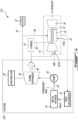
- FIG. 3 is a schematic illustration of another exemplary aircraft power plant 212 of aircraft 10.
- Power plant 212 may include system 224 for producing work from hydrogen gas 26 and using the work to drive load(s) 16 onboard of aircraft 10.
- Power plant 212 may include components previously described above in relation to power plants 12 and 112. Like elements are identified using like reference numerals.
- power plant 212 may convey hydrogen gas 26 to vent 52 via conduit 54 instead of conveying hydrogen gas 26 to combustion chamber 18 of combustion engine 14. Hydrogen gas 26 may be discharged to the atmosphere via vent 52 downstream of turbo-expander 38.
- venting hydrogen gas 26 to the atmosphere instead of retaining sufficient pressure of hydrogen gas 26 to feed hydrogen gas 26 to combustion chamber 18 may permit a greater depletion of the pressure of hydrogen gas 26 through turbo-expander 38 and thereby allow for a greater amount of work to be produced by turbo-expander 38.
- FIG. 4 is a schematic illustration of another exemplary aircraft power plant 312 of aircraft 10.
- Power plant 312 may include system 324 for producing work from hydrogen gas 26 and using the work to drive load(s) 16 onboard of aircraft 10.
- Power plant 312 may include components previously described above in relation to power plants 12, 112 and 212. Like elements are identified using like reference numerals.
- power plant 312 may include a mechanical connection between output shaft 40 of turbo-expander 38 and turbine shaft 32.
- compressor 20 may be a load 16 driven by work produced by turbo-expander 38 and also by work produced by turbine section 30 of combustion engine 14.
- the motive power transferred from turbo-expander 38 to shaft 32 may improve surge and stall margins of compressor 20.
- FIG. 4 also shows various possible configurations of power plant 312 shown in broken lines.
- work produced by turbo-expander 38 may be used to drive compressor 20 and/or other load(s) 16.
- Compressor 20 may also be driven by turbine section 30 via turbine shaft 32.
- the other load(s) 16 may be drivingly coupled to turbine shaft 32 via tower shaft 46.
- hydrogen gas 26 may be conveyed to combustion chamber 18 via conduit 48 and burned in combustion chamber 18 to extract additional work from hydrogen gas 26.
- hydrogen gas 26 may be conveyed to vent 52 via conduit 54 and discharged into the atmosphere.
- FIG. 5 is a flow diagram of a method 1000 of operating an aircraft power plant.
- Method 1000 may be performed using power plants 12, 112, 212 or 312 described herein or using another power plant.
- Method 1000 may include other actions including actions disclosed herein.
- Method 1000 may include elements of power plants 12, 112, 212 or 312 described herein.
- method 1000 may include:
- method 1000 may include compressing hydrogen gas 26 released from MH 34 (e.g., using pump 42) before expanding hydrogen gas 26 through the turbo-expander 38.
- driving load(s) 16 with combustion engine 14 may include burning a (e.g., carbon-based) fuel other than hydrogen gas 26 in combustion chamber 18 of combustion engine 14.
- a (e.g., carbon-based) fuel other than hydrogen gas 26 in combustion chamber 18 of combustion engine 14.
- method 1000 may include, after expanding hydrogen gas 26 through turbo-expander 38, burning hydrogen gas 26 in combustion chamber 18 of combustion engine 14. In some embodiments, method 1000 may alternatively or in addition, include after expanding hydrogen gas 26 through turbo-expander 38, release some or all of hydrogen gas 26 into the atmosphere (e.g., via vent 52).
- combustion engine 14 may include a gas turbine engine including compressor 20.
- Load(s) 16 driven by turbo-expander 38 may include compressor 20 drivingly coupled to turbo-expander 38.
- driving load(s) 16 with combustion engine 14 may include burning a fuel other than hydrogen gas 26 in combustion chamber 18 of the gas turbine engine. After expanding hydrogen gas 26 through turbo-expander 38, burning hydrogen gas 26 in combustion chamber 18 of the gas turbine engine.
- load(s) 16 may include an electric generator, a pump, compressor 20, and/or other mechanically-driven device associated with a system of aircraft 10.
- method 1000 may include transferring the work produced by turbo-expander 38 to load(s) 16 via AGB 44 drivingly coupled to combustion engine 14.
- heating MH 34 may include transferring heat from (e.g., generated by) combustion engine 14 to MH 34.
Landscapes
- Engineering & Computer Science (AREA)
- Chemical & Material Sciences (AREA)
- Combustion & Propulsion (AREA)
- Mechanical Engineering (AREA)
- General Engineering & Computer Science (AREA)
- Engine Equipment That Uses Special Cycles (AREA)
- Aviation & Aerospace Engineering (AREA)
Abstract
Description
- The disclosure relates generally to aircraft power plants, and more particularly to aircraft power plants powered with hydrogen.
- In an aircraft engine, a carbon-based fuel is typically mixed with air in a combustion chamber and ignited to generate a stream of high-energy exhaust gas. The exhaust gas includes carbon that is eventually released into the environment. Reducing carbon emissions from aircraft engines is desirable.
- According to one aspect of the invention, the disclosure describes a method of operating an aircraft power plant. The method comprises:
- driving a load onboard an aircraft with a combustion engine;
- heating a solid metal hydride onboard the aircraft to cause hydrogen gas to be released from the solid metal hydride;
- expanding the hydrogen gas through a turbo-expander to produce work; and
- using the work produced by the turbo-expander to drive the load.
- In an embodiment of the above the method comprises compressing the hydrogen gas released from the solid metal hydride before expanding the hydrogen gas through the turbo-expander.
- In an embodiment of any of the above, driving the load with the combustion engine includes burning a fuel other than the hydrogen gas in a combustion chamber of the combustion engine.
- In an embodiment of any of the above the method comprises, after expanding the hydrogen gas through the turbo-expander, burning the hydrogen gas in the combustion chamber of the combustion engine.
- In an embodiment of any of the above the method comprises, after expanding the hydrogen gas through the turbo-expander, releasing the hydrogen gas into the atmosphere.
- In an embodiment of any of the above, the combustion engine includes a gas turbine engine including a compressor; and the load includes the compressor drivingly coupled to the turbo-expander.
- In an embodiment of any of the above, driving the load with the combustion engine includes burning a fuel other than the hydrogen gas in a combustion chamber of the gas turbine engine; and after expanding the hydrogen gas through the turbo-expander, burning the hydrogen gas in the combustion chamber of the gas turbine engine.
- In an embodiment of any of the above, the load includes an electric generator.
- In an embodiment of any of the above the method comprises transferring the work produced by the turbo-expander to the load via an accessory gearbox drivingly coupled to the combustion engine.
- In an embodiment of any of the above the method comprises, transferring heat from the combustion engine to the solid metal hydride.
- According to another aspect of the invention, the disclosure describes a system for driving a load onboard an aircraft. The system comprises:
- a solid metal hydride;
- a source of heat in thermal communication with the solid metal hydride to cause hydrogen gas to be released from the solid metal hydride;
- a turbo-expander in fluid communication with the solid metal hydride to produce work from the hydrogen gas released from the solid metal hydride expanding through the turbo-expander;
- a first mechanical connection transferring the work produced by the turbo-expander to the load; and
- a second mechanical connection transferring work produced by a combustion engine to the load.
- In an embodiment of the above, the system comprises a pump operatively disposed between the solid metal hydride and the turbo-expander to pressurize the hydrogen gas released from the solid metal hydride upstream of the turbo-expander.
- In an embodiment of any of the above, the system comprises a conduit conveying the hydrogen gas from the turbo-expander to a combustion chamber of the combustion engine.
- In an embodiment of any of the above, the system comprises a conduit conveying the hydrogen gas from the turbo-expander to the atmosphere.
- According to a further aspect of the invention, an aircraft power plant comprises the system as defined in any of the embodiments, and/or the aspect, above.
- According to a further aspect of the invention, the disclosure describes an aircraft power plant comprising:
- a gas turbine engine drivingly coupled to an accessory, the gas turbine engine including a spool;
- a solid metal hydride;
- a heat exchanger facilitating heat transfer from the gas turbine engine to the solid metal hydride to cause hydrogen gas to be released from the solid metal hydride; and
- a turbo-expander in fluid communication with the solid metal hydride to produce work from the hydrogen gas released from the solid metal hydride expanding through the turbo-expander, the turbo-expander being drivingly coupled to the accessory and/or to the spool of the gas turbine engine.
- In an embodiment of the above, the turbo-expander is drivingly coupled to the accessory.
- In an embodiment of any of the above, the turbo-expander is drivingly coupled to the spool of the gas turbine engine.
- In an embodiment of any of the above, the aircraft power plant comprises a conduit conveying the hydrogen gas from the turbo-expander to a combustor of the gas turbine engine.
- In an embodiment of any of the above, the aircraft power plant comprises a pump operatively disposed between the solid metal hydride and the turbo-expander to pressurize the hydrogen gas released from the solid metal hydride upstream of the turbo-expander.
- Further details of these and other aspects of the subject matter of this application will be apparent from the detailed description included below and the drawings.
- Reference is now made to the accompanying drawings, in which:
-
FIG. 1 is a schematic illustration of an aircraft including an exemplary aircraft power plant as described herein; -
FIG. 2 is a schematic illustration of another exemplary aircraft power plant; -
FIG. 3 is a schematic illustration of another exemplary aircraft power plant; -
FIG. 4 is a schematic illustration of another exemplary aircraft power plant; and -
FIG. 5 is a flow diagram of a method of operating an aircraft power plant. - The following disclosure relates to aircraft power plants and associated methods. In various embodiments, the aircraft power plants described herein may be partially powered with hydrogen in some situations. In some embodiments, the aircraft power plants and method described herein may promote a reduction in carbon emission in some situations. In some embodiments, the aircraft power plants described herein may produce work from the expansion of hydrogen gas released from a solid metal hydride through a turbo-expander. The work produced from the expansion of the hydrogen gas through the turbo-expander may be used to mechanically drive one or more loads onboard an aircraft.
- The terms "connected" and "coupled to" may include both direct connection and coupling (in which two elements that are coupled to each other contact each other) and indirect connection and coupling (in which at least one additional element is located between the two elements). The term "substantially" as used herein may be applied to modify any quantitative representation which could permissibly vary without resulting in a change in the basic function to which it is related.
- Aspects of various embodiments are described through reference to the drawings.
-
FIG. 1 is a schematic illustration ofaircraft 10 including aircraft power plant 12 (referred hereinafter as "power plant 12") as described herein.Aircraft 10 may be any type of manned or unmanned aircraft (e.g., drone) such as corporate, private, commercial and passenger aircraft.Aircraft 10 may be a fixed-wing aircraft or a rotary-wing aircraft (e.g., helicopter) including one ormore power plants 12. In some embodiments,power plant 12 may be configured to produce work used for the propulsion ofaircraft 10 and may be operated during flight ofaircraft 10. For example,power plant 12 may be configured to produce thrust to propelaircraft 10. For example,power plant 12 may be drivingly coupled to a propeller of a fixed-wing aircraft, or to a main rotor of a helicopter. - In some embodiments,
power plant 12 may be configured as an auxiliary power unit (APU) that produces work for functions other than propulsion ofaircraft 10. For example,power plant 12 may produce electricity and/or pressurized air for use by one or more systems ofaircraft 10. In an APU configuration,power plant 12 may mainly be operated to power systems ofaircraft 10 whenaircraft 10 is on the ground and main engines used for propellingaircraft 10 are turned off. In an APU configuration,power plant 12 may be installed in a tail cone or other suitable location withinaircraft 10. -
Power plant 12 may include one or more combustion engines 14 (referred hereinafter in the singular) drivingly coupled to one ormore loads 16 onboard ofaircraft 10. In various embodiments,combustion engine 14 may include a continuous combustion engine. For example,combustion engine 14 may include a gas turbine engine in a turbofan configuration, turboprop configuration, or turboshaft configuration. In some embodiments,combustion engine 14 may include an intermittent combustion engine. For example,combustion engine 14 may include a reciprocating piston engine, or a rotary (e.g., Wankel) engine. -
Combustion engine 14 may be configured to drive one or moreinternal loads 16A that are considered part of (e.g., internal to)combustion engine 14, and/or one or moreexternal loads 16B that are external tocombustion engine 14.Internal loads 16A may be loads that perform functions associated with sustaining the operation ofcombustion engine 14. For example,internal loads 16A may include: a compressor supplying air to combustion chamber 18 (shown inFIG. 2 ) ofcombustion engine 14; a fuel pump supplying fuel tocombustion chamber 18 ofcombustion engine 14; an oil pump supplying oil to one or more lubrication loads ofcombustion engine 14; and/or one or more electric generators supplying electricity to a control system ofcombustion engine 14. -
External loads 16B may be loads that perform functions for purposes other than sustaining the operation ofcombustion engine 14. For example,external loads 16B may include: a load compressor supplying air to an environmental control system (ECS) and/or to a anti-icing system ofaircraft 10; an electric generator supplying electricity to a lighting or other system ofaircraft 10; a propeller or fan for propellingaircraft 10; and/or a main rotor of a helicopter. - Some loads 16 may be considered both internal and external to
combustion engine 14. For example, compressor 20 (shown inFIG. 2 ) ofcombustion engine 14 may supply some compressed air for sustaining the operation ofcombustion engine 14, and also supply some compressed air for supplying an ECS ofaircraft 10 via a suitable bleed port. Similarly, an electric generator driven bycombustion engine 14 may supply electricity to both a control system ofcombustion engine 14, and to a lighting system ofaircraft 10. - During operation,
combustion engine 14 may burnfuel 22 to produce work and use the work to drive one or more loads 16.Fuel 22 may be a carbon-based (e.g., hydrocarbon) fuel stored in liquid form onboard ofaircraft 10. In various embodiments,fuel 22 may be a kerosene-type jet fuel, a naphtha-type jet fuel, or a gasoline for example. -
Aircraft 10 may also includesystem 24 for producing work fromhydrogen gas 26 and use the work to drive one or more loads 16.System 24 may be an energy conversion system that can produce work fromhydrogen gas 26. In some embodiments,combustion engine 14 andsystem 24 may be operable concurrently to drive load(s) 16. In some embodiments,combustion engine 14 may be operable continuously and be considered a primary source of power for driving load(s) 16. In some embodiments,system 24 may be continuously operable, or be selectively operable on an on-demand basis to supplement the power produced bycombustion engine 14 when needed. For example, when the power demand frompower plant 12 is relatively high,system 24 may be activated to provide a boost of power and assistcombustion engine 14 with meeting the high power demand. In some embodiments, the availability ofsystem 24 to assistcombustion engine 14 may permitcombustion engine 14 to be sized for efficient operation at a nominal (e.g., average, cruise) power output level while relying onsystem 24 to meet peak power demands frompower plant 12 when necessary. - In some embodiments, the same one or
more loads 16 may be driveable simultaneously by bothcombustion engine 14 andsystem 24 in some situations. In some embodiments, one ormore loads 16 may be driveable bycombustion engine 14 while another one ormore loads 16 may be driveable bysystem 24 in some situations. -
System 24 may usehydrogen gas 26 to produce motive power in the form of a rotation of a shaft. Such motive power may be transferred to internal load(s) 16A via one or more firstmechanical connections 28A, and/or to external load(s) 16B via one or more secondmechanical connections 28B. Load(s) 16 may also be drivingly coupled tocombustion engine 14 via one or more thirdmechanical connections 28C.Mechanical connections system 24 and ofcombustion engine 14 to mechanically driven pieces of equipment. In other words,mechanical connections system 24 and ofcombustion engine 14 to load(s) 16. In some embodiments,mechanical connections combustion engine 14 andsystem 24, somemechanical connections system 24 andcombustion engine 14, and one output drivingly coupled to the applicable load(s) 16. In some embodiments, a differential gear train may accommodate asymmetric inputs (e.g., torques, rotational speeds) fromsystem 24 andcombustion engine 14. In some embodiments, some ofmechanical connections disconnect system 24 and/orcombustion engine 14 to/from applicable load(s) 16. -
FIG. 2 is a schematic illustration of an exemplaryaircraft power plant 112 ofaircraft 10.Power plant 112 may includesystem 124 for producing work fromhydrogen gas 26 and using the work to drive load(s) 16 onboard ofaircraft 10.Power plant 112 may include components previously described above in relation topower plant 12. Like elements are identified using like referencenumerals. Power plant 112 may includecombustion engine 14 having the form of a gas turbine engine as an example.Combustion engine 14 may include: multistage compressor 20 for pressurizing ambient air received intocombustion engine 14;combustion chamber 18 in which the compressed air is mixed withfuel 22 and ignited for generating a stream of hot combustion gas, andturbine section 30 for extracting energy from the combustion gases and drivingturbine shaft 32. -
Combustion engine 14 may be suitable for generating thrust for propellingaircraft 10, or may be suitable for use as an APU ofaircraft 10.Combustion engine 14 may be a single-spool gas turbine engine or a multi-spool gas turbine engine. For example, one or more stages of compressor 20 may be drivingly coupled to one or more stages ofturbine section 30 viaturbine shaft 32. The one or more stages of compressor 20,turbine shaft 32, and the one or more stages ofturbine section 30 may define a spool ofcombustion engine 14 rotating as a unit. -
System 124 may include solid metal hydride 34 (referred hereinafter as "MH 34") stored in a suitable tank (e.g., canister, cartridge) onboard ofaircraft 10.MH 34 may also be referred to as an interstitial hydride and may include any suitable type of solid hydrogen storage material including metal or metalloid bonded to hydrogen.MH 34 may include hydrogen stored on the surface of a solid by adsorption. Non-limiting examples of materials forMH 34 may include a lanthanum-nickel alloy (LaNi5H6), aluminum hydride (AlH3), magnesium hydride (MgH2), sodium aluminum hydride (NaAlH4), and ammonia borane (NH3BH3).MH 34 may be in a powder form and may be stored in a pressurized tank. In some embodiments, the storage of hydrogen as a solid in the form ofMH 34 may provide a relatively high power density, promote efficient utilization of space onboard ofaircraft 10, and hence promote compact packaging ofpower plant 112. -
MH 34 may be stored at a suitable pressure and temperature at which the hydrogen substantially remains adsorbed intoMH 34. The storage pressure and temperature may depend on the type ofMH 34 used. In some embodiments,MH 34 may be stored at a pressure of about 1 MPa. In some embodiments,MH 34 may be stored at a temperature between 0 °C and 50 °C for example. In some embodiments, active cooling ofMH 34 using cooling ambient air, a cryogenic liquid or other heat transfer fluid may be required to substantially preventhydrogen gas 26 from being released fromMH 34 whenhydrogen gas 26 is not required. - Heat may be applied to
MH 34 to causeuseable hydrogen gas 26 to be released fromMH 34 by desorption whenhydrogen gas 26 is needed. A suitable heat source onboard ofaircraft 10 may be selectively placed in thermal communication withMH 34 viaheat exchanger 36 in order to causehydrogen gas 26 to be released fromMH 34 whensystem 124 is to be activated. The source of heat may becombustion engine 14. For example, waste heat fromcombustion engine 14 may be transferred toMH 34 by way of a suitable heat transfer fluid such as exhaust gas, oil from a lubrication system ofcombustion engine 14, or compressed air bled from compressor 20 ofcombustion engine 14.Heat exchanger 36 may include one or more conduits in thermal communication (e.g., in contact) withMH 34 for conveying the heat transfer fluid and facilitating heat transfer from the heat transfer fluid toMH 34. Such conduit(s) may be coiled within a (e.g., cylindrical)tank storing MH 34 to increase a length of such conduit(s) and increase an effective heat transfer area. In some embodiments, such conduit(s) may include transverse fins, longitudinal fins, and/or dendritic fins to increase the effective heat transfer area and promote heat transfer. - In some embodiments, a suitable heat source may include one or more electric resistance heating elements in thermal communication with
MH 34. For example, an electric heating film or blanket may overlay an outer surface ofMH 34 and be activated as needed to heatMH 34 and causehydrogen gas 26 to be released. The heating film or blanket may be perforated to permit the passage ofhydrogen gas 26 therethrough ashydrogen gas 26 is being released fromMH 34. The temperature at whichMH 34 should be heated to releasehydrogen gas 26 may depend on the type ofMH 34 used. In some embodiments,MH 34 may be heated to between 150 °C and 200 °C to cause the release ofhydrogen gas 26 for example. -
Hydrogen gas 26 released fromMH 34 may be conveyed to turbo-expander 38 (i.e., expansion turbine) and permitted to expand through turbo-expander 38. In other words, turbo-expander 38 may be in fluid communication withMH 34 via a suitable conduit. Turbo-expander 38 may be a centrifugal-flow or axial-flow turbine through whichpressurized hydrogen gas 26 is expanded to produce work to drive load(s) 16. The work produced by turbo-expander 38 may be in the form of rotation ofoutput shaft 40 drivingly coupled to turbo-expander 38. - In some embodiments, the pressure of
hydrogen gas 26 released fromMH 34 may be increased viapump 42 upstream of turbo-expander 38. The use ofpump 42 to increase the pressure ofhydrogen gas 26 may increase the potential pressure differential ofhydrogen gas 26 across turbo-expander 38 and thereby potentially increase the amount of work that can be produced by turbo-expander 38. In some embodiments, pump 42 may be a centrifugal pump and may be operatively disposed betweenMH 34 and turbo-expander 38.Pump 42 may be driven by an electric motor or by motive power produced bycombustion engine 14 for example. -
Output shaft 40 may be drivingly connected to load(s) 16. In some embodiments, load(s) 16 may include one or more mechanically-driven accessories such as a gearbox, an electric generator, a fuel pump, an oil pump, a compressor, and/or other mechanically-driven device associated with a system ofaircraft 10, and drivingly coupled to accessory gearbox 44 (referred hereinafter as "AGB 44").ABG 44 may be drivingly coupled toturbine shaft 32 viatower shaft 46.AGB 44 may include one or more pads/interfaces to which respective accessories may be drivingly coupled. Whencombustion engine 14 is operated, such accessories (i.e., load(s) 16) may be driven bycombustion engine 14 viaAGB 44,tower shaft 46 andturbine shaft 32. In other words,tower shaft 46 andAGB 44 may define a mechanical connection betweenturbine shaft 32 and load(s) 16 to transfer work produced bycombustion engine 14 to load(s) 16. - When
system 124 is operated, such accessories (i.e., load(s) 16) may be also be driven bysystem 124 viaAGB 44. For example,output shaft 40 of turbo-expander 38 may be drivingly coupled to a pad/interface ofAGB 44 and contribute to driving the accessories (i.e., load(s) 16) that are connected toAGB 44. In other words,output shaft 40 andAGB 44 may define a mechanical connection between turbo-expander 38 and load(s) 16 to transfer work produced by turbo-expander 38 to load(s) 16. In some embodiments, an epicyclic gear train, differential gear train or other suitable type of gear train that may permit load(s) 16 to receive motive power from bothoutput shaft 40 and fromtower shaft 46 simultaneously. Such gear train may be incorporated intoAGB 44 or be separate fromAGB 44. - After the work is extracted from the expanding
hydrogen gas 26 by turbo-expander 38,hydrogen gas 26 may then be conveyed from turbo-expander 38 tocombustion chamber 18 ofcombustion engine 14 via conduit 48 (e.g., pipe) so thathydrogen gas 26 may be injected into and burned incombustion chamber 18 and that additional work may be extracted fromhydrogen gas 26 bycombustion engine 14. Burninghydrogen gas 26 incombustion chamber 18 can provide a sudden boost of power to rapidly acceleratecombustion engine 14 during an abrupt maneuver ofaircraft 10 being required, or as an afterburner during take-off ofaircraft 10 for example. -
System 124 may include one or more controllers 50 (referred hereinafter in the singular) to control various operations ofsystem 124 and optionally other operations ofpower plant 112. For example,controller 50 may be operatively coupled to receive feedback from one or more sensors sensing operating parameters ofsystem 124.Controller 50 may be operatively connected to controllable devices such as valves and electric motors to control various aspects of operation ofsystem 124. For example,controller 50 may be operatively connected to control a pressure output frompump 42, heat delivered toMH 34 byheat exchanger 36 and the operation of turbo-expander 38 for example. - In some embodiments,
controller 50 may include or form part of a Full Authority Digital Engine Control (FADEC) which may, for example, include one or more digital computer(s) or other data processors, sometimes referred to as electronic engine controller(s) (EEC) and related accessories that control at least some aspects of performance ofpower plant 112.Controller 50 may for example be configured to make decisions regarding the control ofpower plant 112 based on input from a pilot ofaircraft 10. As data processors,controller 50 may include one or more microcontrollers or other suitably programmed or programmable logic circuits. -
FIG. 3 is a schematic illustration of another exemplaryaircraft power plant 212 ofaircraft 10.Power plant 212 may includesystem 224 for producing work fromhydrogen gas 26 and using the work to drive load(s) 16 onboard ofaircraft 10.Power plant 212 may include components previously described above in relation topower plants power plant 112,power plant 212 may conveyhydrogen gas 26 to vent 52 viaconduit 54 instead of conveyinghydrogen gas 26 tocombustion chamber 18 ofcombustion engine 14.Hydrogen gas 26 may be discharged to the atmosphere viavent 52 downstream of turbo-expander 38. In some situations, ventinghydrogen gas 26 to the atmosphere instead of retaining sufficient pressure ofhydrogen gas 26 to feedhydrogen gas 26 tocombustion chamber 18 may permit a greater depletion of the pressure ofhydrogen gas 26 through turbo-expander 38 and thereby allow for a greater amount of work to be produced by turbo-expander 38. -
FIG. 4 is a schematic illustration of another exemplaryaircraft power plant 312 ofaircraft 10.Power plant 312 may includesystem 324 for producing work fromhydrogen gas 26 and using the work to drive load(s) 16 onboard ofaircraft 10.Power plant 312 may include components previously described above in relation topower plants power plants power plant 312 may include a mechanical connection betweenoutput shaft 40 of turbo-expander 38 andturbine shaft 32. For example, compressor 20 may be aload 16 driven by work produced by turbo-expander 38 and also by work produced byturbine section 30 ofcombustion engine 14. In some embodiments, the motive power transferred from turbo-expander 38 toshaft 32 may improve surge and stall margins of compressor 20. -
FIG. 4 also shows various possible configurations ofpower plant 312 shown in broken lines. For example, work produced by turbo-expander 38 may be used to drive compressor 20 and/or other load(s) 16. Compressor 20 may also be driven byturbine section 30 viaturbine shaft 32. The other load(s) 16 may be drivingly coupled toturbine shaft 32 viatower shaft 46. In some embodiments,hydrogen gas 26 may be conveyed tocombustion chamber 18 viaconduit 48 and burned incombustion chamber 18 to extract additional work fromhydrogen gas 26. Alternatively, or in addition,hydrogen gas 26 may be conveyed to vent 52 viaconduit 54 and discharged into the atmosphere. -
FIG. 5 is a flow diagram of amethod 1000 of operating an aircraft power plant.Method 1000 may be performed usingpower plants Method 1000 may include other actions including actions disclosed herein.Method 1000 may include elements ofpower plants method 1000 may include: - driving load(s) 16
onboard aircraft 10 with combustion engine 14 (block 1002); heatingsolid MH 34onboard aircraft 10 to causehydrogen gas 26 to be released from MH 34 (block 1004); - expanding
hydrogen gas 26 through turbo-expander 38 to produce work (block 1006); and - using the work produced by turbo-
expander 38 to drive load(s) 16 (block 1008). - In some embodiments,
method 1000 may include compressinghydrogen gas 26 released from MH 34 (e.g., using pump 42) before expandinghydrogen gas 26 through the turbo-expander 38. - In some embodiments of
method 1000, driving load(s) 16 withcombustion engine 14 may include burning a (e.g., carbon-based) fuel other thanhydrogen gas 26 incombustion chamber 18 ofcombustion engine 14. - In some embodiments,
method 1000 may include, after expandinghydrogen gas 26 through turbo-expander 38, burninghydrogen gas 26 incombustion chamber 18 ofcombustion engine 14. In some embodiments,method 1000 may alternatively or in addition, include after expandinghydrogen gas 26 through turbo-expander 38, release some or all ofhydrogen gas 26 into the atmosphere (e.g., via vent 52). - In some embodiments of
method 1000,combustion engine 14 may include a gas turbine engine including compressor 20. Load(s) 16 driven by turbo-expander 38 may include compressor 20 drivingly coupled to turbo-expander 38. - In some embodiments of
method 1000, driving load(s) 16 withcombustion engine 14 may include burning a fuel other thanhydrogen gas 26 incombustion chamber 18 of the gas turbine engine. After expandinghydrogen gas 26 through turbo-expander 38, burninghydrogen gas 26 incombustion chamber 18 of the gas turbine engine. - In various embodiments of
method 1000, load(s) 16 may include an electric generator, a pump, compressor 20, and/or other mechanically-driven device associated with a system ofaircraft 10. In some embodiments,method 1000 may include transferring the work produced by turbo-expander 38 to load(s) 16 viaAGB 44 drivingly coupled tocombustion engine 14. - In some embodiments of
method 1000,heating MH 34 may include transferring heat from (e.g., generated by)combustion engine 14 toMH 34. - The embodiments described in this document provide non-limiting examples of possible implementations of the present technology. Upon review of the present disclosure, a person of ordinary skill in the art will recognize that changes may be made to the embodiments described herein without departing from the scope of the present technology.
Claims (15)
- A method of operating an aircraft power plant (112; 212; 312), the method comprising:driving a load (16) onboard an aircraft (10) with a combustion engine (14);heating a solid metal hydride (34) onboard the aircraft (10) to cause hydrogen gas (26) to be released from the solid metal hydride (34);expanding the hydrogen gas (26) through a turbo-expander (38) to produce work;
andusing the work produced by the turbo-expander (38) to drive the load (16). - The method as defined in claim 1, comprising compressing the hydrogen gas (26) released from the solid metal hydride (34) before expanding the hydrogen gas (26) through the turbo-expander (38).
- The method as defined in claim 1 or 2, wherein driving the load (16) with the combustion engine (14) includes burning a fuel (22) other than the hydrogen gas (26) in a combustion chamber (18) of the combustion engine (14).
- The method as defined in claim 3, comprising, after expanding the hydrogen gas (26) through the turbo-expander (38), burning the hydrogen gas (26) in the combustion chamber (18) of the combustion engine (14).
- The method as defined in any of claims 1 to 3, comprising, after expanding the hydrogen gas (26) through the turbo-expander (38), releasing the hydrogen gas (26) into the atmosphere.
- The method as defined in any preceding claim, wherein:the combustion engine (14) includes a gas turbine engine including a compressor (20); andthe load (16) includes the compressor (20) drivingly coupled to the turbo-expander (38), optionally wherein:driving the load (16) with the combustion engine (14) includes burning a fuel (22) other than the hydrogen gas (26) in a combustion chamber (18) of the gas turbine engine; andafter expanding the hydrogen gas (26) through the turbo-expander (38), burning the hydrogen gas (26) in the combustion chamber (18) of the gas turbine engine.
- The method as defined in any preceding claim, wherein the load (16) includes an electric generator.
- The method as defined in any preceding claim, comprising transferring the work produced by the turbo-expander (38) to the load (16) via an accessory gearbox (44) drivingly coupled to the combustion engine (14).
- The method as defined in any preceding claim, comprising transferring heat from the combustion engine (14) to the solid metal hydride (34).
- A system (24; 124; 224; 324) for driving a load (16) onboard an aircraft (10), the system comprising:a solid metal hydride (34);a source of heat in thermal communication with the solid metal hydride (34) to cause hydrogen gas (26) to be released from the solid metal hydride (34);a turbo-expander (38) in fluid communication with the solid metal hydride (34) to produce work from the hydrogen gas (26) released from the solid metal hydride (34) expanding through the turbo-expander (38);a first mechanical connection (40) transferring the work produced by the turbo-expander (38) to the load (16); anda second mechanical connection (32, 46) transferring work produced by a combustion engine (14) to the load (16).
- The system (24; ...; 324) as defined in claim 10, comprising a pump (42) operatively disposed between the solid metal hydride (34) and the turbo-expander (38) to pressurize the hydrogen gas (26) released from the solid metal hydride (34) upstream of the turbo-expander (38).
- The system (24; 124; 324) as defined in claim 10 or 11, comprising a conduit (48) conveying the hydrogen gas (26) from the turbo-expander (38) to a combustion chamber (18) of the combustion engine (14).
- The system (24; 224; 324) as defined in any of claims 10 to 12, comprising a conduit (54) conveying the hydrogen gas (26) from the turbo-expander (38) to the atmosphere.
- An aircraft power plant (112; 212; 312) comprising the system (24; 124; 224; 324) as defined in any of claims 10 to 13.
- An aircraft power plant (112; 212; 312) comprising:a gas turbine engine drivingly coupled to an accessory, the gas turbine engine including a spool;a solid metal hydride (34);a heat exchanger (36) facilitating heat transfer from the gas turbine engine to the solid metal hydride (34) to cause hydrogen gas (26) to be released from the solid metal hydride (34); anda turbo-expander (38) in fluid communication with the solid metal hydride (34) to produce work from the hydrogen gas (26) released from the solid metal hydride (34) expanding through the turbo-expander (38), the turbo-expander (38) being drivingly coupled to the accessory and/or to the spool of the gas turbine engine,optionally wherein the turbo-expander (38) is drivingly coupled to the spool of the gas turbine engine;
Applications Claiming Priority (1)
| Application Number | Priority Date | Filing Date | Title |
|---|---|---|---|
| US17/864,851 US20240018908A1 (en) | 2022-07-14 | 2022-07-14 | Aircraft power plant with hydrogen turbo-expander |
Publications (2)
| Publication Number | Publication Date |
|---|---|
| EP4306783A1 true EP4306783A1 (en) | 2024-01-17 |
| EP4306783B1 EP4306783B1 (en) | 2026-04-29 |
Family
ID=87280627
Family Applications (1)
| Application Number | Title | Priority Date | Filing Date |
|---|---|---|---|
| EP23185398.7A Active EP4306783B1 (en) | 2022-07-14 | 2023-07-13 | Aircraft power plant with hydrogen turbo-expander |
Country Status (3)
| Country | Link |
|---|---|
| US (1) | US20240018908A1 (en) |
| EP (1) | EP4306783B1 (en) |
| CA (1) | CA3205879A1 (en) |
Citations (2)
| Publication number | Priority date | Publication date | Assignee | Title |
|---|---|---|---|---|
| EP3848566A1 (en) * | 2020-01-07 | 2021-07-14 | Raytheon Technologies Corporation | Combustion chamber with solid fuel |
| US20210332759A1 (en) * | 2020-04-27 | 2021-10-28 | Raytheon Technologies Corporation | Engine using heated and turbo-expanded ammonia fuel |
Family Cites Families (3)
| Publication number | Priority date | Publication date | Assignee | Title |
|---|---|---|---|---|
| GB2531775B (en) * | 2014-10-30 | 2018-05-09 | Rolls Royce Plc | A gas turbine using cryogenic fuel passed through a fuel turbine |
| US11434823B2 (en) * | 2020-01-06 | 2022-09-06 | Raytheon Technologies Corporation | Systems and methods for power transfer in cryogenic fuel applications |
| EP3978737B1 (en) * | 2020-09-30 | 2024-04-17 | Rolls-Royce plc | Complex cycle gas turbine engine |
-
2022
- 2022-07-14 US US17/864,851 patent/US20240018908A1/en not_active Abandoned
-
2023
- 2023-07-07 CA CA3205879A patent/CA3205879A1/en active Pending
- 2023-07-13 EP EP23185398.7A patent/EP4306783B1/en active Active
Patent Citations (2)
| Publication number | Priority date | Publication date | Assignee | Title |
|---|---|---|---|---|
| EP3848566A1 (en) * | 2020-01-07 | 2021-07-14 | Raytheon Technologies Corporation | Combustion chamber with solid fuel |
| US20210332759A1 (en) * | 2020-04-27 | 2021-10-28 | Raytheon Technologies Corporation | Engine using heated and turbo-expanded ammonia fuel |
Also Published As
| Publication number | Publication date |
|---|---|
| CA3205879A1 (en) | 2024-01-14 |
| US20240018908A1 (en) | 2024-01-18 |
| EP4306783B1 (en) | 2026-04-29 |
Similar Documents
| Publication | Publication Date | Title |
|---|---|---|
| EP2452878B1 (en) | Propulsion system for an aircraft, aircraft and method of operating a propulsion system | |
| EP2452876B1 (en) | Aircraft propulsion system and system for taxiing an aircraft | |
| US9932124B2 (en) | Cryogenic fuel system and method for delivering fuel in an aircraft | |
| US10059460B2 (en) | Method and architecture for the optimized transfer of power between an auxiliary power motor and the main engines of a helicopter | |
| US9328667B2 (en) | Systems and methods for changing a speed of a compressor boost stage in a gas turbine | |
| US9676491B2 (en) | Aircraft and method of managing evaporated cryogenic fuel | |
| EP4095369B1 (en) | Dual cycle intercooled hydrogen engine architecture | |
| JP2013540941A (en) | Dual fuel aircraft engine control system and operating method thereof | |
| US9951694B2 (en) | System and method for emergency starting of an aircraft turbomachine | |
| JP2016509645A (en) | Temperature and actuation control system and method for controlling aircraft fluid temperature | |
| EP4361419A1 (en) | Gas turbine engine fuel system | |
| JP2016508912A (en) | Method for managing LNG boil-off and management assembly for LNG boil-off | |
| JP2016509549A (en) | Aircraft power generation system and method | |
| US11187148B1 (en) | Power and cooling unit (PCU) | |
| EP1992788A2 (en) | Aircraft combination engines plural airflow conveyances system | |
| EP4367373B1 (en) | Turbine engines having hydrogen fuel systems | |
| EP4306783B1 (en) | Aircraft power plant with hydrogen turbo-expander | |
| EP4556374A1 (en) | System for supplying source air to an air separation membrane of a fuel inerting system | |
| EP4575203A1 (en) | Aircraft power plant with electric motor powered by fuel cell |
Legal Events
| Date | Code | Title | Description |
|---|---|---|---|
| PUAI | Public reference made under article 153(3) epc to a published international application that has entered the european phase |
Free format text: ORIGINAL CODE: 0009012 |
|
| STAA | Information on the status of an ep patent application or granted ep patent |
Free format text: STATUS: THE APPLICATION HAS BEEN PUBLISHED |
|
| AK | Designated contracting states |
Kind code of ref document: A1 Designated state(s): AL AT BE BG CH CY CZ DE DK EE ES FI FR GB GR HR HU IE IS IT LI LT LU LV MC ME MK MT NL NO PL PT RO RS SE SI SK SM TR |
|
| STAA | Information on the status of an ep patent application or granted ep patent |
Free format text: STATUS: REQUEST FOR EXAMINATION WAS MADE |
|
| 17P | Request for examination filed |
Effective date: 20240717 |
|
| RBV | Designated contracting states (corrected) |
Designated state(s): AL AT BE BG CH CY CZ DE DK EE ES FI FR GB GR HR HU IE IS IT LI LT LU LV MC ME MK MT NL NO PL PT RO RS SE SI SK SM TR |
|
| GRAP | Despatch of communication of intention to grant a patent |
Free format text: ORIGINAL CODE: EPIDOSNIGR1 |
|
| STAA | Information on the status of an ep patent application or granted ep patent |
Free format text: STATUS: GRANT OF PATENT IS INTENDED |
|
| INTG | Intention to grant announced |
Effective date: 20251118 |
|
| GRAS | Grant fee paid |
Free format text: ORIGINAL CODE: EPIDOSNIGR3 |
|
| GRAA | (expected) grant |
Free format text: ORIGINAL CODE: 0009210 |
|
| STAA | Information on the status of an ep patent application or granted ep patent |
Free format text: STATUS: THE PATENT HAS BEEN GRANTED |
|
| AK | Designated contracting states |
Kind code of ref document: B1 Designated state(s): AL AT BE BG CH CY CZ DE DK EE ES FI FR GB GR HR HU IE IS IT LI LT LU LV MC ME MK MT NL NO PL PT RO RS SE SI SK SM TR |
|
| REG | Reference to a national code |
Ref country code: CH Ref legal event code: F10 Free format text: ST27 STATUS EVENT CODE: U-0-0-F10-F00 (AS PROVIDED BY THE NATIONAL OFFICE) Effective date: 20260429 Ref country code: GB Ref legal event code: FG4D |