EP4306765A1 - Side panel for facade blind box - Google Patents
Side panel for facade blind box Download PDFInfo
- Publication number
- EP4306765A1 EP4306765A1 EP22184347.7A EP22184347A EP4306765A1 EP 4306765 A1 EP4306765 A1 EP 4306765A1 EP 22184347 A EP22184347 A EP 22184347A EP 4306765 A1 EP4306765 A1 EP 4306765A1
- Authority
- EP
- European Patent Office
- Prior art keywords
- side panel
- plate
- box
- facade
- panel
- Prior art date
- Legal status (The legal status is an assumption and is not a legal conclusion. Google has not performed a legal analysis and makes no representation as to the accuracy of the status listed.)
- Granted
Links
Images


Classifications
-
- E—FIXED CONSTRUCTIONS
- E06—DOORS, WINDOWS, SHUTTERS, OR ROLLER BLINDS IN GENERAL; LADDERS
- E06B—FIXED OR MOVABLE CLOSURES FOR OPENINGS IN BUILDINGS, VEHICLES, FENCES OR LIKE ENCLOSURES IN GENERAL, e.g. DOORS, WINDOWS, BLINDS, GATES
- E06B9/00—Screening or protective devices for wall or similar openings, with or without operating or securing mechanisms; Closures of similar construction
- E06B9/24—Screens or other constructions affording protection against light, especially against sunshine; Similar screens for privacy or appearance; Slat blinds
- E06B9/26—Lamellar or like blinds, e.g. venetian blinds
- E06B9/28—Lamellar or like blinds, e.g. venetian blinds with horizontal lamellae, e.g. non-liftable
- E06B9/30—Lamellar or like blinds, e.g. venetian blinds with horizontal lamellae, e.g. non-liftable liftable
- E06B9/32—Operating, guiding, or securing devices therefor
- E06B9/323—Structure or support of upper box
-
- E—FIXED CONSTRUCTIONS
- E06—DOORS, WINDOWS, SHUTTERS, OR ROLLER BLINDS IN GENERAL; LADDERS
- E06B—FIXED OR MOVABLE CLOSURES FOR OPENINGS IN BUILDINGS, VEHICLES, FENCES OR LIKE ENCLOSURES IN GENERAL, e.g. DOORS, WINDOWS, BLINDS, GATES
- E06B9/00—Screening or protective devices for wall or similar openings, with or without operating or securing mechanisms; Closures of similar construction
- E06B9/24—Screens or other constructions affording protection against light, especially against sunshine; Similar screens for privacy or appearance; Slat blinds
- E06B9/40—Roller blinds
- E06B9/42—Parts or details of roller blinds, e.g. suspension devices, blind boxes
Definitions
- the present invention provides a side panel used as a structural element of a facade blind box.
- a facade blind box is produced in a form of a C-shaped profile of the length corresponding to the width of the window or door opening. At the ends of the box, at both sides side panels are mounted. The panels close the facade box at both sides.
- a side panel for an inbox of a curtain in particular a window curtain such as a Roman blind or the like, with the interior thereof facing the inbox and the edges thereof placed at the internal side towards the base plate.
- the supporting elements of the blind characterized in that the distance between the cap edge and the edge of the external base plate in the thickness dimension of the cover plates provides that the cover plates form long sides of the inbox and that the cap edge is discontinued with recesses.
- the side panels are designed to be suitable for various inboxes and various shutter installation conditions. A set of a plurality of various side panels allows to prepare various sets thereof and to store in a warehouse in different versions for easy use in the future.
- the subject of the present invention is a side panel for a facade blind box in a form of a plate comprising at the internal box side a plurality of protruding over the plate and permanently connected therewith mounting, setting and guiding elements in a form of guides creating a slot tapering in the upper zone.
- the mounting elements in a form of pins with openings and the setting elements are grouped in subsequent and interconnected modules. Between particular modules is made a recess for easy separation of unnecessary modules.
- the side panel comprises two bolts deployed beyond the side panel plate and located at the left and right side of the panel. One of the bolts, similarly to the unnecessary modules, can be removed during box installation.
- Such designed side panel when appropriate sheets are used making up the box and with an appropriate guide, makes the whole structure a self-supporting system. It is not necessary to additionally attach the facade blind box to the facade or lintel. The side panel shifts the weight of the facade blind attached thereto onto the guides inserted in the mounting bolt.
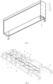
- Fig. 1 shows an axonometric view from the bottom of the facade blind box with the side panel and guides mounted in the construction opening
- Fig. 2 shows an axonometric view of the side panel
- Fig. 3 a frontal view from the side of the box hollow
- Fig. 4 and Fig. 5 shows a view of the panel from the sides.
- the side panel is produced in a form of a plate comprising at the internal box side a plurality of protruding over the plate and permanently connected therewith mounting, setting and guiding elements in a form of guides creating a slot tapering in the upper zone.
- the mounting elements in a form of pins with openings and the setting elements are grouped in subsequent and interconnected modules (1, 1', 1", 1"'). Between particular modules is made a recess 2.
- the recess provides easy separation of a module or a group of modules unnecessary for the selected height of the box.
- the panel may be adjusted to the boxes of four heights (200, 240, 300 i 350 mm).
- the depth of the boxes is 140 mm which provides correct use of the shutters of the most commonly used lamella profiles C-80 and Z-90 of the lamella width 80 mm and 90 mm respectively.
- the panel comprises two bolts 3 deployed beyond the rectangle of the plate and located at the left and right side of the panel.
- the side panel plays, located at the right or left side of the facade blind box, one of the bolts 3 is removed as it is unnecessary.
- Not removed bolts 3 of both side panels are from the top inserted into, respectively, right and left guide maintaining the facade box in the given working position.
- the guides are the sections mounted to the construction opening, and the internal shape thereof corresponds to the shape of the bolt 3, for sliding the box from the top and in order to hold the box.
- each module On the surface of the plate from the side of the box each module comprises symmetrical pins 4 with openings in the number preferably four pieces for screws mounting the box sub-elements.
- the screws used for mounting are self-drilling screws ⁇ 5 mm.
- the pins at the plate are widened to improve mechanical resistance of the pin and panel plate connection.
- profile setting elements 5 in a shape of repeatedly and alternately bent at a right angle flatbar, which are used to position and support the box elements.
- the guiding elements in a form of two guides 6 creating a tapering in the upper zone slot. The role thereof is positioning the shutter curtain and even guiding thereof.
- a plurality of intersecting reinforcing ribs near the surface of the side panel plate are formed a plurality of intersecting reinforcing ribs. The role of said ribs is to stiffen the panel plate preferably produced by plastic injection.
Landscapes
- Engineering & Computer Science (AREA)
- Structural Engineering (AREA)
- Architecture (AREA)
- Civil Engineering (AREA)
- Curtains And Furnishings For Windows Or Doors (AREA)
- Blinds (AREA)
Abstract
Description
- The present invention provides a side panel used as a structural element of a facade blind box.
- A facade blind box is produced in a form of a C-shaped profile of the length corresponding to the width of the window or door opening. At the ends of the box, at both sides side panels are mounted. The panels close the facade box at both sides.
- It is know from the utility model
DE202017000324 andDE202017000323 a side panel for an inbox of a curtain, in particular a window curtain such as a Roman blind or the like, with the interior thereof facing the inbox and the edges thereof placed at the internal side towards the base plate. At the internal side in the side panel are arranged the supporting elements of the blind characterized in that the distance between the cap edge and the edge of the external base plate in the thickness dimension of the cover plates provides that the cover plates form long sides of the inbox and that the cap edge is discontinued with recesses. The side panels are designed to be suitable for various inboxes and various shutter installation conditions. A set of a plurality of various side panels allows to prepare various sets thereof and to store in a warehouse in different versions for easy use in the future. - Problematic in prior art solutions is very limited versatility of the employed side panels which are commonly made from cast metal and cannot be adjusted and used for different heights of facade boxes. There is no option that one element of the side panel be used for both left and right side of the facade box.
- Another inconvenience in the prior art solutions is the need in many cases to mount the box to the adjacent masonry elements in the installation place. Said systems do not always provide self-supporting when the guides can overtake the function to attach the box. The guides are properly and on the entire length attached to the wall, or window or door frame, and due to that to use the guides to mount the blind box is deliberate.
- The subject of the present invention is a side panel for a facade blind box in a form of a plate comprising at the internal box side a plurality of protruding over the plate and permanently connected therewith mounting, setting and guiding elements in a form of guides creating a slot tapering in the upper zone. The mounting elements in a form of pins with openings and the setting elements are grouped in subsequent and interconnected modules. Between particular modules is made a recess for easy separation of unnecessary modules. In the lower section the side panel comprises two bolts deployed beyond the side panel plate and located at the left and right side of the panel. One of the bolts, similarly to the unnecessary modules, can be removed during box installation.
- Such designed side panel, when appropriate sheets are used making up the box and with an appropriate guide, makes the whole structure a self-supporting system. It is not necessary to additionally attach the facade blind box to the facade or lintel. The side panel shifts the weight of the facade blind attached thereto onto the guides inserted in the mounting bolt.
- The subject of the present invention is presented in the drawing where
Fig. 1 shows an axonometric view from the bottom of the facade blind box with the side panel and guides mounted in the construction opening,Fig. 2 shows an axonometric view of the side panel,Fig. 3 a frontal view from the side of the box hollow, andFig. 4 andFig. 5 shows a view of the panel from the sides. - The side panel is produced in a form of a plate comprising at the internal box side a plurality of protruding over the plate and permanently connected therewith mounting, setting and guiding elements in a form of guides creating a slot tapering in the upper zone. The mounting elements in a form of pins with openings and the setting elements are grouped in subsequent and interconnected modules (1, 1', 1", 1"'). Between particular modules is made a
recess 2. The recess provides easy separation of a module or a group of modules unnecessary for the selected height of the box. The panel may be adjusted to the boxes of four heights (200, 240, 300 i 350 mm). In all the cases, the depth of the boxes is 140 mm which provides correct use of the shutters of the most commonly used lamella profiles C-80 and Z-90 of the lamella width 80 mm and 90 mm respectively. In the lower section the panel comprises twobolts 3 deployed beyond the rectangle of the plate and located at the left and right side of the panel. Depending on the role the side panel plays, located at the right or left side of the facade blind box, one of thebolts 3 is removed as it is unnecessary. Not removedbolts 3 of both side panels are from the top inserted into, respectively, right and left guide maintaining the facade box in the given working position. The guides are the sections mounted to the construction opening, and the internal shape thereof corresponds to the shape of thebolt 3, for sliding the box from the top and in order to hold the box. - On the surface of the plate from the side of the box each module comprises
symmetrical pins 4 with openings in the number preferably four pieces for screws mounting the box sub-elements. The screws used for mounting are self-drilling screws ø 5 mm. - The pins at the plate are widened to improve mechanical resistance of the pin and panel plate connection. Moreover, over the pins in each module are located
profile setting elements 5 in a shape of repeatedly and alternately bent at a right angle flatbar, which are used to position and support the box elements. In the central section of the modules, between the pairs of pins and setting elements are made the guiding elements in a form of twoguides 6 creating a tapering in the upper zone slot. The role thereof is positioning the shutter curtain and even guiding thereof. Moreover, near the surface of the side panel plate are formed a plurality of intersecting reinforcing ribs. The role of said ribs is to stiffen the panel plate preferably produced by plastic injection.
Claims (1)
- side panel of a facade blind box in a form of a plate comprising at the internal box side a plurality of protruding over the plate and permanently connected therewith mounting, setting and guiding elements in a form of guides creating a slot tapering in the upper zone characterized in that the mounting elements in a form of pins (4) with openings and setting elements (5) are grouped in subsequent and interconnected modules (1, 1', 1", 1"'), and between particular modules is made a recess (2), and in the lower section the side panel comprising two bolts (3) deployed beyond the lateral panel plate and located at the left and right side of the panel.
Priority Applications (1)
| Application Number | Priority Date | Filing Date | Title |
|---|---|---|---|
| EP22184347.7A EP4306765B1 (en) | 2022-07-12 | 2022-07-12 | Side panel for facade blind box |
Applications Claiming Priority (1)
| Application Number | Priority Date | Filing Date | Title |
|---|---|---|---|
| EP22184347.7A EP4306765B1 (en) | 2022-07-12 | 2022-07-12 | Side panel for facade blind box |
Publications (3)
| Publication Number | Publication Date |
|---|---|
| EP4306765A1 true EP4306765A1 (en) | 2024-01-17 |
| EP4306765C0 EP4306765C0 (en) | 2025-02-26 |
| EP4306765B1 EP4306765B1 (en) | 2025-02-26 |
Family
ID=83049778
Family Applications (1)
| Application Number | Title | Priority Date | Filing Date |
|---|---|---|---|
| EP22184347.7A Active EP4306765B1 (en) | 2022-07-12 | 2022-07-12 | Side panel for facade blind box |
Country Status (1)
| Country | Link |
|---|---|
| EP (1) | EP4306765B1 (en) |
Citations (2)
| Publication number | Priority date | Publication date | Assignee | Title |
|---|---|---|---|---|
| DE202017000323U1 (en) | 2017-01-13 | 2017-03-06 | Alukon Kg | Blend cap with a fixing element for a guide profile |
| DE202017000324U1 (en) | 2017-01-13 | 2017-03-06 | Alukon Kg | Blend cap for a receiving box of a Rafflamellenstores |
-
2022
- 2022-07-12 EP EP22184347.7A patent/EP4306765B1/en active Active
Patent Citations (2)
| Publication number | Priority date | Publication date | Assignee | Title |
|---|---|---|---|---|
| DE202017000323U1 (en) | 2017-01-13 | 2017-03-06 | Alukon Kg | Blend cap with a fixing element for a guide profile |
| DE202017000324U1 (en) | 2017-01-13 | 2017-03-06 | Alukon Kg | Blend cap for a receiving box of a Rafflamellenstores |
Also Published As
| Publication number | Publication date |
|---|---|
| EP4306765C0 (en) | 2025-02-26 |
| EP4306765B1 (en) | 2025-02-26 |
Similar Documents
| Publication | Publication Date | Title |
|---|---|---|
| EP3802982B1 (en) | Building panel adapted to be mounted at a ceiling or wall of a room and method of manufacturing such building panel | |
| DE202013003496U1 (en) | Fastening element for fastening solar modules to a sloping roof surface | |
| US20060027345A1 (en) | Colonial style pressure vent hurricane shutter | |
| DE10056797B4 (en) | Butt joint element for facade panels | |
| EP4306765B1 (en) | Side panel for facade blind box | |
| DE3443931C2 (en) | ||
| US7866107B2 (en) | Cladding element for constructing building facades | |
| RU2609503C1 (en) | Facade cladding system using metal cassettes | |
| US20250290313A1 (en) | Mounting element for an installation of a runner rail in a drywall system of a sliding door construction and method for mounting a runner rail | |
| EP3214236A1 (en) | Kit for making a panel structure for an external side wall or a covering of a building, and building provided with such panel structure | |
| PL74267Y1 (en) | Side wall of the box for facade blinds | |
| RU2009100943A (en) | DESIGN FOR DIVIDING SPACES | |
| EP2947237A1 (en) | Panel securing mechanism for a game court enclosure | |
| EP3635191B1 (en) | A construction system for wall cladding | |
| US3289376A (en) | Grille or screen | |
| DE3921922C2 (en) | ||
| RU231637U1 (en) | Internal support stand for organizing fences | |
| DE102005043079A1 (en) | window | |
| GB2568260A (en) | Wall panel and associated apparatus | |
| SK19802000A3 (en) | Material handling gate | |
| EP2551421A1 (en) | A photovoltaic module which can be installed on a vertical and/or inclined wall | |
| RU231625U1 (en) | Internal support stand for organizing fences | |
| RU223991U1 (en) | Support post for the suspension system of the building facade for installing facing lamellas on the side | |
| CN219034567U (en) | Shutter device with waterproof structure | |
| EP4119762B1 (en) | Assembly of a screen device and fastening means for fastening a screen casing of this screen device |
Legal Events
| Date | Code | Title | Description |
|---|---|---|---|
| PUAI | Public reference made under article 153(3) epc to a published international application that has entered the european phase |
Free format text: ORIGINAL CODE: 0009012 |
|
| STAA | Information on the status of an ep patent application or granted ep patent |
Free format text: STATUS: THE APPLICATION HAS BEEN PUBLISHED |
|
| AK | Designated contracting states |
Kind code of ref document: A1 Designated state(s): AL AT BE BG CH CY CZ DE DK EE ES FI FR GB GR HR HU IE IS IT LI LT LU LV MC MK MT NL NO PL PT RO RS SE SI SK SM TR |
|
| RBV | Designated contracting states (corrected) |
Designated state(s): AL AT BE BG CH CY CZ DE DK EE ES FI FR GB GR HR HU IE IS IT LI LT LU LV MC MK MT NL NO PL PT RO RS SE SI SK SM TR |
|
| STAA | Information on the status of an ep patent application or granted ep patent |
Free format text: STATUS: REQUEST FOR EXAMINATION WAS MADE |
|
| 17P | Request for examination filed |
Effective date: 20240528 |
|
| GRAP | Despatch of communication of intention to grant a patent |
Free format text: ORIGINAL CODE: EPIDOSNIGR1 |
|
| STAA | Information on the status of an ep patent application or granted ep patent |
Free format text: STATUS: GRANT OF PATENT IS INTENDED |
|
| RIC1 | Information provided on ipc code assigned before grant |
Ipc: E06B 9/42 20060101ALI20241023BHEP Ipc: E06B 9/323 20060101AFI20241023BHEP |
|
| INTG | Intention to grant announced |
Effective date: 20241031 |
|
| GRAS | Grant fee paid |
Free format text: ORIGINAL CODE: EPIDOSNIGR3 |
|
| GRAA | (expected) grant |
Free format text: ORIGINAL CODE: 0009210 |
|
| STAA | Information on the status of an ep patent application or granted ep patent |
Free format text: STATUS: THE PATENT HAS BEEN GRANTED |
|
| AK | Designated contracting states |
Kind code of ref document: B1 Designated state(s): AL AT BE BG CH CY CZ DE DK EE ES FI FR GB GR HR HU IE IS IT LI LT LU LV MC MK MT NL NO PL PT RO RS SE SI SK SM TR |
|
| REG | Reference to a national code |
Ref country code: GB Ref legal event code: FG4D |
|
| REG | Reference to a national code |
Ref country code: CH Ref legal event code: EP |
|
| REG | Reference to a national code |
Ref country code: DE Ref legal event code: R096 Ref document number: 602022011020 Country of ref document: DE |
|
| REG | Reference to a national code |
Ref country code: IE Ref legal event code: FG4D |
|
| U01 | Request for unitary effect filed |
Effective date: 20250313 |
|
| U07 | Unitary effect registered |
Designated state(s): AT BE BG DE DK EE FI FR IT LT LU LV MT NL PT RO SE SI Effective date: 20250320 |
|
| PG25 | Lapsed in a contracting state [announced via postgrant information from national office to epo] |
Ref country code: RS Free format text: LAPSE BECAUSE OF FAILURE TO SUBMIT A TRANSLATION OF THE DESCRIPTION OR TO PAY THE FEE WITHIN THE PRESCRIBED TIME-LIMIT Effective date: 20250526 |
|
| PG25 | Lapsed in a contracting state [announced via postgrant information from national office to epo] |
Ref country code: PL Free format text: LAPSE BECAUSE OF FAILURE TO SUBMIT A TRANSLATION OF THE DESCRIPTION OR TO PAY THE FEE WITHIN THE PRESCRIBED TIME-LIMIT Effective date: 20250226 |
|
| PG25 | Lapsed in a contracting state [announced via postgrant information from national office to epo] |
Ref country code: ES Free format text: LAPSE BECAUSE OF FAILURE TO SUBMIT A TRANSLATION OF THE DESCRIPTION OR TO PAY THE FEE WITHIN THE PRESCRIBED TIME-LIMIT Effective date: 20250226 |
|
| PG25 | Lapsed in a contracting state [announced via postgrant information from national office to epo] |
Ref country code: NO Free format text: LAPSE BECAUSE OF FAILURE TO SUBMIT A TRANSLATION OF THE DESCRIPTION OR TO PAY THE FEE WITHIN THE PRESCRIBED TIME-LIMIT Effective date: 20250526 Ref country code: IS Free format text: LAPSE BECAUSE OF FAILURE TO SUBMIT A TRANSLATION OF THE DESCRIPTION OR TO PAY THE FEE WITHIN THE PRESCRIBED TIME-LIMIT Effective date: 20250626 |
|
| PG25 | Lapsed in a contracting state [announced via postgrant information from national office to epo] |
Ref country code: HR Free format text: LAPSE BECAUSE OF FAILURE TO SUBMIT A TRANSLATION OF THE DESCRIPTION OR TO PAY THE FEE WITHIN THE PRESCRIBED TIME-LIMIT Effective date: 20250226 |
|
| PG25 | Lapsed in a contracting state [announced via postgrant information from national office to epo] |
Ref country code: GR Free format text: LAPSE BECAUSE OF FAILURE TO SUBMIT A TRANSLATION OF THE DESCRIPTION OR TO PAY THE FEE WITHIN THE PRESCRIBED TIME-LIMIT Effective date: 20250527 |
|
| U20 | Renewal fee for the european patent with unitary effect paid |
Year of fee payment: 4 Effective date: 20250728 |
|
| PG25 | Lapsed in a contracting state [announced via postgrant information from national office to epo] |
Ref country code: SM Free format text: LAPSE BECAUSE OF FAILURE TO SUBMIT A TRANSLATION OF THE DESCRIPTION OR TO PAY THE FEE WITHIN THE PRESCRIBED TIME-LIMIT Effective date: 20250226 |
|
| PG25 | Lapsed in a contracting state [announced via postgrant information from national office to epo] |
Ref country code: CZ Free format text: LAPSE BECAUSE OF FAILURE TO SUBMIT A TRANSLATION OF THE DESCRIPTION OR TO PAY THE FEE WITHIN THE PRESCRIBED TIME-LIMIT Effective date: 20250226 |
|
| PG25 | Lapsed in a contracting state [announced via postgrant information from national office to epo] |
Ref country code: SK Free format text: LAPSE BECAUSE OF FAILURE TO SUBMIT A TRANSLATION OF THE DESCRIPTION OR TO PAY THE FEE WITHIN THE PRESCRIBED TIME-LIMIT Effective date: 20250226 |
|
| PLBE | No opposition filed within time limit |
Free format text: ORIGINAL CODE: 0009261 |
|
| STAA | Information on the status of an ep patent application or granted ep patent |
Free format text: STATUS: NO OPPOSITION FILED WITHIN TIME LIMIT |
|
| REG | Reference to a national code |
Ref country code: CH Ref legal event code: L10 Free format text: ST27 STATUS EVENT CODE: U-0-0-L10-L00 (AS PROVIDED BY THE NATIONAL OFFICE) Effective date: 20260107 |
|
| 26N | No opposition filed |
Effective date: 20251127 |
|
| REG | Reference to a national code |
Ref country code: CH Ref legal event code: H13 Free format text: ST27 STATUS EVENT CODE: U-0-0-H10-H13 (AS PROVIDED BY THE NATIONAL OFFICE) Effective date: 20260224 |
|
| PG25 | Lapsed in a contracting state [announced via postgrant information from national office to epo] |
Ref country code: CH Free format text: LAPSE BECAUSE OF NON-PAYMENT OF DUE FEES Effective date: 20250731 |
|
| PG25 | Lapsed in a contracting state [announced via postgrant information from national office to epo] |
Ref country code: IE Free format text: LAPSE BECAUSE OF NON-PAYMENT OF DUE FEES Effective date: 20250712 |
|
| PG25 | Lapsed in a contracting state [announced via postgrant information from national office to epo] |
Ref country code: MC Free format text: LAPSE BECAUSE OF FAILURE TO SUBMIT A TRANSLATION OF THE DESCRIPTION OR TO PAY THE FEE WITHIN THE PRESCRIBED TIME-LIMIT Effective date: 20250226 |
|
| PG25 | Lapsed in a contracting state [announced via postgrant information from national office to epo] |
Ref country code: CY Free format text: LAPSE BECAUSE OF FAILURE TO SUBMIT A TRANSLATION OF THE DESCRIPTION OR TO PAY THE FEE WITHIN THE PRESCRIBED TIME-LIMIT Effective date: 20250226 |