EP4306738A1 - Panel manufacturing device, panel manufacturing method, and panel - Google Patents
Panel manufacturing device, panel manufacturing method, and panel Download PDFInfo
- Publication number
- EP4306738A1 EP4306738A1 EP22787834.5A EP22787834A EP4306738A1 EP 4306738 A1 EP4306738 A1 EP 4306738A1 EP 22787834 A EP22787834 A EP 22787834A EP 4306738 A1 EP4306738 A1 EP 4306738A1
- Authority
- EP
- European Patent Office
- Prior art keywords
- faceplate
- core member
- panel
- joined
- pressurizing
- Prior art date
- Legal status (The legal status is an assumption and is not a legal conclusion. Google has not performed a legal analysis and makes no representation as to the accuracy of the status listed.)
- Pending
Links
Images



Classifications
-
- B—PERFORMING OPERATIONS; TRANSPORTING
- B29—WORKING OF PLASTICS; WORKING OF SUBSTANCES IN A PLASTIC STATE IN GENERAL
- B29C—SHAPING OR JOINING OF PLASTICS; SHAPING OF MATERIAL IN A PLASTIC STATE, NOT OTHERWISE PROVIDED FOR; AFTER-TREATMENT OF THE SHAPED PRODUCTS, e.g. REPAIRING
- B29C66/00—General aspects of processes or apparatus for joining preformed parts
- B29C66/70—General aspects of processes or apparatus for joining preformed parts characterised by the composition, physical properties or the structure of the material of the parts to be joined; Joining with non-plastics material
- B29C66/73—General aspects of processes or apparatus for joining preformed parts characterised by the composition, physical properties or the structure of the material of the parts to be joined; Joining with non-plastics material characterised by the intensive physical properties of the material of the parts to be joined, by the optical properties of the material of the parts to be joined, by the extensive physical properties of the parts to be joined, by the state of the material of the parts to be joined or by the material of the parts to be joined being a thermoplastic or a thermoset
- B29C66/739—General aspects of processes or apparatus for joining preformed parts characterised by the composition, physical properties or the structure of the material of the parts to be joined; Joining with non-plastics material characterised by the intensive physical properties of the material of the parts to be joined, by the optical properties of the material of the parts to be joined, by the extensive physical properties of the parts to be joined, by the state of the material of the parts to be joined or by the material of the parts to be joined being a thermoplastic or a thermoset characterised by the material of the parts to be joined being a thermoplastic or a thermoset
- B29C66/7392—General aspects of processes or apparatus for joining preformed parts characterised by the composition, physical properties or the structure of the material of the parts to be joined; Joining with non-plastics material characterised by the intensive physical properties of the material of the parts to be joined, by the optical properties of the material of the parts to be joined, by the extensive physical properties of the parts to be joined, by the state of the material of the parts to be joined or by the material of the parts to be joined being a thermoplastic or a thermoset characterised by the material of the parts to be joined being a thermoplastic or a thermoset characterised by the material of at least one of the parts being a thermoplastic
- B29C66/73921—General aspects of processes or apparatus for joining preformed parts characterised by the composition, physical properties or the structure of the material of the parts to be joined; Joining with non-plastics material characterised by the intensive physical properties of the material of the parts to be joined, by the optical properties of the material of the parts to be joined, by the extensive physical properties of the parts to be joined, by the state of the material of the parts to be joined or by the material of the parts to be joined being a thermoplastic or a thermoset characterised by the material of the parts to be joined being a thermoplastic or a thermoset characterised by the material of at least one of the parts being a thermoplastic characterised by the materials of both parts being thermoplastics
-
- E—FIXED CONSTRUCTIONS
- E04—BUILDING
- E04C—STRUCTURAL ELEMENTS; BUILDING MATERIALS
- E04C2/00—Building elements of relatively thin form for the construction of parts of buildings, e.g. sheet materials, slabs, or panels
- E04C2/02—Building elements of relatively thin form for the construction of parts of buildings, e.g. sheet materials, slabs, or panels characterised by specified materials
- E04C2/10—Building elements of relatively thin form for the construction of parts of buildings, e.g. sheet materials, slabs, or panels characterised by specified materials of wood, fibres, chips, vegetable stems, or the like; of plastics; of foamed products
- E04C2/20—Building elements of relatively thin form for the construction of parts of buildings, e.g. sheet materials, slabs, or panels characterised by specified materials of wood, fibres, chips, vegetable stems, or the like; of plastics; of foamed products of plastics
-
- B—PERFORMING OPERATIONS; TRANSPORTING
- B29—WORKING OF PLASTICS; WORKING OF SUBSTANCES IN A PLASTIC STATE IN GENERAL
- B29C—SHAPING OR JOINING OF PLASTICS; SHAPING OF MATERIAL IN A PLASTIC STATE, NOT OTHERWISE PROVIDED FOR; AFTER-TREATMENT OF THE SHAPED PRODUCTS, e.g. REPAIRING
- B29C53/00—Shaping by bending, folding, twisting, straightening or flattening; Apparatus therefor
- B29C53/22—Corrugating
- B29C53/24—Corrugating of plates or sheets
-
- B—PERFORMING OPERATIONS; TRANSPORTING
- B29—WORKING OF PLASTICS; WORKING OF SUBSTANCES IN A PLASTIC STATE IN GENERAL
- B29C—SHAPING OR JOINING OF PLASTICS; SHAPING OF MATERIAL IN A PLASTIC STATE, NOT OTHERWISE PROVIDED FOR; AFTER-TREATMENT OF THE SHAPED PRODUCTS, e.g. REPAIRING
- B29C65/00—Joining or sealing of preformed parts, e.g. welding of plastics materials; Apparatus therefor
- B29C65/02—Joining or sealing of preformed parts, e.g. welding of plastics materials; Apparatus therefor by heating, with or without pressure
- B29C65/08—Joining or sealing of preformed parts, e.g. welding of plastics materials; Apparatus therefor by heating, with or without pressure using ultrasonic vibrations
-
- B—PERFORMING OPERATIONS; TRANSPORTING
- B29—WORKING OF PLASTICS; WORKING OF SUBSTANCES IN A PLASTIC STATE IN GENERAL
- B29C—SHAPING OR JOINING OF PLASTICS; SHAPING OF MATERIAL IN A PLASTIC STATE, NOT OTHERWISE PROVIDED FOR; AFTER-TREATMENT OF THE SHAPED PRODUCTS, e.g. REPAIRING
- B29C65/00—Joining or sealing of preformed parts, e.g. welding of plastics materials; Apparatus therefor
- B29C65/02—Joining or sealing of preformed parts, e.g. welding of plastics materials; Apparatus therefor by heating, with or without pressure
- B29C65/08—Joining or sealing of preformed parts, e.g. welding of plastics materials; Apparatus therefor by heating, with or without pressure using ultrasonic vibrations
- B29C65/083—Joining or sealing of preformed parts, e.g. welding of plastics materials; Apparatus therefor by heating, with or without pressure using ultrasonic vibrations using a rotary sonotrode or a rotary anvil
- B29C65/086—Joining or sealing of preformed parts, e.g. welding of plastics materials; Apparatus therefor by heating, with or without pressure using ultrasonic vibrations using a rotary sonotrode or a rotary anvil using a rotary anvil
-
- B—PERFORMING OPERATIONS; TRANSPORTING
- B29—WORKING OF PLASTICS; WORKING OF SUBSTANCES IN A PLASTIC STATE IN GENERAL
- B29C—SHAPING OR JOINING OF PLASTICS; SHAPING OF MATERIAL IN A PLASTIC STATE, NOT OTHERWISE PROVIDED FOR; AFTER-TREATMENT OF THE SHAPED PRODUCTS, e.g. REPAIRING
- B29C65/00—Joining or sealing of preformed parts, e.g. welding of plastics materials; Apparatus therefor
- B29C65/02—Joining or sealing of preformed parts, e.g. welding of plastics materials; Apparatus therefor by heating, with or without pressure
- B29C65/14—Joining or sealing of preformed parts, e.g. welding of plastics materials; Apparatus therefor by heating, with or without pressure using wave energy, i.e. electromagnetic radiation, or particle radiation
- B29C65/1429—Joining or sealing of preformed parts, e.g. welding of plastics materials; Apparatus therefor by heating, with or without pressure using wave energy, i.e. electromagnetic radiation, or particle radiation characterised by the way of heating the interface
- B29C65/1432—Joining or sealing of preformed parts, e.g. welding of plastics materials; Apparatus therefor by heating, with or without pressure using wave energy, i.e. electromagnetic radiation, or particle radiation characterised by the way of heating the interface direct heating of the surfaces to be joined
-
- B—PERFORMING OPERATIONS; TRANSPORTING
- B29—WORKING OF PLASTICS; WORKING OF SUBSTANCES IN A PLASTIC STATE IN GENERAL
- B29C—SHAPING OR JOINING OF PLASTICS; SHAPING OF MATERIAL IN A PLASTIC STATE, NOT OTHERWISE PROVIDED FOR; AFTER-TREATMENT OF THE SHAPED PRODUCTS, e.g. REPAIRING
- B29C65/00—Joining or sealing of preformed parts, e.g. welding of plastics materials; Apparatus therefor
- B29C65/02—Joining or sealing of preformed parts, e.g. welding of plastics materials; Apparatus therefor by heating, with or without pressure
- B29C65/14—Joining or sealing of preformed parts, e.g. welding of plastics materials; Apparatus therefor by heating, with or without pressure using wave energy, i.e. electromagnetic radiation, or particle radiation
- B29C65/16—Laser beams
-
- B—PERFORMING OPERATIONS; TRANSPORTING
- B29—WORKING OF PLASTICS; WORKING OF SUBSTANCES IN A PLASTIC STATE IN GENERAL
- B29C—SHAPING OR JOINING OF PLASTICS; SHAPING OF MATERIAL IN A PLASTIC STATE, NOT OTHERWISE PROVIDED FOR; AFTER-TREATMENT OF THE SHAPED PRODUCTS, e.g. REPAIRING
- B29C65/00—Joining or sealing of preformed parts, e.g. welding of plastics materials; Apparatus therefor
- B29C65/02—Joining or sealing of preformed parts, e.g. welding of plastics materials; Apparatus therefor by heating, with or without pressure
- B29C65/14—Joining or sealing of preformed parts, e.g. welding of plastics materials; Apparatus therefor by heating, with or without pressure using wave energy, i.e. electromagnetic radiation, or particle radiation
- B29C65/16—Laser beams
- B29C65/1629—Laser beams characterised by the way of heating the interface
- B29C65/1632—Laser beams characterised by the way of heating the interface direct heating the surfaces to be joined
-
- B—PERFORMING OPERATIONS; TRANSPORTING
- B29—WORKING OF PLASTICS; WORKING OF SUBSTANCES IN A PLASTIC STATE IN GENERAL
- B29C—SHAPING OR JOINING OF PLASTICS; SHAPING OF MATERIAL IN A PLASTIC STATE, NOT OTHERWISE PROVIDED FOR; AFTER-TREATMENT OF THE SHAPED PRODUCTS, e.g. REPAIRING
- B29C66/00—General aspects of processes or apparatus for joining preformed parts
- B29C66/01—General aspects dealing with the joint area or with the area to be joined
- B29C66/05—Particular design of joint configurations
- B29C66/10—Particular design of joint configurations particular design of the joint cross-sections
- B29C66/11—Joint cross-sections comprising a single joint-segment, i.e. one of the parts to be joined comprising a single joint-segment in the joint cross-section
- B29C66/112—Single lapped joints
- B29C66/1122—Single lap to lap joints, i.e. overlap joints
-
- B—PERFORMING OPERATIONS; TRANSPORTING
- B29—WORKING OF PLASTICS; WORKING OF SUBSTANCES IN A PLASTIC STATE IN GENERAL
- B29C—SHAPING OR JOINING OF PLASTICS; SHAPING OF MATERIAL IN A PLASTIC STATE, NOT OTHERWISE PROVIDED FOR; AFTER-TREATMENT OF THE SHAPED PRODUCTS, e.g. REPAIRING
- B29C66/00—General aspects of processes or apparatus for joining preformed parts
- B29C66/01—General aspects dealing with the joint area or with the area to be joined
- B29C66/05—Particular design of joint configurations
- B29C66/20—Particular design of joint configurations particular design of the joint lines, e.g. of the weld lines
- B29C66/21—Particular design of joint configurations particular design of the joint lines, e.g. of the weld lines said joint lines being formed by a single dot or dash or by several dots or dashes, i.e. spot joining or spot welding
-
- B—PERFORMING OPERATIONS; TRANSPORTING
- B29—WORKING OF PLASTICS; WORKING OF SUBSTANCES IN A PLASTIC STATE IN GENERAL
- B29C—SHAPING OR JOINING OF PLASTICS; SHAPING OF MATERIAL IN A PLASTIC STATE, NOT OTHERWISE PROVIDED FOR; AFTER-TREATMENT OF THE SHAPED PRODUCTS, e.g. REPAIRING
- B29C66/00—General aspects of processes or apparatus for joining preformed parts
- B29C66/40—General aspects of joining substantially flat articles, e.g. plates, sheets or web-like materials; Making flat seams in tubular or hollow articles; Joining single elements to substantially flat surfaces
- B29C66/41—Joining substantially flat articles ; Making flat seams in tubular or hollow articles
- B29C66/43—Joining a relatively small portion of the surface of said articles
- B29C66/438—Joining sheets for making hollow-walled, channelled structures or multi-tubular articles
-
- B—PERFORMING OPERATIONS; TRANSPORTING
- B29—WORKING OF PLASTICS; WORKING OF SUBSTANCES IN A PLASTIC STATE IN GENERAL
- B29C—SHAPING OR JOINING OF PLASTICS; SHAPING OF MATERIAL IN A PLASTIC STATE, NOT OTHERWISE PROVIDED FOR; AFTER-TREATMENT OF THE SHAPED PRODUCTS, e.g. REPAIRING
- B29C66/00—General aspects of processes or apparatus for joining preformed parts
- B29C66/80—General aspects of machine operations or constructions and parts thereof
- B29C66/83—General aspects of machine operations or constructions and parts thereof characterised by the movement of the joining or pressing tools
- B29C66/834—General aspects of machine operations or constructions and parts thereof characterised by the movement of the joining or pressing tools moving with the parts to be joined
- B29C66/8341—Roller, cylinder or drum types; Band or belt types; Ball types
- B29C66/83411—Roller, cylinder or drum types
-
- B—PERFORMING OPERATIONS; TRANSPORTING
- B29—WORKING OF PLASTICS; WORKING OF SUBSTANCES IN A PLASTIC STATE IN GENERAL
- B29C—SHAPING OR JOINING OF PLASTICS; SHAPING OF MATERIAL IN A PLASTIC STATE, NOT OTHERWISE PROVIDED FOR; AFTER-TREATMENT OF THE SHAPED PRODUCTS, e.g. REPAIRING
- B29C66/00—General aspects of processes or apparatus for joining preformed parts
- B29C66/80—General aspects of machine operations or constructions and parts thereof
- B29C66/83—General aspects of machine operations or constructions and parts thereof characterised by the movement of the joining or pressing tools
- B29C66/834—General aspects of machine operations or constructions and parts thereof characterised by the movement of the joining or pressing tools moving with the parts to be joined
- B29C66/8341—Roller, cylinder or drum types; Band or belt types; Ball types
- B29C66/83431—Roller, cylinder or drum types; Band or belt types; Ball types rollers, cylinders or drums cooperating with bands or belts
-
- B—PERFORMING OPERATIONS; TRANSPORTING
- B29—WORKING OF PLASTICS; WORKING OF SUBSTANCES IN A PLASTIC STATE IN GENERAL
- B29C—SHAPING OR JOINING OF PLASTICS; SHAPING OF MATERIAL IN A PLASTIC STATE, NOT OTHERWISE PROVIDED FOR; AFTER-TREATMENT OF THE SHAPED PRODUCTS, e.g. REPAIRING
- B29C69/00—Combinations of shaping techniques not provided for in a single one of main groups B29C39/00 - B29C67/00, e.g. associations of moulding and joining techniques; Apparatus therefore
-
- B—PERFORMING OPERATIONS; TRANSPORTING
- B29—WORKING OF PLASTICS; WORKING OF SUBSTANCES IN A PLASTIC STATE IN GENERAL
- B29C—SHAPING OR JOINING OF PLASTICS; SHAPING OF MATERIAL IN A PLASTIC STATE, NOT OTHERWISE PROVIDED FOR; AFTER-TREATMENT OF THE SHAPED PRODUCTS, e.g. REPAIRING
- B29C66/00—General aspects of processes or apparatus for joining preformed parts
- B29C66/70—General aspects of processes or apparatus for joining preformed parts characterised by the composition, physical properties or the structure of the material of the parts to be joined; Joining with non-plastics material
- B29C66/72—General aspects of processes or apparatus for joining preformed parts characterised by the composition, physical properties or the structure of the material of the parts to be joined; Joining with non-plastics material characterised by the structure of the material of the parts to be joined
- B29C66/721—Fibre-reinforced materials
-
- B—PERFORMING OPERATIONS; TRANSPORTING
- B29—WORKING OF PLASTICS; WORKING OF SUBSTANCES IN A PLASTIC STATE IN GENERAL
- B29L—INDEXING SCHEME ASSOCIATED WITH SUBCLASS B29C, RELATING TO PARTICULAR ARTICLES
- B29L2024/00—Articles with hollow walls
- B29L2024/003—Articles with hollow walls comprising corrugated cores
-
- B—PERFORMING OPERATIONS; TRANSPORTING
- B29—WORKING OF PLASTICS; WORKING OF SUBSTANCES IN A PLASTIC STATE IN GENERAL
- B29L—INDEXING SCHEME ASSOCIATED WITH SUBCLASS B29C, RELATING TO PARTICULAR ARTICLES
- B29L2031/00—Other particular articles
- B29L2031/737—Articles provided with holes, e.g. grids, sieves
Definitions
- the present disclosure relates to a panel manufacturing device, a panel manufacturing method, and a panel.
- a method of manufacturing a composite sheet in which a first sheet and a second sheet that are overlapped with each other are fused by ultrasonic vibration (refer to, for example, PTL 1).
- the first sheet is formed into a corrugated shape by a first roll and is fused to the second sheet having a plate shape.
- An example of a panel such as the composite sheet includes a so-called sandwich panel in which a corrugated core member is disposed between two faceplates.
- the core member serving as the first sheet is fused with the faceplate on one side serving as the second sheet to manufacture the composite sheet.
- the fusion between the panel such as the composite sheet and the faceplate on the other side there is room for improvement.
- An object of the present disclosure is to provide a panel manufacturing device, a panel manufacturing method, and a panel capable of suitably manufacturing a panel composed of two faceplates and a core member.
- a panel manufacturing device of the present disclosure includes a transfer part that transfers, in a transfer direction, a panel having a core member that includes a thermoplastic resin and is formed in a corrugated shape and a first faceplate that includes a thermoplastic resin, is formed in a plate shape, and is joined to a surface on one side of the core member, a supply part that supplies, toward a surface on the other side of the core member, a second faceplate that includes a thermoplastic resin and is formed in a plate shape, and a joining part that joins the core member and the second faceplate to form a joined part, in which the first faceplate has a plurality of through-holes formed through the first faceplate for access to the core member, and the joining part forms the joined part via the through-hole of the first faceplate.
- a panel manufacturing method includes a step of transferring, in a transfer direction, a panel having a core member that includes a thermoplastic resin and is formed in a corrugated shape and a first faceplate that includes a thermoplastic resin, is formed in a plate shape, and is joined to a surface on one side of the core member, a step of supplying, toward a surface on the other side of the core member, a second faceplate that includes a thermoplastic resin and is formed in a plate shape, and a step of joining the core member and the second faceplate to form a joined part, in which the first faceplate has a plurality of through-holes formed through the first faceplate for access to the core member, and the joined part is formed via the through-hole of the first faceplate in the step of forming the joined part.
- a panel of the present disclosure includes a core member that includes a thermoplastic resin and is formed in a corrugated shape, a first faceplate that includes a thermoplastic resin, is formed in a plate shape, and is joined to a surface on one side of the core member, and a second faceplate that includes a thermoplastic resin, is formed in a plate shape, and is joined to a surface on the other side of the core member, in which the first faceplate has a plurality of through-holes formed through the first faceplate for access to the core member, and the second faceplate has a plurality of joined parts that are provided in correspondence with the plurality of through-holes and are formed by the joining of the second faceplate to the core member.
- a panel composed of two faceplates and a core member.
- a panel manufacturing device 10 In a panel manufacturing device 10 according to a first embodiment, faceplates 6 and 7 having a plate shape are joined to both surfaces of a core member 5 having a corrugated shape to manufacture a sheet-shaped sandwich panel (hereinafter, simply referred to as panel 1). Prior to the description of the panel manufacturing device 10, the panel 1 will be described.
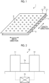
- Fig. 1 is a perspective view of the panel according to the first embodiment.
- the panel 1 is a sheet-shaped panel that is a flat plate extending in a width direction and a length direction.
- the length direction of the panel 1 is a transfer direction in the panel manufacturing device 10 described below.
- the panel 1 includes a core member 5, a first faceplate 6, and a second faceplate 7.
- the core member 5, the first faceplate 6, and the second faceplate 7 are configured to include a thermoplastic resin.
- the core member 5, the first faceplate 6, and the second faceplate 7 may be a composite material containing a reinforcing fiber in addition to the thermoplastic resin.
- the thermoplastic resins used in the core member 5, the first faceplate 6, and the second faceplate 7 may be different types of thermoplastic resins.
- the core member 5 is formed in the corrugated shape.
- the core member 5 has a wave shape in which peaks and valleys are alternately and continuously formed in the length direction, and is formed such that tops of the peaks and bottom portions of the valleys extend in the width direction.
- the corrugated shape is not particularly limited to the above-mentioned shape, and may be, for example, an embossed shape in which undulations are formed in a staggered manner. That is, any shape may be employed as long as the shape can be continuously formed in the transfer direction in the panel manufacturing device 10 described below.
- the first faceplate 6 is joined to a surface on one side (upper side in Fig. 1 ) of the core member 5.
- the first faceplate 6 is formed in a plate shape.
- the first faceplate 6 is joined to the tops of the peaks of the core member 5, while being separated from the bottom portions of the valleys of the core member 5.
- the first faceplate 6 has a plurality of through-holes 8.
- the plurality of through-holes 8 are formed through and are holes for accessing the core member 5 from the outside via the first faceplate 6.
- the through-hole 8 is, for example, a circular opening (round hole).
- the through-hole 8 may be a rectangular opening (slit) and is not particularly limited.
- the plurality of through-holes 8 are arranged in a grid pattern in the length direction and the width direction. Specifically, the plurality of through-holes 8 are provided side by side along the width direction at a predetermined spacing. Further, the plurality of through-holes 8 are provided at positions facing the bottom portions of the valley
- the second faceplate 7 is joined to a surface on the other side (lower side in Fig. 1 ) of the core member 5.
- the second faceplate 7 is formed in a plate shape.
- the second faceplate 7 is joined to the bottom portions of the valleys of the core member 5, while being separated from the tops of the peaks of the core member 5.
- the second faceplate 7 is provided with a welding part 9 as a joined part, which is a portion to be joined to the core member 5.
- the core member 5 and the first faceplate 6 are first joined to form a panel 1a, and then the panel 1a and the second faceplate 7 are joined to form the sandwich panel shown in Fig. 1 .
- the plurality of through-holes 8 provided in the panel 1 may be holes that add sound absorbing performance to the panel 1. That is, the plurality of through-holes 8 allow the sound incident on the panel 1 to pass toward the inside of the panel 1 and reflect the sound inside the panel 1 to absorb the sound. Further, the plurality of through-holes 8 may make the rigidity of the first faceplate 6 lower than the rigidity of the second faceplate 7. In a case where the rigidity of the first faceplate 6 before the through-hole 8 is provided is the same as the rigidity of the second faceplate 7, the providing of the plurality of through-holes 8 results in the decrease in the rigidity of the first faceplate 6. Therefore, in a case where the panel 1 is deformed, the panel 1 is easily deformed and processed with a first faceplate 6 side as a valley fold and a second faceplate 7 side as a mountain fold.
- Fig. 2 is a schematic configuration diagram representing a panel manufacturing device according to the first embodiment.
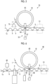
- Fig. 3 is a schematic configuration diagram representing a single facer.
- Fig. 4 is a schematic configuration diagram representing a double facer.
- the panel manufacturing device 10 includes a single facer 11, a double facer 12, and a control device 15.
- the single facer 11 is a device that joins the core member 5 and the first faceplate 6 to form the panel 1a.
- the single facer 11 includes a belt roll 41, a tension roll 42, a pressurizing belt 43, an upper corrugating roll 44, and a lower corrugating roll 45.
- the belt roll 41 can be driven and rotated by a drive device (not shown).
- the tension roll 42 is rotatably supported at a predetermined spacing from the belt roll 41.
- the pressurizing belt 43 is an endless belt and is wound around the belt roll 41 and the tension roll 42.
- the upper corrugating roll 44 can be driven and rotated by a drive device (not shown), and the outer peripheral surface thereof is formed in a wave shape.
- the upper corrugating roll 44 is disposed below the pressurizing belt 43 in a vertical direction between the belt roll 41 and the tension roll 42, and the wave-shaped outer peripheral surface comes into contact with a lower surface of the pressurizing belt 43 in a pressurized state.
- the lower corrugating roll 45 has the outer peripheral surface formed in a wave shape and is engaged with the outer peripheral surface of the upper corrugating roll 44 below the upper corrugating roll 44 in a vertical direction.
- the first faceplate 6 supplied to the single facer 11 is wound around a guide roller 47 on an upstream side and then wound around a guide roller 46 on a downstream side. Thereafter, together with the pressurizing belt 43 guided by the belt roll 41, the first faceplate 6 is sandwiched between the pressurizing belt 43 and the upper corrugating roll 44 and is pressurized.
- the plate-shaped core member 5 before shaping is shaped into a wave shape at the engaging portion between the upper corrugating roll 44 and the lower corrugating roll 45, and then guided by the upper corrugating roll 44 to be supplied between the pressurizing belt 43 and the upper corrugating roll 44.
- the single facer 11 includes a joining device (not shown) that joins the first faceplate 6 and the core member 5.
- the joining device melts the top of the peak of the core member 5 by heating.
- the core member 5 whose top of the peak is melted is transferred between the pressurizing belt 43 and the upper corrugating roll 44 and is pressurized, together with the first faceplate 6, between the pressurizing belt 43 and the upper corrugating roll 44 to join the core member 5 and the first faceplate 6.
- the single facer 11 joins the core member 5 and the first faceplate 6 to form the panel 1a and transfers the formed panel 1a toward the double facer 12.
- the double facer 12 is a device that joins the panel 1a and the second faceplate 7 to form the panel 1 to be the sandwich panel.
- the double facer 12 includes a transfer part 51, a supply part 52, and a joining part 53.
- the transfer part 51 is a device that transfers the panel 1a in the transfer direction.
- the transfer part 51 sandwiches, from both sides, the panel 1 after the second faceplate 7 is joined to the panel 1a and delivers the panel 1 in the transfer direction to transfer the panel 1a.
- the transfer part 51 may be configured by using a plurality of transfer rollers or may be configured by using an endless belt such as the pressurizing belt 43 of the single facer 11.
- the supply part 52 is a device that supplies the second faceplate 7 toward the surface on the other side of the core member 5 of the panel 1a.
- the supply part 52 has a pair of transfer rollers 57 that sandwiches the second faceplate 7 and delivers the second faceplate 7 toward the joining part 53.
- the joining part 53 joins the core member 5 and the second faceplate 7 to form the welding part 9.
- the joining part 53 forms the welding part 9 via the plurality of through-holes 8 provided in the first faceplate 6.
- the joining part 53 includes a pressurizing part 61 and a heating part 62.
- the pressurizing part 61 is a device that pressurizes the welding part 9 and includes a receiving roller (receiving member) 65, a pressurizing rod (pressurizing member) 66, and a rod drive unit 67.
- the receiving roller 65 is in rolling contact with the outer surface of the second faceplate 7 and serves as a roller that receives the pressurization from the pressurizing rod 66.
- the receiving roller 65 may be heated by a heating source to contribute to the joining between the core member 5 and the second faceplate 7.
- the pressurizing rod 66 is a rod-shaped member that is inserted into the through-hole 8 that is the circular opening.
- the pressurizing rod 66 sandwiches and pressurizes the core member 5 and the second faceplate 7 between the pressurizing rod 66 and the receiving roller 65.
- the pressurizing rod 66 can freely move back and forth between a pressing position where the pressurizing rod 66 sandwiches the core member 5 and the second faceplate 7 and an avoiding position where the pressurizing rod 66 separates from the through-hole 8 and avoids physical interference with the panel 1a.
- a plurality of the pressurizing rods 66 are provided over the width direction and are provided in correspondence with the plurality of through-holes 8 provided side by side in the width direction.
- the rod drive unit 67 is a drive unit that moves the pressurizing rod 66 back and forth between the pressing position and the avoiding position.
- a cylinder is applied to the rod drive unit 67.
- the rod drive unit 67 is not particularly limited to the cylinder and may be any actuator.
- the rod drive unit 67 is connected to the control device 15, and the control device 15 controls the drive of the rod drive unit 67 to control the back and forth movement of the pressurizing rod 66.
- the heating part 62 is a device (vibration heating part) that imparts ultrasonic vibration to the pressurizing rod 66 to perform ultrasonic welding.
- the heating part 62 includes the pressurizing rod 66 serving as a vibrator and a vibration imparting part 68.
- the vibration imparting part 68 imparts the ultrasonic vibration to the pressurizing rod 66 that has moved to the pressing position.
- the vibration imparting part 68 imparts the vibration to the pressurizing rod 66
- the core member 5 and the second faceplate 7, which are sandwiched between the pressurizing rod 66 and the receiving roller 65 are ultrasonically welded.
- the vibration imparting part 68 is connected to the control device 15, and the control device 15 controls the vibration of the vibration imparting part 68 to control the ultrasonic welding by the pressurizing rod 66.
- the panel 1a transferred from the single facer 11 to the double facer 12 is pulled between the receiving roller 65 and the pressurizing rod 66 by the transfer part 51. Further, the second faceplate 7 supplied to the double facer 12 is supplied between the receiving roller 65 and the pressurizing rod 66 by the transfer roller 57. In this case, the second faceplate 7 is supplied to the surface on the other side of the core member 5 of the panel 1a.
- the rod drive unit 67 moves the pressurizing rod 66 from the avoiding position to the pressing position with respect to the panel 1a and the second faceplate 7 supplied between the receiving roller 65 and the pressurizing rod 66.
- the pressurizing rod 66 is inserted through the through-hole 8 and accesses the core member 5 to pressurize the bottom portion of the valley of the core member 5 of the panel 1a and the second faceplate 7.
- the vibration imparting part 68 imparts the ultrasonic vibration to the pressurizing rod 66 in a state where the pressurizing rod 66 is positioned at the pressing position, and thus the bottom portion of the valley of the core member 5 of the panel 1a and the second faceplate 7 are ultrasonically welded by the ultrasonic welding.
- the double facer 12 discharges the panel 1 obtained by joining the panel 1a and the second faceplate 7.
- the discharged panel 1 may be discharged as it is or may be cut into a single-wafer sheet, and is not particularly limited.
- the control device 15 is connected to the single facer 11 and the double facer 12 and controls the drive thereof. Specifically, in the double facer 12, the control device 15 is connected to the rod drive unit 67 and the vibration imparting part 68 and controls the pressurization operation by the pressurizing rod 66 and the ultrasonic welding by the pressurizing rod 66.
- the panel manufacturing device 10 shapes the core member 5 having the corrugated shape and joins the shaped core member 5 and the first faceplate 6 to form the panel 1a.
- the panel manufacturing device 10 transfers the formed panel 1a from the single facer 11 toward the double facer 12.
- the transfer part 51 transfers the panel 1a in the transfer direction (length direction) in the double facer 12 to supply the panel 1a toward the joining part 53.
- the transfer roller 57 of the supply part 52 supplies the second faceplate 7 toward the surface on the other side of the core member 5.
- the joining part 53 joins the panel 1a and the second faceplate 7 to form the welding part 9.
- the pressurizing rod 66 of the pressurizing part 61 of the joining part 53 is inserted into the through-hole 8 of the first faceplate 6.
- the rod drive unit 67 moves the pressurizing rod 66 to the pressing position to pressurize the core member 5 and the second faceplate 7 between the pressurizing rod 66 and the receiving roller 65. Further, in the panel manufacturing device 10, the vibration imparting part 68 imparts the ultrasonic vibration to the pressurizing rod 66 in the pressurized state to perform the ultrasonic welding.
- a panel manufacturing device 70 according to a second embodiment will be described with reference to Fig. 5 .
- Fig. 5 is a schematic configuration diagram representing a panel manufacturing device according to the second embodiment.
- the panel manufacturing device 70 of the second embodiment is provided with a heating part 72 instead of the heating part 62 (vibration imparting part 68) in the panel manufacturing device 10 of the first embodiment.
- the pressurizing part 61 and the heating part 62 of the joining part 53 are integrated.
- the pressurizing part 61 and the heating part 72 of the joining part 53 are separate bodies.
- the heating part 72 heats a surface on which the core member 5 and the second faceplate 7 face each other to raise the temperature to a temperature at which heat welding is possible.
- the heating part 72 is, for example, a heating heater, a laser, or a heating lamp, and is provided at a position on an upstream side in the transfer direction of the receiving roller 65 and the pressurizing rod 66. Further, the heating part 72 is provided in a space formed between the core member 5 and the second faceplate 7 and heats the surface on the other side of the core member 5 and the surface of the second faceplate 7 facing the core member 5.
- the core member 5 of the panel 1a and the second faceplate 7, which are heated by the heating part 72, are joined by being pressurized by the pressurizing rod 66.
- a panel manufacturing device 80 according to a third embodiment will be described with reference to Fig. 6 . Further, even in the third embodiment, in order to avoid duplicate description, the parts different from the first and second embodiments will be described, and the parts having the same configuration as those of the first and second embodiments will be described with the same reference numerals.
- Fig. 6 is a schematic configuration diagram representing a panel manufacturing device according to the third embodiment.
- the panel manufacturing device 80 of the third embodiment is provided with a heating part 82 instead of the heating part 62 (vibration imparting part 68) in the panel manufacturing device 10 of the first embodiment.
- the pressurizing part 61 and the heating part 62 of the joining part 53 are integrated.
- the pressurizing part 61 and the heating part 82 of the joining part 53 are separate bodies.
- the panel manufacturing device 80 further includes a hole processing part 84 and a shape detecting unit 85.
- the heating part 82 is a laser irradiation part that emits the laser from a side of the core member 5 via the through-hole 8 of the first faceplate 6 to heat the bottom portion of the valley of the core member 5.
- the heating part 82 is provided at a position on the upstream side in the transfer direction of the receiving roller 65 and the pressurizing rod 66, and is provided on the first faceplate 6 side.
- the heating part 82 emits the laser to pass through the through-hole 8 to heat the bottom portion of the valley of the core member 5 and heat the welding portion with the second faceplate 7.
- the hole processing part 84 is a processing device that forms the plurality of through-holes 8 in the first faceplate 6 and is, for example, a punching drill.
- the hole processing part 84 is provided at a position on an upstream side in the transfer direction of the heating part 82 and is provided on the first faceplate 6 side.
- the hole processing part 84 forms the through-hole 8 through the portion of the first faceplate 6 facing the bottom portion of the valley of the core member 5.
- the shape detecting unit 85 is a sensor that detects the corrugated shape of the core member 5.
- the shape detecting unit 85 is provided at a position on an upstream side in the transfer direction of the hole processing part 84 and is provided on a core member 5 side.
- the shape detecting unit 85 is, for example, a measurement device that is in contact with the core member 5 to mechanically measure the shape.
- the shape detecting unit 85 may measure the shape by using a laser displacement sensor or may measure the shape by capturing an image, and is not particularly limited.
- the shape detecting unit 85 is connected to the control device 15 and outputs a measurement result of the corrugated shape of the core member 5 to the control device 15.
- the control device 15 controls the hole processing part 84, the heating part 82, and the pressurizing part 61 based on the shape of the core member 5 acquired from the shape detecting unit 85. Specifically, the control device 15 controls the hole processing part 84 such that a position of the through-hole 8 formed by the hole processing part 84 faces the bottom portion of the valley of the core member 5, based on the shape of the core member 5. Further, the control device 15 controls the heating part 82 such that a position heated by the heating part 82 is the bottom portion of the valley of the core member 5, based on the shape of the core member 5. Further, the control device 15 controls the pressurizing part 61 such that a position pressurized by the pressurizing part 61 is the bottom portion of the valley of the core member 5, based on the shape of the core member 5.
- the pressurizing part 61, the heating part 82, and the hole processing part 84 are separate bodies, but a configuration in which the above parts are integrated may be used. That is, the joining part 53 may be configured to function as the pressurizing part 61, the heating part 82, and the hole processing part 84, and to be capable of performing the hole processing, the pressurization, and the heating in one operation.
- the hole processing part 84 and the shape detecting unit 85 of the third embodiment are applicable to the first embodiment and the second embodiment. That is, in the first embodiment or the second embodiment, the hole processing part 84 and the shape detecting unit 85 are provided at a position on an upstream side in the transfer direction of the joining part 53 in the double facer 12.
- the panel 1a is formed by using the first faceplate 6 having no through-hole 8 in the single facer 11, the hole processing part 84 and the shape detecting unit 85 form the plurality of through-holes 8 in the double facer 12, and then the panel 1a and the second faceplate 7 are joined to each other by the joining part 53 to form the panel 1.
- the joining part 53 may control the pressurizing part 61 based on the shape of the core member 5 acquired from the shape detecting unit 85.
- the shape detecting unit 85 of the third embodiment may be applied to the first and second embodiments.
- the pressurizing part 61 may be controlled based on the shape of the core member 5 acquired from the shape detecting unit 85.
- a panel manufacturing device 90 according to a fourth embodiment will be described with reference to Figs. 7 to 9 .
- Fig. 7 is a schematic configuration diagram representing a panel manufacturing device according to the fourth embodiment.
- Fig. 8 and Fig. 9 are explanatory diagrams representing examples of the welding part.
- the pressurizing rod 66 of the pressurizing part 61 in the panel manufacturing device 10 of the first embodiment is omitted, and the heating part 82 of the third embodiment is provided instead of the pressurizing rod 66. That is, the panel manufacturing device 90 of the fourth embodiment has a device configuration in which the core member 5 and the second faceplate 7 can be sufficiently joined by pressurization by the receiving roller 65.
- the heating part 82 is a laser irradiation part that emits the laser from a side of the core member 5 via the through-hole 8 of the first faceplate 6 to heat the bottom portion of the valley of the core member 5.
- the heating part 82 is provided at a position facing the receiving roller 65 and is provided on the first faceplate 6 side.
- the heating part 82 emits the laser to pass through the through-hole 8 to heat the bottom portion of the valley of the core member 5 and heat the welding portion with the second faceplate 7.
- a left-right direction thereof is the width direction of the panel 1.
- the welding part 9 shown in Fig. 8 is a circular spot welding part formed by the laser irradiation to correspond to the plurality of through-holes 8 that is the circular opening.
- the welding part 9 shown in Fig. 9 is a wide welding part continuous in the width direction.
- the welding part shown in Fig. 9 may be formed by diffusing the laser in the width direction, or the welding part shown in Fig. 9 may be formed by forming the plurality of through-holes 8 as a slit opening.
- the core member 5, the first faceplate 6, and the second faceplate 7, which have a continuous sheet shape, are continuously supplied.
- the core member 5, the first faceplate 6, and the second faceplate 7 may be intermittently supplied as single wafers.
- a pressurizing roller may be configured in which a plurality of pressurizing rods 66 are provided on an outer peripheral surface in a protruded manner. That is, with rotation of the pressurizing roller, the plurality of pressurizing rods 66 are inserted into the plurality of through-holes 8 to sandwich and pressurize the core member 5 and the second faceplate 7 between the pressurizing rods 66 and the receiving roller 65. Thereafter, with further rotation of the pressurizing roller, the plurality of pressurizing rods 66 after the pressurization may be retracted from the plurality of through-holes 8.
- the panel manufacturing devices 10, 70, 80, and 90, the panel manufacturing method, and the panel 1 described in the embodiments are grasped as follows, for example.
- Panel manufacturing devices 10, 70, 80, and 90 include a transfer part 51 that transfers, in a transfer direction, a panel 1a having a core member 5 that includes a thermoplastic resin and is formed in a corrugated shape and a first faceplate 6 that includes a thermoplastic resin, is formed in a plate shape, and is joined to a surface on one side of the core member 5, a supply part 52 that supplies, toward a surface on the other side of the core member 5, a second faceplate 7 that includes a thermoplastic resin and is formed in a plate shape, and a joining part 53 that joins the core member 5 and the second faceplate 7 to form a joined part (welding part 9), in which the first faceplate 6 has a plurality of through-holes 8 formed through the first faceplate 6 for access to the core member 5, and the joining part 53 forms the joined part via the through-hole 8 of the first faceplate 6.
- the core member 5 can be accessed through the through-hole 8, it is possible to appropriately join the core member 5 of the panel 1a and the second faceplate 7. Therefore, it is possible to suitably manufacture the panel 1 composed of the two faceplates 6 and 7 and the core member 5.
- the joining part 53 has a pressurizing part 61 that pressurizes the joined part
- the pressurizing part 61 includes a pressurizing member (pressurizing rod 66) that is inserted into the through-hole 8 of the first faceplate 6 to pressurize the joined part from a side of the core member 5 toward a side of the second faceplate 7, and a receiving member (receiving roller 65) that is provided on a side opposite to the panel 1a across the second faceplate 7 to receive the pressurization of the pressurizing member.
- the joining part 53 further includes a heating part 62 that heats the joined part, and the heating part 62 is a vibration heating part that imparts vibration to the pressurizing member to heat the joined part.
- the joining part 53 has heating parts 72 and 82 that heat the joined part, and the heating parts 72 and 82 are laser irradiation parts that emit a laser from a side of the core member 5 via the through-hole 8 of the first faceplate 6 to heat the joined part.
- the joining part 53 further includes a pressurizing part 61 that pressurizes the joined part, and the pressurizing part 61 sandwiches and pressurizes the panel 1a and the second faceplate 7.
- the panel 1a and the second faceplate 7 are sandwiched and pressurized by the pressurizing part 61, and thus it is possible to suitably join the panel 1a and the second faceplate 7.
- a shape detecting unit 85 that detects the corrugated shape of the core member 5 is further provided, in which the joining part 53 executes the joining of the joined part based on the corrugated shape of the core member 5 detected by the shape detecting unit 85.
- a hole processing part 84 that forms the plurality of through-holes 8 in the first faceplate 6 is further provided.
- the hole processing part 84 forms the plurality of through-holes 8 in the first faceplate 6, there is no need to prepare the first faceplate 6 in which the through-holes 8 are formed in advance.
- a shape detecting unit 85 that detects the corrugated shape of the core member 5 is further provided, in which the hole processing part 84 executes hole processing in the first faceplate 6 based on the corrugated shape of the core member 5 detected by the shape detecting unit 85.
- the hole processing can be performed based on the corrugated shape of the core member 5 detected by the shape detecting unit 85, it is possible to form the plurality of through-holes 8 at appropriate positions.
- a panel manufacturing method includes a step of transferring, in a transfer direction, a panel 1a having a core member 5 that includes a thermoplastic resin and is formed in a corrugated shape and a first faceplate 6 that includes a thermoplastic resin, is formed in a plate shape, and is joined to a surface on one side of the core member 5, a step of supplying, toward a surface on the other side of the core member 5, a second faceplate 7 that includes a thermoplastic resin and is formed in a plate shape, and a step of joining the core member 5 and the second faceplate 7 to form a joined part, in which the first faceplate 6 has a plurality of through-holes 8 formed through the first faceplate 6 for access to the core member 5, and the joined part is formed via the through-hole 8 of the first faceplate 6 in the step of forming the joined part.
- the core member 5 can be accessed through the through-hole 8, it is possible to appropriately join the core member 5 of the panel 1a and the second faceplate 7. Therefore, it is possible to suitably manufacture the panel 1 composed of the two faceplates 6 and 7 and the core member 5.
- a panel 1 according to a tenth aspect includes a core member 5 that includes a thermoplastic resin and is formed in a corrugated shape, a first faceplate 6 that includes a thermoplastic resin, is formed in a plate shape, and is joined to a surface on one side of the core member 5, and a second faceplate 7 that includes a thermoplastic resin, is formed in a plate shape, and is joined to a surface on the other side of the core member 5, in which the first faceplate 6 has a plurality of through-holes 8 formed through the first faceplate 6 for access to the core member 5, and the second faceplate 7 has a plurality of joined parts that are provided in correspondence with the plurality of through-holes 8 and are formed by the joining of the second faceplate 7 to the core member 5.
- the plurality of through-holes are holes that add sound absorbing performance.
- the plurality of through-holes 8 make rigidity of the first faceplate 6 lower than rigidity of the second faceplate 7.
Landscapes
- Engineering & Computer Science (AREA)
- Mechanical Engineering (AREA)
- Physics & Mathematics (AREA)
- Electromagnetism (AREA)
- Toxicology (AREA)
- Health & Medical Sciences (AREA)
- Architecture (AREA)
- Optics & Photonics (AREA)
- Life Sciences & Earth Sciences (AREA)
- Wood Science & Technology (AREA)
- Civil Engineering (AREA)
- Structural Engineering (AREA)
- Laminated Bodies (AREA)
- Panels For Use In Building Construction (AREA)
- Lining Or Joining Of Plastics Or The Like (AREA)
Abstract
Description
- The present disclosure relates to a panel manufacturing device, a panel manufacturing method, and a panel.
- In the related art, there is known a method of manufacturing a composite sheet in which a first sheet and a second sheet that are overlapped with each other are fused by ultrasonic vibration (refer to, for example, PTL 1). The first sheet is formed into a corrugated shape by a first roll and is fused to the second sheet having a plate shape.
- [PTL 1]
Japanese Unexamined Patent Application Publication No. 2019-188802 - An example of a panel such as the composite sheet includes a so-called sandwich panel in which a corrugated core member is disposed between two faceplates. In PTL 1, the core member serving as the first sheet is fused with the faceplate on one side serving as the second sheet to manufacture the composite sheet. On the other hand, there is no description or suggestion in PTL 1 regarding the fusion between the panel such as the composite sheet and the faceplate on the other side, and there is room for improvement.
- An object of the present disclosure is to provide a panel manufacturing device, a panel manufacturing method, and a panel capable of suitably manufacturing a panel composed of two faceplates and a core member.
- A panel manufacturing device of the present disclosure includes a transfer part that transfers, in a transfer direction, a panel having a core member that includes a thermoplastic resin and is formed in a corrugated shape and a first faceplate that includes a thermoplastic resin, is formed in a plate shape, and is joined to a surface on one side of the core member, a supply part that supplies, toward a surface on the other side of the core member, a second faceplate that includes a thermoplastic resin and is formed in a plate shape, and a joining part that joins the core member and the second faceplate to form a joined part, in which the first faceplate has a plurality of through-holes formed through the first faceplate for access to the core member, and the joining part forms the joined part via the through-hole of the first faceplate.
- A panel manufacturing method according to the present disclosure includes a step of transferring, in a transfer direction, a panel having a core member that includes a thermoplastic resin and is formed in a corrugated shape and a first faceplate that includes a thermoplastic resin, is formed in a plate shape, and is joined to a surface on one side of the core member, a step of supplying, toward a surface on the other side of the core member, a second faceplate that includes a thermoplastic resin and is formed in a plate shape, and a step of joining the core member and the second faceplate to form a joined part, in which the first faceplate has a plurality of through-holes formed through the first faceplate for access to the core member, and the joined part is formed via the through-hole of the first faceplate in the step of forming the joined part.
- A panel of the present disclosure includes a core member that includes a thermoplastic resin and is formed in a corrugated shape, a first faceplate that includes a thermoplastic resin, is formed in a plate shape, and is joined to a surface on one side of the core member, and a second faceplate that includes a thermoplastic resin, is formed in a plate shape, and is joined to a surface on the other side of the core member, in which the first faceplate has a plurality of through-holes formed through the first faceplate for access to the core member, and the second faceplate has a plurality of joined parts that are provided in correspondence with the plurality of through-holes and are formed by the joining of the second faceplate to the core member.
- According to the present disclosure, it is possible to suitably manufacture a panel composed of two faceplates and a core member.
-
-
Fig. 1 is a perspective view of a panel according to a first embodiment. -
Fig. 2 is a schematic configuration diagram representing a panel manufacturing device according to the first embodiment. -
Fig. 3 is a schematic configuration diagram representing a single facer. -
Fig. 4 is a schematic configuration diagram representing a double facer. -
Fig. 5 is a schematic configuration diagram representing a panel manufacturing device according to a second embodiment. -
Fig. 6 is a schematic configuration diagram representing a panel manufacturing device according to a third embodiment. -
Fig. 7 is a schematic configuration diagram representing a panel manufacturing device according to a fourth embodiment. -
Fig. 8 is an explanatory diagram representing an example of a welding part. -
Fig. 9 is an explanatory diagram representing an example of the welding part. - Hereinafter, an embodiment according to the present disclosure will be described in detail based on drawings. The invention is not limited to the embodiment. Further, components in the following embodiment include components that can be easily replaced by those skilled in the art or components that are substantially the same. Furthermore, the components described below can be combined as appropriate, and in a case where there are a plurality of embodiments, the respective embodiments can also be combined.
- In a
panel manufacturing device 10 according to a first embodiment,faceplates 6 and 7 having a plate shape are joined to both surfaces of acore member 5 having a corrugated shape to manufacture a sheet-shaped sandwich panel (hereinafter, simply referred to as panel 1). Prior to the description of thepanel manufacturing device 10, the panel 1 will be described. -
Fig. 1 is a perspective view of the panel according to the first embodiment. As shown inFig. 1 , the panel 1 is a sheet-shaped panel that is a flat plate extending in a width direction and a length direction. The length direction of the panel 1 is a transfer direction in thepanel manufacturing device 10 described below. The panel 1 includes acore member 5, afirst faceplate 6, and a second faceplate 7. Thecore member 5, thefirst faceplate 6, and the second faceplate 7 are configured to include a thermoplastic resin. Thecore member 5, thefirst faceplate 6, and the second faceplate 7 may be a composite material containing a reinforcing fiber in addition to the thermoplastic resin. Further, the thermoplastic resins used in thecore member 5, thefirst faceplate 6, and the second faceplate 7 may be different types of thermoplastic resins. - The
core member 5 is formed in the corrugated shape. Specifically, thecore member 5 has a wave shape in which peaks and valleys are alternately and continuously formed in the length direction, and is formed such that tops of the peaks and bottom portions of the valleys extend in the width direction. The corrugated shape is not particularly limited to the above-mentioned shape, and may be, for example, an embossed shape in which undulations are formed in a staggered manner. That is, any shape may be employed as long as the shape can be continuously formed in the transfer direction in thepanel manufacturing device 10 described below. - The
first faceplate 6 is joined to a surface on one side (upper side inFig. 1 ) of thecore member 5. Thefirst faceplate 6 is formed in a plate shape. Thefirst faceplate 6 is joined to the tops of the peaks of thecore member 5, while being separated from the bottom portions of the valleys of thecore member 5. Thefirst faceplate 6 has a plurality of through-holes 8. The plurality of through-holes 8 are formed through and are holes for accessing thecore member 5 from the outside via thefirst faceplate 6. The through-hole 8 is, for example, a circular opening (round hole). The through-hole 8 may be a rectangular opening (slit) and is not particularly limited. The plurality of through-holes 8 are arranged in a grid pattern in the length direction and the width direction. Specifically, the plurality of through-holes 8 are provided side by side along the width direction at a predetermined spacing. Further, the plurality of through-holes 8 are provided at positions facing the bottom portions of the valleys of thecore member 5 in the length direction. - The second faceplate 7 is joined to a surface on the other side (lower side in
Fig. 1 ) of thecore member 5. The second faceplate 7 is formed in a plate shape. The second faceplate 7 is joined to the bottom portions of the valleys of thecore member 5, while being separated from the tops of the peaks of thecore member 5. The second faceplate 7 is provided with awelding part 9 as a joined part, which is a portion to be joined to thecore member 5. - In the panel 1, the
core member 5 and thefirst faceplate 6 are first joined to form apanel 1a, and then thepanel 1a and the second faceplate 7 are joined to form the sandwich panel shown inFig. 1 . - Here, the plurality of through-
holes 8 provided in the panel 1 may be holes that add sound absorbing performance to the panel 1. That is, the plurality of through-holes 8 allow the sound incident on the panel 1 to pass toward the inside of the panel 1 and reflect the sound inside the panel 1 to absorb the sound. Further, the plurality of through-holes 8 may make the rigidity of thefirst faceplate 6 lower than the rigidity of the second faceplate 7. In a case where the rigidity of thefirst faceplate 6 before the through-hole 8 is provided is the same as the rigidity of the second faceplate 7, the providing of the plurality of through-holes 8 results in the decrease in the rigidity of thefirst faceplate 6. Therefore, in a case where the panel 1 is deformed, the panel 1 is easily deformed and processed with afirst faceplate 6 side as a valley fold and a second faceplate 7 side as a mountain fold. - Next, the
panel manufacturing device 10 will be described with reference toFigs. 2 to 4 .Fig. 2 is a schematic configuration diagram representing a panel manufacturing device according to the first embodiment.Fig. 3 is a schematic configuration diagram representing a single facer.Fig. 4 is a schematic configuration diagram representing a double facer. As shown inFig. 2 , thepanel manufacturing device 10 includes asingle facer 11, adouble facer 12, and acontrol device 15. - The
single facer 11 is a device that joins thecore member 5 and thefirst faceplate 6 to form thepanel 1a. Thesingle facer 11 includes abelt roll 41, atension roll 42, a pressurizingbelt 43, anupper corrugating roll 44, and alower corrugating roll 45. - The
belt roll 41 can be driven and rotated by a drive device (not shown). Thetension roll 42 is rotatably supported at a predetermined spacing from thebelt roll 41. The pressurizingbelt 43 is an endless belt and is wound around thebelt roll 41 and thetension roll 42. Theupper corrugating roll 44 can be driven and rotated by a drive device (not shown), and the outer peripheral surface thereof is formed in a wave shape. Theupper corrugating roll 44 is disposed below the pressurizingbelt 43 in a vertical direction between thebelt roll 41 and thetension roll 42, and the wave-shaped outer peripheral surface comes into contact with a lower surface of the pressurizingbelt 43 in a pressurized state. As in theupper corrugating roll 44, thelower corrugating roll 45 has the outer peripheral surface formed in a wave shape and is engaged with the outer peripheral surface of theupper corrugating roll 44 below theupper corrugating roll 44 in a vertical direction. - The
first faceplate 6 supplied to thesingle facer 11 is wound around aguide roller 47 on an upstream side and then wound around aguide roller 46 on a downstream side. Thereafter, together with the pressurizingbelt 43 guided by thebelt roll 41, thefirst faceplate 6 is sandwiched between the pressurizingbelt 43 and theupper corrugating roll 44 and is pressurized. On the other hand, the plate-shapedcore member 5 before shaping is shaped into a wave shape at the engaging portion between theupper corrugating roll 44 and thelower corrugating roll 45, and then guided by theupper corrugating roll 44 to be supplied between the pressurizingbelt 43 and theupper corrugating roll 44. - Further, the
single facer 11 includes a joining device (not shown) that joins thefirst faceplate 6 and thecore member 5. The joining device melts the top of the peak of thecore member 5 by heating. In thesingle facer 11, thecore member 5 whose top of the peak is melted is transferred between the pressurizingbelt 43 and theupper corrugating roll 44 and is pressurized, together with thefirst faceplate 6, between the pressurizingbelt 43 and theupper corrugating roll 44 to join thecore member 5 and thefirst faceplate 6. Thesingle facer 11 joins thecore member 5 and thefirst faceplate 6 to form thepanel 1a and transfers the formedpanel 1a toward thedouble facer 12. - The
double facer 12 is a device that joins thepanel 1a and the second faceplate 7 to form the panel 1 to be the sandwich panel. Thedouble facer 12 includes atransfer part 51, asupply part 52, and a joiningpart 53. - The
transfer part 51 is a device that transfers thepanel 1a in the transfer direction. Thetransfer part 51 sandwiches, from both sides, the panel 1 after the second faceplate 7 is joined to thepanel 1a and delivers the panel 1 in the transfer direction to transfer thepanel 1a. Thetransfer part 51 may be configured by using a plurality of transfer rollers or may be configured by using an endless belt such as the pressurizingbelt 43 of thesingle facer 11. - The
supply part 52 is a device that supplies the second faceplate 7 toward the surface on the other side of thecore member 5 of thepanel 1a. Thesupply part 52 has a pair oftransfer rollers 57 that sandwiches the second faceplate 7 and delivers the second faceplate 7 toward the joiningpart 53. - The joining
part 53 joins thecore member 5 and the second faceplate 7 to form thewelding part 9. The joiningpart 53 forms thewelding part 9 via the plurality of through-holes 8 provided in thefirst faceplate 6. The joiningpart 53 includes a pressurizingpart 61 and aheating part 62. - The pressurizing
part 61 is a device that pressurizes thewelding part 9 and includes a receiving roller (receiving member) 65, a pressurizing rod (pressurizing member) 66, and arod drive unit 67. The receivingroller 65 is in rolling contact with the outer surface of the second faceplate 7 and serves as a roller that receives the pressurization from the pressurizingrod 66. The receivingroller 65 may be heated by a heating source to contribute to the joining between thecore member 5 and the second faceplate 7. The pressurizingrod 66 is a rod-shaped member that is inserted into the through-hole 8 that is the circular opening. The pressurizingrod 66 sandwiches and pressurizes thecore member 5 and the second faceplate 7 between the pressurizingrod 66 and the receivingroller 65. The pressurizingrod 66 can freely move back and forth between a pressing position where the pressurizingrod 66 sandwiches thecore member 5 and the second faceplate 7 and an avoiding position where the pressurizingrod 66 separates from the through-hole 8 and avoids physical interference with thepanel 1a. A plurality of the pressurizingrods 66 are provided over the width direction and are provided in correspondence with the plurality of through-holes 8 provided side by side in the width direction. Therod drive unit 67 is a drive unit that moves the pressurizingrod 66 back and forth between the pressing position and the avoiding position. For example, a cylinder is applied to therod drive unit 67. Therod drive unit 67 is not particularly limited to the cylinder and may be any actuator. Therod drive unit 67 is connected to thecontrol device 15, and thecontrol device 15 controls the drive of therod drive unit 67 to control the back and forth movement of the pressurizingrod 66. - The
heating part 62 is a device (vibration heating part) that imparts ultrasonic vibration to the pressurizingrod 66 to perform ultrasonic welding. Theheating part 62 includes the pressurizingrod 66 serving as a vibrator and avibration imparting part 68. Thevibration imparting part 68 imparts the ultrasonic vibration to the pressurizingrod 66 that has moved to the pressing position. In a case where thevibration imparting part 68 imparts the vibration to the pressurizingrod 66, thecore member 5 and the second faceplate 7, which are sandwiched between the pressurizingrod 66 and the receivingroller 65, are ultrasonically welded. Thevibration imparting part 68 is connected to thecontrol device 15, and thecontrol device 15 controls the vibration of thevibration imparting part 68 to control the ultrasonic welding by the pressurizingrod 66. - The
panel 1a transferred from thesingle facer 11 to thedouble facer 12 is pulled between the receivingroller 65 and the pressurizingrod 66 by thetransfer part 51. Further, the second faceplate 7 supplied to thedouble facer 12 is supplied between the receivingroller 65 and the pressurizingrod 66 by thetransfer roller 57. In this case, the second faceplate 7 is supplied to the surface on the other side of thecore member 5 of thepanel 1a. - In the
double facer 12, therod drive unit 67 moves the pressurizingrod 66 from the avoiding position to the pressing position with respect to thepanel 1a and the second faceplate 7 supplied between the receivingroller 65 and the pressurizingrod 66. The pressurizingrod 66 is inserted through the through-hole 8 and accesses thecore member 5 to pressurize the bottom portion of the valley of thecore member 5 of thepanel 1a and the second faceplate 7. Further, in thedouble facer 12, thevibration imparting part 68 imparts the ultrasonic vibration to the pressurizingrod 66 in a state where the pressurizingrod 66 is positioned at the pressing position, and thus the bottom portion of the valley of thecore member 5 of thepanel 1a and the second faceplate 7 are ultrasonically welded by the ultrasonic welding. - The
double facer 12 discharges the panel 1 obtained by joining thepanel 1a and the second faceplate 7. The discharged panel 1 may be discharged as it is or may be cut into a single-wafer sheet, and is not particularly limited. - The
control device 15 is connected to thesingle facer 11 and thedouble facer 12 and controls the drive thereof. Specifically, in thedouble facer 12, thecontrol device 15 is connected to therod drive unit 67 and thevibration imparting part 68 and controls the pressurization operation by the pressurizingrod 66 and the ultrasonic welding by the pressurizingrod 66. - Next, a panel manufacturing method of manufacturing the panel 1 using the
panel manufacturing device 10 will be described. As shown inFig. 3 , in thesingle facer 11, thepanel manufacturing device 10 shapes thecore member 5 having the corrugated shape and joins the shapedcore member 5 and thefirst faceplate 6 to form thepanel 1a. Thepanel manufacturing device 10 transfers the formedpanel 1a from thesingle facer 11 toward thedouble facer 12. - As shown in
Fig. 4 , in thepanel manufacturing device 10, thetransfer part 51 transfers thepanel 1a in the transfer direction (length direction) in thedouble facer 12 to supply thepanel 1a toward the joiningpart 53. Further, in thepanel manufacturing device 10, thetransfer roller 57 of thesupply part 52 supplies the second faceplate 7 toward the surface on the other side of thecore member 5. In thepanel manufacturing device 10, in a case where thepanel 1a and the second faceplate 7 are supplied to the joiningpart 53, the joiningpart 53 joins thepanel 1a and the second faceplate 7 to form thewelding part 9. Specifically, in thepanel manufacturing device 10, the pressurizingrod 66 of the pressurizingpart 61 of the joiningpart 53 is inserted into the through-hole 8 of thefirst faceplate 6. In thepanel manufacturing device 10, therod drive unit 67 moves the pressurizingrod 66 to the pressing position to pressurize thecore member 5 and the second faceplate 7 between the pressurizingrod 66 and the receivingroller 65. Further, in thepanel manufacturing device 10, thevibration imparting part 68 imparts the ultrasonic vibration to the pressurizingrod 66 in the pressurized state to perform the ultrasonic welding. - Next, a
panel manufacturing device 70 according to a second embodiment will be described with reference toFig. 5 . In the second embodiment, in order to avoid repeated description, elements different from those in the first embodiment will be described, and description will be made by assigning the same reference numerals to elements having configurations the same as those in the first embodiment.Fig. 5 is a schematic configuration diagram representing a panel manufacturing device according to the second embodiment. - As shown in
Fig. 5 , thepanel manufacturing device 70 of the second embodiment is provided with aheating part 72 instead of the heating part 62 (vibration imparting part 68) in thepanel manufacturing device 10 of the first embodiment. In the first embodiment, the pressurizingpart 61 and theheating part 62 of the joiningpart 53 are integrated. However, in the second embodiment, the pressurizingpart 61 and theheating part 72 of the joiningpart 53 are separate bodies. - The
heating part 72 heats a surface on which thecore member 5 and the second faceplate 7 face each other to raise the temperature to a temperature at which heat welding is possible. Specifically, theheating part 72 is, for example, a heating heater, a laser, or a heating lamp, and is provided at a position on an upstream side in the transfer direction of the receivingroller 65 and the pressurizingrod 66. Further, theheating part 72 is provided in a space formed between thecore member 5 and the second faceplate 7 and heats the surface on the other side of thecore member 5 and the surface of the second faceplate 7 facing thecore member 5. - The
core member 5 of thepanel 1a and the second faceplate 7, which are heated by theheating part 72, are joined by being pressurized by the pressurizingrod 66. - Next, a
panel manufacturing device 80 according to a third embodiment will be described with reference toFig. 6 . Further, even in the third embodiment, in order to avoid duplicate description, the parts different from the first and second embodiments will be described, and the parts having the same configuration as those of the first and second embodiments will be described with the same reference numerals.Fig. 6 is a schematic configuration diagram representing a panel manufacturing device according to the third embodiment. - As shown in
Fig. 6 , thepanel manufacturing device 80 of the third embodiment is provided with aheating part 82 instead of the heating part 62 (vibration imparting part 68) in thepanel manufacturing device 10 of the first embodiment. In the first embodiment, the pressurizingpart 61 and theheating part 62 of the joiningpart 53 are integrated. However, in the third embodiment as in the second embodiment, the pressurizingpart 61 and theheating part 82 of the joiningpart 53 are separate bodies. Further, thepanel manufacturing device 80 further includes ahole processing part 84 and ashape detecting unit 85. - The
heating part 82 is a laser irradiation part that emits the laser from a side of thecore member 5 via the through-hole 8 of thefirst faceplate 6 to heat the bottom portion of the valley of thecore member 5. Specifically, theheating part 82 is provided at a position on the upstream side in the transfer direction of the receivingroller 65 and the pressurizingrod 66, and is provided on thefirst faceplate 6 side. Theheating part 82 emits the laser to pass through the through-hole 8 to heat the bottom portion of the valley of thecore member 5 and heat the welding portion with the second faceplate 7. - The
core member 5 of thepanel 1a and the second faceplate 7, which are heated by theheating part 82, are joined by being pressurized by the pressurizingrod 66. - The
hole processing part 84 is a processing device that forms the plurality of through-holes 8 in thefirst faceplate 6 and is, for example, a punching drill. Thehole processing part 84 is provided at a position on an upstream side in the transfer direction of theheating part 82 and is provided on thefirst faceplate 6 side. Thehole processing part 84 forms the through-hole 8 through the portion of thefirst faceplate 6 facing the bottom portion of the valley of thecore member 5. - The
shape detecting unit 85 is a sensor that detects the corrugated shape of thecore member 5. Theshape detecting unit 85 is provided at a position on an upstream side in the transfer direction of thehole processing part 84 and is provided on acore member 5 side. Theshape detecting unit 85 is, for example, a measurement device that is in contact with thecore member 5 to mechanically measure the shape. Theshape detecting unit 85 may measure the shape by using a laser displacement sensor or may measure the shape by capturing an image, and is not particularly limited. Theshape detecting unit 85 is connected to thecontrol device 15 and outputs a measurement result of the corrugated shape of thecore member 5 to thecontrol device 15. - The
control device 15 controls thehole processing part 84, theheating part 82, and the pressurizingpart 61 based on the shape of thecore member 5 acquired from theshape detecting unit 85. Specifically, thecontrol device 15 controls thehole processing part 84 such that a position of the through-hole 8 formed by thehole processing part 84 faces the bottom portion of the valley of thecore member 5, based on the shape of thecore member 5. Further, thecontrol device 15 controls theheating part 82 such that a position heated by theheating part 82 is the bottom portion of the valley of thecore member 5, based on the shape of thecore member 5. Further, thecontrol device 15 controls the pressurizingpart 61 such that a position pressurized by the pressurizingpart 61 is the bottom portion of the valley of thecore member 5, based on the shape of thecore member 5. - In the third embodiment, the pressurizing
part 61, theheating part 82, and thehole processing part 84 are separate bodies, but a configuration in which the above parts are integrated may be used. That is, the joiningpart 53 may be configured to function as the pressurizingpart 61, theheating part 82, and thehole processing part 84, and to be capable of performing the hole processing, the pressurization, and the heating in one operation. - Further, the
hole processing part 84 and theshape detecting unit 85 of the third embodiment are applicable to the first embodiment and the second embodiment. That is, in the first embodiment or the second embodiment, thehole processing part 84 and theshape detecting unit 85 are provided at a position on an upstream side in the transfer direction of the joiningpart 53 in thedouble facer 12. Thepanel 1a is formed by using thefirst faceplate 6 having no through-hole 8 in thesingle facer 11, thehole processing part 84 and theshape detecting unit 85 form the plurality of through-holes 8 in thedouble facer 12, and then thepanel 1a and the second faceplate 7 are joined to each other by the joiningpart 53 to form the panel 1. In this case, the joiningpart 53 may control the pressurizingpart 61 based on the shape of thecore member 5 acquired from theshape detecting unit 85. Note that only theshape detecting unit 85 of the third embodiment may be applied to the first and second embodiments. In this case, the pressurizingpart 61 may be controlled based on the shape of thecore member 5 acquired from theshape detecting unit 85. - Next, a
panel manufacturing device 90 according to a fourth embodiment will be described with reference toFigs. 7 to 9 . In the fourth embodiment, portions different from those in the first to third embodiments will be described in order to avoid redundant description, and portions having the same configurations as in the first to third embodiments will be described with the same reference numerals applied thereto.Fig. 7 is a schematic configuration diagram representing a panel manufacturing device according to the fourth embodiment.Fig. 8 andFig. 9 are explanatory diagrams representing examples of the welding part. - As shown in
Fig. 7 , in thepanel manufacturing device 90 of the fourth embodiment, the pressurizingrod 66 of the pressurizingpart 61 in thepanel manufacturing device 10 of the first embodiment is omitted, and theheating part 82 of the third embodiment is provided instead of the pressurizingrod 66. That is, thepanel manufacturing device 90 of the fourth embodiment has a device configuration in which thecore member 5 and the second faceplate 7 can be sufficiently joined by pressurization by the receivingroller 65. - The
heating part 82 is a laser irradiation part that emits the laser from a side of thecore member 5 via the through-hole 8 of thefirst faceplate 6 to heat the bottom portion of the valley of thecore member 5. Specifically, theheating part 82 is provided at a position facing the receivingroller 65 and is provided on thefirst faceplate 6 side. Theheating part 82 emits the laser to pass through the through-hole 8 to heat the bottom portion of the valley of thecore member 5 and heat the welding portion with the second faceplate 7. - The
core member 5 of thepanel 1a and the second faceplate 7, which are heated by theheating part 82, are joined by being pressurized by the receivingroller 65. - An example of the
welding part 9 formed by theheating part 82 will be described with reference toFigs. 8 and9 . InFigs. 8 and9 , a left-right direction thereof is the width direction of the panel 1. Thewelding part 9 shown inFig. 8 is a circular spot welding part formed by the laser irradiation to correspond to the plurality of through-holes 8 that is the circular opening. Thewelding part 9 shown inFig. 9 is a wide welding part continuous in the width direction. InFig. 9 , the welding part shown inFig. 9 may be formed by diffusing the laser in the width direction, or the welding part shown inFig. 9 may be formed by forming the plurality of through-holes 8 as a slit opening. - In the first to fourth embodiments, the
core member 5, thefirst faceplate 6, and the second faceplate 7, which have a continuous sheet shape, are continuously supplied. However, thecore member 5, thefirst faceplate 6, and the second faceplate 7 may be intermittently supplied as single wafers. - Further, in the first to third embodiments, in the pressurizing
part 61, the pressurizingrod 66 is moved back and forth with respect to the receivingroller 65, but the configuration is not particularly limited. For example, in the second embodiment or the third embodiment in which the pressurizingpart 61 is a separate body, a pressurizing roller may be configured in which a plurality of pressurizingrods 66 are provided on an outer peripheral surface in a protruded manner. That is, with rotation of the pressurizing roller, the plurality of pressurizingrods 66 are inserted into the plurality of through-holes 8 to sandwich and pressurize thecore member 5 and the second faceplate 7 between the pressurizingrods 66 and the receivingroller 65. Thereafter, with further rotation of the pressurizing roller, the plurality of pressurizingrods 66 after the pressurization may be retracted from the plurality of through-holes 8. - As described above, the
panel manufacturing devices -
Panel manufacturing devices transfer part 51 that transfers, in a transfer direction, apanel 1a having acore member 5 that includes a thermoplastic resin and is formed in a corrugated shape and afirst faceplate 6 that includes a thermoplastic resin, is formed in a plate shape, and is joined to a surface on one side of thecore member 5, asupply part 52 that supplies, toward a surface on the other side of thecore member 5, a second faceplate 7 that includes a thermoplastic resin and is formed in a plate shape, and a joiningpart 53 that joins thecore member 5 and the second faceplate 7 to form a joined part (welding part 9), in which thefirst faceplate 6 has a plurality of through-holes 8 formed through thefirst faceplate 6 for access to thecore member 5, and the joiningpart 53 forms the joined part via the through-hole 8 of thefirst faceplate 6. - With the above configuration, since the
core member 5 can be accessed through the through-hole 8, it is possible to appropriately join thecore member 5 of thepanel 1a and the second faceplate 7. Therefore, it is possible to suitably manufacture the panel 1 composed of the twofaceplates 6 and 7 and thecore member 5. - In a second aspect, the joining
part 53 has a pressurizingpart 61 that pressurizes the joined part, and the pressurizingpart 61 includes a pressurizing member (pressurizing rod 66) that is inserted into the through-hole 8 of thefirst faceplate 6 to pressurize the joined part from a side of thecore member 5 toward a side of the second faceplate 7, and a receiving member (receiving roller 65) that is provided on a side opposite to thepanel 1a across the second faceplate 7 to receive the pressurization of the pressurizing member. - With the above configuration, it is possible to appropriately sandwich and pressurize the
core member 5 and the second faceplate 7 with the pressurizingrod 66 and the receivingroller 65. - In a third aspect, the joining
part 53 further includes aheating part 62 that heats the joined part, and theheating part 62 is a vibration heating part that imparts vibration to the pressurizing member to heat the joined part. - With the above configuration, since the heating can be performed together with the pressurization, it is possible to efficiently perform the joining operation.
- In a fourth aspect, the joining
part 53 hasheating parts heating parts core member 5 via the through-hole 8 of thefirst faceplate 6 to heat the joined part. - With the above configuration, since the
core member 5 can be directly heated through the through-hole 8, it is possible to suitably perform the welding between thecore member 5 and the second faceplate 7. - In a fifth aspect, the joining
part 53 further includes a pressurizingpart 61 that pressurizes the joined part, and the pressurizingpart 61 sandwiches and pressurizes thepanel 1a and the second faceplate 7. - With the above configuration, the
panel 1a and the second faceplate 7 are sandwiched and pressurized by the pressurizingpart 61, and thus it is possible to suitably join thepanel 1a and the second faceplate 7. - In a sixth aspect, a
shape detecting unit 85 that detects the corrugated shape of thecore member 5 is further provided, in which the joiningpart 53 executes the joining of the joined part based on the corrugated shape of thecore member 5 detected by theshape detecting unit 85. - With the above configuration, since the joining can be performed based on the corrugated shape of the
core member 5 detected by theshape detecting unit 85, it is possible to join thepanel 1a and the second faceplate 7 at an appropriate position. - In a seventh aspect, a
hole processing part 84 that forms the plurality of through-holes 8 in thefirst faceplate 6 is further provided. - With the above configuration, since the
hole processing part 84 forms the plurality of through-holes 8 in thefirst faceplate 6, there is no need to prepare thefirst faceplate 6 in which the through-holes 8 are formed in advance. - In an eighth aspect, a
shape detecting unit 85 that detects the corrugated shape of thecore member 5 is further provided, in which thehole processing part 84 executes hole processing in thefirst faceplate 6 based on the corrugated shape of thecore member 5 detected by theshape detecting unit 85. - With the above configuration, since the hole processing can be performed based on the corrugated shape of the
core member 5 detected by theshape detecting unit 85, it is possible to form the plurality of through-holes 8 at appropriate positions. - A panel manufacturing method according to a ninth aspect includes a step of transferring, in a transfer direction, a
panel 1a having acore member 5 that includes a thermoplastic resin and is formed in a corrugated shape and afirst faceplate 6 that includes a thermoplastic resin, is formed in a plate shape, and is joined to a surface on one side of thecore member 5, a step of supplying, toward a surface on the other side of thecore member 5, a second faceplate 7 that includes a thermoplastic resin and is formed in a plate shape, and a step of joining thecore member 5 and the second faceplate 7 to form a joined part, in which thefirst faceplate 6 has a plurality of through-holes 8 formed through thefirst faceplate 6 for access to thecore member 5, and the joined part is formed via the through-hole 8 of thefirst faceplate 6 in the step of forming the joined part. - With the above configuration, since the
core member 5 can be accessed through the through-hole 8, it is possible to appropriately join thecore member 5 of thepanel 1a and the second faceplate 7. Therefore, it is possible to suitably manufacture the panel 1 composed of the twofaceplates 6 and 7 and thecore member 5. - A panel 1 according to a tenth aspect includes a
core member 5 that includes a thermoplastic resin and is formed in a corrugated shape, afirst faceplate 6 that includes a thermoplastic resin, is formed in a plate shape, and is joined to a surface on one side of thecore member 5, and a second faceplate 7 that includes a thermoplastic resin, is formed in a plate shape, and is joined to a surface on the other side of thecore member 5, in which thefirst faceplate 6 has a plurality of through-holes 8 formed through thefirst faceplate 6 for access to thecore member 5, and the second faceplate 7 has a plurality of joined parts that are provided in correspondence with the plurality of through-holes 8 and are formed by the joining of the second faceplate 7 to thecore member 5. - With the above configuration, it is possible to obtain the sandwich panel in which the two
faceplates 6 and 7 and thecore member 5 are suitably joined. - In an eleventh aspect, the plurality of through-holes are holes that add sound absorbing performance.
- With the above configuration, it is possible to obtain the panel 1 having the sound absorbing performance.
- In a twelfth aspect, the plurality of through-
holes 8 make rigidity of thefirst faceplate 6 lower than rigidity of the second faceplate 7. - With the above configuration, the panel 1 can be easily deformed and processed. Reference Signs List
-
- 1: panel
- 1a: panel
- 5: core member
- 6: first faceplate
- 7: second faceplate
- 8: through-hole
- 9: welding part
- 10: panel manufacturing device
- 11: single facer
- 12: double facer
- 15: control device
- 51: transfer part
- 52: supply part
- 53: joining part
- 61: pressurizing part
- 62: heating part
- 65: receiving roller
- 66: pressurizing rod
- 67: rod drive unit
- 68: vibration imparting part
- 70: panel manufacturing device (second embodiment)
- 72: heating part
- 80: panel manufacturing device (third embodiment)
- 82: heating part
- 84: hole processing part
- 85: shape detecting unit
- 90: panel manufacturing device (fourth embodiment)
Claims (12)
- A panel manufacturing device comprising:a transfer part that transfers, in a transfer direction, a panel having a core member that includes a thermoplastic resin and is formed in a corrugated shape and a first faceplate that includes a thermoplastic resin, is formed in a plate shape, and is joined to a surface on one side of the core member;a supply part that supplies, toward a surface on the other side of the core member, a second faceplate that includes a thermoplastic resin and is formed in a plate shape; anda joining part that joins the core member and the second faceplate to form a joined part,wherein the first faceplate has a plurality of through-holes formed through the first faceplate for access to the core member, andthe joining part forms the joined part via the through-hole of the first faceplate.
- The panel manufacturing device according to claim 1,wherein the joining part has a pressurizing part that pressurizes the joined part, andthe pressurizing part includesa pressurizing member that is inserted into the through-hole of the first faceplate to pressurize the joined part from a side of the core member toward a side of the second faceplate, anda receiving member that is provided on a side opposite to the panel across the second faceplate to receive the pressurization of the pressurizing member.
- The panel manufacturing device according to claim 2,wherein the joining part further includes a heating part that heats the joined part, andthe heating part is a vibration heating part that imparts vibration to the pressurizing member to heat the joined part.
- The panel manufacturing device according to claim 1,wherein the joining part has a heating part that heats the joined part, andthe heating part is a laser irradiation part that emits a laser from a side of the core member via the through-hole of the first faceplate to heat the joined part.
- The panel manufacturing device according to claim 4,wherein the joining part further includes a pressurizing part that pressurizes the joined part, andthe pressurizing part sandwiches and pressurizes the panel and the second faceplate.
- The panel manufacturing device according to any one of claims 1 to 5, further comprising:a shape detecting unit that detects the corrugated shape of the core member,wherein the joining part executes the joining of the joined part based on the corrugated shape of the core member detected by the shape detecting unit.
- The panel manufacturing device according to any one of claims 1 to 6, further comprising:
a hole processing part that forms the plurality of through-holes in the first faceplate. - The panel manufacturing device according to claim 7, further comprising:a shape detecting unit that detects the corrugated shape of the core member,wherein the hole processing part executes hole processing in the first faceplate based on the corrugated shape of the core member detected by the shape detecting unit.
- A panel manufacturing method comprising:a step of transferring, in a transfer direction, a panel having a core member that includes a thermoplastic resin and is formed in a corrugated shape and a first faceplate that includes a thermoplastic resin, is formed in a plate shape, and is joined to a surface on one side of the core member;a step of supplying, toward a surface on the other side of the core member, a second faceplate that includes a thermoplastic resin and is formed in a plate shape; anda step of joining the core member and the second faceplate to form a joined part,wherein the first faceplate has a plurality of through-holes formed through the first faceplate for access to the core member, andthe step of forming the joined part includes forming the joined part via the through-hole of the first faceplate.
- A panel comprising:a core member that includes a thermoplastic resin and is formed in a corrugated shape;a first faceplate that includes a thermoplastic resin, is formed in a plate shape, and is joined to a surface on one side of the core member; anda second faceplate that includes a thermoplastic resin, is formed in a plate shape, and is joined to a surface on the other side of the core member,wherein the first faceplate has a plurality of through-holes formed through the first faceplate for access to the core member, andthe second faceplate has a plurality of joined parts that are provided in correspondence with the plurality of through-holes and are formed by the joining of the second faceplate to the core member.
- The panel according to claim 10,
wherein the plurality of through-holes are holes that add sound absorbing performance. - The panel according to claim 10 or 11,
wherein the plurality of through-holes make rigidity of the first faceplate lower than rigidity of the second faceplate.
Applications Claiming Priority (2)
| Application Number | Priority Date | Filing Date | Title |
|---|---|---|---|
| JP2021069992A JP7598817B2 (en) | 2021-04-16 | 2021-04-16 | Panel manufacturing apparatus, panel manufacturing method, and panel |
| PCT/JP2022/005668 WO2022219906A1 (en) | 2021-04-16 | 2022-02-14 | Panel manufacturing device, panel manufacturing method, and panel |
Publications (2)
| Publication Number | Publication Date |
|---|---|
| EP4306738A1 true EP4306738A1 (en) | 2024-01-17 |
| EP4306738A4 EP4306738A4 (en) | 2024-11-06 |
Family
ID=83639578
Family Applications (1)
| Application Number | Title | Priority Date | Filing Date |
|---|---|---|---|
| EP22787834.5A Pending EP4306738A4 (en) | 2021-04-16 | 2022-02-14 | PLATE MAKING APPARATUS, PLATE MAKING METHOD AND PLATE |
Country Status (4)
| Country | Link |
|---|---|
| US (1) | US20240191500A1 (en) |
| EP (1) | EP4306738A4 (en) |
| JP (1) | JP7598817B2 (en) |
| WO (1) | WO2022219906A1 (en) |
Families Citing this family (1)
| Publication number | Priority date | Publication date | Assignee | Title |
|---|---|---|---|---|
| FR3149124B1 (en) * | 2023-05-26 | 2025-10-10 | Safran | Manufacture of an acoustic panel by laser welding |
Family Cites Families (13)
| Publication number | Priority date | Publication date | Assignee | Title |
|---|---|---|---|---|
| US3811987A (en) * | 1969-02-24 | 1974-05-21 | Cons Paper Ltd | Apparatus for bonding thermoplastic materials and products thereof |
| US4132581A (en) | 1976-12-27 | 1979-01-02 | Standard Oil Company (Indiana) | Method for the fabrication of plasticboard |
| US5114509A (en) | 1985-05-21 | 1992-05-19 | Battelle Memorial Institute | Starch adhesive bonding |
| JPH01130880A (en) * | 1987-11-13 | 1989-05-23 | Sumitomo Metal Ind Ltd | Manufacture device for sandwich panel by welding |
| JP2852805B2 (en) * | 1990-10-31 | 1999-02-03 | 昭和飛行機工業株式会社 | Method for manufacturing heat-resistant structure, and heat-resistant structure |
| JPH08156087A (en) * | 1994-12-09 | 1996-06-18 | Showa Aircraft Ind Co Ltd | Corrugating machine, panel molding machine, and honeycomb core made of fiber reinforced plastic |
| JP3313338B2 (en) * | 1999-06-04 | 2002-08-12 | 東日本旅客鉄道株式会社 | Panel manufacturing method, railway vehicle structure and panel |
| PL205062B1 (en) * | 2001-11-20 | 2010-03-31 | Josef Gmeiner | Device for connecting a multilayered web by ultrasound |
| GB2465015B (en) * | 2008-11-06 | 2012-09-26 | Brightwake Ltd | Composite elastic wound dressing material |
| US20170087029A1 (en) * | 2014-05-02 | 2017-03-30 | 3M Innovative Properties Company | Method of making breathable, elastic film laminates and articles derived therefrom |
| WO2017055548A1 (en) | 2015-09-30 | 2017-04-06 | Woodwelding Ag | Securing a second object to a first object |
| JP6592632B1 (en) | 2018-04-20 | 2019-10-16 | 花王株式会社 | Composite sheet manufacturing apparatus and manufacturing method |
| JP7788221B2 (en) * | 2021-04-16 | 2025-12-18 | 三菱重工業株式会社 | Panel manufacturing equipment |
-
2021
- 2021-04-16 JP JP2021069992A patent/JP7598817B2/en active Active
-
2022
- 2022-02-14 WO PCT/JP2022/005668 patent/WO2022219906A1/en not_active Ceased
- 2022-02-14 EP EP22787834.5A patent/EP4306738A4/en active Pending
- 2022-02-14 US US18/286,869 patent/US20240191500A1/en active Pending
Also Published As
| Publication number | Publication date |
|---|---|
| US20240191500A1 (en) | 2024-06-13 |
| EP4306738A4 (en) | 2024-11-06 |
| JP2022164477A (en) | 2022-10-27 |
| JP7598817B2 (en) | 2024-12-12 |
| WO2022219906A1 (en) | 2022-10-20 |
Similar Documents
| Publication | Publication Date | Title |
|---|---|---|
| CN107921772B (en) | Device and method for manufacturing composite expansion member | |
| JP4327897B2 (en) | Method for producing a foil laminate used for heat insulation of vehicles | |
| CN110650715B (en) | Device and method for manufacturing stretchable laminate for wearing article | |
| CN101652117B (en) | Laminated stretchable sheet and method of producing the same | |
| AU2002366213B9 (en) | Device for connecting a multilayered web by ultrasound | |
| KR102499641B1 (en) | Stretch sheet, wearing articles using the same, and apparatus for manufacturing the stretch sheet | |
| CN109661218B (en) | Stretchable sheet, wearing article using same, and device for producing stretchable sheet | |
| KR20150027220A (en) | Improvements in and relating to paperboard manufacture | |
| US20240191500A1 (en) | Panel manufacturing device, panel manufacturing method, and panel | |
| CN103221195B (en) | The manufacture method of sheet material fusion body and sheet material fusion body | |
| CN105377532A (en) | Ultrasonic welding device and method of manufacturing disposable diapers using the ultrasonic welding device | |
| JP2008544887A (en) | Ultrasonic assembly method | |
| EP4306308A1 (en) | Panel production device and panel production method | |
| US20200086590A1 (en) | Method for producing composite material component and device for producing composite material component | |
| JP7477194B2 (en) | Hollow structure and its manufacturing method | |
| CN114845673B (en) | Method for manufacturing disposable wearing article | |
| JP2022086772A (en) | Method for producing composite sheet, and apparatus for producing composite sheet | |
| JP5924233B2 (en) | Joining apparatus and joining method | |
| JP6548074B2 (en) | Honeycomb core and method of manufacturing honeycomb core | |
| JP7557520B2 (en) | Stretch sheet manufacturing method, stretch sheet manufacturing device, and worn article including stretch sheet | |
| WO2021144983A1 (en) | Composite material structure manufacturing method and composite material structure manufacturing device | |
| CN121604942A (en) | Method for manufacturing wearing article and manufacturing equipment for wearing article | |
| JPH0543504B2 (en) | ||
| JP7261211B2 (en) | Composite sheet manufacturing method and composite sheet manufacturing apparatus | |
| WO2025220749A1 (en) | Panel structure and method for manufacturing panel structure |
Legal Events
| Date | Code | Title | Description |
|---|---|---|---|
| STAA | Information on the status of an ep patent application or granted ep patent |
Free format text: STATUS: THE INTERNATIONAL PUBLICATION HAS BEEN MADE |
|
| PUAI | Public reference made under article 153(3) epc to a published international application that has entered the european phase |
Free format text: ORIGINAL CODE: 0009012 |
|
| STAA | Information on the status of an ep patent application or granted ep patent |
Free format text: STATUS: REQUEST FOR EXAMINATION WAS MADE |
|
| 17P | Request for examination filed |
Effective date: 20231013 |
|
| AK | Designated contracting states |
Kind code of ref document: A1 Designated state(s): AL AT BE BG CH CY CZ DE DK EE ES FI FR GB GR HR HU IE IS IT LI LT LU LV MC MK MT NL NO PL PT RO RS SE SI SK SM TR |
|
| DAV | Request for validation of the european patent (deleted) | ||
| DAX | Request for extension of the european patent (deleted) | ||
| A4 | Supplementary search report drawn up and despatched |
Effective date: 20241007 |
|
| RIC1 | Information provided on ipc code assigned before grant |
Ipc: B29L 24/00 20060101ALN20240930BHEP Ipc: B29L 31/00 20060101ALN20240930BHEP Ipc: B29C 65/14 20060101ALI20240930BHEP Ipc: B29C 65/00 20060101ALI20240930BHEP Ipc: B29C 53/24 20060101ALI20240930BHEP Ipc: B29C 69/00 20060101ALI20240930BHEP Ipc: B29C 65/16 20060101ALI20240930BHEP Ipc: B29C 65/08 20060101ALI20240930BHEP Ipc: E04C 2/20 20060101AFI20240930BHEP |
|
| GRAP | Despatch of communication of intention to grant a patent |
Free format text: ORIGINAL CODE: EPIDOSNIGR1 |
|
| STAA | Information on the status of an ep patent application or granted ep patent |
Free format text: STATUS: GRANT OF PATENT IS INTENDED |
|
| RIC1 | Information provided on ipc code assigned before grant |
Ipc: E04C 2/20 20060101AFI20260211BHEP Ipc: B29C 65/08 20060101ALI20260211BHEP Ipc: B29C 65/16 20060101ALI20260211BHEP Ipc: B29C 69/00 20060101ALI20260211BHEP Ipc: B29C 53/24 20060101ALI20260211BHEP Ipc: B29C 65/00 20060101ALI20260211BHEP Ipc: B29C 65/14 20060101ALI20260211BHEP Ipc: B29L 31/00 20060101ALN20260211BHEP Ipc: B29L 24/00 20060101ALN20260211BHEP |
|
| INTG | Intention to grant announced |
Effective date: 20260316 |