EP4306442B1 - Composition - Google Patents
Composition Download PDFInfo
- Publication number
- EP4306442B1 EP4306442B1 EP22185003.5A EP22185003A EP4306442B1 EP 4306442 B1 EP4306442 B1 EP 4306442B1 EP 22185003 A EP22185003 A EP 22185003A EP 4306442 B1 EP4306442 B1 EP 4306442B1
- Authority
- EP
- European Patent Office
- Prior art keywords
- hdpe
- polymer composition
- fraction
- iso
- measured according
- Prior art date
- Legal status (The legal status is an assumption and is not a legal conclusion. Google has not performed a legal analysis and makes no representation as to the accuracy of the status listed.)
- Active
Links
Classifications
-
- C—CHEMISTRY; METALLURGY
- C08—ORGANIC MACROMOLECULAR COMPOUNDS; THEIR PREPARATION OR CHEMICAL WORKING-UP; COMPOSITIONS BASED THEREON
- C08F—MACROMOLECULAR COMPOUNDS OBTAINED BY REACTIONS ONLY INVOLVING CARBON-TO-CARBON UNSATURATED BONDS
- C08F210/00—Copolymers of unsaturated aliphatic hydrocarbons having only one carbon-to-carbon double bond
- C08F210/16—Copolymers of ethene with alpha-alkenes, e.g. EP rubbers
-
- C—CHEMISTRY; METALLURGY
- C08—ORGANIC MACROMOLECULAR COMPOUNDS; THEIR PREPARATION OR CHEMICAL WORKING-UP; COMPOSITIONS BASED THEREON
- C08F—MACROMOLECULAR COMPOUNDS OBTAINED BY REACTIONS ONLY INVOLVING CARBON-TO-CARBON UNSATURATED BONDS
- C08F110/00—Homopolymers of unsaturated aliphatic hydrocarbons having only one carbon-to-carbon double bond
- C08F110/02—Ethene
-
- C—CHEMISTRY; METALLURGY
- C08—ORGANIC MACROMOLECULAR COMPOUNDS; THEIR PREPARATION OR CHEMICAL WORKING-UP; COMPOSITIONS BASED THEREON
- C08L—COMPOSITIONS OF MACROMOLECULAR COMPOUNDS
- C08L23/00—Compositions of homopolymers or copolymers of unsaturated aliphatic hydrocarbons having only one carbon-to-carbon double bond; Compositions of derivatives of such polymers
- C08L23/02—Compositions of homopolymers or copolymers of unsaturated aliphatic hydrocarbons having only one carbon-to-carbon double bond; Compositions of derivatives of such polymers not modified by chemical after-treatment
- C08L23/04—Homopolymers or copolymers of ethene
- C08L23/08—Copolymers of ethene
- C08L23/0807—Copolymers of ethene with unsaturated hydrocarbons only containing four or more carbon atoms
- C08L23/0815—Copolymers of ethene with unsaturated hydrocarbons only containing four or more carbon atoms with aliphatic 1-olefins containing one carbon-to-carbon double bond
-
- C—CHEMISTRY; METALLURGY
- C08—ORGANIC MACROMOLECULAR COMPOUNDS; THEIR PREPARATION OR CHEMICAL WORKING-UP; COMPOSITIONS BASED THEREON
- C08L—COMPOSITIONS OF MACROMOLECULAR COMPOUNDS
- C08L2205/00—Polymer mixtures characterised by other features
- C08L2205/02—Polymer mixtures characterised by other features containing two or more polymers of the same C08L -group
- C08L2205/025—Polymer mixtures characterised by other features containing two or more polymers of the same C08L -group containing two or more polymers of the same hierarchy C08L, and differing only in parameters such as density, comonomer content, molecular weight, structure
-
- C—CHEMISTRY; METALLURGY
- C08—ORGANIC MACROMOLECULAR COMPOUNDS; THEIR PREPARATION OR CHEMICAL WORKING-UP; COMPOSITIONS BASED THEREON
- C08L—COMPOSITIONS OF MACROMOLECULAR COMPOUNDS
- C08L2207/00—Properties characterising the ingredient of the composition
- C08L2207/06—Properties of polyethylene
- C08L2207/062—HDPE
Definitions
- the present invention relates to a polymer composition comprising a multimodal high density polyethylene (HDPE) and a saturated amide slip agent which is suitable for use in the manufacture of moulded articles.
- the invention further relates to articles comprising said polymer composition and to the use of said composition for the manufacture of an article.
- HDPE high density polyethylene
- High density polyethylene is widely used in moulding applications due to its excellent combination of processability and mechanical properties. It is known that the performance of polyethylene is related to the density. The higher the density, the better the stiffness, however impact properties tend to decrease.
- the present invention relates to a composition comprising an HDPE resin suitable for preparing injection-moulded articles, especially caps and closures.
- the caps and closures of the invention can be used for closing bottles, such as bottles for carbonated and still drinks.
- Caps and closures are generally prepared with HDPE resins as they offer attractive mechanical properties, such as stiffness.
- compositions designed for such applications also require other properties which facilitate ease of use.
- a low coefficient of friction is desired to facilitate unscrewing of the cap or closure. Normally, this is achieved via the addition of a slip agent.
- slip agents such as erucamide
- erucamide whilst providing the desired properties, suffer from oxidation which imparts unpleasant taste and odour to the foodstuff or beverage within the container. Alternatives are thus sought.
- a permanent slip agent which is typically a polydimethylsiloxane (PDMS) based solution, which enables the slip effect to be achieved instantly and it does not change with time.
- PDMS polydimethylsiloxane
- high amounts of PDMS are often required, which has several disadvantages, including negative impacts on other properties of the composition.
- One possible way to help make packaging more sustainable is to reduce the weight the packaging, however this requires the use of materials with improved stiffness and impact balance.
- the present inventors have surprising found that by combining the use of a saturated amide slip agent together with a multimodal HDPE, an improved balance of properties can be attained.
- the composition allows for the attainment of an attractive low coefficient of friction.
- this positive slip effect can be achieved together with desirable mechanical properties, e.g. in terms of stiffness and impact.
- the invention provides a polymer composition comprising:
- the invention provides an article comprising a polymer composition as hereinbefore defined.
- the invention provides the use of the polymer composition as hereinbefore defined in the manufacture of an article, preferably an injection or compression moulded article, such as a cap or closure.
- HDPE High Density Polyethylene
- the polymer of the invention is a high density ethylene polymer (HDPE).
- the HDPE may be a homopolymer or a copolymer, but is preferably an ethylene copolymer.
- ethylene copolymer is meant a polymer the majority by weight of which derives from ethylene monomer units (i.e. at least 50 wt% ethylene relative to the total weight of the copolymer).
- the comonomer contribution preferably is up to 10 % by mol, more preferably up to 5 % by mol. Ideally however there are very low levels of comonomer present in the polymers of the present invention such as 0.1 to 2.0 mol%, e.g. 0.1 to 1.0 mol%.
- the other copolymerisable monomer or monomers are preferably C3-12, especially C3-10, alpha olefin comonomers, particularly singly or multiply ethylenically unsaturated comonomers, in particular C3-10-alpha olefins such as propene, 1-butene, 1-hexene, 1-octene, and 4-methyl-pent-1-ene.
- C3-10-alpha olefins such as propene, 1-butene, 1-hexene, 1-octene, and 4-methyl-pent-1-ene.
- the use of 1-hexene, 1-octene and 1-butene, or mixtures thereof, is particularly preferred, especially 1-hexene and 1-butene.
- the polymer of the invention is multimodal, i.e, comprising at least two fractions.
- the polymer is most preferably bimodal.
- a polyethylene composition comprising at least two polyethylene fractions, which have been produced under different polymerisation conditions resulting in different (weight average) molecular weights and molecular weight distributions for the fractions, is referred to as "multimodal". Accordingly, in this sense the HDPE polymers of the invention are multimodal polyethylenes.
- the prefix "multi” relates to the number of different polymer fractions the composition is consisting of.
- the polyethylene may also be multimodal with respect to comonomer content.
- the form of the molecular weight distribution curve i.e. the appearance of the graph of the polymer weight fraction as a function of its molecular weight, of such a multimodal polyethylene will show two or more maxima or at least be distinctly broadened in comparison with the curves for the individual fractions.
- a polymer is produced in a sequential multistage process, utilising reactors coupled in series and using different conditions in each reactor, the polymer fractions produced in the different reactors will each have their own molecular weight distribution and weight average molecular weight.
- the molecular weight distribution curve of such a polymer is recorded, the individual curves from these fractions are superimposed into the molecular weight distribution curve for the total resulting polymer product, usually yielding a curve with two or more distinct maxima.
- the HDPE of the invention has an MFR 2 of 0.1 to 1.3 g/10 min.
- Preferable ranges for MFR 2 are 0.3 to 1.3 g/10 min, more preferably 0.4 to 1.1 g/10min, such as 0.5 to 1.0 g/10min.
- the HDPE of the invention preferably has an MFR 21 of 15 to 90 g/10min, such as 20 to 85 g/10 min, most preferably 30 to 80 g/10 min.
- the HDPE of the invention preferably has a Flow Rate Ratio (FRR) of the MFR 21 /MFR 2 of at least 25.0, like at least 35.0, more preferably at least 45.0. Furthermore, the HDPE of the invention preferably has a Flow Rate Ratio (FRR) of the MFR 21 /MFR 2 of up to 80.0, like up to 75.0, more preferably up to 70.0.
- FRR Flow Rate Ratio
- the density of the polymer is in the range 945 to 980 kg/m 3 determined according to ISO 1183.
- the polymers of the invention are therefore high density polyethylenes, HDPE.
- the polymer has a density of 950 to 970 kg/m 3 , more preferably 951 to 965 kg/m 3 , even more preferably 952 to 963 kg/m 3 , such as 953 to 960 kg/m 3 .
- the HDPE of the invention preferably has a molecular weight distribution (MWD) in the range 7 to 30, more preferably 9 to 25, such as 10 to 20.
- MFD molecular weight distribution
- the HDPE of the invention comprises at least a lower molecular weight fraction (A) and a higher molecular weight fraction (B).
- the HDPE consists of fractions (A) and (B).
- the weight ratio of fraction (A) to fraction (B) in the composition is ideally in the range 30:70 to 70:30, more preferably 35:65 to 65:35, most preferably 40:60 to 60:40. In some embodiments the ratio may be 35 to 60 wt% of fraction (A) and 40 to 65 wt% fraction (B), such as 40 to 55 wt% of fraction (A) and 45 to 60 wt% fraction (B), wherein the wt% values are relative to the total weight of the multimodal HDPE.
- the wt% values for fractions (A) and (B) add up to 100 %.
- Fraction (A) and Fraction (B) may be an ethylene homopolymer or an ethylene copolymer.
- ethylene homopolymer is meant a polymer comprising at least 97 mol% (such as at least 98 mol%, especially at least 99.5 mol%) ethylene monomer units.
- the term "ethylene copolymer" is defined above.
- fraction (A) is an ethylene homopolymer and fraction (B) is an ethylene copolymer.
- the HDPE of the invention is typically produced in a multistage process wherein fractions (A) and (B) are produced in subsequent stages.
- the properties of the fractions produced in the second step (or further steps) of the multistage process can either be inferred from polymers which are separately produced in a single stage by applying identical polymerisation conditions (e.g. identical temperature, partial pressures of the reactants/diluents, suspension medium, reaction time) with regard to the stage of the multistage process in which the fraction is produced, and by using a catalyst on which no previously produced polymer is present.
- the properties of the fractions produced in a higher stage of the multistage process may also be calculated, e.g. in accordance with B.
- HDPEs produced in a multistage process are also designated as "in-situ" blends.
- the resulting end product consists of an intimate mixture of the polymers from the two or more reactors, the different molecular-weight-distribution curves of these polymers together forming a molecular-weight-distribution curve having a broad maximum or two or more maxima, i.e. the end product is a multimodal polymer mixture.
- the lower molecular weight fraction (A) has an MFR 2 of 100 to 600 g/10min, preferably of 125 to 500 g/10min, more preferably 150 to 400 g/10min, such as 200 to 380 g/10 min.
- Fraction (A) has a density of 955 to 980 kg/m 3 , preferably 960 to 978 kg/m 3 , such as 965 to 975 kg/m 3 .
- Fraction (A) can be an ethylene homopolymer or copolymer.
- Fraction (A) is an ethylene homopolymer.
- the higher molecular weight fraction (B) has an MFR 2 of 0.0001 to 1.0 g/10min, preferably of 0.0005 to 0.5 g/10min, more preferably 0.0008 to 0.1 g/10min, such as 0.001 to 0.05 g/10 min.
- Fraction (B) has a density of 930 to 960 kg/m 3 , preferably 932 to 955 kg/m 3 , such as 935 to 950 kg/m 3 .
- Fraction (B) can be an ethylene homopolymer or copolymer. Fraction (B) is preferably a copolymer.
- Preferred ethylene copolymers employ alpha-olefins (e.g. C3-12 alpha-olefins) as comonomers. Examples of suitable alpha-olefins include but-1-ene, hex-1-ene and oct-1-ene. But-1-ene is an especially preferred comonomer.
- the density difference (denoted ⁇ density) between the lower molecular weight fraction (A) and the higher molecular weight fraction (B) is ideally less than 32 kg/m 3 .
- the density difference is 1 to 32 kg/m 3 , more preferably 5 to 31 kg/m 3 , such as 7 to 30 kg/m 3 .
- the multimodal HDPE preferably has a tensile modulus in the range 930 to 1500 MPa, more preferably 940 to 1200 MPa, when measured according to ISO 527-2.
- the multimodal HDPE preferably has a notched impact strength in the range 13 to 25 kJ/m 2 , preferably 15 to 20 kJ/m 2 when measured according to ISO179, 1eA at +23 °C.
- the HDPE may be produced by any suitable polymerisation method known in the art using conditions which create a multimodal (e.g. bimodal) polymer product, ideally using a Ziegler Natta catalyst system.
- a two or more stage, i.e. multistage, polymerisation process is used with different process conditions in the different stages or zones (e.g. different temperatures, pressures, polymerisation media, hydrogen partial pressures, etc).
- the multimodal (e.g. bimodal) composition is produced by a multistage polymerisation, e.g. using a series of reactors, with optional comonomer addition preferably in only the reactor(s) used for production of the higher/highest molecular weight component(s).
- a multistage process is defined to be a polymerisation process in which a polymer comprising two or more fractions is produced by producing each or at least two polymer fraction(s) in a separate reaction stage, usually with different reaction conditions in each stage, in the presence of the reaction product of the previous stage which comprises a polymerisation catalyst.
- the polymerisation reactions used in each stage may involve conventional ethylene homopolymerisation or copolymerisation reactions, e.g. gas-phase, slurry phase, liquid phase polymerisations, using conventional reactors, e.g. loop reactors, gas phase reactors, batch reactors etc. (see for example WO97/44371 and WO96/18662 ).
- the HDPE is a bimodal HDPE prepared in a two-stage polymerisation process.
- the first polymerisation stage produces an ethylene homopolymer or an ethylene copolymer, typically an ethylene homopolymer, which is subsequently fed to the second polymerisation stage.
- the second polymerisation stage can produce a further ethylene homopolymer, or an ethylene copolymer, preferably an ethylene copolymer.
- the first polymerisation stage is preferably a slurry polymerisation step.
- the slurry polymerisation usually takes place in an inert diluent, typically a hydrocarbon diluent such as methane, ethane, propane, n-butane, isobutane, pentanes, hexanes, heptanes, octanes etc., or their mixtures.
- a hydrocarbon diluent such as methane, ethane, propane, n-butane, isobutane, pentanes, hexanes, heptanes, octanes etc., or their mixtures.
- the diluent is a low-boiling hydrocarbon having from 1 to 4 carbon atoms or a mixture of such hydrocarbons.
- An especially preferred diluent is propane, possibly containing minor amounts of methane, ethane and/or butane.
- the ethylene content in the fluid phase of the slurry may be from 1 to 50 % by mole, preferably from 2 to 20 % by mole and in particular from 2 to 10 % by mole.
- the benefit of having a high ethylene concentration is that the productivity of the catalyst is increased but the drawback is that more ethylene then needs to be recycled than if the concentration was lower.
- the temperature in the first polymerisation stage is typically from 60 to 100 °C, preferably from 65 to 95 °C, more preferably from 70 to 90 °C. An excessively high temperature should be avoided to prevent partial dissolution of the polymer into the diluent and the fouling of the reactor.
- the pressure is generally from 1 to 150 bar, preferably from 40 to 80 bar.
- the slurry polymerisation may be conducted in any known reactor used for slurry polymerisation.
- reactors include a continuous stirred tank reactor and a loop reactor. It is especially preferred to conduct the slurry polymerisation in a loop reactor.
- the slurry is circulated with a high velocity along a closed pipe by using a circulation pump.
- Loop reactors are generally known in the art and examples are given, for instance, in US-A-4582816 , US-A-3405109 , US-A-3324093 , EP-A-479186 and US-A-5391654 . It is thus preferred to conduct the first polymerisation stage as a slurry polymerisation in a loop reactor.
- the slurry may be withdrawn from the reactor either continuously or intermittently.
- a preferred way of intermittent withdrawal is the use of settling legs where slurry is allowed to concentrate before withdrawing a batch of the concentrated slurry from the reactor.
- the use of settling legs is disclosed, among others, in US-A-3374211 , US-A-3242150 and EP-A-1310295 .
- Continuous withdrawal is disclosed, among others, in EP-A-891990 , EP-A-1415999 , EP-A-1591460 and WO-A-2007/025640 .
- the continuous withdrawal is advantageously combined with a suitable concentration method, as disclosed in EP-A-1310295 and EP-A-1591460 . It is preferred to withdraw the slurry from the first polymerisation stage continuously.
- Hydrogen is typically introduced into the first polymerisation stage for controlling the MFR 2 of the resultant polymer.
- the amount of hydrogen needed to reach the desired MFR depends on the catalyst used and the polymerisation conditions.
- the desired polymer properties may be obtained in slurry polymerisation in a loop reactor with the molar ratio of hydrogen to ethylene of from 100 to 1000 mol/kmol (or mol/1000 mol) and preferably of from 200 to 800 mol/kmol.
- the average residence time in the first polymerisation stage is typically from 20 to 120 minutes, preferably from 30 to 80 minutes.
- V R is the volume of the reaction space (in case of a loop reactor, the volume of the reactor, in case of the fluidized bed reactor, the volume of the fluidized bed) and Q o is the volumetric flow rate of the product stream (including the polymer product and the fluid reaction mixture).
- the production rate is suitably controlled with the catalyst feed rate. It is also possible to influence the production rate by suitable selection of the monomer concentration. The desired monomer concentration can then be achieved by suitably adjusting the ethylene feed rate.
- ethylene is polymerised, optionally together with at least one alpha-olefin comonomer, in the presence of the catalyst and the ethylene polymer produced in the first polymerisation stage.
- the second polymerisation stage generates an ethylene polymer, which combines with the ethylene polymer from the first polymerisation stage, to form the multimodal HDPE of the invention.
- Preferable comonomers are discussed hereinbefore, however it is noted that it is particularly preferable if the at least one alpha-olefin is 1-butene.
- the second polymerisation stage is preferably a gas phase polymerisation step, i.e. carried out in a gas-phase reactor.
- a gas phase reactor Any suitable gas phase reactor known in the art may be used, such as a fluidised bed gas phase reactor.
- the reaction temperature used will generally be in the range 60 to 115°C (e.g. 70 to 110°C)
- the reactor pressure will generally be in the range 10 to 25 bar
- the residence time will generally be 1 to 8 hours.
- the gas used will commonly be a non-reactive gas such as nitrogen or low boiling point hydrocarbons such as propane together with monomer (e.g. ethylene).
- a chain transfer agent e.g. hydrogen
- H 2 /kmol ethylene is typically added to the second polymerisation stage, preferably in amounts of 50 to 500 mol of H 2 /kmol ethylene.
- the split between the first polymerisation stage and the second polymerisation stage is typically 30:70 to 70:30, more preferably 35:65 to 65:35, most preferably 40:60 to 60:40.
- the polymerisation steps discussed above may be preceded by a prepolymerisation step.
- the purpose of the prepolymerisation is to polymerise a small amount of polymer onto the catalyst at a low temperature and/or a low monomer concentration. By prepolymerisation it is possible to improve the performance of the catalyst in slurry and/or modify the properties of the final polymer.
- the prepolymerisation step is conducted in slurry.
- the prepolymerisation step may be conducted in a loop reactor.
- the prepolymerisation is then preferably conducted in an inert diluent, typically a hydrocarbon diluent such as methane, ethane, propane, n-butane, isobutane, pentanes, hexanes, heptanes, octanes etc., or their mixtures.
- diluent is a low-boiling hydrocarbon having from 1 to 4 carbon atoms or a mixture of such hydrocarbons.
- the temperature in the prepolymerisation step is typically from 0 to 90 °C, preferably from 20 to 80 °C and more preferably from 55 to 75 °C.
- the pressure is not critical and is typically from 1 to 150 bar, preferably from 40 to 80 bar.
- the amount of monomer is typically such that from 0.1 to 1000 grams of monomer per one gram of solid catalyst component is polymerised in the prepolymerisation step.
- the catalyst particles recovered from a continuous prepolymerisation reactor do not all contain the same amount of prepolymer. Instead, each particle has its own characteristic amount which depends on the residence time of that particle in the prepolymerisation reactor. As some particles remain in the reactor for a relatively long time and some for a relatively short time, then also the amount of prepolymer on different particles is different and some individual particles may contain an amount of prepolymer which is outside the above limits. However, the average amount of prepolymer on the catalyst typically is within the limits specified above.
- the molecular weight of the prepolymer may be controlled by hydrogen as it is known in the art. Further, antistatic additives may be used to prevent the particles from adhering to each other or the walls of the reactor, as disclosed in WO-A-96/19503 and WO-A-96/32420 .
- the catalyst components are preferably all introduced to the prepolymerisation step when a prepolymerisation step is present.
- the solid catalyst component and the cocatalyst can be fed separately it is possible that only a part of the cocatalyst is introduced into the prepolymerisation stage and the remaining part into subsequent polymerisation stages. Also in such cases it is necessary to introduce so much cocatalyst into the prepolymerisation stage that a sufficient polymerisation reaction is obtained therein.
- the amount of polymer produced in the prepolymerisation typically lies within 1 - 5 wt% in respect to the final HDPE.
- Suitable Ziegler-Natta (ZN) catalysts generally comprise at least a catalyst component formed from a transition metal compound of Group 4 to 6 of the Periodic Table ( IUPAC, Nomenclature of Inorganic Chemistry, 1989 ), a metal compound of Group 1 to 3 of the Periodic Table (IUPAC), optionally a compound of group 13 of the Periodic Table (IUPAC), and optionally an internal organic compound, like an internal electron donor.
- ZN catalyst may also comprise further catalyst component(s), such as a cocatalyst and optionally external additives.
- Suitable ZN catalysts preferably contain a magnesium compound, an aluminium compound and a titanium compound supported on a particulate support.
- the particulate support can be an inorganic oxide support, such as silica, alumina, titania, silica-alumina, silica-titania or a MgCl 2 based support.
- the support is silica or a MgCl 2 based support.
- Particularly preferred Ziegler-Natta catalysts are such as described in EP 1378528 A1 and EP 2994506 .
- the magnesium compound preferably is a reaction product of a magnesium dialkyl and an alcohol.
- the alcohol is a linear or branched aliphatic monoalcohol.
- the alcohol has from 6 to 16 carbon atoms. Branched alcohols are especially preferred, and 2-ethyl-1-hexanol is one example of the preferred alcohols.
- the magnesium dialkyl may be any compound of magnesium bonding to two alkyl groups, which may be the same or different. Butyl-octyl magnesium is one example of the preferred magnesium dialkyls.
- the aluminium compound is a chlorine containing aluminium alkyl.
- Especially preferred compounds are aluminium alkyl dichlorides and aluminium alkyl sesquichlorides.
- the transition metal compound of Group 4 to 6 is preferably a titanium or vanadium compound, more preferably a halogen containing titanium compound, most preferably chlorine containing titanium compound.
- An especially preferred titanium compound is titanium tetrachloride.
- the catalyst can be prepared by sequentially contacting the carrier with the above mentioned compounds, as described in EP 688794 or WO 99/51646 . Alternatively, it can be prepared by first preparing a solution from the components and then contacting the solution with a carrier, as described in WO 01/55230 .
- Suitable ZN catalysts contain a titanium compound together with a magnesium halide compound acting as a support.
- the catalyst contains a titanium compound and optionally a Group 13 compound for example an aluminium compound on a magnesium dihalide, like magnesium dichloride.
- Such catalysts are disclosed, for instance, in WO 2005/118655 , EP 810235 , WO 2014/096296 and WO 2016/097193 .
- Suitable activators are group 13 metal compounds, typically group 13 alkyl compounds and especially aluminium alkyl compounds, where the alkyl group contains 1 to 16 C-atoms.
- These compounds include trialkyl aluminium compounds, such as trimethylaluminium, triethylaluminium, tri-isobutylaluminium, trihexylaluminium and tri-n-octylaluminium, alkyl aluminium halides, such as ethylaluminium dichloride, diethylaluminium chloride, ethylaluminium sesquichloride, dimethylaluminium chloride and the like.
- Especially preferred activators are trialkylaluminiums, of which triethylaluminium, trimethylaluminium and tri-isobutylaluminium are particularly used.
- the amount in which the activator is used depends on the specific catalyst and activator. Typically, triethylaluminium is used in such amount that the molar ratio of aluminium to the transition metal, like Al/Ti, is from 1 to 1000, preferably from 3 to 100 and in particular from about 5 to about 30 mol/mol.
- An optional internal organic compound may be chosen from the following classes: ethers, esters, amines, ketones, alcohols, anhydrides or nitriles or mixtures thereof.
- the optional internal organic compound is selected from ethers and esters, most preferably from ethers.
- Preferred ethers are of 2 to 20 carbon-atoms and especially mono, di or multi cyclic saturated or unsaturated ethers comprising 3 to 6 ring atoms.
- Typical cyclic ethers suitable in the present invention are tetrahydrofuran (THF), substituted THF, like 2-methyl THF, di-cyclic ethers, like 2,2-di(2-tetrahydrofuryl)propane, 2,2-di-(2-furan)-propane, or isomers or mixtures thereof.
- THF tetrahydrofuran
- substituted THF like 2-methyl THF
- di-cyclic ethers like 2,2-di(2-tetrahydrofuryl)propane, 2,2-di-(2-furan)-propane, or isomers or mixtures thereof.
- Internal organic compounds are also often called as internal electron donors.
- the composition of the base resin i.e. the blend, which is typically obtained as a base resin powder from the reactor, is extruded in an extruder and then pelletised to polymer pellets in a manner known in the art.
- the HDPE may also contain minor quantities of additives such as pigments, nucleating agents, antistatic agents, fillers, antioxidants, etc., generally in amounts of up to 10 % by weight, preferably up to 5 % by weight.
- additives such as pigments, nucleating agents, antistatic agents, fillers, antioxidants, etc.
- additives or other polymer components can be added to the HDPE during the compounding step in the amount as described above.
- the HDPE of the invention obtained from the reactor is compounded in the extruder together with additives in a manner known in the art.
- the invention relates to a composition
- a composition comprising the HDPE as defined above, together with at least one saturated amide slip agent.
- the polymer composition comprises 95.0 to 99.95 wt% of the HDPE, relative to the total weight of the polymer composition.
- the HDPE is present in an amount of 96.0 to 99.92 wt%, more preferably 97.0 to 99.90 wt%, relative to the total weight of the polymer composition.
- the at least one saturated amide slip agent is present in an amount of 0.08 to 0.4 wt%, relative to the total weight of the polymer composition. It is preferred if the at least one amide slip agent is present in an amount of 0.1 to 0.3 wt%, more preferably 0.12 to 0.25 wt%, relative to the total weight of the polymer composition.
- the HDPE is the only polymer component present.
- the polymer composition preferably consists of the HDPE and the at least one saturated amide slip agent.
- usual polymer additives e.g. pigments, nucleating agents, antistatic agents, fillers and antioxidants
- the term "consists of” is not intended therefore to exclude the presence of polymer additives. It does however exclude the presence of other polymer components for blending with the HDPE and the at least one saturated amide slip agent. If a carrier polymer is used as part of a masterbatch, that is not excluded however.
- the composition may be free of any other mixing polymers but may still comprise minor amounts of carrier polymer used for masterbatches.
- composition does not comprise a nucleating agent.
- the polymer composition is typically prepared by blending and homogeneously mixing the components (e.g. the HDPE and the at least one saturated amide slip agent), for example by melt mixing in an extruder.
- the components e.g. the HDPE and the at least one saturated amide slip agent
- the polymer composition ideally has a coefficient of friction (CoF) of less than 0.3 when measured according to ISO 8295 on injection moulded specimens prepared according to ISO 17855-2, at 14 days, as described under "Test Methods".
- CoF coefficient of friction
- a preferable range for the CoF is 0.28 to 0.26, more preferably 0.10 to 0.26.
- the at least one saturated amide slip agent may be any suitable saturated amide slip agent known in the art.
- the term "slip agent” is known to the skilled person and thus it will be understood that the amide slip agent may be any slip agent comprising at least one amide group.
- the amide slip agent is a saturated compound, the meaning of "saturated” in this context will be well known to the person skilled in the art. Slip aids are used to reduce the force required to remove the closure from a bottle or package.
- the amide slip agent is a fatty acid amide derivative.
- the slip agent may thus preferably be a saturated fatty acid amide derivative.
- the saturated fatty acid amide may comprise 8 to 30 carbon atoms.
- the saturated fatty acid amides are preferably linear fatty acid amides represented by the formula CH 3 (CH 2 )nCONH 2 in which n is 6 to 28.
- Linear saturated fatty acid amides containing at least 12 carbon atoms and mixtures thereof are particularly preferred.
- the saturated fatty acid amide is selected from the group consisting of behenamide, arachidamide, stearamide, palmitamide, myristamide, lauramide and mixtures thereof. It is especially preferred if the saturated fatty acid amide is selected from the group consisting of behenamide, stearamide and mixtures thereof.
- composition to comprise a single amide slip agent or a mixture of two or more different amide slip agents. It is most preferable for a single saturated amide slip agent to be employed.
- the present invention relates to an article comprising the composition as described above.
- the invention also relates to the use of such a composition in the manufacture of an article.
- the article comprises at least 90.0 wt%, relative to the total weight of the article, of the composition of the invention, more preferably at least 95.0 wt%, still more preferably at least 98.0 wt%, like at least 99.9 wt%. It is especially preferred that the article consists of the composition.
- Articles according to the present invention may be compression moulded articles or injection moulded articles, preferably injection moulded articles, more preferably a cap or closure. Such articles may be prepared by conventional methods as known in the art.
- melt flow rates were measured at 190 °C with a load of 2.16 kg (MFR 2 ) or 21.6 kg (MFR 21 ) according to ISO 1133
- FRR was determined as the ratio between the MFR 21 and the MFR 2 .
- V i For a constant elution volume interval ⁇ V i , where A i , and M i are the chromatographic peak slice area and polyolefin molecular weight (MW), respectively associated with the elution volume, V i , where N is equal to the number of data points obtained from the chromatogram between the integration limits.
- a high temperature GPC instrument equipped with either infrared (IR) detector (IR4 or IR5 from PolymerChar (Valencia, Spain), equipped with 3 x Agilent-PLgel Olexis and 1x Agilent-PLgel Olexis Guard columns was used.
- IR infrared
- IR5 infrared detector
- TAB 1,2,4-trichlorobenzene
- the chromatographic system was operated at 160 °C and at a constant flow rate of 1 mL/min. 200 ⁇ L of sample solution was injected per analysis. Data collection was performed using either Agilent Cirrus software version 3.3 or PolymerChar GPC-IR control software.
- the column set was calibrated using universal calibration (according to ISO 16014-2:2003) with 19 narrow MWD polystyrene (PS) standards in the range of 0,5 kg/mol to 11 500 kg/mol.
- PS polystyrene
- the PS standards were dissolved at room temperature over several hours.
- a third order polynomial fit was used to fit the calibration data.
- NMR nuclear-magnetic resonance
- B [wt%] 100 * ( fB * 56.11) / ( (fB * 56.11) + (fH * 84.16) + ((1-(fB + fH)) * 28.05) )
- H [wit%] 100 * ( fH * 84.16 ) / ( (fB * 56.11) + (fH * 84.16) + ((1-(fB + fH)) * 28.05) )
- the density was measured according to ISO 1183 and ISO1872-2 for sample preparation.
- Tensile properties were measured on injection moulded samples according to ISO 527-2, Specimen type Multipurpose bar 1A , 4 mm thick. Tensile modulus was measured at a speed of 1 mm/min. Sample preparation was done according to ISO 17855-2.
- Notched Impact strength was measured according to ISO179, 1eA at +23 °C, specimen 80 * 10 * 4 mm 3 . Sample preparation was done according to ISO 17855-2.
- the CoF was measured on 150 x 80 x 1mm 3 thick injection moulded specimen based on ISO 8295. The injection moulding was done according to ISO 17855-2. The CoF test was performed on a Zwick Z1.0 S machine. The following conditions were used:
- the specimen was stored at 23°C, RH 50% for desired time, e.g. 1 day, 3 days, 7 days, etc.
- Table 1 shows the typical polymerisation parameters and final polymer properties for the HDPE1, HDPE2, HDPE3 and HDPE4.
- Table 1 HDPE1 HDPE2 HDPE3 HDPE 4 Prepoly Temp. (°C) 70 70 60 70 Press.
- (kPa) 5700 5685 5474 6300 H2 (g/h) 5.0 5.0 5.0 5.2 Loop reactor Temp. (°C) 95 95 95 95 Press.
- (kPa) 5500 5365 5188 5800 C2 conc. (mol-%) 3.5 3.9 4.2 6.8 H2/C2 (mol/kmol) 430.0 335.0 91.2 347 Density 970 970 960 970 split % 49.0 45.7 100.0 52 MFR2 (g/10 min) 350 320 0.97 400 GPR Temp.
- the desired amount of HDPE powder and additive were premixed in an intensive mixer and then compounded on a ZSK 57 twin screw extruder.
- the melt temperature was 210°C, production rate was 200kg/h.
- compositions were prepared as shown in Table 2 via blending.
- the blending was done on a ZSK 18 twin screw extruder, with melt temperature of 210°C, output rate 7kg/h.
- the coefficient of friction was measured on 150 x 80 x 1 mm 3 injection moulded specimens at a series of time periods and results are shown in Table 2.
- CE2 is a combination of unimodal HDPE and saturated amide, it has very poor slip effect compared to the inventive bimodal HDPE compositions with the same recipe.
- the IEs have CoF ⁇ 0.3 which fulfills all needs. Combining the mechanical properties and the CoF effect, the results show that the IEs gives the best combination of slip effect and improved mechanical properties.
- Table 2 Compositions and Properties of Moulded Articles.
Landscapes
- Chemical & Material Sciences (AREA)
- Health & Medical Sciences (AREA)
- Chemical Kinetics & Catalysis (AREA)
- Medicinal Chemistry (AREA)
- Polymers & Plastics (AREA)
- Organic Chemistry (AREA)
- Addition Polymer Or Copolymer, Post-Treatments, Or Chemical Modifications (AREA)
- Compositions Of Macromolecular Compounds (AREA)
Description
- The present invention relates to a polymer composition comprising a multimodal high density polyethylene (HDPE) and a saturated amide slip agent which is suitable for use in the manufacture of moulded articles. The invention further relates to articles comprising said polymer composition and to the use of said composition for the manufacture of an article.
- High density polyethylene (HDPE) is widely used in moulding applications due to its excellent combination of processability and mechanical properties. It is known that the performance of polyethylene is related to the density. The higher the density, the better the stiffness, however impact properties tend to decrease.
- The present invention relates to a composition comprising an HDPE resin suitable for preparing injection-moulded articles, especially caps and closures. In particular, the caps and closures of the invention can be used for closing bottles, such as bottles for carbonated and still drinks.
- Caps and closures are generally prepared with HDPE resins as they offer attractive mechanical properties, such as stiffness. However, it will be appreciated that compositions designed for such applications also require other properties which facilitate ease of use. In some cases, a low coefficient of friction is desired to facilitate unscrewing of the cap or closure. Normally, this is achieved via the addition of a slip agent. However, this introduces a well-known critical problem to the final article. Some of the commonly used slip agents, such as erucamide, whilst providing the desired properties, suffer from oxidation which imparts unpleasant taste and odour to the foodstuff or beverage within the container. Alternatives are thus sought.
- One solution is presented in
EP 1278797 , which is to use saturated amides as slip agents, as these do not suffer from the oxidation problems. However, such saturated amides tend to give poorer slip effects. Moreover, typically the slip effect is time dependent and it can often take a long time for the desired low coefficient of friction to be attained. - An alternative solution is to use a permanent slip agent, which is typically a polydimethylsiloxane (PDMS) based solution, which enables the slip effect to be achieved instantly and it does not change with time. However, in order to achieve a sufficiently good slip effect, high amounts of PDMS are often required, which has several disadvantages, including negative impacts on other properties of the composition.
- Another issue is related to sustainability. One possible way to help make packaging more sustainable is to reduce the weight the packaging, however this requires the use of materials with improved stiffness and impact balance.
- Therefore, a new solution with combined slip effect and improved mechanical profile is desired. The present inventors have surprising found that by combining the use of a saturated amide slip agent together with a multimodal HDPE, an improved balance of properties can be attained. In particular, the composition allows for the attainment of an attractive low coefficient of friction. Surprisingly, this positive slip effect can be achieved together with desirable mechanical properties, e.g. in terms of stiffness and impact.
- Viewed from one aspect the invention provides a polymer composition comprising:
- (i) 95.0 to 99.95 wt%, relative to the total weight of the polymer composition, of a multimodal high density polyethylene (HDPE) with a density of 945 to 980 kg/m3 measured according to ISO 1183, and an MFR2 of 0.1 to 1.3 g/10min measured according to ISO 1133 at 190 °C and a load of 2.16 kg; and wherein the multimodal HDPE comprises at least two fractions:
- (A) 30 to 70 wt%, relative to the total weight of the multimodal HDPE, of a lower molecular weight fraction being a polyethylene with a density in the range of 955 to 980 kg/m3 measured according to ISO 1183 and an MFR2 of 100 to 600 g/10 min measured according to ISO 1133 at 190 °C and a load of 2.16 kg; and
- (B) 30 to 70 wt%, relative to the total weight of the multimodal HDPE, of a higher molecular weight fraction being a polyethylene with a density in the range of 930 to 960 kg/m3 measured according to ISO 1183 and an MFR2 of 0.0001 to 1.0 g/10 min measured according to ISO 1133 at 190 °C and a load of 2.16 kg; and
- (ii) 0.08 to 0.4 wt%, relative to the total weight of the polymer composition, of at least one saturated amide slip agent.
- Viewed from another aspect the invention provides an article comprising a polymer composition as hereinbefore defined.
- Viewed from a further aspect, the invention provides the use of the polymer composition as hereinbefore defined in the manufacture of an article, preferably an injection or compression moulded article, such as a cap or closure.
- The polymer of the invention is a high density ethylene polymer (HDPE). The HDPE may be a homopolymer or a copolymer, but is preferably an ethylene copolymer. By ethylene copolymer is meant a polymer the majority by weight of which derives from ethylene monomer units (i.e. at least 50 wt% ethylene relative to the total weight of the copolymer). The comonomer contribution preferably is up to 10 % by mol, more preferably up to 5 % by mol. Ideally however there are very low levels of comonomer present in the polymers of the present invention such as 0.1 to 2.0 mol%, e.g. 0.1 to 1.0 mol%.
- The other copolymerisable monomer or monomers are preferably C3-12, especially C3-10, alpha olefin comonomers, particularly singly or multiply ethylenically unsaturated comonomers, in particular C3-10-alpha olefins such as propene, 1-butene, 1-hexene, 1-octene, and 4-methyl-pent-1-ene. The use of 1-hexene, 1-octene and 1-butene, or mixtures thereof, is particularly preferred, especially 1-hexene and 1-butene. Ideally there is only one comonomer present.
- The polymer of the invention is multimodal, i.e, comprising at least two fractions. The polymer is most preferably bimodal.
- Usually, a polyethylene composition comprising at least two polyethylene fractions, which have been produced under different polymerisation conditions resulting in different (weight average) molecular weights and molecular weight distributions for the fractions, is referred to as "multimodal". Accordingly, in this sense the HDPE polymers of the invention are multimodal polyethylenes. The prefix "multi" relates to the number of different polymer fractions the composition is consisting of. The polyethylene may also be multimodal with respect to comonomer content.
- The form of the molecular weight distribution curve, i.e. the appearance of the graph of the polymer weight fraction as a function of its molecular weight, of such a multimodal polyethylene will show two or more maxima or at least be distinctly broadened in comparison with the curves for the individual fractions.
- For example, if a polymer is produced in a sequential multistage process, utilising reactors coupled in series and using different conditions in each reactor, the polymer fractions produced in the different reactors will each have their own molecular weight distribution and weight average molecular weight. When the molecular weight distribution curve of such a polymer is recorded, the individual curves from these fractions are superimposed into the molecular weight distribution curve for the total resulting polymer product, usually yielding a curve with two or more distinct maxima.
- The HDPE of the invention has an MFR2 of 0.1 to 1.3 g/10 min.
Preferable ranges for MFR2 are 0.3 to 1.3 g/10 min, more preferably 0.4 to 1.1 g/10min, such as 0.5 to 1.0 g/10min. - The HDPE of the invention preferably has an MFR21 of 15 to 90 g/10min, such as 20 to 85 g/10 min, most preferably 30 to 80 g/10 min.
- The HDPE of the invention preferably has a Flow Rate Ratio (FRR) of the MFR21/MFR2 of at least 25.0, like at least 35.0, more preferably at least 45.0. Furthermore, the HDPE of the invention preferably has a Flow Rate Ratio (FRR) of the MFR21/MFR2 of up to 80.0, like up to 75.0, more preferably up to 70.0.
- The density of the polymer is in the range 945 to 980 kg/m3 determined according to ISO 1183. The polymers of the invention are therefore high density polyethylenes, HDPE. Preferably, the polymer has a density of 950 to 970 kg/m3, more preferably 951 to 965 kg/m3, even more preferably 952 to 963 kg/m3, such as 953 to 960 kg/m3.
- The HDPE of the invention preferably has a molecular weight distribution (MWD) in the range 7 to 30, more preferably 9 to 25, such as 10 to 20.
- The HDPE of the invention comprises at least a lower molecular weight fraction (A) and a higher molecular weight fraction (B). In one particularly preferable embodiment, the HDPE consists of fractions (A) and (B). The weight ratio of fraction (A) to fraction (B) in the composition is ideally in the range 30:70 to 70:30, more preferably 35:65 to 65:35, most preferably 40:60 to 60:40. In some embodiments the ratio may be 35 to 60 wt% of fraction (A) and 40 to 65 wt% fraction (B), such as 40 to 55 wt% of fraction (A) and 45 to 60 wt% fraction (B), wherein the wt% values are relative to the total weight of the multimodal HDPE.
- In a particularly preferred embodiment, the wt% values for fractions (A) and (B) add up to 100 %.
- Each of Fraction (A) and Fraction (B) may be an ethylene homopolymer or an ethylene copolymer. By ethylene homopolymer is meant a polymer comprising at least 97 mol% (such as at least 98 mol%, especially at least 99.5 mol%) ethylene monomer units. The term "ethylene copolymer" is defined above. Most preferably, fraction (A) is an ethylene homopolymer and fraction (B) is an ethylene copolymer.
- The HDPE of the invention is typically produced in a multistage process wherein fractions (A) and (B) are produced in subsequent stages. In such a case, the properties of the fractions produced in the second step (or further steps) of the multistage process can either be inferred from polymers which are separately produced in a single stage by applying identical polymerisation conditions (e.g. identical temperature, partial pressures of the reactants/diluents, suspension medium, reaction time) with regard to the stage of the multistage process in which the fraction is produced, and by using a catalyst on which no previously produced polymer is present. Alternatively, the properties of the fractions produced in a higher stage of the multistage process may also be calculated, e.g. in accordance with B. Hagström, Conference on Polymer Processing (The Polymer Processing Society), Extended Abstracts and Final Programme, Gothenburg, August 19 to 21, 1997, 4:13. Thus, although not directly measurable on the multistage process products, the properties of the fractions produced in higher stages of such a multistage process can be determined by applying either or both of the above methods. The skilled person will be able to select the appropriate method.
- HDPEs produced in a multistage process are also designated as "in-situ" blends. The resulting end product consists of an intimate mixture of the polymers from the two or more reactors, the different molecular-weight-distribution curves of these polymers together forming a molecular-weight-distribution curve having a broad maximum or two or more maxima, i.e. the end product is a multimodal polymer mixture.
- The lower molecular weight fraction (A) has an MFR2 of 100 to 600 g/10min, preferably of 125 to 500 g/10min, more preferably 150 to 400 g/10min, such as 200 to 380 g/10 min.
- Fraction (A) has a density of 955 to 980 kg/m3, preferably 960 to 978 kg/m3, such as 965 to 975 kg/m3.
- Fraction (A) can be an ethylene homopolymer or copolymer. Preferably, Fraction (A) is an ethylene homopolymer.
- The higher molecular weight fraction (B) has an MFR2 of 0.0001 to 1.0 g/10min, preferably of 0.0005 to 0.5 g/10min, more preferably 0.0008 to 0.1 g/10min, such as 0.001 to 0.05 g/10 min.
- Fraction (B) has a density of 930 to 960 kg/m3, preferably 932 to 955 kg/m3, such as 935 to 950 kg/m3.
- Fraction (B) can be an ethylene homopolymer or copolymer. Fraction (B) is preferably a copolymer. Preferred ethylene copolymers employ alpha-olefins (e.g. C3-12 alpha-olefins) as comonomers. Examples of suitable alpha-olefins include but-1-ene, hex-1-ene and oct-1-ene. But-1-ene is an especially preferred comonomer.
- The density difference (denoted Δdensity) between the lower molecular weight fraction (A) and the higher molecular weight fraction (B) is ideally less than 32 kg/m3. Preferably, the density difference is 1 to 32 kg/m3, more preferably 5 to 31 kg/m3, such as 7 to 30 kg/m3.
- The multimodal HDPE preferably has a tensile modulus in the range 930 to 1500 MPa, more preferably 940 to 1200 MPa, when measured according to ISO 527-2.
- The multimodal HDPE preferably has a notched impact strength in the range 13 to 25 kJ/m2, preferably 15 to 20 kJ/m2 when measured according to ISO179, 1eA at +23 °C.
- The HDPE may be produced by any suitable polymerisation method known in the art using conditions which create a multimodal (e.g. bimodal) polymer product, ideally using a Ziegler Natta catalyst system. Typically, a two or more stage, i.e. multistage, polymerisation process is used with different process conditions in the different stages or zones (e.g. different temperatures, pressures, polymerisation media, hydrogen partial pressures, etc). Preferably, the multimodal (e.g. bimodal) composition is produced by a multistage polymerisation, e.g. using a series of reactors, with optional comonomer addition preferably in only the reactor(s) used for production of the higher/highest molecular weight component(s). A multistage process is defined to be a polymerisation process in which a polymer comprising two or more fractions is produced by producing each or at least two polymer fraction(s) in a separate reaction stage, usually with different reaction conditions in each stage, in the presence of the reaction product of the previous stage which comprises a polymerisation catalyst. The polymerisation reactions used in each stage may involve conventional ethylene homopolymerisation or copolymerisation reactions, e.g. gas-phase, slurry phase, liquid phase polymerisations, using conventional reactors, e.g. loop reactors, gas phase reactors, batch reactors etc. (see for example
WO97/44371 WO96/18662 - Preferably, the HDPE is a bimodal HDPE prepared in a two-stage polymerisation process.
- The first polymerisation stage produces an ethylene homopolymer or an ethylene copolymer, typically an ethylene homopolymer, which is subsequently fed to the second polymerisation stage. The second polymerisation stage can produce a further ethylene homopolymer, or an ethylene copolymer, preferably an ethylene copolymer.
- The first polymerisation stage is preferably a slurry polymerisation step.
- The slurry polymerisation usually takes place in an inert diluent, typically a hydrocarbon diluent such as methane, ethane, propane, n-butane, isobutane, pentanes, hexanes, heptanes, octanes etc., or their mixtures. Preferably the diluent is a low-boiling hydrocarbon having from 1 to 4 carbon atoms or a mixture of such hydrocarbons. An especially preferred diluent is propane, possibly containing minor amounts of methane, ethane and/or butane.
- The ethylene content in the fluid phase of the slurry may be from 1 to 50 % by mole, preferably from 2 to 20 % by mole and in particular from 2 to 10 % by mole. The benefit of having a high ethylene concentration is that the productivity of the catalyst is increased but the drawback is that more ethylene then needs to be recycled than if the concentration was lower.
- The temperature in the first polymerisation stage is typically from 60 to 100 °C, preferably from 65 to 95 °C, more preferably from 70 to 90 °C. An excessively high temperature should be avoided to prevent partial dissolution of the polymer into the diluent and the fouling of the reactor. The pressure is generally from 1 to 150 bar, preferably from 40 to 80 bar.
- The slurry polymerisation may be conducted in any known reactor used for slurry polymerisation. Such reactors include a continuous stirred tank reactor and a loop reactor. It is especially preferred to conduct the slurry polymerisation in a loop reactor. In such reactors the slurry is circulated with a high velocity along a closed pipe by using a circulation pump. Loop reactors are generally known in the art and examples are given, for instance, in
US-A-4582816 ,US-A-3405109 ,US-A-3324093 ,EP-A-479186 US-A-5391654 . It is thus preferred to conduct the first polymerisation stage as a slurry polymerisation in a loop reactor. - The slurry may be withdrawn from the reactor either continuously or intermittently. A preferred way of intermittent withdrawal is the use of settling legs where slurry is allowed to concentrate before withdrawing a batch of the concentrated slurry from the reactor. The use of settling legs is disclosed, among others, in
US-A-3374211 ,US-A-3242150 andEP-A-1310295 . Continuous withdrawal is disclosed, among others, inEP-A-891990 EP-A-1415999 ,EP-A-1591460 andWO-A-2007/025640 . The continuous withdrawal is advantageously combined with a suitable concentration method, as disclosed inEP-A-1310295 andEP-A-1591460 . It is preferred to withdraw the slurry from the first polymerisation stage continuously. - Hydrogen is typically introduced into the first polymerisation stage for controlling the MFR2 of the resultant polymer. The amount of hydrogen needed to reach the desired MFR depends on the catalyst used and the polymerisation conditions. The desired polymer properties may be obtained in slurry polymerisation in a loop reactor with the molar ratio of hydrogen to ethylene of from 100 to 1000 mol/kmol (or mol/1000 mol) and preferably of from 200 to 800 mol/kmol.
- The average residence time in the first polymerisation stage is typically from 20 to 120 minutes, preferably from 30 to 80 minutes. As it is well known in the art the average residence time τ can be calculated from Equation 1 below:

- Where VR is the volume of the reaction space (in case of a loop reactor, the volume of the reactor, in case of the fluidized bed reactor, the volume of the fluidized bed) and Qo is the volumetric flow rate of the product stream (including the polymer product and the fluid reaction mixture).
- The production rate is suitably controlled with the catalyst feed rate. It is also possible to influence the production rate by suitable selection of the monomer concentration. The desired monomer concentration can then be achieved by suitably adjusting the ethylene feed rate.
- In the second polymerisation stage, ethylene is polymerised, optionally together with at least one alpha-olefin comonomer, in the presence of the catalyst and the ethylene polymer produced in the first polymerisation stage. It will thus be appreciated that the second polymerisation stage generates an ethylene polymer, which combines with the ethylene polymer from the first polymerisation stage, to form the multimodal HDPE of the invention. Preferable comonomers are discussed hereinbefore, however it is noted that it is particularly preferable if the at least one alpha-olefin is 1-butene.
- The second polymerisation stage is preferably a gas phase polymerisation step, i.e. carried out in a gas-phase reactor. Any suitable gas phase reactor known in the art may be used, such as a fluidised bed gas phase reactor.
- For gas phase reactors, the reaction temperature used will generally be in the range 60 to 115°C (e.g. 70 to 110°C), the reactor pressure will generally be in the range 10 to 25 bar, and the residence time will generally be 1 to 8 hours. The gas used will commonly be a non-reactive gas such as nitrogen or low boiling point hydrocarbons such as propane together with monomer (e.g. ethylene).
- A chain transfer agent (e.g. hydrogen) is typically added to the second polymerisation stage, preferably in amounts of 50 to 500 mol of H2/kmol ethylene.
- The split between the first polymerisation stage and the second polymerisation stage (i.e. between the slurry polymerisation and the gas phase polymerisation) is typically 30:70 to 70:30, more preferably 35:65 to 65:35, most preferably 40:60 to 60:40.
- The polymerisation steps discussed above may be preceded by a prepolymerisation step. The purpose of the prepolymerisation is to polymerise a small amount of polymer onto the catalyst at a low temperature and/or a low monomer concentration. By prepolymerisation it is possible to improve the performance of the catalyst in slurry and/or modify the properties of the final polymer. The prepolymerisation step is conducted in slurry.
- Thus, the prepolymerisation step may be conducted in a loop reactor. The prepolymerisation is then preferably conducted in an inert diluent, typically a hydrocarbon diluent such as methane, ethane, propane, n-butane, isobutane, pentanes, hexanes, heptanes, octanes etc., or their mixtures. Preferably the diluent is a low-boiling hydrocarbon having from 1 to 4 carbon atoms or a mixture of such hydrocarbons.
- The temperature in the prepolymerisation step is typically from 0 to 90 °C, preferably from 20 to 80 °C and more preferably from 55 to 75 °C.
- The pressure is not critical and is typically from 1 to 150 bar, preferably from 40 to 80 bar.
- The amount of monomer is typically such that from 0.1 to 1000 grams of monomer per one gram of solid catalyst component is polymerised in the prepolymerisation step. As the person skilled in the art knows, the catalyst particles recovered from a continuous prepolymerisation reactor do not all contain the same amount of prepolymer. Instead, each particle has its own characteristic amount which depends on the residence time of that particle in the prepolymerisation reactor. As some particles remain in the reactor for a relatively long time and some for a relatively short time, then also the amount of prepolymer on different particles is different and some individual particles may contain an amount of prepolymer which is outside the above limits. However, the average amount of prepolymer on the catalyst typically is within the limits specified above.
- The molecular weight of the prepolymer may be controlled by hydrogen as it is known in the art. Further, antistatic additives may be used to prevent the particles from adhering to each other or the walls of the reactor, as disclosed in
WO-A-96/19503 WO-A-96/32420 - The catalyst components are preferably all introduced to the prepolymerisation step when a prepolymerisation step is present. However, where the solid catalyst component and the cocatalyst can be fed separately it is possible that only a part of the cocatalyst is introduced into the prepolymerisation stage and the remaining part into subsequent polymerisation stages. Also in such cases it is necessary to introduce so much cocatalyst into the prepolymerisation stage that a sufficient polymerisation reaction is obtained therein.
- It is understood within the scope of the invention, that the amount of polymer produced in the prepolymerisation typically lies within 1 - 5 wt% in respect to the final HDPE.
- The polymerisation is typically conducted in the presence of a Ziegler-Natta polymerisation catalyst. Suitable Ziegler-Natta (ZN) catalysts generally comprise at least a catalyst component formed from a transition metal compound of Group 4 to 6 of the Periodic Table (IUPAC, Nomenclature of Inorganic Chemistry, 1989), a metal compound of Group 1 to 3 of the Periodic Table (IUPAC), optionally a compound of group 13 of the Periodic Table (IUPAC), and optionally an internal organic compound, like an internal electron donor. A ZN catalyst may also comprise further catalyst component(s), such as a cocatalyst and optionally external additives.
- Suitable ZN catalysts preferably contain a magnesium compound, an aluminium compound and a titanium compound supported on a particulate support.
- The particulate support can be an inorganic oxide support, such as silica, alumina, titania, silica-alumina, silica-titania or a MgCl2 based support. Preferably, the support is silica or a MgCl2 based support.
- Particularly preferred Ziegler-Natta catalysts are such as described in
EP 1378528 A1 andEP 2994506 . - If used, the magnesium compound preferably is a reaction product of a magnesium dialkyl and an alcohol. The alcohol is a linear or branched aliphatic monoalcohol. Preferably, the alcohol has from 6 to 16 carbon atoms. Branched alcohols are especially preferred, and 2-ethyl-1-hexanol is one example of the preferred alcohols. The magnesium dialkyl may be any compound of magnesium bonding to two alkyl groups, which may be the same or different. Butyl-octyl magnesium is one example of the preferred magnesium dialkyls.
- The aluminium compound is a chlorine containing aluminium alkyl. Especially preferred compounds are aluminium alkyl dichlorides and aluminium alkyl sesquichlorides.
- The transition metal compound of Group 4 to 6 is preferably a titanium or vanadium compound, more preferably a halogen containing titanium compound, most preferably chlorine containing titanium compound. An especially preferred titanium compound is titanium tetrachloride.
- The catalyst can be prepared by sequentially contacting the carrier with the above mentioned compounds, as described in
EP 688794 WO 99/51646 WO 01/55230 - Another group of suitable ZN catalysts contain a titanium compound together with a magnesium halide compound acting as a support. Thus, the catalyst contains a titanium compound and optionally a Group 13 compound for example an aluminium compound on a magnesium dihalide, like magnesium dichloride. Such catalysts are disclosed, for instance, in
WO 2005/118655 ,EP 810235 WO 2014/096296 andWO 2016/097193 . - Suitable activators are group 13 metal compounds, typically group 13 alkyl compounds and especially aluminium alkyl compounds, where the alkyl group contains 1 to 16 C-atoms. These compounds include trialkyl aluminium compounds, such as trimethylaluminium, triethylaluminium, tri-isobutylaluminium, trihexylaluminium and tri-n-octylaluminium, alkyl aluminium halides, such as ethylaluminium dichloride, diethylaluminium chloride, ethylaluminium sesquichloride, dimethylaluminium chloride and the like. Especially preferred activators are trialkylaluminiums, of which triethylaluminium, trimethylaluminium and tri-isobutylaluminium are particularly used.
- The amount in which the activator is used depends on the specific catalyst and activator. Typically, triethylaluminium is used in such amount that the molar ratio of aluminium to the transition metal, like Al/Ti, is from 1 to 1000, preferably from 3 to 100 and in particular from about 5 to about 30 mol/mol.
- An optional internal organic compound may be chosen from the following classes: ethers, esters, amines, ketones, alcohols, anhydrides or nitriles or mixtures thereof. Preferably, the optional internal organic compound is selected from ethers and esters, most preferably from ethers. Preferred ethers are of 2 to 20 carbon-atoms and especially mono, di or multi cyclic saturated or unsaturated ethers comprising 3 to 6 ring atoms. Typical cyclic ethers suitable in the present invention, if used, are tetrahydrofuran (THF), substituted THF, like 2-methyl THF, di-cyclic ethers, like 2,2-di(2-tetrahydrofuryl)propane, 2,2-di-(2-furan)-propane, or isomers or mixtures thereof. Internal organic compounds are also often called as internal electron donors.
- In the production of the HDPE of the present invention, preferably a compounding step is applied, wherein the composition of the base resin, i.e. the blend, which is typically obtained as a base resin powder from the reactor, is extruded in an extruder and then pelletised to polymer pellets in a manner known in the art.
- The HDPE may also contain minor quantities of additives such as pigments, nucleating agents, antistatic agents, fillers, antioxidants, etc., generally in amounts of up to 10 % by weight, preferably up to 5 % by weight.
- Optionally, additives or other polymer components can be added to the HDPE during the compounding step in the amount as described above. Preferably, the HDPE of the invention obtained from the reactor is compounded in the extruder together with additives in a manner known in the art.
- The invention relates to a composition comprising the HDPE as defined above, together with at least one saturated amide slip agent.
- The polymer composition comprises 95.0 to 99.95 wt% of the HDPE, relative to the total weight of the polymer composition. Preferably, the HDPE is present in an amount of 96.0 to 99.92 wt%, more preferably 97.0 to 99.90 wt%, relative to the total weight of the polymer composition.
- The at least one saturated amide slip agent is present in an amount of 0.08 to 0.4 wt%, relative to the total weight of the polymer composition. It is preferred if the at least one amide slip agent is present in an amount of 0.1 to 0.3 wt%, more preferably 0.12 to 0.25 wt%, relative to the total weight of the polymer composition.
- Whilst it is within the ambit of the invention for polymers other than the HDPE to be present in the polymer composition, it is preferable if the HDPE is the only polymer component present.
- The polymer composition preferably consists of the HDPE and the at least one saturated amide slip agent. For the avoidance of doubt, it is envisaged that usual polymer additives, e.g. pigments, nucleating agents, antistatic agents, fillers and antioxidants, may be present even when the polymer composition "consists" of the HDPE and the at least one saturated amide slip agent. The term "consists of" is not intended therefore to exclude the presence of polymer additives. It does however exclude the presence of other polymer components for blending with the HDPE and the at least one saturated amide slip agent. If a carrier polymer is used as part of a masterbatch, that is not excluded however. The composition may be free of any other mixing polymers but may still comprise minor amounts of carrier polymer used for masterbatches.
- In one embodiment, however, it is preferred if the composition does not comprise a nucleating agent.
- The polymer composition is typically prepared by blending and homogeneously mixing the components (e.g. the HDPE and the at least one saturated amide slip agent), for example by melt mixing in an extruder.
- The polymer composition ideally has a coefficient of friction (CoF) of less than 0.3 when measured according to ISO 8295 on injection moulded specimens prepared according to ISO 17855-2, at 14 days, as described under "Test Methods". A preferable range for the CoF is 0.28 to 0.26, more preferably 0.10 to 0.26.
- The at least one saturated amide slip agent may be any suitable saturated amide slip agent known in the art. The term "slip agent" is known to the skilled person and thus it will be understood that the amide slip agent may be any slip agent comprising at least one amide group. Furthermore, the amide slip agent is a saturated compound, the meaning of "saturated" in this context will be well known to the person skilled in the art. Slip aids are used to reduce the force required to remove the closure from a bottle or package.
- In a preferable embodiment, the amide slip agent is a fatty acid amide derivative. The slip agent may thus preferably be a saturated fatty acid amide derivative.
- The saturated fatty acid amide may comprise 8 to 30 carbon atoms. The saturated fatty acid amides are preferably linear fatty acid amides represented by the formula CH3(CH2)nCONH2 in which n is 6 to 28. Linear saturated fatty acid amides containing at least 12 carbon atoms and mixtures thereof are particularly preferred. Most preferably, the saturated fatty acid amide is selected from the group consisting of behenamide, arachidamide, stearamide, palmitamide, myristamide, lauramide and mixtures thereof. It is especially preferred if the saturated fatty acid amide is selected from the group consisting of behenamide, stearamide and mixtures thereof.
- It is within the ambit of the invention for the composition to comprise a single amide slip agent or a mixture of two or more different amide slip agents. It is most preferable for a single saturated amide slip agent to be employed.
- Still further, the present invention relates to an article comprising the composition as described above. The invention also relates to the use of such a composition in the manufacture of an article.
- In one embodiment, the article comprises at least 90.0 wt%, relative to the total weight of the article, of the composition of the invention, more preferably at least 95.0 wt%, still more preferably at least 98.0 wt%, like at least 99.9 wt%. It is especially preferred that the article consists of the composition.
- Articles according to the present invention may be compression moulded articles or injection moulded articles, preferably injection moulded articles, more preferably a cap or closure. Such articles may be prepared by conventional methods as known in the art.
- It will be appreciated that any parameter mentioned above is measured according to the detailed test given below. In any parameter where a narrower and broader embodiment are disclosed, those embodiments are disclosed in connection with the narrower and broader embodiments of other parameters.
- The invention will now be described with reference to the following non limiting examples.
- The melt flow rates were measured at 190 °C with a load of 2.16 kg (MFR2) or 21.6 kg (MFR21) according to ISO 1133
-

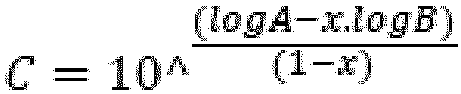
- B = MFR2 of Fraction (A)
- C = MFR2 of Fraction (B)
- A = final MFR2 (mixture) of multimodal HDPE
- X = weight fraction of Fraction (A)
- FRR was determined as the ratio between the MFR21 and the MFR2.
- Molecular weight averages (Mz, Mw and Mn), Molecular weight distribution (MWD) and its broadness, described by polydispersity index, PDI= Mw/Mn (wherein Mn is the number average molecular weight and Mw is the weight average molecular weight) were determined by Gel Permeation Chromatography (GPC) according to ISO 16014-1:2003, ISO 16014-2:2003, ISO 16014-4:2003 and ASTM D 6474-12 using the following formulas:


- For a constant elution volume interval ΔVi, where Ai, and Mi are the chromatographic peak slice area and polyolefin molecular weight (MW), respectively associated with the elution volume, Vi, where N is equal to the number of data points obtained from the chromatogram between the integration limits.
- A high temperature GPC instrument, equipped with either infrared (IR) detector (IR4 or IR5 from PolymerChar (Valencia, Spain), equipped with 3 x Agilent-PLgel Olexis and 1x Agilent-PLgel Olexis Guard columns was used. As the solvent and mobile phase 1,2,4-trichlorobenzene (TCB) stabilized with 250 mg/L 2,6-Di tert butyl-4-methyl-phenol) was used. The chromatographic system was operated at 160 °C and at a constant flow rate of 1 mL/min. 200 µL of sample solution was injected per analysis. Data collection was performed using either Agilent Cirrus software version 3.3 or PolymerChar GPC-IR control software.
- The column set was calibrated using universal calibration (according to ISO 16014-2:2003) with 19 narrow MWD polystyrene (PS) standards in the range of 0,5 kg/mol to 11 500 kg/mol. The PS standards were dissolved at room temperature over several hours. The conversion of the polystyrene peak molecular weight to polyolefin molecular weights is accomplished by using the Mark Houwink equation and the following Mark Houwink constants:


- A third order polynomial fit was used to fit the calibration data.
- All samples were prepared in the concentration range of 0,5 -1 mg/ml and dissolved at 160 °C for 2.5 hours for PP or 3 hours for PE under continuous gentle shaking.
- Quantitative nuclear-magnetic resonance (NMR) spectroscopy was used to quantify the comonomer content of the polymers.
- Quantitative 13C{1H} NMR spectra recorded in the molten-state using a Bruker Advance III 500 NMR spectrometer operating at 500.13 and 125.76 MHz for 1H and 13C respectively. All spectra were recorded using a 13C optimised 7 mm magic-angle spinning (MAS) probehead at 150°C using nitrogen gas for all pneumatics. Approximately 200 mg of material was packed into a 7 mm outer diameter zirconia MAS rotor and spun at 4 kHz. This setup was chosen primarily for the high sensitivity needed for rapid identification and accurate quantification. {klimke06, parkinson07, castignolles09} Standard single-pulse excitation was employed utilising the NOE at short recycle delays{pollard04, klimke06} and the RS-HEPT decoupling scheme{fillip05,griffin07}. A total of 1024 (1k) transients were acquired per spectra. Quantitative 13C{1H} NMR spectra were processed, integrated and relevant quantitative properties determined from the integrals. All chemical shifts are internally referenced to the bulk methylene signal (δ+) at 30.00 ppm.
- The amount of ethylene was quantified using the integral of the methylene (δ+) sites at 30.00 ppm accounting for the number of reporting sites per monomer:

- Characteristic signals corresponding to the incorporation of 1-butene were observed and the comonomer fraction calculated as the fraction of 1-butene in the polymer with respect to all monomer in the polymer:

- The amount isolated 1-butene incorporated in EEBEE sequences was quantified using the integral of the *B2 sites at 38.3 ppm accounting for the number of reporting sites per comonomer:

- The amount consecutively incorporated 1-butene in EEBBEE sequences was quantified using the integral of the ααB2B2 site at 39.4 ppm accounting for the number of reporting sites per comonomer:

- The amount non consecutively incorporated 1-butene in EEBEBEE sequences was quantified using the integral of the ββB2B2 site at 24.7 ppm accounting for the number of reporting sites per comonomer:

- Due to the overlap of the *B2 and *βB2B2 sites of isolated (EEBEE) and non-consecutivly incorporated (EEBEBEE) 1-butene respectively the total amount of isolated 1-butene incorporation is corrected based on the amount of non-consecutive 1-butene present:

- The total 1-butene content was calculated based on the sum of isolated, consecutive and non consecutively incorporated 1-butene:

- The total mole fraction of 1-butene in the polymer was then calculated as:

- Characteristic signals corresponding to the incorporation of 1-hexene were observed and the comonomer fraction calculated as the fraction of 1-hexene in the polymer with respect to all monomer in the polymer:

- The amount isolated 1-hexene incorporated in EEHEE sequences was quantified using the integral of the *B4 sites at 39.9 ppm accounting for the number of reporting sites per comonomer:

- The amount consecutively incorporated 1-hexene in EEHHEE sequences was quantified using the integral of the ααB4B4 site at 40.5 ppm accounting for the number of reporting sites per comonomer:

- The amount non consecutively incorporated 1-hexene in EEHEHEE sequences was quantified using the integral of the ββB4B4 site at 24.7 ppm accounting for the number of reporting sites per comonomer:

- The total mole fraction of 1-hexene in the polymer was then calculated as:

- The mole percent comonomer incorporation is calculated from the mole fraction:


- The weight percent comonomer incorporation is calculated from the mole fraction:
B [wt%] = 100 * ( fB * 56.11) / ( (fB * 56.11) + (fH * 84.16) + ((1-(fB + fH)) * 28.05) ) H [wit%] = 100 * ( fH * 84.16 ) / ( (fB * 56.11) + (fH * 84.16) + ((1-(fB + fH)) * 28.05) ) - References:
- Klimke, K., Parkinson, M., Piel, C., Kaminsky, W., Spiess, H.W., Wilhelm, M., Macromol. Chem. Phys. 2006;207:382.
- Parkinson, M., Klimke, K., Spiess, H.W., Wilhelm, M., Macromol. Chem. Phys. 2007;208:2128.
- Pollard, M., Klimke, K., Graf, R., Spiess, H.W., Wilhelm, M., Sperber, O., Piel, C., Kaminsky, W., Macromolecules 2004;37:813.
- Filip, X., Tripon, C., Filip, C., J. Mag. Resn. 2005, 176, 239
- Griffin, J.M., Tripon, C., Samoson, A., Filip, C., and Brown, S.P., Mag. Res. in Chem. 2007 45, S1, S198
- Castignolles, P., Graf, R., Parkinson, M., Wilhelm, M., Gaborieau, M., Polymer 50 (2009) 2373
- Busico, V., Cipullo, R., Prog. Polym. Sci. 26 (2001) 443
- Busico, V., Cipullo, R., Monaco, G., Vacatello, M., Segre, A.L., Macromoleucles 30 (1997) 6251
- Zhou, Z., Kuemmerle, R., Qiu, X., Redwine, D., Cong, R., Taha, A., Baugh, D. Winniford, B., J. Mag. Reson. 187 (2007) 225
- Busico, V., Carbonniere, P., Cipullo, R., Pellecchia, R., Severn, J., Talarico, G., Macromol. Rapid Commun. 2007, 28, 1128
- Resconi, L., Cavallo, L., Fait, A., Piemontesi, F., Chem. Rev. 2000, 100, 1253
- The density was measured according to ISO 1183 and ISO1872-2 for sample preparation.
- Tensile properties were measured on injection moulded samples according to ISO 527-2, Specimen type Multipurpose bar 1A , 4 mm thick. Tensile modulus was measured at a speed of 1 mm/min. Sample preparation was done according to ISO 17855-2.
- Notched Impact strength was measured according to ISO179, 1eA at +23 °C, specimen 80 * 10 * 4 mm3. Sample preparation was done according to ISO 17855-2.
- The CoF was measured on 150 x 80 x 1mm3 thick injection moulded specimen based on ISO 8295. The injection moulding was done according to ISO 17855-2. The CoF test was performed on a Zwick Z1.0 S machine. The following conditions were used:
- Test speed: 100 mm/min ± 10 mm/min
- Measuring distance: 56 mm
- Loading weight: 200 g ± 2 g
- Before the measurements the specimen was stored at 23°C, RH 50% for desired time, e.g. 1 day, 3 days, 7 days, etc.
- Materials:
- Slip Agent 1: Finawax S, a stearamide commercially available from Fine Organics.
- Slip Agent 2: Finawax B, a Behenamide commercially available from Fine Organics.
- Slip Agent 3: Finawax E, a Erucamide commercially available from Fine Organics.
- HDPE1: a bimodal HDPE produced with a ZN catalyst (as disclosed in
EP 2994506 ) in a pilot plant, with a configuration of prepolymerisation- loop - gas phase reactor, having MFR 0.8 g/10min, density 955.5 kg/m3. - HDPE2: a bimodal HDPE produced with a ZN catalyst (as disclosed in
EP 2994506 ) in a pilot plant, with a configuration of prepolymerisation- loop - gas phase reactor, having MFR 1.28 g/10min, density 962.5 kg/m3. - HDPE3: a unimodal HDPE produced with a Lynx 200 catalyst (supplied by Grace Catalysts Technologies) in a pilot plant, with a configuration of prepolymerisation-loop reactor, having MFR 0.97 g/10min, density 961.5 kg/m3.
- HDPE4: is described in
EP 2402391 , and also in Table 1. - Table 1 shows the typical polymerisation parameters and final polymer properties for the HDPE1, HDPE2, HDPE3 and HDPE4.
Table 1 HDPE1 HDPE2 HDPE3 HDPE 4 Prepoly Temp. (°C) 70 70 60 70 Press. (kPa) 5700 5685 5474 6300 H2 (g/h) 5.0 5.0 5.0 5.2 Loop reactor Temp. (°C) 95 95 95 95 Press. (kPa) 5500 5365 5188 5800 C2 conc. (mol-%) 3.5 3.9 4.2 6.8 H2/C2 (mol/kmol) 430.0 335.0 91.2 347 Density 970 970 960 970 split % 49.0 45.7 100.0 52 MFR2 (g/10 min) 350 320 0.97 400 GPR Temp. (°C) 85 85 - 85 Press. (kPa) 2000 2000 - 2000 H2/C2 (mol/kmol) 110 132 - 81 C4/C2 (mol/kmol) 25.0 8.3 - 80 split % 51.0 54.3 - 48 Pellet Density (kg/m3) 955.5 962.5 961.5 954.0 MFR2 (g/10 min) 0.8 1.3 0.94 1.5 MFR21 (g/10 min) 47.35 77.4 34 100 MFR21/MFR2 59.2 60.9 36 67 TM (MPa) 950 1028 1031 920 NIS (kJ/m2) 17.8 16.1 37.7 12 MFR in GPR 0.002 0.012 - 0.004 Density in GPR 941.6 956.5 - 937 Δdensity* 28.4 13.5 33 * Δdensity = Density (low molecular weight) - Density (high molecular weight) - The desired amount of HDPE powder and additive were premixed in an intensive mixer and then compounded on a ZSK 57 twin screw extruder. The melt temperature was 210°C, production rate was 200kg/h. The following additives were added: 0.05wt% Irganox 1010 (BASF), 0.2 wt% Irgafos 168 (BASF) & 0.05 wt% CEASIT FI, where wt% are relative to total weight of composition (the sum HDPE powder + additive = 100%).
- Five compositions were prepared as shown in Table 2 via blending. The blending was done on a ZSK 18 twin screw extruder, with melt temperature of 210°C, output rate 7kg/h. The coefficient of friction was measured on 150 x 80 x 1 mm3 injection moulded specimens at a series of time periods and results are shown in Table 2.
- As can be seen, the combination of saturated amide and bimodal HDPE gives sufficient slip effect, which is at least comparable to that obtained with Erucamide in CE1 (which presents the known problems of oxidation). CE2 is a combination of unimodal HDPE and saturated amide, it has very poor slip effect compared to the inventive bimodal HDPE compositions with the same recipe. Generally, the IEs have CoF < 0.3 which fulfills all needs. Combining the mechanical properties and the CoF effect, the results show that the IEs gives the best combination of slip effect and improved mechanical properties.
Table 2: Compositions and Properties of Moulded Articles. IE1 IE2 IE3 CE1 CE2 HDPE1 (wt%) 99.8 99.8 99.8 HDPE2 (wt%) 99.8 HDPE3 (wt%) 99.8 Slip Agent 1 (wt%) 0.2 0.2 0.2 Slip Agent 2 (wt%) 0.2 Slip Agent 3 (wt%) 0.2 MFR2 of blend (g/10 min) 0.8 0.85 1.28 0.8 1.0 Coefficient of Friction 1 day 0.2 0.29 0.23 0.12 0.51 3 days 0.19 0.24 0.24 0.09 0.49 7 days 0.21 0.23 0.22 0.17 0.32 14 days 0.15 0.20 0.21 0.09 0.33
Claims (15)
- A polymer composition comprising:(i) 95.0 to 99.95 wt%, relative to the total weight of the polymer composition, of a multimodal high density polyethylene (HDPE) with a density of 945 to 980 kg/m3 measured according to ISO 1183, and an MFR2 of 0.1 to 1.3 g/10min measured according to ISO 1133 at 190 °C and a load of 2.16 kg; and wherein the multimodal HDPE comprises at least two fractions:(A) 30 to 70 wt%, relative to the total weight of the multimodal HDPE, of a lower molecular weight fraction being a polyethylene with a density in the range of 955 to 980 kg/m3 measured according to ISO 1183 and an MFR2 of 100 to 600 g/10 min measured according to ISO 1133 at 190 °C and a load of 2.16 kg; and(B) 30 to 70 wt%, relative to the total weight of the multimodal HDPE, of a higher molecular weight fraction being a polyethylene with a density in the range of 930 to 960 kg/m3 measured according to ISO 1183 and an MFR2 of 0.0001 to 1.0 g/10 min measured according to ISO 1133 at 190 °C and a load of 2.16 kg; and(ii) 0.08 to 0.4 wt%, relative to the total weight of the polymer composition, of at least one saturated amide slip agent.
- The polymer composition as claimed in claim 1, wherein the lower molecular weight fraction (A) of the HDPE has an MFR2 of 125 to 500 g/10min, preferably 150 to 400 g/10min, more preferably 200 to 380 g/10 min.
- The polymer composition as claimed in claim 1 or 2, wherein the HDPE has a density of 950 to 970 kg/m3, preferably 951 to 965 kg/m3, more preferably 952 to 963 kg/m3, even more preferably 953 to 960 kg/m3.
- The polymer composition as claimed in any of claims 1 to 3, wherein the HDPE has an MFR21 of 15 to 90 g/10min, such as 20 to 85 g/10 min, most preferably 30 to 80 g/10 min measured according to ISO 1133 at 190 °C and a load of 21.6 kg.
- The polymer composition as claimed in any of claim 1 to 4, wherein the HDPE has a tensile modulus measured according to ISO 527-2, in the range 930 to 1500 MPa, preferably 940 to 1200 MPa
- The polymer composition as claimed in any of claims 1 to 5, wherein the HDPE has a notched impact strength measured according to ISO 179, 1eA at +23 °C, in the range 13 to 25 kJ/m2, preferably 15 to 20 kJ/m2.
- The polymer composition as claimed in any of claims 1 to 6, wherein said lower molecular weight (LMW) fraction (A) is an ethylene homopolymer.
- The polymer composition as claimed in any of claims 1 to 7, wherein said higher molecular weight (HMW) fraction (B) is a copolymer of ethylene with at least one alpha-olefin comonomer, preferably but-1-ene.
- The polymer composition as claimed in any of claims 1 to 8, wherein said HDPE comprises 35 to 60 wt% of fraction (A) and 40 to 65 wt% fraction (B), preferably 40 to 55 wt% of fraction (A) and 45 to 60 wt% fraction (B), relative to the total weight of the HDPE as a whole.
- The polymer composition as claimed in any of claims 1 to 9, wherein the saturated amide slip agent is selected from the group consisting of behenamide, arachidamide, stearamide, palmitamide, myristamide, lauramide and mixtures thereof, preferably behenamide, stearamide and mixtures thereof.
- The polymer composition as claimed in any of claims 1 to 10, wherein said composition comprises 96.0 to 99.92 wt% of the HDPE, relative to the total weight of the composition as a whole, preferably 97.0 to 99.90 wt%.
- The polymer composition as claimed in any of claims 1 to 11, wherein said composition comprises 0.1 to 0.3 wt% of the amide slip agent, relative to the total weight of the composition as a whole, preferably 0.12 to 0.25 wt%.
- An article comprising a polymer composition as claimed in any of claims 1 to 12.
- The article as claimed in claim 13, wherein said article is an injection or compression moulded article, preferably an injection moulded article, such as a cap or closure.
- Use of the polymer composition as claimed in any one of claims 1 to 12 in the manufacture of an article, preferably an injection or compression moulded article, such as a cap or closure.
Priority Applications (3)
| Application Number | Priority Date | Filing Date | Title |
|---|---|---|---|
| EP22185003.5A EP4306442B1 (en) | 2022-07-14 | 2022-07-14 | Composition |
| CN202380053656.7A CN119546525A (en) | 2022-07-14 | 2023-07-13 | Composition |
| PCT/EP2023/069536 WO2024013327A1 (en) | 2022-07-14 | 2023-07-13 | Composition |
Applications Claiming Priority (1)
| Application Number | Priority Date | Filing Date | Title |
|---|---|---|---|
| EP22185003.5A EP4306442B1 (en) | 2022-07-14 | 2022-07-14 | Composition |
Publications (2)
| Publication Number | Publication Date |
|---|---|
| EP4306442A1 EP4306442A1 (en) | 2024-01-17 |
| EP4306442B1 true EP4306442B1 (en) | 2025-05-07 |
Family
ID=82608711
Family Applications (1)
| Application Number | Title | Priority Date | Filing Date |
|---|---|---|---|
| EP22185003.5A Active EP4306442B1 (en) | 2022-07-14 | 2022-07-14 | Composition |
Country Status (3)
| Country | Link |
|---|---|
| EP (1) | EP4306442B1 (en) |
| CN (1) | CN119546525A (en) |
| WO (1) | WO2024013327A1 (en) |
Family Cites Families (30)
| Publication number | Priority date | Publication date | Assignee | Title |
|---|---|---|---|---|
| US3242150A (en) | 1960-03-31 | 1966-03-22 | Phillips Petroleum Co | Method and apparatus for the recovery of solid olefin polymer from a continuous path reaction zone |
| US3405109A (en) | 1960-10-03 | 1968-10-08 | Phillips Petroleum Co | Polymerization process |
| US3324093A (en) | 1963-10-21 | 1967-06-06 | Phillips Petroleum Co | Loop reactor |
| US3374211A (en) | 1964-07-27 | 1968-03-19 | Phillips Petroleum Co | Solids recovery from a flowing stream |
| US4582816A (en) | 1985-02-21 | 1986-04-15 | Phillips Petroleum Company | Catalysts, method of preparation and polymerization processes therewith |
| US5565175A (en) | 1990-10-01 | 1996-10-15 | Phillips Petroleum Company | Apparatus and method for producing ethylene polymer |
| FI89929C (en) | 1990-12-28 | 1993-12-10 | Neste Oy | Process for homo- or copolymerization of ethylene |
| FI942949A0 (en) | 1994-06-20 | 1994-06-20 | Borealis Polymers Oy | Prokatalysator Foer production av etenpolymerer och foerfarande Foer framstaellning daerav |
| FI96216C (en) | 1994-12-16 | 1996-05-27 | Borealis Polymers Oy | Process for the production of polyethylene |
| FI101479B1 (en) | 1994-12-22 | 1998-06-30 | Borealis Polymers Oy | Process for avoiding soiling in polymerization reactors |
| FI104827B (en) | 1995-04-12 | 2000-04-14 | Borealis Polymers Oy | Process for Elimination of Pollution and Layer in Gas Phase Reactors |
| SK284880B6 (en) | 1996-05-17 | 2006-01-05 | Bp Chemicals Limited | Polyolefin copolymer composition, film or other article of manufacture and blend comprising thereof |
| US5767034A (en) | 1996-05-31 | 1998-06-16 | Intevep, S.A. | Olefin polymerization catalyst with additive comprising aluminum-silicon composition, calixarene derivatives or cyclodextrin derivatives |
| US6239235B1 (en) | 1997-07-15 | 2001-05-29 | Phillips Petroleum Company | High solids slurry polymerization |
| FI111372B (en) | 1998-04-06 | 2003-07-15 | Borealis Polymers Oy | Catalyst component for polymerization of olefins, its preparation and use thereof |
| GB0001914D0 (en) | 2000-01-27 | 2000-03-22 | Borealis Polymers Oy | Catalyst |
| EP1136524A1 (en) | 2000-03-22 | 2001-09-26 | SOLVAY POLYOLEFINS EUROPE - BELGIUM (Société Anonyme) | Polyethylene composition and production process for objects formed therefrom |
| EP1310295B1 (en) | 2001-10-30 | 2007-07-18 | Borealis Technology Oy | Polymerisation reactor |
| EP1378528B1 (en) | 2002-06-24 | 2005-04-13 | Borealis Technology Oy | A process for the production of a linear low-density polyethylene composition |
| DE60223926T2 (en) | 2002-10-30 | 2008-11-13 | Borealis Technology Oy | Process and apparatus for the production of olefin polymers |
| EP1591460B1 (en) | 2004-04-29 | 2006-06-14 | Borealis Technology Oy | Process for producing polyethylene |
| FI20040755A0 (en) | 2004-06-02 | 2004-06-02 | Borealis Tech Oy | A process for the preparation of an olefin polymerization catalyst and a catalyst prepared by this process |
| CN1923861B (en) | 2005-09-02 | 2012-01-18 | 北方技术股份有限公司 | Olefin polymerization method with olefin polymerization catalyst |
| EP2402391B1 (en) | 2010-06-29 | 2013-07-31 | Borealis AG | Bimodal polyethylene composition for injection moulded articles |
| EP2746306B1 (en) | 2012-12-21 | 2017-10-04 | Borealis AG | Supported Ziegler Natta procatalyst for ethylene polymerisation |
| EP2994506B2 (en) | 2013-05-09 | 2020-07-01 | Borealis AG | Hdpe |
| BR112017012698B1 (en) | 2014-12-18 | 2021-10-26 | Borealis Ag | ZIEGLER-NATTA CATALYST, SOLID MAGNESIUM CHLORIDE CATALYST COMPONENT, ITS USE, PRODUCTION METHOD AND PROCESS FOR THE PRODUCTION OF ETHYLENE POLYMER |
| WO2016178245A1 (en) | 2015-05-07 | 2016-11-10 | Fine Research & Development Centre Pvt Ltd | A polypropylene cap or film composition |
| WO2017093390A1 (en) * | 2015-12-02 | 2017-06-08 | Abu Dhabi Polymers Company Limited (Borouge) L.L.C. | Hdpe |
| EP4234614A1 (en) | 2022-02-25 | 2023-08-30 | Borealis AG | A film comprising a polyethylene composition having improved gloss |
-
2022
- 2022-07-14 EP EP22185003.5A patent/EP4306442B1/en active Active
-
2023
- 2023-07-13 CN CN202380053656.7A patent/CN119546525A/en active Pending
- 2023-07-13 WO PCT/EP2023/069536 patent/WO2024013327A1/en not_active Ceased
Also Published As
| Publication number | Publication date |
|---|---|
| WO2024013327A1 (en) | 2024-01-18 |
| EP4306442A1 (en) | 2024-01-17 |
| CN119546525A (en) | 2025-02-28 |
Similar Documents
| Publication | Publication Date | Title |
|---|---|---|
| US12012504B2 (en) | Process for the preparation of multimodal high density polyethylene | |
| EP2994506B2 (en) | Hdpe | |
| EP4151678A1 (en) | Biaxially oriented film | |
| EP4239015B1 (en) | Monoaxially oriented film comprising a polyethylene composition | |
| EP2894174B1 (en) | Polyethylene composition with high flexibility and high temperature resistance suitable for pipe applications | |
| WO2024068977A1 (en) | Multimodal ethylene copolymer composition and films comprising the same | |
| EP4239014A1 (en) | Film comprising a polyethylene composition | |
| EP3880749B1 (en) | Composition | |
| EP4306442B1 (en) | Composition | |
| EP4306444B1 (en) | Composition | |
| EP4163309A1 (en) | Hdpe | |
| EP4393967A1 (en) | Pe100-rc with butene as comonomer | |
| EP4234614A1 (en) | A film comprising a polyethylene composition having improved gloss | |
| EP4234626B1 (en) | A polyethylene composition with improved stiffness and toughness | |
| EP4234627B1 (en) | A polyethylene composition with improved stiffness and toughness | |
| EP4386046A1 (en) | Composition | |
| EP4431552B1 (en) | Biaxially oriented polyethylene film with improved stiffness | |
| EP4455171A1 (en) | Moulded articles | |
| EP4389786A1 (en) | Heterophasic polypropylene composition | |
| EP4389819A1 (en) | Polyolefin composition with excellent balance of properties |
Legal Events
| Date | Code | Title | Description |
|---|---|---|---|
| PUAI | Public reference made under article 153(3) epc to a published international application that has entered the european phase |
Free format text: ORIGINAL CODE: 0009012 |
|
| STAA | Information on the status of an ep patent application or granted ep patent |
Free format text: STATUS: THE APPLICATION HAS BEEN PUBLISHED |
|
| AK | Designated contracting states |
Kind code of ref document: A1 Designated state(s): AL AT BE BG CH CY CZ DE DK EE ES FI FR GB GR HR HU IE IS IT LI LT LU LV MC MK MT NL NO PL PT RO RS SE SI SK SM TR |
|
| TPAC | Observations filed by third parties |
Free format text: ORIGINAL CODE: EPIDOSNTIPA |
|
| STAA | Information on the status of an ep patent application or granted ep patent |
Free format text: STATUS: REQUEST FOR EXAMINATION WAS MADE |
|
| 17P | Request for examination filed |
Effective date: 20240708 |
|
| RBV | Designated contracting states (corrected) |
Designated state(s): AL AT BE BG CH CY CZ DE DK EE ES FI FR GB GR HR HU IE IS IT LI LT LU LV MC MK MT NL NO PL PT RO RS SE SI SK SM TR |
|
| STAA | Information on the status of an ep patent application or granted ep patent |
Free format text: STATUS: EXAMINATION IS IN PROGRESS |
|
| 17Q | First examination report despatched |
Effective date: 20240918 |
|
| GRAP | Despatch of communication of intention to grant a patent |
Free format text: ORIGINAL CODE: EPIDOSNIGR1 |
|
| STAA | Information on the status of an ep patent application or granted ep patent |
Free format text: STATUS: GRANT OF PATENT IS INTENDED |
|
| INTG | Intention to grant announced |
Effective date: 20250218 |
|
| GRAS | Grant fee paid |
Free format text: ORIGINAL CODE: EPIDOSNIGR3 |
|
| GRAA | (expected) grant |
Free format text: ORIGINAL CODE: 0009210 |
|
| STAA | Information on the status of an ep patent application or granted ep patent |
Free format text: STATUS: THE PATENT HAS BEEN GRANTED |
|
| AK | Designated contracting states |
Kind code of ref document: B1 Designated state(s): AL AT BE BG CH CY CZ DE DK EE ES FI FR GB GR HR HU IE IS IT LI LT LU LV MC MK MT NL NO PL PT RO RS SE SI SK SM TR |
|
| P01 | Opt-out of the competence of the unified patent court (upc) registered |
Free format text: CASE NUMBER: APP_14943/2025 Effective date: 20250327 |
|
| REG | Reference to a national code |
Ref country code: GB Ref legal event code: FG4D |
|
| REG | Reference to a national code |
Ref country code: CH Ref legal event code: EP |
|
| REG | Reference to a national code |
Ref country code: DE Ref legal event code: R096 Ref document number: 602022014143 Country of ref document: DE |
|
| REG | Reference to a national code |
Ref country code: IE Ref legal event code: FG4D |
|
| REG | Reference to a national code |
Ref country code: NL Ref legal event code: FP |
|
| RAP4 | Party data changed (patent owner data changed or rights of a patent transferred) |
Owner name: BOREALIS GMBH |
|
| PGFP | Annual fee paid to national office [announced via postgrant information from national office to epo] |
Ref country code: NL Payment date: 20250721 Year of fee payment: 4 |
|
| PG25 | Lapsed in a contracting state [announced via postgrant information from national office to epo] |
Ref country code: FI Free format text: LAPSE BECAUSE OF FAILURE TO SUBMIT A TRANSLATION OF THE DESCRIPTION OR TO PAY THE FEE WITHIN THE PRESCRIBED TIME-LIMIT Effective date: 20250507 Ref country code: ES Free format text: LAPSE BECAUSE OF FAILURE TO SUBMIT A TRANSLATION OF THE DESCRIPTION OR TO PAY THE FEE WITHIN THE PRESCRIBED TIME-LIMIT Effective date: 20250507 Ref country code: PT Free format text: LAPSE BECAUSE OF FAILURE TO SUBMIT A TRANSLATION OF THE DESCRIPTION OR TO PAY THE FEE WITHIN THE PRESCRIBED TIME-LIMIT Effective date: 20250908 |
|
| PGFP | Annual fee paid to national office [announced via postgrant information from national office to epo] |
Ref country code: DE Payment date: 20250722 Year of fee payment: 4 |
|
| REG | Reference to a national code |
Ref country code: LT Ref legal event code: MG9D |
|
| PG25 | Lapsed in a contracting state [announced via postgrant information from national office to epo] |
Ref country code: NO Free format text: LAPSE BECAUSE OF FAILURE TO SUBMIT A TRANSLATION OF THE DESCRIPTION OR TO PAY THE FEE WITHIN THE PRESCRIBED TIME-LIMIT Effective date: 20250807 Ref country code: GR Free format text: LAPSE BECAUSE OF FAILURE TO SUBMIT A TRANSLATION OF THE DESCRIPTION OR TO PAY THE FEE WITHIN THE PRESCRIBED TIME-LIMIT Effective date: 20250808 |
|
| PG25 | Lapsed in a contracting state [announced via postgrant information from national office to epo] |
Ref country code: PL Free format text: LAPSE BECAUSE OF FAILURE TO SUBMIT A TRANSLATION OF THE DESCRIPTION OR TO PAY THE FEE WITHIN THE PRESCRIBED TIME-LIMIT Effective date: 20250507 |
|
| PGFP | Annual fee paid to national office [announced via postgrant information from national office to epo] |
Ref country code: IT Payment date: 20250731 Year of fee payment: 4 |
|
| REG | Reference to a national code |
Ref country code: AT Ref legal event code: MK05 Ref document number: 1792273 Country of ref document: AT Kind code of ref document: T Effective date: 20250507 |
|
| PG25 | Lapsed in a contracting state [announced via postgrant information from national office to epo] |
Ref country code: BG Free format text: LAPSE BECAUSE OF FAILURE TO SUBMIT A TRANSLATION OF THE DESCRIPTION OR TO PAY THE FEE WITHIN THE PRESCRIBED TIME-LIMIT Effective date: 20250507 |
|
| PG25 | Lapsed in a contracting state [announced via postgrant information from national office to epo] |
Ref country code: HR Free format text: LAPSE BECAUSE OF FAILURE TO SUBMIT A TRANSLATION OF THE DESCRIPTION OR TO PAY THE FEE WITHIN THE PRESCRIBED TIME-LIMIT Effective date: 20250507 |
|
| PG25 | Lapsed in a contracting state [announced via postgrant information from national office to epo] |
Ref country code: AT Free format text: LAPSE BECAUSE OF FAILURE TO SUBMIT A TRANSLATION OF THE DESCRIPTION OR TO PAY THE FEE WITHIN THE PRESCRIBED TIME-LIMIT Effective date: 20250507 |
|
| PGFP | Annual fee paid to national office [announced via postgrant information from national office to epo] |
Ref country code: FR Payment date: 20250725 Year of fee payment: 4 |
|
| PG25 | Lapsed in a contracting state [announced via postgrant information from national office to epo] |
Ref country code: RS Free format text: LAPSE BECAUSE OF FAILURE TO SUBMIT A TRANSLATION OF THE DESCRIPTION OR TO PAY THE FEE WITHIN THE PRESCRIBED TIME-LIMIT Effective date: 20250807 |
|
| PG25 | Lapsed in a contracting state [announced via postgrant information from national office to epo] |
Ref country code: IS Free format text: LAPSE BECAUSE OF FAILURE TO SUBMIT A TRANSLATION OF THE DESCRIPTION OR TO PAY THE FEE WITHIN THE PRESCRIBED TIME-LIMIT Effective date: 20250907 |
|
| PG25 | Lapsed in a contracting state [announced via postgrant information from national office to epo] |
Ref country code: LV Free format text: LAPSE BECAUSE OF FAILURE TO SUBMIT A TRANSLATION OF THE DESCRIPTION OR TO PAY THE FEE WITHIN THE PRESCRIBED TIME-LIMIT Effective date: 20250507 |
|
| PG25 | Lapsed in a contracting state [announced via postgrant information from national office to epo] |
Ref country code: DK Free format text: LAPSE BECAUSE OF FAILURE TO SUBMIT A TRANSLATION OF THE DESCRIPTION OR TO PAY THE FEE WITHIN THE PRESCRIBED TIME-LIMIT Effective date: 20250507 Ref country code: SM Free format text: LAPSE BECAUSE OF FAILURE TO SUBMIT A TRANSLATION OF THE DESCRIPTION OR TO PAY THE FEE WITHIN THE PRESCRIBED TIME-LIMIT Effective date: 20250507 |
|
| PG25 | Lapsed in a contracting state [announced via postgrant information from national office to epo] |
Ref country code: CZ Free format text: LAPSE BECAUSE OF FAILURE TO SUBMIT A TRANSLATION OF THE DESCRIPTION OR TO PAY THE FEE WITHIN THE PRESCRIBED TIME-LIMIT Effective date: 20250507 |
|
| PG25 | Lapsed in a contracting state [announced via postgrant information from national office to epo] |
Ref country code: EE Free format text: LAPSE BECAUSE OF FAILURE TO SUBMIT A TRANSLATION OF THE DESCRIPTION OR TO PAY THE FEE WITHIN THE PRESCRIBED TIME-LIMIT Effective date: 20250507 |
|
| PG25 | Lapsed in a contracting state [announced via postgrant information from national office to epo] |
Ref country code: SK Free format text: LAPSE BECAUSE OF FAILURE TO SUBMIT A TRANSLATION OF THE DESCRIPTION OR TO PAY THE FEE WITHIN THE PRESCRIBED TIME-LIMIT Effective date: 20250507 |
|
| PLBI | Opposition filed |
Free format text: ORIGINAL CODE: 0009260 |