EP4306432A1 - Device for latching a door of an oxygen mask container in an aircraft cabin - Google Patents
Device for latching a door of an oxygen mask container in an aircraft cabin Download PDFInfo
- Publication number
- EP4306432A1 EP4306432A1 EP22185218.9A EP22185218A EP4306432A1 EP 4306432 A1 EP4306432 A1 EP 4306432A1 EP 22185218 A EP22185218 A EP 22185218A EP 4306432 A1 EP4306432 A1 EP 4306432A1
- Authority
- EP
- European Patent Office
- Prior art keywords
- door
- latching
- hook element
- oxygen mask
- test control
- Prior art date
- Legal status (The legal status is an assumption and is not a legal conclusion. Google has not performed a legal analysis and makes no representation as to the accuracy of the status listed.)
- Granted
Links
Images

Classifications
-
- E—FIXED CONSTRUCTIONS
- E05—LOCKS; KEYS; WINDOW OR DOOR FITTINGS; SAFES
- E05B—LOCKS; ACCESSORIES THEREFOR; HANDCUFFS
- E05B47/00—Operating or controlling locks or other fastening devices by electric or magnetic means
- E05B47/0001—Operating or controlling locks or other fastening devices by electric or magnetic means with electric actuators; Constructional features thereof
- E05B47/0012—Operating or controlling locks or other fastening devices by electric or magnetic means with electric actuators; Constructional features thereof with rotary electromotors
-
- E—FIXED CONSTRUCTIONS
- E05—LOCKS; KEYS; WINDOW OR DOOR FITTINGS; SAFES
- E05B—LOCKS; ACCESSORIES THEREFOR; HANDCUFFS
- E05B47/00—Operating or controlling locks or other fastening devices by electric or magnetic means
- E05B47/02—Movement of the bolt by electromagnetic means; Adaptation of locks, latches, or parts thereof, for movement of the bolt by electromagnetic means
- E05B47/026—Movement of the bolt by electromagnetic means; Adaptation of locks, latches, or parts thereof, for movement of the bolt by electromagnetic means the bolt moving rectilinearly
-
- A—HUMAN NECESSITIES
- A62—LIFE-SAVING; FIRE-FIGHTING
- A62B—DEVICES, APPARATUS OR METHODS FOR LIFE-SAVING
- A62B25/00—Devices for storing or holding or carrying respiratory or breathing apparatus
- A62B25/005—Devices for storing or holding or carrying respiratory or breathing apparatus for high altitude
-
- A—HUMAN NECESSITIES
- A62—LIFE-SAVING; FIRE-FIGHTING
- A62B—DEVICES, APPARATUS OR METHODS FOR LIFE-SAVING
- A62B7/00—Respiratory apparatus
- A62B7/14—Respiratory apparatus for high-altitude aircraft
-
- B—PERFORMING OPERATIONS; TRANSPORTING
- B64—AIRCRAFT; AVIATION; COSMONAUTICS
- B64D—EQUIPMENT FOR FITTING IN OR TO AIRCRAFT; FLIGHT SUITS; PARACHUTES; ARRANGEMENT OR MOUNTING OF POWER PLANTS OR PROPULSION TRANSMISSIONS IN AIRCRAFT
- B64D11/00—Passenger or crew accommodation; Flight-deck installations not otherwise provided for
-
- B—PERFORMING OPERATIONS; TRANSPORTING
- B64—AIRCRAFT; AVIATION; COSMONAUTICS
- B64D—EQUIPMENT FOR FITTING IN OR TO AIRCRAFT; FLIGHT SUITS; PARACHUTES; ARRANGEMENT OR MOUNTING OF POWER PLANTS OR PROPULSION TRANSMISSIONS IN AIRCRAFT
- B64D11/00—Passenger or crew accommodation; Flight-deck installations not otherwise provided for
- B64D11/06—Arrangements of seats, or adaptations or details specially adapted for aircraft seats
- B64D11/0627—Seats combined with storage means
- B64D11/0629—Seats combined with storage means the storage means being specially adapted for emergency equipment
- B64D11/0632—Seats combined with storage means the storage means being specially adapted for emergency equipment for breathing apparatus
-
- B—PERFORMING OPERATIONS; TRANSPORTING
- B64—AIRCRAFT; AVIATION; COSMONAUTICS
- B64F—GROUND OR AIRCRAFT-CARRIER-DECK INSTALLATIONS SPECIALLY ADAPTED FOR USE IN CONNECTION WITH AIRCRAFT; DESIGNING, MANUFACTURING, ASSEMBLING, CLEANING, MAINTAINING OR REPAIRING AIRCRAFT, NOT OTHERWISE PROVIDED FOR; HANDLING, TRANSPORTING, TESTING OR INSPECTING AIRCRAFT COMPONENTS, NOT OTHERWISE PROVIDED FOR
- B64F5/00—Designing, manufacturing, assembling, cleaning, maintaining or repairing aircraft, not otherwise provided for; Handling, transporting, testing or inspecting aircraft components, not otherwise provided for
- B64F5/60—Testing or inspecting aircraft components or systems
-
- E—FIXED CONSTRUCTIONS
- E05—LOCKS; KEYS; WINDOW OR DOOR FITTINGS; SAFES
- E05B—LOCKS; ACCESSORIES THEREFOR; HANDCUFFS
- E05B17/00—Accessories in connection with locks
- E05B17/20—Means independent of the locking mechanism for preventing unauthorised opening, e.g. for securing the bolt in the fastening position
-
- E—FIXED CONSTRUCTIONS
- E05—LOCKS; KEYS; WINDOW OR DOOR FITTINGS; SAFES
- E05B—LOCKS; ACCESSORIES THEREFOR; HANDCUFFS
- E05B17/00—Accessories in connection with locks
- E05B17/22—Means for operating or controlling lock or fastening device accessories, i.e. other than the fastening members, e.g. switches, indicators
-
- E—FIXED CONSTRUCTIONS
- E05—LOCKS; KEYS; WINDOW OR DOOR FITTINGS; SAFES
- E05B—LOCKS; ACCESSORIES THEREFOR; HANDCUFFS
- E05B41/00—Locks with visible indication as to whether the lock is locked or unlocked
-
- E—FIXED CONSTRUCTIONS
- E05—LOCKS; KEYS; WINDOW OR DOOR FITTINGS; SAFES
- E05B—LOCKS; ACCESSORIES THEREFOR; HANDCUFFS
- E05B47/00—Operating or controlling locks or other fastening devices by electric or magnetic means
- E05B47/0001—Operating or controlling locks or other fastening devices by electric or magnetic means with electric actuators; Constructional features thereof
- E05B47/0002—Operating or controlling locks or other fastening devices by electric or magnetic means with electric actuators; Constructional features thereof with electromagnets
-
- B—PERFORMING OPERATIONS; TRANSPORTING
- B64—AIRCRAFT; AVIATION; COSMONAUTICS
- B64D—EQUIPMENT FOR FITTING IN OR TO AIRCRAFT; FLIGHT SUITS; PARACHUTES; ARRANGEMENT OR MOUNTING OF POWER PLANTS OR PROPULSION TRANSMISSIONS IN AIRCRAFT
- B64D2231/00—Emergency oxygen systems
- B64D2231/02—Supply or distribution systems
- B64D2231/025—Oxygen masks; Mask storages; Features related to mask deployment
-
- E—FIXED CONSTRUCTIONS
- E05—LOCKS; KEYS; WINDOW OR DOOR FITTINGS; SAFES
- E05B—LOCKS; ACCESSORIES THEREFOR; HANDCUFFS
- E05B47/00—Operating or controlling locks or other fastening devices by electric or magnetic means
- E05B2047/0048—Circuits, feeding, monitoring
- E05B2047/0067—Monitoring
-
- E—FIXED CONSTRUCTIONS
- E05—LOCKS; KEYS; WINDOW OR DOOR FITTINGS; SAFES
- E05B—LOCKS; ACCESSORIES THEREFOR; HANDCUFFS
- E05B65/00—Locks or fastenings for special use
- E05B65/06—Locks or fastenings for special use for swing doors or windows, i.e. opening inwards and outwards
Definitions
- the invention relates to a device for latching a door of an oxygen mask container in an aircraft cabin.
- the invention further relates to a cabin of an aircraft as well as an aircraft having such a cabin.
- a device for latching a door of an oxygen mask container in an aircraft cabin comprising a door for an oxygen mask container having an inner side, an outer side and a hinge, a first latching device attached to the inner side of the door, a second latching device movable relative to the first latching device to selectively engage or disengage the second latching device, a retaining element attachable to a structural part inside the oxygen mask container, and a test control device arranged on the inner side of the door, wherein the test control device comprises a movable hook element, wherein the test control device is adapted to move the hook element to a first position or to a second position, wherein the hook element is able to engage the retaining element in the first position to restrict an opening degree of the door and wherein the hook element is placed in the second position that when the door is opened, the hook element is moved past the retaining element.
- the gist of the invention lies in the capability of switching a latch of a door of an oxygen mask container into a test mode and a normal operation mode.
- the respective door In the test mode, the respective door can be opened by releasing the latch, but the opening degree of the door is clearly restricted.
- a normal opening test sequence for checking the correct function of the latch can be conducted without any modification of the latching principle itself.
- the door does not need to swivel into a completely open position, in which the oxygen mask retained in the oxygen mask container partially falls out and in which the oxygen mask does not have to be re-arranged when closing the door again.
- the restricted motion of the door is still sufficiently significant to be visually checked.
- a test procedure with a device according to the invention can be accomplished within a clearly reduced time frame, it will also be simplified and clearly less cumbersome.
- the first latching device and the second latching device are designed complementary to each other, such that they can engage or disengage.
- the door In the engaged state, the door is latched. In the disengaged state, the door is unlatched and can be opened. If the door is installed to swivel downwards, it will swivel into an open state once the first and second latching devices are disengaged.
- the process of engaging and disengaging can be accomplished through a drive unit, which moves one of the first or second latching device.
- the first latching device is attached to the inner side of the door and is thus structurally fixed to the door.
- the second latching device is supported independently from the door.
- it may be installed on a frame or a wall of the oxygen mask container, in which the door is supported.
- the second latching device is connected to a drive unit, which may be coupled with a control unit to release a suitable signal for an emergency opening of the door.
- the drive unit may comprise a solenoid, an electric motor or the like that is capable of moving the second latching device relative to the first latching device upon receiving the respective signal.
- the test control device can be manipulated to either move into the first position or into the second position.
- a normal operation of the oxygen mask container is possible, i.e. the door will open to a full extent once the first and second latching devices disengage.
- the hook element then always has a sufficient distance to the retaining element to move past the retaining element.
- the test mode is activated and the door cannot open to a full extent, since the hook element engages with the retaining element.
- the hook element before testing the latch of the door, the hook element is brought into the second position to initiate the test mode. After conducting the test, the hook element can be moved back into the second position, in which the hook element cannot engage the retaining element any more.
- the respective door opening degree will not be restricted and it can be opened fully to release the respective mask.
- Moving the hook element can be done by various means, which may include dedicated actuators or by using the drive unit for driving one of the first and second latching device, as explained further below.
- the test control device is bi-stable and is adapted to hold the hook element in the first position and the second position automatically.
- an external force, a lock or any other means is not required for holding the hook element in its present position.
- the hook element may be placed on a mechanical linkage or gear that has two states, which both require an external force to be applied to leave the respective state again.
- the mechanical linkage or gear may thus resemble a kind of mechanical flip-flop.
- the test control device comprises a control rod swivably supported on the inner side of the door and carrying the hook element, wherein the test control device comprises a resilient element coupled with the control rod and the inner side of the door to hold the control rod either in a first state, in which the hook element is in the first position, or a second state, in which the hook element is in the second position.
- the control rod may thus be flipped between the first state and the second state, wherein the resilient element, e.g. a spring, holds the control rod in the respective state.
- the control rod is an elongate and preferably rigid element that is supported like a rocker. It may be made from a metallic or plastic material. It may comprise a flat cross-sectional profile, such that it does not take up much installation space of the mask container.
- control rod has a first end and a second end, wherein the control rod is supported on a joint arranged between the first end and the second end, wherein the hook element is arranged on the first end.
- control rod has an indicating tab arranged on the second end, wherein the door has an opening, through which the indicating tab protrudes when the hook element is in the first stable position.
- the indicating tab is used for signaling a person that a test mode is active.
- the opening is a slit, through which the control rod can swivel.
- the slit may preferably be dimensioned to allow the control rod and the indicating tab to reach through.
- the slit should be placed in a position that allows the control rod swivel without interfering with the retained oxygen mask.
- the control rod may thus comprise a length that exceeds the available space inside the oxygen mask container in an intermediate position between the first position and the second position. When the control rod is flipped between both positions, it partially travels through the slit.
- test control device is arranged in an edge region of the door.
- the retaining space for an oxygen mask may be maximized and an interference between the test control device and the oxygen mask is prevented.
- the second latching device comprises a linearly moving latching rod, wherein the first latching device comprises a through-hole, into which the latching rod is insertable to latch the door and from which the latching rod is removable to unlatch the door.
- the first latching device comprises a through-hole, into which the latching rod is insertable to latch the door and from which the latching rod is removable to unlatch the door.
- the test control device is arranged adjacent to the first latching device, such that the latching rod is able to engage the test control device and move the hook element from the second position into the first position.
- an additional active element is not required for initiating the test mode.
- the test mode is entered. It is preferred if only a dedicated control unit is able to initiate this motion of the latching rod to prevent an undesired activation of the test mode.
- this may be a test control unit, which is brought into the aircraft merely for conducting a test and only the test control unit is capable of moving the latching rod further through the through-hole to flip the control rod into the first state.
- the device further comprises a reversal actuator, which is adapted to move the hook element from the first position into the second position.
- the test control device thus does not need to be flipped into the normal operation mode manually and the test can be accomplished fully automatic.
- the second latching device comprises a beveled end, wherein the second latching device is adapted to engage the first latching device when the door is in a restrictedly opened state, and to advance the first latching device along the beveled end through further moving the second latching device to pull the door into a closed state. Consequently, after conducting the test, the door may even be closed automatically, which further increases the speed of the test procedure.
- the device further comprises a door opening sensor attachable to the door or a frame, into which the door is to be arranged, wherein the door opening sensor is adapted to detect an opening degree of the door.
- the door opening sensor allows to automatically analyze, whether the door opens, e.g. after moving the second latching device away from the first latching device. Handwritten notes are thus not necessary.
- the door opening sensor may be a distance sensor, such as a capacitive sensor. It may be connected to the above-mentioned test control unit.
- the invention further relates to a cabin of an aircraft, comprising a plurality of oxygen mask containers arranged in an installation inside the cabin, wherein the plurality of oxygen mask containers each comprise a device according to the previous description.
- the installation may e.g. be a hat rack.
- the oxygen mask containers are designed for retaining at least one oxygen mask. It may be possible to provide oxygen mask containers that only retain a single mask.
- the invention relates to an aircraft, comprising at least one cabin of the above description.
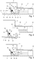
- Fig. 1 shows a device 2 for latching the door 4 of an oxygen mask container 6 in an aircraft cabin.
- the device 2 comprises the door 4 having an inner side 8 and an outer side 10.
- the door 4 is swivably supported on a hinge 12 to swivel downwards to open.
- the size and placement of the door 4, the size of the oxygen mask container 6 as well as the placement of the hinge 12 are not to scale and are merely schematically illustrated to improve understanding the invention.
- a first latching device 14 is attached to the inner side 8 of the door 4 and comprises a through-hole 16, into which a second latching device 18 can be inserted. Due to the fixed installation of the first latching device 14 to the door 4, both elements always move together. Thus, the door 4 is latched if the second latching device 18 engages the first latching device 14.
- the second latching device 18 is exemplarily realized in the form of an elongate element, such as a rod, and has a beveled end 20. It is linearly movable through a first drive unit 22, which may comprise a solenoid or an electric motor. The second latching device 18 is movable linearly along its main extension axis. In the state shown in figure 1 , the second latching device 18 is inserted into the through-hole 16, such that the first and second latching devices 14 and 18 engage. The door 4 thus remains in the closed position.
- a test control device 24 Adjacent to the first latching device 14, a test control device 24 is provided. It comprises a holder 26, which is attached to the inner side 8 of the door 4. On an inner end 28 of the holder 26, a control rod 30 is swivably supported. The control rod 30 comprises a first end 32 and an opposite second end 34. A joint 36 is arranged between the first end 32 and the second end 34, preferably in a center. On the first end 32, a hook element 38 is provided, which protrudes away from the control rod 30. On the second end 34, an indicating tab 40 is provided, which exemplarily comprises an eye-catching color and which protrudes away from the control rod 30.
- a resilient element 42 in the form of a spring is coupled with the control rod 30.
- An opposite end of the resilient element 42 is coupled with the holder 26.
- the arrangement of the resilient element 42 is chosen such that it is parallel to the control rod 30 when the control rod is arranged perpendicularly to the door 4.
- the resilient element 42 is able to pull the first end 32 of the control rod 30 either to a side facing to the first latching device 14 or to an opposite side.
- the controller 30 can assume two distinct stable positions, which are maintained by the resilient element 42.
- the control rod 30, i.e. the test control device 24, is placed in a state that is referred to as a "second stable position", which does not prevent or limit an opening motion of the door 4.
- the opposite state is referred to as "first stable position", which is explained in other drawings.
- a retaining element 44 is shown, which is attached to an inner structure of the oxygen mask container 6, which will be explained in further detail below.
- a second drive unit 46 is provided above the first latching device 14 and will also be explained in further detail below.
- Fig. 2 shows the second latching element 18 in a retracted state, in which it is linearly moved away from the first latching device 14. Here, it has left the through-hole 16, such that the first latching device 14 is not held by the second latching device 18 anymore and the door 4 opens. It is to be understood, that the door 4 can open to a full extent, in which the door 4 swivels down gravity-driven and will align substantially vertically inside the aircraft cabin. Consequently, if the device 2 is in the second stable position, the door 4 can open as usual.
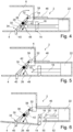
- Fig. 3 shows the device 2 in a state comparable to fig. 1 , wherein the second latching device 2 is about to move in a direction away from the first drive unit 22, such that it is advanced through the through hole 16 towards the test control device 24.
- the beveled end 20 engages the control rod 30 in a region between the joint 36 and the second end 34, such that the control rod 30 swivels about the joint 36 about roughly 90°.
- the control rod 30 assumes the above-mentioned first stable position, in which the hook element 38 is placed directly above the retaining element 44.
- the second latching device 18 is retracted in the direction of the first drive unit 22 again.
- the door 4 can be opened, but the opening degree is restricted through the hook element 38, which engages with the retaining element 44 shortly after the door 4 begins to open. This is particularly useful for testing the function of opening the door 4 without the door 4 having to swivel open completely.
- the mask is completely retained inside the mask container 6 while the door 4 opens only partially, but clearly visibly.
- the second end 34 with the attached indication tab 40 moves opposite to the first end 32. Due to an alignment angle of roughly 135° to the control rod 30 it remains inside the mask container 6 parallel to the closed door 4 in the second stable position. However, when flipping the control rod 30 over to the first stable position, the indication tab 40 is arranged perpendicularly to the door 4. It sticks out through a slit 48 in the door 4 and is clearly visible from outside the mask container 6. The visibility is further increased through the eye-catching color. This prevents maintaining the first stable position in normal operation of the aircraft.
- the device 2 exemplarily comprises a distance sensor 50, which is able to measure a distance between a part of the door 4 in a distance to the hinge 12 and an adjacent lining surface 52.
- a control unit which is not shown herein, may be coupled to a plurality of first drive units 22 and distance sensors 52 to automatically flip over the control rods 30 of all connected devices 2 into the first stable position, initiate opening the doors 4, analyze a distance signal from the distance sensors 50, and save the results.
- the beveled end 20 is designed to engage the through-hole 16, since the trough-hole 16 has only slightly moved downwards.
- the beveled end 20 slides along a contour of the through-hole 16 and the first latching device 14 is pushed upwards to close the door 4 again.
- opening the door 4 can be initiated, but also closing the door 4.
- Reversing the control rod 30 from the first stable position into the second stable position is conducted through the second drive unit 46, which pushes the first end 32 of the control rod 30 away from the retaining element 44. It may thus also be referred to as a reversal actuator.
- the indicating tab 40 moves back into the oxygen mask container 6 and a normal opening function for the door 4 is possible.
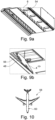
- Figs. 9a and 9b show a hat rack 54 with a plurality of oxygen mask containers 6, which are exemplarily designed for retaining a single oxygen mask each.
- a relatively large number of oxygen mask containers 6 and doors 4 is provided, which need to be tested.
- they may be equipped with the device 2 for latching the door 4 to conduct an automatic testing function.
- Fig. 9b shows the door 4 with the slit 48, which is arranged at an edge region 56 of the door 4.
- the device 2 his left out in this illustration.
- fig. 10 shows an aircraft 58 having an aircraft cabin 60, in which a plurality of oxygen mask containers 6 are installed.
Landscapes
- Engineering & Computer Science (AREA)
- Health & Medical Sciences (AREA)
- Aviation & Aerospace Engineering (AREA)
- Pulmonology (AREA)
- General Health & Medical Sciences (AREA)
- Business, Economics & Management (AREA)
- Emergency Management (AREA)
- Physics & Mathematics (AREA)
- Electromagnetism (AREA)
- Manufacturing & Machinery (AREA)
- Transportation (AREA)
- Respiratory Apparatuses And Protective Means (AREA)
- Testing Resistance To Weather, Investigating Materials By Mechanical Methods (AREA)
Abstract
Description
- The invention relates to a device for latching a door of an oxygen mask container in an aircraft cabin. The invention further relates to a cabin of an aircraft as well as an aircraft having such a cabin.
- Commercial aircraft with a pressurized fuselage and a cabin installed therein usually comprises a plurality of oxygen masks stored inside overhead containers, wherein the containers are opened in emergency cases to allow access to the oxygen masks. During maintenance, the oxygen mask containers are usually checked for their correct function. For this, a door of the oxygen mask container is released through energizing a lock or latch and an operator checks whether all containers open.
- However, concepts exist in which a rather small number of oxygen masks is considered inside a respective container, which may even be a single mask per container. Thus, a large number of oxygen mask containers needs to be checked for their function, which includes visual checking, re-arranging the mask after opening the container, and closing the container again. This is a time consuming and cumbersome process.
- It is thus an object of the invention to provide an oxygen mask container or a device for latching a door of an oxygen mask container that allows a simplified and accelerated testing.
- This object is met by the device for latching a door of an oxygen mask in an aircraft cabin having the features of independent claim 1. Advantageous embodiments and further improvements may be gathered from the sub claims and the following description.
- A device for latching a door of an oxygen mask container in an aircraft cabin is proposed, comprising a door for an oxygen mask container having an inner side, an outer side and a hinge, a first latching device attached to the inner side of the door, a second latching device movable relative to the first latching device to selectively engage or disengage the second latching device, a retaining element attachable to a structural part inside the oxygen mask container, and a test control device arranged on the inner side of the door, wherein the test control device comprises a movable hook element, wherein the test control device is adapted to move the hook element to a first position or to a second position, wherein the hook element is able to engage the retaining element in the first position to restrict an opening degree of the door and wherein the hook element is placed in the second position that when the door is opened, the hook element is moved past the retaining element.
- The gist of the invention lies in the capability of switching a latch of a door of an oxygen mask container into a test mode and a normal operation mode. In the test mode, the respective door can be opened by releasing the latch, but the opening degree of the door is clearly restricted. In other words, a normal opening test sequence for checking the correct function of the latch can be conducted without any modification of the latching principle itself. However, the door does not need to swivel into a completely open position, in which the oxygen mask retained in the oxygen mask container partially falls out and in which the oxygen mask does not have to be re-arranged when closing the door again. However, the restricted motion of the door is still sufficiently significant to be visually checked. A test procedure with a device according to the invention can be accomplished within a clearly reduced time frame, it will also be simplified and clearly less cumbersome.
- The first latching device and the second latching device are designed complementary to each other, such that they can engage or disengage. In the engaged state, the door is latched. In the disengaged state, the door is unlatched and can be opened. If the door is installed to swivel downwards, it will swivel into an open state once the first and second latching devices are disengaged. The process of engaging and disengaging can be accomplished through a drive unit, which moves one of the first or second latching device.
- The first latching device is attached to the inner side of the door and is thus structurally fixed to the door. The second latching device is supported independently from the door. For example, it may be installed on a frame or a wall of the oxygen mask container, in which the door is supported. Preferably the second latching device is connected to a drive unit, which may be coupled with a control unit to release a suitable signal for an emergency opening of the door. The drive unit may comprise a solenoid, an electric motor or the like that is capable of moving the second latching device relative to the first latching device upon receiving the respective signal.
- The test control device can be manipulated to either move into the first position or into the second position. In the second position, a normal operation of the oxygen mask container is possible, i.e. the door will open to a full extent once the first and second latching devices disengage. The hook element then always has a sufficient distance to the retaining element to move past the retaining element. In the first position, the test mode is activated and the door cannot open to a full extent, since the hook element engages with the retaining element.
- Hence, before testing the latch of the door, the hook element is brought into the second position to initiate the test mode. After conducting the test, the hook element can be moved back into the second position, in which the hook element cannot engage the retaining element any more. Thus, the respective door opening degree will not be restricted and it can be opened fully to release the respective mask.
- Moving the hook element can be done by various means, which may include dedicated actuators or by using the drive unit for driving one of the first and second latching device, as explained further below.
- In an advantageous embodiment, the test control device is bi-stable and is adapted to hold the hook element in the first position and the second position automatically. In other word, when the hook element has reached the first position or the second position, an external force, a lock or any other means is not required for holding the hook element in its present position. For achieving this, the hook element may be placed on a mechanical linkage or gear that has two states, which both require an external force to be applied to leave the respective state again. The mechanical linkage or gear may thus resemble a kind of mechanical flip-flop.
- In an advantageous embodiment, the test control device comprises a control rod swivably supported on the inner side of the door and carrying the hook element, wherein the test control device comprises a resilient element coupled with the control rod and the inner side of the door to hold the control rod either in a first state, in which the hook element is in the first position, or a second state, in which the hook element is in the second position. The control rod may thus be flipped between the first state and the second state, wherein the resilient element, e.g. a spring, holds the control rod in the respective state. The control rod is an elongate and preferably rigid element that is supported like a rocker. It may be made from a metallic or plastic material. It may comprise a flat cross-sectional profile, such that it does not take up much installation space of the mask container.
- In an advantageous embodiment, the control rod has a first end and a second end, wherein the control rod is supported on a joint arranged between the first end and the second end, wherein the hook element is arranged on the first end. Thus, when the control rod is flipped from one state into the other, the hook element reaches the first position or the second position, respectively, to assume a desired distance to the retaining element.
- In an advantageous embodiment, the control rod has an indicating tab arranged on the second end, wherein the door has an opening, through which the indicating tab protrudes when the hook element is in the first stable position. The indicating tab is used for signaling a person that a test mode is active. By mechanically coupling the indicating tab to the control rod, the position of the indicating tab is directly depending on the state of the device according to the invention.
- In an advantageous embodiment, the opening is a slit, through which the control rod can swivel. The slit may preferably be dimensioned to allow the control rod and the indicating tab to reach through. The slit should be placed in a position that allows the control rod swivel without interfering with the retained oxygen mask. The control rod may thus comprise a length that exceeds the available space inside the oxygen mask container in an intermediate position between the first position and the second position. When the control rod is flipped between both positions, it partially travels through the slit.
- In an advantageous embodiment, the test control device is arranged in an edge region of the door. Thus, the retaining space for an oxygen mask may be maximized and an interference between the test control device and the oxygen mask is prevented.
- In an advantageous embodiment, the second latching device comprises a linearly moving latching rod, wherein the first latching device comprises a through-hole, into which the latching rod is insertable to latch the door and from which the latching rod is removable to unlatch the door. This is comparable or similar to a common latching mechanism. By moving the second latching device away from the first latching device, the door is unlatched.
- In an advantageous embodiment, the test control device is arranged adjacent to the first latching device, such that the latching rod is able to engage the test control device and move the hook element from the second position into the first position. Thus, an additional active element is not required for initiating the test mode. Simply by moving the already-present second latching device towards the test control device, the test mode is entered. It is preferred if only a dedicated control unit is able to initiate this motion of the latching rod to prevent an undesired activation of the test mode. For example, this may be a test control unit, which is brought into the aircraft merely for conducting a test and only the test control unit is capable of moving the latching rod further through the through-hole to flip the control rod into the first state.
- In an advantageous embodiment, the device further comprises a reversal actuator, which is adapted to move the hook element from the first position into the second position. The test control device thus does not need to be flipped into the normal operation mode manually and the test can be accomplished fully automatic.
- In an advantageous embodiment, the second latching device comprises a beveled end, wherein the second latching device is adapted to engage the first latching device when the door is in a restrictedly opened state, and to advance the first latching device along the beveled end through further moving the second latching device to pull the door into a closed state. Consequently, after conducting the test, the door may even be closed automatically, which further increases the speed of the test procedure.
- In an advantageous embodiment, the device further comprises a door opening sensor attachable to the door or a frame, into which the door is to be arranged, wherein the door opening sensor is adapted to detect an opening degree of the door. The door opening sensor allows to automatically analyze, whether the door opens, e.g. after moving the second latching device away from the first latching device. Handwritten notes are thus not necessary. The door opening sensor may be a distance sensor, such as a capacitive sensor. It may be connected to the above-mentioned test control unit.
- The invention further relates to a cabin of an aircraft, comprising a plurality of oxygen mask containers arranged in an installation inside the cabin, wherein the plurality of oxygen mask containers each comprise a device according to the previous description. The installation may e.g. be a hat rack.
- In an advantageous embodiment, the oxygen mask containers are designed for retaining at least one oxygen mask. It may be possible to provide oxygen mask containers that only retain a single mask.
- Furthermore, the invention relates to an aircraft, comprising at least one cabin of the above description.
- In the following, the attached drawings are used to illustrate exemplary embodiments in more detail. The illustrations are schematic and not to scale. Identical reference numerals refer to identical or similar elements. They show:
-
Fig. 1 and 2 shows a schematic sectional view of a device for latching a door of an oxygen mask container in a closed state (fig. 1 ) and an opened state (fig. 2 ). -
Fig. 3 to 5 shows the device being manipulated into a test mode. -
Fig. 6 and7 show a test opening and closing of the oxygen mask container. -
Figs. 8a to 8c show reversing the device into a normal operation mode. -
Figs. 9a and 9b show a hat rack having oxygen mask containers. -
Fig. 10 shows an aircraft. -
Fig. 1 shows adevice 2 for latching thedoor 4 of anoxygen mask container 6 in an aircraft cabin. Thedevice 2 comprises thedoor 4 having aninner side 8 and anouter side 10. Thedoor 4 is swivably supported on ahinge 12 to swivel downwards to open. The size and placement of thedoor 4, the size of theoxygen mask container 6 as well as the placement of thehinge 12 are not to scale and are merely schematically illustrated to improve understanding the invention. - A
first latching device 14 is attached to theinner side 8 of thedoor 4 and comprises a through-hole 16, into which asecond latching device 18 can be inserted. Due to the fixed installation of thefirst latching device 14 to thedoor 4, both elements always move together. Thus, thedoor 4 is latched if thesecond latching device 18 engages thefirst latching device 14. - The
second latching device 18 is exemplarily realized in the form of an elongate element, such as a rod, and has abeveled end 20. It is linearly movable through afirst drive unit 22, which may comprise a solenoid or an electric motor. Thesecond latching device 18 is movable linearly along its main extension axis. In the state shown infigure 1 , thesecond latching device 18 is inserted into the through-hole 16, such that the first andsecond latching devices door 4 thus remains in the closed position. - Adjacent to the
first latching device 14, atest control device 24 is provided. It comprises aholder 26, which is attached to theinner side 8 of thedoor 4. On aninner end 28 of theholder 26, acontrol rod 30 is swivably supported. Thecontrol rod 30 comprises afirst end 32 and an oppositesecond end 34. A joint 36 is arranged between thefirst end 32 and thesecond end 34, preferably in a center. On thefirst end 32, ahook element 38 is provided, which protrudes away from thecontrol rod 30. On thesecond end 34, an indicatingtab 40 is provided, which exemplarily comprises an eye-catching color and which protrudes away from thecontrol rod 30. - Near the
first end 32, aresilient element 42 in the form of a spring is coupled with thecontrol rod 30. An opposite end of theresilient element 42 is coupled with theholder 26. The arrangement of theresilient element 42 is chosen such that it is parallel to thecontrol rod 30 when the control rod is arranged perpendicularly to thedoor 4. Thus, theresilient element 42 is able to pull thefirst end 32 of thecontrol rod 30 either to a side facing to thefirst latching device 14 or to an opposite side. Thus, thecontroller 30 can assume two distinct stable positions, which are maintained by theresilient element 42. - In the illustration of
fig. 1 , thecontrol rod 30, i.e. thetest control device 24, is placed in a state that is referred to as a "second stable position", which does not prevent or limit an opening motion of thedoor 4. The opposite state is referred to as "first stable position", which is explained in other drawings. - Furthermore, a retaining
element 44 is shown, which is attached to an inner structure of theoxygen mask container 6, which will be explained in further detail below. Asecond drive unit 46 is provided above thefirst latching device 14 and will also be explained in further detail below. -
Fig. 2 shows thesecond latching element 18 in a retracted state, in which it is linearly moved away from thefirst latching device 14. Here, it has left the through-hole 16, such that thefirst latching device 14 is not held by thesecond latching device 18 anymore and thedoor 4 opens. It is to be understood, that thedoor 4 can open to a full extent, in which thedoor 4 swivels down gravity-driven and will align substantially vertically inside the aircraft cabin. Consequently, if thedevice 2 is in the second stable position, thedoor 4 can open as usual. -
Fig. 3 shows thedevice 2 in a state comparable tofig. 1 , wherein thesecond latching device 2 is about to move in a direction away from thefirst drive unit 22, such that it is advanced through the throughhole 16 towards thetest control device 24. As shown infig. 4 , thebeveled end 20 engages thecontrol rod 30 in a region between the joint 36 and thesecond end 34, such that thecontrol rod 30 swivels about the joint 36 about roughly 90°. Thus, thecontrol rod 30 assumes the above-mentioned first stable position, in which thehook element 38 is placed directly above the retainingelement 44. - After flipping the
control rod 30 as shown, thesecond latching device 18 is retracted in the direction of thefirst drive unit 22 again. Now, as shown infig. 6 , thedoor 4 can be opened, but the opening degree is restricted through thehook element 38, which engages with the retainingelement 44 shortly after thedoor 4 begins to open. This is particularly useful for testing the function of opening thedoor 4 without thedoor 4 having to swivel open completely. Hence, the mask is completely retained inside themask container 6 while thedoor 4 opens only partially, but clearly visibly. - When flipping the
control rod 30 from the second position to the first position, thesecond end 34 with the attachedindication tab 40 moves opposite to thefirst end 32. Due to an alignment angle of roughly 135° to thecontrol rod 30 it remains inside themask container 6 parallel to theclosed door 4 in the second stable position. However, when flipping thecontrol rod 30 over to the first stable position, theindication tab 40 is arranged perpendicularly to thedoor 4. It sticks out through aslit 48 in thedoor 4 and is clearly visible from outside themask container 6. The visibility is further increased through the eye-catching color. This prevents maintaining the first stable position in normal operation of the aircraft. - To further simplify a test procedure, the
device 2 exemplarily comprises adistance sensor 50, which is able to measure a distance between a part of thedoor 4 in a distance to thehinge 12 and anadjacent lining surface 52. A control unit, which is not shown herein, may be coupled to a plurality offirst drive units 22 anddistance sensors 52 to automatically flip over thecontrol rods 30 of allconnected devices 2 into the first stable position, initiate opening thedoors 4, analyze a distance signal from thedistance sensors 50, and save the results. - As shown in
fig. 7 , thebeveled end 20 is designed to engage the through-hole 16, since the trough-hole 16 has only slightly moved downwards. By extending thesecond latching device 18 through the through-hole 16 thebeveled end 20 slides along a contour of the through-hole 16 and thefirst latching device 14 is pushed upwards to close thedoor 4 again. Thus, not only opening thedoor 4 can be initiated, but also closing thedoor 4. - Reversing the
control rod 30 from the first stable position into the second stable position is conducted through thesecond drive unit 46, which pushes thefirst end 32 of thecontrol rod 30 away from the retainingelement 44. It may thus also be referred to as a reversal actuator. The indicatingtab 40 moves back into theoxygen mask container 6 and a normal opening function for thedoor 4 is possible. -
Figs. 9a and 9b show ahat rack 54 with a plurality ofoxygen mask containers 6, which are exemplarily designed for retaining a single oxygen mask each. Thus, a relatively large number ofoxygen mask containers 6 anddoors 4 is provided, which need to be tested. For testing, they may be equipped with thedevice 2 for latching thedoor 4 to conduct an automatic testing function.Fig. 9b shows thedoor 4 with theslit 48, which is arranged at anedge region 56 of thedoor 4. For certification purposes, thedevice 2 his left out in this illustration. - Lastly,
fig. 10 shows anaircraft 58 having anaircraft cabin 60, in which a plurality ofoxygen mask containers 6 are installed.
Claims (15)
- Device (2) for latching a door (4) of an oxygen mask container (6) in an aircraft cabin (60), comprising:a door (4) for an oxygen mask container (6) having an inner side (8), an outer side (10) and a hinge (12),a first latching device (14) attached to the inner side (8) of the door (4),a second latching device (18) movable relative to the first latching device (14) to selectively engage or disengage the second latching device (18),a retaining element (44) attachable to a structural part inside the oxygen mask container (6),a test control device (24) arranged on the inner side (8) of the door (4),wherein the test control device (24) comprises a movable hook element (38),wherein the test control device (24) is adapted to move the hook element (38) to a first position or to a second position, wherein the hook element (38) is able to engage the retaining element (44) in the first position to restrict an opening degree of the door (4) and wherein the hook element (38) is placed in the second position that when the door (4) is opened, the hook element (38) is moved past the retaining element (44).
- Device (2) according to claim 1,
wherein the test control device (24) is bi-stable and is adapted to hold the hook element (38) in the first position and the second position automatically. - Device (2) according to claim 1 or 2,wherein the test control device (24) comprises a control rod (30) swivably supported on the inner side (8) of the door (4) and carrying the hook element (38), andwherein the test control device (24) comprises a resilient element (42) coupled with the control rod (30) and the inner side (8) of the door (4) to hold the control rod (30) either in a first state or a second state.
- Device (2) according to claim 3,wherein the control rod (30) has a first end (32) and a second end (34),wherein the control rod (30) is supported on a joint (36) arranged between the first end (32) and the second end (34), andwherein the hook element (38) is arranged on the first end (32).
- Device (2) according to claim 4,wherein the control rod (30) has an indicating tab (40) arranged on the second end (34), andwherein the door (4) has an opening (48), through which the indicating tab (40) protrudes when the hook element (38) is in the first position.
- Device (2) according to claim 5,
wherein the opening (48) is a slit (48), through which the control rod (30) can swivel. - Device (2) according to any of the preceding claims,
wherein the test control device (24) is arranged in an edge region (56) of the door (4). - Device (2) according to any of the preceding claims,wherein the second latching device (18) comprises a linearly moving latching rod (18), andwherein the first latching device (14) comprises a through-hole (16), into which the latching rod (18) is insertable to latch the door (4) and from which the latching rod (18) is removable to unlatch the door (4).
- Device according to claim 8,
wherein the test control device (24) is arranged adjacent to the first latching device (14), such that the latching rod (18) is able to engage the test control device (24) and move the hook element (38) from the second position into the first position. - Device according to any of the preceding claims,
further comprising a reversal actuator (46), which is adapted to move the hook element (38) from the first position into the second position. - Device (2) according to claim 8,wherein the second latching device (18) comprises a beveled end (20), andwherein the second latching device (18) is adapted to engage the first latching device (14) when the door (4) is in a restrictedly opened state, and to advance the first latching device (14) along the beveled end (20) through further moving the second latching device (18) to pull the door (4) into a closed state.
- Device (2) according to any of the preceding claims,further comprising a door opening sensor (50) attachable to the door (4) or a frame, into which the door (4) is to be arranged, andwherein the door opening sensor (50) is adapted to detect an opening degree of the door (4).
- Cabin (60) of an aircraft (58), comprising a plurality of oxygen mask containers (6) arranged in an installation inside the cabin (60), wherein the plurality of oxygen mask containers (6) each comprise a device (2) according to any of the preceding claims.
- Cabin according to claim 13, wherein the oxygen mask containers (6) are designed for retaining at least one oxygen mask.
- Aircraft (58), comprising at least one cabin of claim 13 or 14.
Priority Applications (3)
| Application Number | Priority Date | Filing Date | Title |
|---|---|---|---|
| EP22185218.9A EP4306432B1 (en) | 2022-07-15 | 2022-07-15 | Device for latching a door of an oxygen mask container in an aircraft cabin |
| CN202310859530.0A CN117403967A (en) | 2022-07-15 | 2023-07-13 | Devices for latching, compartments of aircraft and aircraft |
| US18/221,952 US12281496B2 (en) | 2022-07-15 | 2023-07-14 | Device for latching a door of an oxygen mask container in an aircraft cabin |
Applications Claiming Priority (1)
| Application Number | Priority Date | Filing Date | Title |
|---|---|---|---|
| EP22185218.9A EP4306432B1 (en) | 2022-07-15 | 2022-07-15 | Device for latching a door of an oxygen mask container in an aircraft cabin |
Publications (2)
| Publication Number | Publication Date |
|---|---|
| EP4306432A1 true EP4306432A1 (en) | 2024-01-17 |
| EP4306432B1 EP4306432B1 (en) | 2025-09-03 |
Family
ID=82608535
Family Applications (1)
| Application Number | Title | Priority Date | Filing Date |
|---|---|---|---|
| EP22185218.9A Active EP4306432B1 (en) | 2022-07-15 | 2022-07-15 | Device for latching a door of an oxygen mask container in an aircraft cabin |
Country Status (3)
| Country | Link |
|---|---|
| US (1) | US12281496B2 (en) |
| EP (1) | EP4306432B1 (en) |
| CN (1) | CN117403967A (en) |
Families Citing this family (1)
| Publication number | Priority date | Publication date | Assignee | Title |
|---|---|---|---|---|
| CN119466444B (en) * | 2024-11-22 | 2025-09-26 | 合肥工业大学 | Oxygen mask PSU panel lock with stable locking function |
Citations (3)
| Publication number | Priority date | Publication date | Assignee | Title |
|---|---|---|---|---|
| US20080277946A1 (en) * | 2004-09-20 | 2008-11-13 | Telezygology, Inc. | Assemblies for Partial Release |
| US20140001062A1 (en) * | 2012-06-28 | 2014-01-02 | Intertechnique | Container for an oxygen supply unit, device and system of an arrangement of a number of oxygen supply devices, wherein each oxygen supply unit is stored in a container, method of control of a status and/or change of status of a container |
| EP2486958B1 (en) * | 2011-02-10 | 2016-07-13 | Zodiac Aerotechnics | Passenger cabin emergency oxygen device |
-
2022
- 2022-07-15 EP EP22185218.9A patent/EP4306432B1/en active Active
-
2023
- 2023-07-13 CN CN202310859530.0A patent/CN117403967A/en active Pending
- 2023-07-14 US US18/221,952 patent/US12281496B2/en active Active
Patent Citations (3)
| Publication number | Priority date | Publication date | Assignee | Title |
|---|---|---|---|---|
| US20080277946A1 (en) * | 2004-09-20 | 2008-11-13 | Telezygology, Inc. | Assemblies for Partial Release |
| EP2486958B1 (en) * | 2011-02-10 | 2016-07-13 | Zodiac Aerotechnics | Passenger cabin emergency oxygen device |
| US20140001062A1 (en) * | 2012-06-28 | 2014-01-02 | Intertechnique | Container for an oxygen supply unit, device and system of an arrangement of a number of oxygen supply devices, wherein each oxygen supply unit is stored in a container, method of control of a status and/or change of status of a container |
Also Published As
| Publication number | Publication date |
|---|---|
| CN117403967A (en) | 2024-01-16 |
| US12281496B2 (en) | 2025-04-22 |
| US20240018806A1 (en) | 2024-01-18 |
| EP4306432B1 (en) | 2025-09-03 |
Similar Documents
| Publication | Publication Date | Title |
|---|---|---|
| US4470566A (en) | Plug-type aircraft door actuating mechanism | |
| US2748855A (en) | Blow-out safe aircraft doors | |
| US5636814A (en) | Automatic clutch for a door latch handle | |
| CA2344859C (en) | Method and device for closing a door of an aircraft | |
| US8876171B2 (en) | Lock for a luggage box | |
| US6454210B1 (en) | Aircraft vent and cargo door locking mechanism | |
| US11299250B2 (en) | Aircraft privacy door and door frame assembly | |
| US6357806B1 (en) | Door latch device | |
| US4473201A (en) | Canopy-type aircraft cargo door and actuating mechanisms | |
| US12534934B2 (en) | Door latch positioning mechanism | |
| US12281496B2 (en) | Device for latching a door of an oxygen mask container in an aircraft cabin | |
| US20100001136A1 (en) | Aircraft door and method for using the same | |
| US11305860B2 (en) | Aircraft privacy door and door frame assembly | |
| US20200291694A1 (en) | Device for opening a door or flap on a motor vehicle | |
| EP3967595B1 (en) | Overwing exit door system | |
| EP3345826B1 (en) | Modular latch system | |
| CN105857566B (en) | Aircraft cockpit equipped with a safety vent | |
| US20210172211A1 (en) | Motor vehicle lock arrangement | |
| DE256122T1 (en) | EXPLOSION-RESISTANT DOOR LOCKING SYSTEM. | |
| US7290736B2 (en) | Aircraft door | |
| WO1998017528A1 (en) | Plug door operating mechanism | |
| WO1984001761A1 (en) | Canopy-type aircraft cargo door and actuating mechanisms | |
| EP4015382B1 (en) | Sliding latch for galley bay doors | |
| EP0116543B1 (en) | Plug-type aircraft door actuating mechanism | |
| US12428870B2 (en) | Handle assembly for escape hatch |
Legal Events
| Date | Code | Title | Description |
|---|---|---|---|
| PUAI | Public reference made under article 153(3) epc to a published international application that has entered the european phase |
Free format text: ORIGINAL CODE: 0009012 |
|
| STAA | Information on the status of an ep patent application or granted ep patent |
Free format text: STATUS: THE APPLICATION HAS BEEN PUBLISHED |
|
| AK | Designated contracting states |
Kind code of ref document: A1 Designated state(s): AL AT BE BG CH CY CZ DE DK EE ES FI FR GB GR HR HU IE IS IT LI LT LU LV MC MK MT NL NO PL PT RO RS SE SI SK SM TR |
|
| STAA | Information on the status of an ep patent application or granted ep patent |
Free format text: STATUS: REQUEST FOR EXAMINATION WAS MADE |
|
| 17P | Request for examination filed |
Effective date: 20240717 |
|
| RBV | Designated contracting states (corrected) |
Designated state(s): AL AT BE BG CH CY CZ DE DK EE ES FI FR GB GR HR HU IE IS IT LI LT LU LV MC MK MT NL NO PL PT RO RS SE SI SK SM TR |
|
| GRAP | Despatch of communication of intention to grant a patent |
Free format text: ORIGINAL CODE: EPIDOSNIGR1 |
|
| STAA | Information on the status of an ep patent application or granted ep patent |
Free format text: STATUS: GRANT OF PATENT IS INTENDED |
|
| INTG | Intention to grant announced |
Effective date: 20250328 |
|
| GRAS | Grant fee paid |
Free format text: ORIGINAL CODE: EPIDOSNIGR3 |
|
| GRAA | (expected) grant |
Free format text: ORIGINAL CODE: 0009210 |
|
| STAA | Information on the status of an ep patent application or granted ep patent |
Free format text: STATUS: THE PATENT HAS BEEN GRANTED |
|
| AK | Designated contracting states |
Kind code of ref document: B1 Designated state(s): AL AT BE BG CH CY CZ DE DK EE ES FI FR GB GR HR HU IE IS IT LI LT LU LV MC MK MT NL NO PL PT RO RS SE SI SK SM TR |
|
| REG | Reference to a national code |
Ref country code: CH Ref legal event code: EP |
|
| REG | Reference to a national code |
Ref country code: DE Ref legal event code: R096 Ref document number: 602022020602 Country of ref document: DE |
|
| REG | Reference to a national code |
Ref country code: IE Ref legal event code: FG4D |
|
| REG | Reference to a national code |
Ref country code: NL Ref legal event code: MP Effective date: 20250903 |
|
| PG25 | Lapsed in a contracting state [announced via postgrant information from national office to epo] |
Ref country code: NO Free format text: LAPSE BECAUSE OF FAILURE TO SUBMIT A TRANSLATION OF THE DESCRIPTION OR TO PAY THE FEE WITHIN THE PRESCRIBED TIME-LIMIT Effective date: 20251203 |
|
| REG | Reference to a national code |
Ref country code: LT Ref legal event code: MG9D |
|
| PG25 | Lapsed in a contracting state [announced via postgrant information from national office to epo] |
Ref country code: FI Free format text: LAPSE BECAUSE OF FAILURE TO SUBMIT A TRANSLATION OF THE DESCRIPTION OR TO PAY THE FEE WITHIN THE PRESCRIBED TIME-LIMIT Effective date: 20250903 |
|
| PG25 | Lapsed in a contracting state [announced via postgrant information from national office to epo] |
Ref country code: HR Free format text: LAPSE BECAUSE OF FAILURE TO SUBMIT A TRANSLATION OF THE DESCRIPTION OR TO PAY THE FEE WITHIN THE PRESCRIBED TIME-LIMIT Effective date: 20250903 |
|
| PG25 | Lapsed in a contracting state [announced via postgrant information from national office to epo] |
Ref country code: GR Free format text: LAPSE BECAUSE OF FAILURE TO SUBMIT A TRANSLATION OF THE DESCRIPTION OR TO PAY THE FEE WITHIN THE PRESCRIBED TIME-LIMIT Effective date: 20251204 |
|
| PG25 | Lapsed in a contracting state [announced via postgrant information from national office to epo] |
Ref country code: SE Free format text: LAPSE BECAUSE OF FAILURE TO SUBMIT A TRANSLATION OF THE DESCRIPTION OR TO PAY THE FEE WITHIN THE PRESCRIBED TIME-LIMIT Effective date: 20250903 |
|
| PG25 | Lapsed in a contracting state [announced via postgrant information from national office to epo] |
Ref country code: LV Free format text: LAPSE BECAUSE OF FAILURE TO SUBMIT A TRANSLATION OF THE DESCRIPTION OR TO PAY THE FEE WITHIN THE PRESCRIBED TIME-LIMIT Effective date: 20250903 |
|
| PG25 | Lapsed in a contracting state [announced via postgrant information from national office to epo] |
Ref country code: PL Free format text: LAPSE BECAUSE OF FAILURE TO SUBMIT A TRANSLATION OF THE DESCRIPTION OR TO PAY THE FEE WITHIN THE PRESCRIBED TIME-LIMIT Effective date: 20250903 Ref country code: BG Free format text: LAPSE BECAUSE OF FAILURE TO SUBMIT A TRANSLATION OF THE DESCRIPTION OR TO PAY THE FEE WITHIN THE PRESCRIBED TIME-LIMIT Effective date: 20250903 |
|
| PG25 | Lapsed in a contracting state [announced via postgrant information from national office to epo] |
Ref country code: RS Free format text: LAPSE BECAUSE OF FAILURE TO SUBMIT A TRANSLATION OF THE DESCRIPTION OR TO PAY THE FEE WITHIN THE PRESCRIBED TIME-LIMIT Effective date: 20251203 |
|
| PG25 | Lapsed in a contracting state [announced via postgrant information from national office to epo] |
Ref country code: ES Free format text: LAPSE BECAUSE OF FAILURE TO SUBMIT A TRANSLATION OF THE DESCRIPTION OR TO PAY THE FEE WITHIN THE PRESCRIBED TIME-LIMIT Effective date: 20250903 |
|
| REG | Reference to a national code |
Ref country code: AT Ref legal event code: MK05 Ref document number: 1832794 Country of ref document: AT Kind code of ref document: T Effective date: 20250903 |
|
| PG25 | Lapsed in a contracting state [announced via postgrant information from national office to epo] |
Ref country code: NL Free format text: LAPSE BECAUSE OF FAILURE TO SUBMIT A TRANSLATION OF THE DESCRIPTION OR TO PAY THE FEE WITHIN THE PRESCRIBED TIME-LIMIT Effective date: 20250903 |
|
| PG25 | Lapsed in a contracting state [announced via postgrant information from national office to epo] |
Ref country code: SM Free format text: LAPSE BECAUSE OF FAILURE TO SUBMIT A TRANSLATION OF THE DESCRIPTION OR TO PAY THE FEE WITHIN THE PRESCRIBED TIME-LIMIT Effective date: 20250903 |
|
| PG25 | Lapsed in a contracting state [announced via postgrant information from national office to epo] |
Ref country code: AT Free format text: LAPSE BECAUSE OF FAILURE TO SUBMIT A TRANSLATION OF THE DESCRIPTION OR TO PAY THE FEE WITHIN THE PRESCRIBED TIME-LIMIT Effective date: 20250903 |
|
| PG25 | Lapsed in a contracting state [announced via postgrant information from national office to epo] |
Ref country code: IT Free format text: LAPSE BECAUSE OF FAILURE TO SUBMIT A TRANSLATION OF THE DESCRIPTION OR TO PAY THE FEE WITHIN THE PRESCRIBED TIME-LIMIT Effective date: 20250903 |
|
| PG25 | Lapsed in a contracting state [announced via postgrant information from national office to epo] |
Ref country code: IS Free format text: LAPSE BECAUSE OF FAILURE TO SUBMIT A TRANSLATION OF THE DESCRIPTION OR TO PAY THE FEE WITHIN THE PRESCRIBED TIME-LIMIT Effective date: 20260103 |
|
| PG25 | Lapsed in a contracting state [announced via postgrant information from national office to epo] |
Ref country code: CZ Free format text: LAPSE BECAUSE OF FAILURE TO SUBMIT A TRANSLATION OF THE DESCRIPTION OR TO PAY THE FEE WITHIN THE PRESCRIBED TIME-LIMIT Effective date: 20250903 Ref country code: PT Free format text: LAPSE BECAUSE OF FAILURE TO SUBMIT A TRANSLATION OF THE DESCRIPTION OR TO PAY THE FEE WITHIN THE PRESCRIBED TIME-LIMIT Effective date: 20260105 |
|
| PG25 | Lapsed in a contracting state [announced via postgrant information from national office to epo] |
Ref country code: SK Free format text: LAPSE BECAUSE OF FAILURE TO SUBMIT A TRANSLATION OF THE DESCRIPTION OR TO PAY THE FEE WITHIN THE PRESCRIBED TIME-LIMIT Effective date: 20250903 Ref country code: EE Free format text: LAPSE BECAUSE OF FAILURE TO SUBMIT A TRANSLATION OF THE DESCRIPTION OR TO PAY THE FEE WITHIN THE PRESCRIBED TIME-LIMIT Effective date: 20250903 |