EP4306429A1 - Air data probe electronics housing with thermal isolating features - Google Patents
Air data probe electronics housing with thermal isolating features Download PDFInfo
- Publication number
- EP4306429A1 EP4306429A1 EP23184010.9A EP23184010A EP4306429A1 EP 4306429 A1 EP4306429 A1 EP 4306429A1 EP 23184010 A EP23184010 A EP 23184010A EP 4306429 A1 EP4306429 A1 EP 4306429A1
- Authority
- EP
- European Patent Office
- Prior art keywords
- wall
- housing
- probe
- air data
- data probe
- Prior art date
- Legal status (The legal status is an assumption and is not a legal conclusion. Google has not performed a legal analysis and makes no representation as to the accuracy of the status listed.)
- Granted
Links
Images


Classifications
-
- B—PERFORMING OPERATIONS; TRANSPORTING
- B64—AIRCRAFT; AVIATION; COSMONAUTICS
- B64D—EQUIPMENT FOR FITTING IN OR TO AIRCRAFT; FLIGHT SUITS; PARACHUTES; ARRANGEMENT OR MOUNTING OF POWER PLANTS OR PROPULSION TRANSMISSIONS IN AIRCRAFT
- B64D15/00—De-icing or preventing icing on exterior surfaces of aircraft
- B64D15/20—Means for detecting icing or initiating de-icing
-
- G—PHYSICS
- G01—MEASURING; TESTING
- G01P—MEASURING LINEAR OR ANGULAR SPEED, ACCELERATION, DECELERATION, OR SHOCK; INDICATING PRESENCE, ABSENCE, OR DIRECTION, OF MOVEMENT
- G01P5/00—Measuring speed of fluids, e.g. of air stream; Measuring speed of bodies relative to fluids, e.g. of ship, of aircraft
- G01P5/14—Measuring speed of fluids, e.g. of air stream; Measuring speed of bodies relative to fluids, e.g. of ship, of aircraft by measuring differences of pressure in the fluid
- G01P5/16—Measuring speed of fluids, e.g. of air stream; Measuring speed of bodies relative to fluids, e.g. of ship, of aircraft by measuring differences of pressure in the fluid using Pitot tubes, e.g. Machmeter
- G01P5/165—Arrangements or constructions of Pitot tubes
-
- B—PERFORMING OPERATIONS; TRANSPORTING
- B64—AIRCRAFT; AVIATION; COSMONAUTICS
- B64D—EQUIPMENT FOR FITTING IN OR TO AIRCRAFT; FLIGHT SUITS; PARACHUTES; ARRANGEMENT OR MOUNTING OF POWER PLANTS OR PROPULSION TRANSMISSIONS IN AIRCRAFT
- B64D15/00—De-icing or preventing icing on exterior surfaces of aircraft
- B64D15/12—De-icing or preventing icing on exterior surfaces of aircraft by electric heating
-
- B—PERFORMING OPERATIONS; TRANSPORTING
- B64—AIRCRAFT; AVIATION; COSMONAUTICS
- B64D—EQUIPMENT FOR FITTING IN OR TO AIRCRAFT; FLIGHT SUITS; PARACHUTES; ARRANGEMENT OR MOUNTING OF POWER PLANTS OR PROPULSION TRANSMISSIONS IN AIRCRAFT
- B64D43/00—Arrangements or adaptations of instruments
-
- B—PERFORMING OPERATIONS; TRANSPORTING
- B64—AIRCRAFT; AVIATION; COSMONAUTICS
- B64D—EQUIPMENT FOR FITTING IN OR TO AIRCRAFT; FLIGHT SUITS; PARACHUTES; ARRANGEMENT OR MOUNTING OF POWER PLANTS OR PROPULSION TRANSMISSIONS IN AIRCRAFT
- B64D43/00—Arrangements or adaptations of instruments
- B64D43/02—Arrangements or adaptations of instruments for indicating aircraft speed or stalling conditions
-
- G—PHYSICS
- G01—MEASURING; TESTING
- G01K—MEASURING TEMPERATURE; MEASURING QUANTITY OF HEAT; THERMALLY-SENSITIVE ELEMENTS NOT OTHERWISE PROVIDED FOR
- G01K13/00—Thermometers specially adapted for specific purposes
- G01K13/02—Thermometers specially adapted for specific purposes for measuring temperature of moving fluids or granular materials capable of flow
- G01K13/028—Thermometers specially adapted for specific purposes for measuring temperature of moving fluids or granular materials capable of flow for use in total air temperature [TAT] probes
Definitions
- the present disclosure relates generally to air data probes on an aircraft, and more particularly to an air data probe electronics housing with thermal isolating features.
- Some aircraft air data probes are heated to prevent rain, ice, or other moisture from attaching to the probe, which could negatively impact the functionality of the air data probe. In many cases, the heat is elevated to extremely hot temperatures to ensure there is no ice accretion on the air data probe during flight of the aircraft. However, there are materials and components within the air data probes in which excess heat is detrimental. As such, there is a need for preventing damage to the materials and components positioned within the heated air data probes.
- an air data probe includes a body comprising an inlet fluidly coupled to an outlet.
- a heating element is positioned within the body of the air data probe, and the heating element is configured to increase a temperature of the body.
- a sensing probe is positioned within the body, and the sensing probe includes a sensing base coupling the sensing probe to the body.
- a housing is positioned within and coupled to the body.
- the housing includes a housing body including an upper surface, a lower surface, an inner surface, an outer surface, an inner wall, and an outer wall. The inner wall is offset from the outer wall such that a gap is positioned between the inner wall and the outer wall.
- a housing for surrounding electrical components within an air data probe configured to gather data during flight of an aircraft.
- the housing includes an upper surface, a lower surface, an inner surface, an outer surface, a rim positioned adjacent the upper surface, and a lower body positioned adjacent the lower surface.
- An inner wall is offset from an outer wall such that a gap is positioned between the inner wall and the outer wall. The inner wall and the outer wall converge and are coupled adjacent the lower body of the housing body.
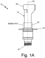
- FIG. 1A is a side view of air data probe 10 used on an aircraft (not shown).
- FIG. 1B is a partial cross-sectional view of housing 12 positioned within air data probe 10 taken along Section A-A of FIG. 1A .
- FIGS. 1A-1B will be discussed together.
- air data probe 10 will be referred to as probe 10, but it is to be understood that probe 10 is referring to air data probe 10.
- Probe 10 is a device which detects or measures a physical property and records, initiates, or otherwise responds to the detected or measured physical property.
- probe 10 can be used to detect the total air temperature, air pressure, air velocity, and/or air density, among other properties not specifically described, during flight of an aircraft.
- probe 10 can be positioned at the nose cone of an aircraft such that probe 10 is positioned partially within the skin of the aircraft and partially outside the skin of the aircraft.
- probe 10 can experience harsh operating conditions including, but not limited to low operating temperatures, ice, rain, sleet, snow, etc.
- probe 10 can be heated to prevent ice, rain, or other precipitation from accumulating on probe 10 during flight of the aircraft. Heating probe 10 can melt ice on probe 10, allowing the precipitation to blow off probe 10 during flight conditions. Further, heating probe 10 can facilitate evaporation of any precipitation on probe 10 during flight conditions. Probe 10 is configured to gather air data during flight of the aircraft, providing the pilots of the aircraft critical information during flight conditions. As such, it is important that probe 10 is functioning properly and providing the pilots of the aircraft accurate information.
- probe 10 includes body 14, flange 16, electrical connector 18, inlet 20, and outlet 22.
- Body 14 is the main structure of probe 10 that protects the components within probe 10 from environmental conditions.
- body 14 can be constructed from at least one metallic material.
- body 14 can be constructed from a ceramic material, a polymeric material, and/or a composite material. With that said, the following discussion with focus on an embodiment in which body 14 is constructed from a metallic material.
- Body 14 includes inlet 20 positioned at a distal end of probe 10 and outlet 22 positioned generally at a central portion of probe 10.
- Inlet 20 is positioned at a first distal end of probe 10. More specifically, inlet 20 is positioned at the distal end of probe 10 positioned outside the skin of the aircraft.
- Inlet 20 can be an aperture extending through body 14, allowing air from outside the aircraft to enter and flow through inlet 20 into body 14. The air that flows through inlet 20 proceeds by flowing through body 14 and then exits body 14 by flowing outwards through outlet 22.
- Outlet 22 can be an aperture that extends through body 14, allowing air from within body 14 to flow out through outlet 22 to exit probe 10. In some examples, as shown, outlet 22 can be positioned generally at the central portion of probe 10 adjacent flange 16.
- Flange 16 is positioned adjacent outlet 22 generally at a central portion of probe 10. Flange 16 extends outwards from the main portions of body 14 and flange 16 extends fully around an outer surface of body 14 of probe 10. As such, flange 16 is a flat rim or collar extending outwards from body 14 around an exterior of body 14. In some examples, flange 16 can have a circular cross-section viewing in the axial direction along probe 10. In other examples, flange 16 can have a cross-section of any geometric shape. Flange 16 is the feature of probe 10 that separates the portions of probe 10 positioned within and positioned outside the skin of an aircraft.
- the portion of probe 10 including inlet 20 and outlet 22 is positioned on the outside of the skin of the aircraft and the portion of probe 10 including electrical connector 18 is positioned on the inside of the skin of the aircraft.
- Electrical connector 18 can be any electrical connector that creates an electrical connection between probe 10 and electronics on an aircraft. As shown in FIG. 1A , in some examples electrical connector 18 can include a threaded connection for securing probe 10 to an aircraft electrical system.
- probe 10 also includes heating element 24, sensing probe 26, sensing base 28, electrical wires 30, electrical leads 32, housing 12, and potting 34, each of which are positioned within body 14 of housing 12.
- probe 10 includes one heating element 24 wrapped around an outer surface of probe 10.
- probe 10 can include more than one heating element 24.
- heating element 24 is wrapped around an outer surface of probe 10 to facilitate melting of ice or evaporation of fluid on outer surfaces of probe 10.
- Heating element 24 can be an electrical resistance heating element that increases in temperature when an electrical current is transferred to the electrical resistance heating element.
- heating element 24 can be electrical wires or electrical pads, among other options, that increase in temperature when an electrical current is transferred to heating element 24, such that heating element 24 increases the temperature of body 14.
- Sensing probe 26 and sensing base 28 are components of probe 10 positioned within body 14 and generally aligned with a central axis of probe 10.
- Sensing probe 26 is the component of probe 10 which detects or measures a physical property of the air flowing through probe 10. More specifically, air from outside the aircraft flows through inlet 20 into body 14 and follows the flow path, indicated by the arrows in FIG. 1B , through body 14 to outlet 22. As such, the air flowing through probe 10 flows past sensing probe 26 within body 14 and sensing probe 26 can gather the desired data from the air flow before the air exits probe 10 through outlet 22.
- Sensing probe 26 is coupled to sensing base 28 to secure sensing probe 26 in a fixed position during operation of probe 10. Further, sensing base 28 is coupled to internal surfaces or features of body 14 to secure both sensing base 28 and sensing probe 26 in a fixed position during operation of probe 10 on an aircraft.
- Electrical wires 30 are electrically coupled to and extend from a distal end of sensing probe 26 positioned within housing 12 of probe 10. Electrical wires 30 are configured to transfer data gathered by sensing probe 26 to an electrical system and/or a controller on an aircraft. More specifically, a plurality of electrical wires 30 are electrically coupled to a plurality of electrical leads 32, and the plurality of electrical leads 32 are coupled to electrical connector 18 of probe 10. As such, air data gathered by sensing probe 26 is transferred through electrical wires 30, through electrical leads 32, through electrical connector 18, and to an electrical controller system of an aircraft.
- electrical wires 30, electrical leads 32, and electrical connector 18 allow the transfer of data from sensing probe 26 to an aircraft, and breaking the electrical connection between any of the components can prevent the transfer of data from sensing probe 26 to an aircraft. As such, maintaining the electrical connection between electrical wires 30, electrical leads 32, and electrical connector 18 is critical to maintaining proper functioning of probe 10.
- Housing 12 is positioned within body 14 of probe 10 and housing 12 is coupled to body 14 of probe 10.
- housing 12 can be coupled to internal surfaces or features of body 14 through a welded connection.
- housing 12 can be constructed from a metallic material.
- housing 12 can be constructed from a non-metallic material and housing 12 can be coupled to body 14 through an adhesive, a mechanical feature, or a fastener, among other options.
- housing 12 can be axially aligned with a central axis of probe 10. Therefore, in some examples, housing 12 can be positioned concentric with body 14 of probe 10. Housing 12 is fixedly positioned within body 14 of probe 10 and adjacent sensing base 28 of probe 10.
- housing 12 is positioned such that housing 12 surrounds the plurality of electrical wires 30 extending from sensing probe 26. More specifically, housing 12 is positioned such that housing 12 surrounds a connection point between the plurality of electrical wires 30 and the plurality of electrical leads 32 such that the plurality of electrical wires 30 and the plurality of electrical leads 32 extend within a center opening within housing 12. In addition, the connection point between the plurality of electrical wires 30 and the plurality of electrical leads 32 is encompassed by potting 34.
- Potting 34 is positioned within an inner surface of housing 12 and potting 34 is positioned adjacent an upper surface of housing 12. In some examples, as shown in FIG. 1B , potting 34 extends only a partial distance from an upper surface of housing 12 towards a lower surface of housing 12. In other examples, potting 34 can extend a full distance from an upper surface of housing 12 to a lower surface of housing 12. Further, potting 34 can encompass and fully surround the connection point between the plurality of electrical wires 30 and the plurality of electrical leads 32. As such, potting 34 is configured to aid in securing the connection between the plurality of electrical wires 30 and the plurality of electrical leads 32.
- potting 34 can provide vibration support to the plurality of electrical wires 30 and the plurality of electrical leads 32, and potting 34 can act as an electrical isolator between the plurality of electrical wires 30, the plurality of electrical leads 32, and housing 12.
- potting 34 can be constructed from a high-temperature epoxy material, such that potting 34 is introduced into housing 12 as a fluid and then solidifies to produce the vibration support and electrical isolation.
- potting 34 can be constructed from a high-temperature epoxy material, the heat produced by heating element 24 of probe 10 can have undesirable effects on potting 34.
- some high-temperature epoxy materials are designed to prevent melting under high temperatures, but if a high enough temperature is reached the high-temperature epoxy material could crack due to its brittle material properties.
- potting 34 is likely to have different material properties than the metallic components surrounding potting 34, such as housing 12 and body 14 of probe 10. Therefore, potting 34 is likely to have a different coefficient of thermal expansion than housing 12 and when heat is applied to housing 12 and potting 34, the components will expand at differing rates.
- High-temperature epoxy material generally expand at a greater rate than metallic materials due when heat is applied to the components.
- housing 12 includes features preventing damage to the plurality of electrical wires 30 and the plurality of electrical leads 32.
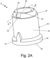
- FIG. 2A is a perspective view of housing 12 shown in FIG. 1B .
- FIG. 2B is a cross-sectional view of housing 12 taken along Section B-B of FIG. 2A .
- Housing 12 includes housing body 36 including upper surface 38, lower surface 40, inner surface 42, outer surface 44, rim 46, lower body 48, first alignment feature 50, second alignment feature 52, inner wall 54, and outer wall 56.
- Upper surface 38 is a surface at a first distal end of housing 12 and lower surface 40 is a surface at a second distal end of housing 12, opposite first distal end.
- inner surface 42 is the surface positioned within the walls constituting housing 12 and outer surface 44 is the surface positioned outside the walls constituting housing 12.
- housing 12 includes a circular cross-section in the axial direction such that housing 12 has a generally cylindrical shape. In other examples, housing 12 can have an axial cross-section of any geometrical shape.
- Rim 46 is positioned adjacent upper surface 38 of housing 12 and rim 46 extends fully around a perimeter or circumference of housing 12, about central axis CL of housing 12. Rim 46 is a ledge or cutout that extends inwards from outer surface 44 towards central axis CL of housing 12. As such, an inner surface or edge of rim 46 has a smaller diameter than outer surface 44 of housing 12. Rim 46 is configured to aid in the proper positioning of housing 12 within body 14 of probe 10. Lower body 48 is positioned adjacent lower surface 40 of housing 12 and lower body 48 extends fully around outer surface 44 of housing 12, about central axis CL of housing 12. Lower body 48 is a portion of housing 12 that extends outwards from outer surface 44 of housing 12 away from central axis CL of housing 12.
- lower body 48 has a larger diameter than outer surface 44 of housing 12. Further, in the example shown, an outer diameter of rim 46 is less than an outer diameter of lower body 48. Lower body 48 having a larger diameter than rim 46 and outer surface 44 aids in housing 12 being correctly positioned within body 14 of probe 10.
- housing body 36 also includes first alignment feature 50 and second alignment feature 52.
- First alignment feature 50 is positioned adjacent rim 46 of housing 12 and second alignment feature 52 is positioned adjacent lower body 48 of housing 12.
- First alignment feature 50 is a cutout or indent extending into housing body 36 adjacent rim 46 and upper surface 38 of housing 12.
- Second alignment feature 52 is a protrusion extending outwards from outer surface 44 of housing body 36.
- first alignment feature 50 has a generally rectangular shape, but in another example first alignment feature 50 could have any geometric shape.
- second alignment feature 52 is a generally triangular shaped protrusion, but in another example second alignment feature 52 could be any geometric shaped protrusion.
- First alignment feature 50 and second alignment feature 52 are vertically aligned with respect to a vertical plane extending from lower surface 40 of housing 12 to upper surface 38 of housing 12. First alignment feature 50 and second alignment feature 52 aid in housing 12 being correctly positioned within body 14 of probe 10. More specifically, first alignment feature 50 and second alignment feature 52 are configured to mate with mating features of body 14 of probe 10 to ensure housing 12 is oriented in the correct position while being inserted into body 14 of probe 10.
- housing 12 includes inner wall 54 and outer wall 56.
- Inner wall 54 is generally a hollow cylinder extending from lower body 48 to upper surface 38 of housing 12. More specifically, inner wall 54 extends a partial distance from lower body 48 and outer wall 56 of housing 12 towards central axis CL and then inner wall 54 angles upward such that a portion of inner wall 54 is parallel with central axis CL. In the example shown, the portion of inner wall 54 parallel with central axis CL is a hollow cylinder with a circular cross-section. In another example, inner wall 54 can have a cross-section of any geometric shape.
- Outer wall 56 is generally a hollow cylinder that extends from lower body 48 to upper surface 38.
- Outer wall 56 is oriented parallel to central axis CL and outer wall 56 is concentric with inner wall 54.
- outer wall 56 is a hollow cylinder with a circular cross-section.
- outer wall 56 can have a cross-section of any geometric shape.
- Outer wall 56 fully surrounds an outer circumference of inner wall 54. More specifically, inner wall 54 is offset from outer wall 56 in a direction towards central axis CL such that a gap is positioned between inner wall 54 and outer wall 56. Further, a portion of inner wall 54 converges with outer wall 56 such that inner wall 54 and outer wall 56 are coupled adjacent lower body 48 of housing 12.
- the gap between inner wall 54 and outer wall 56 is an air gap in which air or other gas is free to flow within, discussed further below.
- inner wall 54 and outer wall 56 have equal thicknesses. In another example, inner wall 54 and outer wall 56 can have differing thicknesses. The thickness of inner wall 54 and outer wall 56 can differ depending on requisite physical properties of housing 12.
- Central aperture 58 is formed by inner surface 42 of inner wall 54. Central aperture 58 is axially aligned with central axis CL and central aperture 58 extends through housing 12 from upper surface 38 to lower surface 40 of housing 12. Referring again to FIG. 1B , central aperture 58 is configured to allow a distal end of sensing probe 26, electrical wires 30, and electrical leads 32 to be positioned within and extend at least partially through central aperture 58. In the example shown, central aperture 58 has a circular cross-section in the axial direction of central axis CL. In other examples, central aperture 58 could have any geometric shape as its cross-section in the axial direction of central axis CL.
- Housing 12 also includes a plurality of apertures 60 extending through upper surface 38 of housing body 36 to the gap positioned between inner wall 54 and outer wall 56.
- the plurality of apertures 60 are configured to allow air or other gas to flow into and out of the gap positioned between inner wall 54 and outer wall 56.
- Housing 12 with inner wall 54 and outer wall 56 can be manufactured using an additive manufacturing process, such as a laser powder bed fusion process. As such, housing 12 is grown in a vertical direction starting at lower surface 40 and finishing at upper surface 38. In some examples, housing 12 can be constructed from a metallic material. In other examples, housing 12 can be constructed from a ceramic material, a polymeric material, and/or a composite material. The plurality of apertures 60 positioned adjacent upper surface 38 of housing 12 also aid in removing any excess material from the gap between inner wall 54 and outer wall 56 that may have accumulated within the gap during the additive manufacturing process.
- an additive manufacturing process such as a laser powder bed fusion process.
- housing 12 is grown in a vertical direction starting at lower surface 40 and finishing at upper surface 38.
- housing 12 can be constructed from a metallic material.
- housing 12 can be constructed from a ceramic material, a polymeric material, and/or a composite material.
- the plurality of apertures 60 positioned adjacent upper surface 38 of housing 12 also aid in removing any excess material from
- housing 12 is pressed into body 14, housing 12 is then welded or otherwise coupled to body 14, and electrical wires 30 are soldered or otherwise electrically coupled to electrical leads 32. Then a liquefied potting 34 is dispensed within inner surface 42 of inner wall 54 of housing 12 and the potting 34 is subsequently cured and allowed to harden within inner surface 42 of inner wall 54 of housing 12. The cured potting 34 positioned within inner surface 42 of inner wall 54 encompasses and fully surrounds the connection point between electrical wires 30 and electrical leads 32.
- probe 10 is heated through heating element 24 and potting 34 will increase in temperature and expand in volume.
- the gap positioned between inner wall 54 and outer wall 56 acts as a thermal isolator and the air within the gap absorbs some of the heat before the heat can reach potting 34.
- the gap thermal isolator
- potting 34 being positioned only within inner surface 42 of inner wall 54 results in potting 34 having less total volume, as compared to a housing without the inner wall, the outer wall, and the air gap between the walls.
- the reduced volume of potting 34 within housing 12 further minimizes the expansion of potting 34 within housing 12, as compared to a potting within a housing without the inner wall, outer wall, and air gap.
- probe 10 including inner wall 54, outer wall 56, and the air gap between the walls within housing 12 hinders potting 34 from growing outside its intended adhesion area. In turn, this prevents potting 34 from expanding too much and breaking apart the electrical connection between electrical wires 30 and electrical leads 32, ensuring the electronic components within probe 10 remain functional during heating of probe 10. Protecting the electronic components within probe 10 makes probe 10 more robust and allows probe 10 to continue working accurately during heating conditions. Probe 10 including inner wall 54, outer wall 56, and the air gap between the walls prevents damage to the electronic components within probe 10 by ensuring the heat induced on probe 10 does not have detrimental effects to the electronic components. As such, probe 10 can be heated to prevent rain and ice buildup and probe 10 will continue transferring accurate data to the pilot and the co-pilot during flight of the aircraft.
- An air data probe comprising: a body comprising an inlet fluidly coupled to an outlet; a heating element positioned within the body of the air data probe, wherein the heating element is configured to increase a temperature of the body; a sensing probe positioned within the body, wherein the sensing probe includes a sensing base coupling the sensing probe to the body; and a housing positioned within and coupled to the body, wherein the housing includes: a housing body including an upper surface, a lower surface, an inner surface, an outer surface, an inner wall, and an outer wall; wherein the inner wall is offset from the outer wall such that a gap is positioned between the inner wall and the outer wall.
- the air data probe of the preceding paragraph can optionally include, additionally and/or alternatively, any one or more of the following features, configurations and/or additional components:
- the housing surrounds a plurality of electrical wires extending from the sensing probe, and wherein the plurality of electrical wires are electrically coupled to a plurality of electrical leads.
- a connection point between the plurality of electrical wires and the plurality of electrical leads is encompassed by a potting, and wherein the potting is positioned within the inner wall of the housing.
- the potting extends a partial distance from the upper surface of the housing towards the lower surface of the housing, and wherein the potting is constructed from a high-temperature epoxy material.
- a plurality of apertures extend through the upper surface of the housing body to the gap positioned between the inner wall and the outer wall of the housing body.
- the inner wall and the outer wall of the housing body have equal thicknesses; and the outer wall of the housing body fully surrounds a circumference of the inner wall of the housing body.
- the inner wall is a hollow cylinder extending from the lower body to the upper surface
- the outer wall is a hollow cylinder extending from the lower body to the upper surface, and wherein the inner wall and the outer wall are concentric.
- a flange extending around an outer surface of the body and an electrical connector positioned at a distal end of the air data probe opposite the inlet of the air data probe.
- the housing is coupled to the body through a welded connection.
- the air data probe is a total air temperature probe configured to measure air temperature outside an outer skin of an aircraft.
- a housing for surrounding electrical components within an air data probe configured to gather data during flight of an aircraft comprising: a housing body including an upper surface, a lower surface, an inner surface, an outer surface, a rim positioned adjacent the upper surface, and a lower body positioned adjacent the lower surface; and an inner wall offset from an outer wall such that a gap is positioned between the inner wall and the outer wall, wherein the inner wall and the outer wall converge and are coupled adjacent the lower body of the housing body.
- the housing of the preceding paragraph can optionally include, additionally and/or alternatively, any one or more of the following features, configurations and/or additional components:
- a first alignment feature and a second alignment feature wherein the first alignment feature is positioned adjacent the rim of the housing body, and wherein the second alignment feature is positioned adjacent the lower body of the housing body.
- the first alignment feature and the second alignment feature are vertically aligned with respect to a vertical plane extending from the lower surface to the upper surface of the housing body; the first alignment feature is an indentation extending into the housing body; and the second alignment feature is a protrusion extending outwards from the outer surface of the housing body.
- a plurality of apertures extend through the upper surface of the housing body to the gap positioned between the inner wall and the outer wall.
- the inner wall and the outer wall have equal thicknesses.
- the outer wall fully surrounds a circumference of the inner wall.
- the inner wall is a hollow cylinder extending from the lower body to the upper surface
- the outer wall is a hollow cylinder extending from the lower body to the upper surface, and wherein the inner wall and the outer wall are concentric.
- the inner wall extends a partial distance from the outer wall of the housing towards a central axis of the housing, such that an aperture aligned with the central axis extends through the housing from the upper surface to the lower surface of the housing.
- the housing includes a circular cross-section, such that the housing is generally cylindrical in shape.
- An outer diameter of the rim is less than an outer diameter of the lower body.
Landscapes
- Engineering & Computer Science (AREA)
- Aviation & Aerospace Engineering (AREA)
- Physics & Mathematics (AREA)
- General Physics & Mathematics (AREA)
- Measuring Temperature Or Quantity Of Heat (AREA)
- Arrangements For Transmission Of Measured Signals (AREA)
Abstract
Description
- The present disclosure relates generally to air data probes on an aircraft, and more particularly to an air data probe electronics housing with thermal isolating features.
- Some aircraft air data probes are heated to prevent rain, ice, or other moisture from attaching to the probe, which could negatively impact the functionality of the air data probe. In many cases, the heat is elevated to extremely hot temperatures to ensure there is no ice accretion on the air data probe during flight of the aircraft. However, there are materials and components within the air data probes in which excess heat is detrimental. As such, there is a need for preventing damage to the materials and components positioned within the heated air data probes.
- According to one aspect of the disclosure, an air data probe is disclosed. The air data probe includes a body comprising an inlet fluidly coupled to an outlet. A heating element is positioned within the body of the air data probe, and the heating element is configured to increase a temperature of the body. A sensing probe is positioned within the body, and the sensing probe includes a sensing base coupling the sensing probe to the body. A housing is positioned within and coupled to the body. The housing includes a housing body including an upper surface, a lower surface, an inner surface, an outer surface, an inner wall, and an outer wall. The inner wall is offset from the outer wall such that a gap is positioned between the inner wall and the outer wall.
- According to another aspect of the disclosure, a housing for surrounding electrical components within an air data probe configured to gather data during flight of an aircraft is disclosed. The housing includes an upper surface, a lower surface, an inner surface, an outer surface, a rim positioned adjacent the upper surface, and a lower body positioned adjacent the lower surface. An inner wall is offset from an outer wall such that a gap is positioned between the inner wall and the outer wall. The inner wall and the outer wall converge and are coupled adjacent the lower body of the housing body.
-
-
FIG. 1A is a side view of an exemplary air data probe used on an aircraft. -
FIG. 1B is a partial cross-sectional view of a housing within the exemplary air data probe taken along Section A-A ofFIG. 1A . -
FIG. 2A is a perspective view of an exemplary housing. -
FIG. 2B is a cross-sectional view of the exemplary housing taken along Section B-B ofFIG. 2A . -
FIG. 1A is a side view ofair data probe 10 used on an aircraft (not shown).FIG. 1B is a partial cross-sectional view ofhousing 12 positioned withinair data probe 10 taken along Section A-A ofFIG. 1A .FIGS. 1A-1B will be discussed together. Further, hereinafter,air data probe 10 will be referred to asprobe 10, but it is to be understood thatprobe 10 is referring toair data probe 10.Probe 10 is a device which detects or measures a physical property and records, initiates, or otherwise responds to the detected or measured physical property. In some examples,probe 10 can be used to detect the total air temperature, air pressure, air velocity, and/or air density, among other properties not specifically described, during flight of an aircraft. Further, in some examples,probe 10 can be positioned at the nose cone of an aircraft such thatprobe 10 is positioned partially within the skin of the aircraft and partially outside the skin of the aircraft. - Since a portion of
probe 10 is positioned outside the skin of the aircraft,probe 10 can experience harsh operating conditions including, but not limited to low operating temperatures, ice, rain, sleet, snow, etc. In some examples, to ensure proper functionality ofprobe 10,probe 10 can be heated to prevent ice, rain, or other precipitation from accumulating onprobe 10 during flight of the aircraft.Heating probe 10 can melt ice onprobe 10, allowing the precipitation to blow offprobe 10 during flight conditions. Further,heating probe 10 can facilitate evaporation of any precipitation onprobe 10 during flight conditions.Probe 10 is configured to gather air data during flight of the aircraft, providing the pilots of the aircraft critical information during flight conditions. As such, it is important thatprobe 10 is functioning properly and providing the pilots of the aircraft accurate information. - Referring to
FIG. 1A ,probe 10 includesbody 14,flange 16,electrical connector 18,inlet 20, andoutlet 22.Body 14 is the main structure ofprobe 10 that protects the components withinprobe 10 from environmental conditions. In some examples,body 14 can be constructed from at least one metallic material. In other examples,body 14 can be constructed from a ceramic material, a polymeric material, and/or a composite material. With that said, the following discussion with focus on an embodiment in whichbody 14 is constructed from a metallic material.Body 14 includesinlet 20 positioned at a distal end ofprobe 10 andoutlet 22 positioned generally at a central portion ofprobe 10.Inlet 20 is positioned at a first distal end ofprobe 10. More specifically,inlet 20 is positioned at the distal end ofprobe 10 positioned outside the skin of the aircraft.Inlet 20 can be an aperture extending throughbody 14, allowing air from outside the aircraft to enter and flow throughinlet 20 intobody 14. The air that flows throughinlet 20 proceeds by flowing throughbody 14 and then exitsbody 14 by flowing outwards throughoutlet 22.Outlet 22 can be an aperture that extends throughbody 14, allowing air from withinbody 14 to flow out throughoutlet 22 to exitprobe 10. In some examples, as shown,outlet 22 can be positioned generally at the central portion ofprobe 10adjacent flange 16. -
Flange 16 is positionedadjacent outlet 22 generally at a central portion ofprobe 10.Flange 16 extends outwards from the main portions ofbody 14 andflange 16 extends fully around an outer surface ofbody 14 ofprobe 10. As such,flange 16 is a flat rim or collar extending outwards frombody 14 around an exterior ofbody 14. In some examples,flange 16 can have a circular cross-section viewing in the axial direction alongprobe 10. In other examples,flange 16 can have a cross-section of any geometric shape.Flange 16 is the feature ofprobe 10 that separates the portions ofprobe 10 positioned within and positioned outside the skin of an aircraft. More specifically, the portion ofprobe 10 includinginlet 20 andoutlet 22 is positioned on the outside of the skin of the aircraft and the portion ofprobe 10 includingelectrical connector 18 is positioned on the inside of the skin of the aircraft.Electrical connector 18 can be any electrical connector that creates an electrical connection betweenprobe 10 and electronics on an aircraft. As shown inFIG. 1A , in some exampleselectrical connector 18 can include a threaded connection for securingprobe 10 to an aircraft electrical system. - Referring to
FIG. 1B , which is a partial cross-sectional view ofprobe 10 taken along Section A-A ofFIG. 1A , probe 10 also includesheating element 24, sensingprobe 26, sensingbase 28,electrical wires 30, electrical leads 32,housing 12, and potting 34, each of which are positioned withinbody 14 ofhousing 12. In the example shown,probe 10 includes oneheating element 24 wrapped around an outer surface ofprobe 10. In another example, probe 10 can include more than oneheating element 24. In the example shown,heating element 24 is wrapped around an outer surface ofprobe 10 to facilitate melting of ice or evaporation of fluid on outer surfaces ofprobe 10.Heating element 24 can be an electrical resistance heating element that increases in temperature when an electrical current is transferred to the electrical resistance heating element. In some examples,heating element 24 can be electrical wires or electrical pads, among other options, that increase in temperature when an electrical current is transferred toheating element 24, such thatheating element 24 increases the temperature ofbody 14. -
Sensing probe 26 andsensing base 28 are components ofprobe 10 positioned withinbody 14 and generally aligned with a central axis ofprobe 10.Sensing probe 26 is the component ofprobe 10 which detects or measures a physical property of the air flowing throughprobe 10. More specifically, air from outside the aircraft flows throughinlet 20 intobody 14 and follows the flow path, indicated by the arrows inFIG. 1B , throughbody 14 tooutlet 22. As such, the air flowing throughprobe 10 flows past sensingprobe 26 withinbody 14 andsensing probe 26 can gather the desired data from the air flow before the air exitsprobe 10 throughoutlet 22.Sensing probe 26 is coupled to sensingbase 28 to securesensing probe 26 in a fixed position during operation ofprobe 10. Further, sensingbase 28 is coupled to internal surfaces or features ofbody 14 to secure bothsensing base 28 andsensing probe 26 in a fixed position during operation ofprobe 10 on an aircraft. -
Electrical wires 30 are electrically coupled to and extend from a distal end of sensingprobe 26 positioned withinhousing 12 ofprobe 10.Electrical wires 30 are configured to transfer data gathered by sensingprobe 26 to an electrical system and/or a controller on an aircraft. More specifically, a plurality ofelectrical wires 30 are electrically coupled to a plurality ofelectrical leads 32, and the plurality ofelectrical leads 32 are coupled toelectrical connector 18 ofprobe 10. As such, air data gathered by sensingprobe 26 is transferred throughelectrical wires 30, throughelectrical leads 32, throughelectrical connector 18, and to an electrical controller system of an aircraft. Therefore,electrical wires 30, electrical leads 32, andelectrical connector 18 allow the transfer of data from sensingprobe 26 to an aircraft, and breaking the electrical connection between any of the components can prevent the transfer of data from sensingprobe 26 to an aircraft. As such, maintaining the electrical connection betweenelectrical wires 30, electrical leads 32, andelectrical connector 18 is critical to maintaining proper functioning ofprobe 10. -
Housing 12 is positioned withinbody 14 ofprobe 10 andhousing 12 is coupled tobody 14 ofprobe 10. In some examples,housing 12 can be coupled to internal surfaces or features ofbody 14 through a welded connection. As such, in some examples,housing 12 can be constructed from a metallic material. In other examples,housing 12 can be constructed from a non-metallic material andhousing 12 can be coupled tobody 14 through an adhesive, a mechanical feature, or a fastener, among other options. Further, in some examples,housing 12 can be axially aligned with a central axis ofprobe 10. Therefore, in some examples,housing 12 can be positioned concentric withbody 14 ofprobe 10.Housing 12 is fixedly positioned withinbody 14 ofprobe 10 andadjacent sensing base 28 ofprobe 10. Further,housing 12 is positioned such thathousing 12 surrounds the plurality ofelectrical wires 30 extending from sensingprobe 26. More specifically,housing 12 is positioned such thathousing 12 surrounds a connection point between the plurality ofelectrical wires 30 and the plurality ofelectrical leads 32 such that the plurality ofelectrical wires 30 and the plurality ofelectrical leads 32 extend within a center opening withinhousing 12. In addition, the connection point between the plurality ofelectrical wires 30 and the plurality ofelectrical leads 32 is encompassed by potting 34. -
Potting 34 is positioned within an inner surface ofhousing 12 andpotting 34 is positioned adjacent an upper surface ofhousing 12. In some examples, as shown inFIG. 1B , potting 34 extends only a partial distance from an upper surface ofhousing 12 towards a lower surface ofhousing 12. In other examples, potting 34 can extend a full distance from an upper surface ofhousing 12 to a lower surface ofhousing 12. Further, potting 34 can encompass and fully surround the connection point between the plurality ofelectrical wires 30 and the plurality of electrical leads 32. As such, potting 34 is configured to aid in securing the connection between the plurality ofelectrical wires 30 and the plurality of electrical leads 32. In some examples, potting 34 can provide vibration support to the plurality ofelectrical wires 30 and the plurality ofelectrical leads 32, and potting 34 can act as an electrical isolator between the plurality ofelectrical wires 30, the plurality ofelectrical leads 32, andhousing 12. In some examples, potting 34 can be constructed from a high-temperature epoxy material, such thatpotting 34 is introduced intohousing 12 as a fluid and then solidifies to produce the vibration support and electrical isolation. - Although potting 34 can be constructed from a high-temperature epoxy material, the heat produced by
heating element 24 ofprobe 10 can have undesirable effects on potting 34. For example, some high-temperature epoxy materials are designed to prevent melting under high temperatures, but if a high enough temperature is reached the high-temperature epoxy material could crack due to its brittle material properties. Further, potting 34 is likely to have different material properties than the metalliccomponents surrounding potting 34, such ashousing 12 andbody 14 ofprobe 10. Therefore, potting 34 is likely to have a different coefficient of thermal expansion thanhousing 12 and when heat is applied tohousing 12 andpotting 34, the components will expand at differing rates. High-temperature epoxy material generally expand at a greater rate than metallic materials due when heat is applied to the components. As such, when heat is applied to potting 34 andhousing 12, potting 34 can expand at a greater rate thanhousing 12 which can causepotting 34 to expand outside its intended adhesion area. In some scenarios, potting 34 can expand to an extent that it pulls apart and breaks the connection between the plurality ofelectrical wires 30 and the plurality of electrical leads 32. In turn, this can sever the electrical connection betweenprobe 10 and an aircraft, preventing data from transferring fromprobe 10 to the aircraft. To remedy this potential issue,housing 12 includes features preventing damage to the plurality ofelectrical wires 30 and the plurality of electrical leads 32. -
FIG. 2A is a perspective view ofhousing 12 shown inFIG. 1B .FIG. 2B is a cross-sectional view ofhousing 12 taken along Section B-B ofFIG. 2A .FIGS. 2A-2B will be discussed together.Housing 12 includeshousing body 36 includingupper surface 38,lower surface 40,inner surface 42,outer surface 44,rim 46,lower body 48,first alignment feature 50,second alignment feature 52,inner wall 54, andouter wall 56.Upper surface 38 is a surface at a first distal end ofhousing 12 andlower surface 40 is a surface at a second distal end ofhousing 12, opposite first distal end. As shown best inFIG. 2B ,inner surface 42 is the surface positioned within thewalls constituting housing 12 andouter surface 44 is the surface positioned outside thewalls constituting housing 12. In the example shown inFIGS. 2A-2B ,housing 12 includes a circular cross-section in the axial direction such thathousing 12 has a generally cylindrical shape. In other examples,housing 12 can have an axial cross-section of any geometrical shape. -
Rim 46 is positioned adjacentupper surface 38 ofhousing 12 and rim 46 extends fully around a perimeter or circumference ofhousing 12, about central axis CL ofhousing 12.Rim 46 is a ledge or cutout that extends inwards fromouter surface 44 towards central axis CL ofhousing 12. As such, an inner surface or edge ofrim 46 has a smaller diameter thanouter surface 44 ofhousing 12.Rim 46 is configured to aid in the proper positioning ofhousing 12 withinbody 14 ofprobe 10.Lower body 48 is positioned adjacentlower surface 40 ofhousing 12 andlower body 48 extends fully aroundouter surface 44 ofhousing 12, about central axis CL ofhousing 12.Lower body 48 is a portion ofhousing 12 that extends outwards fromouter surface 44 ofhousing 12 away from central axis CL ofhousing 12. As such,lower body 48 has a larger diameter thanouter surface 44 ofhousing 12. Further, in the example shown, an outer diameter ofrim 46 is less than an outer diameter oflower body 48.Lower body 48 having a larger diameter thanrim 46 andouter surface 44 aids inhousing 12 being correctly positioned withinbody 14 ofprobe 10. - As shown in
FIGS. 2A-2B ,housing body 36 also includesfirst alignment feature 50 andsecond alignment feature 52.First alignment feature 50 is positionedadjacent rim 46 ofhousing 12 andsecond alignment feature 52 is positioned adjacentlower body 48 ofhousing 12.First alignment feature 50 is a cutout or indent extending intohousing body 36adjacent rim 46 andupper surface 38 ofhousing 12.Second alignment feature 52 is a protrusion extending outwards fromouter surface 44 ofhousing body 36. In the example shown,first alignment feature 50 has a generally rectangular shape, but in another examplefirst alignment feature 50 could have any geometric shape. Further, in the example shown,second alignment feature 52 is a generally triangular shaped protrusion, but in another examplesecond alignment feature 52 could be any geometric shaped protrusion.First alignment feature 50 andsecond alignment feature 52 are vertically aligned with respect to a vertical plane extending fromlower surface 40 ofhousing 12 toupper surface 38 ofhousing 12.First alignment feature 50 andsecond alignment feature 52 aid inhousing 12 being correctly positioned withinbody 14 ofprobe 10. More specifically,first alignment feature 50 andsecond alignment feature 52 are configured to mate with mating features ofbody 14 ofprobe 10 to ensurehousing 12 is oriented in the correct position while being inserted intobody 14 ofprobe 10. - As shown best in
FIG. 2B ,housing 12 includesinner wall 54 andouter wall 56.Inner wall 54 is generally a hollow cylinder extending fromlower body 48 toupper surface 38 ofhousing 12. More specifically,inner wall 54 extends a partial distance fromlower body 48 andouter wall 56 ofhousing 12 towards central axis CL and theninner wall 54 angles upward such that a portion ofinner wall 54 is parallel with central axis CL. In the example shown, the portion ofinner wall 54 parallel with central axis CL is a hollow cylinder with a circular cross-section. In another example,inner wall 54 can have a cross-section of any geometric shape.Outer wall 56 is generally a hollow cylinder that extends fromlower body 48 toupper surface 38.Outer wall 56 is oriented parallel to central axis CL andouter wall 56 is concentric withinner wall 54. In the example shown,outer wall 56 is a hollow cylinder with a circular cross-section. In another example,outer wall 56 can have a cross-section of any geometric shape. -
Outer wall 56 fully surrounds an outer circumference ofinner wall 54. More specifically,inner wall 54 is offset fromouter wall 56 in a direction towards central axis CL such that a gap is positioned betweeninner wall 54 andouter wall 56. Further, a portion ofinner wall 54 converges withouter wall 56 such thatinner wall 54 andouter wall 56 are coupled adjacentlower body 48 ofhousing 12. The gap betweeninner wall 54 andouter wall 56 is an air gap in which air or other gas is free to flow within, discussed further below. In the example shown,inner wall 54 andouter wall 56 have equal thicknesses. In another example,inner wall 54 andouter wall 56 can have differing thicknesses. The thickness ofinner wall 54 andouter wall 56 can differ depending on requisite physical properties ofhousing 12. -
Central aperture 58 is formed byinner surface 42 ofinner wall 54.Central aperture 58 is axially aligned with central axis CL andcentral aperture 58 extends throughhousing 12 fromupper surface 38 tolower surface 40 ofhousing 12. Referring again toFIG. 1B ,central aperture 58 is configured to allow a distal end of sensingprobe 26,electrical wires 30, andelectrical leads 32 to be positioned within and extend at least partially throughcentral aperture 58. In the example shown,central aperture 58 has a circular cross-section in the axial direction of central axis CL. In other examples,central aperture 58 could have any geometric shape as its cross-section in the axial direction of central axis CL.Housing 12 also includes a plurality ofapertures 60 extending throughupper surface 38 ofhousing body 36 to the gap positioned betweeninner wall 54 andouter wall 56. The plurality ofapertures 60 are configured to allow air or other gas to flow into and out of the gap positioned betweeninner wall 54 andouter wall 56. -
Housing 12 withinner wall 54 andouter wall 56 can be manufactured using an additive manufacturing process, such as a laser powder bed fusion process. As such,housing 12 is grown in a vertical direction starting atlower surface 40 and finishing atupper surface 38. In some examples,housing 12 can be constructed from a metallic material. In other examples,housing 12 can be constructed from a ceramic material, a polymeric material, and/or a composite material. The plurality ofapertures 60 positioned adjacentupper surface 38 ofhousing 12 also aid in removing any excess material from the gap betweeninner wall 54 andouter wall 56 that may have accumulated within the gap during the additive manufacturing process. - Referring again to
FIG. 1B , during assembly ofprobe 10,housing 12 is pressed intobody 14,housing 12 is then welded or otherwise coupled tobody 14, andelectrical wires 30 are soldered or otherwise electrically coupled to electrical leads 32. Then a liquefiedpotting 34 is dispensed withininner surface 42 ofinner wall 54 ofhousing 12 and thepotting 34 is subsequently cured and allowed to harden withininner surface 42 ofinner wall 54 ofhousing 12. The curedpotting 34 positioned withininner surface 42 ofinner wall 54 encompasses and fully surrounds the connection point betweenelectrical wires 30 and electrical leads 32. - During use of
probe 10 on an aircraft,probe 10 is heated throughheating element 24 andpotting 34 will increase in temperature and expand in volume. But the gap positioned betweeninner wall 54 andouter wall 56 acts as a thermal isolator and the air within the gap absorbs some of the heat before the heat can reachpotting 34. As such, the gap (thermal isolator) minimizes the amount of heat absorbed by potting 34 and therefore minimizes the amount of expansion ofpotting 34. Further, potting 34 being positioned only withininner surface 42 ofinner wall 54 results in potting 34 having less total volume, as compared to a housing without the inner wall, the outer wall, and the air gap between the walls. In turn, the reduced volume of potting 34 withinhousing 12 further minimizes the expansion of potting 34 withinhousing 12, as compared to a potting within a housing without the inner wall, outer wall, and air gap. - As such, including
inner wall 54,outer wall 56, and the air gap between the walls withinhousing 12 hinders potting 34 from growing outside its intended adhesion area. In turn, this prevents potting 34 from expanding too much and breaking apart the electrical connection betweenelectrical wires 30 andelectrical leads 32, ensuring the electronic components withinprobe 10 remain functional during heating ofprobe 10. Protecting the electronic components withinprobe 10 makesprobe 10 more robust and allowsprobe 10 to continue working accurately during heating conditions.Probe 10 includinginner wall 54,outer wall 56, and the air gap between the walls prevents damage to the electronic components withinprobe 10 by ensuring the heat induced onprobe 10 does not have detrimental effects to the electronic components. As such,probe 10 can be heated to prevent rain and ice buildup and probe 10 will continue transferring accurate data to the pilot and the co-pilot during flight of the aircraft. - The following are non-exclusive descriptions of possible embodiments of the present invention.
- An air data probe comprising: a body comprising an inlet fluidly coupled to an outlet; a heating element positioned within the body of the air data probe, wherein the heating element is configured to increase a temperature of the body; a sensing probe positioned within the body, wherein the sensing probe includes a sensing base coupling the sensing probe to the body; and a housing positioned within and coupled to the body, wherein the housing includes: a housing body including an upper surface, a lower surface, an inner surface, an outer surface, an inner wall, and an outer wall; wherein the inner wall is offset from the outer wall such that a gap is positioned between the inner wall and the outer wall.
- The air data probe of the preceding paragraph can optionally include, additionally and/or alternatively, any one or more of the following features, configurations and/or additional components:
- The housing surrounds a plurality of electrical wires extending from the sensing probe, and wherein the plurality of electrical wires are electrically coupled to a plurality of electrical leads.
- A connection point between the plurality of electrical wires and the plurality of electrical leads is encompassed by a potting, and wherein the potting is positioned within the inner wall of the housing.
- The potting extends a partial distance from the upper surface of the housing towards the lower surface of the housing, and wherein the potting is constructed from a high-temperature epoxy material.
- A plurality of apertures extend through the upper surface of the housing body to the gap positioned between the inner wall and the outer wall of the housing body.
- The inner wall and the outer wall of the housing body have equal thicknesses; and the outer wall of the housing body fully surrounds a circumference of the inner wall of the housing body.
- The inner wall is a hollow cylinder extending from the lower body to the upper surface, and wherein the outer wall is a hollow cylinder extending from the lower body to the upper surface, and wherein the inner wall and the outer wall are concentric.
- A flange extending around an outer surface of the body and an electrical connector positioned at a distal end of the air data probe opposite the inlet of the air data probe.
- The housing is coupled to the body through a welded connection.
- The air data probe is a total air temperature probe configured to measure air temperature outside an outer skin of an aircraft.
- The following are further non-exclusive descriptions of possible embodiments of the present invention.
- A housing for surrounding electrical components within an air data probe configured to gather data during flight of an aircraft, the housing comprising: a housing body including an upper surface, a lower surface, an inner surface, an outer surface, a rim positioned adjacent the upper surface, and a lower body positioned adjacent the lower surface; and an inner wall offset from an outer wall such that a gap is positioned between the inner wall and the outer wall, wherein the inner wall and the outer wall converge and are coupled adjacent the lower body of the housing body.
- The housing of the preceding paragraph can optionally include, additionally and/or alternatively, any one or more of the following features, configurations and/or additional components:
- A first alignment feature and a second alignment feature, wherein the first alignment feature is positioned adjacent the rim of the housing body, and wherein the second alignment feature is positioned adjacent the lower body of the housing body.
- The first alignment feature and the second alignment feature are vertically aligned with respect to a vertical plane extending from the lower surface to the upper surface of the housing body; the first alignment feature is an indentation extending into the housing body; and the second alignment feature is a protrusion extending outwards from the outer surface of the housing body.
- A plurality of apertures extend through the upper surface of the housing body to the gap positioned between the inner wall and the outer wall.
- The inner wall and the outer wall have equal thicknesses.
- The outer wall fully surrounds a circumference of the inner wall.
- The inner wall is a hollow cylinder extending from the lower body to the upper surface, and wherein the outer wall is a hollow cylinder extending from the lower body to the upper surface, and wherein the inner wall and the outer wall are concentric.
- The inner wall extends a partial distance from the outer wall of the housing towards a central axis of the housing, such that an aperture aligned with the central axis extends through the housing from the upper surface to the lower surface of the housing.
- The housing includes a circular cross-section, such that the housing is generally cylindrical in shape.
- An outer diameter of the rim is less than an outer diameter of the lower body.
- While the invention has been described with reference to an exemplary embodiment(s), it will be understood by those skilled in the art that various changes may be made and equivalents may be substituted for elements thereof without departing from the scope of the invention. In addition, many modifications may be made to adapt a particular situation or material to the teachings of the invention without departing from the essential scope thereof. Therefore, it is intended that the invention not be limited to the particular embodiment(s) disclosed, but that the invention will include all embodiments falling within the scope of the appended claims.
Claims (15)
- An air data probe (10) comprising:a body (14) comprising an inlet (20) fluidly coupled to an outlet (22);a heating element (24) positioned within the body of the air data probe, wherein the heating element is configured to increase a temperature of the body;a sensing probe (26) positioned within the body, wherein the sensing probe includes a sensing base (28) coupling the sensing probe to the body; anda housing (12) positioned within and coupled to the body, wherein the housing includes:a housing body (36) including an upper surface (38), a lower surface (40), an inner surface (42), an outer surface (44), an inner wall (54), and an outer wall (56);wherein the inner wall is offset from the outer wall such that a gap is positioned between the inner wall and the outer wall.
- The air data probe of claim 1, wherein the housing (12) surrounds a plurality of electrical wires (30) extending from the sensing probe (26), and wherein the plurality of electrical wires are electrically coupled to a plurality of electrical leads (32); optionallywherein a connection point between the plurality of electrical wires and the plurality of electrical leads is encompassed by a potting (34), and wherein the potting is positioned within the inner wall (54) of the housing; optionallywherein the potting extends a partial distance from the upper surface (38) of the housing towards the lower surface (40) of the housing, and wherein the potting is constructed from a high-temperature epoxy material.
- The air data probe of any preceding claim, wherein a plurality of apertures (60) extend through the upper surface (38) of the housing body (36) to the gap positioned between the inner wall (54) and the outer wall (56) of the housing body.
- The air data probe of any preceding claim, wherein:the inner wall (54) and the outer wall (56) of the housing body (36) have equal thicknesses; andthe outer wall of the housing body fully surrounds a circumference of the inner wall of the housing body.
- The air data probe of any preceding claim, wherein the inner wall (54) is a hollow cylinder extending from the lower body (48) to the upper surface, and wherein the outer wall is a hollow cylinder extending from the lower body to the upper surface, and wherein the inner wall and the outer wall are concentric.
- The air data probe of any preceding claim, further comprising a flange (16) extending around an outer surface of the body and an electrical connector (18) positioned at a distal end of the air data probe (10) opposite the inlet (20) of the air data probe.
- The air data probe of any preceding claim, wherein the housing (12) is coupled to the body (14) through a welded connection.
- The air data probe of any preceding claim, wherein the air data probe (10) is a total air temperature probe configured to measure air temperature outside an outer skin of an aircraft.
- A housing (12) for surrounding electrical components within an air data probe (10) configured to gather data during flight of an aircraft, the housing comprising:a housing body (36) including an upper surface (38), a lower surface (40), an inner surface (42), an outer surface (44), a rim (46) positioned adjacent the upper surface, and a lower body (48) positioned adjacent the lower surface; andan inner wall (54) offset from an outer wall (56) such that a gap is positioned between the inner wall and the outer wall, wherein the inner wall and the outer wall converge and are coupled adjacent the lower body of the housing body.
- The housing of claim 9, further comprising a first alignment feature (50) and a second alignment feature (52), wherein the first alignment feature is positioned adjacent the rim (46) of the housing body, and wherein the second alignment feature is positioned adjacent the lower body (48) of the housing body (36).
- The housing of claim 10, wherein:the first alignment feature (50) and the second alignment feature (52) are vertically aligned with respect to a vertical plane extending from the lower surface to the upper surface (38) of the housing body (36);the first alignment feature is an indentation extending into the housing body; andthe second alignment feature is a protrusion extending outwards from the outer surface of the housing body.
- The housing of any of claims 9 to 11, wherein a plurality of apertures (60) extend through the upper surface (38) of the housing body (36) to the gap positioned between the inner wall and the outer wall.
- The housing of any of claims 9 to 12, wherein the inner wall (54) and the outer wall (56) have equal thicknesses; and/orwherein the outer wall fully surrounds a circumference of the inner wall; and/orwherein the inner wall is a hollow cylinder extending from the lower body to the upper surface (38), and wherein the outer wall is a hollow cylinder extending from the lower body to the upper surface, and wherein the inner wall and the outer wall are concentric.
- The housing of any of claims 9 to 13, wherein the inner wall (54) extends a partial distance from the outer wall (56) of the housing towards a central axis of the housing, such that an aperture aligned with the central axis extends through the housing from the upper surface to the lower surface of the housing.
- The housing of any of claims 9 to 14, wherein the housing (12) includes a circular cross-section, such that the housing is generally cylindrical in shape; and/or
wherein an outer diameter of the rim (46) is less than an outer diameter of the lower body.
Applications Claiming Priority (1)
| Application Number | Priority Date | Filing Date | Title |
|---|---|---|---|
| US17/811,723 US12409939B2 (en) | 2022-07-11 | 2022-07-11 | Air data probe electronics housing with thermal isolating features |
Publications (2)
| Publication Number | Publication Date |
|---|---|
| EP4306429A1 true EP4306429A1 (en) | 2024-01-17 |
| EP4306429B1 EP4306429B1 (en) | 2025-08-27 |
Family
ID=87158150
Family Applications (1)
| Application Number | Title | Priority Date | Filing Date |
|---|---|---|---|
| EP23184010.9A Active EP4306429B1 (en) | 2022-07-11 | 2023-07-06 | Air data probe electronics housing with thermal isolating features |
Country Status (4)
| Country | Link |
|---|---|
| US (1) | US12409939B2 (en) |
| EP (1) | EP4306429B1 (en) |
| BR (1) | BR102023011531A2 (en) |
| CA (1) | CA3199326A1 (en) |
Families Citing this family (1)
| Publication number | Priority date | Publication date | Assignee | Title |
|---|---|---|---|---|
| US12479583B2 (en) * | 2022-07-11 | 2025-11-25 | Rosemount Aerospace Inc. | Air data probe electronics housing with retention features |
Citations (4)
| Publication number | Priority date | Publication date | Assignee | Title |
|---|---|---|---|---|
| US20170101190A1 (en) * | 2015-10-08 | 2017-04-13 | Honeywell International Inc. | Air data probe with double helical coil heater cable |
| WO2020155175A1 (en) * | 2019-02-03 | 2020-08-06 | Originex Engineering (Shanghai) Co., Ltd. | Induction heating for pitot tubes and other aircraft air data probes |
| EP3751293A1 (en) * | 2019-06-14 | 2020-12-16 | Rosemount Aerospace Inc. | Air data probe with weld sealed insert |
| EP3766783A1 (en) * | 2019-07-19 | 2021-01-20 | Rosemount Aerospace Inc. | Thin film heating of air data probes |
Family Cites Families (15)
| Publication number | Priority date | Publication date | Assignee | Title |
|---|---|---|---|---|
| US4492948A (en) * | 1981-09-02 | 1985-01-08 | Leeds & Northrup Company | Fast response surface contact temperature sensor |
| US5025661A (en) * | 1989-12-11 | 1991-06-25 | Allied-Signal Inc. | Combination air data probe |
| US5552576A (en) * | 1992-02-21 | 1996-09-03 | The Bf Goodrich Company | Modular drainmast for aircraft |
| US7421321B2 (en) * | 1995-06-07 | 2008-09-02 | Automotive Technologies International, Inc. | System for obtaining vehicular information |
| US5601254A (en) * | 1994-10-28 | 1997-02-11 | Rosemount Aerospace Inc. | Single sided backbone strut for air data sensor |
| US5653538A (en) * | 1995-06-07 | 1997-08-05 | Rosemount Aerospace Inc. | Total temperature probe |
| FR2833347B1 (en) * | 2001-12-11 | 2004-02-27 | Thales Sa | MULTIFUNCTIONAL PROBE FOR AIRCRAFT |
| US6941805B2 (en) * | 2003-06-26 | 2005-09-13 | Rosemount Aerospace Inc. | Multi-function air data sensing probe having an angle of attack vane |
| US7597018B2 (en) * | 2007-04-11 | 2009-10-06 | Rosemount Aerospace Inc. | Pneumatic line isolation and heating for air data probes |
| US20160238456A1 (en) * | 2015-02-12 | 2016-08-18 | Rosemount Aerospace Inc. | Air temperature sensor and fabrication |
| CA2919341C (en) * | 2015-04-02 | 2022-11-15 | Rosemount Aerospace, Inc. | Corrosion-resistant heated air data probe |
| US11221346B2 (en) * | 2017-03-13 | 2022-01-11 | Honeywell International Inc. | Ice prevention dam for, and method for forming, a pitot tube |
| US10436649B2 (en) * | 2017-05-01 | 2019-10-08 | Honeywell International Inc. | Icing resistance total temperature probe with integrated ejector |
| US11105691B2 (en) * | 2018-03-30 | 2021-08-31 | Honeywell International Inc. | Self-regulating heating system for a total air temperature probe |
| US11175187B2 (en) * | 2018-08-06 | 2021-11-16 | Unison Industries, Llc | Air temperature sensor having a bushing |
-
2022
- 2022-07-11 US US17/811,723 patent/US12409939B2/en active Active
-
2023
- 2023-05-11 CA CA3199326A patent/CA3199326A1/en active Pending
- 2023-06-12 BR BR102023011531-4A patent/BR102023011531A2/en unknown
- 2023-07-06 EP EP23184010.9A patent/EP4306429B1/en active Active
Patent Citations (4)
| Publication number | Priority date | Publication date | Assignee | Title |
|---|---|---|---|---|
| US20170101190A1 (en) * | 2015-10-08 | 2017-04-13 | Honeywell International Inc. | Air data probe with double helical coil heater cable |
| WO2020155175A1 (en) * | 2019-02-03 | 2020-08-06 | Originex Engineering (Shanghai) Co., Ltd. | Induction heating for pitot tubes and other aircraft air data probes |
| EP3751293A1 (en) * | 2019-06-14 | 2020-12-16 | Rosemount Aerospace Inc. | Air data probe with weld sealed insert |
| EP3766783A1 (en) * | 2019-07-19 | 2021-01-20 | Rosemount Aerospace Inc. | Thin film heating of air data probes |
Also Published As
| Publication number | Publication date |
|---|---|
| US20240010344A1 (en) | 2024-01-11 |
| CA3199326A1 (en) | 2024-01-11 |
| BR102023011531A2 (en) | 2024-01-23 |
| EP4306429B1 (en) | 2025-08-27 |
| US12409939B2 (en) | 2025-09-09 |
Similar Documents
| Publication | Publication Date | Title |
|---|---|---|
| EP4306430B1 (en) | Air data probe electronics housing with retention features | |
| EP3499217B1 (en) | Air data probe with a heater coil protection arrangement | |
| EP2390641B1 (en) | Pressure Sensor | |
| EP3199955B1 (en) | Pitot tube with thermally conductive insert | |
| KR100323312B1 (en) | Flow rate sensor | |
| US8256300B2 (en) | Pressure sensor | |
| EP3543709B1 (en) | Hybrid material aircraft sensors and method of manufacturing | |
| EP3633387B1 (en) | Pitot tube heater assembly | |
| US10345156B2 (en) | Temperature sensor and method for the production of a temperature sensor | |
| EP4306429B1 (en) | Air data probe electronics housing with thermal isolating features | |
| US8156816B2 (en) | Pressure sensor | |
| EP3766783B1 (en) | Thin film heating of air data probes | |
| US20110290539A1 (en) | Pressure sensor | |
| US11237183B2 (en) | Ceramic probe head for an air data probe with and embedded heater | |
| US10989608B2 (en) | Temperature sensor | |
| US11414195B2 (en) | Surface modified heater assembly | |
| US9648745B2 (en) | Systems and methods for mounting the printed wiring assembly to the header assembly of a pressure sensor |
Legal Events
| Date | Code | Title | Description |
|---|---|---|---|
| PUAI | Public reference made under article 153(3) epc to a published international application that has entered the european phase |
Free format text: ORIGINAL CODE: 0009012 |
|
| STAA | Information on the status of an ep patent application or granted ep patent |
Free format text: STATUS: THE APPLICATION HAS BEEN PUBLISHED |
|
| AK | Designated contracting states |
Kind code of ref document: A1 Designated state(s): AL AT BE BG CH CY CZ DE DK EE ES FI FR GB GR HR HU IE IS IT LI LT LU LV MC ME MK MT NL NO PL PT RO RS SE SI SK SM TR |
|
| STAA | Information on the status of an ep patent application or granted ep patent |
Free format text: STATUS: REQUEST FOR EXAMINATION WAS MADE |
|
| 17P | Request for examination filed |
Effective date: 20240717 |
|
| RBV | Designated contracting states (corrected) |
Designated state(s): AL AT BE BG CH CY CZ DE DK EE ES FI FR GB GR HR HU IE IS IT LI LT LU LV MC ME MK MT NL NO PL PT RO RS SE SI SK SM TR |
|
| REG | Reference to a national code |
Ref country code: DE Ref legal event code: R079 Free format text: PREVIOUS MAIN CLASS: B64D0043020000 Ipc: G01K0013020000 Ref document number: 602023006037 Country of ref document: DE |
|
| GRAP | Despatch of communication of intention to grant a patent |
Free format text: ORIGINAL CODE: EPIDOSNIGR1 |
|
| STAA | Information on the status of an ep patent application or granted ep patent |
Free format text: STATUS: GRANT OF PATENT IS INTENDED |
|
| RIC1 | Information provided on ipc code assigned before grant |
Ipc: B64D 43/02 20060101ALI20250204BHEP Ipc: G01P 5/165 20060101ALI20250204BHEP Ipc: G01K 13/02 20210101AFI20250204BHEP |
|
| INTG | Intention to grant announced |
Effective date: 20250212 |
|
| GRAS | Grant fee paid |
Free format text: ORIGINAL CODE: EPIDOSNIGR3 |
|
| GRAA | (expected) grant |
Free format text: ORIGINAL CODE: 0009210 |
|
| STAA | Information on the status of an ep patent application or granted ep patent |
Free format text: STATUS: THE PATENT HAS BEEN GRANTED |
|
| AK | Designated contracting states |
Kind code of ref document: B1 Designated state(s): AL AT BE BG CH CY CZ DE DK EE ES FI FR GB GR HR HU IE IS IT LI LT LU LV MC ME MK MT NL NO PL PT RO RS SE SI SK SM TR |
|
| REG | Reference to a national code |
Ref country code: CH Ref legal event code: EP |
|
| REG | Reference to a national code |
Ref country code: DE Ref legal event code: R096 Ref document number: 602023006037 Country of ref document: DE |
|
| REG | Reference to a national code |
Ref country code: IE Ref legal event code: FG4D |
|
| REG | Reference to a national code |
Ref country code: NL Ref legal event code: MP Effective date: 20250827 |
|
| PG25 | Lapsed in a contracting state [announced via postgrant information from national office to epo] |
Ref country code: IS Free format text: LAPSE BECAUSE OF FAILURE TO SUBMIT A TRANSLATION OF THE DESCRIPTION OR TO PAY THE FEE WITHIN THE PRESCRIBED TIME-LIMIT Effective date: 20251227 |
|
| PG25 | Lapsed in a contracting state [announced via postgrant information from national office to epo] |
Ref country code: NO Free format text: LAPSE BECAUSE OF FAILURE TO SUBMIT A TRANSLATION OF THE DESCRIPTION OR TO PAY THE FEE WITHIN THE PRESCRIBED TIME-LIMIT Effective date: 20251127 |
|
| REG | Reference to a national code |
Ref country code: LT Ref legal event code: MG9D |
|
| PG25 | Lapsed in a contracting state [announced via postgrant information from national office to epo] |
Ref country code: PT Free format text: LAPSE BECAUSE OF FAILURE TO SUBMIT A TRANSLATION OF THE DESCRIPTION OR TO PAY THE FEE WITHIN THE PRESCRIBED TIME-LIMIT Effective date: 20251229 |
|
| PG25 | Lapsed in a contracting state [announced via postgrant information from national office to epo] |
Ref country code: FI Free format text: LAPSE BECAUSE OF FAILURE TO SUBMIT A TRANSLATION OF THE DESCRIPTION OR TO PAY THE FEE WITHIN THE PRESCRIBED TIME-LIMIT Effective date: 20250827 |
|
| PG25 | Lapsed in a contracting state [announced via postgrant information from national office to epo] |
Ref country code: HR Free format text: LAPSE BECAUSE OF FAILURE TO SUBMIT A TRANSLATION OF THE DESCRIPTION OR TO PAY THE FEE WITHIN THE PRESCRIBED TIME-LIMIT Effective date: 20250827 Ref country code: NL Free format text: LAPSE BECAUSE OF FAILURE TO SUBMIT A TRANSLATION OF THE DESCRIPTION OR TO PAY THE FEE WITHIN THE PRESCRIBED TIME-LIMIT Effective date: 20250827 |
|
| PG25 | Lapsed in a contracting state [announced via postgrant information from national office to epo] |
Ref country code: GR Free format text: LAPSE BECAUSE OF FAILURE TO SUBMIT A TRANSLATION OF THE DESCRIPTION OR TO PAY THE FEE WITHIN THE PRESCRIBED TIME-LIMIT Effective date: 20251128 |
|
| PG25 | Lapsed in a contracting state [announced via postgrant information from national office to epo] |
Ref country code: SE Free format text: LAPSE BECAUSE OF FAILURE TO SUBMIT A TRANSLATION OF THE DESCRIPTION OR TO PAY THE FEE WITHIN THE PRESCRIBED TIME-LIMIT Effective date: 20250827 |
|
| PG25 | Lapsed in a contracting state [announced via postgrant information from national office to epo] |
Ref country code: LV Free format text: LAPSE BECAUSE OF FAILURE TO SUBMIT A TRANSLATION OF THE DESCRIPTION OR TO PAY THE FEE WITHIN THE PRESCRIBED TIME-LIMIT Effective date: 20250827 |
|
| PG25 | Lapsed in a contracting state [announced via postgrant information from national office to epo] |
Ref country code: PL Free format text: LAPSE BECAUSE OF FAILURE TO SUBMIT A TRANSLATION OF THE DESCRIPTION OR TO PAY THE FEE WITHIN THE PRESCRIBED TIME-LIMIT Effective date: 20250827 Ref country code: BG Free format text: LAPSE BECAUSE OF FAILURE TO SUBMIT A TRANSLATION OF THE DESCRIPTION OR TO PAY THE FEE WITHIN THE PRESCRIBED TIME-LIMIT Effective date: 20250827 |
|
| PG25 | Lapsed in a contracting state [announced via postgrant information from national office to epo] |
Ref country code: RS Free format text: LAPSE BECAUSE OF FAILURE TO SUBMIT A TRANSLATION OF THE DESCRIPTION OR TO PAY THE FEE WITHIN THE PRESCRIBED TIME-LIMIT Effective date: 20251127 |
|
| PG25 | Lapsed in a contracting state [announced via postgrant information from national office to epo] |
Ref country code: ES Free format text: LAPSE BECAUSE OF FAILURE TO SUBMIT A TRANSLATION OF THE DESCRIPTION OR TO PAY THE FEE WITHIN THE PRESCRIBED TIME-LIMIT Effective date: 20250827 |
|
| REG | Reference to a national code |
Ref country code: AT Ref legal event code: MK05 Ref document number: 1830403 Country of ref document: AT Kind code of ref document: T Effective date: 20250827 |
|
| PG25 | Lapsed in a contracting state [announced via postgrant information from national office to epo] |
Ref country code: SM Free format text: LAPSE BECAUSE OF FAILURE TO SUBMIT A TRANSLATION OF THE DESCRIPTION OR TO PAY THE FEE WITHIN THE PRESCRIBED TIME-LIMIT Effective date: 20250827 |
|
| PG25 | Lapsed in a contracting state [announced via postgrant information from national office to epo] |
Ref country code: DK Free format text: LAPSE BECAUSE OF FAILURE TO SUBMIT A TRANSLATION OF THE DESCRIPTION OR TO PAY THE FEE WITHIN THE PRESCRIBED TIME-LIMIT Effective date: 20250827 |
|
| PG25 | Lapsed in a contracting state [announced via postgrant information from national office to epo] |
Ref country code: AT Free format text: LAPSE BECAUSE OF FAILURE TO SUBMIT A TRANSLATION OF THE DESCRIPTION OR TO PAY THE FEE WITHIN THE PRESCRIBED TIME-LIMIT Effective date: 20250827 |
|
| PG25 | Lapsed in a contracting state [announced via postgrant information from national office to epo] |
Ref country code: IT Free format text: LAPSE BECAUSE OF FAILURE TO SUBMIT A TRANSLATION OF THE DESCRIPTION OR TO PAY THE FEE WITHIN THE PRESCRIBED TIME-LIMIT Effective date: 20250827 |
|
| PG25 | Lapsed in a contracting state [announced via postgrant information from national office to epo] |
Ref country code: CZ Free format text: LAPSE BECAUSE OF FAILURE TO SUBMIT A TRANSLATION OF THE DESCRIPTION OR TO PAY THE FEE WITHIN THE PRESCRIBED TIME-LIMIT Effective date: 20250827 |
|
| PG25 | Lapsed in a contracting state [announced via postgrant information from national office to epo] |
Ref country code: SK Free format text: LAPSE BECAUSE OF FAILURE TO SUBMIT A TRANSLATION OF THE DESCRIPTION OR TO PAY THE FEE WITHIN THE PRESCRIBED TIME-LIMIT Effective date: 20250827 Ref country code: EE Free format text: LAPSE BECAUSE OF FAILURE TO SUBMIT A TRANSLATION OF THE DESCRIPTION OR TO PAY THE FEE WITHIN THE PRESCRIBED TIME-LIMIT Effective date: 20250827 |