EP4306359A1 - Support leg and child safety seat - Google Patents
Support leg and child safety seat Download PDFInfo
- Publication number
- EP4306359A1 EP4306359A1 EP23184504.1A EP23184504A EP4306359A1 EP 4306359 A1 EP4306359 A1 EP 4306359A1 EP 23184504 A EP23184504 A EP 23184504A EP 4306359 A1 EP4306359 A1 EP 4306359A1
- Authority
- EP
- European Patent Office
- Prior art keywords
- support leg
- connector
- base
- stopper
- present application
- Prior art date
- Legal status (The legal status is an assumption and is not a legal conclusion. Google has not performed a legal analysis and makes no representation as to the accuracy of the status listed.)
- Pending
Links
Images


Classifications
-
- B—PERFORMING OPERATIONS; TRANSPORTING
- B60—VEHICLES IN GENERAL
- B60N—SEATS SPECIALLY ADAPTED FOR VEHICLES; VEHICLE PASSENGER ACCOMMODATION NOT OTHERWISE PROVIDED FOR
- B60N2/00—Seats specially adapted for vehicles; Arrangement or mounting of seats in vehicles
- B60N2/24—Seats specially adapted for vehicles; Arrangement or mounting of seats in vehicles for particular purposes or particular vehicles
- B60N2/26—Seats specially adapted for vehicles; Arrangement or mounting of seats in vehicles for particular purposes or particular vehicles for children
- B60N2/28—Seats readily mountable on, and dismountable from, existing seats or other parts of the vehicle
- B60N2/2821—Seats readily mountable on, and dismountable from, existing seats or other parts of the vehicle having a seat and a base part
- B60N2/2824—Seats readily mountable on, and dismountable from, existing seats or other parts of the vehicle having a seat and a base part part of the base being supported by the vehicle frame
Definitions
- the present application relates to the technical field of child safety seats, in particular to a support leg and a child safety seat.
- An existing child safety seat generally includes a base and a seat body arranged on the base.
- a child safety seat In order to prevent the child safety seat from leaning forwards or overturning and falling off in the case of a vehicle collision or emergency brake during traveling, it is increasingly common to equip the child safety seat with support legs under the base for supporting.
- the existing support leg is mounted to the base through two square tubes, resulting in a complex structure, a vast number of parts, a large weight, a cumbersome assembly and a high production cost.
- An objective of the present application is to provide a support leg that is simple in structure, convenient to assemble, small in dead weight and low in production cost.
- a technical solution used by the present application is as follows: a support leg adapted to be mounted on a base, the support leg comprising a support leg body, a connector and a stopper, wherein the connector is arranged on the support leg body, and the connector is slidably connected to the base; and the stopper is arranged between the connector and the base, and the stopper is configured to limit separation of the connector from the base.
- the connector is connected into a sliding groove on the base in a front-back slidable manner; and the connector is provided with a limiting slot in a front-back direction, one end of the stopper is located in the limiting slot, and the other end of the stopper is connected to the base.
- a lower surface of the base is provided with a mounting hole in communication with the sliding groove, and the stopper sequentially passes through the mounting hole and the limiting slot to be connected to the base.
- the stopper is a screw, and a threaded end of the screw is connected to the base in a threaded manner.
- the connector includes a sliding plate, and the sliding plate is slidably connected into the sliding groove.
- the connector further includes a reinforcement plate, the reinforcement plate is arranged on the sliding plate, and the reinforcement plate is slidably connected into the sliding groove.
- the advantages are achieved as follows: by arranging the reinforcement plate on the sliding plate, a compressive strength of the sliding plate (namely, the connector) is improved.
- two reinforcement plates are provided, and the two reinforcement plates are formed on a left side and a right side of the sliding plate, respectively.
- the advantages are achieved as follows: production of the connector is facilitated and the production cost is reduced. For example, during production, firstly, a metal plate is integrally punched to form a blank, and then the blank is integrally punched to form the sliding plate and the reinforcement plate.
- a front end of the sliding groove runs through to the outside of the base.
- the connector can extend out of the front end of the sliding groove. That is to say, under the condition that a length of the sliding groove and a length of the connector are fixed, if the connector can extend out of the front end of the sliding groove, the sliding range of the connector is wider, thus further widening an adjustment range of the support leg.
- the support leg body and the connector are rotatably connected to each other, and the support leg body may rotate into an accommodation recess on a lower surface of the base.
- the advantages are achieved as follows: when the support leg body rotates into the accommodation recess, the support leg body is hidden into the base, such that a folding function between the support leg body and the base is achieved, an occupied space is reduced, and storage and transportation are facilitated.
- the support leg of the present application has the beneficial effects as follows: during mounting, the connector on the support leg body is slidably connected to the base, such that the support leg body is mounted on the base, and relative sliding between the support leg body and the base is also implemented; and then the stopper is mounted between the connector and the base, so as to limit separation of the connector from the base, and increase stability of a connection between the connector and the base.
- the support leg omits a square tube connection, thereby making the structure simpler and assembly more convenient. It can be seen that the support leg is simple in structure, convenient to assemble, small in dead weight and low in production cost.
- the present application further provides a child safety seat, including the support leg as stated above.
- the child safety seat in the present application has the same beneficial effects as the support leg above, which will not be repeated herein.
- an orientation or positional relationship indicated by an orientation term such as “center”, “lateral”, “longitudinal”, “length”, “width”, “thickness”, “upper”, “lower”, “front”, “rear”, “left”, “right”, “vertical”, “horizontal”, “top”, “bottom”, “inner”, “outer”, “clockwise” or “counterclockwise” is based on an orientation or positional relationship shown in accompanying drawings, is merely used for facilitating the description of the present application and simplifying the description, rather than indicating or implying that a device or element referred to should have a specific orientation or be constructed and operated in a specific orientation, and should not be construed as limiting the scope of protection of the present application.
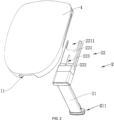
- a support leg 2 provided by an embodiment of the present application is adapted to be mounted on a base 1.
- the support leg 2 includes a support leg body 21, a connector 22 and a stopper 23; the connector 22 is arranged on the support leg body 21, and the connector 22 is slidably connected to the base 1; and the stopper 23 is arranged between the connector 22 and the base 1, and the stopper 23 is configured to limit separation of the connector 22 from the base 1.
- the connector 22 on the support leg body 21 is slidably connected to the base 1, such that the support leg body 21 is mounted on the base 1, and relative sliding between the support leg body 21 and the base 1 is also implemented; and then the stopper 23 is mounted between the connector 22 and the base 1, so as to limit separation of the connector 22 from the base 1, and increase stability of a connection between the connector 22 and the base 1.
- the support leg 2 omits a square tube connection, thereby making the structure simpler and assembly more convenient. It can be seen that the support leg is simple in structure, convenient to assemble, small in dead weight and low in production cost.
- the support leg body 21 is not limited to structures in the accompanying drawings, and can be any structure in the prior art.
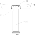
- the support leg body 21 or the connector 22 is provided with a display 3 for displaying a use state of the support leg body 21.
- the connector 22 is connected into a sliding groove 11 on the base 1 in a front-back slidable manner; and the connector 22 is provided with a limiting slot 223 in a front-back direction, one end of the stopper 23 is located in the limiting slot 223, and the other end of the stopper 23 is connected to the base 1.
- a sliding range of the connector 22 can be limited by the stopper 23 and the limiting slot 223, so as to prevent the connector 22 from being separated from the base 1.
- a lower surface of the base 1 is provided with a mounting hole 12 in communication with the sliding groove 11, and the stopper 23 sequentially passes through the mounting hole 12 and the limiting slot 223 to be connected to the base 1. Mounting of the stopper 23 is facilitated through the mounting hole 12.
- the stopper 23 is a screw, and a threaded end of the screw is connected to the base 1 in a threaded manner. Production and assembly are facilitated.
- the connector 22 includes a sliding plate 221, and the sliding plate 221 is slidably connected into the sliding groove 11.
- the structure of the connector 22 is simple, and production is facilitated.
- the connector 22 further includes a reinforcement plate 222, the reinforcement plate 222 is arranged on the sliding plate 221, and the reinforcement plate 222 is slidably connected into the sliding groove 11.
- a compressive strength of the sliding plate 221 namely, the connector 22
- two reinforcement plates 222 are provided, and the two reinforcement plates 222 are formed on a left side and a right side of the sliding plate 221, respectively.
- Production of the connector 22 is facilitated and the production cost is reduced.
- a metal plate is integrally punched to form a blank, and then the blank is integrally punched to form the sliding plate 221 and the reinforcement plate 222.
- a front end of the sliding groove 11 runs through to the outside of the base 1.
- the connector 22 can extend out of the front end of the sliding groove 11 (as shown in FIG. 4 ). That is to say, under the condition that a length of the sliding groove 11 and a length of the connector 22 are fixed, if the connector 22 can extend out of the front end of the sliding groove 11, the sliding range of the connector 22 is wider, thus further widening an adjustment range of the support leg 2. In addition, mounting of the support leg 2 on the base 1 is facilitated.
- the connector 22 extends into, and is connected into the sliding groove 11 in a front-back slidable manner through the front end of the base 1, and then the stopper 23 extends into the sliding groove 11 through the mounting hole 12 on the lower surface of the base 1 and is connected to the base 1 after penetrating the limiting hole, to limit separation of the connector 22 from the front end of the base 1.
- the support leg body 21 and the connector 22 are rotatably connected to each other, and the support leg body 21 can rotate into an accommodation recess 13 on a lower surface of the base 1.
- the support leg body 21 rotates into the accommodation recess 12
- the support leg body 21 is hidden into the base 1, such that a folding function between the support leg body 21 and the base 1 is achieved, an occupied space is reduced, and storage and transportation are facilitated.
- a support portion 211 is generally provided at a lower end of the support leg body 21, so as to increase a contact area between a lower end of the support leg 2 and the ground.
- a child safety seat is provided.
- the child safety seat includes the support leg 2 as stated above.
- the child safety seat in the present application has the same beneficial effects as the support leg 2 above, which will not be repeated herein.
- the support leg and the child safety seat with the support leg are simple in structure, convenient to assemble, small in dead weight and low in production cost.
Landscapes
- Engineering & Computer Science (AREA)
- Health & Medical Sciences (AREA)
- Child & Adolescent Psychology (AREA)
- General Health & Medical Sciences (AREA)
- Aviation & Aerospace Engineering (AREA)
- Transportation (AREA)
- Mechanical Engineering (AREA)
- Seats For Vehicles (AREA)
Abstract
The present application discloses a support leg and a child safety seat. The support leg is adapted to be mounted on a base; the support leg includes a support leg body, a connector and a stopper; the connector is arranged on the support leg body, and the connector is slidably connected to the base; and the stopper is arranged between the connector and the base, and the stopper is configured to limit separation of the connector from the base. The support leg and the child safety seat with the support leg are simple in structure, convenient to assemble, small in dead weight and low in production cost.
Description
- The present application relates to the technical field of child safety seats, in particular to a support leg and a child safety seat.
- At present, with people's increasing attention to child safety in a vehicle, a child safety seat, as an important tool to guarantee the safety, is widely favored by the public. An existing child safety seat generally includes a base and a seat body arranged on the base. In order to prevent the child safety seat from leaning forwards or overturning and falling off in the case of a vehicle collision or emergency brake during traveling, it is increasingly common to equip the child safety seat with support legs under the base for supporting.
- However, the existing support leg is mounted to the base through two square tubes, resulting in a complex structure, a vast number of parts, a large weight, a cumbersome assembly and a high production cost.
- In view of this, how to improve the existing support legs to overcome the above shortcomings is an urgent problem for a person skilled in the art.
- An objective of the present application is to provide a support leg that is simple in structure, convenient to assemble, small in dead weight and low in production cost.
- In order to achieve the above objective, a technical solution used by the present application is as follows: a support leg adapted to be mounted on a base, the support leg comprising a support leg body, a connector and a stopper, wherein the connector is arranged on the support leg body, and the connector is slidably connected to the base; and the stopper is arranged between the connector and the base, and the stopper is configured to limit separation of the connector from the base.
- Preferably, the connector is connected into a sliding groove on the base in a front-back slidable manner; and the connector is provided with a limiting slot in a front-back direction, one end of the stopper is located in the limiting slot, and the other end of the stopper is connected to the base. The advantages are achieved as follows: a sliding range of the connector can be limited by the stopper and the limiting slot, so as to prevent the connector from being separated from the base.
- Preferably, a lower surface of the base is provided with a mounting hole in communication with the sliding groove, and the stopper sequentially passes through the mounting hole and the limiting slot to be connected to the base. The advantages are achieved as follows: mounting of the stopper is facilitated through the mounting hole.
- Preferably, the stopper is a screw, and a threaded end of the screw is connected to the base in a threaded manner. The advantages are achieved as follows: production and assembly are facilitated.
- Preferably, the connector includes a sliding plate, and the sliding plate is slidably connected into the sliding groove. The advantages are achieved as follows: the structure of the connector is simple, and production is facilitated.
- Preferably, the connector further includes a reinforcement plate, the reinforcement plate is arranged on the sliding plate, and the reinforcement plate is slidably connected into the sliding groove. The advantages are achieved as follows: by arranging the reinforcement plate on the sliding plate, a compressive strength of the sliding plate (namely, the connector) is improved.
- Preferably, two reinforcement plates are provided, and the two reinforcement plates are formed on a left side and a right side of the sliding plate, respectively. The advantages are achieved as follows: production of the connector is facilitated and the production cost is reduced. For example, during production, firstly, a metal plate is integrally punched to form a blank, and then the blank is integrally punched to form the sliding plate and the reinforcement plate.
- Preferably, a front end of the sliding groove runs through to the outside of the base. The advantages are achieved as follows: the connector can extend out of the front end of the sliding groove. That is to say, under the condition that a length of the sliding groove and a length of the connector are fixed, if the connector can extend out of the front end of the sliding groove, the sliding range of the connector is wider, thus further widening an adjustment range of the support leg.
- Preferably, the support leg body and the connector are rotatably connected to each other, and the support leg body may rotate into an accommodation recess on a lower surface of the base. The advantages are achieved as follows: when the support leg body rotates into the accommodation recess, the support leg body is hidden into the base, such that a folding function between the support leg body and the base is achieved, an occupied space is reduced, and storage and transportation are facilitated.
- Compared with the prior art, the support leg of the present application has the beneficial effects as follows: during mounting, the connector on the support leg body is slidably connected to the base, such that the support leg body is mounted on the base, and relative sliding between the support leg body and the base is also implemented; and then the stopper is mounted between the connector and the base, so as to limit separation of the connector from the base, and increase stability of a connection between the connector and the base. Compared with an existing assembly structure, the support leg omits a square tube connection, thereby making the structure simpler and assembly more convenient. It can be seen that the support leg is simple in structure, convenient to assemble, small in dead weight and low in production cost.
- The present application further provides a child safety seat, including the support leg as stated above.
- Compared with the prior art, the child safety seat in the present application has the same beneficial effects as the support leg above, which will not be repeated herein.
-
-
FIG. 1 is a perspective view of a support leg and a base according to the present application. -
FIG. 2 is an exploded view of a support leg and a base according to the present application. -
FIG. 3 is a front view of a support leg and a base according to the present application. -
FIGS. 4-5 are diagrams showing a sliding process between a connector and a sliding groove according to the present application. -
FIG. 6 is a top view of a support leg and a base according to the present application. -
FIG. 7 is a sectional view along line A-A inFIG. 6 according to the present application. -
FIG. 8 is a partial enlarged view at portion B inFIG. 7 according to the present application. - In the
figures: 1 . Base; 11. Sliding groove; 12. Mounting hole; 13. Accommodation recess; 2. Support leg; 21. Support leg body; 211. Support portion; 22. Connector; 221. Sliding plate; 2211. Clearance notch; 222. Reinforcement plate; 223. Limiting slot; 23. Stopper; 3. Display. - The present application will be further described below in conjunction with specific embodiments. It should be noted that, on the premise of no conflict, embodiments or technical features described below can be arbitrarily combined to form a new embodiment.
- In the description of the present application, it should be noted that an orientation or positional relationship indicated by an orientation term such as "center", "lateral", "longitudinal", "length", "width", "thickness", "upper", "lower", "front", "rear", "left", "right", "vertical", "horizontal", "top", "bottom", "inner", "outer", "clockwise" or "counterclockwise" is based on an orientation or positional relationship shown in accompanying drawings, is merely used for facilitating the description of the present application and simplifying the description, rather than indicating or implying that a device or element referred to should have a specific orientation or be constructed and operated in a specific orientation, and should not be construed as limiting the scope of protection of the present application.
- It should be noted that a term such as "first" or "second" in the description and the claims of the present application is used to distinguish similar objects, rather than to describe a specific sequence or order.
- The terms such as "include/comprise" and "have" and any variations thereof in the description and the claims of the present application are intended to cover non-exclusive inclusions, for example, processes, methods, systems, products, or devices that include a series of steps or units are not necessarily limited to those explicitly listed steps or units, but can include other steps or units not explicitly listed or inherent to the processes, methods, products, or devices.
- With reference to
FIGS. 1-8 , asupport leg 2 provided by an embodiment of the present application is adapted to be mounted on abase 1. Thesupport leg 2 includes asupport leg body 21, aconnector 22 and astopper 23; theconnector 22 is arranged on thesupport leg body 21, and theconnector 22 is slidably connected to thebase 1; and thestopper 23 is arranged between theconnector 22 and thebase 1, and thestopper 23 is configured to limit separation of theconnector 22 from thebase 1. During mounting, theconnector 22 on thesupport leg body 21 is slidably connected to thebase 1, such that thesupport leg body 21 is mounted on thebase 1, and relative sliding between thesupport leg body 21 and thebase 1 is also implemented; and then thestopper 23 is mounted between theconnector 22 and thebase 1, so as to limit separation of theconnector 22 from thebase 1, and increase stability of a connection between theconnector 22 and thebase 1. Compared with an existing assembly structure, thesupport leg 2 omits a square tube connection, thereby making the structure simpler and assembly more convenient. It can be seen that the support leg is simple in structure, convenient to assemble, small in dead weight and low in production cost. It should be noted that specific structures of thebase 1 and thesupport leg body 21 are not limited to structures in the accompanying drawings, and can be any structure in the prior art. In addition, thesupport leg body 21 or theconnector 22 is provided with adisplay 3 for displaying a use state of thesupport leg body 21. - With reference to
FIGS. 2-8 , in some embodiments of the present application, theconnector 22 is connected into a slidinggroove 11 on thebase 1 in a front-back slidable manner; and theconnector 22 is provided with a limitingslot 223 in a front-back direction, one end of thestopper 23 is located in the limitingslot 223, and the other end of thestopper 23 is connected to thebase 1. A sliding range of theconnector 22 can be limited by thestopper 23 and the limitingslot 223, so as to prevent theconnector 22 from being separated from thebase 1. - With reference to
FIGS. 7-8 , in some embodiments of the present application, a lower surface of thebase 1 is provided with a mountinghole 12 in communication with the slidinggroove 11, and thestopper 23 sequentially passes through the mountinghole 12 and the limitingslot 223 to be connected to thebase 1. Mounting of thestopper 23 is facilitated through the mountinghole 12. - With reference to
FIG. 8 , in some embodiments of the present application, thestopper 23 is a screw, and a threaded end of the screw is connected to thebase 1 in a threaded manner. Production and assembly are facilitated. - With reference to
FIGS. 1-5 , in some embodiments of the present application, theconnector 22 includes a slidingplate 221, and the slidingplate 221 is slidably connected into the slidinggroove 11. The structure of theconnector 22 is simple, and production is facilitated. - With reference to
FIG. 2 , in some embodiments of the present application, theconnector 22 further includes areinforcement plate 222, thereinforcement plate 222 is arranged on the slidingplate 221, and thereinforcement plate 222 is slidably connected into the slidinggroove 11. By arranging thereinforcement plate 222 on the slidingplate 221, a compressive strength of the sliding plate 221 (namely, the connector 22) can be improved. - With reference to
FIG. 2 , in some embodiments of the present application, tworeinforcement plates 222 are provided, and the tworeinforcement plates 222 are formed on a left side and a right side of the slidingplate 221, respectively. Production of theconnector 22 is facilitated and the production cost is reduced. For example, during production, firstly, a metal plate is integrally punched to form a blank, and then the blank is integrally punched to form the slidingplate 221 and thereinforcement plate 222. - With reference to
FIGS. 2-5 , in some embodiments of the present application, a front end of the slidinggroove 11 runs through to the outside of thebase 1. Theconnector 22 can extend out of the front end of the sliding groove 11 (as shown inFIG. 4 ). That is to say, under the condition that a length of the slidinggroove 11 and a length of theconnector 22 are fixed, if theconnector 22 can extend out of the front end of the slidinggroove 11, the sliding range of theconnector 22 is wider, thus further widening an adjustment range of thesupport leg 2. In addition, mounting of thesupport leg 2 on thebase 1 is facilitated. During mounting, theconnector 22 extends into, and is connected into the slidinggroove 11 in a front-back slidable manner through the front end of thebase 1, and then thestopper 23 extends into the slidinggroove 11 through the mountinghole 12 on the lower surface of thebase 1 and is connected to thebase 1 after penetrating the limiting hole, to limit separation of theconnector 22 from the front end of thebase 1. - With reference to
FIGS. 1-2 andFIGS. 6-7 , in some embodiments of the present application, thesupport leg body 21 and theconnector 22 are rotatably connected to each other, and thesupport leg body 21 can rotate into anaccommodation recess 13 on a lower surface of thebase 1. When thesupport leg body 21 rotates into theaccommodation recess 12, thesupport leg body 21 is hidden into thebase 1, such that a folding function between thesupport leg body 21 and thebase 1 is achieved, an occupied space is reduced, and storage and transportation are facilitated. In addition, in order to improve support stability of thesupport leg body 21, asupport portion 211 is generally provided at a lower end of thesupport leg body 21, so as to increase a contact area between a lower end of thesupport leg 2 and the ground. When thesupport leg body 21 rotates and is hidden into theaccommodation recess 13, in order to prevent interference between thesupport portion 211 and theconnector 22, it is necessary to arrange aclearance notch 2211 on the connector 22 (as shown inFIG. 2 ). - With reference to
FIGS. 1-8 , in some embodiments of the present application, a child safety seat is provided. The child safety seat includes thesupport leg 2 as stated above. Compared with the prior art, the child safety seat in the present application has the same beneficial effects as thesupport leg 2 above, which will not be repeated herein. - To sum up, the support leg and the child safety seat with the support leg are simple in structure, convenient to assemble, small in dead weight and low in production cost.
- The basic principles, main features and advantages of the present application are described above. Those skilled in the art shall understand that the present application is not limited to the above embodiments, the above embodiments and the description merely illustrate the principle of the present application, various changes and improvements can be made to the present application without departing from the spirit and scope of the present application, and these changes and improvements shall fall within the scope of protection of the present application. The scope of protection of the present application is defined by the appended claims and their equivalents.
Claims (10)
- A support leg adapted to be mounted on a base, characterized in that the support leg comprises a support leg body, a connector and a stopper; the connector is arranged on the support leg body, and the connector is slidably connected to the base; and the stopper is arranged between the connector and the base, and the stopper is configured to limit separation of the connector from the base.
- The support leg according to claim 1, characterized in that the connector is connected into a sliding groove on the base in a front-back slidable manner; and the connector is provided with a limiting slot in a front-back direction, one end of the stopper is located in the limiting slot, and the other end of the stopper is connected to the base.
- The support leg according to claim 2, characterized in that a lower surface of the base is provided with a mounting hole in communication with the sliding groove, and the stopper sequentially passes through the mounting hole and the limiting slot to be connected to the base.
- The support leg according to claim 3, characterized in that the stopper is a screw, and a threaded end of the screw is connected to the base in a threaded manner.
- The support leg according to claim 2, characterized in that the connector comprises a sliding plate, and the sliding plate is slidably connected into the sliding groove.
- The support leg according to claim 2, characterized in that the connector further comprises a reinforcement plate, the reinforcement plate is arranged on the sliding plate, and the reinforcement plate is slidably connected into the sliding groove.
- The support leg according to claim 6, characterized in that two reinforcement plates are provided, and the two reinforcement plates are formed on a left side and a right side of the sliding plate, respectively.
- The support leg according to claim 2, characterized in that a front end of the sliding groove runs through to the outside of the base.
- The support leg according to claim 1, characterized in that the support leg body and the connector are rotatably connected to each other, and the support leg body can rotate into an accommodation recess on a lower surface of the base.
- A child safety seat, characterized by comprising a support leg according to any one of claims 1-9.
Applications Claiming Priority (1)
| Application Number | Priority Date | Filing Date | Title |
|---|---|---|---|
| CN202221839368.3U CN217753537U (en) | 2022-07-15 | 2022-07-15 | Supporting leg and child safety seat |
Publications (1)
| Publication Number | Publication Date |
|---|---|
| EP4306359A1 true EP4306359A1 (en) | 2024-01-17 |
Family
ID=83873579
Family Applications (1)
| Application Number | Title | Priority Date | Filing Date |
|---|---|---|---|
| EP23184504.1A Pending EP4306359A1 (en) | 2022-07-15 | 2023-07-10 | Support leg and child safety seat |
Country Status (2)
| Country | Link |
|---|---|
| EP (1) | EP4306359A1 (en) |
| CN (1) | CN217753537U (en) |
Citations (2)
| Publication number | Priority date | Publication date | Assignee | Title |
|---|---|---|---|---|
| EP0485121A1 (en) * | 1990-11-09 | 1992-05-13 | Britax-Excelsior Limited | Child safety seat |
| FR2957564A1 (en) * | 2010-03-19 | 2011-09-23 | Dorel France Sa | Safety seat for use by child in vehicle i.e. motor vehicle, has limiting unit limiting angular displacement maintaining soleplate in predetermined angular range with respect to strut or support element |
-
2022
- 2022-07-15 CN CN202221839368.3U patent/CN217753537U/en active Active
-
2023
- 2023-07-10 EP EP23184504.1A patent/EP4306359A1/en active Pending
Patent Citations (2)
| Publication number | Priority date | Publication date | Assignee | Title |
|---|---|---|---|---|
| EP0485121A1 (en) * | 1990-11-09 | 1992-05-13 | Britax-Excelsior Limited | Child safety seat |
| FR2957564A1 (en) * | 2010-03-19 | 2011-09-23 | Dorel France Sa | Safety seat for use by child in vehicle i.e. motor vehicle, has limiting unit limiting angular displacement maintaining soleplate in predetermined angular range with respect to strut or support element |
Also Published As
| Publication number | Publication date |
|---|---|
| CN217753537U (en) | 2022-11-08 |
Similar Documents
| Publication | Publication Date | Title |
|---|---|---|
| US4219175A (en) | Extensible slotted upright | |
| US9247813B2 (en) | Seating furniture with integrated table function | |
| US12240557B2 (en) | Draw-bar box-type quickly folding micro electric vehicle | |
| EP4306359A1 (en) | Support leg and child safety seat | |
| CN218204513U (en) | Highway bridge pile foundation anti-settlement device | |
| CN203510185U (en) | Vehicle wheel hanging rack | |
| CN209177805U (en) | Multifunctional elevator car | |
| CN213383883U (en) | Instrument and vehicle | |
| CN212125202U (en) | Medical foldable shallow | |
| JPS6348772Y2 (en) | ||
| CN211498586U (en) | Portable combined signboard | |
| CN218839275U (en) | Vehicle-mounted red wine cabinet | |
| CN220571833U (en) | Futon folding chair | |
| CN220953064U (en) | Traffic guiding and changing coming vehicle prompting mirror | |
| CN209275945U (en) | A kind of simple turnover plate type construction elevator outfeed platforms | |
| CN205421072U (en) | Special vertical warning sign of vehicle parking | |
| CN215710889U (en) | Elevator overhauls isolated column | |
| CN205063792U (en) | Multistep ladder | |
| CN223482399U (en) | Protective fence for hydraulic engineering construction | |
| CN212125056U (en) | Light environment-friendly driver enclosure for passenger car | |
| CN110397877A (en) | One kind is anti-to topple over street lamp | |
| CN217649366U (en) | Self-unloading lifting pedal device for airport maintenance vehicle | |
| CN218942687U (en) | Adjustable back cushion structure | |
| CN221609718U (en) | Secondary security check fence | |
| JPH0412824Y2 (en) |
Legal Events
| Date | Code | Title | Description |
|---|---|---|---|
| PUAI | Public reference made under article 153(3) epc to a published international application that has entered the european phase |
Free format text: ORIGINAL CODE: 0009012 |
|
| STAA | Information on the status of an ep patent application or granted ep patent |
Free format text: STATUS: REQUEST FOR EXAMINATION WAS MADE |
|
| STAA | Information on the status of an ep patent application or granted ep patent |
Free format text: STATUS: EXAMINATION IS IN PROGRESS |
|
| 17P | Request for examination filed |
Effective date: 20230710 |
|
| AK | Designated contracting states |
Kind code of ref document: A1 Designated state(s): AL AT BE BG CH CY CZ DE DK EE ES FI FR GB GR HR HU IE IS IT LI LT LU LV MC ME MK MT NL NO PL PT RO RS SE SI SK SM TR |
|
| 17Q | First examination report despatched |
Effective date: 20240105 |