EP4306352A1 - Motor vehicle with wheel hub motors - Google Patents
Motor vehicle with wheel hub motors Download PDFInfo
- Publication number
- EP4306352A1 EP4306352A1 EP23179934.7A EP23179934A EP4306352A1 EP 4306352 A1 EP4306352 A1 EP 4306352A1 EP 23179934 A EP23179934 A EP 23179934A EP 4306352 A1 EP4306352 A1 EP 4306352A1
- Authority
- EP
- European Patent Office
- Prior art keywords
- torque
- available
- engine brake
- frmot
- electric machines
- Prior art date
- Legal status (The legal status is an assumption and is not a legal conclusion. Google has not performed a legal analysis and makes no representation as to the accuracy of the status listed.)
- Pending
Links
- 230000001172 regenerating effect Effects 0.000 claims abstract description 143
- 238000004088 simulation Methods 0.000 claims abstract description 86
- 238000000034 method Methods 0.000 claims abstract description 47
- 230000008569 process Effects 0.000 claims abstract description 42
- 230000002441 reversible effect Effects 0.000 claims abstract description 7
- 230000004913 activation Effects 0.000 claims description 12
- 230000001133 acceleration Effects 0.000 claims description 3
- 230000000694 effects Effects 0.000 claims description 3
- 238000006243 chemical reaction Methods 0.000 description 10
- 230000009467 reduction Effects 0.000 description 2
- 238000004148 unit process Methods 0.000 description 2
- 230000001464 adherent effect Effects 0.000 description 1
- 239000010426 asphalt Substances 0.000 description 1
- 230000006399 behavior Effects 0.000 description 1
- 230000008859 change Effects 0.000 description 1
- 238000010586 diagram Methods 0.000 description 1
- 230000014509 gene expression Effects 0.000 description 1
- 230000017525 heat dissipation Effects 0.000 description 1
- 238000012423 maintenance Methods 0.000 description 1
- 230000008929 regeneration Effects 0.000 description 1
- 238000011069 regeneration method Methods 0.000 description 1
- 230000035807 sensation Effects 0.000 description 1
Images




Classifications
-
- B—PERFORMING OPERATIONS; TRANSPORTING
- B60—VEHICLES IN GENERAL
- B60L—PROPULSION OF ELECTRICALLY-PROPELLED VEHICLES; SUPPLYING ELECTRIC POWER FOR AUXILIARY EQUIPMENT OF ELECTRICALLY-PROPELLED VEHICLES; ELECTRODYNAMIC BRAKE SYSTEMS FOR VEHICLES IN GENERAL; MAGNETIC SUSPENSION OR LEVITATION FOR VEHICLES; MONITORING OPERATING VARIABLES OF ELECTRICALLY-PROPELLED VEHICLES; ELECTRIC SAFETY DEVICES FOR ELECTRICALLY-PROPELLED VEHICLES
- B60L7/00—Electrodynamic brake systems for vehicles in general
- B60L7/10—Dynamic electric regenerative braking
- B60L7/18—Controlling the braking effect
-
- B—PERFORMING OPERATIONS; TRANSPORTING
- B60—VEHICLES IN GENERAL
- B60L—PROPULSION OF ELECTRICALLY-PROPELLED VEHICLES; SUPPLYING ELECTRIC POWER FOR AUXILIARY EQUIPMENT OF ELECTRICALLY-PROPELLED VEHICLES; ELECTRODYNAMIC BRAKE SYSTEMS FOR VEHICLES IN GENERAL; MAGNETIC SUSPENSION OR LEVITATION FOR VEHICLES; MONITORING OPERATING VARIABLES OF ELECTRICALLY-PROPELLED VEHICLES; ELECTRIC SAFETY DEVICES FOR ELECTRICALLY-PROPELLED VEHICLES
- B60L15/00—Methods, circuits, or devices for controlling the traction-motor speed of electrically-propelled vehicles
- B60L15/32—Control or regulation of multiple-unit electrically-propelled vehicles
-
- B—PERFORMING OPERATIONS; TRANSPORTING
- B60—VEHICLES IN GENERAL
- B60K—ARRANGEMENT OR MOUNTING OF PROPULSION UNITS OR OF TRANSMISSIONS IN VEHICLES; ARRANGEMENT OR MOUNTING OF PLURAL DIVERSE PRIME-MOVERS IN VEHICLES; AUXILIARY DRIVES FOR VEHICLES; INSTRUMENTATION OR DASHBOARDS FOR VEHICLES; ARRANGEMENTS IN CONNECTION WITH COOLING, AIR INTAKE, GAS EXHAUST OR FUEL SUPPLY OF PROPULSION UNITS IN VEHICLES
- B60K7/00—Disposition of motor in, or adjacent to, traction wheel
- B60K7/0007—Disposition of motor in, or adjacent to, traction wheel the motor being electric
-
- B—PERFORMING OPERATIONS; TRANSPORTING
- B60—VEHICLES IN GENERAL
- B60L—PROPULSION OF ELECTRICALLY-PROPELLED VEHICLES; SUPPLYING ELECTRIC POWER FOR AUXILIARY EQUIPMENT OF ELECTRICALLY-PROPELLED VEHICLES; ELECTRODYNAMIC BRAKE SYSTEMS FOR VEHICLES IN GENERAL; MAGNETIC SUSPENSION OR LEVITATION FOR VEHICLES; MONITORING OPERATING VARIABLES OF ELECTRICALLY-PROPELLED VEHICLES; ELECTRIC SAFETY DEVICES FOR ELECTRICALLY-PROPELLED VEHICLES
- B60L7/00—Electrodynamic brake systems for vehicles in general
- B60L7/10—Dynamic electric regenerative braking
-
- B—PERFORMING OPERATIONS; TRANSPORTING
- B60—VEHICLES IN GENERAL
- B60L—PROPULSION OF ELECTRICALLY-PROPELLED VEHICLES; SUPPLYING ELECTRIC POWER FOR AUXILIARY EQUIPMENT OF ELECTRICALLY-PROPELLED VEHICLES; ELECTRODYNAMIC BRAKE SYSTEMS FOR VEHICLES IN GENERAL; MAGNETIC SUSPENSION OR LEVITATION FOR VEHICLES; MONITORING OPERATING VARIABLES OF ELECTRICALLY-PROPELLED VEHICLES; ELECTRIC SAFETY DEVICES FOR ELECTRICALLY-PROPELLED VEHICLES
- B60L7/00—Electrodynamic brake systems for vehicles in general
- B60L7/24—Electrodynamic brake systems for vehicles in general with additional mechanical or electromagnetic braking
- B60L7/26—Controlling the braking effect
-
- B—PERFORMING OPERATIONS; TRANSPORTING
- B60—VEHICLES IN GENERAL
- B60L—PROPULSION OF ELECTRICALLY-PROPELLED VEHICLES; SUPPLYING ELECTRIC POWER FOR AUXILIARY EQUIPMENT OF ELECTRICALLY-PROPELLED VEHICLES; ELECTRODYNAMIC BRAKE SYSTEMS FOR VEHICLES IN GENERAL; MAGNETIC SUSPENSION OR LEVITATION FOR VEHICLES; MONITORING OPERATING VARIABLES OF ELECTRICALLY-PROPELLED VEHICLES; ELECTRIC SAFETY DEVICES FOR ELECTRICALLY-PROPELLED VEHICLES
- B60L2220/00—Electrical machine types; Structures or applications thereof
- B60L2220/40—Electrical machine applications
- B60L2220/42—Electrical machine applications with use of more than one motor
-
- B—PERFORMING OPERATIONS; TRANSPORTING
- B60—VEHICLES IN GENERAL
- B60L—PROPULSION OF ELECTRICALLY-PROPELLED VEHICLES; SUPPLYING ELECTRIC POWER FOR AUXILIARY EQUIPMENT OF ELECTRICALLY-PROPELLED VEHICLES; ELECTRODYNAMIC BRAKE SYSTEMS FOR VEHICLES IN GENERAL; MAGNETIC SUSPENSION OR LEVITATION FOR VEHICLES; MONITORING OPERATING VARIABLES OF ELECTRICALLY-PROPELLED VEHICLES; ELECTRIC SAFETY DEVICES FOR ELECTRICALLY-PROPELLED VEHICLES
- B60L2220/00—Electrical machine types; Structures or applications thereof
- B60L2220/40—Electrical machine applications
- B60L2220/44—Wheel Hub motors, i.e. integrated in the wheel hub
-
- B—PERFORMING OPERATIONS; TRANSPORTING
- B60—VEHICLES IN GENERAL
- B60L—PROPULSION OF ELECTRICALLY-PROPELLED VEHICLES; SUPPLYING ELECTRIC POWER FOR AUXILIARY EQUIPMENT OF ELECTRICALLY-PROPELLED VEHICLES; ELECTRODYNAMIC BRAKE SYSTEMS FOR VEHICLES IN GENERAL; MAGNETIC SUSPENSION OR LEVITATION FOR VEHICLES; MONITORING OPERATING VARIABLES OF ELECTRICALLY-PROPELLED VEHICLES; ELECTRIC SAFETY DEVICES FOR ELECTRICALLY-PROPELLED VEHICLES
- B60L2220/00—Electrical machine types; Structures or applications thereof
- B60L2220/40—Electrical machine applications
- B60L2220/46—Wheel motors, i.e. motor connected to only one wheel
-
- B—PERFORMING OPERATIONS; TRANSPORTING
- B60—VEHICLES IN GENERAL
- B60L—PROPULSION OF ELECTRICALLY-PROPELLED VEHICLES; SUPPLYING ELECTRIC POWER FOR AUXILIARY EQUIPMENT OF ELECTRICALLY-PROPELLED VEHICLES; ELECTRODYNAMIC BRAKE SYSTEMS FOR VEHICLES IN GENERAL; MAGNETIC SUSPENSION OR LEVITATION FOR VEHICLES; MONITORING OPERATING VARIABLES OF ELECTRICALLY-PROPELLED VEHICLES; ELECTRIC SAFETY DEVICES FOR ELECTRICALLY-PROPELLED VEHICLES
- B60L2240/00—Control parameters of input or output; Target parameters
- B60L2240/40—Drive Train control parameters
- B60L2240/42—Drive Train control parameters related to electric machines
-
- B—PERFORMING OPERATIONS; TRANSPORTING
- B60—VEHICLES IN GENERAL
- B60L—PROPULSION OF ELECTRICALLY-PROPELLED VEHICLES; SUPPLYING ELECTRIC POWER FOR AUXILIARY EQUIPMENT OF ELECTRICALLY-PROPELLED VEHICLES; ELECTRODYNAMIC BRAKE SYSTEMS FOR VEHICLES IN GENERAL; MAGNETIC SUSPENSION OR LEVITATION FOR VEHICLES; MONITORING OPERATING VARIABLES OF ELECTRICALLY-PROPELLED VEHICLES; ELECTRIC SAFETY DEVICES FOR ELECTRICALLY-PROPELLED VEHICLES
- B60L2240/00—Control parameters of input or output; Target parameters
- B60L2240/40—Drive Train control parameters
- B60L2240/42—Drive Train control parameters related to electric machines
- B60L2240/421—Speed
-
- B—PERFORMING OPERATIONS; TRANSPORTING
- B60—VEHICLES IN GENERAL
- B60L—PROPULSION OF ELECTRICALLY-PROPELLED VEHICLES; SUPPLYING ELECTRIC POWER FOR AUXILIARY EQUIPMENT OF ELECTRICALLY-PROPELLED VEHICLES; ELECTRODYNAMIC BRAKE SYSTEMS FOR VEHICLES IN GENERAL; MAGNETIC SUSPENSION OR LEVITATION FOR VEHICLES; MONITORING OPERATING VARIABLES OF ELECTRICALLY-PROPELLED VEHICLES; ELECTRIC SAFETY DEVICES FOR ELECTRICALLY-PROPELLED VEHICLES
- B60L2240/00—Control parameters of input or output; Target parameters
- B60L2240/40—Drive Train control parameters
- B60L2240/42—Drive Train control parameters related to electric machines
- B60L2240/423—Torque
-
- B—PERFORMING OPERATIONS; TRANSPORTING
- B60—VEHICLES IN GENERAL
- B60L—PROPULSION OF ELECTRICALLY-PROPELLED VEHICLES; SUPPLYING ELECTRIC POWER FOR AUXILIARY EQUIPMENT OF ELECTRICALLY-PROPELLED VEHICLES; ELECTRODYNAMIC BRAKE SYSTEMS FOR VEHICLES IN GENERAL; MAGNETIC SUSPENSION OR LEVITATION FOR VEHICLES; MONITORING OPERATING VARIABLES OF ELECTRICALLY-PROPELLED VEHICLES; ELECTRIC SAFETY DEVICES FOR ELECTRICALLY-PROPELLED VEHICLES
- B60L2240/00—Control parameters of input or output; Target parameters
- B60L2240/40—Drive Train control parameters
- B60L2240/54—Drive Train control parameters related to batteries
- B60L2240/547—Voltage
-
- Y—GENERAL TAGGING OF NEW TECHNOLOGICAL DEVELOPMENTS; GENERAL TAGGING OF CROSS-SECTIONAL TECHNOLOGIES SPANNING OVER SEVERAL SECTIONS OF THE IPC; TECHNICAL SUBJECTS COVERED BY FORMER USPC CROSS-REFERENCE ART COLLECTIONS [XRACs] AND DIGESTS
- Y02—TECHNOLOGIES OR APPLICATIONS FOR MITIGATION OR ADAPTATION AGAINST CLIMATE CHANGE
- Y02T—CLIMATE CHANGE MITIGATION TECHNOLOGIES RELATED TO TRANSPORTATION
- Y02T10/00—Road transport of goods or passengers
- Y02T10/60—Other road transportation technologies with climate change mitigation effect
- Y02T10/62—Hybrid vehicles
Definitions
- the invention relates to a motor vehicle and to a method to control a plurality of electric machines of the motor vehicle.
- the invention relates to a motor vehicle with a drive system provided with at least two electric motors exclusively powered by an electric battery and lacking heat engines.
- BEV Battery Electric Vehicle
- Motor vehicles which comprise:
- Known motor vehicles further comprise:
- the electric machines are, in a known manner, reversible, which means that they can operate both as electric motors and as electric generators.
- the electric machines When the accelerator pedal is operated, the electric machines operate as electric motors, namely they are electrically powered by the battery and generate respective torques acting upon the wheels.
- the electric machines When they operate as electric generators, the electric machines convert a share of the kinetic energy of the motor vehicle into an electric current that becomes available to the battery.
- Said electric current charges the high-voltage electric battery or powers high-voltage auxiliary loads, carrying out what is commonly known in the industry as "regenerative braking”.
- the brake control unit When the brake pedal is operated, the brake control unit establishes a braking torque value to be exerted upon the wheels.
- the brake control unit operates the braking system so as to exert a first share of the braking torque and the control unit operates the electric machines as electric generators, so as to generate a remaining second share of the braking torque.
- the control unit processes the entire braking torque value.
- the first share is zero and the second share corresponds to the entire braking torque.
- Said braking torque value is not necessary to meet a driver's request, but simulates the braking torque normally generated for the wheels of a motor vehicle provided with a heat engine following the release of the accelerator pedal and the drag of the heat engine.
- said braking torque is generated with the aim of providing the driver with a driving sensation that is similar to the one that he/she would have with a traditional motor vehicle provided with a heat engine.
- the electrical power that can still be stored in the battery constitutes a limit exceeding the value of the braking torque generated by means of the electric machines operated as electric generators.
- the braking system for safety reasons, is sized so that it can deliver all the braking torque normally requested by the driver during the normal operation of the motor vehicle.
- the braking system is sized as if there were no possibility or a substantially very small possibility of "regenerative braking".
- the increase in the second share of braking torque determines a corresponding decrease in the first share of braking torque requested to the traditional braking system, given the same request of the driver, thus allowing for a decrease in the maximum quantity of heat energy to be dissipated by the braking system and in the wear phenomena affecting the braking system itself, with evident advantages in terms of reduction of spaces, weights and maintenance costs.
- the second share of braking torque has to be increased respecting given parameters of distribution of said braking torque between a front axle formed by the front wheels and a rear axle formed by the rear wheels and between the two left/right wheels of the same front/rear axle.
- the object of the invention is to provide a motor vehicle, which is capable of fulfilling at least one of the needs discussed above.
- the invention relates to a method to control a plurality of electric machines of the motor vehicle as set forth in claim 11.
- number 1 indicates a motor vehicle, in particular an electric motor vehicle, which, therefore, lacks heat engines.
- the motor vehicle 1 comprises:
- the motor vehicle 1 further comprises:
- the motor vehicle 1 further comprises:
- the brake control unit IPB causes the braking system 10 to generate the hydraulic braking torque following the activation of the pedal 7 or when the pedal 7 is deactivated in order to ensure a certain level of stability of the vehicle 1.
- the braking system 10 generates the hydraulic braking torque through heat dissipation via friction by means of pads and respective discs carried by the wheels 2, 3, 4, 5.
- the electric machines RL, RR, FL, FR are reversible and can be operated as:
- the electric machines RL, RR, FL, FR When they are used as electric generators, the electric machines RL, RR, FL, FR generate the electric braking torque acting upon the respective wheels 4, 5, 2, 3.
- control unit VCU is programmed to have the electric machines RL, RR, FL, FR operated as electric generators actuate:
- the control unit VCU is advantageously programmed, in case of release of the pedal 8, to:
- control unit VCU processes the values of the first, second, third and fourth torque to be implemented by means of the respective electric machines RL, RR, FL, FR autonomously from the brake control unit IPB, in case of regenerative engine brake simulation.
- control unit VCU is programmed to process the values of the fifth, sixth, seventh and eighth torque to be regenerated for the regenerative braking by means of the respective electric machines RL, RR, FL, FR also based on the electrical power regenerated by the electric machines RL, RR, FL, FR for the regenerative engine brake simulation.
- the control unit VCU is programmed to receive from the brake control unit IPB:
- Front-Rear Engine Brake Split and left-right Engine Brake Split depend, in a non-limiting manner, on the following sub-parameters:
- Front-Rear Braking Split, left-right F Braking Split and left-right R Braking Split depend, in a non-limiting manner, on the following sub-parameters:
- Front-Rear Braking Split and left-right Braking Split are updated in a dynamic manner over time, as the operating conditions on which they depend change.
- the control unit VCU further has, in its memory ( Figure 6 ), a table associating the value of a parameter Overbraking_TgtTq corresponding to a target braking torque value for the regenerative engine brake simulation with a value of the forward speed of the motor vehicle 1.
- control unit VCU receives, in real time, the value of the electrical power currently regenerated by the electric machines RL, RR, FL, FR.
- the brake control unit IPB has, in its memory, the parameters left-right Front RegBr Split and left-right Rear RegBr Split, which dynamically depend, over time, on the operating parameters of the motor vehicle 1.
- control unit VCU receives from the pedal 8 a signal corresponding to the fact that the pedal 8 was deactivated.
- the control unit VCU further receives, as an input, the value Lim Recharge HVB corresponding to the maximum value of the electrical power that can be stored in the battery 6 (step 1).
- the control unit VCU is programmed (step 2) to process the value Lim Recharge VCU corresponding to the maximum electrical power that can be regenerated according to formula (1): Lim Recharge HVB + Aux ⁇ buffer wherein:
- the control unit VCU is programmed to:
- Said second parameters correspond, in the specific case shown herein, to the angular speed of the electric machines RL, RR and to the respective efficiencies of conversion of the first and second electrical power communicated by the control unit VCU into mechanical power available to the wheels 4, 5.
- the values of the first and second torque available for the regenerative engine brake simulation are processed by the respective electric machines RR, RL for they comprise respective angular speed sensors and have, in their memory, respective values of the conversion efficiencies.
- the control unit is further programmed to process (step 5) the value of the first and second torque regenerated for the regenerative engine brake simulation by the electric machines RL, RR according to formulas (4), (5) :
- First torque regenerated for the regenerative engine brake simulation by the electric machine RL MIN (Overbraking_TgtTq * Front-Rear EnBr Split * (1-Right-left Rear EnBr Split); First torque Available for the regenerative engine brake simulation for the electric machine RL (4).
- Second torque regenerated for the regenerative engine brake simulation by the electric machine RR MIN (Overbraking_TgtTq * Front-Rear EnBr Split * Right-left Rear EnBr Split); First torque Available for the regenerative engine brake simulation for the electric machine RL (5).
- control unit VCU is programmed to process, as first and second torque to be regenerated by means of the electric machines RL, RR, the first and second torque available for the electric machines RL, RR, in case they are lower than the target values stored in the control unit VCU for the current value of the forward speed of the motor vehicle 1 and are split among the wheels 2, 3, 4, 5 based on the coefficients Front-Rear EnBr Split * (1-Right-left Rear EnBr Split).
- the control unit VCU is further programmed to communicate the aforesaid values of the first and second torque regenerated for the regenerative engine brake simulation by the electric machines RL, RR to the electric machines RL, RR themselves.
- the electric machines RL, RR are programmed (step 6) to calculate and communicate to the control unit VCU the values of the first and second electrical power regenerated for the regenerative engine brake simulation based on the aforesaid values of the torque regenerated for the regenerative engine brake simulation by the electric machines RL, RR, on the angular speeds of the electric machines RL, RR and on the conversion efficiencies of the electric machines RL, RR.
- the control unit VCU is further programmed to process the values of the third and fourth power available for the regenerative engine brake simulation for the electric machines FR, FL based on the sum of the values of the first and second electrical power regenerated for the regenerative engine brake simulation for the electric machines RR, RL calculated in step 6 (step 7).
- control unit VCU is programmed to process the values of the third and fourth power available for the regenerative engine brake simulation for the electric machines FR, FL by means of the following formulas:
- the control unit VCU is further programmed to:
- the electric machines FL, FR are programmed (step 10) to calculate and communicate to the control unit VCU the values of the third and fourth electrical power regenerated for the regenerative engine brake simulation based on the aforesaid values of the third and fourth torque regenerated for the regenerative engine brake simulation by the electric machines FR, FL and on the second parameters, in the specific case shown herein the angular speeds and the conversion efficiencies of the electric machines FR, FL.
- the aforesaid first, second, third and fourth torque regenerated for the regenerative engine brake simulation by the electric machine RL, RR, FL, FR correspond to the first, second, third and fourth torque to be implemented for the regenerative engine brake simulation, respectively.
- steps (7)-(10) are carried out simultaneously with steps (3)-(6).
- the control unit VCU is further programmed to process the values of the fifth, sixth, seventh and eighth power available for the regenerative braking for the electric machines RL, RR, FL, FR.
- control unit VCU is programmed to process the values of the fifth and of the sixth power available for the regenerative braking for the electric machines FL, FR based on the following formulas (step 11):
- Sixth power available for the Regenerative Braking for the electric machine FR Lim Recharge VCU ⁇ Sum of the first , second , third and fourth power regenerated for the regenerative engine brake simulation * right ⁇ left Braking Split ) * front / rear Braking Split;
- Fifth power available for the Regenerative Braking for the electric machine FL Lim Recharge VCU ⁇ Sum of the first , second , third and fourth power regenerated for the regenerative engine brake simulation * 1 ⁇ right ⁇ left F Braking Split * front / rear Braking Split
- the control unit VCU is further programmed to:
- the control unit VCU is programmed to process a sum of the fifth and of the sixth torque available for the regenerative braking for the electric machines FL, FR.
- the control unit VCU is programmed to calculate and communicate to the brake control unit IPB the maximum value of the torque available for the regenerative braking for the front axle 11 (step 13).
- the control unit VCU is further programmed to:
- the electric machines RL, RR further communicate the value of the maximum torque available for the regenerative braking for the rear axle 12 (step 15bis).
- the control unit VCU is programmed to process a sum of the seventh and eighth torque available for the regenerative braking for the electric machines RL, RR.
- the control unit VCU is further programmed to calculate and communicate to the brake control unit IPB the maximum value of the torque available for the regenerative braking for the rear axle 12 (step 16).
- Maximum value of the torque available for the Regenerative Braking for the rear axle 12 MIN Torque available for the regenerative braking on the rear axle 12 ;
- the brake control unit IBP is programmed to process:
- the control unit VCU is programmed to cause:
- the sum of the first, second, third, fourth, fifth, sixth, seventh, eighth electric torque corresponds to the electric braking torque.
- the brake control unit IPB is programmed to cause the braking system 10 to generate a braking torque corresponding to the difference between the braking torque requested by the driver by means of the pedal 7 and the sum of the fifth, sixth, seventh and eight torque regenerated for the regenerative braking requested by the brake control unit IPB.
- the brake control unit IPB makes up for the amount of braking torque requested by the driver which cannot be obtained through regenerative braking.
- the operation of the motor vehicle 1 is described hereinafter starting from an operating condition in which the driver activates the pedal 8 in order to request desired torque values to be delivered to wheels 2, 3, 4, 5.
- the battery 6 electrically powers the electric machines RL, RR, FL, FR, which generate respective torques acting upon the corresponding wheels 4, 5, 2, 3.
- control unit VCU has processed the values of the first, second, third and fourth torque regenerated for the engine brake simulation of the respective electric machines RL, RR, FL, FR.
- control unit VCU carries out steps 11-17) described above and the brake control unit IPB communicates to the control unit VCU values of the fifth, sixth, seventh and eighth torque regenerated for the regenerative braking for the respective electric machines RL, RR, FL, FR.
- control unit VCU causes:
- the sum of the first, second, third, fourth, fifth, sixth, seventh, eighth electric torque corresponds to the electric braking torque.
- the brake control unit IPB causes the braking system 10 to generate a braking torque corresponding to the difference between the braking torque requested by the driver by means of the pedal 7 and the sum of the fifth, sixth, seventh and eight torque regenerated for the regenerative braking requested by the brake control unit IPB.
- control unit VCU is programmed, in case of release of the pedal 8, to:
- the first, second, third and fourth torque to be implemented RL Torque regenerated via engine brake; RR Torque regenerated via engine brake; FL Torque regenerated via engine brake; FR Torque regenerated via engine brake are processed based on the actual amount of electrical power Lim Recharge VCU still storable in the battery 6, based on desired dynamic features for the split of the power to the wheels 4, 5, 2, 3 represented by the coefficients Right-left Rear EnBr Split, Right-left Rear EnBr Split and based on the conversion efficiency and the number of revolutions of the electric machines RL, RR, FL, FR.
- the quantity of electrical power regenerated in the battery 6 and, consequently, the values of the first, second, third and fourth implemented electrical torque can be maximized, respecting the limits of the battery 6 and of the electric machines RL, RR, FL, FR, in case of the regenerative simulation of the engine brake effect following the release of the pedal 8.
- the brake control unit processes the fifth, sixth, seventh, eighth torque to be implemented for the electric machines RL, RR, FL, FR based on the actual power Lim Recharge VCU still storable in the battery 6, based on the desired dynamic features for the split of the power to the wheels 4, 5, 2, 3 represented by front/rear Braking Split, right-left F Braking Split; right-left R Braking Split and on the power currently implemented for the regenerative engine brake simulation.
- said values of the fifth, sixth, seventh, eighth torque implemented for the electric machines RL, RR, FL, FR in case of activation of the brake pedal 7 are also processed respecting the electrical power still storable in the battery 6 and the features of the electric machines RL, RR, FL, FR as well as the desired dynamic features of the motor vehicle 1, in case of activation of the pedal 7.
- control unit VCU is programmed to process the third and fourth value of the electrical power available for the regenerative engine brake simulation Power available to EnBr for EM FL; Power available to EnBr for EM FR for the electric machines FL, FR acting upon the axle 11, based on the electrical power regenerated on the axle 12 for the regenerative engine brake simulation.
- the control unit VCU processes the first and second value of the electrical power available for the regenerative engine brake simulation Power available to EnBr for EM RL; Power available to EnBr for EM RR for the electric machines FL, FR operating on the axle 12 with priority relative to the aforesaid third and fourth value of the electrical power available for the regenerative engine brake simulation Power available to EnBr for EM FL; Power available to EnBr for EM FR for the electric machines FL, FR operating on the axle 11.
- control unit VCU is programmed to process the fifth and sixth value of the electrical power available for the regenerative braking Power available to RegBr for EM RL; Power available to RegBr for EM RR for the electric machines RL, RR acting upon the axle 12, based on the power currently implemented on the axle 11.
- the control unit VCU processes the seventh and eighth value of the electrical power available for the regenerative braking Power available to RegBr for EM FL; Power available to RegBr for EM FR for the electric machines FL, FR operating on the axis 11 with priority relative to the aforesaid fifth and sixth value of the electrical power available for the regenerative braking Power available to RegBr for EM RL; Power available to RegBr for EM RR for the electric machines RL, RR operating on the axis 12.
- the aforesaid first, second, third, fourth, fifth, sixth, seventh and eighth power can be split among the wheels 4, 5, 2, 3 in a way that is more adherent to the normal behaviour of motor vehicles in case of release of the pedal 8 or activation of the pedal 7.
Landscapes
- Engineering & Computer Science (AREA)
- Transportation (AREA)
- Mechanical Engineering (AREA)
- Power Engineering (AREA)
- Physics & Mathematics (AREA)
- Electromagnetism (AREA)
- Chemical & Material Sciences (AREA)
- Combustion & Propulsion (AREA)
- Electric Propulsion And Braking For Vehicles (AREA)
- Regulating Braking Force (AREA)
Abstract
Description
- This patent application claims priority from
Italian patent application no. 102022000012946 filed on June 20, 2022 - The invention relates to a motor vehicle and to a method to control a plurality of electric machines of the motor vehicle.
- More in detail, the invention relates to a motor vehicle with a drive system provided with at least two electric motors exclusively powered by an electric battery and lacking heat engines.
- Said drive system is commonly known as Battery Electric Vehicle (BEV).
- Motor vehicles are known, which comprise:
- a plurality of electric machines associated with respective wheels;
- a high-voltage battery electrically connected to the electric machines;
- a brake pedal, which can be operated by a driver in order to generate a braking torque acting upon the wheels; and
- an accelerator pedal, which can be operated by the driver in order to increase a torque acting upon the wheels.
- Known motor vehicles further comprise:
- a control unit, which is operatively connected to the accelerator pedal and to the electric machines;
- a hydraulic braking system, which can be operated in order to generate hydraulic braking torques acting upon the wheels and is operatively connected to the brake pedal; and
- a brake control unit of the "brake by wire" kind, which is designed to control the braking system and is operatively connected to the control unit and the braking system.
- The electric machines are, in a known manner, reversible, which means that they can operate both as electric motors and as electric generators.
- When the accelerator pedal is operated, the electric machines operate as electric motors, namely they are electrically powered by the battery and generate respective torques acting upon the wheels.
- When they operate as electric generators, the electric machines convert a share of the kinetic energy of the motor vehicle into an electric current that becomes available to the battery.
- Said electric current charges the high-voltage electric battery or powers high-voltage auxiliary loads, carrying out what is commonly known in the industry as "regenerative braking".
- When the brake pedal is operated, the brake control unit establishes a braking torque value to be exerted upon the wheels.
- In particular, the brake control unit operates the braking system so as to exert a first share of the braking torque and the control unit operates the electric machines as electric generators, so as to generate a remaining second share of the braking torque.
- When the accelerator pedal is released, the control unit processes the entire braking torque value. In other words, the first share is zero and the second share corresponds to the entire braking torque.
- Said braking torque value is not necessary to meet a driver's request, but simulates the braking torque normally generated for the wheels of a motor vehicle provided with a heat engine following the release of the accelerator pedal and the drag of the heat engine.
- In other words, said braking torque is generated with the aim of providing the driver with a driving sensation that is similar to the one that he/she would have with a traditional motor vehicle provided with a heat engine.
- The electrical power that can still be stored in the battery constitutes a limit exceeding the value of the braking torque generated by means of the electric machines operated as electric generators.
- For this reason, in known solutions, the braking system, for safety reasons, is sized so that it can deliver all the braking torque normally requested by the driver during the normal operation of the motor vehicle.
- In order words, the braking system is sized as if there were no possibility or a substantially very small possibility of "regenerative braking".
- In the industry there is a strong need to increase, as much as possible, the second share of braking torque generated by means of the electric machines in each operating condition of the motor vehicle.
- This, first of all, with the purpose of increasing, as much as possible, the charging of the battery obtained through "regenerative braking" and the consequent range of the motor vehicle with no need to charge the battery with power sources that are external to the motor vehicle, such as for example charging outlets.
- Secondly, the increase in the second share of braking torque determines a corresponding decrease in the first share of braking torque requested to the traditional braking system, given the same request of the driver, thus allowing for a decrease in the maximum quantity of heat energy to be dissipated by the braking system and in the wear phenomena affecting the braking system itself, with evident advantages in terms of reduction of spaces, weights and maintenance costs.
- Furthermore, the second share of braking torque has to be increased respecting given parameters of distribution of said braking torque between a front axle formed by the front wheels and a rear axle formed by the rear wheels and between the two left/right wheels of the same front/rear axle.
- Finally, there is the need to respect the regeneration limits of the high-voltage battery and of the single electric machines, even in the most critical dynamic manoeuvres.
- The object of the invention is to provide a motor vehicle, which is capable of fulfilling at least one of the needs discussed above.
- The aforesaid object is reached by the invention, as it relates to a motor vehicle as defined in
claim 1. - Furthermore, the invention relates to a method to control a plurality of electric machines of the motor vehicle as set forth in
claim 11. - The invention will be best understood upon perusal of the following detailed description of a preferred embodiment, which is provided by way of non-limiting example, with reference to the accompanying drawings, wherein:
-
figure 1 is a perspective view of a motor vehicle according to the invention; -
figure 2 is a top view of the motor vehicle offigure 1 with parts removed for greater clarity; -
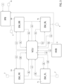
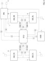
figures 3 and4 schematically show further components of the motor vehicle offigures 1 and2 and the respective operating steps; -
figure 5 explains the numbers used for the operating steps infigure 4 ; and -
figure 6 shows an adjustment diagram used in the operating steps offigures 3 and4 . - With reference to the accompanying Figures,
number 1 indicates a motor vehicle, in particular an electric motor vehicle, which, therefore, lacks heat engines. - Hereinafter, expressions such as "at the top", "at the bottom", "at the front", "at the back" and others similar to them are used with reference to normal forward moving conditions of the
motor vehicle 1. - Furthermore, it is possible to define:
- a longitudinal axis X integral to the
motor vehicle 1, which, in use, is horizontal and parallel to a normal forward moving direction of themotor vehicle 1; - a transverse axis X integral to the
vehicle 1, which, in use, is horizontal and orthogonal to the axis X; and - an axis Z integral to the
vehicle 1, which, in use, is vertical and orthogonal to the axes X, Y. - More in detail, the
motor vehicle 1 comprises: - a pair of
front wheels front axle 11; - a pair of
rear wheels rear axle 12; - a
brake pedal 7, which can be operated by the driver in order to exert a braking torque upon at least some of thewheels - an
accelerator pedal 8, which can be operated by the driver in order to exert a torque upon at least some of thewheels - The
motor vehicle 1 further comprises: - a pair of electric machines FL, FR operatively connected to
respective wheels - a pair of electric machines RL, RR operatively connected to the
wheels - a power source, for example a high-
voltage battery 6, electrically connected to the electric machines RL, RR, FL, FR and to auxiliary systems of themotor vehicle 1; and - a control unit VCU operatively connected to the
battery 6, to thepedals - The
motor vehicle 1 further comprises: - a "brake by wire" brake control unit IPB operatively connected to the
pedals - a braking system 10 (only schematically shown in
figure 2 ) operatively connected to the brake control unit IPB and capable of being controlled by the brake control unit IPB so as to generate hydraulic braking torques acting upon thewheels - The brake control unit IPB causes the
braking system 10 to generate the hydraulic braking torque following the activation of thepedal 7 or when thepedal 7 is deactivated in order to ensure a certain level of stability of thevehicle 1. - The
braking system 10 generates the hydraulic braking torque through heat dissipation via friction by means of pads and respective discs carried by thewheels - The electric machines RL, RR, FL, FR are reversible and can be operated as:
- electric motors capable of absorbing power from the
battery 6 and of generating a torque acting upon thewheels pedal 8; - electric generators capable of converting the kinetic energy of the
wheels battery 6, in case of activation of thepedal 7. - When they are used as electric generators, the electric machines RL, RR, FL, FR generate the electric braking torque acting upon the
respective wheels - More in particular, the control unit VCU is programmed to have the electric machines RL, RR, FL, FR operated as electric generators actuate:
- a first, second, third, and fourth torque associated with respective first shares of the electric braking torque acting upon the
respective wheels pedal 8 by the driver, so as to give the driver the simulated feeling of an "engine brake" that is typical of a motor vehicle with a heat engine following the release of the accelerator pedal; and - a fifth, sixth, seventh and eighth torque associated with respective second shares of the electric braking torque acting upon the
respective wheels pedal 7 by the driver. - Hereinafter, the condition of generation of the first, second, third and fourth torque by means of the electric machines RL, RR, FL, FR, in order to provide the driver with the simulated feeling of an "engine brake", is indicated, for the sake of brevity, as "regenerative engine brake simulation".
- The condition of generation of the fifth, sixth, seventh and eighth torque by means of the electric machines RL, RR, FL, FR, in order to at least partly carry out the command imparted to the
pedal 7, is indicated, for the sake of brevity, as "regenerative braking". - The control unit VCU is advantageously programmed, in case of release of the
pedal 8, to: - process values of a first, second, third and fourth electrical power available for the regenerative engine brake simulation Power available to EnBr for EM RL; Power available to EnBr for EM RR; Power available to EnBr for EM FL; Power available to EnBr for EM FR for respective electric machines RL, RR, FL, FR based on an amount of electrical power still storable Lim Recharge VCU in the
battery 6 and on first operating parameters right-left Rear EnBr Split, right-left Rear EnBr Split; - communicate the first, second, third and fourth electrical power available for the regenerative simulation Power available to EnBr for EM RL; Power available to EnBr for EM RR; Power available to EnBr for EM FL; Power available to EnBr for EM FR to the respective electric machines RL, RR, FL, FR and receive from said first, second, third and fourth electric machines RL, RR, FL, FR respective values of a first, second, third and fourth available torque Torque Available to EnBr for EM RL; Torque Available to EnBr for EM RR; Torque Available to EnBr for EM FL; Torque Available to EnBr for EM FR for the regenerative engine brake simulation associated with second parameters of the respective electric machines RL, RR, FL, FR themselves;
- process a first, second, third and fourth torque to be implemented RL Torque regenerated via engine brake; RR Torque regenerated via engine brake; FL Torque regenerated via engine brake; FR Torque regenerated via engine brake for the respective said first, second, third and fourth electric machine RL, RR, FL, FR; each first, second, third and fourth torque to be implemented RL Torque regenerated via engine brake; RR Torque regenerated via engine brake; FL Torque regenerated via engine brake; FR Torque regenerated via engine brake for the respective first, second, third and fourth electric machine RL, RR, FL, FR being associated with the corresponding available values of a first, second, third and fourth torque Torque Available to EnBr for EM RL; Torque Available to EnBr for EM RR; Torque Available to EnBr for EM FL; Torque Available to EnBr for EM FR for the regenerative engine brake simulation.
- It should be pointed out that the control unit VCU processes the values of the first, second, third and fourth torque to be implemented by means of the respective electric machines RL, RR, FL, FR autonomously from the brake control unit IPB, in case of regenerative engine brake simulation.
- As discussed more in detail below, the control unit VCU is programmed to process the values of the fifth, sixth, seventh and eighth torque to be regenerated for the regenerative braking by means of the respective electric machines RL, RR, FL, FR also based on the electrical power regenerated by the electric machines RL, RR, FL, FR for the regenerative engine brake simulation.
- The control unit VCU is programmed to receive from the brake control unit IPB:
- a parameter Front-Rear Engine Brake Split and left-right Engine Brake Split;
- a parameter Front-Rear Braking Split, left-right F Braking Split and left-right R Braking Split.
- The parameters Front-Rear Engine Brake Split and left-right Engine Brake Split depend, in a non-limiting manner, on the following sub-parameters:
- yaw momentum around the axis Z desired on the
motor vehicle 1; - driving style of the
motor vehicle 1, - vertical load parallel to the axis Z and acting upon each
wheel - maximum braking torque acting upon the
wheels motor vehicle 1. - The parameters Front-Rear Braking Split, left-right F Braking Split and left-right R Braking Split depend, in a non-limiting manner, on the following sub-parameters:
- asphalt grip conditions;
- vertical load parallel to the axis Z and acting upon each
wheel - acceleration requested by the driver parallel to the axis Y; and
- possible limitation to the longitudinal acceleration value on the axis Y.
- The parameters Front-Rear Braking Split and left-right Braking Split are updated in a dynamic manner over time, as the operating conditions on which they depend change.
- The control unit VCU further has, in its memory (
Figure 6 ), a table associating the value of a parameter Overbraking_TgtTq corresponding to a target braking torque value for the regenerative engine brake simulation with a value of the forward speed of themotor vehicle 1. - Furthermore, the control unit VCU receives, in real time, the value of the electrical power currently regenerated by the electric machines RL, RR, FL, FR.
- The brake control unit IPB has, in its memory, the parameters left-right Front RegBr Split and left-right Rear RegBr Split, which dynamically depend, over time, on the operating parameters of the
motor vehicle 1. - More in detail and with reference to
Figure 3 , the control unit VCU receives from the pedal 8 a signal corresponding to the fact that thepedal 8 was deactivated. - The control unit VCU further receives, as an input, the value Lim Recharge HVB corresponding to the maximum value of the electrical power that can be stored in the battery 6 (step 1).
- The control unit VCU is programmed (step 2) to process the value Lim Recharge VCU corresponding to the maximum electrical power that can be regenerated according to formula (1):

- Lim Recharge HVB is the maximum electrical power that can be stored in the
battery 6; - Aux is the electrical power absorbed by the auxiliary systems in absolute value; and
- Buffer is a safety value having a positive sign.
- The control unit VCU is programmed (step 3) to process the values of the first and of the second electrical power Power available to EnBr for EM RL; Power available to EnBr for EM RR available for the regenerative engine brake simulation for the electric machines RL, RR based on the following formulas (2), (3) :


- The control unit VCU is programmed to:
- communicate to each electric machine RL, RR the respective values of the first and second electrical power available for the regenerative engine brake simulation calculated in step (3); and
- receive from each electric machine RL, RR the respective values of the first and second torque available for the regenerative engine brake simulation (step 4), processed based on the aforesaid second parameters.
- Said second parameters correspond, in the specific case shown herein, to the angular speed of the electric machines RL, RR and to the respective efficiencies of conversion of the first and second electrical power communicated by the control unit VCU into mechanical power available to the
wheels - It should be pointed out that the values of the first and second torque available for the regenerative engine brake simulation (step 4) are processed by the respective electric machines RR, RL for they comprise respective angular speed sensors and have, in their memory, respective values of the conversion efficiencies.
- The control unit is further programmed to process (step 5) the value of the first and second torque regenerated for the regenerative engine brake simulation by the electric machines RL, RR according to formulas (4), (5) :
First torque regenerated for the regenerative engine brake simulation by the electric machine RL = MIN (Overbraking_TgtTq * Front-Rear EnBr Split * (1-Right-left Rear EnBr Split); First torque Available for the regenerative engine brake simulation for the electric machine RL (4). - Second torque regenerated for the regenerative engine brake simulation by the electric machine RR = MIN (Overbraking_TgtTq * Front-Rear EnBr Split * Right-left Rear EnBr Split); First torque Available for the regenerative engine brake simulation for the electric machine RL (5).
- In formulas (4) and (5), all values are indicated in absolute value.
- In other words, the control unit VCU is programmed to process, as first and second torque to be regenerated by means of the electric machines RL, RR, the first and second torque available for the electric machines RL, RR, in case they are lower than the target values stored in the control unit VCU for the current value of the forward speed of the
motor vehicle 1 and are split among thewheels - The control unit VCU is further programmed to communicate the aforesaid values of the first and second torque regenerated for the regenerative engine brake simulation by the electric machines RL, RR to the electric machines RL, RR themselves.
- The electric machines RL, RR are programmed (step 6) to calculate and communicate to the control unit VCU the values of the first and second electrical power regenerated for the regenerative engine brake simulation based on the aforesaid values of the torque regenerated for the regenerative engine brake simulation by the electric machines RL, RR, on the angular speeds of the electric machines RL, RR and on the conversion efficiencies of the electric machines RL, RR.
- The control unit VCU is further programmed to process the values of the third and fourth power available for the regenerative engine brake simulation for the electric machines FR, FL based on the sum of the values of the first and second electrical power regenerated for the regenerative engine brake simulation for the electric machines RR, RL calculated in step 6 (step 7).
- In the specific case shown herein, the control unit VCU is programmed to process the values of the third and fourth power available for the regenerative engine brake simulation for the electric machines FR, FL by means of the following formulas:
- third electrical power available for the regenerative engine brake simulation for the electric machine FR = (Lim Recharge VCU - Sum of the first and second electrical power regenerated by the machines RR, RL for the regenerative engine brake simulation) * Right-left Front EnBr Split) (6); and
- fourth electrical power available for the regenerative engine brake simulation for the electric machine FL = (Lim Recharge VCU - Sum of the first and second electrical Power regenerated by the machines RR, RL for the regenerative engine brake simulation) * (1-Right-left Front EnBr Split)) (7).
- The control unit VCU is further programmed to:
- communicate to each electric machine FR, FL the respective values of the third and fourth electrical power available for the regenerative engine brake simulation calculated in step (7); and
- receive from each electric machine FR, FL the respective values of the third and fourth torque available for the regenerative engine brake simulation (step 8), processed based on the angular speeds of the electric machines FR, FL and on the respective conversion efficiencies.
- The control unit is further programmed to process (step 9) the value of the third and fourth torque regenerated for the regenerative engine brake simulation by the electric machines FR, FL according to the formulas:


- The electric machines FL, FR are programmed (step 10) to calculate and communicate to the control unit VCU the values of the third and fourth electrical power regenerated for the regenerative engine brake simulation based on the aforesaid values of the third and fourth torque regenerated for the regenerative engine brake simulation by the electric machines FR, FL and on the second parameters, in the specific case shown herein the angular speeds and the conversion efficiencies of the electric machines FR, FL.
- The aforesaid first, second, third and fourth torque regenerated for the regenerative engine brake simulation by the electric machine RL, RR, FL, FR correspond to the first, second, third and fourth torque to be implemented for the regenerative engine brake simulation, respectively.
- It should be pointed out that steps (7)-(10) are carried out simultaneously with steps (3)-(6).
- The control unit VCU is further programmed to process the values of the fifth, sixth, seventh and eighth power available for the regenerative braking for the electric machines RL, RR, FL, FR.
- More in particular, the control unit VCU is programmed to process the values of the fifth and of the sixth power available for the regenerative braking for the electric machines FL, FR based on the following formulas (step 11):


- The control unit VCU is further programmed to:
- communicate to the electric machines FL, FR respective values of the fifth and sixth power available for the Regenerative Braking; and
- receive from the electric machines FL, FR respective values of the fifth and sixth torque available for the regenerative braking (step 12).
- Furthermore, the electric machines FR, FL communicate to the control unit VCU the value of the respective available maximum torques and the control unit VCU is programmed to process the maximum torque for the regenerative braking for the front axle 11 (step 12bis), according to the formula:

- The control unit VCU is programmed to process a sum of the fifth and of the sixth torque available for the regenerative braking for the electric machines FL, FR.
- The control unit VCU is programmed to calculate and communicate to the brake control unit IPB the maximum value of the torque available for the regenerative braking for the front axle 11 (step 13).
- In particular, said maximum value of the torque available for the regenerative braking for the
front axle 11 is calculated with the formula:
- The control unit VCU is further programmed to:
- communicate to the electric machines RL, RR respective values of the seventh and eighth power available for the Regenerative Braking; and
- receive from the electric machines RL, RR respective values of the seventh and eighth torque available for the regenerative braking (step 15).
- The electric machines RL, RR further communicate the value of the maximum torque available for the regenerative braking for the rear axle 12 (step 15bis).
- The control unit VCU is programmed to process a sum of the seventh and eighth torque available for the regenerative braking for the electric machines RL, RR.
- In particular, said maximum value of the torque available for the regenerative braking for the
rear axle 12 is calculated by the control unit VCU with the formula: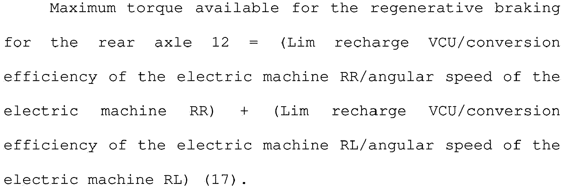
- The control unit VCU is further programmed to calculate and communicate to the brake control unit IPB the maximum value of the torque available for the regenerative braking for the rear axle 12 (step 16).

- The brake control unit IBP is programmed to process:
- the values of the fifth and sixth torque regenerated for the regenerative braking for the electric machines FL, FR, based on the maximum value of the torque available for the Regenerative Braking for the
front axle 11 calculated in step 13) and on a third parameter corresponding to the right - left Front Split coefficient; and - the values of the seventh and eighth torque regenerated for the regenerative braking for the electric machines RR, RL, based on the maximum value of the torque available for the Regenerative Braking for the
rear axle 12 calculated in step 16) and on a fourth parameter corresponding to a right - left Rear Split coefficient; and - communicate said values of the fifth, sixth, seventh and eighth regenerated torque to the control unit VCU.
- The control unit VCU is programmed to cause:
- the electric machine RL to implement a first electric torque corresponding to the sum of the first torque to be implemented for the regenerative engine brake simulation and of the fifth regenerated torque and to exert a corresponding braking torque upon the
wheel 4; - the electric machine RR to implement a second electric torque corresponding to the sum of the second torque to be implemented for the regenerative engine brake simulation and of the sixth regenerated torque and to exert a corresponding braking torque upon the
wheel 5; - the electric machine FR to implement a third electric torque corresponding to the sum of the third torque to be implemented for the regenerative simulation and of the seventh regenerated torque and to exert a corresponding braking torque upon the
wheel 2; and - the electric machine RR to implement a fourth electric torque corresponding to the sum of the fourth torque to be implemented for the regenerative simulation and of the eighth regenerated torque and to exert a corresponding braking torque upon the
wheel 3. - The sum of the first, second, third, fourth, fifth, sixth, seventh, eighth electric torque corresponds to the electric braking torque.
- The brake control unit IPB is programmed to cause the
braking system 10 to generate a braking torque corresponding to the difference between the braking torque requested by the driver by means of thepedal 7 and the sum of the fifth, sixth, seventh and eight torque regenerated for the regenerative braking requested by the brake control unit IPB. - In other words, the brake control unit IPB makes up for the amount of braking torque requested by the driver which cannot be obtained through regenerative braking.
- The operation of the
motor vehicle 1 is described hereinafter starting from an operating condition in which the driver activates thepedal 8 in order to request desired torque values to be delivered towheels - In this condition, the
battery 6 electrically powers the electric machines RL, RR, FL, FR, which generate respective torques acting upon the correspondingwheels - In case the driver releases the
pedal 8, the electronic control unit VCU carries out steps 1-10) described above. - At the end of the aforesaid steps 1-10), the control unit VCU has processed the values of the first, second, third and fourth torque regenerated for the engine brake simulation of the respective electric machines RL, RR, FL, FR.
- In case the driver also activates the
pedal 7, the control unit VCU carries out steps 11-17) described above and the brake control unit IPB communicates to the control unit VCU values of the fifth, sixth, seventh and eighth torque regenerated for the regenerative braking for the respective electric machines RL, RR, FL, FR. - At the point, the control unit VCU causes:
- the electric machine RL to implement a first electric torque corresponding to the sum of the first torque to be implemented for the regenerative engine brake simulation and of the fifth regenerated torque and to exert a corresponding braking torque upon the
wheel 4; - the electric machine RR to implement a second electric torque corresponding to the sum of the second torque to be implemented for the regenerative engine brake simulation and of the sixth regenerated torque and to exert a corresponding braking torque upon the
wheel 5; - the electric machine FR to implement a third electric torque corresponding to the sum of the third torque to be implemented for the regenerative simulation and of the seventh regenerated torque and to exert a corresponding braking torque upon the
wheel 2; and - the electric machine RR to implement a fourth electric torque corresponding to the sum of the fourth torque to be implemented for the regenerative simulation and of the eighth regenerated torque and to exert a corresponding braking torque upon the
wheel 3. - The sum of the first, second, third, fourth, fifth, sixth, seventh, eighth electric torque corresponds to the electric braking torque.
- Finally, the brake control unit IPB causes the
braking system 10 to generate a braking torque corresponding to the difference between the braking torque requested by the driver by means of thepedal 7 and the sum of the fifth, sixth, seventh and eight torque regenerated for the regenerative braking requested by the brake control unit IPB. - The disclosure above reveals evident advantages that can be obtained with the invention.
- More in detail, the control unit VCU is programmed, in case of release of the
pedal 8, to: - process values of the first, second, third and fourth electrical power available for the regenerative engine brake simulation Power available to EnBr for EM RL; Power available to EnBr for EM RR; Power available to EnBr for EM FL; Power available to EnBr for EM FR for respective electric machines RL, RR, FL, FR based on an amount of electrical power still storable Lim Recharge VCU in the
battery 6 and on first operating parameters Right-left Rear EnBr Split, Right-left Rear EnBr Split; - communicate the first, second, third and fourth electrical power available for the regenerative simulation Power available to EnBr for EM RL; Power available to EnBr for EM RR; Power available to EnBr for EM FL; Power available to EnBr for EM FR to the respective electric machines RL, RR, FL, FR and receive from said first, second, third and fourth electric machines RL, RR, FL, FR respective values of a first, second, third and fourth available torque Torque Available to EnBr for EM RL; Torque Available to EnBr for EM RR; Torque Available to EnBr for EM FL; Torque Available to EnBr for EM FR for the regenerative engine brake simulation associated with second parameters of the respective electric machines RL, RR, FL, FR themselves; and
- process a first, second, third and fourth torque to be implemented RL Torque regenerated via engine brake; RR Torque regenerated via engine brake; FL Torque regenerated via engine brake; FR Torque regenerated via engine brake for the respective said first, second, third and fourth electric machine RL, RR, FL, FR.
- In this way, in case of regenerative engine brake simulation following the release of the
pedal 8, the first, second, third and fourth torque to be implemented RL Torque regenerated via engine brake; RR Torque regenerated via engine brake; FL Torque regenerated via engine brake; FR Torque regenerated via engine brake are processed based on the actual amount of electrical power Lim Recharge VCU still storable in thebattery 6, based on desired dynamic features for the split of the power to thewheels - Thanks to this, the quantity of electrical power regenerated in the
battery 6 and, consequently, the values of the first, second, third and fourth implemented electrical torque can be maximized, respecting the limits of thebattery 6 and of the electric machines RL, RR, FL, FR, in case of the regenerative simulation of the engine brake effect following the release of thepedal 8. - As a consequence, on the one hand, it is possible to maximize the amount of electrical power to be made available to the electric machines RL, RR, FL, FR operated as electric motors and, on the other hand, it is possible to reduce the amount of heat to be removed from the
braking system 10 as well as the wear phenomena affecting thebraking system 10. - Similarly, in case of activation of the
brake pedal 7, the brake control unit processes the fifth, sixth, seventh, eighth torque to be implemented for the electric machines RL, RR, FL, FR based on the actual power Lim Recharge VCU still storable in thebattery 6, based on the desired dynamic features for the split of the power to thewheels - Therefore, said values of the fifth, sixth, seventh, eighth torque implemented for the electric machines RL, RR, FL, FR in case of activation of the
brake pedal 7 are also processed respecting the electrical power still storable in thebattery 6 and the features of the electric machines RL, RR, FL, FR as well as the desired dynamic features of themotor vehicle 1, in case of activation of thepedal 7. - This further helps maximize the amount of electrical power that will be available to the electric machines RL, RR, FL, FR operated as electric motors.
- This leads to a reduction of the braking torques and, hence, of the quantity of heat that has to be dissipated by the
braking system 10 and of the wear effects affecting thebraking system 10, even in case of activation of thepedal 7. - Finally, the control unit VCU is programmed to process the third and fourth value of the electrical power available for the regenerative engine brake simulation Power available to EnBr for EM FL; Power available to EnBr for EM FR for the electric machines FL, FR acting upon the
axle 11, based on the electrical power regenerated on theaxle 12 for the regenerative engine brake simulation. - In other words, in case of release of the
pedal 8, the control unit VCU processes the first and second value of the electrical power available for the regenerative engine brake simulation Power available to EnBr for EM RL; Power available to EnBr for EM RR for the electric machines FL, FR operating on theaxle 12 with priority relative to the aforesaid third and fourth value of the electrical power available for the regenerative engine brake simulation Power available to EnBr for EM FL; Power available to EnBr for EM FR for the electric machines FL, FR operating on theaxle 11. - On the contrary, in case of activation of the
pedal 7, the control unit VCU is programmed to process the fifth and sixth value of the electrical power available for the regenerative braking Power available to RegBr for EM RL; Power available to RegBr for EM RR for the electric machines RL, RR acting upon theaxle 12, based on the power currently implemented on theaxle 11. - In other words, in case of activation of the
pedal 7, the control unit VCU processes the seventh and eighth value of the electrical power available for the regenerative braking Power available to RegBr for EM FL; Power available to RegBr for EM FR for the electric machines FL, FR operating on theaxis 11 with priority relative to the aforesaid fifth and sixth value of the electrical power available for the regenerative braking Power available to RegBr for EM RL; Power available to RegBr for EM RR for the electric machines RL, RR operating on theaxis 12. - Therefore, the aforesaid first, second, third, fourth, fifth, sixth, seventh and eighth power can be split among the
wheels pedal 8 or activation of thepedal 7. - Finally, the
motor vehicle 1 and the electric machine control method according to the invention can clearly be subjected to changes and variations, which, though, do not go beyond the scope of protection set forth in the appended claims.
Claims (11)
- A motor-vehicle (1), comprising:- a first and a second wheel (4, 5) forming a first axle (12) of said motor-vehicle (1) arranged at the rear in use;- a third and a fourth wheel (2, 3) forming a second axle (11) of said motor-vehicle (1) arranged at the front in use;- a first and a second electric machine (RL, RR) reversible and operatively connected respectively with said first and second wheels (4, 5);- a third and a fourth electric machine (FL, FR) reversible and operatively connected respectively with said third and fourth wheels (2, 3); and- an electrical power source (6) that is rechargeable and electrically connected with said first, second, third and fourth electric machines (FL, FR, RL, RR) ;said motor-vehicle (1) further comprising:
each of said first, second, third and fourth electric machines (RL, RR, FL, FR) being actuatable as an electric motor to exert respectively a first and second, third and fourth driving torque respectively on said first, second, third and fourth wheels (4, 5; 2, 3), and as an electric generator to use at least a portion of the kinetic energies of respective said first and second, third and fourth wheels (4, 5; 2, 3) and to generate an electrical current that recharges, in use, said source (6);- a first accelerator command (7) actuatable by a driver to request an acceleration of said motor-vehicle (1) ;- a second brake command (8) actuatable by a driver to request a deceleration of said motor-vehicle (1);characterized in that it comprises a control unit (VCU) programmed, in the case of release of said first command (7), to:- steps 3, 7) process values of a first, second, third and fourth electrical power available for the regenerative simulation (Power Available to FrMot for EM RL; Power Available to FrMot for EM RR; Power Available to FrMot for EM FL; Power Available to FrMot for EM FR) of the engine brake for respective said first, second, third and fourth electric machines (RL, RR, FL, FR) based on the amount of electrical power still storable (Lim Recharge VCU) in said source (6) and first operating parameters (Split of FrMot Rear right-left, Split of FrMot Rear right-left) of said motor-vehicle (1), in the case of release of said first command (7);- steps 4, 8) communicate said first, second, third, and fourth electrical power available for the regenerative simulation (Power Available to FrMot for EM RL; Power Available to FrMot for EM RR; Power Available to FrMot for EM FL; Power Available to FrMot for EM FR) to the respective said first, second, third and fourth electric machines (RL, RR, FL, FR) and receive from said first, second, third and fourth electric machines (RL, RR, FL, FR) respective values of a first, second, third and fourth available torque (Torque Available to FrMot for EM RL; Torque Available to FrMot for EM RR; Torque Available to FrMot for EM FL; Torque Available to FrMot for EM FR) for the regenerative simulation of said engine brake associated with second parameters of respective said first, second, third and fourth electric machines (RL, RR, FL, FR) themselves;- steps 5, 9) process a first, second, third and fourth torque to be implemented for the simulation of the engine brake (RL Torque regenerated via engine brake; RR Torque regenerated via engine brake; FL Torque regenerated via engine brake; FR Torque regenerated via engine brake) (RL Torque regenerated via engine brake; RR Torque regenerated via engine brake; FL Torque regenerated via engine brake; FR Torque regenerated via engine brake) for the respective first, second, third and fourth electric machines (RL, RR, FL, FR);
each said first, second, third and fourth torque to be implemented (RL Torque regenerated via engine brake; RR Torque regenerated via engine brake; FL Torque regenerated via engine brake; FR Torque regenerated via engine brake) for the respective first, second, third and fourth electric machines (RL, RR, FL, FR) being associated with the corresponding said values of a first, second, third and fourth available torque (Torque Available to FrMot for EM RL; Torque Available to FrMot for EM RR; Torque Available to FrMot for EM FL; Torque Available to FrMot for EM FR) for the regenerative simulation of said engine brake. - The motor-vehicle according to claim 1, characterized in that said control unit (VCU) is programmed to:- store a table that associates a target torque (Overbraking_TgtTq) that simulates the effect of the engine brake with the forward speed of said motor-vehicle;- distribute said target torque (Overbraking_TgtTq) over said first, second, third and fourth electric machines (RL, RR, FL, FR), so as to process a respective first, second, third and fourth target torques (Overbraking_TgtTq * (1-Split of FrMot Rear right-left) * Split of FrMot Front-Rear; Overbraking_TgtTq * Sp Split of FrMot Rear right-left * Split of FrMot Front-Rear; Overbraking_TgtTq * (1-Split of FrMot Rear right-left) * (1-Split of FrMot Front-Rear); Overbraking_TgtTq * (1-Split of FrMot Rear right-left) * Split of FrMot Front-Rear) ;- steps 5, 9) process said first, second, third and fourth torques to be implemented as the minimum value between the absolute values of each said first, second, third and fourth target torques Overbraking_TgtTq * (1-Split of FrMot Rear right-left) * Split of FrMot Front-Rear; Overbraking_TgtTq * Sp Split of FrMot Rear right-left * Split of FrMot Front-Rear; Overbraking_TgtTq * (1-Split of FrMot Rear right-left) * (1-Split of FrMot Front-Rear); Overbraking_TgtTq * (1-Split of FrMot Rear right-left) * Split of FrMot Front-Rear) and the corresponding said first, second, third and fourth available torques (Torque Available to FrMot for EM RL; Torque Available to FrMot for EM RR; Torque Available to FrMot for EM FL; Torque Available to FrMot for EM FR) for the regenerative simulation of said engine brake.
- The motor-vehicle according to claim 2, characterized in that said control unit (VCU) is programmed to:- communicate said first, second, third and fourth torques to be implemented (RL Torque regenerated via engine brake; RR Torque regenerated via engine brake; FL Torque regenerated via engine brake; FR Torque regenerated via engine brake) to the respective said first, second, third and fourth electric machines (RL, RR, FL, FR);- steps 6, 10) receive from said first, second, third and fourth electric machines (RL, RR, FL, FR) the respective first, second, third and fourth electrical power to be regenerated (Power regenerated via engine brake for EM RL, Power regenerated via engine brake for EM RR, Power regenerated via engine brake for EM FR, Power regenerated via engine brake for EM FR);- step 7) process the values of said third and fourth electrical power available for the regenerative braking (Power Available to FrMot for EM FL; Power Available to FrMot for EM FR) for said third and fourth electric machines (FL, FR), based also on a sum (Rear power regenerated via engine brake) of said first and second electrical power regenerated (Power regenerated via engine brake for EM RL, Power regenerated via engine brake for EM RR) by the respective said first and second electric machines (FL, FR) for the regenerative simulation of said engine brake.
- The motor-vehicle according to claim 3, characterized in that said control unit (VCU) is programmed, in the case of actuating said second command (8), to:- process a sum of the first, second, third and fourth power (Power regenerated via engine brake) regenerated by said first, second, third and fourth electric machines (RL, RR, FL, FR) for the regenerative simulation of said engine brake; and- step 11) process values of a seventh and eighth available electrical power (Power Available to FrReg for EM FL; Power Available to FrReg for EM FR) for the regenerative braking for respective said third and fourth electric machines (FL, FR) based on the amount of electrical power still storable (Lim Recharge VCU) in said source (6), of third operating parameters (Split of Braking F right-left) of said motor-vehicle (1) and of said sum of said first, second, third and fourth power (Power regenerated via engine brake) regenerated by said first, second, third and fourth electric machines (RL, RR, FL, FR) for the regenerative simulation of said engine brake.
- The motor-vehicle according to claim 4, characterized in that said control unit (VCU) is programmed to:- receive a current value of a sum of the third and fourth electrical power implemented (EM F Power implemented) by said third and fourth electric machines (FR, FL);- step 14) process the values of a fifth and sixth electrical power (Power Available to FrReg for EM RL; Power Available to FrReg for EM RR) available for the regenerative braking for respective said first, second electric machines (RL, RR), based on the amount of electrical power still storable (Lim Recharge VCU) in said source (6), of said sum of said third and fourth electrical power implemented (EM F Power implemented) by said third and fourth electric machines (FR, FL), and of the sum of the first, second, third and fourth power (Power regenerated via engine brake) regenerated by said first, second, third and fourth electric machines (RL, RR, FL, FR) for the regenerative simulation of said engine brake.
- The motor-vehicle according to claim 5, characterized in that said first, second, third and fourth electric machines (RL, RR, FL, FR) are programmed to:- receive from said control unit (VCU), at input, respective said fifth, sixth, seventh and eighth electrical power (Power Available to FrMot for EM RL; Power Available to FrMot for EM RR; Power Available to FrReg for EM FL; Power Available to FrReg for EM FR) available for the regenerative braking;- step 15) process a first and second available torque (FrReg Torque Available for EM RL; FrReg Torque Available for EM RR) for the regenerative braking, based on the respective said fifth and sixth electrical power (Power Available to FrMot for EM RL; Power Available to FrMot for EM RR) and said second operating parameters of said first and second electric machines (RL, RR);- step 12) process a third and a fourth available torque (FrReg Torque Available for EM FL; FrReg Torque Available for EM FR) for the regenerative braking, based on respective said seventh and eighth electrical power (Available Power to FrMot for EM FL; Available Power to FrMot for EM FR) and said second operating parameters of said third and fourth second electric machines (FL, FR);- step 15bis) process a first maximum regenerable torque (Maximum Reg Torque Rear Axle) for said first axle (12), based at least on said amount of electrical power still storable (Lim Recharge VCU) in said source (6), and on the angular velocity and the electromechanical efficiency of said first and second electric machines (RL, RR) ;- step 12bis) process a second maximum regenerable torque (Maximum Reg Torque Front Axle) for said second axle (11), based at least on said amount of electrical power still storable (Lim Recharge VCU) in said source (6), and on the angular velocity and the electromechanical efficiency of said third and fourth electric machines (FL, FR) ;- step 16) process a first maximum regenerable torque (FrReg Maximum Torque x Rear) for said first axle (12) as the minimum value between the absolute values of:said first available torque (FrReg Torque Available for EM Rear) for the regenerative braking for said first axle (12) equal to the sum of said first and second available torques (FrReg Torque Available for EM RL; FrReg Torque Available for EM RR) for the regenerative braking, andthe difference between a maximum torque regenerated at said first axle (Maximum Reg Torque Rear Axle) for said first axle (12) and a sum of said first and second torques (Rear Torque regenerated via engine brake) to be implemented for the regenerative simulation of said engine brake; and- step 13) process a second maximum regenerable torque (Maximum FrReg Torque for Front Axle) for said second axle (11) as the minimum value between the absolute values of:said second available torque (FrReg Torque Available for EM FR) for the regenerative braking for said second axle (11) equal to the sum of said third and a fourth available torque (FrReg Torque Available for EM FL; FrReg Torque Available for EM FR) for the regenerative braking, andthe difference between said second maximum available torque (Maximum Reg Torque Front Axle) for the regenerative braking for said second axle (11) and a sum (Front Torque regenerated via engine brake) of said third and fourth regenerated torques for the regenerative simulation of said engine brake.
- The motor-vehicle according to claim 6, characterized in that it comprises:- a braking device (10) adapted to exert a braking torque by friction on said first, second, third and fourth wheels (4, 5, 2, 3);- a brake control unit (IBP) programmed, in the case of activation of said second command (8), to:- receive said first maximum regenerable torque for the regenerative braking (Maximum Reg Torque Rear Axle) by said first and second electric machines (RL, RR) and said second maximum regenerative torque (Maximum Reg Torque Front Axle) for the regenerative braking by said third and fourth electric machines (FL, FR);- process a fifth and a sixth torque implemented for the regenerative braking for the respective said first and second electric machines (RL, RR), based on said first maximum regenerable torque for the regenerative braking (Maximum Reg Torque Rear Axle);- process a seventh and eighth torque implemented for the regenerative braking for the respective third and fourth electric machines (FL, FR), based on said second maximum regenerable torque for the regenerative braking (Maximum Reg Torque Front Axle);- communicate said fifth, sixth, seventh, and eighth torques to be implemented for the regenerative braking to said control unit (VCU);- process a braking torque value for said braking device (7) based on said command set, in use, on said second pedal (8) and said first, second, third, fourth, fifth, sixth, seventh and eighth torque values implemented for said regenerative braking.
- The motor-vehicle according to claim 7, characterized in that said control unit (VCU) is programmed to command:- said first electric machine (FL) to sum said first torque to be implemented for the simulation of said engine brake (RL Torque regenerated via engine brake) and the fifth torque to be implemented for the regenerative braking;- said second electric machine (FR) to sum said second torque to be implemented for the simulation of said engine brake (RR Torque regenerated via engine brake) and the sixth torque to be implemented for the regenerative braking;- said third electric machine (RL) to sum said third torque to be implemented for the simulation of said engine brake (RL Torque regenerated via engine brake) and said seventh torque to be implemented for the regenerative braking; and- said fourth electric machine (RR) to implement said fourth torque to be implemented for the simulation of said engine brake (RR Torque regenerated via engine brake) and said eighth torque to be implemented for the regenerative braking.
- The motor-vehicle according to any one of the preceding claims, characterized in that it is without a heat engine.
- A method to control a first, second, third and fourth reversible electric machine (RL, RR, FL, FR) of a motor-vehicle (1), comprising the steps of:i) operatively connecting a first and a second electric machine (RL, RR) respectively with a first and a second wheel (4, 5) of said motor-vehicle (1) forming a first axle (12) of said motor-vehicle (1) arranged at the rear in use:ii) operatively connecting a third and a fourth electric machine (FL, FR) respectively with a third and a fourth wheel (2, 3) of said motor-vehicle (1) forming a second axle (11) of said motor-vehicle (1) arranged at the front in use;iii) electrically connecting a rechargeable electrical power source (6) electrically connected with said first, second, third and fourth electric machines (RL, RR, FL, FR) ;iv) operating each said first, second, third and fourth electric machines (RL, RR, FL, FR) as an electric motor to exert respectively a first and second, third and fourth driving torque respectively on said first, second, third and fourth wheels (4, 5; 2, 3), in the case of actuating a first accelerator command (7) of said motor-vehicle (1);v) operating each said first, second, third and fourth electric machines (FL, FR, RL, RR) as an electric generator to use at least a portion of the kinetic energies of respective said first, second, third and fourth wheels (4, 5; 2, 3) and to generate an electrical current that recharges, in use, said source (6), in the case of actuating a second brake command (8) of said motor-vehicle (1) ;characterized in that it comprises the further steps, in the case of release of said first command (7), of:- vi) processing values of a first, second, third and fourth electrical power available for the regenerative simulation (Power Available to FrMot for EM RL; Power Available to FrMot for EM RR; Power Available to FrMot for EM FL; Power Available to FrMot for EM FR) of the engine brake for respective said first, second, third and fourth electric machines (RL, RR, FL, FR) based on the amount of electrical power still storable (Lim Recharge VCU) in said source (6) and first operating parameters (Split of FrMot Rear right-left, Split of FrMot Rear right-left) of said motor-vehicle (1), in the case of release of said first command (7) (steps 3, 7);- vii) communicate said first, second, third and fourth electrical power available for the regenerative simulation (Power Available to FrMot for EM RL; Power Available to FrMot for EM RR; Power Available to FrMot for EM FL; Power Available to FrMot for EM FR) to the respective said first, second, third and fourth electric machines (RL, RR, FL, FR) and receive from said first, second, third and fourth electric machines (RL, RR, FL, FR) respective values of a first, second, third and fourth available torque (Torque Available to FrMot for EM RL; Torque Available to FrMot for EM RR; Torque Available to FrMot for EM FL; Torque Available to FrMot for EM FR) for the regenerative simulation of said engine brake associated with second parameters of respective said first, second, third and fourth electric machines (RL, RR, FL, FR) themselves (steps 4, 8); and- viii) process a first, second, third and fourth torque to be implemented for the simulation of the engine brake (RL Torque regenerated via engine brake; RR Torque regenerated via engine brake; FL Torque regenerated via engine brake; FR Torque regenerated via engine brake) (RL Torque regenerated via engine brake; RR Torque regenerated via engine brake; FL Torque regenerated via engine brake; FR Torque regenerated via engine brake) for the respective first, second, third and fourth electric machines (RL, RR, FL, FR) (steps 5, 9) ;
each said first, second, third and fourth torque to be implemented (RL Torque regenerated via engine brake; RR Torque regenerated via engine brake; FL Torque regenerated via engine brake; FR Torque regenerated via engine brake) for the respective first, second, third and fourth electric machines (RL, RR, FL, FR) being associated with the corresponding said first, second, third and fourth available torque values (Torque Available to FrMot for EM RL; Torque Available to FrMot for EM RR; Torque Available to FrMot for EM FL; Torque Available to FrMot for EM FR) for the regenerative simulation of said engine brake. - A computer product loadable in a control unit (VCU) of a motor-vehicle (1) and adapted, when run, to implement the steps of a method according to claim 10.
Applications Claiming Priority (1)
| Application Number | Priority Date | Filing Date | Title |
|---|---|---|---|
| IT102022000012946A IT202200012946A1 (en) | 2022-06-20 | 2022-06-20 | MOTOR VEHICLE |
Publications (1)
| Publication Number | Publication Date |
|---|---|
| EP4306352A1 true EP4306352A1 (en) | 2024-01-17 |
Family
ID=83271628
Family Applications (1)
| Application Number | Title | Priority Date | Filing Date |
|---|---|---|---|
| EP23179934.7A Pending EP4306352A1 (en) | 2022-06-20 | 2023-06-19 | Motor vehicle with wheel hub motors |
Country Status (5)
| Country | Link |
|---|---|
| US (1) | US20230406111A1 (en) |
| EP (1) | EP4306352A1 (en) |
| JP (1) | JP2024000536A (en) |
| CN (1) | CN117261622A (en) |
| IT (1) | IT202200012946A1 (en) |
Citations (5)
| Publication number | Priority date | Publication date | Assignee | Title |
|---|---|---|---|---|
| US6155365A (en) * | 1998-05-12 | 2000-12-05 | Chrysler Corporation | Brake blending strategy for a hybrid vehicle |
| WO2013088554A1 (en) * | 2011-12-15 | 2013-06-20 | パイオニア株式会社 | Vehicle drive device |
| US20180361856A1 (en) * | 2017-06-15 | 2018-12-20 | Ford Global Technologies, Llc | Methods and system for regenerative hybrid vehicle braking |
| US20190275994A1 (en) * | 2018-03-07 | 2019-09-12 | Ford Global Technologies, Llc | Vehicle wheel torque control systems and methods |
| US20220024306A1 (en) * | 2020-07-27 | 2022-01-27 | Ford Global Technologies, Llc | Manual torque vectoring |
Family Cites Families (7)
| Publication number | Priority date | Publication date | Assignee | Title |
|---|---|---|---|---|
| US20040263099A1 (en) * | 2002-07-31 | 2004-12-30 | Maslov Boris A | Electric propulsion system |
| US8428840B2 (en) * | 2010-10-29 | 2013-04-23 | GM Global Technology Operations LLC | Method for controlling torque at one or more wheels of a vehicle |
| US20130162009A1 (en) * | 2011-12-22 | 2013-06-27 | Coda Automotive, Inc. | Electric vehicle regenerative braking system |
| GB2508665B (en) * | 2012-12-10 | 2015-11-25 | Jaguar Land Rover Ltd | Hybrid electric vehicle control system and method |
| JP6990115B2 (en) * | 2018-01-15 | 2022-01-12 | 日立Astemo株式会社 | Motor vehicle control device, motor vehicle control system, and motor vehicle control method |
| US11440417B2 (en) * | 2020-02-19 | 2022-09-13 | Dana Automotive Systems Group, Llc | System and method for adjusting vehicle performance |
| JP7478638B2 (en) * | 2020-09-30 | 2024-05-07 | 日立Astemo株式会社 | Vehicle control device, vehicle control method, and vehicle control system |
-
2022
- 2022-06-20 IT IT102022000012946A patent/IT202200012946A1/en unknown
-
2023
- 2023-06-15 US US18/335,249 patent/US20230406111A1/en active Pending
- 2023-06-19 EP EP23179934.7A patent/EP4306352A1/en active Pending
- 2023-06-19 JP JP2023099976A patent/JP2024000536A/en active Pending
- 2023-06-20 CN CN202310733671.8A patent/CN117261622A/en active Pending
Patent Citations (5)
| Publication number | Priority date | Publication date | Assignee | Title |
|---|---|---|---|---|
| US6155365A (en) * | 1998-05-12 | 2000-12-05 | Chrysler Corporation | Brake blending strategy for a hybrid vehicle |
| WO2013088554A1 (en) * | 2011-12-15 | 2013-06-20 | パイオニア株式会社 | Vehicle drive device |
| US20180361856A1 (en) * | 2017-06-15 | 2018-12-20 | Ford Global Technologies, Llc | Methods and system for regenerative hybrid vehicle braking |
| US20190275994A1 (en) * | 2018-03-07 | 2019-09-12 | Ford Global Technologies, Llc | Vehicle wheel torque control systems and methods |
| US20220024306A1 (en) * | 2020-07-27 | 2022-01-27 | Ford Global Technologies, Llc | Manual torque vectoring |
Also Published As
| Publication number | Publication date |
|---|---|
| IT202200012946A1 (en) | 2023-12-20 |
| JP2024000536A (en) | 2024-01-05 |
| US20230406111A1 (en) | 2023-12-21 |
| CN117261622A (en) | 2023-12-22 |
Similar Documents
| Publication | Publication Date | Title |
|---|---|---|
| US7216943B2 (en) | Hybrid vehicle | |
| CN108602452B (en) | Controller and method for motor vehicle | |
| JP4659390B2 (en) | Vehicle braking device and vehicle braking method | |
| CN108290502B (en) | Controller and method for a motor vehicle | |
| US6406105B1 (en) | Brake system of hybrid type vehicle having front and rear regeneration brakes of different efficiencies | |
| CN102481907A (en) | Brake control device | |
| US20120109483A1 (en) | Method for controlling torque at one or more wheels of a vehicle | |
| WO2015068800A1 (en) | Braking force control system | |
| KR20100094993A (en) | Method for controlling the regenerative braking of a vehicle including at least one electric motor | |
| KR101714238B1 (en) | Braking control method for eco-friendly vehicle | |
| JP6329105B2 (en) | Driving force control device for four-wheel drive vehicle | |
| US20110130909A1 (en) | System and method for controlling a four wheel drive vehicle | |
| US11440403B2 (en) | Control apparatus for electric vehicle, control system for electric vehicle, and control method for electric vehicle | |
| CN116215246B (en) | Method, device and storage medium for distributing braking torque of front and rear axles of electric vehicles under combined braking | |
| US9789864B2 (en) | Devices and methods for distributing an overall target torque specification | |
| JP2018033290A (en) | Electric car | |
| US20230406111A1 (en) | Motor vehicle | |
| US20220048482A1 (en) | Method for distributing a braking torque, requested by a driver, over the axles of a motor vehicle | |
| US11577605B1 (en) | All-wheel-drive electric vehicle | |
| CN114430719B (en) | vehicle braking device | |
| Shuklynov et al. | Simulation of the combined braking control system for hybrid electric vehicles | |
| JP2017136885A (en) | Hybrid vehicle and control method thereof | |
| CN106515719B (en) | By with subtract malaria system combination power of regeneration expanded into up to vehicle dynamic limit | |
| WO2025203187A1 (en) | Vehicle | |
| Jang et al. | Study of P2+ P4 AWD HEV Architecture Exploration |
Legal Events
| Date | Code | Title | Description |
|---|---|---|---|
| PUAI | Public reference made under article 153(3) epc to a published international application that has entered the european phase |
Free format text: ORIGINAL CODE: 0009012 |
|
| STAA | Information on the status of an ep patent application or granted ep patent |
Free format text: STATUS: THE APPLICATION HAS BEEN PUBLISHED |
|
| AK | Designated contracting states |
Kind code of ref document: A1 Designated state(s): AL AT BE BG CH CY CZ DE DK EE ES FI FR GB GR HR HU IE IS IT LI LT LU LV MC ME MK MT NL NO PL PT RO RS SE SI SK SM TR |
|
| STAA | Information on the status of an ep patent application or granted ep patent |
Free format text: STATUS: REQUEST FOR EXAMINATION WAS MADE |
|
| 17P | Request for examination filed |
Effective date: 20240716 |
|
| RBV | Designated contracting states (corrected) |
Designated state(s): AL AT BE BG CH CY CZ DE DK EE ES FI FR GB GR HR HU IE IS IT LI LT LU LV MC ME MK MT NL NO PL PT RO RS SE SI SK SM TR |