EP4306300A1 - Battery cell manufacturing device - Google Patents
Battery cell manufacturing device Download PDFInfo
- Publication number
- EP4306300A1 EP4306300A1 EP22767542.8A EP22767542A EP4306300A1 EP 4306300 A1 EP4306300 A1 EP 4306300A1 EP 22767542 A EP22767542 A EP 22767542A EP 4306300 A1 EP4306300 A1 EP 4306300A1
- Authority
- EP
- European Patent Office
- Prior art keywords
- battery cell
- manufacturing
- sealing portion
- molded groove
- pressure roller
- Prior art date
- Legal status (The legal status is an assumption and is not a legal conclusion. Google has not performed a legal analysis and makes no representation as to the accuracy of the status listed.)
- Pending
Links
Images




Classifications
-
- H—ELECTRICITY
- H01—ELECTRIC ELEMENTS
- H01M—PROCESSES OR MEANS, e.g. BATTERIES, FOR THE DIRECT CONVERSION OF CHEMICAL ENERGY INTO ELECTRICAL ENERGY
- H01M50/00—Constructional details or processes of manufacture of the non-active parts of electrochemical cells other than fuel cells, e.g. hybrid cells
- H01M50/10—Primary casings; Jackets or wrappings
- H01M50/102—Primary casings; Jackets or wrappings characterised by their shape or physical structure
- H01M50/105—Pouches or flexible bags
-
- H—ELECTRICITY
- H01—ELECTRIC ELEMENTS
- H01M—PROCESSES OR MEANS, e.g. BATTERIES, FOR THE DIRECT CONVERSION OF CHEMICAL ENERGY INTO ELECTRICAL ENERGY
- H01M10/00—Secondary cells; Manufacture thereof
- H01M10/04—Construction or manufacture in general
- H01M10/0404—Machines for assembling batteries
-
- H—ELECTRICITY
- H01—ELECTRIC ELEMENTS
- H01M—PROCESSES OR MEANS, e.g. BATTERIES, FOR THE DIRECT CONVERSION OF CHEMICAL ENERGY INTO ELECTRICAL ENERGY
- H01M50/00—Constructional details or processes of manufacture of the non-active parts of electrochemical cells other than fuel cells, e.g. hybrid cells
- H01M50/10—Primary casings; Jackets or wrappings
- H01M50/116—Primary casings; Jackets or wrappings characterised by the material
- H01M50/124—Primary casings; Jackets or wrappings characterised by the material having a layered structure
-
- B—PERFORMING OPERATIONS; TRANSPORTING
- B29—WORKING OF PLASTICS; WORKING OF SUBSTANCES IN A PLASTIC STATE IN GENERAL
- B29C—SHAPING OR JOINING OF PLASTICS; SHAPING OF MATERIAL IN A PLASTIC STATE, NOT OTHERWISE PROVIDED FOR; AFTER-TREATMENT OF THE SHAPED PRODUCTS, e.g. REPAIRING
- B29C53/00—Shaping by bending, folding, twisting, straightening or flattening; Apparatus therefor
- B29C53/02—Bending or folding
- B29C53/04—Bending or folding of plates or sheets
- B29C53/043—Bending or folding of plates or sheets using rolls or endless belts
-
- B—PERFORMING OPERATIONS; TRANSPORTING
- B29—WORKING OF PLASTICS; WORKING OF SUBSTANCES IN A PLASTIC STATE IN GENERAL
- B29C—SHAPING OR JOINING OF PLASTICS; SHAPING OF MATERIAL IN A PLASTIC STATE, NOT OTHERWISE PROVIDED FOR; AFTER-TREATMENT OF THE SHAPED PRODUCTS, e.g. REPAIRING
- B29C53/00—Shaping by bending, folding, twisting, straightening or flattening; Apparatus therefor
- B29C53/36—Bending and joining, e.g. for making hollow articles
-
- B—PERFORMING OPERATIONS; TRANSPORTING
- B29—WORKING OF PLASTICS; WORKING OF SUBSTANCES IN A PLASTIC STATE IN GENERAL
- B29C—SHAPING OR JOINING OF PLASTICS; SHAPING OF MATERIAL IN A PLASTIC STATE, NOT OTHERWISE PROVIDED FOR; AFTER-TREATMENT OF THE SHAPED PRODUCTS, e.g. REPAIRING
- B29C66/00—General aspects of processes or apparatus for joining preformed parts
- B29C66/01—General aspects dealing with the joint area or with the area to be joined
- B29C66/03—After-treatments in the joint area
- B29C66/032—Mechanical after-treatments
- B29C66/0324—Reforming or reshaping the joint, e.g. folding over
-
- B—PERFORMING OPERATIONS; TRANSPORTING
- B29—WORKING OF PLASTICS; WORKING OF SUBSTANCES IN A PLASTIC STATE IN GENERAL
- B29L—INDEXING SCHEME ASSOCIATED WITH SUBCLASS B29C, RELATING TO PARTICULAR ARTICLES
- B29L2031/00—Other particular articles
- B29L2031/34—Electrical apparatus, e.g. sparking plugs or parts thereof
- B29L2031/3468—Batteries, accumulators or fuel cells
-
- H—ELECTRICITY
- H01—ELECTRIC ELEMENTS
- H01M—PROCESSES OR MEANS, e.g. BATTERIES, FOR THE DIRECT CONVERSION OF CHEMICAL ENERGY INTO ELECTRICAL ENERGY
- H01M10/00—Secondary cells; Manufacture thereof
- H01M10/04—Construction or manufacture in general
- H01M10/0431—Cells with wound or folded electrodes
-
- H—ELECTRICITY
- H01—ELECTRIC ELEMENTS
- H01M—PROCESSES OR MEANS, e.g. BATTERIES, FOR THE DIRECT CONVERSION OF CHEMICAL ENERGY INTO ELECTRICAL ENERGY
- H01M10/00—Secondary cells; Manufacture thereof
- H01M10/04—Construction or manufacture in general
- H01M10/0436—Small-sized flat cells or batteries for portable equipment
-
- H—ELECTRICITY
- H01—ELECTRIC ELEMENTS
- H01M—PROCESSES OR MEANS, e.g. BATTERIES, FOR THE DIRECT CONVERSION OF CHEMICAL ENERGY INTO ELECTRICAL ENERGY
- H01M50/00—Constructional details or processes of manufacture of the non-active parts of electrochemical cells other than fuel cells, e.g. hybrid cells
- H01M50/10—Primary casings; Jackets or wrappings
- H01M50/116—Primary casings; Jackets or wrappings characterised by the material
- H01M50/117—Inorganic material
- H01M50/119—Metals
-
- Y—GENERAL TAGGING OF NEW TECHNOLOGICAL DEVELOPMENTS; GENERAL TAGGING OF CROSS-SECTIONAL TECHNOLOGIES SPANNING OVER SEVERAL SECTIONS OF THE IPC; TECHNICAL SUBJECTS COVERED BY FORMER USPC CROSS-REFERENCE ART COLLECTIONS [XRACs] AND DIGESTS
- Y02—TECHNOLOGIES OR APPLICATIONS FOR MITIGATION OR ADAPTATION AGAINST CLIMATE CHANGE
- Y02E—REDUCTION OF GREENHOUSE GAS [GHG] EMISSIONS, RELATED TO ENERGY GENERATION, TRANSMISSION OR DISTRIBUTION
- Y02E60/00—Enabling technologies; Technologies with a potential or indirect contribution to GHG emissions mitigation
- Y02E60/10—Energy storage using batteries
-
- Y—GENERAL TAGGING OF NEW TECHNOLOGICAL DEVELOPMENTS; GENERAL TAGGING OF CROSS-SECTIONAL TECHNOLOGIES SPANNING OVER SEVERAL SECTIONS OF THE IPC; TECHNICAL SUBJECTS COVERED BY FORMER USPC CROSS-REFERENCE ART COLLECTIONS [XRACs] AND DIGESTS
- Y02—TECHNOLOGIES OR APPLICATIONS FOR MITIGATION OR ADAPTATION AGAINST CLIMATE CHANGE
- Y02P—CLIMATE CHANGE MITIGATION TECHNOLOGIES IN THE PRODUCTION OR PROCESSING OF GOODS
- Y02P70/00—Climate change mitigation technologies in the production process for final industrial or consumer products
- Y02P70/50—Manufacturing or production processes characterised by the final manufactured product
Definitions
- the present disclosure relates to an apparatus for manufacturing a battery cell.
- a rechargeable battery capable of charging and discharging has been widely used as an energy source for wireless mobile devices.
- secondary batteries are attracting attention as a power source for electric vehicles (EVs), hybrid electric vehicles (HEVs) and the like, which are proposed as a way to solve air pollution issues, such as for gasoline, diesel vehicles and the like, using fossil fuels.
- the battery cell undergoes a process of folding the bonding portion (or the sealing portion) of the casing of the battery cell during the manufacturing process.
- Folding refers to bending or folding at least a portion of the sealing portion of the battery cell casing toward the body portion of the battery cell. Since the area of the sealing portion of the battery cell is very narrow compared to the size of the entire battery cell, it is difficult to fold in the desired position, and during the folding process, unnecessary pressure is applied to the electrode assembly or the sealing portion is destroyed, causing a problem in which a battery cell is defective.
- An aspect of the present disclosure is to increase efficiency and reliability of a manufacturing process of a battery cell.
- an aspect of the present disclosure is to enable a process of folding a casing material of a pouch-type battery cell to be stably performed.
- an apparatus for manufacturing a battery cell includes a body portion having rigidity; and a molded groove configured to allow at least a portion of the sealing portion of the battery cell to be inserted and passed therethrough.
- the molded groove penetrates the body portion in a first direction, and a shape of the molded groove is changed in the first direction.
- the molded groove may comprise an inlet disposed at one end of the body portion in the first direction and configured to allow the sealing portion to be inserted; and an outlet disposed at the other end in the first direction and configured to allow the sealing portion to exit.
- shapes of the inlet and the outlet may be different from each other.
- the molded groove may include a first molded groove open in a second direction, perpendicular to the first direction, at one side of the body portion; and a second molded groove connected to the first molded groove and inclined with respect to the first molded groove.
- an angle between the first molded groove and the second molded groove may be continuously changed in the first direction.
- the angle between the first molded groove and the second molded groove may gradually decrease in the first direction.
- an angle between the first molded groove and the second molded groove at an end of the body portion in the first direction may be perpendicular.
- the body portion may be movable in the first direction.
- an apparatus for manufacturing a battery cell includes a support unit configured to support a sealing portion of a battery cell, wherein one side of the support unit is configured to face a body portion in which an electrode assembly of the battery cell is accommodated; and a folding unit facing the other side opposite to the one side of the support unit and configured to bend the sealing portion of the battery cell.
- the folding unit is configured to be movable along the other side of the support unit to bend the sealing portion of the battery cell.
- the support unit may include a first support member and a second support member configured to be movable in different directions, and the first support member and the second support member are configured such that the sealing portion of the battery cell can be fixed therebetween.
- first support member and the second support member may be configured to support a boundary between the body portion and the sealing portion.
- the folding unit may include a pressure roller configured to be movablefrom a first position facing the first support member to a second position facing the second support member, and the pressure roller may be configured to bend the sealing portion so that the sealing portion comes into contact with the second support member.
- the folding unit may further include an auxiliary roller supporting the pressure roller, and the auxiliary roller may be configured to move together in contact with the pressure roller.
- a diameter of the auxiliary roller may be equal to or less than a diameter of the pressure roller.
- the pressure roller and the auxiliary roller may be respectively rotatable, and an axis of rotation of the auxiliary roller may be parallel to an axis of rotation of the pressure roller.
- the auxiliary roller may include a first auxiliary roller and a second auxiliary roller in contact with different portions of the pressure roller, and an angle between a virtual line connecting a center of rotation of the pressure roller and a center of rotation of the first auxiliary roller and a virtual line connecting the center of rotation of the pressure roller and a center of rotation of the second auxiliary roller may be an acute angle.
- the sealing portion of the battery cell may be stably folded at a desired angle.
- the apparatus for manufacturing a battery cell by effectively folding a partial surface of the sealing portion of the battery cell, a phenomenon in which the sealing of the sealing portion is released may be prevented.
- the volume of the electrode assembly disposed in the inner space of the module housing having the same size may be increased.
- first may be referred to as a second component
- second component may also be referred to as a first component
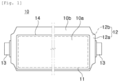
- FIG. 1 illustrates a battery cell 10.
- FIG. 2 illustrates a process in which a sealing portion 10b of the battery cell 10 is deformed according to the folding process according to the embodiments.
- a folding process of the battery cell 10 will be described with reference to FIGS. 1 to 2 .
- the battery cell 10 may be a pouch-type battery cell.
- the battery cell 10 includes an electrode assembly 11 and a casing 12 (or a pouch) surrounding the electrode assembly 11.
- the electrode assembly 11 is provided in a form in which positive and negative plates are sequentially stacked, and may further include a separator between the positive and negative plates.
- the casing 12 is provided in the form of enclosing the electrode assembly 11 to configure the exterior of the battery cell 10, and may protect the electrode assembly 11 from external impact. In addition, the casing 12 may seal the electrode assembly 11 from the outside.
- the battery cell 10 includes an electrode tab 13 extending in a longitudinal direction, and the electrode tab 13 is connected to an electrode plate (a positive electrode plate or a negative electrode plate) of the electrode assembly 11.
- the casing 12 may be provided in the form of sandwiching the electrode assembly 11 from both sides.
- the casing 12 may include a first casing 12a enclosing an upper portion of the electrode assembly 11 and a second casing 12b enclosing a lower portion of the electrode assembly 11.
- the inner portion of the casing 12 surrounds the electrode assembly 11, and the peripheral portion may be bonded to a peripheral portion of the opposite casing 12.
- the first casing 12a and the second casing 12b are bonded to each other at the edge portion.
- the first casing 12a and the second casing 12b may be provided as a single casing 12.
- one casing 12 surrounds the electrode assembly 11 over the top and bottom, and may be bonded on the periphery of the other side portions (for example, the right long side and two short sides of the battery cell 10 of FIG. 1 ) except for one side (for example, the left long side of the battery cell 10 in FIG. 1 ) of the electrode assembly 11, to seal the electrode assembly 11 from the outside.
- the battery cell 10 may include a body portion 10a and a sealing portion 10b.
- the body portion 10a accommodates the electrode assembly 11 and means a portion having a thickness corresponding to the electrode assembly 11.
- a cross-section of the body portion 10a may include the electrode assembly 11 and the casing 12 covering both sides of the electrode assembly 11.
- the sealing portion 10b may mean a thin portion extending from at least one edge of the body portion 10a in the longitudinal direction (or in a direction perpendicular to the stacking direction).
- the sealing portion 10b may be a portion in which the casing is overlapped and joined when one sheet of the casing is folded.
- the cross-section of the sealing portion 10b may be composed of two layers of casing.
- the sealing portion 10b of the battery cell 10 may be gradually folded through a plurality of folding processes.
- the respective folding processes may be performed by one folding process unit or sequentially by individual folding process units .
- the sealing portion 10b of the battery cell 10 is folded one or more times through a plurality of folding processes, and for example, is folded about 90 degrees in a first folding process, and may be folded again by 90 degrees in a second folding process, to be in a folded state by 180 degrees.
- a third folding process it may be additionally folded by 90 degrees.
- the sealing portion 10b may be positioned adjacent to the side wall (14 of FIG. 1 ) of the body portion 10a.
- the sealing portion 10b illustrated in FIG. 2 means a portion in which the electrode tab 13 is not located, from among portions remaining after wrapping the electrode assembly 11 among the casing 12 of the battery cell 10 of FIG. 1 . That is, the sealing portion 10b of FIG. 2 may correspond to the upper part of the battery cell 10 among the extra parts remaining after the casing 12 of the battery cell 10 of FIG. 1 surrounds the electrode assembly 11. However, this is an example, and when a sealing portion is formed on four surfaces by overlapping two sheets of the casing 12, a process of folding the upper portion and the lower portion where the electrode tab 130 is not located may be performed several times.
- the sealing portion 10b described in the following FIGS. 3 to 7 corresponds to the sealing portion 10b of FIG. 2 , and overlapping descriptions will be omitted.
- folding process is illustrated in FIG. 2 as going through four steps, this is only an example, and the folding process may include two, three, or five or more folding processes.
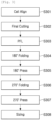
- FIG. 3 a folding process according to embodiments will be described in more detail.
- the battery cell and constituent portions thereof described in FIG. 3 correspond to the battery cell and the constituent portions described in FIGS. 1 and 2 , and overlapping descriptions will be omitted.
- the positions of the battery cells are aligned in an alignment step (S301) . That is, in the alignment step, in order to accurately fold the sealing portion in a desired position, the battery cell is positioned appropriately.
- a cutting step (S302) of cutting to a predetermined length is performed so that the sealing portion of the battery cell may be folded by a specified length.
- a PFL (Pre Forming Location) step (S303) of pre-forming the corresponding folding line to prevent meandering during folding is performed.
- the sealing portion of the battery cell that has undergone the PFL step S303 is folded at least once in a first folding step S304 so that the end of the sealing portion faces the sidewall of the body portion of the battery cell. That is, in the first folding step (S304), the sealing portion is folded by 180 degrees (refer to the third figure of FIG. 2 ).
- a first pressing step (S305) is performed by pressing the sealing portion folded by 180 degrees with heat and pressure. Heat and pressure are applied to the folded part to maintain the folded shape.
- the folded sealing portion is folded at least once again in a second folding step (S306) so that the sealing portion faces in the width direction of the battery cell. That is, in the second folding step (S306), the sealing portion is folded by 90 degrees in the same direction as the folded direction in the first folding step (refer to the fourth figure in FIG. 2 ).
- the folded sealing portion is pressed and molded by heat and pressure. Heat and pressure are applied to the folded part to maintain the folded shape.
- a sizing step (S308), the folded sealing portion is passed through a sizing roller to form the sealing portion adjacent to the sidewall of the body portion of the battery cell. Accordingly, the folded sealing portion is adjacent to the sidewall of the body portion of the battery cell at an acute angle.
- the first folding step (for example, S304 of FIG. 3 ) of folding the sealing portion by 180 degrees may be performed by an apparatus for manufacturing a first battery cell described in FIG. 4 or FIG. 5 and an apparatus for manufacturing a second battery cell described in FIGS. 5 to 8 .
- the sealing portion may be first folded by 90 degrees by the apparatus for manufacturing a first battery cell and then further folded by 90 degrees by the apparatus for manufacturing a second battery cell, to be folded by a total of 180 degrees.
- the apparatus for manufacturing a first battery cell folds the sealing portion 10b of the battery cell 10.
- the apparatus for manufacturing a first battery cell continuously folds the sealing portion 10b of the battery cell 10 such that the end of the sealing portion 10b of the battery cell 10 faces the body portion 10a of the battery cell 10. That is, the sealing portion 10b of the battery cell 10 may be folded by 90 degrees by the apparatus for manufacturing a first battery cell.
- the apparatus for manufacturing a first battery cell may include a plurality of folding units 410, 420, 430, and 440, and the plurality of folding units 410, 420, 430 and 440 may be arranged side by side in one direction.
- the folding units 410, 420, 430, and 440 may include a first folding unit 410, a second folding unit 420, a third folding unit 430, and a fourth folding unit 440, which gradually bend the sealing portion 10b.
- the folding units 410, 420, 430, and 440 may move relative to the battery cell 10 to bend the sealing portion 10b of the battery cell at various angles.
- one folding unit may include at least two rollers (for example, 411 and 412) .
- the first folding unit 410 may include a first roller 411 and a second roller 412 having rotation axes a1 and b1 parallel to each other.
- the sealing portion 10b of the battery cell 10 may pass between the first roller 411 and the second roller 412 while being in contact with the roller surfaces of the first roller 411 and the second roller 412.
- the distance between the two rollers 411 and 412 may be set differently according to the thickness of the casing of the battery cell 10 to be folded by the apparatus for manufacturing a first battery cell.
- the two rollers 411 and 412 may move to each other to adjust positions such that the casing of about 270 um may be sandwiched between the two rollers 411 and 412.
- the plurality of folding units 410, 420, 430, and 440 may be provided by sequentially different angles at which they are installed in one direction. That is, the plurality of folding units 410, 420, 430, and 440 arranged from the inlet side to the outlet side of the apparatus for manufacturing a first battery cell may be arranged side by side in the transfer direction of the battery cell 10 at installation angles thereof changed sequentially.
- the first folding unit 410 installed first on the inlet side of the apparatus for manufacturing a first battery cell may include rollers 411 and 412 having rotation axes a1 and b1 parallel to a reference plane (for example, the ground), the second folding unit 420 installed to be spaced apart from the first folding unit in the transport direction of the battery cell 10 includes rollers 421 and 422 having rotation axes a2 and b2 at a predetermined angle with the reference plane (the ground), and the third folding unit 430 installed on the rear of the second folding unit 420 may include rollers 431 and 432 having rotation axes a3 and b3 having a greater angle with the reference plane (ground).
- a reference plane for example, the ground
- the second folding unit 420 installed to be spaced apart from the first folding unit in the transport direction of the battery cell 10 includes rollers 421 and 422 having rotation axes a2 and b2 at a predetermined angle with the reference plane (the ground)
- the angle formed by the rollers of the folding unit with the reference plane (ground) gradually increases in the transport direction of the battery cell 10, and the fourth folding unit 440 finally installed on the outlet side of the apparatus for manufacturing a first battery cell may include rollers 441 and 442 having rotation axes a4 and b4 perpendicular to the reference plane (ground).
- the rollers included in each of the folding units 410, 420, 430, and 440 may have different sizes.
- the upper roller (that is, the second roller in respective folding units) of the folding units 410, 420, 430 and 440 gradually moves in the transport direction of the battery cell 10 to approach the body portion 10a of the battery cell 10, and may thus be configured to have a gradually smaller size in order to prevent interference with the body portion 10a. That is, as illustrated in FIG. 4 , the size of the second roller 442 included in the fourth folding unit 440 may be smaller than the size of the second roller 412 included in the first folding unit 410.
- the sizes of the rollers included in the folding units 410, 420, 430, and 440 are not limited to the illustration, and may be variously modified within a range that does not interfere with the battery cell 10.
- FIG. 4 illustrates a total of four folding units 410, 420, 430, and 440, but this is only an example, and the number of folding units 410, 420, 430 and 440 included in the apparatus for manufacturing a first battery cell may be 2, 3 or 5 or more.
- the number of folding units 410, 420, 430 and 440 installed at different angles may be changed according to how the folding angle is divided.
- the battery cell 10 transferred to the apparatus for manufacturing a first battery cell is inserted between the first roller 411 and the second roller 412 of the first folding unit 410 in which the sealing portion 10b is provided on the inlet side of the apparatus for manufacturing a first battery cell.
- the sealing portion 10b passes through the respective rollers 411, 412, 421, 422, 431, 432, 441 and 442 provided in the plurality of folding units 410, 420, 430 and 440 and is folded corresponding to the angle at which the folding units 410, 420, 430 and 440 are installed.
- the sealing portion 10b of the battery cell 10 enters the first folding unit 410 provided on the inlet side of the apparatus for manufacturing a first battery cell, in a state oriented in a direction parallel to the ground, and is sequentially folded by the plurality of folding units 410, 420, 430 and 440 arranged in the transport direction of the battery cell 10, and is therefore folded at an angle (for example, 90 degrees) corresponding to the angle at which the fourth folding unit 440 provided on the outlet side of the apparatus for manufacturing a first battery cell is installed.
- an angle for example, 90 degrees
- FIG. 5 is an illustrative view illustrating a state in which a sealing portion of a battery cell is folded by an apparatus for manufacturing a first battery cell according to embodiments.
- the apparatus for manufacturing a first battery cell may include a plurality of folding units 510, 520, 530 and 540 for folding (bending) a sealing portion 10b of a battery cell 10.
- the plurality of folding units 510, 520, 530, and 540 may be arranged side by side in one direction (for example, a transport direction of a battery cell) .
- the sealing portion 10b may be gradually bent at a larger angle.
- the sealing portion 10b of the battery cell 10 enters the first folding unit 510 (part (a) of FIG. 5 ), and may then be slightly bent in the process of passing through the second folding unit 520 positioned on the rear of the first folding unit 510.
- Part (c) of FIG. 5 may be bent at a larger angle in the third folding unit 530.
- Part (c) of FIG. 5 The sealing portion 10b exiting the third folding unit 530 may be bent at 90 degrees compared to the shape of the initial shape of the sealing portion 10b in the fourth folding unit 540.
- Part (d) of FIG. 5
- Each of the folding units 510, 520, 530 and 540 may include a plurality of rollers.
- the first folding unit 510 may include a first roller 511 and a second roller 512 with roller surfaces facing each other.
- the first roller 511 and the second roller 512 may be rotatable, and the respective rotation axes a1 and b1 may be disposed to be approximately parallel to each other.
- the first rollers 511, 521, 531, and 541 and the second rollers 512, 522, 532, and 542 may be provided in different shapes.
- the second rollers 522, 532 and 542 may be provided as rollers having a narrow width roller surface to guide the bending point of the sealing portion 10b of the battery cell 10.
- the first rollers 521, 531 and 541 have a wide width to bend the sealing portion 10b based on the bending point set by the second rollers 522, 532 and 542, and may be provided as rollers in a shape in which the roller surfaces are inclined with respect to the rotation axis a2, a3 and a4.
- the inclination of the roller surfaces of the first rollers 511, 521, 531, and 541 may be configured to gradually increase in the arrangement direction of the folding units 510, 520, 530, and 540. As the inclination of the roller surface increases, the sealing portion 10b in contact with the roller surfaces may also be bent at a gradually wide angle.
- the roller surfaces of the first rollers 511, 521, 531, and 541 may be divided into a plurality of regions.
- the first rollers 511, 521, 531 and 541 may be divided into first regions 511a, 521a, 531a and 541a facing the roller surfaces of the second rollers 512, 522, 532 and 542 and supporting the sealing portion of the battery cell, and second regions 511b, 521b, 531b and 541b bent by pressing the sealing portion 10b.
- the first regions 511a, 521a, 531a and 541a of the first rollers 511, 521, 531 and 541 and the second rollers 512, 522, 532 and 542 may further include a guide protrusion (not illustrated) for forming a stable bending point of the sealing portion 10b.
- guide protrusions may be formed to protrude in the direction toward the first rollers 511, 521, 531 and 541 to press the sealing portion 10b.
- a guide groove (not illustrated) corresponding to a shape of the guide protrusion (not illustrated) may be disposed in the first regions 511a, 521a, 531a, and 541a of the first rollers 511, 521, 531, and 541.
- the sealing portion 10b in contact with the second regions 511b, 521b, 531b, and 541b of the first rollers 511, 521, 531, and 541 may be bent (rotated) around the bending point by the pressing of the second regions 511b, 521b, 531b and 541b of the first rollers 511, 521, 531 and 541.
- the bent position may always be kept constant.
- the plurality of folding units included in the apparatus for manufacturing a first battery cell illustrated in FIG. 5 may be configured with rollers whose rotational axis is parallel to a reference plane (for example, the ground). With this structure, the sealing portion may be folded at a stable angle while the roller arrangement structure is simple. In addition, the installation of the folding units may be easier, and the overall size of the manufacturing apparatus may be kept small.
- the battery cell 10 in which the sealing portion 10b is folded by the apparatus for manufacturing a first battery cell may be transferred to an apparatus for manufacturing a second battery cell.
- the apparatus 600 for manufacturing a second battery cell may fold the sealing portion 10b of the battery cell 10 by 180 degrees.
- the apparatus 600 for manufacturing a second battery cell may fold the sealing portion 10b of the battery cell 10 in the same direction as the folding direction in the apparatus for manufacturing a first battery cell.
- the apparatus 600 for manufacturing a second battery cell may include a molding member (mold body portion 620) for folding, and a molded groove 610 formed in the molding member.
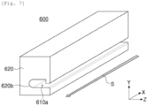
- the molding member 620 may be formed to extend to a predetermined length in one direction (for example, the X-axis direction of FIG. 6 ).
- the molded groove 610 may be configured to penetrate through the molding member 620 in one direction, and the sealing portion 10b of the battery cell 10 may be inserted into the molded groove 610 and bent while moving in a predetermined direction (for example, the arrow S direction in FIG. 6 ).
- the moldedgroove 610 continues continuously in one direction (for example, the X-axis direction of FIG. 6 ), and the cross-sectional shape of the molded groove 610 may be continuously changed in one direction (the X-axis direction of FIG. 6 ).
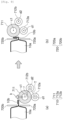
- FIG. 8 provides cross-sectional views of portions I-I', II-II', III-III', and IV-IV' in FIG. 6 , respectively.
- the molded groove 610 may be configured in different shapes in respective positions, and accordingly, the sealing portion 10b may be gradually bent corresponding to the shape of the molded groove 610 while passing through respective portions of the molded groove 610.
- the molded groove 610 may form an inlet 620a into which the sealing portion 10b may enter at one end of the molding member 620, and may form an outlet 620b through which the sealing portion may exit at the other end of the molding member 620.
- FIG. 6 illustrates the state of the inlet 620a formed in the molding member 620
- FIG. 7 illustrates the state of the outlet 620b formed in the molding member 620.
- the inlet 620a and the outlet 620b of the molding member 620 may have different shapes.
- the molded groove 610 forming the inlet 620a may have a shape bent at approximately 90 degrees, and the molded groove 610 is gradually changed in shape in one direction (X-axis direction in FIG.
- the sealing portion 10b entering the inlet 620a may be gradually bent corresponding to the shape change of the molded groove 610, and may exit the molding member in a folded state of approximately 180 degrees upon reaching the exit 620b.
- the molded groove 610 may include a first molded groove 610a having a shape open toward one side of the molding member 620, and a second molded groove 610b connected to the first molded groove 610a and inclined with respect to the first molded groove 610a.
- the first molded groove 610a may be configured as a groove parallel to the reference plane (for example, the X-Z plane in FIG. 6 ), and the second molded groove 610b may have a shape inclined with respect to the reference plane (or the first molded groove). Accordingly, a predetermined angle may be formed between the second molded groove 610b and the first molded groove 610a.
- the angle between the first molded groove 610a and the second molded groove 610b may vary continuously in one direction (for example, the S direction of FIG. 6 ).
- the second molded groove 610b of the molding member 620 may be formed in a continuous spiral shape in one direction (for example, the X-axis direction of FIG. 6 ) .
- the second molded groove 610b of the molding member 620 may be formed in a spiral shape in which a bent angle is continuously changed.
- the end of the second molded groove 610b in the I-I' portion of the molding member 620 is provided to be perpendicular to the ground (part (a) of FIG. 8 ), and in the II-II' part, the end of the second molded groove 610b may be formed in a state in which it rotates counterclockwise compared to the I-I' part ( FIG. 8(b) part).
- the end of the second molded groove 610b in the III-III' part of the molding member 620 may be formed in a state rotated counterclockwise compared to the II-II' part, and the end of the second molded groove 610b in the IV-IV' part may be formed in a state in which it rotates counterclockwise compared to the III-III' part.
- the sealing portion 10b of the battery cell 10 is relatively transferred in one direction (for example, the arrow S direction in FIGS. 6 and 7 ) while being inserted into the molded groove 610 of the molding member 620, and is folded corresponding to the shape of the molded groove 610 continuously formed in the transfer direction. Since the angle at which the molded groove 610 is bent is continuously changed in the longitudinal direction (for example, the X-axis direction in FIGS. 6 and 7 ) of the molding member 620, correspondingly, the sealing portion 10b of the battery cell 10 is also continuously folded in a shape corresponding thereto.
- the sealing portion 10b of the battery cell 10 is continuously folded while passing through the apparatus 600 for manufacturing a second battery cell, and may be folded by 180 degrees based on the direction in which the end of the sealing portion 10b faces before going through the apparatus for manufacturing a first battery cell.
- the molding member 620 is transferred in one direction (for example, the arrow S direction in FIGS. 6 and 7 ) to fold the sealing portion 10b of the battery cell 10.
- the battery cell 10 is transferred in one direction (for example, the arrow S direction in FIGS. 6 and 7 ), and the molding member 620 may be transferred in a direction opposite to the transfer direction of the battery cell 10 to fold the sealing portion 10b of the battery cell 10.
- the battery cell passing through the apparatus for manufacturing a second battery cell may enter an apparatus for manufacturing a third battery cell, and the apparatus for manufacturing a third battery cell may perform a second folding step (for example, S306 of FIG. 3 ).
- FIG. 9 is an illustrative view illustrating a state in which the sealing portion 10b of the battery cell 10 is folded by the apparatus for manufacturing a third battery cell according to embodiments.
- the apparatus for manufacturing a third battery cell may fold the sealing portion 10b of the battery cell 10 folded through the first and second battery cell manufacturing apparatuses described above with reference to FIGS. 4 to 8 .
- the apparatus for manufacturing a third battery cell may fold the sealing portion 10b of the battery cell 10 in the same direction as the folding direction in the first and second battery cell manufacturing apparatuses.
- the apparatus for manufacturing a third battery cell includes a support unit 720 supporting the sealing portion 10b of the battery cell 10, and a folding unit 710 folding the sealing portion 10b in a state supported by the support units 720.
- the support unit 720 of the apparatus for manufacturing a third battery cell may include at least two support members 720a and 720b.
- the support unit 720 may include a first support member 720a and a second support member 720b provided to face each other. At least a portion of the battery cell 10 may be fixed between the first support member 720a and the second support member 720b.
- the first support member 720a and the second support member 720b move in a direction to be closer to each other, and the boundary between the body portion 10a and the sealing portion 10b of the battery cell 10 may be inserted therebetween and supported.
- the 'boundary' is a portion extending from the body portion 10a to the sealing portion 10b, and may be a portion adjacent to the terrace of the body portion 10a. Accordingly, the body portion 10a may be located on any one side (that is, one side) and the sealing portion 10b may be located on another side (that is, the other side), with the support unit 720 in the middle. For example, as illustrated in FIG. 9 , one side of the support unit 720 may face the narrow side of the body portion 10a, and the sealing portion 10b extending from the body portion 10a passes through the first support member 720a and the second support member 720b and protrudes from the other side of the support unit 720 to be supported by the support unit 720.
- the folding unit 710 may press the sealing portion 10b to be bent, while moving along the other side of the support unit 720.
- the folding unit 710 is provided adjacent to the support unit 720, and may be slidably driven along the other side of the support unit 720 in one direction (for example, the arrow k direction in FIG. 9 ).
- the moving direction of the folding unit 710 may be a direction from the first support member 720a to the second support member 720b.
- the moving direction of the folding unit 710 may be a direction substantially parallel to one surface of the second support member 720b.
- the moving direction of the folding unit 710 is not limited to the description above, and the folding unit may move in any direction as long as it may contact the sealing portion and bend the sealing portion.
- the folding unit 710 may move along the other surface of the support unit 720. Accordingly, the folding unit 710 may push up and bend the sealing portion 10b of the battery cell 10 so as to be in close contact with the support unit 720.
- the folding unit 710 may include at least one roller 711, 712a, 712b.
- the folding unit 710 may include a pressure roller 711 for pushing and folding the sealing portion 10b of the battery cell 10, and auxiliary rollers 712a and 712b supporting the pressure roller 711.
- the length of the pressure roller 711 may be greater than or equal to the length of the battery cell 10 being folded. Accordingly, the pressure roller 711 may move to contact the overall sealing portion 10b of the battery cell 10 in the longitudinal direction.
- the pressure roller 711 may deviate from an original position or be bent due to the repulsive force received from the sealing portion 10b in the process in which the pressure roller 711 folds the sealing portion 10b.
- a long-width cell it may have a width of about 600 mm or more, and as the length of the long-width cell increases, a greater force is applied to the pressure roller 711 in the process of folding the sealing portion 10b.
- one or more auxiliary rollers 712a and 712b adjacent to the pressure roller 711 may be disposed to support the pressure roller 711.
- the auxiliary rollers 712a and 712b may be configured to move together with the pressure roller 711. That is, the auxiliary rollers 712a and 712b may move in the moving direction of the pressure roller (for example, the arrow k direction in FIG. 9 ) while maintaining contact with the pressure roller 711.
- the diameter of the auxiliary rollers 712a and 712b may be equal to or smaller than the diameter of the pressure roller 711.
- two auxiliary rollers 712a and 712b having a relatively small diameter may be disposed in contact with different portions of the pressure roller 711 having a relatively large diameter.
- a plurality of auxiliary rollers 712a and 712b may be provided adjacent to respective different positions of the pressure roller 711.
- the auxiliary rollers 712a and 712b may include a first auxiliary roller 712a and a second auxiliary roller 712b adjacent to different sides of the pressure roller 711. Accordingly, the first auxiliary roller 712a and the second auxiliary roller 712b may support the pressure roller 711 in different directions respectively.
- the pressure roller 711 and the auxiliary rollers 712a and 712b may be configured to be rotatable, respectively.
- a rotation shaft c1 of the pressure roller 711 and rotation axes d1 and d2 of the auxiliary rollers 712a and 712b may be substantially parallel to each other.
- virtual lines connecting the rotation center c1 of the pressure roller 711 and rotation centers d1 and d2 of the auxiliary rollers 712a and 712b may meet each other to form a triangle T.
- the triangle may be an isosceles triangle.
- a virtual line connecting the rotation center c1 of the pressure roller 711 and the rotation center d1 of the first auxiliary roller 712a, and a virtual line connecting the rotation center c1 of the pressure roller 711 and the rotation center d2 of the second auxiliary roller 712b may meet each other to form an acute angle. According to this structure, the repulsive force received from the sealing portion while the pressure roller 711 moves in one direction (arrow k direction in Fig. 9 ) is properly distributed to the two auxiliary rollers 712a and 712b and acts, thereby effectively supporting the pressure roller 711.
- the folding unit 710 moves in one direction (for example, the arrow k direction in FIG. 9 ) to push and fold the sealing portion 10b of the battery cell 10.
- the pressure roller 711 may move from a first position facing the first support member 720a to a second position facing the second support member 720b, and may press the sealing portion 10b in the process of moving.
- the sealing portion 10b pressed by the pressure roller 711 may be bent to come into contact with the second support member.
- the position of the pressure roller 711 in the folding unit 710 may be changed as needed. Accordingly, the pressure roller 711 may push the sealing portion 10b at various angles. For example, as illustrated in FIG. 9 , the position of the pressure roller 711 may be set so that the end of the sealing portion 10b is at a position spaced apart from the path in which the central axis c1 of the pressure roller 711 moves. In this case, the pressure roller 711 may be folded in contact with the sealing portion 10b in an oblique direction.
- the folding direction by the pressure roller 711 may be the same as the folding direction through the first and second battery cell manufacturing apparatuses described above with reference to FIGS. 4 to 8 .
- the apparatus for manufacturing a first battery cell of FIG. 4 or 5 at least a partial area of the sealing portion 10b of the battery cell 10 is folded counterclockwise by 90 degrees
- the apparatus for manufacturing a second battery cell of FIG. 6 at least a partial area folded in the apparatus for manufacturing a first battery cell is again folded by 90 degrees counterclockwise, and may be folded 180 degrees in a counterclockwise direction.
- the folded at least a partial area of the sealing portion 10b and the other area facing the at least partial area may be folded together in a counterclockwise direction by 90 degrees. Accordingly, by passing through the first to third battery cell manufacturing apparatuses, the at least a partial area of the battery cell 10 may be rotated counterclockwise by a total of 270 degrees to be folded adjacent to the body portion (10a of FIG. 1 ) of the battery cell 10.
- both the apparatus for manufacturing a third battery cell and the apparatus for manufacturing a first battery cell may fold the sealing portion 10b of the battery cell 10 by approximately 90 degrees
- both battery cell manufacturing apparatuses are interchangeable.
- the first folding step (for example, S304 in FIG. 3 ) may be performed by the apparatus for manufacturing a third battery cell described in FIG. 9 and the apparatus for manufacturing a second battery cell described in FIGS . 6 to 8 sequentially. That is, while the support unit 720 of the apparatus for manufacturing a third battery cell supports the battery cell 10, a portion of the first folding step (S304 of FIG. 3 ) may be performed as the pressure roller 711 of the apparatus for manufacturing a third battery cell pushes up the sealing portion 10b in one direction and folds the same by 90 degrees.
- FIG. 9 For a detailed description thereof, reference may be made to the description of FIG. 9 .
- the features of the present disclosure may be applied in whole or in part to an apparatus for manufacturing a battery cell.
Landscapes
- Chemical & Material Sciences (AREA)
- Chemical Kinetics & Catalysis (AREA)
- Electrochemistry (AREA)
- General Chemical & Material Sciences (AREA)
- Engineering & Computer Science (AREA)
- Manufacturing & Machinery (AREA)
- Sealing Battery Cases Or Jackets (AREA)
- Secondary Cells (AREA)
Abstract
Description
- The present disclosure relates to an apparatus for manufacturing a battery cell.
- Recently, a rechargeable battery capable of charging and discharging has been widely used as an energy source for wireless mobile devices. In addition, secondary batteries are attracting attention as a power source for electric vehicles (EVs), hybrid electric vehicles (HEVs) and the like, which are proposed as a way to solve air pollution issues, such as for gasoline, diesel vehicles and the like, using fossil fuels.
- On the other hand, the battery cell undergoes a process of folding the bonding portion (or the sealing portion) of the casing of the battery cell during the manufacturing process. Folding refers to bending or folding at least a portion of the sealing portion of the battery cell casing toward the body portion of the battery cell. Since the area of the sealing portion of the battery cell is very narrow compared to the size of the entire battery cell, it is difficult to fold in the desired position, and during the folding process, unnecessary pressure is applied to the electrode assembly or the sealing portion is destroyed, causing a problem in which a battery cell is defective.
- An aspect of the present disclosure is to increase efficiency and reliability of a manufacturing process of a battery cell. In addition, an aspect of the present disclosure is to enable a process of folding a casing material of a pouch-type battery cell to be stably performed.
- According to an aspect of the present disclosure, an apparatus for manufacturing a battery cell includes a body portion having rigidity; and a molded groove configured to allow at least a portion of the sealing portion of the battery cell to be inserted and passed therethrough. The molded groove penetrates the body portion in a first direction, and a shape of the molded groove is changed in the first direction.
- In embodiments, the molded groove may comprise an inlet disposed at one end of the body portion in the first direction and configured to allow the sealing portion to be inserted; and an outlet disposed at the other end in the first direction and configured to allow the sealing portion to exit.
- In embodiments, shapes of the inlet and the outlet may be different from each other.
- In embodiments, the molded groove may include a first molded groove open in a second direction, perpendicular to the first direction, at one side of the body portion; and a second molded groove connected to the first molded groove and inclined with respect to the first molded groove.
- In embodiments, an angle between the first molded groove and the second molded groove may be continuously changed in the first direction.
- In embodiments, the angle between the first molded groove and the second molded groove may gradually decrease in the first direction.
- In embodiments, an angle between the first molded groove and the second molded groove at an end of the body portion in the first direction may be perpendicular.
- In embodiments, the body portion may be movable in the first direction.
- According to an aspect of the present disclosure, an apparatus for manufacturing a battery cell includes a support unit configured to support a sealing portion of a battery cell, wherein one side of the support unit is configured to face a body portion in which an electrode assembly of the battery cell is accommodated; and a folding unit facing the other side opposite to the one side of the support unit and configured to bend the sealing portion of the battery cell. The folding unit is configured to be movable along the other side of the support unit to bend the sealing portion of the battery cell.
- In embodiments, the support unit may include a first support member and a second support member configured to be movable in different directions, and the first support member and the second support member are configured such that the sealing portion of the battery cell can be fixed therebetween.
- In embodiments, the first support member and the second support member may be configured to support a boundary between the body portion and the sealing portion.
- In embodiments, the folding unit may include a pressure roller configured to be movablefrom a first position facing the first support member to a second position facing the second support member, and the pressure roller may be configured to bend the sealing portion so that the sealing portion comes into contact with the second support member.
- In embodiments, the folding unit may further include an auxiliary roller supporting the pressure roller, and the auxiliary roller may be configured to move together in contact with the pressure roller.
- In embodiments, a diameter of the auxiliary roller may be equal to or less than a diameter of the pressure roller.
- In embodiments, the pressure roller and the auxiliary roller may be respectively rotatable, and an axis of rotation of the auxiliary roller may be parallel to an axis of rotation of the pressure roller.
- In embodiments, the auxiliary roller may include a first auxiliary roller and a second auxiliary roller in contact with different portions of the pressure roller, and an angle between a virtual line connecting a center of rotation of the pressure roller and a center of rotation of the first auxiliary roller and a virtual line connecting the center of rotation of the pressure roller and a center of rotation of the second auxiliary roller may be an acute angle.
- According to the apparatus for manufacturing a battery cell according to the embodiments, the sealing portion of the battery cell may be stably folded at a desired angle.
- In the apparatus for manufacturing a battery cell according to embodiments, by effectively folding a partial surface of the sealing portion of the battery cell, a phenomenon in which the sealing of the sealing portion is released may be prevented. In addition, as some surfaces of the sealing portion of the battery cell are folded, the volume of the electrode assembly disposed in the inner space of the module housing having the same size may be increased.
-
-
FIG. 1 illustrates a pouch-type battery cell. -
FIG. 2 illustrates a process in which a sealing portion of a battery cell is deformed according to a folding process according to embodiments. -
FIG. 3 is a flowchart of a folding process according to example embodiments. -
FIG. 4 is an illustrative view illustrating a state in which a sealing portion of a battery cell is folded by an apparatus for manufacturing a first battery cell according to embodiments. -
FIG. 5 is an illustrative view illustrating a state in which a sealing portion of a battery cell is folded by the apparatus for manufacturing a first battery cell according to the embodiment. -
FIG. 6 is a perspective view of an apparatus for manufacturing a second battery cell according to example embodiments. -
FIG. 7 is a perspective view of an apparatus for manufacturing a second battery cell according to an embodiment, as viewed from an angle different from that ofFIG. 6 . -
FIG. 8 is an illustrative view illustrating a state in which a sealing portion of a battery cell is folded by the apparatus for manufacturing a second battery cell according to embodiments. -
FIG. 9 is an illustrative view illustrating a state in which a sealing portion of a battery cell is folded by an apparatus for manufacturing a third battery cell according to an embodiment. - The terms or words used in the present specification and claims described below should not be construed as being limited to conventional or dictionary meanings, and based on the principle that an inventor may appropriately define the concept of a term in order to best describe his invention, it should be interpreted as meaning and concept consistent with the technical spirit of the present disclosure. Therefore, the configurations illustrated in the embodiments and drawings described in this specification are only the most preferred embodiments of the present disclosure, and do not represent all of the technical spirit of the present disclosure, and it should be understood that various equivalents and modifications may be substituted for them at the time of filing.
- Hereinafter, preferred embodiments of the present disclosure will be described with reference to the accompanying drawings. However, the embodiment of the present disclosure may be modified in various other forms, and the scope of the present disclosure is not limited to the embodiments described below. In addition, the embodiments of the present disclosure are provided in order to more completely explain the present disclosure to those of ordinary skill in the art. The shapes and sizes of elements in the drawings may be exaggerated for clearer explanation.
- Also, in this specification, the singular expression includes the plural expression unless the context clearly dictates otherwise. Throughout the specification, the same reference signs refer to the same elements or corresponding elements.
- In addition, in the present specification, expressions such as upper side, upper portion, lower side, lower portion, side surface, front side, back side, and the like are expressed based on the direction illustrated in the drawings, and if the direction of the corresponding object is changed, it may be expressed differently.
- In addition, terms including an ordinal number, such as "first", "second", etc. used herein may be used to describe various elements, but the elements are not limited by the terms, and the above terms are used only for the purpose of distinguishing one component from another. For example, without departing from the scope of the present disclosure, a first component may be referred to as a second component, and similarly, a second component may also be referred to as a first component.
-
FIG. 1 illustrates abattery cell 10.FIG. 2 illustrates a process in which a sealingportion 10b of thebattery cell 10 is deformed according to the folding process according to the embodiments. Hereinafter, a folding process of thebattery cell 10 will be described with reference toFIGS. 1 to 2 . - First, referring to
FIG. 1 , thebattery cell 10 may be a pouch-type battery cell. Thebattery cell 10 includes anelectrode assembly 11 and a casing 12 (or a pouch) surrounding theelectrode assembly 11. Theelectrode assembly 11 is provided in a form in which positive and negative plates are sequentially stacked, and may further include a separator between the positive and negative plates. - The
casing 12 is provided in the form of enclosing theelectrode assembly 11 to configure the exterior of thebattery cell 10, and may protect theelectrode assembly 11 from external impact. In addition, thecasing 12 may seal theelectrode assembly 11 from the outside. Thebattery cell 10 includes anelectrode tab 13 extending in a longitudinal direction, and theelectrode tab 13 is connected to an electrode plate (a positive electrode plate or a negative electrode plate) of theelectrode assembly 11. - The
casing 12 may be provided in the form of sandwiching theelectrode assembly 11 from both sides. For example, thecasing 12 may include afirst casing 12a enclosing an upper portion of theelectrode assembly 11 and asecond casing 12b enclosing a lower portion of theelectrode assembly 11. The inner portion of thecasing 12 surrounds theelectrode assembly 11, and the peripheral portion may be bonded to a peripheral portion of theopposite casing 12. For example, thefirst casing 12a and thesecond casing 12b are bonded to each other at the edge portion. In this case, thefirst casing 12a and thesecond casing 12b may be provided as asingle casing 12. That is, onecasing 12 surrounds theelectrode assembly 11 over the top and bottom, and may be bonded on the periphery of the other side portions (for example, the right long side and two short sides of thebattery cell 10 ofFIG. 1 ) except for one side (for example, the left long side of thebattery cell 10 inFIG. 1 ) of theelectrode assembly 11, to seal theelectrode assembly 11 from the outside. - In embodiments, the
battery cell 10 may include abody portion 10a and a sealingportion 10b. Thebody portion 10a accommodates theelectrode assembly 11 and means a portion having a thickness corresponding to theelectrode assembly 11. A cross-section of thebody portion 10a may include theelectrode assembly 11 and thecasing 12 covering both sides of theelectrode assembly 11. The sealingportion 10b may mean a thin portion extending from at least one edge of thebody portion 10a in the longitudinal direction (or in a direction perpendicular to the stacking direction). For example, the sealingportion 10b may be a portion in which the casing is overlapped and joined when one sheet of the casing is folded. Accordingly, the cross-section of the sealingportion 10b may be composed of two layers of casing. - Referring to
FIG. 2 , the sealingportion 10b of thebattery cell 10 may be gradually folded through a plurality of folding processes. In this case, the respective folding processes may be performed by one folding process unit or sequentially by individual folding process units . As illustrated inFIG. 2 , the sealingportion 10b of thebattery cell 10 is folded one or more times through a plurality of folding processes, and for example, is folded about 90 degrees in a first folding process, and may be folded again by 90 degrees in a second folding process, to be in a folded state by 180 degrees. In addition, in a third folding process, it may be additionally folded by 90 degrees. Finally, the sealingportion 10b may be positioned adjacent to the side wall (14 ofFIG. 1 ) of thebody portion 10a. - On the other hand, the sealing
portion 10b illustrated inFIG. 2 means a portion in which theelectrode tab 13 is not located, from among portions remaining after wrapping theelectrode assembly 11 among the casing 12 of thebattery cell 10 ofFIG. 1 . That is, the sealingportion 10b ofFIG. 2 may correspond to the upper part of thebattery cell 10 among the extra parts remaining after thecasing 12 of thebattery cell 10 ofFIG. 1 surrounds theelectrode assembly 11. However, this is an example, and when a sealing portion is formed on four surfaces by overlapping two sheets of thecasing 12, a process of folding the upper portion and the lower portion where the electrode tab 130 is not located may be performed several times. The sealingportion 10b described in the followingFIGS. 3 to 7 corresponds to the sealingportion 10b ofFIG. 2 , and overlapping descriptions will be omitted. - In addition, although the folding process is illustrated in
FIG. 2 as going through four steps, this is only an example, and the folding process may include two, three, or five or more folding processes. - Referring to
FIG. 3 , a folding process according to embodiments will be described in more detail. The battery cell and constituent portions thereof described inFIG. 3 correspond to the battery cell and the constituent portions described inFIGS. 1 and2 , and overlapping descriptions will be omitted. - Prior to folding the sealing portion (for example, 10b of
FIG. 1 ) of the battery cell (for example, 10 inFIG. 1 ), the positions of the battery cells are aligned in an alignment step (S301) . That is, in the alignment step, in order to accurately fold the sealing portion in a desired position, the battery cell is positioned appropriately. - After positioning the battery cell properly, a cutting step (S302) of cutting to a predetermined length is performed so that the sealing portion of the battery cell may be folded by a specified length.
- Before the folding process proceeds, a PFL (Pre Forming Location) step (S303) of pre-forming the corresponding folding line to prevent meandering during folding is performed.
- The sealing portion of the battery cell that has undergone the PFL step S303 is folded at least once in a first folding step S304 so that the end of the sealing portion faces the sidewall of the body portion of the battery cell. That is, in the first folding step (S304), the sealing portion is folded by 180 degrees (refer to the third figure of
FIG. 2 ). - A first pressing step (S305) is performed by pressing the sealing portion folded by 180 degrees with heat and pressure. Heat and pressure are applied to the folded part to maintain the folded shape.
- The folded sealing portion is folded at least once again in a second folding step (S306) so that the sealing portion faces in the width direction of the battery cell. That is, in the second folding step (S306), the sealing portion is folded by 90 degrees in the same direction as the folded direction in the first folding step (refer to the fourth figure in
FIG. 2 ). - Thereafter, the folded sealing portion is pressed and molded by heat and pressure. Heat and pressure are applied to the folded part to maintain the folded shape.
- In a sizing step (S308), the folded sealing portion is passed through a sizing roller to form the sealing portion adjacent to the sidewall of the body portion of the battery cell. Accordingly, the folded sealing portion is adjacent to the sidewall of the body portion of the battery cell at an acute angle.
- However, in the folding process of the embodiments, at least a portion of the various processes described in
FIG. 3 may be omitted or additionally added. In addition, the order of the various processes described inFIG. 3 is not limited to the illustration, and any two or more processes may be performed at the same time or in a different order. - Hereinafter, an apparatus for manufacturing a battery cell according to embodiments in which at least a portion of the folding processes described with reference to
FIG. 3 is performed will be described in detail. - In embodiments, the first folding step (for example, S304 of
FIG. 3 ) of folding the sealing portion by 180 degrees may be performed by an apparatus for manufacturing a first battery cell described inFIG. 4 orFIG. 5 and an apparatus for manufacturing a second battery cell described inFIGS. 5 to 8 . For example, the sealing portion may be first folded by 90 degrees by the apparatus for manufacturing a first battery cell and then further folded by 90 degrees by the apparatus for manufacturing a second battery cell, to be folded by a total of 180 degrees. - First, with reference to
FIG. 4 , an apparatus for manufacturing a first battery cell will be described, in which at least a portion of the first folding step (for example, S304 ofFIG. 3 ) may be performed. - The apparatus for manufacturing a first battery cell folds the sealing
portion 10b of thebattery cell 10. For example, as sequentially illustrated inFIGS. 4A to 4D , the apparatus for manufacturing a first battery cell continuously folds the sealingportion 10b of thebattery cell 10 such that the end of the sealingportion 10b of thebattery cell 10 faces thebody portion 10a of thebattery cell 10. That is, the sealingportion 10b of thebattery cell 10 may be folded by 90 degrees by the apparatus for manufacturing a first battery cell. - In embodiments, the apparatus for manufacturing a first battery cell may include a plurality of
folding units folding units FIGS. 4A, 4B, 4C, and 4D , thefolding units first folding unit 410, asecond folding unit 420, athird folding unit 430, and afourth folding unit 440, which gradually bend the sealingportion 10b. Thefolding units battery cell 10 to bend the sealingportion 10b of the battery cell at various angles. - In embodiments, one folding unit (for example, 410) may include at least two rollers (for example, 411 and 412) . For example, as illustrated in
FIG. 4 , thefirst folding unit 410 may include afirst roller 411 and asecond roller 412 having rotation axes a1 and b1 parallel to each other. The sealingportion 10b of thebattery cell 10 may pass between thefirst roller 411 and thesecond roller 412 while being in contact with the roller surfaces of thefirst roller 411 and thesecond roller 412. The distance between the tworollers battery cell 10 to be folded by the apparatus for manufacturing a first battery cell. For example, when the thickness of the casing of thebattery cell 10 is about 270 µm, the tworollers rollers - In embodiments, in the apparatus for manufacturing a first battery cell, the plurality of
folding units folding units battery cell 10 at installation angles thereof changed sequentially. For example, thefirst folding unit 410 installed first on the inlet side of the apparatus for manufacturing a first battery cell may includerollers second folding unit 420 installed to be spaced apart from the first folding unit in the transport direction of thebattery cell 10 includesrollers third folding unit 430 installed on the rear of thesecond folding unit 420 may includerollers battery cell 10, and thefourth folding unit 440 finally installed on the outlet side of the apparatus for manufacturing a first battery cell may includerollers - In embodiments, the rollers included in each of the
folding units folding units battery cell 10 to approach thebody portion 10a of thebattery cell 10, and may thus be configured to have a gradually smaller size in order to prevent interference with thebody portion 10a. That is, as illustrated inFIG. 4 , the size of thesecond roller 442 included in thefourth folding unit 440 may be smaller than the size of thesecond roller 412 included in thefirst folding unit 410. However, the sizes of the rollers included in thefolding units battery cell 10. -
FIG. 4 illustrates a total of fourfolding units folding units folding units - The
battery cell 10 transferred to the apparatus for manufacturing a first battery cell is inserted between thefirst roller 411 and thesecond roller 412 of thefirst folding unit 410 in which the sealingportion 10b is provided on the inlet side of the apparatus for manufacturing a first battery cell. The sealingportion 10b passes through therespective rollers folding units folding units portion 10b of thebattery cell 10 enters thefirst folding unit 410 provided on the inlet side of the apparatus for manufacturing a first battery cell, in a state oriented in a direction parallel to the ground, and is sequentially folded by the plurality offolding units battery cell 10, and is therefore folded at an angle (for example, 90 degrees) corresponding to the angle at which thefourth folding unit 440 provided on the outlet side of the apparatus for manufacturing a first battery cell is installed. - Hereinafter, an apparatus for manufacturing a first battery cell according to other embodiments will be described with reference to
FIG. 5. FIG. 5 is an illustrative view illustrating a state in which a sealing portion of a battery cell is folded by an apparatus for manufacturing a first battery cell according to embodiments. - In embodiments, the apparatus for manufacturing a first battery cell may include a plurality of
folding units portion 10b of abattery cell 10. - The plurality of
folding units battery cell 10 sequentially passes through the plurality offolding units portion 10b may be gradually bent at a larger angle. For example, as illustrated inFIG. 5 , the sealingportion 10b of thebattery cell 10 enters the first folding unit 510 (part (a) ofFIG. 5 ), and may then be slightly bent in the process of passing through the second folding unit 520 positioned on the rear of thefirst folding unit 510. The sealingportion 10b exiting the second folding unit 520 after (part (b) ofFIG. 5 ) may be bent at a larger angle in thethird folding unit 530. (Part (c) ofFIG. 5 ) The sealingportion 10b exiting thethird folding unit 530 may be bent at 90 degrees compared to the shape of the initial shape of the sealingportion 10b in thefourth folding unit 540. (Part (d) ofFIG. 5 ) - Each of the
folding units FIG. 5 , thefirst folding unit 510 may include a first roller 511 and asecond roller 512 with roller surfaces facing each other. The first roller 511 and thesecond roller 512 may be rotatable, and the respective rotation axes a1 and b1 may be disposed to be approximately parallel to each other. - The
first rollers second rollers FIG. 5 , thesecond rollers portion 10b of thebattery cell 10. Thefirst rollers portion 10b based on the bending point set by thesecond rollers - In embodiments, the inclination of the roller surfaces of the
first rollers folding units portion 10b in contact with the roller surfaces may also be bent at a gradually wide angle. - In embodiments, the roller surfaces of the
first rollers first rollers first regions second rollers second regions portion 10b. - Although not illustrated in the drawing, the
first regions first rollers second rollers portion 10b. For example, on the outer peripheral surfaces of thesecond roller first rollers portion 10b. A guide groove (not illustrated) corresponding to a shape of the guide protrusion (not illustrated) may be disposed in thefirst regions first rollers portion 10b in contact with thesecond regions first rollers second regions first rollers portion 10b, the bent position may always be kept constant. - The plurality of folding units included in the apparatus for manufacturing a first battery cell illustrated in
FIG. 5 may be configured with rollers whose rotational axis is parallel to a reference plane (for example, the ground). With this structure, the sealing portion may be folded at a stable angle while the roller arrangement structure is simple. In addition, the installation of the folding units may be easier, and the overall size of the manufacturing apparatus may be kept small. - The
battery cell 10 in which the sealingportion 10b is folded by the apparatus for manufacturing a first battery cell may be transferred to an apparatus for manufacturing a second battery cell. - Hereinafter, an
apparatus 600 for manufacturing asecond battery cell 600 will be described with reference toFIGS. 6 to 8 . Theapparatus 600 for manufacturing a second battery cell may fold the sealingportion 10b of thebattery cell 10 by 180 degrees. In embodiments, theapparatus 600 for manufacturing a second battery cell may fold the sealingportion 10b of thebattery cell 10 in the same direction as the folding direction in the apparatus for manufacturing a first battery cell. - The
apparatus 600 for manufacturing a second battery cell may include a molding member (mold body portion 620) for folding, and a moldedgroove 610 formed in the molding member. Themolding member 620 may be formed to extend to a predetermined length in one direction (for example, the X-axis direction ofFIG. 6 ). The moldedgroove 610 may be configured to penetrate through themolding member 620 in one direction, and the sealingportion 10b of thebattery cell 10 may be inserted into the moldedgroove 610 and bent while moving in a predetermined direction (for example, the arrow S direction inFIG. 6 ). - In embodiments, the
moldedgroove 610 continues continuously in one direction (for example, the X-axis direction ofFIG. 6 ), and the cross-sectional shape of the moldedgroove 610 may be continuously changed in one direction (the X-axis direction ofFIG. 6 ).FIG. 8 provides cross-sectional views of portions I-I', II-II', III-III', and IV-IV' inFIG. 6 , respectively. As illustrated inFIG. 8 , the moldedgroove 610 may be configured in different shapes in respective positions, and accordingly, the sealingportion 10b may be gradually bent corresponding to the shape of the moldedgroove 610 while passing through respective portions of the moldedgroove 610. - In embodiments, the molded
groove 610 may form aninlet 620a into which the sealingportion 10b may enter at one end of themolding member 620, and may form anoutlet 620b through which the sealing portion may exit at the other end of themolding member 620. For example,FIG. 6 illustrates the state of theinlet 620a formed in themolding member 620, andFIG. 7 illustrates the state of theoutlet 620b formed in themolding member 620. As illustrated in the drawing, theinlet 620a and theoutlet 620b of themolding member 620 may have different shapes. For example, the moldedgroove 610 forming theinlet 620a may have a shape bent at approximately 90 degrees, and the moldedgroove 610 is gradually changed in shape in one direction (X-axis direction inFIG. 6 ), and may be configured in a shape in which bent portions are combined into one at theoutlet 620b. According to the shape of the moldedgroove 610, the sealingportion 10b entering theinlet 620a may be gradually bent corresponding to the shape change of the moldedgroove 610, and may exit the molding member in a folded state of approximately 180 degrees upon reaching theexit 620b. - In embodiments, the molded
groove 610 may include a first moldedgroove 610a having a shape open toward one side of themolding member 620, and a second moldedgroove 610b connected to the first moldedgroove 610a and inclined with respect to the first moldedgroove 610a. - In embodiments, the first molded
groove 610a may be configured as a groove parallel to the reference plane (for example, the X-Z plane inFIG. 6 ), and the second moldedgroove 610b may have a shape inclined with respect to the reference plane (or the first molded groove). Accordingly, a predetermined angle may be formed between the second moldedgroove 610b and the first moldedgroove 610a. - In embodiments, the angle between the first molded
groove 610a and the second moldedgroove 610b may vary continuously in one direction (for example, the S direction ofFIG. 6 ). - In embodiments, the second molded
groove 610b of themolding member 620 may be formed in a continuous spiral shape in one direction (for example, the X-axis direction ofFIG. 6 ) . For example, as illustrated inFIG. 8 , the second moldedgroove 610b of themolding member 620 may be formed in a spiral shape in which a bent angle is continuously changed. The end of the second moldedgroove 610b in the I-I' portion of themolding member 620 is provided to be perpendicular to the ground (part (a) ofFIG. 8 ), and in the II-II' part, the end of the second moldedgroove 610b may be formed in a state in which it rotates counterclockwise compared to the I-I' part (FIG. 8(b) part). The end of the second moldedgroove 610b in the III-III' part of themolding member 620 may be formed in a state rotated counterclockwise compared to the II-II' part, and the end of the second moldedgroove 610b in the IV-IV' part may be formed in a state in which it rotates counterclockwise compared to the III-III' part. - In embodiments, the sealing
portion 10b of thebattery cell 10 is relatively transferred in one direction (for example, the arrow S direction inFIGS. 6 and7 ) while being inserted into the moldedgroove 610 of themolding member 620, and is folded corresponding to the shape of the moldedgroove 610 continuously formed in the transfer direction. Since the angle at which the moldedgroove 610 is bent is continuously changed in the longitudinal direction (for example, the X-axis direction inFIGS. 6 and7 ) of themolding member 620, correspondingly, the sealingportion 10b of thebattery cell 10 is also continuously folded in a shape corresponding thereto. For example, the sealingportion 10b of thebattery cell 10 is continuously folded while passing through theapparatus 600 for manufacturing a second battery cell, and may be folded by 180 degrees based on the direction in which the end of the sealingportion 10b faces before going through the apparatus for manufacturing a first battery cell. - In embodiments, while the position of the
battery cell 10 is fixed, themolding member 620 is transferred in one direction (for example, the arrow S direction inFIGS. 6 and7 ) to fold the sealingportion 10b of thebattery cell 10. In addition, thebattery cell 10 is transferred in one direction (for example, the arrow S direction inFIGS. 6 and7 ), and themolding member 620 may be transferred in a direction opposite to the transfer direction of thebattery cell 10 to fold the sealingportion 10b of thebattery cell 10. - The battery cell passing through the apparatus for manufacturing a second battery cell may enter an apparatus for manufacturing a third battery cell, and the apparatus for manufacturing a third battery cell may perform a second folding step (for example, S306 of
FIG. 3 ). - Hereinafter, the apparatus for manufacturing a third battery cell will be described with reference to
FIG. 9. FIG. 9 is an illustrative view illustrating a state in which the sealingportion 10b of thebattery cell 10 is folded by the apparatus for manufacturing a third battery cell according to embodiments. - The apparatus for manufacturing a third battery cell may fold the sealing
portion 10b of thebattery cell 10 folded through the first and second battery cell manufacturing apparatuses described above with reference toFIGS. 4 to 8 . In embodiments, the apparatus for manufacturing a third battery cell may fold the sealingportion 10b of thebattery cell 10 in the same direction as the folding direction in the first and second battery cell manufacturing apparatuses. - The apparatus for manufacturing a third battery cell includes a
support unit 720 supporting the sealingportion 10b of thebattery cell 10, and afolding unit 710 folding the sealingportion 10b in a state supported by thesupport units 720. - In embodiments, the
support unit 720 of the apparatus for manufacturing a third battery cell may include at least twosupport members FIG. 9 , thesupport unit 720 may include afirst support member 720a and asecond support member 720b provided to face each other. At least a portion of thebattery cell 10 may be fixed between thefirst support member 720a and thesecond support member 720b. For example, thefirst support member 720a and thesecond support member 720b move in a direction to be closer to each other, and the boundary between thebody portion 10a and the sealingportion 10b of thebattery cell 10 may be inserted therebetween and supported. Here, the 'boundary' is a portion extending from thebody portion 10a to the sealingportion 10b, and may be a portion adjacent to the terrace of thebody portion 10a. Accordingly, thebody portion 10a may be located on any one side (that is, one side) and the sealingportion 10b may be located on another side (that is, the other side), with thesupport unit 720 in the middle. For example, as illustrated inFIG. 9 , one side of thesupport unit 720 may face the narrow side of thebody portion 10a, and the sealingportion 10b extending from thebody portion 10a passes through thefirst support member 720a and thesecond support member 720b and protrudes from the other side of thesupport unit 720 to be supported by thesupport unit 720. - In embodiments, the
folding unit 710 may press the sealingportion 10b to be bent, while moving along the other side of thesupport unit 720. Thefolding unit 710 is provided adjacent to thesupport unit 720, and may be slidably driven along the other side of thesupport unit 720 in one direction (for example, the arrow k direction inFIG. 9 ). The moving direction of thefolding unit 710 may be a direction from thefirst support member 720a to thesecond support member 720b. Alternatively, the moving direction of thefolding unit 710 may be a direction substantially parallel to one surface of thesecond support member 720b. However, the moving direction of thefolding unit 710 is not limited to the description above, and the folding unit may move in any direction as long as it may contact the sealing portion and bend the sealing portion. - In embodiments, when one surface of the
support unit 720 faces the body portion of the battery cell, thefolding unit 710 may move along the other surface of thesupport unit 720. Accordingly, thefolding unit 710 may push up and bend the sealingportion 10b of thebattery cell 10 so as to be in close contact with thesupport unit 720. - The
folding unit 710 may include at least oneroller folding unit 710 may include apressure roller 711 for pushing and folding the sealingportion 10b of thebattery cell 10, andauxiliary rollers pressure roller 711. - In embodiments, the length of the
pressure roller 711 may be greater than or equal to the length of thebattery cell 10 being folded. Accordingly, thepressure roller 711 may move to contact theoverall sealing portion 10b of thebattery cell 10 in the longitudinal direction. - There is a risk that the
pressure roller 711 may deviate from an original position or be bent due to the repulsive force received from the sealingportion 10b in the process in which thepressure roller 711 folds the sealingportion 10b. For example, in the case of a long-width cell, it may have a width of about 600 mm or more, and as the length of the long-width cell increases, a greater force is applied to thepressure roller 711 in the process of folding the sealingportion 10b. To prevent this, in embodiments, one or moreauxiliary rollers pressure roller 711 may be disposed to support thepressure roller 711. - The
auxiliary rollers pressure roller 711. That is, theauxiliary rollers FIG. 9 ) while maintaining contact with thepressure roller 711. - In embodiments, the diameter of the
auxiliary rollers pressure roller 711. For example, as illustrated inFIG. 9 , twoauxiliary rollers pressure roller 711 having a relatively large diameter. - In embodiments, in order to stably support the
pressure roller 711, a plurality ofauxiliary rollers pressure roller 711. For example, as illustrated inFIG. 9 , theauxiliary rollers auxiliary roller 712a and a secondauxiliary roller 712b adjacent to different sides of thepressure roller 711. Accordingly, the firstauxiliary roller 712a and the secondauxiliary roller 712b may support thepressure roller 711 in different directions respectively. - In embodiments, the
pressure roller 711 and theauxiliary rollers pressure roller 711 and rotation axes d1 and d2 of theauxiliary rollers - In embodiments, virtual lines connecting the rotation center c1 of the
pressure roller 711 and rotation centers d1 and d2 of theauxiliary rollers - In embodiments, a virtual line connecting the rotation center c1 of the
pressure roller 711 and the rotation center d1 of the firstauxiliary roller 712a, and a virtual line connecting the rotation center c1 of thepressure roller 711 and the rotation center d2 of the secondauxiliary roller 712b may meet each other to form an acute angle. According to this structure, the repulsive force received from the sealing portion while thepressure roller 711 moves in one direction (arrow k direction inFig. 9 ) is properly distributed to the twoauxiliary rollers pressure roller 711. - In embodiments, in a state in which the
battery cell 10 is fixed by thesupport unit 720, thefolding unit 710 moves in one direction (for example, the arrow k direction inFIG. 9 ) to push and fold the sealingportion 10b of thebattery cell 10. For example, as illustrated inFIG. 9 , thepressure roller 711 may move from a first position facing thefirst support member 720a to a second position facing thesecond support member 720b, and may press the sealingportion 10b in the process of moving. The sealingportion 10b pressed by thepressure roller 711 may be bent to come into contact with the second support member. - In embodiments, the position of the
pressure roller 711 in thefolding unit 710 may be changed as needed. Accordingly, thepressure roller 711 may push the sealingportion 10b at various angles. For example, as illustrated inFIG. 9 , the position of thepressure roller 711 may be set so that the end of the sealingportion 10b is at a position spaced apart from the path in which the central axis c1 of thepressure roller 711 moves. In this case, thepressure roller 711 may be folded in contact with the sealingportion 10b in an oblique direction. - In embodiments, the folding direction by the
pressure roller 711 may be the same as the folding direction through the first and second battery cell manufacturing apparatuses described above with reference toFIGS. 4 to 8 . For example, in the apparatus for manufacturing a first battery cell ofFIG. 4 or5 , at least a partial area of the sealingportion 10b of thebattery cell 10 is folded counterclockwise by 90 degrees, and in the apparatus for manufacturing a second battery cell ofFIG. 6 , at least a partial area folded in the apparatus for manufacturing a first battery cell is again folded by 90 degrees counterclockwise, and may be folded 180 degrees in a counterclockwise direction. Thereafter, in the apparatus for manufacturing a third battery cell ofFIG. 9 , the folded at least a partial area of the sealingportion 10b and the other area facing the at least partial area may be folded together in a counterclockwise direction by 90 degrees. Accordingly, by passing through the first to third battery cell manufacturing apparatuses, the at least a partial area of thebattery cell 10 may be rotated counterclockwise by a total of 270 degrees to be folded adjacent to the body portion (10a ofFIG. 1 ) of thebattery cell 10. - Since both the apparatus for manufacturing a third battery cell and the apparatus for manufacturing a first battery cell may fold the sealing
portion 10b of thebattery cell 10 by approximately 90 degrees, both battery cell manufacturing apparatuses are interchangeable. For example, in embodiments, the first folding step (for example, S304 inFIG. 3 ) may be performed by the apparatus for manufacturing a third battery cell described inFIG. 9 and the apparatus for manufacturing a second battery cell described inFIGS . 6 to 8 sequentially. That is, while thesupport unit 720 of the apparatus for manufacturing a third battery cell supports thebattery cell 10, a portion of the first folding step (S304 ofFIG. 3 ) may be performed as thepressure roller 711 of the apparatus for manufacturing a third battery cell pushes up the sealingportion 10b in one direction and folds the same by 90 degrees. For a detailed description thereof, reference may be made to the description ofFIG. 9 . - In the above, the configuration and features of the present disclosure have been described based on the embodiments according to the present disclosure, but the present disclosure is not limited thereto. It is apparent to those skilled in the art that various changes or modifications may be made within the spirit and scope of the present disclosure, and accordingly, it is disclosed that such changes or modifications fall within the scope of the appended claims.
- Various modifications and variations of the present disclosure will be possible without departing from the essential characteristics of the present disclosure by those skilled in the art to which the present disclosure pertains.
- Therefore, the embodiments disclosed in the present disclosure are not intended to limit the technical spirit of the present disclosure, but to explain, and the scope of the technical spirit of the present disclosure is not limited by these embodiments.
- The protection scope of the present disclosure should be interpreted by the claims, and all technical ideas within the scope equivalent thereto should be interpreted as being included in the scope of the present disclosure.
- As described above, the features of the present disclosure may be applied in whole or in part to an apparatus for manufacturing a battery cell.
-
- 10:
- battery cell
- 10a:
- body portion
- 10b:
- sealing portion
- 600:
- apparatus for manufacturing a second battery cell
- 610:
- molded groove
- 620:
- molding member (mold body portion)
- 710:
- folding unit
- 711:
- pressure roller
- *119712a, 712b:
- auxiliary roller
- 720:
- support unit
Claims (16)
- An apparatus for manufacturing a battery cell, comprising:a body portion having rigidity; anda molded groove configured to allow at least a portion of the sealing portion of the battery cell to be inserted and passed therethrough,wherein the molded groove penetrates the body portion in a first direction, anda shape of the molded groove is changed in the first direction.
- The apparatus for manufacturing a battery cell of claim 1, wherein the molded groove comprises:an inlet disposed at one end of the body portion in the first direction and configured to allow the sealing portion to be inserted; andan outlet disposed at the other end in the first direction and configured to allow the sealing portion to exit.
- The apparatus for manufacturing a battery cell of claim 2, wherein shapes of the inlet and the outlet are different from each other.
- The apparatus for manufacturing a battery cell of claim 1, wherein the molded groove includes,a first molded groove open in a second direction, perpendicular to the first direction, at one side of the body portion; anda second molded groove connected to the first molded groove and inclined with respect to the first molded groove.
- The apparatus for manufacturing a battery cell of claim 4, wherein an angle between the first molded groove and the second molded groove is continuously changed in the first direction.
- The apparatus for manufacturing a battery cell of claim 5, wherein the angle between the first molded groove and the second molded groove gradually decreases in the first direction.
- The apparatus for manufacturing a battery cell of claim 5, wherein an angle between the first molded groove and the second molded groove at an end of the body portion in the first direction is perpendicular.
- The apparatus for manufacturing a battery cell of claim 1, wherein the body portion is configured to be movable in the first direction.
- An apparatus for manufacturing a battery cell, comprising:a support unit configured to support a sealing portion of a battery cell, wherein one side of the support unit is configured to face a body portion in which an electrode assembly of the battery cell is accommodated; anda folding unit facing the other side opposite to the one side of the support unit and configured to bend the sealing portion of the battery cell,wherein the folding unit is configured to be movable along the other side of the support unit to bend the sealing portion of the battery cell.
- The apparatus for manufacturing a battery cell of claim 9, wherein the support unit includes a first support member and a second support member configured to be movable in different directions,
wherein the first support member and the second support member are configured such that the sealing portion of the battery cell can be fixed therebetween. - The apparatus for manufacturing a battery cell of claim 10, wherein the first support member and the second support member are configured to support a boundary between the body portion and the sealing portion.
- The apparatus for manufacturing a battery cell of claim 10, wherein the folding unit includes a pressure roller configured to be movable from a first position facing the first support member to a second position facing the second support member,
wherein the pressure roller is configured to bend the sealing portion so that the sealing portion comes into contact with the second support member. - The apparatus for manufacturing a battery cell of claim 12, wherein the folding unit further includes an auxiliary roller supporting the pressure roller,
wherein the auxiliary roller is configured to move together in contact with the pressure roller. - The apparatus for manufacturing a battery cell of claim 13, wherein a diameter of the auxiliary roller is equal to or less than a diameter of the pressure roller.
- The apparatus for manufacturing a battery cell of claim 13, wherein the pressure roller and the auxiliary roller are respectively rotatable, and
an axis of rotation of the auxiliary roller is parallel to an axis of rotation of the pressure roller. - The apparatus for manufacturing a battery cell of claim 15, wherein the auxiliary roller includes a first auxiliary roller and a second auxiliary roller in contact with different portions of the pressure roller, and
wherein an angle between a virtual line connecting a center of rotation of the pressure roller and a center of rotation of the first auxiliary roller and a virtual line connecting the center of rotation of the pressure roller and a center of rotation of the second auxiliary roller is an acute angle.
Applications Claiming Priority (3)
| Application Number | Priority Date | Filing Date | Title |
|---|---|---|---|
| KR20210031423 | 2021-03-10 | ||
| KR1020220025119A KR20220127146A (en) | 2021-03-10 | 2022-02-25 | Apparatus for Manufacturing Battery Cell |
| PCT/KR2022/003388 WO2022191646A1 (en) | 2021-03-10 | 2022-03-10 | Battery cell manufacturing device |
Publications (2)
| Publication Number | Publication Date |
|---|---|
| EP4306300A1 true EP4306300A1 (en) | 2024-01-17 |
| EP4306300A4 EP4306300A4 (en) | 2025-03-12 |
Family
ID=83228172
Family Applications (1)
| Application Number | Title | Priority Date | Filing Date |
|---|---|---|---|
| EP22767542.8A Pending EP4306300A4 (en) | 2021-03-10 | 2022-03-10 | BATTERY CELL MANUFACTURING DEVICE |
Country Status (3)
| Country | Link |
|---|---|
| US (1) | US20240162471A1 (en) |
| EP (1) | EP4306300A4 (en) |
| WO (1) | WO2022191646A1 (en) |
Cited By (1)
| Publication number | Priority date | Publication date | Assignee | Title |
|---|---|---|---|---|
| EP4708418A1 (en) * | 2024-09-10 | 2026-03-11 | Samsung Sdi Co., Ltd. | Apparatus and method for folding sides of pouch-type battery and die for the same |
Family Cites Families (6)
| Publication number | Priority date | Publication date | Assignee | Title |
|---|---|---|---|---|
| US6482544B1 (en) * | 2000-06-30 | 2002-11-19 | Mitsubishi Denki Kabushiki Kaisha | Battery package |
| JP5082054B2 (en) * | 2006-12-08 | 2012-11-28 | 日産自動車株式会社 | Battery module, battery case, battery case winding device and method |
| KR102137757B1 (en) * | 2017-12-21 | 2020-07-24 | 주식회사 엘지화학 | Pouch case sealing apparatus |
| KR102163499B1 (en) * | 2019-10-01 | 2020-10-12 | 정종홍 | Bonding Apparatus for Sealing Member of Battery Cell |
| KR102148997B1 (en) * | 2019-12-03 | 2020-08-28 | 주식회사 와이에이치티 | Folding apparature of folding system for folding terrace of secondary battery cell |
| KR102104319B1 (en) * | 2020-01-23 | 2020-04-24 | 주식회사 와이에이치티 | Heater press apparature included in folding system for heat pressurizing to terrace of secondary battery cell |
-
2022
- 2022-03-10 US US18/549,191 patent/US20240162471A1/en active Pending
- 2022-03-10 EP EP22767542.8A patent/EP4306300A4/en active Pending
- 2022-03-10 WO PCT/KR2022/003388 patent/WO2022191646A1/en not_active Ceased
Cited By (1)
| Publication number | Priority date | Publication date | Assignee | Title |
|---|---|---|---|---|
| EP4708418A1 (en) * | 2024-09-10 | 2026-03-11 | Samsung Sdi Co., Ltd. | Apparatus and method for folding sides of pouch-type battery and die for the same |
Also Published As
| Publication number | Publication date |
|---|---|
| WO2022191646A1 (en) | 2022-09-15 |
| US20240162471A1 (en) | 2024-05-16 |
| EP4306300A4 (en) | 2025-03-12 |
Similar Documents
| Publication | Publication Date | Title |
|---|---|---|
| JP7416942B2 (en) | Electrode assembly, its molding method and manufacturing system, secondary battery, battery module and device | |
| EP4300649A1 (en) | Battery cell, battery, electrical device and method for manufacturing battery cell | |
| CN112467231B (en) | Electrode assembly, battery cell, battery, and method and apparatus for manufacturing electrode assembly | |
| EP3561899B1 (en) | Pouch exterior material for secondary battery, pouch type secondary battery using the same, and method of manufacturing the same | |
| EP3477755B1 (en) | Stacking device for secondary battery, stacking method using same, and secondary battery obtained thereby | |
| EP4145610A1 (en) | Battery module and battery pack comprising same | |
| EP4297169A1 (en) | Electrode assembly, battery cell, battery and powered device | |
| KR20220127146A (en) | Apparatus for Manufacturing Battery Cell | |
| EP4306300A1 (en) | Battery cell manufacturing device | |
| CN115176372A (en) | Electrode assembly, battery cell, battery, and method and apparatus for manufacturing electrode assembly | |
| EP4287386A1 (en) | Battery cell, battery, electric device, and method and apparatus for manufacturing battery cell | |
| JP2023504410A (en) | Pouch type battery manufacturing equipment | |
| KR20220127144A (en) | Apparatus for Manufacturing Battery Cell | |
| KR20220127145A (en) | Apparatus for Manufacturing Battery Cell | |
| EP4060783B1 (en) | Electrode assembly, battery cell, and battery | |
| US20240014476A1 (en) | Battery cell, manufacturing method and apparatus thereof, battery and electrical apparatus | |
| CN119725663A (en) | Rechargeable battery | |
| EP4057410A1 (en) | Apparatus for manufacturing battery cell | |
| CN116963897A (en) | Battery cell manufacturing equipment | |
| JP2024504911A (en) | Electrode assembly and battery cell including the same | |
| EP4057409A2 (en) | Apparatus for manufacturing battery cell | |
| US20250293348A1 (en) | Battery module and method of manufacturing the same | |
| US20250096299A1 (en) | Cell assembly manufacturing device and cell assembly manufacturing method | |
| EP4418402A1 (en) | Electrode assembly, battery cell, battery, and electric apparatus | |
| CN116508188A (en) | Manufacturing device of electrode assembly and manufacturing method using the same |
Legal Events
| Date | Code | Title | Description |
|---|---|---|---|
| STAA | Information on the status of an ep patent application or granted ep patent |
Free format text: STATUS: THE INTERNATIONAL PUBLICATION HAS BEEN MADE |
|
| PUAI | Public reference made under article 153(3) epc to a published international application that has entered the european phase |
Free format text: ORIGINAL CODE: 0009012 |
|
| STAA | Information on the status of an ep patent application or granted ep patent |
Free format text: STATUS: REQUEST FOR EXAMINATION WAS MADE |
|
| 17P | Request for examination filed |
Effective date: 20230910 |
|
| AK | Designated contracting states |
Kind code of ref document: A1 Designated state(s): AL AT BE BG CH CY CZ DE DK EE ES FI FR GB GR HR HU IE IS IT LI LT LU LV MC MK MT NL NO PL PT RO RS SE SI SK SM TR |
|
| DAV | Request for validation of the european patent (deleted) | ||
| DAX | Request for extension of the european patent (deleted) | ||
| REG | Reference to a national code |
Ref country code: DE Ref legal event code: R079 Free format text: PREVIOUS MAIN CLASS: B29C0065000000 Ipc: H01M0010040000 |
|
| A4 | Supplementary search report drawn up and despatched |
Effective date: 20250206 |
|
| RIC1 | Information provided on ipc code assigned before grant |
Ipc: B29L 31/34 20060101ALN20250131BHEP Ipc: H01M 50/119 20210101ALN20250131BHEP Ipc: B29C 65/00 20060101ALN20250131BHEP Ipc: B29C 53/36 20060101ALN20250131BHEP Ipc: B29C 53/04 20060101ALN20250131BHEP Ipc: H01M 50/124 20210101ALI20250131BHEP Ipc: H01M 50/105 20210101ALI20250131BHEP Ipc: H01M 10/04 20060101AFI20250131BHEP |