EP4306299A1 - Determination device - Google Patents
Determination device Download PDFInfo
- Publication number
- EP4306299A1 EP4306299A1 EP21930212.2A EP21930212A EP4306299A1 EP 4306299 A1 EP4306299 A1 EP 4306299A1 EP 21930212 A EP21930212 A EP 21930212A EP 4306299 A1 EP4306299 A1 EP 4306299A1
- Authority
- EP
- European Patent Office
- Prior art keywords
- pallet
- heat
- release film
- sensitive release
- adhered
- Prior art date
- Legal status (The legal status is an assumption and is not a legal conclusion. Google has not performed a legal analysis and makes no representation as to the accuracy of the status listed.)
- Granted
Links
Images


Classifications
-
- B—PERFORMING OPERATIONS; TRANSPORTING
- B29—WORKING OF PLASTICS; WORKING OF SUBSTANCES IN A PLASTIC STATE IN GENERAL
- B29C—SHAPING OR JOINING OF PLASTICS; SHAPING OF MATERIAL IN A PLASTIC STATE, NOT OTHERWISE PROVIDED FOR; AFTER-TREATMENT OF THE SHAPED PRODUCTS, e.g. REPAIRING
- B29C64/00—Additive manufacturing, i.e. manufacturing of three-dimensional [3D] objects by additive deposition, additive agglomeration or additive layering, e.g. by 3D printing, stereolithography or selective laser sintering
- B29C64/20—Apparatus for additive manufacturing; Details thereof or accessories therefor
- B29C64/245—Platforms or substrates
-
- H—ELECTRICITY
- H05—ELECTRIC TECHNIQUES NOT OTHERWISE PROVIDED FOR
- H05K—PRINTED CIRCUITS; CASINGS OR CONSTRUCTIONAL DETAILS OF ELECTRIC APPARATUS; MANUFACTURE OF ASSEMBLAGES OF ELECTRICAL COMPONENTS
- H05K3/00—Apparatus or processes for manufacturing printed circuits
- H05K3/10—Apparatus or processes for manufacturing printed circuits in which conductive material is applied to the insulating support in such a manner as to form the desired conductive pattern
- H05K3/12—Apparatus or processes for manufacturing printed circuits in which conductive material is applied to the insulating support in such a manner as to form the desired conductive pattern using thick film techniques, e.g. printing techniques to apply the conductive material or similar techniques for applying conductive paste or ink patterns
- H05K3/1241—Apparatus or processes for manufacturing printed circuits in which conductive material is applied to the insulating support in such a manner as to form the desired conductive pattern using thick film techniques, e.g. printing techniques to apply the conductive material or similar techniques for applying conductive paste or ink patterns by ink-jet printing or drawing by dispensing
- H05K3/125—Apparatus or processes for manufacturing printed circuits in which conductive material is applied to the insulating support in such a manner as to form the desired conductive pattern using thick film techniques, e.g. printing techniques to apply the conductive material or similar techniques for applying conductive paste or ink patterns by ink-jet printing or drawing by dispensing by ink-jet printing
-
- B—PERFORMING OPERATIONS; TRANSPORTING
- B29—WORKING OF PLASTICS; WORKING OF SUBSTANCES IN A PLASTIC STATE IN GENERAL
- B29C—SHAPING OR JOINING OF PLASTICS; SHAPING OF MATERIAL IN A PLASTIC STATE, NOT OTHERWISE PROVIDED FOR; AFTER-TREATMENT OF THE SHAPED PRODUCTS, e.g. REPAIRING
- B29C64/00—Additive manufacturing, i.e. manufacturing of three-dimensional [3D] objects by additive deposition, additive agglomeration or additive layering, e.g. by 3D printing, stereolithography or selective laser sintering
- B29C64/30—Auxiliary operations or equipment
- B29C64/386—Data acquisition or data processing for additive manufacturing
- B29C64/393—Data acquisition or data processing for additive manufacturing for controlling or regulating additive manufacturing processes
-
- B—PERFORMING OPERATIONS; TRANSPORTING
- B33—ADDITIVE MANUFACTURING TECHNOLOGY
- B33Y—ADDITIVE MANUFACTURING, i.e. MANUFACTURING OF THREE-DIMENSIONAL [3D] OBJECTS BY ADDITIVE DEPOSITION, ADDITIVE AGGLOMERATION OR ADDITIVE LAYERING, e.g. BY 3D PRINTING, STEREOLITHOGRAPHY OR SELECTIVE LASER SINTERING
- B33Y10/00—Processes of additive manufacturing
-
- B—PERFORMING OPERATIONS; TRANSPORTING
- B33—ADDITIVE MANUFACTURING TECHNOLOGY
- B33Y—ADDITIVE MANUFACTURING, i.e. MANUFACTURING OF THREE-DIMENSIONAL [3D] OBJECTS BY ADDITIVE DEPOSITION, ADDITIVE AGGLOMERATION OR ADDITIVE LAYERING, e.g. BY 3D PRINTING, STEREOLITHOGRAPHY OR SELECTIVE LASER SINTERING
- B33Y30/00—Apparatus for additive manufacturing; Details thereof or accessories therefor
-
- B—PERFORMING OPERATIONS; TRANSPORTING
- B33—ADDITIVE MANUFACTURING TECHNOLOGY
- B33Y—ADDITIVE MANUFACTURING, i.e. MANUFACTURING OF THREE-DIMENSIONAL [3D] OBJECTS BY ADDITIVE DEPOSITION, ADDITIVE AGGLOMERATION OR ADDITIVE LAYERING, e.g. BY 3D PRINTING, STEREOLITHOGRAPHY OR SELECTIVE LASER SINTERING
- B33Y50/00—Data acquisition or data processing for additive manufacturing
- B33Y50/02—Data acquisition or data processing for additive manufacturing for controlling or regulating additive manufacturing processes
-
- G—PHYSICS
- G01—MEASURING; TESTING
- G01N—INVESTIGATING OR ANALYSING MATERIALS BY DETERMINING THEIR CHEMICAL OR PHYSICAL PROPERTIES
- G01N21/00—Investigating or analysing materials by the use of optical means, i.e. using sub-millimetre waves, infrared, visible or ultraviolet light
- G01N21/84—Systems specially adapted for particular applications
- G01N21/8422—Investigating thin films, e.g. matrix isolation method
-
- H—ELECTRICITY
- H05—ELECTRIC TECHNIQUES NOT OTHERWISE PROVIDED FOR
- H05K—PRINTED CIRCUITS; CASINGS OR CONSTRUCTIONAL DETAILS OF ELECTRIC APPARATUS; MANUFACTURE OF ASSEMBLAGES OF ELECTRICAL COMPONENTS
- H05K3/00—Apparatus or processes for manufacturing printed circuits
- H05K3/0058—Laminating printed circuit boards onto other substrates, e.g. metallic substrates
-
- H—ELECTRICITY
- H05—ELECTRIC TECHNIQUES NOT OTHERWISE PROVIDED FOR
- H05K—PRINTED CIRCUITS; CASINGS OR CONSTRUCTIONAL DETAILS OF ELECTRIC APPARATUS; MANUFACTURE OF ASSEMBLAGES OF ELECTRICAL COMPONENTS
- H05K3/00—Apparatus or processes for manufacturing printed circuits
- H05K3/007—Manufacture or processing of a substrate for a printed circuit board supported by a temporary or sacrificial carrier
-
- H—ELECTRICITY
- H05—ELECTRIC TECHNIQUES NOT OTHERWISE PROVIDED FOR
- H05K—PRINTED CIRCUITS; CASINGS OR CONSTRUCTIONAL DETAILS OF ELECTRIC APPARATUS; MANUFACTURE OF ASSEMBLAGES OF ELECTRICAL COMPONENTS
- H05K3/00—Apparatus or processes for manufacturing printed circuits
- H05K3/10—Apparatus or processes for manufacturing printed circuits in which conductive material is applied to the insulating support in such a manner as to form the desired conductive pattern
- H05K3/12—Apparatus or processes for manufacturing printed circuits in which conductive material is applied to the insulating support in such a manner as to form the desired conductive pattern using thick film techniques, e.g. printing techniques to apply the conductive material or similar techniques for applying conductive paste or ink patterns
- H05K3/1283—After-treatment of the printed patterns, e.g. sintering or curing methods
-
- B—PERFORMING OPERATIONS; TRANSPORTING
- B29—WORKING OF PLASTICS; WORKING OF SUBSTANCES IN A PLASTIC STATE IN GENERAL
- B29C—SHAPING OR JOINING OF PLASTICS; SHAPING OF MATERIAL IN A PLASTIC STATE, NOT OTHERWISE PROVIDED FOR; AFTER-TREATMENT OF THE SHAPED PRODUCTS, e.g. REPAIRING
- B29C37/00—Component parts, details, accessories or auxiliary operations, not covered by group B29C33/00 or B29C35/00
- B29C37/0067—Using separating agents during or after moulding; Applying separating agents on preforms or articles, e.g. to prevent sticking to each other
- B29C37/0075—Using separating agents during or after moulding; Applying separating agents on preforms or articles, e.g. to prevent sticking to each other using release sheets
-
- B—PERFORMING OPERATIONS; TRANSPORTING
- B32—LAYERED PRODUCTS
- B32B—LAYERED PRODUCTS, i.e. PRODUCTS BUILT-UP OF STRATA OF FLAT OR NON-FLAT, e.g. CELLULAR OR HONEYCOMB, FORM
- B32B2457/00—Electrical equipment
- B32B2457/08—PCBs, i.e. printed circuit boards
-
- B—PERFORMING OPERATIONS; TRANSPORTING
- B32—LAYERED PRODUCTS
- B32B—LAYERED PRODUCTS, i.e. PRODUCTS BUILT-UP OF STRATA OF FLAT OR NON-FLAT, e.g. CELLULAR OR HONEYCOMB, FORM
- B32B38/00—Ancillary operations in connection with laminating processes
- B32B38/0036—Heat treatment
-
- B—PERFORMING OPERATIONS; TRANSPORTING
- B32—LAYERED PRODUCTS
- B32B—LAYERED PRODUCTS, i.e. PRODUCTS BUILT-UP OF STRATA OF FLAT OR NON-FLAT, e.g. CELLULAR OR HONEYCOMB, FORM
- B32B38/00—Ancillary operations in connection with laminating processes
- B32B38/18—Handling of layers or the laminate
Definitions
- the present invention relates to a determination device used in a shaping device in which a three-dimensional shaped object is shaped on an upper surface of a film adhered to a pallet, for the determination device determining whether the film is adhered to the pallet.
- Patent Literature a technique for shaping a three-dimensional shaped object on a pallet is described.
- Patent Literature 1 JP-A-2004-162095
- the film may be adhered to the pallet, and the three-dimensional shaped object may be shaped on the upper surface of the film. In such a case, it is necessary to determine whether the film is adhered to the pallet, and it is an object of the present description to appropriately determine whether the film is adhered to the pallet.
- the present description discloses a determination device used in a shaping device in which a three-dimensional shaped object is shaped on an upper surface of a film adhered to a pallet, the determination device determining whether the film is adhered to the pallet based on imaging data of the pallet.
- Fig. 1 illustrates circuit formation device 10.
- Circuit formation device 10 includes conveyance device 20, first shaping unit 22, second shaping unit 24, imaging unit 26, and control device 28 (refer to Fig. 2 ).
- Conveyance device 20, first shaping unit 22, second shaping unit 24, and imaging unit 26 are disposed on base 29 of circuit formation device 10.
- Base 29 has a generally rectangular shape, and in the following description, a longitudinal direction of base 29 will be referred to as an X-axis direction, a shorter direction of base 29 will be referred to as a Y-axis direction, and a direction orthogonal to both the X-axis direction and the Y-axis direction will be referred to as a Z-axis direction.
- Conveyance device 20 includes X-axis slide mechanism 30 and Y-axis slide mechanism 32.
- X-axis slide mechanism 30 includes X-axis slide rail 34 and X-axis slider 36.
- X-axis slide rail 34 is disposed on base 29 to extend in the X-axis direction.
- X-axis slider 36 is held by X-axis slide rail 34 to be slidable in the X-axis direction.
- X-axis slide mechanism 30 further includes electromagnetic motor 38 (refer to Fig. 2 ), and X-axis slider 36 is moved to any position in the X-axis direction by driving electromagnetic motor 38.
- Y-axis slide mechanism 32 includes Y-axis slide rail 50 and stage 52.
- Y-axis slide rail 50 is disposed on base 29 to extend in the Y-axis direction and is movable in the X-axis direction. One end portion of Y-axis slide rail 50 is coupled to X-axis slider 36. Stage 52 is held on Y-axis slide rail 50 to be slidable in the Y-axis direction. Furthermore, Y-axis slide mechanism 32 includes electromagnetic motor 56 (refer to Fig. 2 ), and stage 52 is moved to any position in the Y-axis direction by driving electromagnetic motor 56. In this manner, stage 52 is moved to any position on base 29 by driving X-axis slide mechanism 30 and Y-axis slide mechanism 32.
- Stage 52 includes base plate 60, holding device 62, lifting and lowering device 64 (refer to Fig. 2 ), and heater 66 (refer to Fig. 2 ).
- Base plate 60 is formed in a flat plate shape, and pallet 70 (refer to Fig. 3 ) is placed on an upper surface thereof.
- Holding devices 62 are provided on both side portions of base plate 60 in the X-axis direction. Then, both edge portions of pallet 70 placed on base plate 60 in the X-axis direction are sandwiched by holding devices 62, so that pallet 70 is fixedly held.
- lifting and lowering device 64 is disposed below base plate 60, and lifts and lowers base plate 60.
- Heater 66 is incorporated in base plate 60 and heats pallet 70 placed on base plate 60.
- First shaping unit 22 is a unit for shaping wiring of a circuit board, and includes first printing section 72 and sintering section 74.
- First printing section 72 includes inkjet head 76 (refer to Fig. 2 ), and inkjet head 76 linearly discharges metal ink.
- the metal ink is ink obtained by dispersing nanometer-sized metal fine particles, for example, silver fine particles in a solvent. A surface of the metal fine particles is coated with a dispersant and aggregation in the solvent is prevented. Further, inkjet head 76 discharges the metal ink from multiple nozzles by, for example, a piezo method using a piezoelectric element.
- Sintering section 74 includes infrared irradiation device 78 (refer to Fig. 2 ).
- Infrared irradiation device 78 is a device for irradiating the discharged metal ink with infrared light, and the metal ink irradiated with infrared light is sintered to form the wiring.
- Sintering of the metal ink is, for example, a phenomenon in which evaporation of a solvent or decomposition of a protective film of metal fine particles, that is, a dispersant is performed by applying energy, so that conductivity is increased by contacting or fusing the metal fine particles. Then, the metal ink is sintered to form a metal wiring.
- second shaping unit 24 is a unit for shaping a resin layer of a circuit board, and includes second printing section 84 and curing section 86.
- Second printing section 84 includes inkjet head 88 (refer to Fig. 2 ), and inkjet head 88 discharges an ultraviolet curable resin.
- the ultraviolet curable resin is a resin that is cured by irradiation with ultraviolet light.
- Inkjet head 88 may be, for example, a piezo type inkjet head using a piezoelectric element, or may be a thermal type inkjet head in which a resin is heated to generate air bubbles, which are discharged from multiple nozzles.
- Curing section 86 includes flattening device 90 (refer to Fig. 2 ) and irradiation device 92 (refer to Fig. 2 ).
- Flattening device 90 flattens an upper surface of the ultraviolet curable resin discharged by inkjet head 88, and for example, scrapes up excess resin by a roller or a blade while smoothening the surface of the ultraviolet curable resin, to make the thickness of the ultraviolet curable resin uniform.
- irradiation device 92 includes a mercury lamp or LED as a light source, and irradiates the discharged ultraviolet curable resin with ultraviolet light. As a result, the discharged ultraviolet curable resin is cured to form a resin layer.
- Imaging unit 26 is a unit for imaging pallet 70 placed on base plate 60 of stage 52, and includes camera 100.
- Camera 100 is disposed above base 29 in a posture facing downward, and images the upper surface of pallet 70 placed on base plate 60 of stage 52 from the above.
- control device 28 includes controller 110, multiple drive circuits 112, image processing device 114, and storage device 116.
- Multiple drive circuits 112 are connected to electromagnetic motors 38 and 56, holding device 62, lifting and lowering device 64, heater 66, inkjet head 76, infrared irradiation device 78, inkjet head 88, flattening device 90, and irradiation device 92.
- Controller 110 includes CPU, ROM, RAM, and the like, is mainly a computer, and is connected to multiple drive circuits 112. Thus, the operations of conveyance device 20, first shaping unit 22, second shaping unit 24, and imaging unit 26 are controlled by controller 110.
- Controller 110 is connected to image processing device 114.
- Image processing device 114 is for processing the imaging data obtained by camera 100, and controller 110 acquires various information from the imaging data.
- Storage device 116 stores various information determined based on the imaging data.
- circuit formation device 10 in the above-described configuration, a resin laminate is formed on pallet 70 placed on base plate 60 of stage 52, and wiring is formed on the upper surface of the resin laminate, whereby a circuit board is formed.
- heat-sensitive release film 120 to the upper surface of pallet 70 placed on base plate 60 of stage 52. Since heat-sensitive release film 120 has adhesiveness, heat-sensitive release film 120 appropriately adheres to the upper surface of pallet 70. A circuit board is formed on heat-sensitive release film 120, and the adherence of heat-sensitive release film 120 to pallet 70 prevents a deviation of the circuit board during circuit formation. Since the adhesiveness of heat-sensitive release film 120 decreases by heating, heat-sensitive release film 120 together with the circuit board formed on heat-sensitive release film 120 can be easily released from pallet 70 by heating heat-sensitive release film 120 after the circuit board is formed on heat-sensitive release film 120.
- stage 52 is moved below second shaping unit 24.
- resin laminate 122 is formed on heat-sensitive release film 120.
- Resin laminate 122 is formed by repeating the discharge of the ultraviolet curable resin from inkjet head 88 and the irradiation with ultraviolet light by irradiation device 92 to the discharged ultraviolet curable resin.
- inkjet head 88 discharges the ultraviolet curable resin in a thin film shape on the upper surface of heat-sensitive release film 120. Subsequently, when the ultraviolet curable resin is discharged in the thin film shape, the ultraviolet curable resin is flattened by flattening device 90 in curing section 86 so that the ultraviolet curable resin has a uniform film thickness. Irradiation device 92 irradiates the thin film-shaped ultraviolet curable resin with ultraviolet light. As a result, thin film-shaped resin layer 124 is formed on heat-sensitive release film 120.
- inkjet head 88 discharges the ultraviolet curable resin in a thin film shape onto thin film-shaped resin layer 124.
- the thin film-shaped ultraviolet curable resin is flattened by flattening device 90, irradiation device 92 irradiates the ultraviolet curable resin discharged in a thin film shape with ultraviolet light, and thus thin film-shaped resin layer 124 is laminated on thin film-shaped resin layer 124.
- the discharge of the ultraviolet curable resin on thin film-shaped resin layer 124 and the irradiation with the ultraviolet light are repeated, and multiple resin layers 124 are laminated and thus resin laminate 122 is formed.
- stage 52 is moved below first shaping unit 22.
- inkjet head 76 linearly discharges metal ink 130 on the upper surface of resin laminate 122 in accordance with the circuit pattern.
- infrared irradiation device 78 irradiates metal ink 130 discharged in accordance with the circuit pattern with infrared light in sintering section 74 of first shaping unit 22.
- metal ink 130 is sintered, and wiring 132 is formed on the upper surface of resin laminate 122.
- resin laminate 122 is formed on the upper surface of heat-sensitive release film 120, and wiring 132 is formed on the upper surface of resin laminate 122, whereby circuit board 136 is formed on heat-sensitive release film 120 on upper surface of pallet 70.
- heat-sensitive release film 120 is heated by heater 66 incorporated in base plate 60.
- the adhesiveness of heat-sensitive release film 120 decreases, so that circuit board 136 can be easily released from pallet 70 together with heat-sensitive release film 120.
- heat-sensitive release film 120 is released from circuit board 136, whereby the formation of circuit board 136 is completed.
- circuit board 136 may be directly formed on pallet 70 without heat-sensitive release film 120 being adhered to pallet 70.
- resin laminate 122 may be formed by directly discharging the ultraviolet curable resin on pallet 70.
- circuit board 136 is released from pallet 70 after circuit board 136 is formed by bringing pallet 70 and resin laminate 122 into close contact with each other, resin laminate 122 of circuit board 136 may be damaged. Therefore, in circuit formation device 10, before circuit board 136 is formed on pallet 70, pallet 70 is imaged in imaging unit 26, and it is determined whether heat-sensitive release film 120 is adhered to pallet 70 based on the imaging data obtained through the imaging.
- mark 150 is marked on the upper surface of pallet 70, and the position at which mark 150 is marked is an adhesion planned position where heat-sensitive release film 120 is to be adhered to pallet 70.
- stage 52 is moved below imaging unit 26 before resin laminate 122 is formed on pallet 70.
- imaging unit 26 camera 100 images pallet 70 set on base plate 60. Since the imaging range of camera 100 is narrow, predetermined range 152 (hereinafter, referred to as a "first range") (refer to Figs. 6 and 7 ) including the position of mark 150 on pallet 70 is set, and first range 152 is imaged by camera 100.
- the imaging data obtained through the imaging is then analyzed by controller 110, and based on the imaging data, it is determined whether heat-sensitive release film 120 is adhered to pallet 70. That is, based on the imaging data in first range 152, the presence or absence of mark 150 is determined. At this time, based on the imaging data in first range 152, in a case where it is determined that mark 150 is present as illustrated in Fig. 6 , it is determined that heat-sensitive release film 120 is not adhered to pallet 70. On the other hand, based on the imaging data in first range 152, as illustrated in Fig. 7 , in a case where it is determined that there is no mark 150, it is determined that heat-sensitive release film 120 is adhered to pallet 70. As a result, it is possible to determine whether heat-sensitive release film 120 is adhered to pallet 70.
- mark 150 may be visible through heat-sensitive release film 120.
- it may be determined that there is mark 150 based on the imaging data.
- it is erroneously determined that heat-sensitive release film 120 is not adhered to pallet 70 although heat-sensitive release film 120 is adhered to pallet 70.
- it is determined not only whether heat-sensitive release film 120 is adhered to pallet 70 based on the presence or absence of mark 150, but also whether heat-sensitive release film 120 is adhered based on the brightness value of the imaging data.
- predetermined range 160 (hereinafter, referred to as a "second range”) (refer to Figs. 8 and 9 ) is set at a position different from the position of mark 150 of pallet 70 and at the adhesion planned position where heat-sensitive release film 120 is to be adhered to pallet 70.
- second range 160 is imaged in advance by camera 100, and the brightness value is calculated in advance based on the imaging data. That is, the brightness value of second range 160 of pallet 70 (hereinafter, referred to as a "pallet brightness value”) is calculated in advance. Further, as illustrated in Fig.
- second range 160 is imaged in advance by camera 100, and the brightness value is calculated in advance based on the imaging data. That is, the brightness value of second range 160 of heat-sensitive release film 120 adhered to pallet 70 (hereinafter, referred to as a "film brightness value”) is calculated in advance.
- An intermediate value between the pallet brightness value and the film brightness value, such as an average value is calculated as a threshold value, and the threshold value, the pallet brightness value, and the film brightness value are set in advance in controller 110.
- first range 152 is imaged by camera 100 in order to determine the presence or absence of mark 150
- second range 160 is imaged by camera 100.
- controller 110 the imaging data obtained through the imaging is analyzed, and the brightness value of second range 160 (hereinafter, referred to as a "calculated brightness value") is calculated.
- controller 110 it is determined the calculated brightness value is closer to any one of the pallet brightness value and the film brightness value with reference to the threshold value.
- whether heat-sensitive release film 120 is adhered is determined using not only the first determination method for determining whether heat-sensitive release film 120 is adhered using mark 150 and the second determination method for determining whether heat-sensitive release film 120 is adhered using the brightness value but also the third determination method.
- predetermined range 170 (hereinafter, referred to as a "third range") (refer to Figs. 10 and 11 ) including a boundary between an adhesion planned position where heat-sensitive release film 120 is to be adhered on pallet 70 and a position where heat-sensitive release film 120 is not planned to be adhered is set. That is, third range 170 including the edge of the adhesion planned position of heat-sensitive release film 120 on pallet 70 is set.
- third range 170 is imaged by camera 100.
- the imaging data obtained through the imaging is analyzed by controller 110, and based on the imaging data, a boundary between the adhesion planned position of heat-sensitive release film 120 on pallet 70 and the position where heat-sensitive release film 120 is not planned to be adhered, that is, the presence or absence of a boundary line between heat-sensitive release film 120 and pallet 70 is determined.
- a boundary between the adhesion planned position of heat-sensitive release film 120 on pallet 70 and the position where heat-sensitive release film 120 is not planned to be adhered that is, the presence or absence of a boundary line between heat-sensitive release film 120 and pallet 70 is determined.
- based on the imaging data in third range 170 as illustrated in Fig. 10 , in a case where it is determined that there is no boundary line between heat-sensitive release film 120 and pallet 70, it is determined that heat-sensitive release film 120 is not adhered to pallet 70.
- whether heat-sensitive release film 120 is adhered is determined using the three determination methods which include the first determination method based on the presence or absence of mark 150, the second determination method based on the brightness value, and the third determination method based on the presence or absence of the boundary line between heat-sensitive release film 120 and pallet 70.
- the three determination methods are performed, and in a case where it is determined that heat-sensitive release film 120 is adhered to pallet 70 by at least one determination method among the three determination methods, the shaping of the circuit board is performed.
- the error notification is made without performing the shaping of the circuit board.
- the determination method by which whether heat-sensitive release film 120 is adhered can be determined is different according to the characteristics of heat-sensitive release film 120, specifically, for example, the transparency, the brightness value, the reflectance, and the like of heat-sensitive release film 120. That is, for example, in heat-sensitive release film A, it is determined that heat-sensitive release film 120 is adhered to pallet 70 by the first determination method and the third determination method, and in heat-sensitive release film B, it is determined that heat-sensitive release film 120 is adhered to pallet 70 by the second determination method.
- the determination method for determining that heat-sensitive release film 120 is adhered to pallet 70 and the type of heat-sensitive release film are stored in storage device 116 in association with each other. That is, for example, heat-sensitive release film A and the first determination method and the third determination method are stored in storage device 116 in association with each other, and heat-sensitive release film B and the second determination method are stored in storage device 116 in association with each other.
- whether the heat-sensitive release film is adhered is determined using the determination method stored in storage device 116 in association with the type of heat-sensitive release film.
- the adhesion position of heat-sensitive release film 120 is calculated based on the boundary line between heat-sensitive release film 120 and pallet 70.
- two predetermined ranges 180a and 180b hereinafter, referred to as a "fourth range" (refer to Fig. 12 ) including the two corners of the adhesion planned position of heat-sensitive release film 120 on pallet 70 are set.
- Two fourth ranges 180a and 180b are set at positions facing each other about the center of heat-sensitive release film 120 at the adhesion planned position of heat-sensitive release film 120. Then, after it is determined that there is a boundary line between heat-sensitive release film 120 and pallet 70 based on the imaging data, two fourth ranges 180a and 180b are imaged by camera 100. Then, in controller 110, the imaging data of two fourth ranges 180a and 180b is analyzed, and the positions of the two corners facing each other about the center of heat-sensitive release film 120 are calculated.
- a first one of the two corners is formed by two sides 190a and 190b of four sides 190 of heat-sensitive release film 120, and a second one of the two corners is formed by two sides 190c and 190d of four sides 190 of heat-sensitive release film 120.
- the positions of four sides 190 of heat-sensitive release film 120 are calculated based on the positions of the two corners facing each other about the center of heat-sensitive release film 120, and the adhesion position of heat-sensitive release film 120 is further calculated based on the positions of four sides 190 of heat-sensitive release film 120.
- circuit board 136 is formed on heat-sensitive release film 120 using the calculated adhesion position of heat-sensitive release film 120.
- the discharging of the ultraviolet curable resin and the discharging of the metal ink are performed using the calculated adhesion position of heat-sensitive release film 120.
- the adhesion position of heat-sensitive release film 120 based on the boundary line between heat-sensitive release film 120 and pallet 70 is calculated and circuit board 136 is formed using the adhesion position of heat-sensitive release film 120, whereby the forming accuracy of circuit board 136 can be increased.
- circuit formation device 10 is an example of a shaping device.
- Control device 28 is an example of a determination device.
- Pallet 70 is an example of a pallet.
- Heat-sensitive release film 120 is an example of a film.
- Circuit board 136 is an example of a three-dimensional shaped object.
- Mark 150 is an example of a mark.
- the present invention is not limited to the above embodiment, and can be performed in various aspects to which various modifications and improvements are applied based on the knowledge of those skilled in the art.
- it is determined whether the heat-sensitive release film is adhered to pallet 70 based on the pallet brightness value, the film brightness value, and the threshold value, but it may be determined whether the heat-sensitive release film is adhered to pallet 70 based on one of the pallet brightness value and the film brightness value. That is, for example, the brightness value of a predetermined range having the pallet brightness value as a center (hereinafter, referred to as a "pallet brightness value set range”) is set.
- the present invention is not limited to the pallet brightness value and the film brightness value, and various color information can be adopted as long as it is information indicating the color of the pallet and the heat-sensitive release film (hereinafter, referred to as "color information").
- color information information indicating various colors such as brightness, saturation, color tone, and the like can be adopted.
- first range 152, second range 160, third range 170, and fourth range 180 is individually imaged.
- all of first range 152, second range 160, third range 170, and fourth range 180 can be imaged at one time. As a result, it is possible to reduce the time required for imaging.
- the ultraviolet curable resin is adopted as the resin for shaping the three-dimensional shaped object, but various curable resins such as a two-liquid mixed curable resin, a thermosetting resin, and a thermoplastic resin can be adopted.
- the material for shaping the three-dimensional shaped object is not limited to a resin, and various materials can be adopted as long as the material is a material for curing the fluid.
- circuit board 136 is adopted as a three-dimensional shaped object, but various three-dimensional shaped objects such as a figure can be adopted.
- circuit formation device shape
- 28 control device (determination device)
- 70 pallet
- 120 heat-sensitive release film (film)
- 136 circuit board (three-dimensional shaped object)
- 150 mark.
Landscapes
- Engineering & Computer Science (AREA)
- Chemical & Material Sciences (AREA)
- Manufacturing & Machinery (AREA)
- Materials Engineering (AREA)
- Physics & Mathematics (AREA)
- Microelectronics & Electronic Packaging (AREA)
- Mechanical Engineering (AREA)
- Optics & Photonics (AREA)
- General Physics & Mathematics (AREA)
- Biochemistry (AREA)
- Pathology (AREA)
- Analytical Chemistry (AREA)
- Health & Medical Sciences (AREA)
- General Health & Medical Sciences (AREA)
- Mathematical Physics (AREA)
- Immunology (AREA)
- Life Sciences & Earth Sciences (AREA)
- Computer Vision & Pattern Recognition (AREA)
- Theoretical Computer Science (AREA)
- Length Measuring Devices By Optical Means (AREA)
- Blow-Moulding Or Thermoforming Of Plastics Or The Like (AREA)
- Quality & Reliability (AREA)
- Powder Metallurgy (AREA)
- Electric Connection Of Electric Components To Printed Circuits (AREA)
Abstract
Description
- The present invention relates to a determination device used in a shaping device in which a three-dimensional shaped object is shaped on an upper surface of a film adhered to a pallet, for the determination device determining whether the film is adhered to the pallet.
- In the following Patent Literature, a technique for shaping a three-dimensional shaped object on a pallet is described.
- Patent Literature 1:
JP-A-2004-162095 - In order to prevent damage to the three-dimensional shaped object when the shaped three-dimensional shaped object is removed from the pallet, the film may be adhered to the pallet, and the three-dimensional shaped object may be shaped on the upper surface of the film. In such a case, it is necessary to determine whether the film is adhered to the pallet, and it is an object of the present description to appropriately determine whether the film is adhered to the pallet.
- In order to solve the above problem, the present description discloses a determination device used in a shaping device in which a three-dimensional shaped object is shaped on an upper surface of a film adhered to a pallet, the determination device determining whether the film is adhered to the pallet based on imaging data of the pallet.
- According to the present disclosure, it is possible to appropriately determine whether a film is adhered to a pallet based on imaging data of the pallet.
-
-
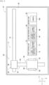
Fig. 1 is a diagram illustrating a circuit formation device. -
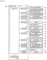
Fig. 2 is a block diagram illustrating a control device. -
Fig. 3 is a cross-sectional view illustrating a heat-sensitive release film adhered to a pallet. -
Fig. 4 is a cross-sectional view illustrating a circuit board in a state in which a resin laminate is formed. -
Fig. 5 is a cross-sectional view illustrating a circuit board in a state in which wiring is formed on the resin laminate. -
Fig. 6 is a plan view illustrating a pallet in a state in which the heat-sensitive release film is not adhered when whether the heat-sensitive release film is adhered is determined using a mark. -
Fig. 7 is a plan view illustrating a pallet in a state in which the heat-sensitive release film is adhered when whether the heat-sensitive release film is adhered is determined using a mark. -
Fig. 8 is a plan view illustrating a pallet in a state in which the heat-sensitive release film is not adhered when whether the heat-sensitive release film is adhered is determined using a brightness value. -
Fig. 9 is a plan view illustrating a pallet in a state in which the heat-sensitive release film is adhered when whether the heat-sensitive release film is adhered is determined using a brightness value. -
Fig. 10 is a plan view illustrating a pallet in a state in which the heat-sensitive release film is not adhered when whether the heat-sensitive release film is adhered is determined using a boundary line between the heat-sensitive release film and the pallet. -
Fig. 11 is a plan view illustrating a pallet in a state in which the heat-sensitive release film is adhered when whether the heat-sensitive release film is adhered is determined using a boundary line between the heat-sensitive release film and the pallet. -
Fig. 12 is a plan view illustrating a pallet when an adhesion position of the heat-sensitive release film is calculated based on the boundary line between the heat-sensitive release film and the pallet. -
Fig. 1 illustratescircuit formation device 10.Circuit formation device 10 includesconveyance device 20,first shaping unit 22,second shaping unit 24,imaging unit 26, and control device 28 (refer toFig. 2 ).Conveyance device 20,first shaping unit 22,second shaping unit 24, andimaging unit 26 are disposed onbase 29 ofcircuit formation device 10.Base 29 has a generally rectangular shape, and in the following description, a longitudinal direction ofbase 29 will be referred to as an X-axis direction, a shorter direction ofbase 29 will be referred to as a Y-axis direction, and a direction orthogonal to both the X-axis direction and the Y-axis direction will be referred to as a Z-axis direction. -
Conveyance device 20 includesX-axis slide mechanism 30 and Y-axis slide mechanism 32.X-axis slide mechanism 30 includesX-axis slide rail 34 andX-axis slider 36.X-axis slide rail 34 is disposed onbase 29 to extend in the X-axis direction.X-axis slider 36 is held byX-axis slide rail 34 to be slidable in the X-axis direction.X-axis slide mechanism 30 further includes electromagnetic motor 38 (refer toFig. 2 ), andX-axis slider 36 is moved to any position in the X-axis direction by drivingelectromagnetic motor 38. In addition, Y-axis slide mechanism 32 includes Y-axis slide rail 50 andstage 52. Y-axis slide rail 50 is disposed onbase 29 to extend in the Y-axis direction and is movable in the X-axis direction. One end portion of Y-axis slide rail 50 is coupled toX-axis slider 36.Stage 52 is held on Y-axis slide rail 50 to be slidable in the Y-axis direction. Furthermore, Y-axis slide mechanism 32 includes electromagnetic motor 56 (refer toFig. 2 ), andstage 52 is moved to any position in the Y-axis direction by drivingelectromagnetic motor 56. In this manner,stage 52 is moved to any position onbase 29 by drivingX-axis slide mechanism 30 and Y-axis slide mechanism 32. -
Stage 52 includesbase plate 60,holding device 62, lifting and lowering device 64 (refer toFig. 2 ), and heater 66 (refer toFig. 2 ).Base plate 60 is formed in a flat plate shape, and pallet 70 (refer toFig. 3 ) is placed on an upper surface thereof.Holding devices 62 are provided on both side portions ofbase plate 60 in the X-axis direction. Then, both edge portions ofpallet 70 placed onbase plate 60 in the X-axis direction are sandwiched by holdingdevices 62, so thatpallet 70 is fixedly held. In addition, lifting and loweringdevice 64 is disposed belowbase plate 60, and lifts and lowersbase plate 60.Heater 66 is incorporated inbase plate 60 andheats pallet 70 placed onbase plate 60. -
First shaping unit 22 is a unit for shaping wiring of a circuit board, and includesfirst printing section 72 and sinteringsection 74.First printing section 72 includes inkjet head 76 (refer toFig. 2 ), and inkjethead 76 linearly discharges metal ink. The metal ink is ink obtained by dispersing nanometer-sized metal fine particles, for example, silver fine particles in a solvent. A surface of the metal fine particles is coated with a dispersant and aggregation in the solvent is prevented. Further,inkjet head 76 discharges the metal ink from multiple nozzles by, for example, a piezo method using a piezoelectric element. -
Sintering section 74 includes infrared irradiation device 78 (refer toFig. 2 ).Infrared irradiation device 78 is a device for irradiating the discharged metal ink with infrared light, and the metal ink irradiated with infrared light is sintered to form the wiring. Sintering of the metal ink is, for example, a phenomenon in which evaporation of a solvent or decomposition of a protective film of metal fine particles, that is, a dispersant is performed by applying energy, so that conductivity is increased by contacting or fusing the metal fine particles. Then, the metal ink is sintered to form a metal wiring. - In addition,
second shaping unit 24 is a unit for shaping a resin layer of a circuit board, and includessecond printing section 84 andcuring section 86.Second printing section 84 includes inkjet head 88 (refer toFig. 2 ), andinkjet head 88 discharges an ultraviolet curable resin. The ultraviolet curable resin is a resin that is cured by irradiation with ultraviolet light.Inkjet head 88 may be, for example, a piezo type inkjet head using a piezoelectric element, or may be a thermal type inkjet head in which a resin is heated to generate air bubbles, which are discharged from multiple nozzles. -
Curing section 86 includes flattening device 90 (refer toFig. 2 ) and irradiation device 92 (refer toFig. 2 ). Flatteningdevice 90 flattens an upper surface of the ultraviolet curable resin discharged byinkjet head 88, and for example, scrapes up excess resin by a roller or a blade while smoothening the surface of the ultraviolet curable resin, to make the thickness of the ultraviolet curable resin uniform. In addition,irradiation device 92 includes a mercury lamp or LED as a light source, and irradiates the discharged ultraviolet curable resin with ultraviolet light. As a result, the discharged ultraviolet curable resin is cured to form a resin layer. -
Imaging unit 26 is a unit forimaging pallet 70 placed onbase plate 60 ofstage 52, and includescamera 100.Camera 100 is disposed abovebase 29 in a posture facing downward, and images the upper surface ofpallet 70 placed onbase plate 60 ofstage 52 from the above. - As illustrated in
Fig. 2 ,control device 28 includescontroller 110,multiple drive circuits 112,image processing device 114, andstorage device 116.Multiple drive circuits 112 are connected toelectromagnetic motors device 62, lifting and loweringdevice 64,heater 66,inkjet head 76,infrared irradiation device 78,inkjet head 88, flatteningdevice 90, andirradiation device 92.Controller 110 includes CPU, ROM, RAM, and the like, is mainly a computer, and is connected tomultiple drive circuits 112. Thus, the operations ofconveyance device 20, first shapingunit 22,second shaping unit 24, andimaging unit 26 are controlled bycontroller 110.Controller 110 is connected toimage processing device 114.Image processing device 114 is for processing the imaging data obtained bycamera 100, andcontroller 110 acquires various information from the imaging data.Storage device 116 stores various information determined based on the imaging data. - In
circuit formation device 10, in the above-described configuration, a resin laminate is formed onpallet 70 placed onbase plate 60 ofstage 52, and wiring is formed on the upper surface of the resin laminate, whereby a circuit board is formed. - Specifically, as illustrated in
Fig. 3 , first, an operator adheres heat-sensitive release film 120 to the upper surface ofpallet 70 placed onbase plate 60 ofstage 52. Since heat-sensitive release film 120 has adhesiveness, heat-sensitive release film 120 appropriately adheres to the upper surface ofpallet 70. A circuit board is formed on heat-sensitive release film 120, and the adherence of heat-sensitive release film 120 to pallet 70 prevents a deviation of the circuit board during circuit formation. Since the adhesiveness of heat-sensitive release film 120 decreases by heating, heat-sensitive release film 120 together with the circuit board formed on heat-sensitive release film 120 can be easily released frompallet 70 by heating heat-sensitive release film 120 after the circuit board is formed on heat-sensitive release film 120. - When heat-
sensitive release film 120 is adhered onpallet 70,stage 52 is moved below second shapingunit 24. Insecond shaping unit 24, as illustrated inFig. 4 ,resin laminate 122 is formed on heat-sensitive release film 120.Resin laminate 122 is formed by repeating the discharge of the ultraviolet curable resin frominkjet head 88 and the irradiation with ultraviolet light byirradiation device 92 to the discharged ultraviolet curable resin. - Specifically, in
second printing section 84 ofsecond shaping unit 24,inkjet head 88 discharges the ultraviolet curable resin in a thin film shape on the upper surface of heat-sensitive release film 120. Subsequently, when the ultraviolet curable resin is discharged in the thin film shape, the ultraviolet curable resin is flattened by flatteningdevice 90 in curingsection 86 so that the ultraviolet curable resin has a uniform film thickness.Irradiation device 92 irradiates the thin film-shaped ultraviolet curable resin with ultraviolet light. As a result, thin film-shapedresin layer 124 is formed on heat-sensitive release film 120. - Subsequently,
inkjet head 88 discharges the ultraviolet curable resin in a thin film shape onto thin film-shapedresin layer 124. The thin film-shaped ultraviolet curable resin is flattened by flatteningdevice 90,irradiation device 92 irradiates the ultraviolet curable resin discharged in a thin film shape with ultraviolet light, and thus thin film-shapedresin layer 124 is laminated on thin film-shapedresin layer 124. As described above, the discharge of the ultraviolet curable resin on thin film-shapedresin layer 124 and the irradiation with the ultraviolet light are repeated, andmultiple resin layers 124 are laminated and thusresin laminate 122 is formed. - Next, when
resin laminate 122 is formed,stage 52 is moved below first shapingunit 22. Infirst printing section 72 offirst shaping unit 22, as illustrated inFig. 5 ,inkjet head 76 linearly dischargesmetal ink 130 on the upper surface ofresin laminate 122 in accordance with the circuit pattern. Subsequently,infrared irradiation device 78 irradiatesmetal ink 130 discharged in accordance with the circuit pattern with infrared light insintering section 74 offirst shaping unit 22. As a result,metal ink 130 is sintered, andwiring 132 is formed on the upper surface ofresin laminate 122. - As described above,
resin laminate 122 is formed on the upper surface of heat-sensitive release film 120, andwiring 132 is formed on the upper surface ofresin laminate 122, wherebycircuit board 136 is formed on heat-sensitive release film 120 on upper surface ofpallet 70. In order to release heat-sensitive release film 120 from formedcircuit board 136, heat-sensitive release film 120 is heated byheater 66 incorporated inbase plate 60. As a result, the adhesiveness of heat-sensitive release film 120 decreases, so thatcircuit board 136 can be easily released frompallet 70 together with heat-sensitive release film 120. Then, heat-sensitive release film 120 is released fromcircuit board 136, whereby the formation ofcircuit board 136 is completed. - However, since heat-
sensitive release film 120 is adhered to pallet 70 by the operator,circuit board 136 may be directly formed onpallet 70 without heat-sensitive release film 120 being adhered topallet 70. In other words,resin laminate 122 may be formed by directly discharging the ultraviolet curable resin onpallet 70. In such a case, whencircuit board 136 is released frompallet 70 aftercircuit board 136 is formed by bringingpallet 70 andresin laminate 122 into close contact with each other,resin laminate 122 ofcircuit board 136 may be damaged. Therefore, incircuit formation device 10, beforecircuit board 136 is formed onpallet 70,pallet 70 is imaged inimaging unit 26, and it is determined whether heat-sensitive release film 120 is adhered to pallet 70 based on the imaging data obtained through the imaging. - Specifically, as illustrated in
Fig. 6 ,mark 150 is marked on the upper surface ofpallet 70, and the position at whichmark 150 is marked is an adhesion planned position where heat-sensitive release film 120 is to be adhered topallet 70. When pallet 70 is set onbase plate 60 ofstage 52,stage 52 is moved belowimaging unit 26 beforeresin laminate 122 is formed onpallet 70. Then, inimaging unit 26,camera 100 images pallet 70 set onbase plate 60. Since the imaging range ofcamera 100 is narrow, predetermined range 152 (hereinafter, referred to as a "first range") (refer toFigs. 6 and7 ) including the position ofmark 150 onpallet 70 is set, andfirst range 152 is imaged bycamera 100. The imaging data obtained through the imaging is then analyzed bycontroller 110, and based on the imaging data, it is determined whether heat-sensitive release film 120 is adhered topallet 70. That is, based on the imaging data infirst range 152, the presence or absence ofmark 150 is determined. At this time, based on the imaging data infirst range 152, in a case where it is determined thatmark 150 is present as illustrated inFig. 6 , it is determined that heat-sensitive release film 120 is not adhered to pallet 70. On the other hand, based on the imaging data infirst range 152, as illustrated inFig. 7 , in a case where it is determined that there is nomark 150, it is determined that heat-sensitive release film 120 is adhered topallet 70. As a result, it is possible to determine whether heat-sensitive release film 120 is adhered topallet 70. - However, in a case where heat-
sensitive release film 120 is a film having a high transparency, even if heat-sensitive release film 120 is adhered topallet 70,mark 150 may be visible through heat-sensitive release film 120. In other words, even if heat-sensitive release film 120 is adhered topallet 70, it may be determined that there ismark 150 based on the imaging data. In such a case, it is erroneously determined that heat-sensitive release film 120 is not adhered to pallet 70 although heat-sensitive release film 120 is adhered topallet 70. In view of such a case, it is determined not only whether heat-sensitive release film 120 is adhered to pallet 70 based on the presence or absence ofmark 150, but also whether heat-sensitive release film 120 is adhered based on the brightness value of the imaging data. - Specifically, predetermined range 160 (hereinafter, referred to as a "second range") (refer to
Figs. 8 and9 ) is set at a position different from the position ofmark 150 ofpallet 70 and at the adhesion planned position where heat-sensitive release film 120 is to be adhered topallet 70. As illustrated inFig. 8 , inpallet 70 in a state in which heat-sensitive release film 120 is not adhered,second range 160 is imaged in advance bycamera 100, and the brightness value is calculated in advance based on the imaging data. That is, the brightness value ofsecond range 160 of pallet 70 (hereinafter, referred to as a "pallet brightness value") is calculated in advance. Further, as illustrated inFig. 9 , inpallet 70 in a state in which heat-sensitive release film 120 is adhered,second range 160 is imaged in advance bycamera 100, and the brightness value is calculated in advance based on the imaging data. That is, the brightness value ofsecond range 160 of heat-sensitive release film 120 adhered to pallet 70 (hereinafter, referred to as a "film brightness value") is calculated in advance. An intermediate value between the pallet brightness value and the film brightness value, such as an average value is calculated as a threshold value, and the threshold value, the pallet brightness value, and the film brightness value are set in advance incontroller 110. - As described above, using a threshold value set in advance, it is determined whether heat-
sensitive release film 120 is adhered topallet 70. Specifically, as described above, afterfirst range 152 is imaged bycamera 100 in order to determine the presence or absence ofmark 150,second range 160 is imaged bycamera 100. Then, incontroller 110, the imaging data obtained through the imaging is analyzed, and the brightness value of second range 160 (hereinafter, referred to as a "calculated brightness value") is calculated. Subsequently, incontroller 110, it is determined the calculated brightness value is closer to any one of the pallet brightness value and the film brightness value with reference to the threshold value. At this time, in a case where it is determined that the calculated brightness value is close to the pallet brightness value, it is determined that heat-sensitive release film 120 is not adhered to pallet 70. On the other hand, in a case where it is determined that the calculated brightness value is close to the film brightness value, it is determined that heat-sensitive release film 120 is adhered topallet 70. As a result, in addition to the method of determining whether heat-sensitive release film 120 is adhered usingmark 150, whether heat-sensitive release film 120 is adhered is determined using the brightness value, so that the accuracy of determining whether heat-sensitive release film 120 is adhered can be increased. - Further, in
circuit formation device 10, whether heat-sensitive release film 120 is adhered is determined using not only the first determination method for determining whether heat-sensitive release film 120 is adhered usingmark 150 and the second determination method for determining whether heat-sensitive release film 120 is adhered using the brightness value but also the third determination method. Specifically, predetermined range 170 (hereinafter, referred to as a "third range") (refer toFigs. 10 and11 ) including a boundary between an adhesion planned position where heat-sensitive release film 120 is to be adhered onpallet 70 and a position where heat-sensitive release film 120 is not planned to be adhered is set. That is,third range 170 including the edge of the adhesion planned position of heat-sensitive release film 120 onpallet 70 is set. Therefore, as described above, afterfirst range 152 andsecond range 160 are imaged bycamera 100,third range 170 is imaged bycamera 100. Then, the imaging data obtained through the imaging is analyzed bycontroller 110, and based on the imaging data, a boundary between the adhesion planned position of heat-sensitive release film 120 onpallet 70 and the position where heat-sensitive release film 120 is not planned to be adhered, that is, the presence or absence of a boundary line between heat-sensitive release film 120 andpallet 70 is determined. At this time, based on the imaging data inthird range 170, as illustrated inFig. 10 , in a case where it is determined that there is no boundary line between heat-sensitive release film 120 andpallet 70, it is determined that heat-sensitive release film 120 is not adhered to pallet 70. On the other hand, based on the imaging data inthird range 170, as illustrated inFig. 11 , when it is determined that there is a boundary line between heat-sensitive release film 120 andpallet 70, it is determined that heat-sensitive release film 120 is adhered topallet 70. As a result, it is possible to determine whether heat-sensitive release film 120 is adhered topallet 70. - As described above, in
circuit formation device 10, whether heat-sensitive release film 120 is adhered is determined using the three determination methods which include the first determination method based on the presence or absence ofmark 150, the second determination method based on the brightness value, and the third determination method based on the presence or absence of the boundary line between heat-sensitive release film 120 andpallet 70. As a result, it is possible to appropriately determine whether heat-sensitive release film 120 is adhered topallet 70. As the three determination methods are performed, and in a case where it is determined that heat-sensitive release film 120 is adhered to pallet 70 by at least one determination method among the three determination methods, the shaping of the circuit board is performed. On the other hand, in all of the three determination methods, in a case where it is determined that heat-sensitive release film 120 is not adhered to pallet 70, the error notification is made without performing the shaping of the circuit board. - In addition, it is considered that the determination method by which whether heat-
sensitive release film 120 is adhered can be determined is different according to the characteristics of heat-sensitive release film 120, specifically, for example, the transparency, the brightness value, the reflectance, and the like of heat-sensitive release film 120. That is, for example, in heat-sensitive release film A, it is determined that heat-sensitive release film 120 is adhered to pallet 70 by the first determination method and the third determination method, and in heat-sensitive release film B, it is determined that heat-sensitive release film 120 is adhered to pallet 70 by the second determination method. For this reason, in a case where it is determined that heat-sensitive release film 120 is adhered topallet 70, the determination method for determining that heat-sensitive release film 120 is adhered to pallet 70 and the type of heat-sensitive release film are stored instorage device 116 in association with each other. That is, for example, heat-sensitive release film A and the first determination method and the third determination method are stored instorage device 116 in association with each other, and heat-sensitive release film B and the second determination method are stored instorage device 116 in association with each other. When it is determined again whether the same type of heat-sensitive release film is adhered topallet 70, whether the heat-sensitive release film is adhered is determined using the determination method stored instorage device 116 in association with the type of heat-sensitive release film. In other words, in a case where it is determined whether heat-sensitive release film A is adhered to pallet 70 for a second time or later, whether heat-sensitive release film A is adhered is determined using the first determination method and the third determination method stored instorage device 116 in association with heat-sensitive release film A. As a result, it is possible to appropriately determine whether the heat-sensitive release film is adhered and to shorten the time required for the determination. - In addition, in a case where it is determined that the heat-sensitive release film is adhered to pallet 70 by the third determination method, that is, in a case where it is determined that there is a boundary line between heat-
sensitive release film 120 andpallet 70 based on the imaging data, the adhesion position of heat-sensitive release film 120 is calculated based on the boundary line between heat-sensitive release film 120 andpallet 70. Specifically, twopredetermined ranges Fig. 12 ) including the two corners of the adhesion planned position of heat-sensitive release film 120 onpallet 70 are set. Twofourth ranges sensitive release film 120 at the adhesion planned position of heat-sensitive release film 120. Then, after it is determined that there is a boundary line between heat-sensitive release film 120 andpallet 70 based on the imaging data, twofourth ranges camera 100. Then, incontroller 110, the imaging data of twofourth ranges sensitive release film 120 are calculated. A first one of the two corners is formed by twosides sensitive release film 120, and a second one of the two corners is formed by twosides sensitive release film 120. For this reason, the positions of four sides 190 of heat-sensitive release film 120 are calculated based on the positions of the two corners facing each other about the center of heat-sensitive release film 120, and the adhesion position of heat-sensitive release film 120 is further calculated based on the positions of four sides 190 of heat-sensitive release film 120. Then,circuit board 136 is formed on heat-sensitive release film 120 using the calculated adhesion position of heat-sensitive release film 120. That is, the discharging of the ultraviolet curable resin and the discharging of the metal ink are performed using the calculated adhesion position of heat-sensitive release film 120. In this manner, the adhesion position of heat-sensitive release film 120 based on the boundary line between heat-sensitive release film 120 andpallet 70 is calculated andcircuit board 136 is formed using the adhesion position of heat-sensitive release film 120, whereby the forming accuracy ofcircuit board 136 can be increased. - In the above embodiment,
circuit formation device 10 is an example of a shaping device.Control device 28 is an example of a determination device.Pallet 70 is an example of a pallet. Heat-sensitive release film 120 is an example of a film.Circuit board 136 is an example of a three-dimensional shaped object.Mark 150 is an example of a mark. - The present invention is not limited to the above embodiment, and can be performed in various aspects to which various modifications and improvements are applied based on the knowledge of those skilled in the art. For example, in the above embodiment, it is determined whether the heat-sensitive release film is adhered to pallet 70 based on the pallet brightness value, the film brightness value, and the threshold value, but it may be determined whether the heat-sensitive release film is adhered to pallet 70 based on one of the pallet brightness value and the film brightness value. That is, for example, the brightness value of a predetermined range having the pallet brightness value as a center (hereinafter, referred to as a "pallet brightness value set range") is set. When the calculated brightness value is within the pallet brightness value set range, it is determined that the heat-sensitive release film is not adhered to pallet 70, and when the calculated brightness value is outside the pallet brightness value set range, it may be determined that the heat-sensitive release film is adhered to
pallet 70. In addition, the present invention is not limited to the pallet brightness value and the film brightness value, and various color information can be adopted as long as it is information indicating the color of the pallet and the heat-sensitive release film (hereinafter, referred to as "color information"). For example, as the color information, information indicating various colors such as brightness, saturation, color tone, and the like can be adopted. - In addition, in the above embodiment, since
camera 100 having a narrow imaging range is adopted, each offirst range 152,second range 160,third range 170, and fourth range 180 is individually imaged. On the other hand, in a case where a camera having a larger imaging range than the heat-sensitive release film is adopted, all offirst range 152,second range 160,third range 170, and fourth range 180 can be imaged at one time. As a result, it is possible to reduce the time required for imaging. - In addition, in the above embodiment, the ultraviolet curable resin is adopted as the resin for shaping the three-dimensional shaped object, but various curable resins such as a two-liquid mixed curable resin, a thermosetting resin, and a thermoplastic resin can be adopted. In addition, the material for shaping the three-dimensional shaped object is not limited to a resin, and various materials can be adopted as long as the material is a material for curing the fluid.
- In addition, in the above embodiment,
circuit board 136 is adopted as a three-dimensional shaped object, but various three-dimensional shaped objects such as a figure can be adopted. - 10: circuit formation device (shaping device), 28: control device (determination device), 70: pallet, 120: heat-sensitive release film (film), 136: circuit board (three-dimensional shaped object), 150: mark.
Claims (5)
- A determination device used in a shaping device in which a three-dimensional shaped object is shaped on an upper surface of a film adhered to a pallet, wherein
the determination device determines whether the film is adhered to the pallet based on imaging data of the pallet. - The determination device according to claim 1, wherein
the determination device determines whether the film is adhered to the pallet based on a presence or absence of a mark marked at an adhesion planned position of the film on the pallet. - The determination device according to claim 1 or 2, wherein
the determination device determines whether the film is adhered to the pallet based on at least one of color information indicating color of the pallet or color information of the film adhered to the pallet. - The determination device according to any one of claims 1 to 3, wherein
the determination device determines whether the film is adhered to the pallet based on a presence or absence of a boundary between the pallet and the film. - The determination device according to claim 4, wherein
in a case where it is determined that the film is adhered to the pallet based on the presence or absence of the boundary between the pallet and the film, the determination device calculates an adhesion position of the film on the pallet based on a position of the boundary.
Applications Claiming Priority (1)
| Application Number | Priority Date | Filing Date | Title |
|---|---|---|---|
| PCT/JP2021/010080 WO2022190360A1 (en) | 2021-03-12 | 2021-03-12 | Determination device |
Publications (3)
| Publication Number | Publication Date |
|---|---|
| EP4306299A1 true EP4306299A1 (en) | 2024-01-17 |
| EP4306299A4 EP4306299A4 (en) | 2024-05-15 |
| EP4306299B1 EP4306299B1 (en) | 2025-06-25 |
Family
ID=83226530
Family Applications (1)
| Application Number | Title | Priority Date | Filing Date |
|---|---|---|---|
| EP21930212.2A Active EP4306299B1 (en) | 2021-03-12 | 2021-03-12 | Determination device |
Country Status (5)
| Country | Link |
|---|---|
| US (1) | US20240227303A9 (en) |
| EP (1) | EP4306299B1 (en) |
| JP (1) | JP7573723B2 (en) |
| CN (1) | CN116917110B (en) |
| WO (1) | WO2022190360A1 (en) |
Families Citing this family (1)
| Publication number | Priority date | Publication date | Assignee | Title |
|---|---|---|---|---|
| CN116917110B (en) * | 2021-03-12 | 2025-12-12 | 株式会社富士 | Determination device |
Family Cites Families (13)
| Publication number | Priority date | Publication date | Assignee | Title |
|---|---|---|---|---|
| JP4304965B2 (en) | 2002-11-11 | 2009-07-29 | トヨタ自動車株式会社 | Laminated modeling apparatus and manufacturing method |
| JP4193579B2 (en) * | 2003-05-21 | 2008-12-10 | 凸版印刷株式会社 | Film pasting position inspection method and inspection apparatus |
| PL2093041T3 (en) * | 2006-10-17 | 2013-08-30 | Nitto Denko Corp | Optical member adhering method, and apparatus using the method |
| GB0819935D0 (en) * | 2008-10-30 | 2008-12-10 | Mtt Technologies Ltd | Additive manufacturing apparatus and method |
| US20130075954A1 (en) * | 2011-09-26 | 2013-03-28 | 3D Systems, Inc. | Solid Imaging Systems, Components Thereof, and Methods of Solid Imaging |
| JP5902569B2 (en) * | 2012-06-29 | 2016-04-13 | ヤマハ発動機株式会社 | Electronic component mounting method and mounting device therefor |
| JP5724152B1 (en) * | 2013-05-17 | 2015-05-27 | 住友化学株式会社 | Optical display device production system |
| CN111687416A (en) * | 2014-11-14 | 2020-09-22 | 株式会社尼康 | Molding apparatus and molding method |
| JP6900920B2 (en) * | 2018-02-20 | 2021-07-07 | 新東工業株式会社 | Stage mechanism, additional manufacturing equipment and additional manufacturing method |
| CN209388070U (en) * | 2018-11-21 | 2019-09-13 | 惠科股份有限公司 | Display panel and display device |
| EP3715095A1 (en) * | 2019-03-27 | 2020-09-30 | Concept Laser GmbH | Apparatus for additively manufacturing three-dimensional objects |
| CN211105636U (en) * | 2019-09-17 | 2020-07-28 | 上海联泰科技股份有限公司 | Optical calibration tool and 3D printing equipment |
| CN116917110B (en) * | 2021-03-12 | 2025-12-12 | 株式会社富士 | Determination device |
-
2021
- 2021-03-12 CN CN202180093227.3A patent/CN116917110B/en active Active
- 2021-03-12 JP JP2023505046A patent/JP7573723B2/en active Active
- 2021-03-12 EP EP21930212.2A patent/EP4306299B1/en active Active
- 2021-03-12 WO PCT/JP2021/010080 patent/WO2022190360A1/en not_active Ceased
- 2021-03-12 US US18/547,360 patent/US20240227303A9/en active Pending
Also Published As
| Publication number | Publication date |
|---|---|
| JPWO2022190360A1 (en) | 2022-09-15 |
| EP4306299B1 (en) | 2025-06-25 |
| US20240131797A1 (en) | 2024-04-25 |
| EP4306299A4 (en) | 2024-05-15 |
| CN116917110A (en) | 2023-10-20 |
| US20240227303A9 (en) | 2024-07-11 |
| JP7573723B2 (en) | 2024-10-25 |
| WO2022190360A1 (en) | 2022-09-15 |
| CN116917110B (en) | 2025-12-12 |
Similar Documents
| Publication | Publication Date | Title |
|---|---|---|
| JP7670731B2 (en) | Electrical circuit forming method and electrical circuit forming device | |
| US11006529B2 (en) | Circuit forming method | |
| EP4306299B1 (en) | Determination device | |
| EP4450259A1 (en) | Three-dimensional laminate shaping device | |
| TW202218498A (en) | Systems and methods for printing conformal materials on component edges at high resolution | |
| JP7053832B2 (en) | Circuit forming method and circuit forming device | |
| WO2022195800A1 (en) | Electronic part mounting method and electronic part mounting device | |
| JP7591979B2 (en) | Three-dimensional modeling device and modeling method | |
| US20250142734A1 (en) | Electrical circuit formation method, and electrical circuit formation device | |
| JP7411452B2 (en) | Circuit formation method | |
| WO2024062605A1 (en) | Circuit forming device and circuit forming method | |
| US20240422916A1 (en) | Circuit-forming method and circuit-forming apparatus | |
| EP4507470A1 (en) | Electrical circuit formation method and electrical circuit formation device | |
| JP7670801B2 (en) | Printing machine, work system, and printing method | |
| EP4529368A1 (en) | Manufacturing method and manufacturing device | |
| JP7516576B2 (en) | Three-dimensional modeling device and pallet transfer method | |
| EP4590080A1 (en) | Resin laminate formation device and resin laminate formation method | |
| JP7783298B2 (en) | Circuit forming method and circuit forming device | |
| US12414240B2 (en) | Circuit forming method and circuit forming device | |
| JP2024168901A (en) | Circuit board forming apparatus and circuit board forming method | |
| US20240390985A1 (en) | Circuit forming method and information processing device | |
| WO2022201231A1 (en) | Determination device, molding method, and molding device |
Legal Events
| Date | Code | Title | Description |
|---|---|---|---|
| STAA | Information on the status of an ep patent application or granted ep patent |
Free format text: STATUS: THE INTERNATIONAL PUBLICATION HAS BEEN MADE |
|
| PUAI | Public reference made under article 153(3) epc to a published international application that has entered the european phase |
Free format text: ORIGINAL CODE: 0009012 |
|
| STAA | Information on the status of an ep patent application or granted ep patent |
Free format text: STATUS: REQUEST FOR EXAMINATION WAS MADE |
|
| 17P | Request for examination filed |
Effective date: 20230809 |
|
| AK | Designated contracting states |
Kind code of ref document: A1 Designated state(s): AL AT BE BG CH CY CZ DE DK EE ES FI FR GB GR HR HU IE IS IT LI LT LU LV MC MK MT NL NO PL PT RO RS SE SI SK SM TR |
|
| A4 | Supplementary search report drawn up and despatched |
Effective date: 20240415 |
|
| RIC1 | Information provided on ipc code assigned before grant |
Ipc: B29C 37/00 20060101ALI20240410BHEP Ipc: B33Y 50/02 20150101ALI20240410BHEP Ipc: B33Y 30/00 20150101ALI20240410BHEP Ipc: B33Y 10/00 20150101ALI20240410BHEP Ipc: B29C 64/393 20170101ALI20240410BHEP Ipc: B29C 64/245 20170101AFI20240410BHEP |
|
| DAV | Request for validation of the european patent (deleted) | ||
| DAX | Request for extension of the european patent (deleted) | ||
| GRAP | Despatch of communication of intention to grant a patent |
Free format text: ORIGINAL CODE: EPIDOSNIGR1 |
|
| STAA | Information on the status of an ep patent application or granted ep patent |
Free format text: STATUS: GRANT OF PATENT IS INTENDED |
|
| RIC1 | Information provided on ipc code assigned before grant |
Ipc: G01N 21/84 20060101ALI20250131BHEP Ipc: B29C 37/00 20060101ALI20250131BHEP Ipc: B33Y 50/02 20150101ALI20250131BHEP Ipc: B33Y 30/00 20150101ALI20250131BHEP Ipc: B33Y 10/00 20150101ALI20250131BHEP Ipc: B29C 64/393 20170101ALI20250131BHEP Ipc: B29C 64/245 20170101AFI20250131BHEP |
|
| INTG | Intention to grant announced |
Effective date: 20250212 |
|
| GRAS | Grant fee paid |
Free format text: ORIGINAL CODE: EPIDOSNIGR3 |
|
| GRAA | (expected) grant |
Free format text: ORIGINAL CODE: 0009210 |
|
| STAA | Information on the status of an ep patent application or granted ep patent |
Free format text: STATUS: THE PATENT HAS BEEN GRANTED |
|
| P01 | Opt-out of the competence of the unified patent court (upc) registered |
Free format text: CASE NUMBER: APP_22347/2025 Effective date: 20250512 |
|
| AK | Designated contracting states |
Kind code of ref document: B1 Designated state(s): AL AT BE BG CH CY CZ DE DK EE ES FI FR GB GR HR HU IE IS IT LI LT LU LV MC MK MT NL NO PL PT RO RS SE SI SK SM TR |
|
| REG | Reference to a national code |
Ref country code: GB Ref legal event code: FG4D |
|
| REG | Reference to a national code |
Ref country code: CH Ref legal event code: EP |
|
| REG | Reference to a national code |
Ref country code: CH Ref legal event code: EP |
|
| REG | Reference to a national code |
Ref country code: IE Ref legal event code: FG4D |
|
| REG | Reference to a national code |
Ref country code: DE Ref legal event code: R096 Ref document number: 602021033116 Country of ref document: DE |
|
| PG25 | Lapsed in a contracting state [announced via postgrant information from national office to epo] |
Ref country code: FI Free format text: LAPSE BECAUSE OF FAILURE TO SUBMIT A TRANSLATION OF THE DESCRIPTION OR TO PAY THE FEE WITHIN THE PRESCRIBED TIME-LIMIT Effective date: 20250625 |
|
| REG | Reference to a national code |
Ref country code: LT Ref legal event code: MG9D |
|
| PG25 | Lapsed in a contracting state [announced via postgrant information from national office to epo] |
Ref country code: NO Free format text: LAPSE BECAUSE OF FAILURE TO SUBMIT A TRANSLATION OF THE DESCRIPTION OR TO PAY THE FEE WITHIN THE PRESCRIBED TIME-LIMIT Effective date: 20250925 Ref country code: GR Free format text: LAPSE BECAUSE OF FAILURE TO SUBMIT A TRANSLATION OF THE DESCRIPTION OR TO PAY THE FEE WITHIN THE PRESCRIBED TIME-LIMIT Effective date: 20250926 |
|
| PG25 | Lapsed in a contracting state [announced via postgrant information from national office to epo] |
Ref country code: BG Free format text: LAPSE BECAUSE OF FAILURE TO SUBMIT A TRANSLATION OF THE DESCRIPTION OR TO PAY THE FEE WITHIN THE PRESCRIBED TIME-LIMIT Effective date: 20250625 |
|
| PG25 | Lapsed in a contracting state [announced via postgrant information from national office to epo] |
Ref country code: HR Free format text: LAPSE BECAUSE OF FAILURE TO SUBMIT A TRANSLATION OF THE DESCRIPTION OR TO PAY THE FEE WITHIN THE PRESCRIBED TIME-LIMIT Effective date: 20250625 |
|
| PG25 | Lapsed in a contracting state [announced via postgrant information from national office to epo] |
Ref country code: RS Free format text: LAPSE BECAUSE OF FAILURE TO SUBMIT A TRANSLATION OF THE DESCRIPTION OR TO PAY THE FEE WITHIN THE PRESCRIBED TIME-LIMIT Effective date: 20250925 |
|
| PG25 | Lapsed in a contracting state [announced via postgrant information from national office to epo] |
Ref country code: LV Free format text: LAPSE BECAUSE OF FAILURE TO SUBMIT A TRANSLATION OF THE DESCRIPTION OR TO PAY THE FEE WITHIN THE PRESCRIBED TIME-LIMIT Effective date: 20250625 |
|
| REG | Reference to a national code |
Ref country code: NL Ref legal event code: MP Effective date: 20250625 |
|
| PG25 | Lapsed in a contracting state [announced via postgrant information from national office to epo] |
Ref country code: NL Free format text: LAPSE BECAUSE OF FAILURE TO SUBMIT A TRANSLATION OF THE DESCRIPTION OR TO PAY THE FEE WITHIN THE PRESCRIBED TIME-LIMIT Effective date: 20250625 |
|
| PG25 | Lapsed in a contracting state [announced via postgrant information from national office to epo] |
Ref country code: PT Free format text: LAPSE BECAUSE OF FAILURE TO SUBMIT A TRANSLATION OF THE DESCRIPTION OR TO PAY THE FEE WITHIN THE PRESCRIBED TIME-LIMIT Effective date: 20251027 |
|
| REG | Reference to a national code |
Ref country code: AT Ref legal event code: MK05 Ref document number: 1806053 Country of ref document: AT Kind code of ref document: T Effective date: 20250625 |
|
| PG25 | Lapsed in a contracting state [announced via postgrant information from national office to epo] |
Ref country code: IS Free format text: LAPSE BECAUSE OF FAILURE TO SUBMIT A TRANSLATION OF THE DESCRIPTION OR TO PAY THE FEE WITHIN THE PRESCRIBED TIME-LIMIT Effective date: 20251025 |
|
| PG25 | Lapsed in a contracting state [announced via postgrant information from national office to epo] |
Ref country code: AT Free format text: LAPSE BECAUSE OF FAILURE TO SUBMIT A TRANSLATION OF THE DESCRIPTION OR TO PAY THE FEE WITHIN THE PRESCRIBED TIME-LIMIT Effective date: 20250625 Ref country code: SM Free format text: LAPSE BECAUSE OF FAILURE TO SUBMIT A TRANSLATION OF THE DESCRIPTION OR TO PAY THE FEE WITHIN THE PRESCRIBED TIME-LIMIT Effective date: 20250625 |
|
| PG25 | Lapsed in a contracting state [announced via postgrant information from national office to epo] |
Ref country code: CZ Free format text: LAPSE BECAUSE OF FAILURE TO SUBMIT A TRANSLATION OF THE DESCRIPTION OR TO PAY THE FEE WITHIN THE PRESCRIBED TIME-LIMIT Effective date: 20250625 |
|
| PG25 | Lapsed in a contracting state [announced via postgrant information from national office to epo] |
Ref country code: PL Free format text: LAPSE BECAUSE OF FAILURE TO SUBMIT A TRANSLATION OF THE DESCRIPTION OR TO PAY THE FEE WITHIN THE PRESCRIBED TIME-LIMIT Effective date: 20250625 |
|
| PG25 | Lapsed in a contracting state [announced via postgrant information from national office to epo] |
Ref country code: EE Free format text: LAPSE BECAUSE OF FAILURE TO SUBMIT A TRANSLATION OF THE DESCRIPTION OR TO PAY THE FEE WITHIN THE PRESCRIBED TIME-LIMIT Effective date: 20250625 |
|
| PG25 | Lapsed in a contracting state [announced via postgrant information from national office to epo] |
Ref country code: SK Free format text: LAPSE BECAUSE OF FAILURE TO SUBMIT A TRANSLATION OF THE DESCRIPTION OR TO PAY THE FEE WITHIN THE PRESCRIBED TIME-LIMIT Effective date: 20250625 |
|
| PG25 | Lapsed in a contracting state [announced via postgrant information from national office to epo] |
Ref country code: ES Free format text: LAPSE BECAUSE OF FAILURE TO SUBMIT A TRANSLATION OF THE DESCRIPTION OR TO PAY THE FEE WITHIN THE PRESCRIBED TIME-LIMIT Effective date: 20250625 |
|
| PG25 | Lapsed in a contracting state [announced via postgrant information from national office to epo] |
Ref country code: DK Free format text: LAPSE BECAUSE OF FAILURE TO SUBMIT A TRANSLATION OF THE DESCRIPTION OR TO PAY THE FEE WITHIN THE PRESCRIBED TIME-LIMIT Effective date: 20250625 |
|
| PGFP | Annual fee paid to national office [announced via postgrant information from national office to epo] |
Ref country code: DE Payment date: 20260128 Year of fee payment: 6 |
|
| PG25 | Lapsed in a contracting state [announced via postgrant information from national office to epo] |
Ref country code: IT Free format text: LAPSE BECAUSE OF FAILURE TO SUBMIT A TRANSLATION OF THE DESCRIPTION OR TO PAY THE FEE WITHIN THE PRESCRIBED TIME-LIMIT Effective date: 20250625 |
|
| PGFP | Annual fee paid to national office [announced via postgrant information from national office to epo] |
Ref country code: FR Payment date: 20260209 Year of fee payment: 6 |
|
| PLBE | No opposition filed within time limit |
Free format text: ORIGINAL CODE: 0009261 |
|
| STAA | Information on the status of an ep patent application or granted ep patent |
Free format text: STATUS: NO OPPOSITION FILED WITHIN TIME LIMIT |
|
| REG | Reference to a national code |
Ref country code: CH Ref legal event code: L10 Free format text: ST27 STATUS EVENT CODE: U-0-0-L10-L00 (AS PROVIDED BY THE NATIONAL OFFICE) Effective date: 20260507 |