EP4306218A1 - Horizontal grinder rotor, grinding bead driving device and horizontal grinder - Google Patents
Horizontal grinder rotor, grinding bead driving device and horizontal grinder Download PDFInfo
- Publication number
- EP4306218A1 EP4306218A1 EP23184523.1A EP23184523A EP4306218A1 EP 4306218 A1 EP4306218 A1 EP 4306218A1 EP 23184523 A EP23184523 A EP 23184523A EP 4306218 A1 EP4306218 A1 EP 4306218A1
- Authority
- EP
- European Patent Office
- Prior art keywords
- horizontal grinder
- rotors
- horizontal
- grinding
- rotor
- Prior art date
- Legal status (The legal status is an assumption and is not a legal conclusion. Google has not performed a legal analysis and makes no representation as to the accuracy of the status listed.)
- Pending
Links
Images



Classifications
-
- B—PERFORMING OPERATIONS; TRANSPORTING
- B02—CRUSHING, PULVERISING, OR DISINTEGRATING; PREPARATORY TREATMENT OF GRAIN FOR MILLING
- B02C—CRUSHING, PULVERISING, OR DISINTEGRATING IN GENERAL; MILLING GRAIN
- B02C17/00—Disintegrating by tumbling mills, i.e. mills having a container charged with the material to be disintegrated with or without special disintegrating members such as pebbles or balls
- B02C17/18—Details
- B02C17/20—Disintegrating members
-
- B—PERFORMING OPERATIONS; TRANSPORTING
- B02—CRUSHING, PULVERISING, OR DISINTEGRATING; PREPARATORY TREATMENT OF GRAIN FOR MILLING
- B02C—CRUSHING, PULVERISING, OR DISINTEGRATING IN GENERAL; MILLING GRAIN
- B02C17/00—Disintegrating by tumbling mills, i.e. mills having a container charged with the material to be disintegrated with or without special disintegrating members such as pebbles or balls
- B02C17/16—Mills in which a fixed container houses stirring means tumbling the charge
- B02C17/163—Stirring means
-
- B—PERFORMING OPERATIONS; TRANSPORTING
- B02—CRUSHING, PULVERISING, OR DISINTEGRATING; PREPARATORY TREATMENT OF GRAIN FOR MILLING
- B02C—CRUSHING, PULVERISING, OR DISINTEGRATING IN GENERAL; MILLING GRAIN
- B02C17/00—Disintegrating by tumbling mills, i.e. mills having a container charged with the material to be disintegrated with or without special disintegrating members such as pebbles or balls
- B02C17/002—Disintegrating by tumbling mills, i.e. mills having a container charged with the material to be disintegrated with or without special disintegrating members such as pebbles or balls with rotary cutting or beating elements
-
- B—PERFORMING OPERATIONS; TRANSPORTING
- B02—CRUSHING, PULVERISING, OR DISINTEGRATING; PREPARATORY TREATMENT OF GRAIN FOR MILLING
- B02C—CRUSHING, PULVERISING, OR DISINTEGRATING IN GENERAL; MILLING GRAIN
- B02C17/00—Disintegrating by tumbling mills, i.e. mills having a container charged with the material to be disintegrated with or without special disintegrating members such as pebbles or balls
- B02C17/10—Disintegrating by tumbling mills, i.e. mills having a container charged with the material to be disintegrated with or without special disintegrating members such as pebbles or balls with one or a few disintegrating members arranged in the container
-
- B—PERFORMING OPERATIONS; TRANSPORTING
- B33—ADDITIVE MANUFACTURING TECHNOLOGY
- B33Y—ADDITIVE MANUFACTURING, i.e. MANUFACTURING OF THREE-DIMENSIONAL [3D] OBJECTS BY ADDITIVE DEPOSITION, ADDITIVE AGGLOMERATION OR ADDITIVE LAYERING, e.g. BY 3D PRINTING, STEREOLITHOGRAPHY OR SELECTIVE LASER SINTERING
- B33Y80/00—Products made by additive manufacturing
-
- B—PERFORMING OPERATIONS; TRANSPORTING
- B02—CRUSHING, PULVERISING, OR DISINTEGRATING; PREPARATORY TREATMENT OF GRAIN FOR MILLING
- B02C—CRUSHING, PULVERISING, OR DISINTEGRATING IN GENERAL; MILLING GRAIN
- B02C17/00—Disintegrating by tumbling mills, i.e. mills having a container charged with the material to be disintegrated with or without special disintegrating members such as pebbles or balls
- B02C17/16—Mills in which a fixed container houses stirring means tumbling the charge
- B02C2017/165—Mills in which a fixed container houses stirring means tumbling the charge with stirring means comprising more than one agitator
Definitions
- the present application relates to a horizontal grinder rotor, grinding bead driving device, and horizontal grinder.
- a solid electrolyte interface (SEI layer) is formed on a surface of the carbon-based negative active material during an initial charge or discharge process (the activation process), which can lead to an initial irreversibility.
- the SEI layer can continue to disintegrate and reform in a subsequent charge and discharge process, and the electrolyte can be consumed, thus a battery capacity and cycle performance are reduced.
- silicon exhibits a high gram capacity of 4200 mAh g -1
- a volume expansion rate of silicon can reach more than 300% with cycling, which can exacerbate problems caused by the formation of the SEI layer, by destroying electrode structures, increasing internal resistances of batteries and increasing electrolyte side reactions.
- a nanization of materials can be provided to reduce the volume expansion.
- a conventional method of preparing nano-silicon particles is by grinding which the nano-silicon particles can be manufactured in large quantities at low cost.
- Horizontal grinders have wide applicability in the grinding method.
- the thickening of the silicon slurry can make the horizontal grinders difficult to continue grinding the slurry, thereby not achieving optimal particle sizes.
- the horizontal grinders are generally disc structures or disc-like structures. Under a power drive, a main shaft and a disc of the horizontal grinder rotate at a high speed, grinding beads are driven to rotate, collide and roll materials to break particles. However, a liner velocity of the grinding beads in the area between the discs may be slow and the kinetic energy poor, and the grinding effect not good.
- the horizontal grinder When the horizontal grinder is grinding silicon slurry, the solid content rate is difficult to exceed 10%. Since thickening of the silicon slurry cannot be avoided, the solid content rate and the filling rate of the grinding beads are limited.
- the silicon slurry thickens it is necessary to use rotors to continuously drive the slurry for grinding.
- the horizontal grinder generally uses zirconia or silicon carbide rotors. However, once the zirconia or silicon carbide rotors crack, the grinding processes stop. Due to the high price of the silicon-carbon composite material, if the rotors crack during processing, it can cause a large production loss. Although the rotors can be replaced regularly, the rotors are quite expensive, which can increase the cost of equipment spare parts.
- outside refers to a region that is beyond the outermost confines of a physical object.
- inside indicates that at least a portion of a region is partially contained within a boundary formed by the object.
- substantially is defined to essentially conforming to the particular dimension, shape or other word that substantially modifies, such that the component need not be exact.
- substantially cylindrical means that the object resembles a cylinder, but can have one or more deviations from a true cylinder.
- comprising means “including, but not necessarily limited to”; it specifically indicates open-ended inclusion or membership in a so-described combination, group, series and the like. It should be noted that references to “an” or “one” embodiment in this disclosure are not necessarily to the same embodiment, and such references mean at least one.
- the horizontal grinder rotor 10 comprises a grinding ring 11, multiple blades 12 and a center body 13.
- the grinding ring 11, the multiple blades 12 and the central body 13 can be formed by 3D printing technology.
- the material of the horizontal grinder rotor 10 can be high-strength plastic steel material, artificial ceramics, carbon fiber, etc.
- a cladding layer (not shown) can be provided on the surface of the horizontal grinder rotor 10.
- the material of the cladding layer can be polyethylene terephthalate (PET), polytetrafluoroethylene (PTFE), polyvinylidene fluoride (PVDF), or polypropylene.
- the multiple blades 12 are located between the grinding ring 11 and the central body 13. Each blade of the multiple blades 12 is arranged at intervals, thus the structure of the multiple blades 12 is hollow. Each two blades of the multiple blades 12 are in pairs, and the two blades in pairs are symmetrical with respect to the central body 13. A number of the blades of the multiple blades 12 is an even number, which can be two, four, six, eight or the like.
- a through hole 130 is defined in the center of the central body 13, and two keyways 131 are oppositely arranged on an inner wall of the through hole 130. The through hole 130 and the two keyways 131 are configured to mount the horizontal grinder rotor 10 to a grinder shaft.
- One or more pins 120 are arranged on one or both sides of each blade of the multiple blades 12.
- the shape of the pin 120 is not limited, it can be a cylindrical protrusion, or other shapes.
- the number of the pins 120 can be adjusted according to the strength of the blades and the size and the volume of a horizontal grinder.
- Each latch of the plurality of latches 132 is arranged on a part of the central body 13 close to each blade 12.
- the plurality of latches 132 are configured to mount the horizontal grinder rotor 10 to another rotor.
- the pin 120 is a cylindrical protrusion.
- the material of the cladding layer is PTEE, and the material can avoid production pollution.
- the interval arrangement of the multiple blades 12 can increase the agitation ability of high solid content slurries.
- the design of the multiple blades 12 symmetrically arranged in pairs relative to the center body 13 can be applied to vortex waterwheel, which can increase the fluidity and vortex of the slurries when the viscosity rises. Therefore, the horizontal grinder rotor 10 can grind silicon materials with a solid content greater than 15%.
- the horizontal grinder rotor 10 can be printed with 3D printing technology, and then coated with a cladding layer, which can prolong the life.
- the material of the horizontal grinder rotor 10 can be high-strength plastic steel material (such as ABS), artificial ceramics, carbon fiber, which can withstand a speed of more than 2600 rpm.
- the grinding bead driving device 20 comprises a rotating shaft 21 and multiple groups of the horizontal grinder rotors 10, and multiple groups of the horizontal grinder rotors 10 are arranged at intervals on the rotating shaft 21.
- the multiple groups of the horizontal grinder rotors 10 comprises at least two groups of the horizontal grinder rotors 10, each group of the horizontal grinder rotors 10 comprises at least two horizontal grinder rotors 10.
- Two key slots are oppositely arranged on the rotating shaft 21.
- the two key slots of the rotating shaft 21 corresponds to the two keyways 131 of the horizontal grinder rotors 10.
- the horizontal grinder rotors 10 can be mounted on the rotating shaft 21 by a key.
- the horizontal grinder rotors 10 can also be mounted on the rotating shaft 21 by other methods.
- each group of horizontal grinder rotors 10 mounted on the rotating shaft 21, each group of horizontal grinder rotors 10 is arranged at intervals, each group of horizontal grinder rotors comprises two horizontal grinder rotors 10, and the two horizontal grinder rotors 10 are fixed by latches 132.
- the blade of one horizontal grinder rotor is located between two adjacent blades of the other horizontal grinder rotor 10. That is, the blades 12 of the two horizontal grinder rotors 10 are arranged at equal intervals.
- the pins 120 are only arranged on one side of the blades 12 of each horizontal grinder rotor 10.
- the multiple groups of the horizontal grinder rotors 10 comprises at least two groups of the horizontal grinder rotors 10, each group of the horizontal grinder rotors 10 comprises at least two horizontal grinder rotors 10. And the two horizontal grinder rotors 10 are fixed by latches 132 or other methods.
- the pins can only locate on one side of the blades of each horizontal grinder rotor. Furthermore, if the interference can be avoided, it is better to set pins on both sides of each blade.
- a third embodiment of a horizontal grinder (not shown) is provided.
- the horizontal grinder comprises a grinding cylinder and the grinding bead driving device 20.
- the grinding cylinder defines an inlet and an outlet.
- the grinding bead driving device 20 is installed in the grinding cylinder.
- the rotation direction of the grinding cylinder is opposite to the rotation direction of the rotating shaft 21 in the grinding bead driving device 20.
- the pins are only located on the horizontal grinder rotor close to the outlet, and the pins are respectively arranged on a side of the horizontal grinder rotor close to the outlet.
- a fourth embodiment of a method of making a silicon-carbon composite material is provided.
- the method of making a silicon-carbon composite material is carried out in the above horizontal grinder.
- the method comprises following steps: adding grinding beads to the horizontal grinder; adding semiconductor-grade silicon as a silicon source, wherein the size of the semiconductor-grade silicon is greater than ten microns; adding a protective solvent, wherein the protective solvent can be an alcohol such as diethylene glycol or an oil; then grinding the semiconductor-grade silicon to obtain nanoscale silicon particles, wherein the solid content of the nanoscale silicon particles is greater than 15%; then adding carbon sources for homogeneous coating on a surface of the nanoscale silicon particles to obtain the nanoscale silicon-carbon composite material, wherein the carbon sources can be graphite, graphene, carbon black, pitch, carbon nanotubes, etc.
- a polymer material can be introduced into the carbon sources to increase the viscosity of the carbon sources and make it easy for the carbon sources to coat the nanoscale silicon particles.
- the polymer material can be polyvinylpyrrolidone (PVP), N-allyl-(2-ethyl xanthate) propionamide (NAPA), dimethylformamide (DMF), or carboxymethyl cellulose (CMC) etc.
- a horizontal axis represents the particle size
- a right vertical axis represents a cumulative percentage
- a left vertical axis represents a particle content of the corresponding particle size.
- Figure 6 shows that a horizontal grinder can obtain silicon nanoparticles with concentrated particle size, with a span of less than 0.8 calculated by the following formula.
- SPAN D 90 ⁇ D 10 D 50
- the method of making a silicon-carbon composite material can realize the self-assembly stacking of silicon-carbon composite materials through grinding, which can improve the electrochemical of the silicon-carbon composite materials.
- the grinding bead driving device can evenly stir the slurry, increase the frequency of effective collision of grinding beads, and improve the grinding efficiency. While the specific surface area of nano-silicon continues to increase, the grinding bead driving device can still maintain the smoothness of the slurry circulation, and make the silicon particle size reach a set particle size.
- the rotor can be obtained with 3D printing technology. Therefore, the rotor can be used as a consumable for regular replacement, which is beneficial to reduce inventory costs.
Landscapes
- Engineering & Computer Science (AREA)
- Food Science & Technology (AREA)
- Chemical & Material Sciences (AREA)
- Manufacturing & Machinery (AREA)
- Materials Engineering (AREA)
- Polishing Bodies And Polishing Tools (AREA)
- Crushing And Grinding (AREA)
Abstract
Description
- The present application relates to a horizontal grinder rotor, grinding bead driving device, and horizontal grinder.
- In carbon-based negative active materials, a solid electrolyte interface (SEI layer) is formed on a surface of the carbon-based negative active material during an initial charge or discharge process (the activation process), which can lead to an initial irreversibility. At the same time, the SEI layer can continue to disintegrate and reform in a subsequent charge and discharge process, and the electrolyte can be consumed, thus a battery capacity and cycle performance are reduced. Although silicon exhibits a high gram capacity of 4200 mAh g-1, a volume expansion rate of silicon can reach more than 300% with cycling, which can exacerbate problems caused by the formation of the SEI layer, by destroying electrode structures, increasing internal resistances of batteries and increasing electrolyte side reactions.
- In order to overcome the problem of volume expansion, a nanization of materials can be provided to reduce the volume expansion. A conventional method of preparing nano-silicon particles is by grinding which the nano-silicon particles can be manufactured in large quantities at low cost. Horizontal grinders have wide applicability in the grinding method. However, during the process of silicon material processing, the thickening of the silicon slurry can make the horizontal grinders difficult to continue grinding the slurry, thereby not achieving optimal particle sizes.
- At present, the horizontal grinders are generally disc structures or disc-like structures. Under a power drive, a main shaft and a disc of the horizontal grinder rotate at a high speed, grinding beads are driven to rotate, collide and roll materials to break particles. However, a liner velocity of the grinding beads in the area between the discs may be slow and the kinetic energy poor, and the grinding effect not good.
- When the horizontal grinder is grinding silicon slurry, the solid content rate is difficult to exceed 10%. Since thickening of the silicon slurry cannot be avoided, the solid content rate and the filling rate of the grinding beads are limited. When the silicon slurry thickens, it is necessary to use rotors to continuously drive the slurry for grinding. Currently, the horizontal grinder generally uses zirconia or silicon carbide rotors. However, once the zirconia or silicon carbide rotors crack, the grinding processes stop. Due to the high price of the silicon-carbon composite material, if the rotors crack during processing, it can cause a large production loss. Although the rotors can be replaced regularly, the rotors are quite expensive, which can increase the cost of equipment spare parts.
- Therefore, there is room for improvement in the art.
- In order to illustrate the technical solutions of the embodiments of the present application more clearly, the accompanying drawings in the embodiments will be briefly introduced below. It should be understood that the following drawings only show some embodiments of the present application, and therefore should not be seen as the limiting the scope. For one of ordinary skill in the art, other related drawings can also be obtained from these drawings without any creative work.
- Implementations of the present technology will now be described, by way of embodiments, with reference to the attached figures, wherein:
-
FIG. 1 is a front view of a horizontal grinder rotor according to an embodiment of the present disclosure. -
FIG. 2 is a right view of the horizontal grinder rotor. -
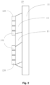
FIG. 3 is a top view of the horizontal grinder rotor. -
FIG. 4 is a front view of an embodiment of a grinding bead driving device of the horizontal grinder. -
FIG. 5 is a left view of the grinding bead driving device of the horizontal grinder. -
FIG. 6 is a particle size distribution diagram of silicon nanoparticles manufactured by the horizontal grinder of the present disclosure. - It will be appreciated that for simplicity and clarity of illustration, where appropriate, reference numerals have been repeated among the different figures to indicate corresponding or analogous elements. In addition, numerous specific details are set forth in order to provide a thorough understanding of the embodiments described herein. However, it will be understood by those of ordinary skill in the art that the embodiments described herein can be practiced without these specific details. In other instances, methods, procedures, and components have not been described in detail so as not to obscure the related relevant feature being described. The drawings are not necessarily to scale, and the proportions of certain parts may be exaggerated better illustrate details and features. The description is not to be considered as limiting the scope of the embodiments described herein.
- The term "outside" refers to a region that is beyond the outermost confines of a physical object. The term "inside" indicates that at least a portion of a region is partially contained within a boundary formed by the object. The term "substantially" is defined to essentially conforming to the particular dimension, shape or other word that substantially modifies, such that the component need not be exact. For example, substantially cylindrical means that the object resembles a cylinder, but can have one or more deviations from a true cylinder. The term "comprising" means "including, but not necessarily limited to"; it specifically indicates open-ended inclusion or membership in a so-described combination, group, series and the like. It should be noted that references to "an" or "one" embodiment in this disclosure are not necessarily to the same embodiment, and such references mean at least one.
- Referring to
Fig. 1 to Fig. 3 , a first embodiment of ahorizontal grinder rotor 10 is provided. Thehorizontal grinder rotor 10 comprises agrinding ring 11,multiple blades 12 and acenter body 13. Thegrinding ring 11, themultiple blades 12 and thecentral body 13 can be formed by 3D printing technology. The material of thehorizontal grinder rotor 10 can be high-strength plastic steel material, artificial ceramics, carbon fiber, etc. Furthermore, a cladding layer (not shown) can be provided on the surface of thehorizontal grinder rotor 10. The material of the cladding layer can be polyethylene terephthalate (PET), polytetrafluoroethylene (PTFE), polyvinylidene fluoride (PVDF), or polypropylene. - The
multiple blades 12 are located between thegrinding ring 11 and thecentral body 13. Each blade of themultiple blades 12 is arranged at intervals, thus the structure of themultiple blades 12 is hollow. Each two blades of themultiple blades 12 are in pairs, and the two blades in pairs are symmetrical with respect to thecentral body 13. A number of the blades of themultiple blades 12 is an even number, which can be two, four, six, eight or the like. A throughhole 130 is defined in the center of thecentral body 13, and twokeyways 131 are oppositely arranged on an inner wall of the throughhole 130. The throughhole 130 and the twokeyways 131 are configured to mount thehorizontal grinder rotor 10 to a grinder shaft. One ormore pins 120 are arranged on one or both sides of each blade of themultiple blades 12. The shape of thepin 120 is not limited, it can be a cylindrical protrusion, or other shapes. The number of thepins 120 can be adjusted according to the strength of the blades and the size and the volume of a horizontal grinder. There is a plurality oflatches 132 arranging on thecentral body 13 close to theblades 12. Each latch of the plurality oflatches 132 is arranged on a part of thecentral body 13 close to eachblade 12. The plurality oflatches 132 are configured to mount thehorizontal grinder rotor 10 to another rotor. - In one embodiment, there are four blades in the
multiple blades 12, and there are threepins 120 arranged on each blade of themultiple blades 12. In one embodiment, thepin 120 is a cylindrical protrusion. In one embodiment, the material of the cladding layer is PTEE, and the material can avoid production pollution. - In the
horizontal grinder rotor 10, the interval arrangement of themultiple blades 12 can increase the agitation ability of high solid content slurries. There are pins on the blades, which can increase the effective collision probability of grinding beads and increase their linear speed. The design of themultiple blades 12 symmetrically arranged in pairs relative to thecenter body 13 can be applied to vortex waterwheel, which can increase the fluidity and vortex of the slurries when the viscosity rises. Therefore, thehorizontal grinder rotor 10 can grind silicon materials with a solid content greater than 15%. Thehorizontal grinder rotor 10 can be printed with 3D printing technology, and then coated with a cladding layer, which can prolong the life. Even if a part of the cladding layer peels off, since the silicon carbon material still need to be sintered, the exfoliation of the coating material does not affect the characteristics of the silicon carbon material, thus thehorizontal grinder rotor 10 can be replaced regularly to maintain production quality. The material of thehorizontal grinder rotor 10 can be high-strength plastic steel material (such as ABS), artificial ceramics, carbon fiber, which can withstand a speed of more than 2600 rpm. - Referring to
Fig. 4 to Fig. 5 , a second embodiment of a grindingbead driving device 20 is provided. The grindingbead driving device 20 comprises arotating shaft 21 and multiple groups of thehorizontal grinder rotors 10, and multiple groups of thehorizontal grinder rotors 10 are arranged at intervals on therotating shaft 21. The multiple groups of thehorizontal grinder rotors 10 comprises at least two groups of thehorizontal grinder rotors 10, each group of thehorizontal grinder rotors 10 comprises at least twohorizontal grinder rotors 10. Two key slots are oppositely arranged on therotating shaft 21. The two key slots of therotating shaft 21 corresponds to the twokeyways 131 of thehorizontal grinder rotors 10. Thehorizontal grinder rotors 10 can be mounted on therotating shaft 21 by a key. Thehorizontal grinder rotors 10 can also be mounted on therotating shaft 21 by other methods. - In one embodiment, there are three groups of
horizontal grinder rotors 10 mounted on therotating shaft 21, each group ofhorizontal grinder rotors 10 is arranged at intervals, each group of horizontal grinder rotors comprises twohorizontal grinder rotors 10, and the twohorizontal grinder rotors 10 are fixed bylatches 132. In the projection of the twohorizontal grinder rotors 10, the blade of one horizontal grinder rotor is located between two adjacent blades of the otherhorizontal grinder rotor 10. That is, theblades 12 of the twohorizontal grinder rotors 10 are arranged at equal intervals. Thepins 120 are only arranged on one side of theblades 12 of eachhorizontal grinder rotor 10. - The multiple groups of the
horizontal grinder rotors 10 comprises at least two groups of thehorizontal grinder rotors 10, each group of thehorizontal grinder rotors 10 comprises at least twohorizontal grinder rotors 10. And the twohorizontal grinder rotors 10 are fixed bylatches 132 or other methods. The pins can only locate on one side of the blades of each horizontal grinder rotor. Furthermore, if the interference can be avoided, it is better to set pins on both sides of each blade. - A third embodiment of a horizontal grinder (not shown) is provided. The horizontal grinder comprises a grinding cylinder and the grinding
bead driving device 20. The grinding cylinder defines an inlet and an outlet. The grindingbead driving device 20 is installed in the grinding cylinder. The rotation direction of the grinding cylinder is opposite to the rotation direction of therotating shaft 21 in the grindingbead driving device 20. In one embodiment, the pins are only located on the horizontal grinder rotor close to the outlet, and the pins are respectively arranged on a side of the horizontal grinder rotor close to the outlet. - Since the 3D printing time of each horizontal grinder rotor does not exceed twenty-four hours, the cost of the
horizontal grinder rotor 10 can be greatly reduced. - A fourth embodiment of a method of making a silicon-carbon composite material is provided. The method of making a silicon-carbon composite material is carried out in the above horizontal grinder. The method comprises following steps: adding grinding beads to the horizontal grinder; adding semiconductor-grade silicon as a silicon source, wherein the size of the semiconductor-grade silicon is greater than ten microns; adding a protective solvent, wherein the protective solvent can be an alcohol such as diethylene glycol or an oil; then grinding the semiconductor-grade silicon to obtain nanoscale silicon particles, wherein the solid content of the nanoscale silicon particles is greater than 15%; then adding carbon sources for homogeneous coating on a surface of the nanoscale silicon particles to obtain the nanoscale silicon-carbon composite material, wherein the carbon sources can be graphite, graphene, carbon black, pitch, carbon nanotubes, etc. Furthermore, a polymer material can be introduced into the carbon sources to increase the viscosity of the carbon sources and make it easy for the carbon sources to coat the nanoscale silicon particles. The polymer material can be polyvinylpyrrolidone (PVP), N-allyl-(2-ethyl xanthate) propionamide (NAPA), dimethylformamide (DMF), or carboxymethyl cellulose (CMC) etc.
- Referring to
Fig.6 , a horizontal axis represents the particle size, a right vertical axis represents a cumulative percentage, and a left vertical axis represents a particle content of the corresponding particle size.Figure 6 shows that a horizontal grinder can obtain silicon nanoparticles with concentrated particle size, with a span of less than 0.8 calculated by the following formula.
- The method of making a silicon-carbon composite material can realize the self-assembly stacking of silicon-carbon composite materials through grinding, which can improve the electrochemical of the silicon-carbon composite materials. The grinding bead driving device can evenly stir the slurry, increase the frequency of effective collision of grinding beads, and improve the grinding efficiency. While the specific surface area of nano-silicon continues to increase, the grinding bead driving device can still maintain the smoothness of the slurry circulation, and make the silicon particle size reach a set particle size. At the same time, the rotor can be obtained with 3D printing technology. Therefore, the rotor can be used as a consumable for regular replacement, which is beneficial to reduce inventory costs.
- The embodiments shown and described above are only examples. Even though numerous characteristics and advantages of the present technology have been set forth in the foregoing description, together with details of the structure and function of the present disclosure, the disclosure is illustrative only, and changes may be made in the detail, including in matters of shape, size and arrangement of the parts within the principles of the present disclosure up to, and including, the full extent established by the broad general meaning of the terms used in the claims.
- The above embodiments are only used to illustrate the technical solutions of the present application rather than limitations. Although the present application has been described in detail with reference to the above preferred embodiments, one of ordinary skill in the art should understand that the technical solutions of the present application may be modified or equivalently replaced without departing from the spirit and scope of the technical solutions of the present application.
Claims (15)
- A horizontal grinder rotor comprises:a grinding ring;multiple blades; anda center body;wherein the grinding ring, the multiple blades and the central body are formed by 3D printing, the multiple blades are located between the grinding ring and the central body, the multiple blades are arranged at intervals, the multiple blades are arranged in pairs and symmetrical with respect to the central body, the horizontal grinder rotor further comprises one or more pins, the one or more pins are provided on at least one side of each of the multiple blades.
- The horizontal grinder rotor according to claim 1, further comprising a cladding layer on a surface of the horizontal grinder rotor.
- The horizontal grinder rotor according to claim 2, wherein a material of the cladding layer is selected from a group consisting of polyethylene terephthalate, polytetrafluoroethylene, polyvinylidene fluoride, and polypropylene.
- The horizontal grinder rotor according to any one of claims 1-3, wherein a shape of the pins is a cylindrical protrusion.
- The horizontal grinder rotor according to any one of claims 1-3, wherein the central body is provided with a through hole, and at least one keyway is formed on an inner wall of the through hole.
- The horizontal grinder rotor according to claim 1, wherein a material of the horizontal grinder rotor is selected from a group consisting of plastic steel material, artificial ceramics, and carbon fiber.
- The horizontal grinder rotor according to any one of claims 1-6, further comprising a plurality of latches, and each of latches is arranged on a part of the central body close to each of the multiple blades.
- The horizontal grinder rotor according to claim 1, wherein a number of multiple blades is an even number.
- A grinding bead driving device comprises a rotating shaft and multiple groups of horizontal grinder rotors according to any one of claims 1-8, wherein the multiple groups of horizontal grinder rotors are arranged at intervals on the rotating shaft, each group of horizontal grinder rotors comprises at least two horizontal grinder rotors.
- The grinding bead driving device according to claim 9, wherein each of the multiple blades of each group of horizontal grinder rotors is arranged at equal intervals.
- The grinding bead driving device according to any one of claims 9-10, wherein each of the horizontal grinder rotor is mounted on the rotating shaft by a key.
- The grinding bead driving device according to any one of claims 9-10, wherein two adjacent horizontal grinder rotors are fixed by latches.
- A horizontal grinder comprises:
a grinding cylinder and a grinding bead driving device, wherein the grinding bead driving device is installed in the grinding cylinder, the grinding bead driving device comprises a rotating shaft and multiple groups of horizontal grinder rotors according to claims 1-12, wherein a first rotation direction of the grinding cylinder is opposite to a second rotation direction of the rotating shaft of the grinding bead driving device. - The horizontal grinder according to claim 13, wherein the multiple groups of horizontal grinder rotors comprise at least two groups of horizontal grinder rotors, each group of horizontal grinder rotors comprises at least two horizontal grinder rotors.
- The horizontal grinder according to claim 13, wherein the grinding cylinder is provided with an inlet and an outlet, and the pins are respectively arranged on a side of the horizontal grinder rotor close to the outlet.
Applications Claiming Priority (1)
| Application Number | Priority Date | Filing Date | Title |
|---|---|---|---|
| CN202210811342.6A CN117414911A (en) | 2022-07-11 | 2022-07-11 | Horizontal grinding machine rotor, grinding bead drive and horizontal grinding machine |
Publications (1)
| Publication Number | Publication Date |
|---|---|
| EP4306218A1 true EP4306218A1 (en) | 2024-01-17 |
Family
ID=89159412
Family Applications (1)
| Application Number | Title | Priority Date | Filing Date |
|---|---|---|---|
| EP23184523.1A Pending EP4306218A1 (en) | 2022-07-11 | 2023-07-10 | Horizontal grinder rotor, grinding bead driving device and horizontal grinder |
Country Status (3)
| Country | Link |
|---|---|
| US (1) | US20240009676A1 (en) |
| EP (1) | EP4306218A1 (en) |
| CN (1) | CN117414911A (en) |
Citations (2)
| Publication number | Priority date | Publication date | Assignee | Title |
|---|---|---|---|---|
| DE2140199B1 (en) * | 1971-08-11 | 1973-01-18 | Draiswerke Gmbh, 6800 Mannheim | RUHRWERKSMÜHLE |
| US20030209618A1 (en) * | 2000-01-10 | 2003-11-13 | Sneeringer John R | Fine media mill with improved disc |
Family Cites Families (15)
| Publication number | Priority date | Publication date | Assignee | Title |
|---|---|---|---|---|
| KR20090128710A (en) * | 2008-06-11 | 2009-12-16 | 문영석 | Manure drying system |
| CN204816716U (en) * | 2015-07-01 | 2015-12-02 | 苏州中亚油墨有限公司 | Novel sand mill turbine disc |
| EP3311921B1 (en) * | 2016-10-18 | 2018-09-26 | Willy A. Bachofen AG | Agitator ball mill |
| CN206613562U (en) * | 2017-03-20 | 2017-11-07 | 河北赛丰生物科技有限公司 | Pesticides additive agent sand mill |
| DE202017107050U1 (en) * | 2017-05-04 | 2018-08-07 | Retsch Gmbh | rotor mill |
| CN109289996A (en) * | 2017-07-25 | 2019-02-01 | 夏青 | A kind of sand mill for Chemical Manufacture |
| CN209715270U (en) * | 2019-01-21 | 2019-12-03 | 浙江理工大学 | A kind of agitation grinding device |
| CN209809971U (en) * | 2019-04-18 | 2019-12-20 | 温在友 | Material smashing and mixing device |
| BR112022021959A2 (en) * | 2020-04-30 | 2022-12-13 | Vectis Pty Ltd as trustee for JJB Trust | GRIND MILL ROTOR |
| CN212596099U (en) * | 2020-06-15 | 2021-02-26 | 东莞市康博机械有限公司 | An alloy nanorod pin sand mill |
| CN213315346U (en) * | 2020-08-05 | 2021-06-01 | 上海易勒机电设备有限公司 | Turbine sand mill |
| CN113019588B (en) * | 2021-03-05 | 2021-12-14 | 江南大学 | Gap-adjustable conical grinding device for preparing nano powder |
| CN215087682U (en) * | 2021-04-07 | 2021-12-10 | 重庆汉宝水性漆有限公司 | Horizontal sand mill of waterproof coating |
| CN216605467U (en) * | 2021-11-15 | 2022-05-27 | 河北金坤工程材料有限公司 | Horizontal type conical sand mill with cooling mechanism |
| TWI845983B (en) * | 2022-07-11 | 2024-06-21 | 鴻海精密工業股份有限公司 | Horizontal grinding machine rotor,grinding bead driving device and horizontal grinding machine |
-
2022
- 2022-07-11 CN CN202210811342.6A patent/CN117414911A/en active Pending
-
2023
- 2023-07-10 US US18/219,744 patent/US20240009676A1/en active Pending
- 2023-07-10 EP EP23184523.1A patent/EP4306218A1/en active Pending
Patent Citations (2)
| Publication number | Priority date | Publication date | Assignee | Title |
|---|---|---|---|---|
| DE2140199B1 (en) * | 1971-08-11 | 1973-01-18 | Draiswerke Gmbh, 6800 Mannheim | RUHRWERKSMÜHLE |
| US20030209618A1 (en) * | 2000-01-10 | 2003-11-13 | Sneeringer John R | Fine media mill with improved disc |
Also Published As
| Publication number | Publication date |
|---|---|
| CN117414911A (en) | 2024-01-19 |
| US20240009676A1 (en) | 2024-01-11 |
Similar Documents
| Publication | Publication Date | Title |
|---|---|---|
| CN1697215A (en) | Lithium-ion battery composite carbon negative electrode material and preparation method thereof | |
| CN109103438B (en) | Core-shell structure negative electrode material for lithium ion battery and preparation method thereof | |
| CN103682287A (en) | Lithium ion battery silicon-based composite anode material, preparation method thereof and battery | |
| CN111348647B (en) | Silicon-carbon composite material with multi-layer coating structure and preparation method thereof | |
| US10651461B2 (en) | Lithium battery cathode | |
| CN115954447A (en) | A kind of hydrophobic polymer-coated modified sodium electrode material, preparation method and battery | |
| US20220149340A1 (en) | Anode having high top layer sphericity | |
| CN112121660A (en) | A kind of compounding method of positive electrode slurry of lithium ion battery | |
| CN103474637A (en) | Lithium ion battery anode material and preparation method thereof | |
| Yang et al. | Properties of silicon nanoparticles prepared by pulse discharge and ball milling | |
| KR102731189B1 (en) | battery electrode manufacturing device | |
| CN109904373B (en) | Lithium ion battery, lithium ion battery isolating membrane and preparation method thereof | |
| TWI845983B (en) | Horizontal grinding machine rotor,grinding bead driving device and horizontal grinding machine | |
| US20240009676A1 (en) | Horizontal grinder rotor, grinding bead driving device and horizontal grinder | |
| CN113140713B (en) | A LiFePO4/C coated ternary positive electrode material and its preparation method and use | |
| CN112549528A (en) | Preparation method of optimized extrusion type 3D printing electrode | |
| CN1558458A (en) | Graphite powder for negative electrode of lithium ion secondary cell and manufacturing method thereof | |
| CN121103216A (en) | Mixing equipment for uniform dispersion in graphite anode production | |
| CN119994069B (en) | A kind of soft ball milling coated modified particles and preparation method and application thereof | |
| CN1635650A (en) | A kind of negative electrode graphite material of lithium ion secondary battery and preparation method thereof | |
| CN1815779A (en) | Method for making lithium ion cell positive electrode sheet, positive-electrode sheet and lithium ion cell | |
| CN111916688B (en) | Lithium cobaltate composite positive electrode material and preparation method thereof | |
| CN106450465A (en) | Preparation method of slurry of lithium-ion battery | |
| CN218902132U (en) | Preparation device for silicon-carbon anode material of lithium ion battery | |
| EP4620560A1 (en) | Slurry mixing apparatus |
Legal Events
| Date | Code | Title | Description |
|---|---|---|---|
| PUAI | Public reference made under article 153(3) epc to a published international application that has entered the european phase |
Free format text: ORIGINAL CODE: 0009012 |
|
| STAA | Information on the status of an ep patent application or granted ep patent |
Free format text: STATUS: THE APPLICATION HAS BEEN PUBLISHED |
|
| AK | Designated contracting states |
Kind code of ref document: A1 Designated state(s): AL AT BE BG CH CY CZ DE DK EE ES FI FR GB GR HR HU IE IS IT LI LT LU LV MC ME MK MT NL NO PL PT RO RS SE SI SK SM TR |
|
| STAA | Information on the status of an ep patent application or granted ep patent |
Free format text: STATUS: REQUEST FOR EXAMINATION WAS MADE |
|
| 17P | Request for examination filed |
Effective date: 20240320 |
|
| RBV | Designated contracting states (corrected) |
Designated state(s): AL AT BE BG CH CY CZ DE DK EE ES FI FR GB GR HR HU IE IS IT LI LT LU LV MC ME MK MT NL NO PL PT RO RS SE SI SK SM TR |