EP4306211A1 - Device for holding a container, insert for such device and method for manufacturing such device and insert - Google Patents
Device for holding a container, insert for such device and method for manufacturing such device and insert Download PDFInfo
- Publication number
- EP4306211A1 EP4306211A1 EP22184543.1A EP22184543A EP4306211A1 EP 4306211 A1 EP4306211 A1 EP 4306211A1 EP 22184543 A EP22184543 A EP 22184543A EP 4306211 A1 EP4306211 A1 EP 4306211A1
- Authority
- EP
- European Patent Office
- Prior art keywords
- insert
- container
- opening
- flexible portions
- containers
- Prior art date
- Legal status (The legal status is an assumption and is not a legal conclusion. Google has not performed a legal analysis and makes no representation as to the accuracy of the status listed.)
- Withdrawn
Links
Images




Classifications
-
- B—PERFORMING OPERATIONS; TRANSPORTING
- B01—PHYSICAL OR CHEMICAL PROCESSES OR APPARATUS IN GENERAL
- B01L—CHEMICAL OR PHYSICAL LABORATORY APPARATUS FOR GENERAL USE
- B01L9/00—Supporting devices; Holding devices
- B01L9/06—Test-tube stands; Test-tube holders
-
- B—PERFORMING OPERATIONS; TRANSPORTING
- B01—PHYSICAL OR CHEMICAL PROCESSES OR APPARATUS IN GENERAL
- B01L—CHEMICAL OR PHYSICAL LABORATORY APPARATUS FOR GENERAL USE
- B01L3/00—Containers or dishes for laboratory use, e.g. laboratory glassware; Droppers
- B01L3/50—Containers for the purpose of retaining a material to be analysed, e.g. test tubes
- B01L3/508—Rigid containers without fluid transport within
- B01L3/5085—Rigid containers without fluid transport within for multiple samples, e.g. microtitration plates
-
- B—PERFORMING OPERATIONS; TRANSPORTING
- B01—PHYSICAL OR CHEMICAL PROCESSES OR APPARATUS IN GENERAL
- B01L—CHEMICAL OR PHYSICAL LABORATORY APPARATUS FOR GENERAL USE
- B01L2200/00—Solutions for specific problems relating to chemical or physical laboratory apparatus
- B01L2200/02—Adapting objects or devices to another
- B01L2200/021—Adjust spacings in an array of wells, pipettes or holders, format transfer between arrays of different size or geometry
-
- B—PERFORMING OPERATIONS; TRANSPORTING
- B01—PHYSICAL OR CHEMICAL PROCESSES OR APPARATUS IN GENERAL
- B01L—CHEMICAL OR PHYSICAL LABORATORY APPARATUS FOR GENERAL USE
- B01L2200/00—Solutions for specific problems relating to chemical or physical laboratory apparatus
- B01L2200/02—Adapting objects or devices to another
- B01L2200/023—Adapting objects or devices to another adapted for different sizes of tubes, tips or container
-
- B—PERFORMING OPERATIONS; TRANSPORTING
- B01—PHYSICAL OR CHEMICAL PROCESSES OR APPARATUS IN GENERAL
- B01L—CHEMICAL OR PHYSICAL LABORATORY APPARATUS FOR GENERAL USE
- B01L2300/00—Additional constructional details
- B01L2300/06—Auxiliary integrated devices, integrated components
- B01L2300/0609—Holders integrated in container to position an object
-
- B—PERFORMING OPERATIONS; TRANSPORTING
- B01—PHYSICAL OR CHEMICAL PROCESSES OR APPARATUS IN GENERAL
- B01L—CHEMICAL OR PHYSICAL LABORATORY APPARATUS FOR GENERAL USE
- B01L2300/00—Additional constructional details
- B01L2300/08—Geometry, shape and general structure
- B01L2300/0809—Geometry, shape and general structure rectangular shaped
- B01L2300/0829—Multi-well plates; Microtitration plates
-
- B—PERFORMING OPERATIONS; TRANSPORTING
- B01—PHYSICAL OR CHEMICAL PROCESSES OR APPARATUS IN GENERAL
- B01L—CHEMICAL OR PHYSICAL LABORATORY APPARATUS FOR GENERAL USE
- B01L2300/00—Additional constructional details
- B01L2300/12—Specific details about materials
- B01L2300/123—Flexible; Elastomeric
Definitions
- the present invention relates to a device for holding a container, as well as to an insert for such device and a method for manufacturing such device and insert.
- the invention relates to a device of the type which comprises a body and an opening in said body for receiving the container.
- Such device is known per se. It has an opening configured to receive a container with a particular size and/or shape. However, when a container with a different size or shape needs to be held by the device, e.g. a smaller or larger container, or a square container instead of a circular container, this device is no longer suitable. A new device has to be manufactured with an opening that is adapted to receive the smaller or larger container, or the square container. Hence, known devices have a limited container compatibility. They are not universally applicable.
- the invention aims to increase the universality of a device for holding a container.
- the invention seeks to eliminate the need for a specifically configured device to obtain compatibility with a certain container.
- the present invention according to a first aspect relates to a device of the above-mentioned type, with the characteristic that the device comprises an insert insertable in the opening.
- the insert may allow to adapt the opening to the container, in particular the size and/or shape of the container.
- the insert may allow to grip the container, irrespective or substantially irrespective of the size, shape and/or other characteristics of the container.
- the opening is able to receive containers having different characteristics, such as a different size and/or shape.
- the device is compatible with a broad range of containers. For example, when smaller or larger containers need to be held, there is no longer a need to manufacture a new device.
- the device of the present invention is more universal than the known device described above.
- the insert is flexible.
- the insert may comprise one or more flexible portions configured to flex when the container is received in the opening.
- the opening can be adapted to the received container, in particular to the size and/or shape of the container.
- the term "flexing" or “flexible” is used to indicate that something is able to move, deform and/or bend, preferably in an elastic manner.
- the insert may comprise a slit or cut pattern.
- This slit or cut pattern may comprise one or more slits or cuts.
- the slits or cuts may be intersecting.
- the one or more slits or cuts may define the one or more flexible portions. The flexibility of the insert may be at least partially obtained due to the provision of the slit or cut pattern, or the one or more slits or cuts.
- the one or more flexible portions may comprise one or more angular segments.
- the one or more angular segments, or more generally the one or more flexible portions, may be inwardly directed. This means that they are directed to the centre of the opening.
- the insert comprises between four and eight flexible portions, for example in the form of angular segments. More preferably, the insert comprises between five and seven flexible portions. Most preferably, the insert comprises six flexible portions.
- the one or more flexible portions may be oriented horizontally, or substantially horizontally when the insert is free from container, i.e. when no container is introduced in the insert. Such horizontal orientation, where the one or more flexible portions are parallel, or substantially parallel to an upper surface, or main plane of the device, or the body of the device, allows for a compact design of the insert.
- the one or more flexible portions have a thickness lying between 0.3 millimetres (mm) and 1mm, between 0.4mm and 0.9mm, between 0.5mm and 0.8mm, or between 0.6mm and 0.7mm.
- mm millimetres
- the inventors have found that such thickness provides a flexibility that is most compatible with a broad range of containers.
- the insert may comprise guiding means or guiding parts to guide the container in the opening.
- the insert may have oblique walls forming said guiding means or guiding parts.
- the insert may also form a funnel.
- at least one and preferably all of the one or more flexible portions of the insert may be directed downwards, when the insert is free from container, i.e. when no container is introduced in the insert. Such downward orientation assists in guiding the container in the opening and thus acts as guiding means or guiding parts.
- the at least one flexible portion may be directed downwards slightly, such as between 1 and 15 degrees with respect to a horizontal plane, or an upper surface or a main plane of the device, or the body of the device, or between 1 and 10 degrees, or between 1 and 5 degrees.
- the insert is configured to grip the container when the container is received in the opening.
- the container can be held firmly in position by the device, and a risk of the container falling out of the device can be reduced or even eliminated.
- said gripping action may be provided by the one or more flexible portions willing to return to their initial rest position due to an elastic restoring force.
- the insert may be fixedly insertable in the opening. In this way, it is prevented or at least counteracted that the insert comes loose from the opening, for example when moving the container out of the opening.
- the insert may be snappable or clickable in the opening.
- the insert is shaped so as to conform to the opening.
- the insert may be circular, or substantially circular.
- the insert may have any shape or size.
- the insert can be made of any material.
- it can be made of a polymer material, a plastic material or a rubber material.
- it is made of a thermoplastic elastomer (TPE).
- TPE thermoplastic elastomer
- a thermoplastic elastomer (TPE) is also called a thermoplastic rubber. It is a class of copolymers that comprise materials with both thermoplastic and elastomeric properties. Such type of materials is flexible so as to allow the insert to flex easily, and also does not result into too much friction allowing the container to slide along the insert easily.
- Any type of TPE can be used.
- the Shore D hardness lies between 22D and 32D, more preferably between 24D and 30D, most preferably is about 27D.
- the Shore A hardness lies between 80A and 90A, more preferably between 82A and 88A, most preferably is about 85A.
- the insert can be made using any type of manufacturing technique.
- the insert is made using extrusion or injection moulding. This is a suitable technique, especially when the insert is made of a plastic material, a polymer material or a rubber material.
- the body of the device may be made of any material.
- the body of the device can be made of steel, a plastic material, a polymer material, a rubber material or aluminium.
- the body of the device is made of aluminium, because it is strong but also relatively light in weight.
- the device may be height-adjustable.
- the height of the opening may be adjustable.
- the device can be compatible not only with containers of different sizes and/or shapes, but also with containers of different heights.
- the body of the device may be formed by a frame.
- the body of the device may contain a first body layer containing the opening and a second body layer below the first body layer, the second body layer containing a second opening.
- the second opening may be aligned with the opening of the first body layer, so that they are intended to receive the same container.
- the height may be adjusted by adjusting the relative distance between the first body layer and the second body layer, such as by increasing or decreasing said distance.
- the device may be configured to hold multiple containers.
- the device may comprise multiple openings to receive the respective containers.
- the device may be configured to hold ninety-six containers, such as ninety-six tubes or sample storage tubes, and hereto may comprise ninety-six openings in the body to receive the respective containers.
- these openings may be positioned in rows, such as staggered rows.
- the containers that are held by the device may be easily gripped by automatic or robotic grippers, which are typically three-armed.
- the invention is not limited to such staggered configuration. Any configuration may be used.
- the device may comprise multiple inserts as described herein which are insertable in the respective openings. Then, each insert may be sized or shaped to be inserted into one opening, or to fit in one opening. In an alternative embodiment, an insert may be provided that is shaped or sized to cooperate with, or be insertable in more than one of the multiple openings. In such case, instead of multiple separate inserts, one insert may be provided that cooperates with a plurality of openings. More particularly, the insert may comprise one or more flexible portions at locations where a cooperating opening is present.
- an insert is provided.
- the insert may be a separate piece.
- the insert may be made of a different material than the body of the device. This is advantageous, because the body and the insert may each be made from a material that is suitable for the intended purpose.
- the body needs to provide sufficient strength, because it has to carry the container, or multiple containers. Therefore, it is preferably made of steel or, more preferably, aluminium.
- the insert may be flexible. Therefore, it is preferably made of a plastic material, a polymer material or a rubber material or, more preferably, a thermoplastic elastomer.
- the parts or portions of the insert may be made in one piece with the body of the device.
- the present invention according to a second aspect relates to a device for holding a container, comprising a body and an opening in the body for receiving the container, with the characteristic that the opening is adaptable, more particularly adaptable to the size and/or shape of the container.
- the opening is provided with one or more flexible portions configured to flex when the container is received in the opening.
- the device according to the second aspect may show one or more features described in relation to the device according to the first aspect, without being limited to an insert. All features described in relation to the insert of the device of the first aspect may be applied, individually or in any combination, to the device according to the second aspect, but then in a one-piece configuration, such as in one piece with the device, or the body of the device.
- the present invention may be advantageously used to devices such as racks, tube racks, plate carriers or multi-well plates. These devices may be used for the purpose of automated or robotic handling systems, such as automated or robotic liquid handling systems.
- the present invention may be applied in the area of molecular diagnostics, such as in the area of extraction DNA/RNA isolation technology. The present invention is however not limited to such application and may be applied in any context.
- the container may be a tube, such as a sample storage tube.
- the container may be filled or fillable with a liquid, a sample or other reagent.
- the device may be equipped with a barcode.
- the present invention also relates to an insert for a device as described herein, including a device according to the first aspect or second aspect of the present invention.
- the present invention also relates to the use of an insert in a device as described herein, including a device according to the first aspect or second aspect of the present invention.
- the present invention relates to a method comprising the step of manufacturing a device or insert as described herein.
- intervals defined herein include the end points of the interval.
- Figure 1 shows a device 1 according to the invention. It is configured to hold multiple containers 2, but only one container is shown.
- the device 1 is a tube rack and the containers 2 are sample storage tubes.
- the containers 2 may store a liquid or other sample or reagent.
- the device 1 may be used to hold containers 2 in automated or robotic handling systems, such as automated or robotic liquid handling systems.
- containers or their content may be transferred using robotic grippers, robotic pipetting systems or other handling mechanisms.
- Automated or robotic handling systems may use automated or robotic instruments that run analyses or assays. They are "automatic", because they do not require input or substantial input from a lab technician.
- the device 1 may be applied in the area of molecular diagnostics, such as in the area of extraction DNA/RNA isolation technology.
- the device 1 comprises a body 3, such as a frame.
- the body 3 is made of aluminium.
- the device 1 comprises multiple openings 4 in the body 3 to receive the respective containers 2.
- the openings 4 are circular, but may have any shape.
- the device 1 is configured to hold ninety-six containers 2. Thereto, the device 1 comprises ninety-six openings 4 to receive the respective containers 2.
- the multiple openings 4 are arranged in eight rows, each row containing twelve openings 4.
- the rows of openings 4 are positioned in a staggered relationship. Such positioning allows for easy gripping of the containers 2 by a robotic gripper, which is typically three-armed.
- the device 1 may contain a marking indicative of the position of the container 2. Such marking may be provided adjacent to each opening 4. The marking is not shown in the figure.
- the device 1 also comprises an insert 5 insertable in the opening 4.
- the insert 5 conforms to the shape of the opening 4 and is circular, but in general may have any shape.
- the device 1 comprises multiple inserts 5 to insert in the respective openings 4, but only one insert is shown in figure 1 .
- the insert 5 may be fixedly insertable in the opening 4.
- the insert 5 may be snappable or clickable in the opening 4.
- the insert 5 allows to adapt the opening 4, more particularly to the size and/or shape of the container 2 receivable in the opening 4. It allows the opening 4 to hold the container 2 firmly, irrespective or substantially irrespective of the size and/or shape of the container 2.
- the working principle of the insert 5 is explained in more detail in relation to figures 3a and 3b .
- Figure 1 shows the device 1 in exploded view.
- the container 2 and the insert 5 are in a non-inserted condition.
- Figure 2a shows the device 1 in non-exploded view.
- the insert 5 is inserted in the opening 4. More particularly, multiple inserts 5 are shown inserted in the respective openings 4.
- the containers 2 are not shown.
- Figure 2b shows the device 1 of figure 2a , but in a top view.
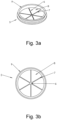
- Figure 3a shows the insert 5 of the device 1.
- the insert 5 is shown in a non-inserted condition, i.e. it is not inserted in the opening 4. Also, the container 2 is not inserted in the insert 5.
- the insert 5 is shown in a relaxed or rest condition.
- the insert 5 is made of a thermoplastic elastomer (TPE). It may be manufactured using extrusion, injection moulding or any other suitable technique.
- TPE thermoplastic elastomer
- the insert 5 is provided with a slit or cut pattern 6.
- the slit or cut pattern 6 includes more than one slit or cut 7, which in the example are intersecting.
- the slit or cut pattern 6 defines more than one flexible portion 8, in this case six flexible portions 8.
- the flexible portions 8 are inwardly directed. This means that they are directed to the centre of the opening 4. They form angular segments.
- the flexible portions 8 are oriented horizontally, or substantially horizontally. This means that the flexible portions are parallel, or substantially parallel to the upper surface of the body 3. This allows for a compact design of the insert 5.
- the flexible portions 8 may be directed downwards, i.e. towards the bottom of the device 1. They may be directed downwards slightly, such as between 1 and 15 degrees with respect to a horizontal plane, or between 1 and 10 degrees, or between 1 and 5 degrees. Such orientation acts as a guiding means or guiding parts, guiding the container 2 in the opening 4.
- the flexible portions 8 are configured to flex when the container 2 is received in the opening 4. For example, they may move, bend and/or deform, preferably in an elastic manner. In this example, the flexible portions 8 will bend downwards elastically, as shown in figures 4 and 5 . With this bending action, the opening 4 is adapted to the size and/or shape of the container 2. For example, the larger the container 2 in width, the more the flexible portions 8 will bend.
- the flexible portions 8 With the bending action, the flexible portions 8 also hold the container 2 firmly. They grip the container 2. More particularly, the flexible portions 8 want to return to their original rest position or orientation. This is due to the elastic restoring force. Thereby, they exert a force on the container 2, preferably clamping the container 2.
- one or more flexible portions 8 may be coated with a frictional enhancement material, such as an adhesive, to increase their tackiness.
- the insert 5 also comprises an upstanding rim 9 along its circumference.
- Figure 3b shows the insert 5 of figure 3a , but in a top view.
- Figure 4 shows the device 1 of figure 1 in a side view.
- the device 1 is shown in a condition where the insert 5 is inserted in the opening 4, and the container 2 is received in the opening 4.
- the body 3 of the device 1 comprises a first body layer containing the openings 4, and a second body layer containing openings 10.
- the openings 10 are located below and aligned with the respective openings 4.
- the device 1 also comprises multiple inserts 11 insertable into the respective openings 10.
- the inserts 11 are identical to the inserts 5.
- the first body layer is located at a distance H1 from the second body layer. This distance is adjustable, by which the device 1 is height-adjustable. More particularly, the first body layer can be displaced in a height direction.
- figure 5 also shows a side view of the device of figure 1 , but with the first body layer lying at a larger distance H2 from the second body layer. In this configuration, the device 1 can hold larger containers in length.
- Figures 4 and 5 also show a closer view of the insert 5 in a condition where it receives the container 2. As shown in these figures, the flexible portions 8 are bent downwards in this condition.
- the flexible portions 8 have a thickness T lying between 0.6 and 0.7mm.
Landscapes
- Health & Medical Sciences (AREA)
- Chemical & Material Sciences (AREA)
- Clinical Laboratory Science (AREA)
- Chemical Kinetics & Catalysis (AREA)
- Analytical Chemistry (AREA)
- General Health & Medical Sciences (AREA)
- Hematology (AREA)
- Details Of Rigid Or Semi-Rigid Containers (AREA)
Abstract
Device (1) for holding a container (2), comprising a body (3) and an opening (4) in said body (3) for receiving the container (2), characterized in that the device (1) also comprises an insert (5) insertable in the opening (4).
Description
- The present invention relates to a device for holding a container, as well as to an insert for such device and a method for manufacturing such device and insert.
- More particularly, the invention relates to a device of the type which comprises a body and an opening in said body for receiving the container.
- Such device is known per se. It has an opening configured to receive a container with a particular size and/or shape. However, when a container with a different size or shape needs to be held by the device, e.g. a smaller or larger container, or a square container instead of a circular container, this device is no longer suitable. A new device has to be manufactured with an opening that is adapted to receive the smaller or larger container, or the square container. Hence, known devices have a limited container compatibility. They are not universally applicable.
- It is an objective of the present invention to provide a device that solves the above or other problems with known devices. More particularly, the invention aims to increase the universality of a device for holding a container. For example, the invention seeks to eliminate the need for a specifically configured device to obtain compatibility with a certain container.
- Thereto, the present invention according to a first aspect relates to a device of the above-mentioned type, with the characteristic that the device comprises an insert insertable in the opening. The insert may allow to adapt the opening to the container, in particular the size and/or shape of the container. The insert may allow to grip the container, irrespective or substantially irrespective of the size, shape and/or other characteristics of the container. With the insert, the opening is able to receive containers having different characteristics, such as a different size and/or shape. As a result, the device is compatible with a broad range of containers. For example, when smaller or larger containers need to be held, there is no longer a need to manufacture a new device. The device of the present invention is more universal than the known device described above.
- Preferably, the insert is flexible. For example, the insert may comprise one or more flexible portions configured to flex when the container is received in the opening. By flexing the insert, the opening can be adapted to the received container, in particular to the size and/or shape of the container. In the context of the present invention, the term "flexing" or "flexible" is used to indicate that something is able to move, deform and/or bend, preferably in an elastic manner.
- In a practical embodiment, the insert may comprise a slit or cut pattern. This slit or cut pattern may comprise one or more slits or cuts. The slits or cuts may be intersecting. The one or more slits or cuts may define the one or more flexible portions. The flexibility of the insert may be at least partially obtained due to the provision of the slit or cut pattern, or the one or more slits or cuts.
- The one or more flexible portions may comprise one or more angular segments. The one or more angular segments, or more generally the one or more flexible portions, may be inwardly directed. This means that they are directed to the centre of the opening.
- Preferably, the insert comprises between four and eight flexible portions, for example in the form of angular segments. More preferably, the insert comprises between five and seven flexible portions. Most preferably, the insert comprises six flexible portions.
- The one or more flexible portions may be oriented horizontally, or substantially horizontally when the insert is free from container, i.e. when no container is introduced in the insert. Such horizontal orientation, where the one or more flexible portions are parallel, or substantially parallel to an upper surface, or main plane of the device, or the body of the device, allows for a compact design of the insert.
- Preferably, the one or more flexible portions have a thickness lying between 0.3 millimetres (mm) and 1mm, between 0.4mm and 0.9mm, between 0.5mm and 0.8mm, or between 0.6mm and 0.7mm. The inventors have found that such thickness provides a flexibility that is most compatible with a broad range of containers.
- The insert may comprise guiding means or guiding parts to guide the container in the opening. For example, the insert may have oblique walls forming said guiding means or guiding parts. The insert may also form a funnel. In a particular embodiment, at least one and preferably all of the one or more flexible portions of the insert may be directed downwards, when the insert is free from container, i.e. when no container is introduced in the insert. Such downward orientation assists in guiding the container in the opening and thus acts as guiding means or guiding parts. The at least one flexible portion may be directed downwards slightly, such as between 1 and 15 degrees with respect to a horizontal plane, or an upper surface or a main plane of the device, or the body of the device, or between 1 and 10 degrees, or between 1 and 5 degrees.
- Preferably, the insert is configured to grip the container when the container is received in the opening. With this gripping action, the container can be held firmly in position by the device, and a risk of the container falling out of the device can be reduced or even eliminated. For example, said gripping action may be provided by the one or more flexible portions willing to return to their initial rest position due to an elastic restoring force.
- The insert may be fixedly insertable in the opening. In this way, it is prevented or at least counteracted that the insert comes loose from the opening, for example when moving the container out of the opening. For example, the insert may be snappable or clickable in the opening.
- Preferably, the insert is shaped so as to conform to the opening. For example, the insert may be circular, or substantially circular. In general, the insert may have any shape or size.
- The insert can be made of any material. For example, it can be made of a polymer material, a plastic material or a rubber material. Preferably, it is made of a thermoplastic elastomer (TPE). A thermoplastic elastomer (TPE) is also called a thermoplastic rubber. It is a class of copolymers that comprise materials with both thermoplastic and elastomeric properties. Such type of materials is flexible so as to allow the insert to flex easily, and also does not result into too much friction allowing the container to slide along the insert easily. Any type of TPE can be used. Preferably, the Shore D hardness lies between 22D and 32D, more preferably between 24D and 30D, most preferably is about 27D. Preferably, the Shore A hardness lies between 80A and 90A, more preferably between 82A and 88A, most preferably is about 85A.
- The insert can be made using any type of manufacturing technique. Preferably, the insert is made using extrusion or injection moulding. This is a suitable technique, especially when the insert is made of a plastic material, a polymer material or a rubber material.
- The body of the device may be made of any material. For example, the body of the device can be made of steel, a plastic material, a polymer material, a rubber material or aluminium. Preferably, the body of the device is made of aluminium, because it is strong but also relatively light in weight.
- The device may be height-adjustable. In particular, the height of the opening may be adjustable. In this way, the device can be compatible not only with containers of different sizes and/or shapes, but also with containers of different heights.
- The body of the device may be formed by a frame.
- In a particular embodiment, the body of the device may contain a first body layer containing the opening and a second body layer below the first body layer, the second body layer containing a second opening. The second opening may be aligned with the opening of the first body layer, so that they are intended to receive the same container. More particularly in the embodiment where the device is height-adjustable, such body configuration may be advantageous. In particular, the height may be adjusted by adjusting the relative distance between the first body layer and the second body layer, such as by increasing or decreasing said distance.
- The device may be configured to hold multiple containers. In such case, the device may comprise multiple openings to receive the respective containers. For example, the device may be configured to hold ninety-six containers, such as ninety-six tubes or sample storage tubes, and hereto may comprise ninety-six openings in the body to receive the respective containers.
- In the case of multiple openings, these openings may be positioned in rows, such as staggered rows. In such staggered configuration, the containers that are held by the device may be easily gripped by automatic or robotic grippers, which are typically three-armed. The invention is not limited to such staggered configuration. Any configuration may be used.
- In the situation where the device is configured to hold multiple containers and hereto comprises multiple openings, the device may comprise multiple inserts as described herein which are insertable in the respective openings. Then, each insert may be sized or shaped to be inserted into one opening, or to fit in one opening. In an alternative embodiment, an insert may be provided that is shaped or sized to cooperate with, or be insertable in more than one of the multiple openings. In such case, instead of multiple separate inserts, one insert may be provided that cooperates with a plurality of openings. More particularly, the insert may comprise one or more flexible portions at locations where a cooperating opening is present.
- According to the first aspect of the present invention, an insert is provided. The insert may be a separate piece. The insert may be made of a different material than the body of the device. This is advantageous, because the body and the insert may each be made from a material that is suitable for the intended purpose. The body needs to provide sufficient strength, because it has to carry the container, or multiple containers. Therefore, it is preferably made of steel or, more preferably, aluminium. The insert may be flexible. Therefore, it is preferably made of a plastic material, a polymer material or a rubber material or, more preferably, a thermoplastic elastomer. In an alternative aspect of the present invention, the parts or portions of the insert may be made in one piece with the body of the device. Accordingly, the present invention according to a second aspect relates to a device for holding a container, comprising a body and an opening in the body for receiving the container, with the characteristic that the opening is adaptable, more particularly adaptable to the size and/or shape of the container. Preferably, the opening is provided with one or more flexible portions configured to flex when the container is received in the opening. The device according to the second aspect may show one or more features described in relation to the device according to the first aspect, without being limited to an insert. All features described in relation to the insert of the device of the first aspect may be applied, individually or in any combination, to the device according to the second aspect, but then in a one-piece configuration, such as in one piece with the device, or the body of the device.
- The present invention may be advantageously used to devices such as racks, tube racks, plate carriers or multi-well plates. These devices may be used for the purpose of automated or robotic handling systems, such as automated or robotic liquid handling systems. The present invention may be applied in the area of molecular diagnostics, such as in the area of extraction DNA/RNA isolation technology. The present invention is however not limited to such application and may be applied in any context.
- The container may be a tube, such as a sample storage tube. The container may be filled or fillable with a liquid, a sample or other reagent.
- The device may be equipped with a barcode.
- The present invention also relates to an insert for a device as described herein, including a device according to the first aspect or second aspect of the present invention. The present invention also relates to the use of an insert in a device as described herein, including a device according to the first aspect or second aspect of the present invention.
- Furthermore, the present invention relates to a method comprising the step of manufacturing a device or insert as described herein.
- It is noted that intervals defined herein include the end points of the interval.
- To better illustrate the features of the invention, certain preferred embodiments are described below, as examples that are not to be understood restrictively, with reference to the accompanying drawings, wherein:
-
figure 1 shows a device according to the present invention in exploded view; -
figure 2a shows the device offigure 1 in non-exploded view; -
figure 2b shows a top view of the device offigure 2a ; -
figure 3a shows the insert of the device offigure 1 ; -
figure 3b shows a top view of the insert offigure 3a ; -
figure 4 shows a side view of the device offigure 1 ; and -
figure 5 also shows a side view of the device offigure 1 , but height-adjusted compared tofigure 4 . -
Figure 1 shows adevice 1 according to the invention. It is configured to holdmultiple containers 2, but only one container is shown. - In this example, the
device 1 is a tube rack and thecontainers 2 are sample storage tubes. Thecontainers 2 may store a liquid or other sample or reagent. - The
device 1 may be used to holdcontainers 2 in automated or robotic handling systems, such as automated or robotic liquid handling systems. In such systems, containers or their content may be transferred using robotic grippers, robotic pipetting systems or other handling mechanisms. Automated or robotic handling systems may use automated or robotic instruments that run analyses or assays. They are "automatic", because they do not require input or substantial input from a lab technician. - More particularly, the
device 1 may be applied in the area of molecular diagnostics, such as in the area of extraction DNA/RNA isolation technology. - The
device 1 comprises abody 3, such as a frame. In the example, thebody 3 is made of aluminium. - Furthermore, the
device 1 comprisesmultiple openings 4 in thebody 3 to receive therespective containers 2. Theopenings 4 are circular, but may have any shape. - More particularly, the
device 1 is configured to hold ninety-sixcontainers 2. Thereto, thedevice 1 comprises ninety-sixopenings 4 to receive therespective containers 2. Themultiple openings 4 are arranged in eight rows, each row containing twelveopenings 4. The rows ofopenings 4 are positioned in a staggered relationship. Such positioning allows for easy gripping of thecontainers 2 by a robotic gripper, which is typically three-armed. Thedevice 1 may contain a marking indicative of the position of thecontainer 2. Such marking may be provided adjacent to eachopening 4. The marking is not shown in the figure. - The
device 1 also comprises aninsert 5 insertable in theopening 4. Theinsert 5 conforms to the shape of theopening 4 and is circular, but in general may have any shape. In this example, thedevice 1 comprisesmultiple inserts 5 to insert in therespective openings 4, but only one insert is shown infigure 1 . - The
insert 5 may be fixedly insertable in theopening 4. For example, theinsert 5 may be snappable or clickable in theopening 4. - The
insert 5 allows to adapt theopening 4, more particularly to the size and/or shape of thecontainer 2 receivable in theopening 4. It allows theopening 4 to hold thecontainer 2 firmly, irrespective or substantially irrespective of the size and/or shape of thecontainer 2. The working principle of theinsert 5 is explained in more detail in relation tofigures 3a and 3b . -
Figure 1 shows thedevice 1 in exploded view. Thecontainer 2 and theinsert 5 are in a non-inserted condition. -
Figure 2a shows thedevice 1 in non-exploded view. Theinsert 5 is inserted in theopening 4. More particularly,multiple inserts 5 are shown inserted in therespective openings 4. Thecontainers 2 are not shown. -
Figure 2b shows thedevice 1 offigure 2a , but in a top view. -
Figure 3a shows theinsert 5 of thedevice 1. Theinsert 5 is shown in a non-inserted condition, i.e. it is not inserted in theopening 4. Also, thecontainer 2 is not inserted in theinsert 5. Theinsert 5 is shown in a relaxed or rest condition. - In this example, the
insert 5 is made of a thermoplastic elastomer (TPE). It may be manufactured using extrusion, injection moulding or any other suitable technique. - The
insert 5 is provided with a slit or cutpattern 6. The slit or cutpattern 6 includes more than one slit or cut 7, which in the example are intersecting. The slit or cutpattern 6 defines more than oneflexible portion 8, in this case sixflexible portions 8. Theflexible portions 8 are inwardly directed. This means that they are directed to the centre of theopening 4. They form angular segments. - As shown in
figure 3a , when theinsert 5 is free from thecontainer 2, theflexible portions 8 are oriented horizontally, or substantially horizontally. This means that the flexible portions are parallel, or substantially parallel to the upper surface of thebody 3. This allows for a compact design of theinsert 5. - In an alternative embodiment, the
flexible portions 8 may be directed downwards, i.e. towards the bottom of thedevice 1. They may be directed downwards slightly, such as between 1 and 15 degrees with respect to a horizontal plane, or between 1 and 10 degrees, or between 1 and 5 degrees. Such orientation acts as a guiding means or guiding parts, guiding thecontainer 2 in theopening 4. - The
flexible portions 8 are configured to flex when thecontainer 2 is received in theopening 4. For example, they may move, bend and/or deform, preferably in an elastic manner. In this example, theflexible portions 8 will bend downwards elastically, as shown infigures 4 and5 . With this bending action, theopening 4 is adapted to the size and/or shape of thecontainer 2. For example, the larger thecontainer 2 in width, the more theflexible portions 8 will bend. - With the bending action, the
flexible portions 8 also hold thecontainer 2 firmly. They grip thecontainer 2. More particularly, theflexible portions 8 want to return to their original rest position or orientation. This is due to the elastic restoring force. Thereby, they exert a force on thecontainer 2, preferably clamping thecontainer 2. In a particular embodiment, one or moreflexible portions 8 may be coated with a frictional enhancement material, such as an adhesive, to increase their tackiness. - In this example, the
insert 5 also comprises an upstanding rim 9 along its circumference. -
Figure 3b shows theinsert 5 offigure 3a , but in a top view. -
Figure 4 shows thedevice 1 offigure 1 in a side view. Thedevice 1 is shown in a condition where theinsert 5 is inserted in theopening 4, and thecontainer 2 is received in theopening 4. - In this example, the
body 3 of thedevice 1 comprises a first body layer containing theopenings 4, and a second bodylayer containing openings 10. Theopenings 10 are located below and aligned with therespective openings 4. Thedevice 1 also comprisesmultiple inserts 11 insertable into therespective openings 10. Theinserts 11 are identical to theinserts 5. - The first body layer is located at a distance H1 from the second body layer. This distance is adjustable, by which the
device 1 is height-adjustable. More particularly, the first body layer can be displaced in a height direction. For example,figure 5 also shows a side view of the device offigure 1 , but with the first body layer lying at a larger distance H2 from the second body layer. In this configuration, thedevice 1 can hold larger containers in length. -
Figures 4 and5 also show a closer view of theinsert 5 in a condition where it receives thecontainer 2. As shown in these figures, theflexible portions 8 are bent downwards in this condition. - In this example, the
flexible portions 8 have a thickness T lying between 0.6 and 0.7mm. - The present invention is in no way limited to the embodiments described above, but such devices, inserts and methods may be realised of different variants without going beyond the scope of the present invention.
Claims (15)
- Device (1) for holding a container (2), comprising a body (3) and an opening (4) in said body (3) for receiving the container (2), characterized in that the device (1) also comprises an insert (5) insertable in the opening (4).
- Device according to claim 1, wherein the insert (5) comprises one or more flexible portions (8) configured to flex when the container (2) is received in the opening (4).
- Device according to claim 2, wherein the insert (5) comprises one or more slits or cuts (7) defining said one or more flexible portions (8).
- Device according to claim 2 or 3, wherein the one or more flexible portions (8) comprise one or more angular segments.
- Device according to any of claims 2 to 4, wherein the insert (5) comprises six flexible portions (8).
- Device according to any of claims 2 to 5, wherein the one or more flexible portions (8) have a thickness (T) of between 0.3mm and 1mm, preferably between 0.4mm and 0.9mm, more preferably between 0.5mm and 0.8mm, most preferably between 0.6mm and 0.7mm.
- Device according to any of claims 1 to 6, wherein the insert (5) comprises guiding means or guiding parts to guide the container (2) in the opening (4).
- Device according to any of claims 1 to 7, wherein the insert (5) is fixedly insertable in the opening (4), preferably by being snappable or clickable in the opening (4).
- Device according to any of claims 1 to 8, wherein the insert (5) is made of a thermoplastic elastomer (TPE).
- Device according to any of claims 1 to 9, wherein the body (3) of the device (1) is made of aluminium.
- Device according to any of claims 1 to 10, wherein the device (1) is height-adjustable.
- Device according to any of claims 1 to 11, wherein the device (1) is configured to hold multiple containers (2) and comprises multiple openings (4) in the body (3) to receive the respective containers (2); and wherein the device (1) comprises multiple such inserts (5) insertable in the respective openings (4).
- Device according to any of claims 1 to 12, wherein the device (1) is a rack, a tube rack, a plate carrier or a multi-well plate.
- Device according to any of claims 1 to 13, wherein the container (2) is a tube, such as a sample storage tube.
- Insert (5) for a device (1) according to any of claims 1 to 14.
Priority Applications (1)
| Application Number | Priority Date | Filing Date | Title |
|---|---|---|---|
| EP22184543.1A EP4306211A1 (en) | 2022-07-12 | 2022-07-12 | Device for holding a container, insert for such device and method for manufacturing such device and insert |
Applications Claiming Priority (1)
| Application Number | Priority Date | Filing Date | Title |
|---|---|---|---|
| EP22184543.1A EP4306211A1 (en) | 2022-07-12 | 2022-07-12 | Device for holding a container, insert for such device and method for manufacturing such device and insert |
Publications (1)
| Publication Number | Publication Date |
|---|---|
| EP4306211A1 true EP4306211A1 (en) | 2024-01-17 |
Family
ID=82557900
Family Applications (1)
| Application Number | Title | Priority Date | Filing Date |
|---|---|---|---|
| EP22184543.1A Withdrawn EP4306211A1 (en) | 2022-07-12 | 2022-07-12 | Device for holding a container, insert for such device and method for manufacturing such device and insert |
Country Status (1)
| Country | Link |
|---|---|
| EP (1) | EP4306211A1 (en) |
Citations (4)
| Publication number | Priority date | Publication date | Assignee | Title |
|---|---|---|---|---|
| US20050029914A1 (en) * | 2003-08-05 | 2005-02-10 | Zhenming Wang | Highly flexible and accessible freezer drawer rack |
| EP2898953A1 (en) * | 2014-01-24 | 2015-07-29 | Thermo Fisher Scientific (Asheville) LLC | Rack for use with a temperature controlled bath, and a related method |
| EP3136109A1 (en) * | 2015-08-28 | 2017-03-01 | F. Hoffmann-La Roche AG | Insert for vessel holder for an automated analysis system |
| US20190336978A1 (en) * | 2018-05-07 | 2019-11-07 | Diagnostica Stago | Gripping device for a container |
-
2022
- 2022-07-12 EP EP22184543.1A patent/EP4306211A1/en not_active Withdrawn
Patent Citations (4)
| Publication number | Priority date | Publication date | Assignee | Title |
|---|---|---|---|---|
| US20050029914A1 (en) * | 2003-08-05 | 2005-02-10 | Zhenming Wang | Highly flexible and accessible freezer drawer rack |
| EP2898953A1 (en) * | 2014-01-24 | 2015-07-29 | Thermo Fisher Scientific (Asheville) LLC | Rack for use with a temperature controlled bath, and a related method |
| EP3136109A1 (en) * | 2015-08-28 | 2017-03-01 | F. Hoffmann-La Roche AG | Insert for vessel holder for an automated analysis system |
| US20190336978A1 (en) * | 2018-05-07 | 2019-11-07 | Diagnostica Stago | Gripping device for a container |
Similar Documents
| Publication | Publication Date | Title |
|---|---|---|
| EP1053790B1 (en) | Improved multi-well plates. | |
| CN107117383B (en) | Sample container carrier and laboratory sample distribution and automation system corresponding to sample container carrier | |
| EP3136109B1 (en) | Insert for vessel holder for an automated analysis system | |
| EP0704243A1 (en) | Holder assembly for reaction tubes | |
| EP0940183A2 (en) | Archival storage tray for multiple test tubes | |
| US7666362B2 (en) | Micro-plate and lid for robotic handling | |
| US20250025881A1 (en) | Spacer for holding pipette tip carriers, which are stacked one over the other, spaced apart | |
| US6632660B2 (en) | Petal-array support for use with microplates | |
| CN107923820B (en) | sample collection device | |
| JP2022514225A5 (en) | ||
| EP4306211A1 (en) | Device for holding a container, insert for such device and method for manufacturing such device and insert | |
| US12239989B2 (en) | Fluid container | |
| US8991609B2 (en) | Tray for carrying a plurality of flasks | |
| GB2494860A (en) | An array of PCR wells and an array of caps for such a well array | |
| EP1623759A1 (en) | Micro-plate and lid for robotic handling | |
| EP3591407B1 (en) | Sample tube rack and sample tube rack assembly | |
| EP4286054A1 (en) | Sample container holding and/or transporting device | |
| GB2563974B (en) | Improved sealing mat | |
| CN224025072U (en) | Spacers and components | |
| CN121772980A (en) | Removable separator for holding a tube in a sample holder | |
| EP3199241A1 (en) | Multi-well test plate assembly and method of preparing a test plate for analysis | |
| CN116761679A (en) | Nesting sets with clamping elements for packaging plunger stops to ensure reliable alignment of several nesting sets in the box |
Legal Events
| Date | Code | Title | Description |
|---|---|---|---|
| PUAI | Public reference made under article 153(3) epc to a published international application that has entered the european phase |
Free format text: ORIGINAL CODE: 0009012 |
|
| STAA | Information on the status of an ep patent application or granted ep patent |
Free format text: STATUS: THE APPLICATION HAS BEEN PUBLISHED |
|
| AK | Designated contracting states |
Kind code of ref document: A1 Designated state(s): AL AT BE BG CH CY CZ DE DK EE ES FI FR GB GR HR HU IE IS IT LI LT LU LV MC MK MT NL NO PL PT RO RS SE SI SK SM TR |
|
| STAA | Information on the status of an ep patent application or granted ep patent |
Free format text: STATUS: THE APPLICATION IS DEEMED TO BE WITHDRAWN |
|
| 18D | Application deemed to be withdrawn |
Effective date: 20240718 |