EP4306194B1 - A conduit for a fluid filter cartridge, a kit and a fluid filter cartridge comprising said conduit and a method for mounting the filter cartridge - Google Patents
A conduit for a fluid filter cartridge, a kit and a fluid filter cartridge comprising said conduit and a method for mounting the filter cartridge Download PDFInfo
- Publication number
- EP4306194B1 EP4306194B1 EP22184720.5A EP22184720A EP4306194B1 EP 4306194 B1 EP4306194 B1 EP 4306194B1 EP 22184720 A EP22184720 A EP 22184720A EP 4306194 B1 EP4306194 B1 EP 4306194B1
- Authority
- EP
- European Patent Office
- Prior art keywords
- conduit
- filter cartridge
- pin
- azimuthal
- filter
- Prior art date
- Legal status (The legal status is an assumption and is not a legal conclusion. Google has not performed a legal analysis and makes no representation as to the accuracy of the status listed.)
- Active
Links
Images





Classifications
-
- B—PERFORMING OPERATIONS; TRANSPORTING
- B01—PHYSICAL OR CHEMICAL PROCESSES OR APPARATUS IN GENERAL
- B01D—SEPARATION
- B01D29/00—Filters with filtering elements stationary during filtration, e.g. pressure or suction filters, not covered by groups B01D24/00 - B01D27/00; Filtering elements therefor
- B01D29/11—Filters with filtering elements stationary during filtration, e.g. pressure or suction filters, not covered by groups B01D24/00 - B01D27/00; Filtering elements therefor with bag, cage, hose, tube, sleeve or like filtering elements
- B01D29/13—Supported filter elements
- B01D29/15—Supported filter elements arranged for inward flow filtration
- B01D29/21—Supported filter elements arranged for inward flow filtration with corrugated, folded or wound sheets
-
- B—PERFORMING OPERATIONS; TRANSPORTING
- B01—PHYSICAL OR CHEMICAL PROCESSES OR APPARATUS IN GENERAL
- B01D—SEPARATION
- B01D27/00—Cartridge filters of the throw-away type
- B01D27/08—Construction of the casing
-
- B—PERFORMING OPERATIONS; TRANSPORTING
- B01—PHYSICAL OR CHEMICAL PROCESSES OR APPARATUS IN GENERAL
- B01D—SEPARATION
- B01D2201/00—Details relating to filtering apparatus
- B01D2201/29—Filter cartridge constructions
- B01D2201/291—End caps
-
- B—PERFORMING OPERATIONS; TRANSPORTING
- B01—PHYSICAL OR CHEMICAL PROCESSES OR APPARATUS IN GENERAL
- B01D—SEPARATION
- B01D2201/00—Details relating to filtering apparatus
- B01D2201/29—Filter cartridge constructions
- B01D2201/291—End caps
- B01D2201/295—End caps with projections extending in a radial outward direction, e.g. for use as a guide, spacing means
-
- B—PERFORMING OPERATIONS; TRANSPORTING
- B01—PHYSICAL OR CHEMICAL PROCESSES OR APPARATUS IN GENERAL
- B01D—SEPARATION
- B01D2201/00—Details relating to filtering apparatus
- B01D2201/40—Special measures for connecting different parts of the filter
- B01D2201/4046—Means for avoiding false mounting of different parts
- B01D2201/4053—Means for avoiding false mounting of different parts using keys
-
- B—PERFORMING OPERATIONS; TRANSPORTING
- B01—PHYSICAL OR CHEMICAL PROCESSES OR APPARATUS IN GENERAL
- B01D—SEPARATION
- B01D2265/00—Casings, housings or mounting for filters specially adapted for separating dispersed particles from gases or vapours
- B01D2265/02—Non-permanent measures for connecting different parts of the filter
- B01D2265/024—Mounting aids
- B01D2265/026—Mounting aids with means for avoiding false mounting
Definitions
- the invention relates to components of, e.g., a fluid filter housing and to a fluid filter cartridge, wherein the fluid filter cartridge is preferably configured to be mounted in the fluid filter housing.
- At least one the fluid filter cartridge and the fluid filter housing has a first cylindrical surface and the respective other of the fluid filter cartridge and the fluid filter housing has a second cylindrical surface.
- the first and second cylindrical surfaces may be surfaces of a conduit and/or a tube, respectively.
- the conduit may be the conduit of a fluid filter cartridge and the tube may be the tube of the fluid filter housing.
- the invention relates to a method for mounting the fluid filter cartridge into the housing.
- EP 2 956 225 B1 suggests a filter cartridge with a filter element between a front-end cap and a rear-end cap.
- the filter element forms a fluid channel which is protected against collapsing by a support structure inside the fluid channel.
- the front-end cap has a through hole enabling a fluid communication of the fluid channel with an inlet tube of a fluid filter socket.
- the filter cartridge enables a flow of an unfiltered fluid radially inwardly through the filter element, which is filtered while flowing through the filter element. The filtered fluid flows through the fluid channel and the through hole out of the filter cartridge.
- At the rear end facing side of the front-end cap is a cylindrical ring being unitary with the support structure and being aligned with the through hole and the filter element.
- the socket of the housing has a tube with a free distal end for being inserted into the ring of the filter cartridge.
- the rear-end cap facing end surface of the tube has two recesses. Between these recesses are helical surface portions configured to support a rotation of the filter cartridge around the tube axis until the pins engage into their respective recesses in the rear-end cap facing frontal surface of the tube.
- WO 02/13944 A2 suggests a keyed filter cartridge being configured to be received by filter cartridge holder.
- the filter filter cartridge has a top portion with a peripheral surface protrusions being configured to engage in mating recesses of the filter cartridge holder.
- US 2017/0361252 A1 discloses a hollow filter element of a fluid filter. Associated to the filter element is retention/carrier device of a retention/carrier system retaining the filter element in a first housing section of a filter housing during installation and removal in or from a second housing section by rotation and insertion movement, respectively.
- the filter element-associated retention/carrier device has a retention/carrier part extending radially and circumferentially and has through holes adjacent thereto extending circumferentially so as to enable a filter housing-associated retention/carrier part of the retention/carrier system to pass through axially.
- the problem to be solved by the invention is to provide a first article and a second article which are simple and hence cheap to manufacture while at the same time being configured to be mounted to each other in a predefined azimuthal orientation.
- Another problem to be solved is to provide a filter cartridge and a filter housing, as well being simple to manufacture and being configured to receive the filter cartridge in a predefined azimuthal orientation.
- the first article has a first cylindrical surface and is hence a conduit like structure (conduit, for short).
- the first cylindrical surface of the conduit like structure may be a peripheral surface of the article, hence the conduit is not necessarily hollow, but it may be.
- the cylindrical surface may delimit a hollow space of the article, in this case, the conduit is hollow and may preferably have at least an open front end. The other end may be open or closed.
- the first surface delimits a hollow space there are no restrictions to the shape of the peripheral surface, it can be designed to meet any requirement, be they technical and/or aesthetical.
- conduit or conduit like structure is a synonym for "a first article having a first cylindrical surface” , in this sense the article resembles a straight conduit, and we use the term conduit only for simplicity and because it is more vivid than "a first article having a first cylindrical surface".
- a/the conduit may be considered as pars pro toto for "a / the first article having a first cylindrical surface” , regardless of whether the surface a peripheral surface or faces towards a longitudinal axis of the conduit.
- conduit of one of claims 1 to 5 may be mounted to a tube.
- the tube and/or the conduit may be integrated into and/or comprised by a filter cartridge of claim 10 or 11 and/or a filter housing of claim 12.
- conduit can be replaced by "first article”
- tube can be replaced herein by "second article with a second cylindrical surface".
- conduit and tube are each a pars pro toto of the respective superordinate terms. None of these is necessarily hollow or necessarily fluid tight or necessarily configured to enable a fluid flow, but as the usage of the terms conduit and tube implies, the conduit and/or tube may be.
- the fluid filter cartridge may have a filter element forming a fluid channel with a longitudinal axis.
- These filter elements are well known and have of a porous material, enabling fluid molecules to pass the filter element, while particles above a given size are held back. These filter elements are widely used and commercially available, while often being made from plied filter paper.
- a front-end cap and a rear-end cap may be sealingly attached to a front side and to a rear side, respectively of the filter element. Fluid being filtered may thus pass between the front-end cap and the rear-end through the filter element, e.g. radial inward (from the outside into the fluid channel). Filtered fluid may leave the fluid channel via a at least one through hole in the front-end cap and/or the rear end cap.
- the conduit may have a conduit wall with the first cylindrical surface enclosing a through hole of the conduit.
- the conduit wall may be attached for example to the front-end cap and may be in fluid communication with the fluid channel via the through hole in the front-end cap.
- the conduit may have a front end facing away from the rear-end cap and the rear end of the conduit may face towards the rear-end cap.
- Filtered oil (being an example fluid herein) may thus flow from the fluid channel through the through hole of the conduit to wherever it is needed.
- the conduit has a number of n pins attached to it, n being an integer, e.g. greater that 4 and/or greater than 5 and/or greater than 6 and/or greater than 8, and/or greater than 10.
- n-pins may each extend from an inner surface of the conduit wall towards the conduit axis and/or from the outer peripheral surface of the conduit wall away from the conduit axis.
- Each of the pins spans an azimuthal angle ⁇ ⁇ i s , as well referred to herein as azimuthal span ⁇ ⁇ i s , wherein the index i identifies the pins, i.e. 1 ⁇ i ⁇ n.
- ⁇ ⁇ 1 s is the azimuthal span of the first pin
- ⁇ ⁇ 2 s is the azimuthal span of the second pin and so forth.
- ⁇ ⁇ i s denotes the azimuthal span of the i th pin.
- the azimuthal span ⁇ ⁇ i s can be considered as an azimuthal extension.
- a rotation of the conduit by an azimuthal span ⁇ ⁇ i s around the conduits longitudinal axis shifts a first azimuthal boundary of a pin i to the azimuthal position of the other azimuthal boundary of the same pin i prior to the rotation.
- each i th pin extends ('spans') in azimuthal direction from a first azimuthal position ⁇ i to a second azimuthal position ⁇ i + ⁇ ⁇ i s .
- the index i indicates the number of the corresponding pin, i.e., 1 ⁇ i ⁇ n .
- the pins are numbered in an ascending order in the azimuthal direction.
- the i th -pin is an azimuthal neighbor of the ( i + 1) th -pin for all 1 ⁇ i ⁇ n
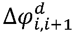
- the azimuthal distance between two pins i, i' is referred to as ⁇ ⁇ i , i d , .
- the azimuthal distance is the distance between two points in azimuthal direction which can be determined easily as the difference of the azimuthal component of their coordinates (assuming cylinder coordinates).
- the n pins each have a forward facing surface, i.e. a surface facing away from the rear-end cap.
- the reference plane is perpendicular to the longitudinal axis and preferably either at the front or at rear side of all n pins.
- the axial position of the reference plane is selected only for conceptual simplicity. Generally, the reference plane could as well be in between of the first and the n th -pin, but then the meaning of the signs indicating the direction of the distances d i and the axial shift ⁇ d i , i +1 alters when transitioning the reference plane).
- This axial shift ⁇ d i has the effect that the filter cartridge can be rotated relative to a tube extending at least partially in the conduit or in which the conduit at least partially extends while being shifted in the forward direction until the first or the n th -pin (depending on the sign of ⁇ d n ) abuts in azimuthal direction against a protrusion on the peripheral surface and/or on the inner surface, respectively of the tube.
- a rotation in the opposite direction is blocked.
- the pins and the protrusions preferably extend at least essentially into opposite directions from opposed surfaces of the conduit and the tube towards their respective counterpart, if the tube is at least partially inserted into the conduit or the conduit is at least partially inserted into the tube.
- the pins may extend at least essentially radially inwards from the inner surface of the conduit wall.
- the conduit may be configured to be received at least partially by the tube and in this another example, the pins may extend at least essentially radially outwards from the peripheral surface of the conduit wall.
- the protrusions extend preferably from the inner side of the tube wall at least essentially towards tube axis. If the tube is configured to be received at least partially by the conduit, the protrusions are preferably on the peripheral surface of the tube and extend at least essentially radially outwards.
- the azimuthal distance ⁇ ⁇ n , 1 d between the n th -pin and the first pin is greater (>) than the maximum azimuthal distance ⁇ i , i + 1 d between any other pair of neighbored pins i, i + 1, 1 ⁇ i ⁇ n.
- the pins may so to speak slide over the read-end cap facing surface of the protrusion, assuming the conduit is attached to or integrated in a front end cap.
- the pins have side surfaces facing in the two opposed azimuthal directions.
- the first pin and the n th -pin each have an azimuthal abutment wherein the two abutments face towards each other.
- These abutments can for example be formed by at least a portion of the opposed side surfaces of two respective pins.
- These abutments enable to center a protrusion with an azimuthal span smaller or equal than the azimuthal distance between the two pins, being explained below in more detail.
- the protrusion may, e.g. be located on a peripheral surface of a tube configured to be inserted into the conduit as explained above.
- ⁇ d i (1 ⁇ ⁇ c ) ⁇ c d , ⁇ 1 ⁇ i ⁇ n, c d being a constant.
- Another aspect of the invention is a tube of a filter socket to which a filter cartridge, e.g. a filter cartridge with at least one of the above described features may be attached to.
- a filter cartridge e.g. a filter cartridge with at least one of the above described features
- these filter sockets are often a part of a filter housing, and they may even be integrated in a filter housing for a filter cartridge, in particular for a filter cartridge as described above.
- the filter housing has a housing bottom and a housing cover.
- the housing cover is preferably removably attached to the bottom.
- the housing cover and the housing bottom enclose a space configure to receive the filter cartridge.
- one may open the filter housing may (if present) remove a previously inserted filter cartridge, insert another or the same filter cartridge and close the housing cover again.
- the removing step is optional, for example, it is necessarily omitted if the filter housing is already empty.
- the filter socket may be located inside the filter housing and may have a tube with a free end.
- the tube has a peripheral surface and a fluid opening configured for receiving fluid from the filter cartridge.
- the fluid flow may be reversed.
- the fluid inlet becomes a fluid outlet, hence the term "fluid inlet” is only a vivid example of the term "fluid opening", the latter term leaving the flow direction open.
- the tube has a tube axis and at least a first protrusion extending from the peripheral surface in an outward direction or from an inner surface at least essentially towards the tube axis.
- the tube can as well be used in other applications and the described integration into a filter housing is only an example for a practical application of the invention.
- the first protrusion may have an azimuthal span ⁇ ⁇ 1 s and a rear end of the corresponding conduit facing surface.
- the azimuthal span ⁇ ⁇ 1 s is greater or equal ( ⁇ ) than the azimuthal distance ⁇ ⁇ i , i + 1 d between the pins of the conduit for all i + 1 ⁇ n and in that the azimuthal span ⁇ ⁇ 1 s is smaller (or equal) than (or to) the azimuthal distance between the n th - and the first pin, i.e., ⁇ ⁇ 1 s ⁇ ⁇ ⁇ n , 1 d .
- the first protrusion fits only in the azimuthal spacing between of the n th -pin and the first pin of the conduit.
- the axial dimension of the protrusion is preferably configured to abut the two mutually opposing azimuthal surfaces of the n th -pin and the first pin.
- the axial dimension l 1 of the first protrusion (as well referred to as the first length l 1 ) is preferably in the order of
- or briefly l 1 (1 ⁇ ⁇ l ) ⁇
- the first length l 1 is greater than
- the first protrusion is counted as well and the azimuthal spans ⁇ ⁇ j s of each of these protrusions as well as their locations ⁇ j are selected to ensure that the cartridge can be advances if (and only if) the space between the n th -pin and the first pin is azimuthally positioned to match the azimuthal position of the first protrusion.
- the ranges ⁇ j over which the protrusions span can be considered as a code which has to be matched by the azimuthal positions and azimuthal spans of the pins.
- the index j indicates the j th protrusion to which the value (range, position span, etc.) is associated.
- first and the second reference planes may be oriented at least essentially parallel to each other (which shall include that both planes become identical in case the filter cartridge reaches its axial end position).
- At least essentially parallel means that parallelism is preferred, but small deviations can be accepted, e.g. deviations smaller than 15°, smaller than 10°, smaller than 5°, smaller than 2.5° or deviations smaller than 1° may be accepted.
- the axial positions of the distally facing surfaces of the protrusions are spaced from each other such that at least two distally facing surfaces each abut at least a front facing surface of a pin, if the condition ⁇ n + ⁇ ⁇ n ⁇ ⁇ 1 ⁇ ⁇ 1 is not met.
- the longitudinal axis of the conduit may be at least essentially aligned to the tube axis, thereby reducing the risk that the pins and the protrusions are jammed, which may result in blocking the filter cartridge from being properly oriented and/or axially advanced towards its intended position.
- the filter housing and the filter cartridge may be combined to form a liquid filter system.
- the corresponding method may comprise at least one of the following steps
- first surface of the conduit and second surface of the tube have only be chosen to be able to verbally distinguish these preferably cylindrical surfaces.
- a cylindrical surface is as usual a surface resembling a cylinder surface.
- a cylindrical surface is at least in part congruent to at least a part of a cylinder surface.
- cylindrical surfaces herein are circular cylindrical surfaces, i.e. at least a portion of the respective circular cylindrical surface is congruent to at least a part of a circular cylinder surface.
- the filter cartridge 1 in Fig. 1 comprises a filter element 50 enclosing a fluid channel 52 having a longitudinal axis 2.
- this longitudinal axis is considered as the filter axis 2.
- the filter element 50 can be for example of plied filter paper as commonly used, e.g. for oil filter cartridges or any other suitable filter material.
- the filter element 50 has e rear end side, which is attached to the forward-facing surface of a rear end cap 60.
- the frontal side of the rear-end cap 60 facing away from the front-end side is hence referred to as rearward facing side 66 of the rear-end cap 60.
- the rear-end cap 60 is represented by a simple disk, but it may as well have through holes, valves, attachment means or the like as known in the art.
- the front-end side of the filter element 60 is attached to a rearward facing side 46 of a front-end cap 40.
- the front-end cap 40 has a through hole 42 enabling filtered fluid to leave the fluid channel 52.
- a conduit 30 being defined by a conduit wall 32 is attached to the front-end cap 40 and encircles the through hole 42. In other words, the inner surface of the conduit 37 defines the through hole 42.
- the conduit 30 Similar to the front-end cap 40, the conduit 30 has a front facing surface 34 and a rearward facing surface 36.
- a number of n pins 20 1 , 20 2 , 20 3 , ... , 20 i , ... , 20 n may protrude from the inner surface 37 of the conduit wall 32 into the free space being enclosed by the conduit wall 32 (see as well Fig. 2 and Fig. 3 ).
- Each pin 20 i (1 ⁇ i ⁇ n) has a forward-facing surface 24 i and at its opposite side a rear-end facing surface 26 i .
- the front end facing surfaces 24 i , 24 i +1 of two neighbored pins 20 i and 20 i +1 ( ⁇ 1 ⁇ i ⁇ n ) are spaced from each other by a distance ⁇ d i (see Fig. 2 ).
- the distances d i of the front facing surfaces 24 i decrease with increasing index i .
- the reference plane may be placed on the other side of the pins 20 i , in this case the distances d i would increase.
- the position of the reference plane is not relevant, but regardless of the choice, the distances should all increase or all decrease when increasing i from 1 to n , assuming the first pin to be either the one closest to the front end or the closest to the rear end of the conduit.
- the pins 20 i are azimuthally spaced as can bee seen in Fig. 2 and Fig. 3 the conduit 30 from the front and aligned with the longitudinal axis 2.
- the first protrusion 20 1 then extends or spans azimuthally by a 'span' ⁇ ⁇ 1 s .
- the next pin 20 2 protrudes out of the inner surface 37 or the conduit wall 32, i.e. at an angle ⁇ 2 .
- ⁇ i extends a pin 20 i having an azimuthal thickness ('span') ⁇ ⁇ i s .
- ⁇ ⁇ n , 1 d is much bigger than all ⁇ ⁇ i , i + 1 d .
- ⁇ ⁇ n , 1 d ⁇ Max ⁇ ⁇ i , i + 1 d : 1 ⁇ i ⁇ n .
- This azimuthal gap ⁇ ⁇ n , 1 d between the n th - pin 20 n and the first pin 20 1 ensures that when inserting the conduit (which may be a part of a filter cartridge 1) it may slide with the front facing surfaces 24 i on any protrusion having an azimuthal span ⁇ ⁇ j s greater than Max ⁇ ⁇ i , i + 1 d : 1 ⁇ i ⁇ n and preferably smaller than the gap ⁇ ⁇ n , 1 d , thereby being guided into a defined azimuthal orientation.
- the protrusion 120 1 see Fig.
- the abutment may be a separate part, only for conceptual simplicity, we attributed the abutment to the first pin, as the abutment delimits a rotation in the direction from ⁇ n to ⁇ i beyond ⁇ i .
- Fig. 4A to Fig. 4E there is the tube 130 having a tube axis 102 being aligned with conduit axis 2.
- the tube 130 has a peripheral surface 138 with a radius smaller or equal to the free radiuses r i of the conduit 30.
- the tube 130 has a rearward facing side 136 and is at least approximately centered in the conduit 30 by the radially inwardly facing surfaces of the pins 20 i .
- the pins 20 i of the conduit are depicted to visualize their interaction with protrusions 120 j extending radially outwardly over the free radius r i of the conduit from the peripheral surface of the tube 130.
- Fig. 4A shows a situation, when a conduit 30 (which may be a part of a filter cartridge 1) with the pins 20 i extending into the through hole 42 is positioned over the tube 130, which may be part of a socket of a filter housing. As shown in Fig. 4A , the conduit 30 may be advanced in the forward direction 3 (see arrow in Fig 4E ) until the at least one front-end side 24 i of a pin 20 i , i.e.
- the pins 20 i slide over the first protrusion 120 1 .
- the forward-facing side of the first pin 20 1 may slides on the rear-end facing side 126 2 of an optional second protrusion 121 2 .
- the conduit 30 may slide on the protrusions 120 j , until a side face of the first pin 20 1 abuts a side face of the first protrusion 120 1 . So to speak, the sides faces mutually limit a further rotation of the conduit as depicted in Fig. 4E .
- the pins 20 i may be moved forward (being indicated by the arrow 3) in to its final position, because the first protrusion 120 1 is aligned with the largest azimuthal gap ⁇ ⁇ n , 1 d , which is (in this example) in between of the n th -pin 20 n and the first pin 20 1 .
- the other protrusions 120 2 to 120 m are preferably smaller than the azimuthal gaps ⁇ ⁇ i , i + 1 d between the corresponding pins 20 i , 20 i +1 .
- the remaining protrusions 120 2 to 120 m are each azimuthally positioned to 'match' with a space between two neighbored pins 20 i .
Landscapes
- Chemical & Material Sciences (AREA)
- Chemical Kinetics & Catalysis (AREA)
- Infusion, Injection, And Reservoir Apparatuses (AREA)
- External Artificial Organs (AREA)
- Filtering Of Dispersed Particles In Gases (AREA)
Description
- The invention relates to components of, e.g., a fluid filter housing and to a fluid filter cartridge, wherein the fluid filter cartridge is preferably configured to be mounted in the fluid filter housing. At least one the fluid filter cartridge and the fluid filter housing has a first cylindrical surface and the respective other of the fluid filter cartridge and the fluid filter housing has a second cylindrical surface. The first and second cylindrical surfaces may be surfaces of a conduit and/or a tube, respectively. The conduit may be the conduit of a fluid filter cartridge and the tube may be the tube of the fluid filter housing. Further, the invention relates to a method for mounting the fluid filter cartridge into the housing.
-
EP 2 956 225 B1 -
WO 02/13944 A2 -
US 2017/0361252 A1 discloses a hollow filter element of a fluid filter. Associated to the filter element is retention/carrier device of a retention/carrier system retaining the filter element in a first housing section of a filter housing during installation and removal in or from a second housing section by rotation and insertion movement, respectively. The filter element-associated retention/carrier device has a retention/carrier part extending radially and circumferentially and has through holes adjacent thereto extending circumferentially so as to enable a filter housing-associated retention/carrier part of the retention/carrier system to pass through axially. - The problem to be solved by the invention is to provide a first article and a second article which are simple and hence cheap to manufacture while at the same time being configured to be mounted to each other in a predefined azimuthal orientation. Another problem to be solved is to provide a filter cartridge and a filter housing, as well being simple to manufacture and being configured to receive the filter cartridge in a predefined azimuthal orientation.
- A solution of the problem is the first article as defined by
claim 1. Advantageous embodiments are subjects of the dependent claims. The first article has a first cylindrical surface and is hence a conduit like structure (conduit, for short). The first cylindrical surface of the conduit like structure may be a peripheral surface of the article, hence the conduit is not necessarily hollow, but it may be. Alternatively, the cylindrical surface may delimit a hollow space of the article, in this case, the conduit is hollow and may preferably have at least an open front end. The other end may be open or closed. In case the first surface delimits a hollow space, there are no restrictions to the shape of the peripheral surface, it can be designed to meet any requirement, be they technical and/or aesthetical. Thus, the term conduit or conduit like structure is a synonym for "a first article having a first cylindrical surface", in this sense the article resembles a straight conduit, and we use the term conduit only for simplicity and because it is more vivid than "a first article having a first cylindrical surface". In this sense "a/the conduit" may be considered as pars pro toto for "a/the first article having a first cylindrical surface", regardless of whether the surface a peripheral surface or faces towards a longitudinal axis of the conduit. - As will be explained in more detail below, the conduit of one of
claims 1 to 5 may be mounted to a tube. The tube and/or the conduit may be integrated into and/or comprised by a filter cartridge of claim 10 or 11 and/or a filter housing ofclaim 12. Like the term conduit can be replaced by "first article", throughout the entire description, the term tube can be replaced herein by "second article with a second cylindrical surface". In this sense, conduit and tube are each a pars pro toto of the respective superordinate terms. None of these is necessarily hollow or necessarily fluid tight or necessarily configured to enable a fluid flow, but as the usage of the terms conduit and tube implies, the conduit and/or tube may be. - The fluid filter cartridge may have a filter element forming a fluid channel with a longitudinal axis. These filter elements are well known and have of a porous material, enabling fluid molecules to pass the filter element, while particles above a given size are held back. These filter elements are widely used and commercially available, while often being made from plied filter paper. A front-end cap and a rear-end cap may be sealingly attached to a front side and to a rear side, respectively of the filter element. Fluid being filtered may thus pass between the front-end cap and the rear-end through the filter element, e.g. radial inward (from the outside into the fluid channel). Filtered fluid may leave the fluid channel via a at least one through hole in the front-end cap and/or the rear end cap.
- In an example, the conduit may have a conduit wall with the first cylindrical surface enclosing a through hole of the conduit. The conduit wall may be attached for example to the front-end cap and may be in fluid communication with the fluid channel via the through hole in the front-end cap. Hence, the conduit may have a front end facing away from the rear-end cap and the rear end of the conduit may face towards the rear-end cap. Filtered oil (being an example fluid herein) may thus flow from the fluid channel through the through hole of the conduit to wherever it is needed.
- The conduit has a number of n pins attached to it, n being an integer, e.g. greater that 4 and/or greater than 5 and/or greater than 6 and/or greater than 8, and/or greater than 10. These n-pins may each extend from an inner surface of the conduit wall towards the conduit axis and/or from the outer peripheral surface of the conduit wall away from the conduit axis. Each of the pins spans an azimuthal angle


- The azimuthal span


- As usual in the field of mechanical engineering, the azimuthal distance is the distance between two points in azimuthal direction which can be determined easily as the difference of the azimuthal component of their coordinates (assuming cylinder coordinates).
- In a preferred example


- Particularly preferred are the azimuthal spans and the azimuthal distances of at least approximately the same size, hence preferably


- The n pins each have a forward facing surface, i.e. a surface facing away from the rear-end cap. Preferably, the distances di in axial direction between the forward facing surfaces and a reference plane either increase or decrease with the respective azimuthal position ϕi of each ith -pin by Δd i-1,i from the (i - 1) th -pin to each ith -pin for all 1 < i ≤ n, thus, d i+1 = di + (1 ± αd ) · Δd i,i+1 , Δd i,i+1 ≠ 0, ∀1 ≤ i < n and αd ∈ A wherein Δdi : = Δd i-1,i ∀1 < i ≤ n and Δd 1: = Δd n,1. An increase of the axial distances di implies that Δd i,i+1 > 0, ∀1 ≤ i < n and correspondingly a decrease Δd i,i+1 < 0, ∀1 ≤ i < n. Thus, the distance di strictly monotonically increases or decrease as a function of the azimuthal position ϕi . Only to allow simple referencing and to explain the concept Δd i,i, is the distance between the front facing surfaces of the ith pin and the i'th pin, where 1 < i ≤ n and 1 < i' ≤ n, i.e. Δdi,i = 0 ∀i. The distance Δd n,1 in axial direction between the front facing surface of the nth -pin to the front facing surface of the first pin is preferably given by

- The reference plane is perpendicular to the longitudinal axis and preferably either at the front or at rear side of all n pins. The axial position of the reference plane is selected only for conceptual simplicity. Generally, the reference plane could as well be in between of the first and the nth -pin, but then the meaning of the signs indicating the direction of the distances di and the axial shift Δd i,i+1 alters when transitioning the reference plane). As already apparent, αdn is an error margin and an element that can be selected from A = {0.25, 0.2, 0.15, 0.1, 0.05, 0.025, 0.01,0 }, i.e. α ∈ A. The symbol " ± " denotes as usual that Δd 1 is in between


- As already apparent from the above, the pins and the protrusions preferably extend at least essentially into opposite directions from opposed surfaces of the conduit and the tube towards their respective counterpart, if the tube is at least partially inserted into the conduit or the conduit is at least partially inserted into the tube. For example, if the conduit is configured to receive the tube, the pins may extend at least essentially radially inwards from the inner surface of the conduit wall. In another example the conduit may be configured to be received at least partially by the tube and in this another example, the pins may extend at least essentially radially outwards from the peripheral surface of the conduit wall. Similarly, if the tube is configured to receive at least a portion of the conduit, the protrusions extend preferably from the inner side of the tube wall at least essentially towards tube axis. If the tube is configured to be received at least partially by the conduit, the protrusions are preferably on the peripheral surface of the tube and extend at least essentially radially outwards.
- In a preferred example, the azimuthal distance


- If at least a portion of the front-end facing surfaces of the pins are inclined in the azimuthal direction this sliding is enhanced. The inclination preferably has as a slope

- As already apparent, the pins have side surfaces facing in the two opposed azimuthal directions. Preferably, the first pin and the nth -pin each have an azimuthal abutment wherein the two abutments face towards each other. These abutments can for example be formed by at least a portion of the opposed side surfaces of two respective pins. These abutments enable to center a protrusion with an azimuthal span smaller or equal than the azimuthal distance between the two pins, being explained below in more detail. The protrusion may, e.g. be located on a peripheral surface of a tube configured to be inserted into the conduit as explained above.
- In a preferred example, the axial distances Δdi between the ith - and the (i + 1) th -pin may be at least essentially constant (within a relative error margin αc, αc ∈ A ) for all pins except of course for the distance between the last (nth -) pin to the first (i = 1) pin. In a more concise manner one may reformulate this as Δdi = (1 ± αc ) · cd , ∀1 ≤ i < n, cd being a constant.
- Another aspect of the invention is a tube of a filter socket to which a filter cartridge, e.g. a filter cartridge with at least one of the above described features may be attached to. In practice these filter sockets are often a part of a filter housing, and they may even be integrated in a filter housing for a filter cartridge, in particular for a filter cartridge as described above.
- The filter housing has a housing bottom and a housing cover. The housing cover is preferably removably attached to the bottom. The housing cover and the housing bottom enclose a space configure to receive the filter cartridge. In practice, one may open the filter housing, may (if present) remove a previously inserted filter cartridge, insert another or the same filter cartridge and close the housing cover again. As indicated, the removing step is optional, for example, it is necessarily omitted if the filter housing is already empty.
- The filter socket may be located inside the filter housing and may have a tube with a free end. The tube has a peripheral surface and a fluid opening configured for receiving fluid from the filter cartridge. Of course, the fluid flow may be reversed. Herein, only for a more vivid presentation we assume the fluid to flow through the filter element into the fluid channel and from there into fluid inlet of the tube. If the fluid flow is reversed, the fluid inlet becomes a fluid outlet, hence the term "fluid inlet" is only a vivid example of the term "fluid opening", the latter term leaving the flow direction open. The tube has a tube axis and at least a first protrusion extending from the peripheral surface in an outward direction or from an inner surface at least essentially towards the tube axis. As already apparent from the above, the tube can as well be used in other applications and the described integration into a filter housing is only an example for a practical application of the invention.
- The first protrusion may have an azimuthal span


- In a particularly preferred example, the first length l 1 is greater than |Δd n,1 | minus the axial length of the first pin or of the nth -pin, depending on which of these is further away from the rear-end, i.e. minus the axial length of those of these two pins being farther to the rear end cap. If lf is the axial length of that pin of these two pins being farther from the rear end, than l 1 obeys preferably l 1 > |Δd n,1 I - lf or preferably at least l 1 ≥ |Δd n,1 I - lf.
- Preferably, tube has a number of m - 1 further protrusions, which protrude from the peripheral surface of the tube and/or from the inner surface of the tube, wherein each of the protrusions has a set of associated azimuthal angles


condition 

- Particularly preferred, the distally facing surfaces of the protrusions, i.e. the surfaces facing towards the rear-end of the conduit (if the tube is mounted) each have a distance δj from the position of the reference plane and a slope of the protrusions st, with


- There may be a second reference plane being orthogonal to the tube axis. Thus, if the conduit and/or the filter cartridge is attached to the tube and/or the socket, the first and the second reference planes may be oriented at least essentially parallel to each other (which shall include that both planes become identical in case the filter cartridge reaches its axial end position). At least essentially parallel means that parallelism is preferred, but small deviations can be accepted, e.g. deviations smaller than 15°, smaller than 10°, smaller than 5°, smaller than 2.5° or deviations smaller than 1° may be accepted.
- Particularly preferred, the axial positions of the distally facing surfaces of the protrusions are spaced from each other such that at least two distally facing surfaces each abut at least a front facing surface of a pin, if the condition ϕn + Δϕn ≤ β 1 ≤ ϕ 1 is not met. Thereby, during adjustment of the azimuthal orientation of the filter cartridge, the longitudinal axis of the conduit may be at least essentially aligned to the tube axis, thereby reducing the risk that the pins and the protrusions are jammed, which may result in blocking the filter cartridge from being properly oriented and/or axially advanced towards its intended position.
- As already apparent, the filter housing and the filter cartridge may be combined to form a liquid filter system. The corresponding method may comprise at least one of the following steps
- inserting the free end of the tube via the through hole into the fluid channel of the filter element;
- pushing the front-end cap towards the socket until at least one of the pins abuts with its forward-facing surface against a distally facing surface of a protrusion;
- while pushing the front-end cap towards the socket, the filter cartridge may be rotated until further rotation is blocked.
- Subsequently one may close the housing cover. Prior to the inserting step one may, if required remove or open the housing cover and remove an already installed filter cartridge, if one is installed.
- Once a further rotation of the cartridge is blocked one may push the cartridge axially until the cartridge abuts an axial block.
- Above, the invention has been described assuming that the pins are on a surface of the conduit and that the protrusions are on a surface of the tube. But the pins could as well be on surface of the tube and the protrusions on a pin facing surface of the conduit. The interaction of the pins and the protrusions would not be altered. The terms first surface of the conduit and second surface of the tube have only be chosen to be able to verbally distinguish these preferably cylindrical surfaces.
- A cylindrical surface is as usual a surface resembling a cylinder surface. Generally, one may say that a cylindrical surface is at least in part congruent to at least a part of a cylinder surface. Further, it is noted that it is preferred but not required that cylindrical surfaces herein are circular cylindrical surfaces, i.e. at least a portion of the respective circular cylindrical surface is congruent to at least a part of a circular cylinder surface. For a commonly accepted definition of a cylinder, please see Handbook of Mathematics Bronshtein, Semendyayev Musiol and Muehlig, 5th ed., Springer Berlin Heidelberg New York, 2007; ISBN 978-3-540-72121-5, therein Chapter 3.3.4 (pages 154ff).
- In the following, the invention will be described by way of example, without limitation of the general inventive concept, on examples of embodiment with reference to the drawings.
-
Fig. 1 shows a sectional view of a filter cartridge with a conduit; -
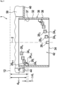
Fig. 2 shows a cross section of a conduit of the cartridge; -
Fig. 3 shows a front view of the conduit ofFig. 2 -
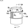
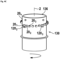
Fig. 4A to 4E show a tube of a filter housing interacting with pins of a cartridge. - The
filter cartridge 1 inFig. 1 comprises afilter element 50 enclosing afluid channel 52 having alongitudinal axis 2. Herein this longitudinal axis is considered as thefilter axis 2. Thefilter element 50 can be for example of plied filter paper as commonly used, e.g. for oil filter cartridges or any other suitable filter material. Thefilter element 50 has e rear end side, which is attached to the forward-facing surface of arear end cap 60. The frontal side of the rear-end cap 60 facing away from the front-end side is hence referred to as rearward facingside 66 of the rear-end cap 60. In this example, the rear-end cap 60 is represented by a simple disk, but it may as well have through holes, valves, attachment means or the like as known in the art. The front-end side of thefilter element 60 is attached to a rearward facingside 46 of a front-end cap 40. The front-end cap 40 has a throughhole 42 enabling filtered fluid to leave thefluid channel 52. Aconduit 30 being defined by aconduit wall 32 is attached to the front-end cap 40 and encircles the throughhole 42. In other words, the inner surface of theconduit 37 defines the throughhole 42. Similar to the front-end cap 40, theconduit 30 has afront facing surface 34 and a rearward facing surface 36. - At this point it is noted that in this example the
tube axis 2 and thefilter axis 2 coincide, but this not necessarily the case as explained in detail inEP 3 249 184 - A number of n pins 201, 202, 203, ... , 20 i , ... , 20 n may protrude from the
inner surface 37 of theconduit wall 32 into the free space being enclosed by the conduit wall 32 (see as wellFig. 2 andFig. 3 ). Each pin 20 i (1 ≤ i ≤ n) has a forward-facingsurface 24 i and at its opposite side a rear-end facing surface 26 i . As shown, the frontend facing surfaces pins 20 i and 20 i+1 (∀1 ≤ i < n) are spaced from each other by a distance Δdi (seeFig. 2 ). Thus, relative to areference plane 12, the distances di of the front facing surfaces 24 i decrease with increasing index i. Generally, the reference plane may be placed on the other side of thepins 20 i , in this case the distances di would increase. The position of the reference plane is not relevant, but regardless of the choice, the distances should all increase or all decrease when increasing i from 1 to n, assuming the first pin to be either the one closest to the front end or the closest to the rear end of the conduit. - In addition, the
pins 20 i are azimuthally spaced as can bee seen inFig. 2 andFig. 3 theconduit 30 from the front and aligned with thelongitudinal axis 2. ϕ 1 is the angle at which the first protrusion (i = 1) starts. Thefirst protrusion 201 then extends or spans azimuthally by a 'span'
distance 
next pin 202 protrudes out of theinner surface 37 or theconduit wall 32, i.e. at an angle ϕ 2. Generalizing, at each azimuthal position ϕi extends apin 20 i having an azimuthal thickness ('span')
pin 20 i is followed by a pin20 i+1(, but of course the direction could be inverted) and the azimuthal spacing (the azimuthal gap) between the ith -pin 20 i and its subsequent (i + 1) st -pin 20 i+1 is the gap

Fig. 3 ,


pin 20 n and thefirst pin 201 ensures that when inserting the conduit (which may be a part of a filter cartridge 1) it may slide with the front facing surfaces 24 i on any protrusion having an azimuthal span


Fig. 4A ) has an axial span

pin 20 n and thefirst pin 201 and/or has an azimuthal abutment closing the axial gap between thefirst pin 201 and the nth -pin 20 n . The abutment may be a separate part, only for conceptual simplicity, we attributed the abutment to the first pin, as the abutment delimits a rotation in the direction from ϕn to ϕi beyond ϕi . - This mechanism of azimuthally orienting the
conduit 30 and hence any part comprising the conduit (e.g., thefilter cartridge 1 ofFig. 1 ) relative to thetube 130 another part is visualized inFig. 4A to Fig. 4E : InFig. 4A to 4E there is thetube 130 having a tube axis 102 being aligned withconduit axis 2. Thetube 130 has aperipheral surface 138 with a radius smaller or equal to the free radiuses ri of theconduit 30. Thus, when inserting thetube 130 into theconduit 30, thetube 130 has a rearward facingside 136 and is at least approximately centered in theconduit 30 by the radially inwardly facing surfaces of thepins 20 i . InFig. 4A to 4E only thepins 20 i of the conduit are depicted to visualize their interaction with protrusions 120 j extending radially outwardly over the free radius ri of the conduit from the peripheral surface of thetube 130. -
Fig. 4A shows a situation, when a conduit 30 (which may be a part of a filter cartridge 1) with thepins 20 i extending into the throughhole 42 is positioned over thetube 130, which may be part of a socket of a filter housing. As shown inFig. 4A , theconduit 30 may be advanced in the forward direction 3 (see arrow inFig 4E ) until the at least one front-end side 24 i of apin 20 i , i.e. the forward facingsurface 24 i of apin 20 i , abuts the rear end facing side 126 j of an jth -protrusion 120 j having an azimuthal span

conduit 30 in the forward direction is blocked by the rear end facing side 1261 of the first protrusion 1201 abutting the forward-facingsurface 241 of thefirst pin 201. While applying a slight force in theforward direction 3, one may rotate thefilter conduit 30 relative to thetube 130 in the direction being indicated by a bent arrow. As can be seen inFig. 4B , thepins 20 i slide over the first protrusion 1201. After a given rotation, the forward-facing side of thefirst pin 201 may slides on the rear-end facing side 1262 of an optional second protrusion 1212. In this preferred example, the second protrusion 1212 optionally has an axial offset corresponding to the slope
pins 20 i , Further, if optional protrusions 120 j are positioned accordingly (, as shown inFig. 4C as protrusions 1202,1203), the front facingsides 24 i of thepins 20 i , may slide on or over the rear-end facing surfaces 126 j of the protrusions 120 j . - The
conduit 30 may slide on the protrusions 120 j , until a side face of thefirst pin 201 abuts a side face of the first protrusion 1201. So to speak, the sides faces mutually limit a further rotation of the conduit as depicted inFig. 4E . - Next, as can be seen in
Fig. 4D , thepins 20 i may be moved forward (being indicated by the arrow 3) in to its final position, because the first protrusion 1201 is aligned with the largest azimuthal gap
pin 20 n and thefirst pin 201. The other protrusions 1202 to 120m are preferably smaller than the azimuthal gaps
first pin 201 and the first protrusion 1201 abut, the axial projections of the rear-end facing surfaces 126 j in the rearward direction (being opposite to thearrow 3 inFig. 4E indicatin the forward) do not interfere with the position of apin 20 i . Further, forward projections of the front facing surfaces 24 i do not interfere with the protrusions 120 j . -
- 1 filter cartridge
- 2 longitudinal axis
- 12 reference plane
- 20 i pins (1 ≤ i ≤ n )
- 24 i forward facing surface of the ith -pin / surface of the ith -pin facing away from the rear-end cap
- 25 i radially inwardly facing surface of the ith -pin
- 26 i rear-end cap facing surface of the ith -pin
- 29 i abutment
- 30 conduit
- 32 conduit wall
- 34 front end
- 36 rear end
- 37 inner surface of conduit
- 38 outer surface of conduit
- 40 front-end cap
- 42 through hole
- 50 filter element
- 52 channel of filter element
- 60 rear-end cap
- 64 front-end cap facing surface of the rear-
end cap 60 - 66 rearward facing surface of the rear-
end cap 60, wherein therear facing surface 66 faces in the opposite direction as the front-endcap facing surface 64 of the rear-end cap 60 - 100 filter housing
- 102 longitudinal axis
- 120 j protusions (1 ≤ i ≤ m )
- 124 j forward facing surface of the jth -protrusion
- 125 j radially outwardly facing surface of the jth -protrusion
- 126 j rear-end cap facing surface of the jth -protrusion
- 129 j abutment
- 130 tube
- 136 rear-end cap facing side of
tube 130/ distal end oftube 130 / free end oftube 130 - 138 peripheral surface of
tube 130 - di distance between the ith -end cap facing surfaces 22 i of the ith -pin and
reference plane 12 - Δd i,i' axial distance between the front facing surfaces 24 i , 24 i' of the ith and the i'th-
pin - ϕi azimuthal position of the ith -pin
-

-

pin 20 i and the i'th -pin 20 i , -

-

- ri free radius as defined by the radially inwardly facing surface of the ith -pin
- Rj max radius as defined by the radially outwardly facing surface of the jth -protrusion
Claims (14)
- A conduit (30) for a fluid filter cartridge and/or a filter cartridge housing, wherein the conduit (30) has a first cylindrical surface (37, 38) defining a first longitudinal axis (2), wherein- the first cylindrical surface (37, 38) has a front end and a rear end,- a natural number of n pins (20 i , 1 ≤ i ≤ n) extends from the first cylindrical surface (37, 38) at azimuthal positions ϕi , to

 - each pin (20 i ) has a forward-facing surface (24 i ), facing away from the rear-end,- the ith -pin (20 i ) and the (i + 1) th -pin (20i+1) are spaced from each other in the azimuthal direction by a distancecharacterized in that
distances (di ) between the forward facing surfaces (24 i ) and a reference plane (12) increase or decrease with the respective azimuthal positions (ϕi ) of the ith -pin (20 i ) by a change in distance Δd i,i+1 from the first pin (201) towards the nth -pin (20 n ) and by a value of


- The conduit (30) for a fluid filter cartridge and/or a filter cartridge housing, respectively of claim 1, characterized in that the conduit (30) comprises at least a conduit wall (32) with a front end (34), a rear end (36), an inner surface (37) and an outer surface (38), characterized in that the inner surface (37) or the outer surface (38) is the first cylindrical surface (37, 38) of the conduit (30).
- The conduit (30) for a fluid filter cartridge and/or a filter cartridge housing, respectively, of claim 1 or 2, characterized in, that
at least a portion of the front end (34) facing surfaces (24 i ) of the pins (20 i ) are inclined in the azimuthal direction. - The conduit (30) for a fluid filter cartridge and/or a filter cartridge housing, respectively, of at least one of claims 1 to 3, characterized in, that the first pin (201) and the nth -pin (20 n ) each have mutually opposed azimuthal abutments.
- The conduit (30) for a fluid filter cartridge and/or a filter cartridge housing, respectively, of at least one of claims 1 to 4, characterized in that the changes of distance Δdi obey Δdi = ci , ∀1 ≤ i < n and/or Δdi = ci ·

- A kit comprising- the conduit (30) for a fluid filter cartridge and/or a filter cartridge housing, respectively, of at least one of claims 1 to 5 and- a tube (130) for a filter cartridge housing and/or a fluid filter cartridge with a second cylindrical surface (138) for being received at least partially by a first volume enclosed by the first cylindrical surface (37, 38) of the conduit (30) or for receiving at least partially the first cylindrical surface (37, 38) in a second volume being enclosed by the second cylindrical surface (138), wherein- the second cylindrical surface defines a second longitudinal axis (102) and has a second front end and a second rear end, and- at least a first protrusion (1201) extends from the second cylindrical surface (138), and- the first protrusion (1201) has an azimuthal spancharacterized in that

the azimuthal span


- The kit of claim 6, characterized in that a number of m - 1 further protrusions (120 j , 2 ≤ j ≤ m) protrude from the second surface (138) wherein each of the protrusions (120j) has a set of associated azimuthal angles


- The kit of one of claims 6 or 7, wherein the tube (130) comprises at least a tube wall with a front end, a rear end, an inner surface and an outer surface, characterized in that the inner surface or the outer surface is the second cylindrical surface (138) of the tube (130).
- A fluid filter cartridge (1), comprising at least:- a filter element (50) forming a fluid channel (52) with a longitudinal channel axis (2) and having a front side and a rear side- a through hole (42) in the front-side- the conduit (30) of one of claims 1 to 5, wherein the conduit (30) is in fluid communication with the fluid channel (52) via the through hole (42) in the front-side of the fluid filter cartridge (1), and wherein the front-end (34) of the conduit (30) faced away from the rear-end of the fluid filter cartridge (1) and wherein the longitudinal channel axis (2) is the first longitudinal axis (2).
- The filter cartridge (1) of claim 9, characterized in that it further comprises:- a front-end cap (40) being sealingly attached to the front side of the filter element (50),- a rear-end cap (60) being sealingly attached to the rear side of the filter element (50).
- A filter system comprising- the filter cartridge (1) of one of claims 9 or 10,- a filter housing (100) for the filter cartridge (1) of claim 9 or 10, wherein the filter housing (100) comprises at least:- a housing bottom,- a housing cover being removably attached to the bottom, wherein the housing cover and the housing bottom enclose a space configured to receive the filter cartridge,- a filter socket wherein the filter socket is located inside the filter housing,characterized in that
the filter socket has the tube (130) of the kit of one of claims 6 to 8, at least the front end or the rear end of the tube (130) is a free end (136), the tube (130) has a fluid opening for receiving and/or providing fluid from and/or to the filter cartridge (1), respectively. - A method for mounting the filter cartridge (1) of one of claims 9 or 10 into the filter housing (100) of the filter system of claim 11, characterized in that the method comprises at least the steps of:12.1. inserting the free end (136) of the conduit (30) via the through hole (42) of the filter element into the fluid channel (52) of the filter element (50);12.2. pushing the front-end of the conduit (30) towards the socket until at least one of the pins (20 i ) abuts with its forward-facing surface (24 i ) against a surface (126 j ) of a protrusion (120 j );12.3. while pushing the front-end towards the socket, rotating the filter cartridge (1) until further rotation is blocked.
- The method of claim 12, characterized in that it further comprises closing the housing cover.
- The method of claim 13, characterized in that it further comprises, between steps 12.3 and the step of claim 13:
14.1. pushing the front end cap (40) towards the socket until the filter cartridge abuts an axial block.
Priority Applications (6)
| Application Number | Priority Date | Filing Date | Title |
|---|---|---|---|
| EP22184720.5A EP4306194B1 (en) | 2022-07-13 | 2022-07-13 | A conduit for a fluid filter cartridge, a kit and a fluid filter cartridge comprising said conduit and a method for mounting the filter cartridge |
| PL22184720.5T PL4306194T3 (en) | 2022-07-13 | 2022-07-13 | A conduit for a fluid filter cartridge, a kit and a fluid filter cartridge comprising said conduit and a method for mounting the filter cartridge |
| ES22184720T ES3014453T3 (en) | 2022-07-13 | 2022-07-13 | A conduit for a fluid filter cartridge, a kit and a fluid filter cartridge comprising said conduit and a method for mounting the filter cartridge |
| CN202380065370.0A CN119855640A (en) | 2022-07-13 | 2023-07-13 | Fluid filter and housing for a fluid filter |
| PCT/EP2023/069495 WO2024013305A1 (en) | 2022-07-13 | 2023-07-13 | Fluid filter and housing for the fluid filter |
| US19/016,465 US12478901B2 (en) | 2022-07-13 | 2025-01-10 | Fluid filter and housing for the fluid filter |
Applications Claiming Priority (1)
| Application Number | Priority Date | Filing Date | Title |
|---|---|---|---|
| EP22184720.5A EP4306194B1 (en) | 2022-07-13 | 2022-07-13 | A conduit for a fluid filter cartridge, a kit and a fluid filter cartridge comprising said conduit and a method for mounting the filter cartridge |
Publications (3)
| Publication Number | Publication Date |
|---|---|
| EP4306194A1 EP4306194A1 (en) | 2024-01-17 |
| EP4306194B1 true EP4306194B1 (en) | 2025-01-22 |
| EP4306194C0 EP4306194C0 (en) | 2025-01-22 |
Family
ID=82594906
Family Applications (1)
| Application Number | Title | Priority Date | Filing Date |
|---|---|---|---|
| EP22184720.5A Active EP4306194B1 (en) | 2022-07-13 | 2022-07-13 | A conduit for a fluid filter cartridge, a kit and a fluid filter cartridge comprising said conduit and a method for mounting the filter cartridge |
Country Status (6)
| Country | Link |
|---|---|
| US (1) | US12478901B2 (en) |
| EP (1) | EP4306194B1 (en) |
| CN (1) | CN119855640A (en) |
| ES (1) | ES3014453T3 (en) |
| PL (1) | PL4306194T3 (en) |
| WO (1) | WO2024013305A1 (en) |
Families Citing this family (1)
| Publication number | Priority date | Publication date | Assignee | Title |
|---|---|---|---|---|
| EP4691591A1 (en) | 2024-08-06 | 2026-02-11 | Hengst SE | Fluid filter insert and fluid filter housing |
Family Cites Families (6)
| Publication number | Priority date | Publication date | Assignee | Title |
|---|---|---|---|---|
| US6146527A (en) * | 1998-04-21 | 2000-11-14 | Parker-Hannifin Corporation | Spin-on filter cartridge with replaceable element |
| ATE516066T1 (en) * | 2000-08-11 | 2011-07-15 | Omnipure Filter Company Inc | PROFILE SYSTEM FOR CONNECTING FILTER CARTRIDGE AND FILTER HOLDER |
| DE102013202449A1 (en) | 2013-02-14 | 2014-08-14 | Mahle International Gmbh | filter device |
| DE102014213105A1 (en) | 2014-07-07 | 2016-01-07 | Volkswagen Ag | Fuel cell unit with exchangeable Entionisierungseinrichtung and vehicle with such |
| EP3249184B1 (en) | 2016-05-23 | 2018-07-18 | Hengst SE | Oil filter cartridge and housing for an oil filter cartridge |
| DE102017005619A1 (en) * | 2016-06-16 | 2017-12-21 | Mann + Hummel Gmbh | Hollow filter element, filter and housing part of a filter |
-
2022
- 2022-07-13 EP EP22184720.5A patent/EP4306194B1/en active Active
- 2022-07-13 ES ES22184720T patent/ES3014453T3/en active Active
- 2022-07-13 PL PL22184720.5T patent/PL4306194T3/en unknown
-
2023
- 2023-07-13 WO PCT/EP2023/069495 patent/WO2024013305A1/en not_active Ceased
- 2023-07-13 CN CN202380065370.0A patent/CN119855640A/en active Pending
-
2025
- 2025-01-10 US US19/016,465 patent/US12478901B2/en active Active
Also Published As
| Publication number | Publication date |
|---|---|
| PL4306194T3 (en) | 2025-07-28 |
| CN119855640A (en) | 2025-04-18 |
| EP4306194A1 (en) | 2024-01-17 |
| US20250205620A1 (en) | 2025-06-26 |
| ES3014453T3 (en) | 2025-04-22 |
| US12478901B2 (en) | 2025-11-25 |
| WO2024013305A1 (en) | 2024-01-18 |
| EP4306194C0 (en) | 2025-01-22 |
Similar Documents
| Publication | Publication Date | Title |
|---|---|---|
| US12478901B2 (en) | Fluid filter and housing for the fluid filter | |
| EP3644105B1 (en) | Fiber optic connection system with fast coupling mechanism | |
| US4154510A (en) | Lens barrel | |
| US12215813B2 (en) | Plumbing fitting | |
| ES2483716T3 (en) | Radial seal set | |
| TW202144201A (en) | Valve | |
| CN103782456A (en) | Plug connectors for protective contacts | |
| TWI598707B (en) | Toner cartridge | |
| EP3249184B1 (en) | Oil filter cartridge and housing for an oil filter cartridge | |
| BR112016023457B1 (en) | FILTER ELEMENT AND ASSEMBLY | |
| US6369960B2 (en) | Securing device for light interception frame | |
| CN114402157A (en) | Quick Connectors and Connecting Assemblies with Improved Seal Ring Locking | |
| CN107654651A (en) | The manufacture method of seal assembly and the seal assembly | |
| AU733449B2 (en) | A rotating seal ring component kit for a mechanical split seal | |
| CN111742171A (en) | Connector for loop element | |
| CN113911202A (en) | Ball circulation assembly and steering gear | |
| US20040136777A1 (en) | Bayonet coupling for axially mounting one of two relatively rotatable ring-shaped members on the other | |
| CN115997082A (en) | fluid connection components | |
| CN107709814B (en) | tolerance ring | |
| EP3862600B1 (en) | Sliding member | |
| US12210268B2 (en) | Lens barrel and camera equipped with same | |
| CN206411426U (en) | Individual toner cartridges | |
| ES3018913T3 (en) | Plumbing fitting | |
| GB2395992A (en) | Tube coupling with tube release apparatus | |
| CN211847192U (en) | Filter element assembly and water purifying equipment |
Legal Events
| Date | Code | Title | Description |
|---|---|---|---|
| PUAI | Public reference made under article 153(3) epc to a published international application that has entered the european phase |
Free format text: ORIGINAL CODE: 0009012 |
|
| STAA | Information on the status of an ep patent application or granted ep patent |
Free format text: STATUS: THE APPLICATION HAS BEEN PUBLISHED |
|
| STAA | Information on the status of an ep patent application or granted ep patent |
Free format text: STATUS: REQUEST FOR EXAMINATION WAS MADE |
|
| AK | Designated contracting states |
Kind code of ref document: A1 Designated state(s): AL AT BE BG CH CY CZ DE DK EE ES FI FR GB GR HR HU IE IS IT LI LT LU LV MC MK MT NL NO PL PT RO RS SE SI SK SM TR |
|
| 17P | Request for examination filed |
Effective date: 20231228 |
|
| RBV | Designated contracting states (corrected) |
Designated state(s): AL AT BE BG CH CY CZ DE DK EE ES FI FR GB GR HR HU IE IS IT LI LT LU LV MC MK MT NL NO PL PT RO RS SE SI SK SM TR |
|
| STAA | Information on the status of an ep patent application or granted ep patent |
Free format text: STATUS: EXAMINATION IS IN PROGRESS |
|
| 17Q | First examination report despatched |
Effective date: 20240402 |
|
| GRAP | Despatch of communication of intention to grant a patent |
Free format text: ORIGINAL CODE: EPIDOSNIGR1 |
|
| STAA | Information on the status of an ep patent application or granted ep patent |
Free format text: STATUS: GRANT OF PATENT IS INTENDED |
|
| INTG | Intention to grant announced |
Effective date: 20240619 |
|
| GRAS | Grant fee paid |
Free format text: ORIGINAL CODE: EPIDOSNIGR3 |
|
| GRAJ | Information related to disapproval of communication of intention to grant by the applicant or resumption of examination proceedings by the epo deleted |
Free format text: ORIGINAL CODE: EPIDOSDIGR1 |
|
| GRAL | Information related to payment of fee for publishing/printing deleted |
Free format text: ORIGINAL CODE: EPIDOSDIGR3 |
|
| STAA | Information on the status of an ep patent application or granted ep patent |
Free format text: STATUS: EXAMINATION IS IN PROGRESS |
|
| GRAP | Despatch of communication of intention to grant a patent |
Free format text: ORIGINAL CODE: EPIDOSNIGR1 |
|
| STAA | Information on the status of an ep patent application or granted ep patent |
Free format text: STATUS: GRANT OF PATENT IS INTENDED |
|
| INTC | Intention to grant announced (deleted) | ||
| INTG | Intention to grant announced |
Effective date: 20241009 |
|
| GRAA | (expected) grant |
Free format text: ORIGINAL CODE: 0009210 |
|
| STAA | Information on the status of an ep patent application or granted ep patent |
Free format text: STATUS: THE PATENT HAS BEEN GRANTED |
|
| AK | Designated contracting states |
Kind code of ref document: B1 Designated state(s): AL AT BE BG CH CY CZ DE DK EE ES FI FR GB GR HR HU IE IS IT LI LT LU LV MC MK MT NL NO PL PT RO RS SE SI SK SM TR |
|
| REG | Reference to a national code |
Ref country code: GB Ref legal event code: FG4D |
|
| REG | Reference to a national code |
Ref country code: CH Ref legal event code: EP |
|
| REG | Reference to a national code |
Ref country code: IE Ref legal event code: FG4D |
|
| REG | Reference to a national code |
Ref country code: DE Ref legal event code: R096 Ref document number: 602022009743 Country of ref document: DE |
|
| U01 | Request for unitary effect filed |
Effective date: 20250218 |
|
| U07 | Unitary effect registered |
Designated state(s): AT BE BG DE DK EE FI FR IT LT LU LV MT NL PT RO SE SI Effective date: 20250224 |
|
| REG | Reference to a national code |
Ref country code: ES Ref legal event code: FG2A Ref document number: 3014453 Country of ref document: ES Kind code of ref document: T3 Effective date: 20250422 |
|
| PG25 | Lapsed in a contracting state [announced via postgrant information from national office to epo] |
Ref country code: RS Free format text: LAPSE BECAUSE OF FAILURE TO SUBMIT A TRANSLATION OF THE DESCRIPTION OR TO PAY THE FEE WITHIN THE PRESCRIBED TIME-LIMIT Effective date: 20250422 |
|
| PG25 | Lapsed in a contracting state [announced via postgrant information from national office to epo] |
Ref country code: IS Free format text: LAPSE BECAUSE OF FAILURE TO SUBMIT A TRANSLATION OF THE DESCRIPTION OR TO PAY THE FEE WITHIN THE PRESCRIBED TIME-LIMIT Effective date: 20250522 Ref country code: NO Free format text: LAPSE BECAUSE OF FAILURE TO SUBMIT A TRANSLATION OF THE DESCRIPTION OR TO PAY THE FEE WITHIN THE PRESCRIBED TIME-LIMIT Effective date: 20250422 |
|
| PG25 | Lapsed in a contracting state [announced via postgrant information from national office to epo] |
Ref country code: HR Free format text: LAPSE BECAUSE OF FAILURE TO SUBMIT A TRANSLATION OF THE DESCRIPTION OR TO PAY THE FEE WITHIN THE PRESCRIBED TIME-LIMIT Effective date: 20250122 |
|
| PG25 | Lapsed in a contracting state [announced via postgrant information from national office to epo] |
Ref country code: GR Free format text: LAPSE BECAUSE OF FAILURE TO SUBMIT A TRANSLATION OF THE DESCRIPTION OR TO PAY THE FEE WITHIN THE PRESCRIBED TIME-LIMIT Effective date: 20250423 |
|
| U20 | Renewal fee for the european patent with unitary effect paid |
Year of fee payment: 4 Effective date: 20250729 |
|
| PG25 | Lapsed in a contracting state [announced via postgrant information from national office to epo] |
Ref country code: SM Free format text: LAPSE BECAUSE OF FAILURE TO SUBMIT A TRANSLATION OF THE DESCRIPTION OR TO PAY THE FEE WITHIN THE PRESCRIBED TIME-LIMIT Effective date: 20250122 |
|
| PGFP | Annual fee paid to national office [announced via postgrant information from national office to epo] |
Ref country code: ES Payment date: 20250819 Year of fee payment: 4 |
|
| PGFP | Annual fee paid to national office [announced via postgrant information from national office to epo] |
Ref country code: TR Payment date: 20250707 Year of fee payment: 4 Ref country code: PL Payment date: 20250627 Year of fee payment: 4 |
|
| PG25 | Lapsed in a contracting state [announced via postgrant information from national office to epo] |
Ref country code: CZ Free format text: LAPSE BECAUSE OF FAILURE TO SUBMIT A TRANSLATION OF THE DESCRIPTION OR TO PAY THE FEE WITHIN THE PRESCRIBED TIME-LIMIT Effective date: 20250122 |
|
| PG25 | Lapsed in a contracting state [announced via postgrant information from national office to epo] |
Ref country code: SK Free format text: LAPSE BECAUSE OF FAILURE TO SUBMIT A TRANSLATION OF THE DESCRIPTION OR TO PAY THE FEE WITHIN THE PRESCRIBED TIME-LIMIT Effective date: 20250122 |
|
| PLBE | No opposition filed within time limit |
Free format text: ORIGINAL CODE: 0009261 |
|
| STAA | Information on the status of an ep patent application or granted ep patent |
Free format text: STATUS: NO OPPOSITION FILED WITHIN TIME LIMIT |
|
| REG | Reference to a national code |
Ref country code: CH Ref legal event code: L10 Free format text: ST27 STATUS EVENT CODE: U-0-0-L10-L00 (AS PROVIDED BY THE NATIONAL OFFICE) Effective date: 20251203 |
|
| 26N | No opposition filed |
Effective date: 20251023 |
|
| REG | Reference to a national code |
Ref country code: CH Ref legal event code: H13 Free format text: ST27 STATUS EVENT CODE: U-0-0-H10-H13 (AS PROVIDED BY THE NATIONAL OFFICE) Effective date: 20260224 |
|
| PG25 | Lapsed in a contracting state [announced via postgrant information from national office to epo] |
Ref country code: CH Free format text: LAPSE BECAUSE OF NON-PAYMENT OF DUE FEES Effective date: 20250731 |
|
| PG25 | Lapsed in a contracting state [announced via postgrant information from national office to epo] |
Ref country code: IE Free format text: LAPSE BECAUSE OF NON-PAYMENT OF DUE FEES Effective date: 20250713 |
|
| PG25 | Lapsed in a contracting state [announced via postgrant information from national office to epo] |
Ref country code: MC Free format text: LAPSE BECAUSE OF FAILURE TO SUBMIT A TRANSLATION OF THE DESCRIPTION OR TO PAY THE FEE WITHIN THE PRESCRIBED TIME-LIMIT Effective date: 20250122 |
|
| PG25 | Lapsed in a contracting state [announced via postgrant information from national office to epo] |
Ref country code: CY Free format text: LAPSE BECAUSE OF FAILURE TO SUBMIT A TRANSLATION OF THE DESCRIPTION OR TO PAY THE FEE WITHIN THE PRESCRIBED TIME-LIMIT Effective date: 20250122 |