EP4304268A1 - Time slot allocation processing method, and device and storage medium - Google Patents
Time slot allocation processing method, and device and storage medium Download PDFInfo
- Publication number
- EP4304268A1 EP4304268A1 EP22762591.0A EP22762591A EP4304268A1 EP 4304268 A1 EP4304268 A1 EP 4304268A1 EP 22762591 A EP22762591 A EP 22762591A EP 4304268 A1 EP4304268 A1 EP 4304268A1
- Authority
- EP
- European Patent Office
- Prior art keywords
- node device
- slot
- delay
- node
- determined
- Prior art date
- Legal status (The legal status is an assumption and is not a legal conclusion. Google has not performed a legal analysis and makes no representation as to the accuracy of the status listed.)
- Pending
Links
Images


Classifications
-
- H—ELECTRICITY
- H04—ELECTRIC COMMUNICATION TECHNIQUE
- H04J—MULTIPLEX COMMUNICATION
- H04J3/00—Time-division multiplex systems
- H04J3/16—Time-division multiplex systems in which the time allocation to individual channels within a transmission cycle is variable, e.g. to accommodate varying complexity of signals, to vary number of channels transmitted
- H04J3/1605—Fixed allocated frame structures
- H04J3/1652—Optical Transport Network [OTN]
- H04J3/1658—Optical Transport Network [OTN] carrying packets or ATM cells
-
- H—ELECTRICITY
- H04—ELECTRIC COMMUNICATION TECHNIQUE
- H04W—WIRELESS COMMUNICATION NETWORKS
- H04W72/00—Local resource management
- H04W72/04—Wireless resource allocation
- H04W72/044—Wireless resource allocation based on the type of the allocated resource
- H04W72/0446—Resources in time domain, e.g. slots or frames
-
- H—ELECTRICITY
- H04—ELECTRIC COMMUNICATION TECHNIQUE
- H04L—TRANSMISSION OF DIGITAL INFORMATION, e.g. TELEGRAPHIC COMMUNICATION
- H04L43/00—Arrangements for monitoring or testing data switching networks
- H04L43/08—Monitoring or testing based on specific metrics, e.g. QoS, energy consumption or environmental parameters
- H04L43/0852—Delays
-
- H—ELECTRICITY
- H04—ELECTRIC COMMUNICATION TECHNIQUE
- H04J—MULTIPLEX COMMUNICATION
- H04J2203/00—Aspects of optical multiplex systems other than those covered by H04J14/05 and H04J14/07
- H04J2203/0001—Provisions for broadband connections in integrated services digital network using frames of the Optical Transport Network [OTN] or using synchronous transfer mode [STM], e.g. SONET, SDH
- H04J2203/0073—Services, e.g. multimedia, GOS, QOS
- H04J2203/0082—Interaction of SDH with non-ATM protocols
- H04J2203/0085—Support of Ethernet
-
- H—ELECTRICITY
- H04—ELECTRIC COMMUNICATION TECHNIQUE
- H04J—MULTIPLEX COMMUNICATION
- H04J2203/00—Aspects of optical multiplex systems other than those covered by H04J14/05 and H04J14/07
- H04J2203/0001—Provisions for broadband connections in integrated services digital network using frames of the Optical Transport Network [OTN] or using synchronous transfer mode [STM], e.g. SONET, SDH
- H04J2203/0089—Multiplexing, e.g. coding, scrambling, SONET
- H04J2203/0091—Time slot assignment
Definitions
- the disclosure relates to the technical field of communications, and in particular to a method for processing slot allocation, a device and a storage medium.
- Ethernet FlexE
- OIF Optical Internet Forum
- MTN Metro transport network
- ITU-T ITU-Telecommunication standardization sector
- MTN is composed of a section layer and a path layer.
- a MTN section layer supports slot division and port binding, and is compatible with Ethernet underlying protocol stack and standard Ethernet optical module.
- a path layer of metro transmission network supports TDM switching based on 66B code blocks, has a comprehensive end-to-end operation administration and maintenance (OAM) mechanism, and supports cross-multiplexing of channelized customer signals with any Nx5G or smaller bandwidth particles.
- OAM end-to-end operation administration and maintenance
- the deficiency of the related art is that the current method for establishing an end-to-end slicing channel will increase a processing delay within a node due to the method for slot allocation.
- the disclosure provides a method for processing slot allocation, a device and a storage medium to solve the problem of an increasing processing delay within a node due to the method for slot allocation.
- the disclosure provides the following technical solutions.
- a method for processing slot allocation including the following operations.
- a node device determines a delay within the node device from a certain slot at an input port to another slot at an port, where the node device is a node device on an end-to-end channel.
- the node device determines that the delay is used for establishing slot allocation on the end-to-end channel.
- the operation that the node device determines the delay for establishing the slot allocation on the end-to-end channel may include the following operations.
- the node device transmits the delay to a centralized system; and/or the node device determines an available slot for the node device according to a slot with an optimal delay, and then transmits the available slot for the node device to a next node device on the channel.
- the delay determined by the node device may be determined by the node device by itself; and/or the delay determined by the node device may be determined upon reception of a request for determining the delay.
- the request for determining the delay may be transmitted by a centralized system to node devices on a node device path after determining the node device path that the end-to-end channel passes through.
- the delay within the node device from the certain slot at the input port to the another slot at the port determined by the node device may be a delay value between other slots determined by the node device after the node device determines a delay within the node device from a certain slot A at an input port p to another slot B at an output port q.
- the delay value between other slots may be determined based on a frame structure with slots and a pre-acquired node delay variation model.
- the method may further include the following operations.
- An available slot determined by a previous node device on the channel according to a slot with an optimal delay for the previous node device is received.
- An available slot for the node device is determined according to a slot with an optimal delay for the node device, and then the available slot for the node device is transmitted to the next node device on the channel.
- a method for processing slot allocation includes the following operations.
- An available slot determined by a previous node device on a channel according to a slot with an optimal delay for the previous node device is received.
- An available slot for a current node device is determined according to a slot with an optimal delay for the current node device, and then the available slot for the current node device is transmitted to a next node device on the channel.
- determining delays of available slots comprises: for each of node devices, determining, by the node device, the delay within the node device from a certain slot at an input port to another slot at an port, wherein each of the node devices is a node device on an end-to-end channel, and the delays are used for establishing slot allocation on the end-to-end channel.
- the delay determined by the node device may be determined by the node device by itself; and/or the delay determined by the node device may be determined upon reception of a request for determining the delay.
- the request for determining the delay may be transmitted by a centralized system to the node devices on a node device path after determining the node device path that the end-to-end channel passes through.
- the delay within the node device from the certain slot at the input port to the another slot at the port determined by the node device may be a delay value between other slots determined by the node device after the node device determines a delay within a node from a certain slot A at an input port p to another slot B at an output port q.
- the delay value between other slots may be determined based on a frame structure with slots and a pre-acquired node delay variation model.
- a method for processing slot allocation includes the following operations.
- An available slot determined by a previous node device on a channel according to a slot with an optimal delay for the previous node device is received.
- An available slot for a current node device is determined according to a slot with an optimal delay for the current node device, and then slot allocation is performed on an end-to-end channel according to respective available slots for node devices.
- determining delays of available slots comprises: for each of the node devices, determining, by the node device, the delay within the node device from a certain slot at an input port to another slot at an port, each of the node devices is a node device on the end-to-end channel, and the delays are used for establishing the slot allocation on the end-to-end channel.
- the delay determined by the node device may be determined by the node device by itself; and/or the delay determined by the node device may be determined upon reception of a request for determining the delay.
- the request for determining the delay may be transmitted by a centralized system to the node devices on a node device path after determining the node device path that the end-to-end channel passes through.
- the delay within the node device from the certain slot at the input port to the another slot at the port determined by the node device may be a delay value between other slots determined by the node device after the node device determines a delay within a node from a certain slot A at an input port p to another slot B at an output port q.
- the delay value between other slots may be determined based on a frame structure with slots and a pre-acquired node delay variation model.
- a method for processing slot allocation includes the following operations.
- Delays transmitted by node devices are received, where for each of the node devices, the delay is a delay within the node device from a certain slot at an input port to another slot at an port determined by the node device, each of the node devices is a node device on an end-to-end channel, and the delays are used for establishing slot allocation on the end-to-end channel.
- the slot allocation is performed on the end-to-end channel according to the delays.
- the delay determined by the node device may be determined by the node device by itself; and/or the delay determined by the node device may be determined upon reception of a request for determining the delay.
- the method may further include the following operations.
- a node device path that the end-to-end channel passes through is determined, and then the request for determining the delays is transmitted to the node devices on the node device path.
- the operation that the slot allocation on the end-to-end channel is performed according to the delays may include the following operations.
- a slot with an optimal delay within each node device is determined as an available slot for the node device successively in a direction from a source node device to a destination node device, and the slot allocation is performed according to the determined available slots.
- a node device including a processor and a transceiver.
- the processor is configured to read a program in a memory to perform the following operations.
- a delay within the node device from a certain slot at an input port to another slot at an port is determined, where the node device is a node device on an end-to-end channel.
- the transceiver is configured to receive and transmit data under the control of the processor.
- the operation of determining that the delay is used for establishing slot allocation on the end-to-end channel may include the following operations.
- the delay is transmitted to a centralized system; and/or an available slot for the node device is determined according to a slot with an optimal delay, and then the available slot is transmitted to a next node device on the channel.
- the determined delay may be determined by the node device by itself; and/or the determined delay may be determined upon reception of a request for determining the delay.
- the request for determining the delay may be transmitted by a centralized system to node devices on a node device path after determining the node device path that the end-to-end channel passes through.
- the determined delay within the node device from the certain slot at the input port to the another slot at the port may be a delay value between other slots determined by the node device after the node device determines a delay within the node device from a certain slot A at an input port p to another slot B at an output port q.
- the delay value between other slots may be determined based on a frame structure with slots and a pre-acquired node delay variation model.
- the method may further include the following operations.
- An available slot determined by a previous node device on the channel according to a slot with an optimal delay for the previous node device is received.
- An available slot for the node device is determined according to the slot with the optimal delay for the node device , and then the available slot for the node device is transmitted to the next node device on the channel.
- a node device includes a first determination module and a first transmission module.
- the first determination module is configured to determine a delay within the node device from a certain slot at an input port to another slot at an port, where the node device is a node device on an end-to-end channel.
- the first transmission module is configured to determine that the delay is used for establishing slot allocation on the end-to-end channel.
- the first transmission module may be further configured to transmit the delay to a centralized system; and/or determine an available slot for the node device according to a slot with an optimal delay, and then transmit the available slot for the node device to a next node device on the channel.
- the first determination module may be further configured to determine the delay by itself; and/or, determine the delay upon reception of a request for determining the delay.
- the first transmission module may be further configured to transmit the request for determining the delay by a centralized system to node devices on a node device path after determining the node device path that the end-to-end channel passes through.
- the first determination module in determining the delay within the node device from the certain slot at the input port to the another slot at the port, may be further configured to determine a delay value between other slots after determining a delay within the node device from a certain slot A at an input port p to another slot B at an output port q.
- the first determination module may be further configured to determine the delay value between other slots based on a frame structure with slots and a pre-acquired node delay variation model.
- the first transmission module may be further configured to receive an available slot determined by a previous node device on the channel according to a slot with an optimal delay for the previous node device, determine an available slot for the node device according to a slot with an optimal delay for the node device, and then transmit the available slot for the node device to a next node device on the channel.
- a node device includes a processor and a transceiver.
- the processor is configured to read a program in a memory to perform the following operations.
- An available slot determined by a previous node device on a channel according to a slot with an optimal delay for the previous node device is received.
- An available slot for a current node device is determined according to a slot with an optimal delay for the current node device,, and then the available slot for the current node device is transmitted to a next node device on the channel.
- determining delays of available slots comprises: for each of node devices, determining, by the node device, the delay within the node device from a certain slot at an input port to another slot at an port, wherein each of the node devices is a node device on an end-to-end channel, and the delays are used for establishing slot allocation on the end-to-end channel.
- the transceiver is configured to receive and transmit data under control of the processor.
- the determined delay may be determined by the node device by itself; and/or the determined delay may be determined upon reception of a request for determining the delay.
- the request for determining the delay may be transmitted by a centralized system to the node devices on a node device path after determining the node device path that the end-to-end channel passes through.
- the determined delay within the node device from the certain slot at the input port to the another slot at the port may be a determined delay value between other slots after the node device determines a delay within a node from a certain slot A at an input port p to another slot B at an output port q.
- the delay value between other slots may be determined based on a frame structure with slots and a pre-acquired node delay variation model.
- a node device includes a first reception module and a second transmission module.
- the first reception module is configured to receive an available slot determined by a previous node device on a channel according to a slot with an optimal delay for the previous node device.
- the second transmission module is configured to determine an available slot for a current node device according to a slot with an optimal delay for the current node device, and then transmit the available slot for the current node device to a next node device on the channel.
- determining delays of available slots comprises: for each of node devices, determining, by the node device, the delay within the node device from a certain slot at an input port to another slot at an port, wherein each of the node devices is a node device on an end-to-end channel, and the delays are used for establishing slot allocation on the end-to-end channel.
- the second transmission module may be further configured to determine the delay by itself; and/or determine the delay upon reception of a request for determining the delay.
- the second transmission module may be further configured to transmit the request for determining the delay by a centralized system to the node devices on a node device path after determining the node device path that the end-to-end channel passes through.
- the second transmission module in determining the delay within the node device from the certain slot at the input port to the another slot at the port, may be further configured to determine a delay value between other slots after the node device determines a delay within the node device from a certain slot A at an input port p to another slot B at an output port q.
- the second transmission module may be further configured to determine the delay value between other slots based on a frame structure with slots and a pre-acquired node delay variation model.
- a node device including a processor and a transceiver.
- the processor is configured to read a program in a memory to perform the following operations.
- An available slot determined by a previous node device on a channel according to a slot with an optimal delay for the previous node device is received.
- An available slot for a current node device is determined according to a slot with an optimal delay for the current node device, and then slot allocation is performed on an end-to-end channel according to respective available slots for node devices.
- determining delays of available slots comprises: for each of the node devices, determining, by the node device, the delay within the node device from a certain slot at an input port to another slot at an port, each of the node devices is a node device on the end-to-end channel, and the delays are used for establishing the slot allocation on the end-to-end channel.
- the transceiver is configured to receive and transmit data under control of the processor.
- the determined delay may be determined by the node device by itself; and/or the determined delay may be determined upon reception of a request for determining the delay.
- the request for determining the delay may be transmitted by a centralized system to the node devices on a node device path after determining the node device path that the end-to-end channel passes through.
- the determined delay within the node device from the certain slot at the input port to the another slot at the port may be a determined delay value between other slots after the node device determines a delay within a node from a certain slot A at an input port p to another slot B at an output port q.
- the delay value between other slots may be determined based on a frame structure with slots and a pre-acquired node delay variation model.
- a node device includes a second reception module and a first allocation module.
- the second reception module is configured to receive an available slot determined by a previous node device on a channel according to a slot with an optimal delay for the previous node device.
- the first allocation module is configured to determine an available slot for a current node device according to a slot with an optimal delay for the current node device, and then perform slot allocation on an end-to-end channel according to respective available slots for node devices.
- determining delays of available slots comprises: for each of node devices, determining, by the node device, the delay within the node device from a certain slot at an input port to another slot at an port, wherein each of the node devices is a node device on an end-to-end channel, and the delays are used for establishing slot allocation on the end-to-end channel.
- the first allocation module may be further configured to determine the delay by itself; and/or determine the delay after receiving a request for determining the delay.
- the first allocation module may be further configured to transmit the request for determining the delay by a centralized system to the node devices on a node device path after determining the node device path that the end-to-end channel passes through.
- the first allocation module in determining the delay within the node device from the certain slot at the input port to the another slot at the port, may be further configured to determine a delay value between other slots after the node device determines a delay within the node device from a certain slot A at an input port p to another slot B at an output port q.
- the first allocation module may be further configured to determine the delay value between other slots based on a frame structure with slots and a pre-acquired node delay variation model.
- a centralized system includes a processor and a transceiver.
- the processor is configured to read a program in a memory to perform the following operations.
- Delays transmitted by node devices are received, where for each of the node devices, the delay is a delay within the node device from a certain slot at an input port to another slot at an port determined by the node device, each of the node devices is a node device on an end-to-end channel, and the delays are used for establishing slot allocation on the end-to-end channel.
- the slot allocation on the end-to-end channel is performed according to the delays.
- the transceiver is configured to receive and transmit data under control of the processor.
- the determined delay may be determined by the node device by itself; and/or the determined delay may be determined upon reception of a request for determining the delay.
- the method may further include the following operations.
- a node device path that the end-to-end channel passes through is determined, and then the request for determining the delay is transmitted to the node devices on the node device path.
- the operation of performing the slot allocation on the end-to-end channel according to the delays may include the following operations.
- a slot with an optimal delay within each node device is determined as an available slot for the node device successively in a direction from a source node device to a destination node device, and the slot allocation is performed according to the determined available slots.
- a centralized system including a third reception module and a second allocation module.
- the third reception module is configured to receive delays transmitted by node devices, wherein for each of the node devices, the delay is a delay within the node device from a certain slot at an input port to another slot at an port determined by the node device, each of the node devices is a node device on an end-to-end channel, and the delays are used for establishing slot allocation on the end-to-end channel.
- the second allocation module is configured to perform slot allocation on the end-to-end channel according to the delays.
- the third reception module may be further configured to receive the delay determined by the node device by itself; and/or receive the determined delay upon reception of a request for determining the delay.
- the third reception module may be further configured to determine a node device path that the end-to-end channel passes through, and then transmit the request for determining the delay to the node devices on the node device path.
- the second allocation module in performing the slot allocation on the end-to-end channel according to the delays, may be further configured to determine a slot with an optimal delay within each node device as an available slot for the node device successively in a direction from a source node device to a destination node device, and perform the slot allocation according to the determined available slots.
- a computer-readable storage medium having stored thereon a computer program, the computer program executes the above methods for processing slot allocation.
- the disclosure has the following beneficial effects.
- the node device determines the delay within the node device from a certain slot at an input port to another slot at an port. Due to considering the delay information as an input condition for establishing the slot allocation on the end-to-end channel when performing the slot allocation, the delay caused by the slot allocation on one channel is reduced, and the delay on the end-to-end channel is reduced.
- FIG. 1 is a schematic diagram of slot allocation on an end-to-end channel. As shown in FIG.
- an output port configured for NE1 uses a m-th slot (slot m)
- an output port configured for NE2 uses a n-th slot (slot n)
- an output port configured for NE3 uses the q-th slot (slot q).
- the slot allocation is completed once.
- the slot allocation for each node in a channel mainly considers availability, and a required number of slots may be allocated from available slot resources for each node port.
- FIG. 2 is a schematic diagram of an impact of slot selection on a node delay. For example, as shown in FIG. 2 , assuming that a slot structure of a 10 million (M) slice granularity for a slicing packet network (SPN) is adopted, there are 480 slots to choose in a calendar slot of 5G. Choosing a first slot or a last slot or other slot in the 480 slots has a significant impact on the node delay.
- M 10 million
- SPN slicing packet network
- the delay is the shortest. Assuming that the first slot of the 480 slots is matched to the sending out, but the selected output slot is the last slot of the 480 slots, it has to wait until the last slot comes, to fill and transmit, in this case, the delay is relatively long.
- the embodiment of the disclosure proposes a new scheme for establishing slot allocation on the end-to-end channel, which can optimize the delay caused by the slot allocation in a channel and meet the technical and application requirements.
- two schemes are provided for the slot allocation, one is implemented by the centralized system, and the other is implemented by each node device.
- the embodiment of the node device for determining and transmitting the delay will be explained in FIG. 3
- the scheme performed by the centralized system will be explained in FIG. 5
- the allocation scheme performed by each node device will be explained in FIG. 6 (the intermediate node device) and FIG. 7 (the destination node device).
- FIG. 3 is a schematic diagram of an implementation flow of a method for processing slot allocation, as shown in FIG. 3 , the method may include the following operations 301 to 302.
- a node device determines a delay within the node device from a certain slot at an input port to another slot at an port, where the node device is a node device on an end-to-end channel.
- the node device determines that the delay is used for establishing slot allocation on the end-to-end channel.
- the operation that the node device determines that the delay is used for establishing slot allocation on the end-to-end channel includes the following operations.
- the node device transmits the delay to a centralized system; and/or the node device determines an available slot for the node device according to a slot with an optimal delay, and then transmits the available slot for the node device to a next node device on the channel.
- the node device determines the delay within the node device from the certain slot at the input port to the another slot at the port and takes the delay information as an input condition for establishing the slot allocation on the end-to-end channel.
- the node device when the node device detects a specific mark of a certain slot at an input port, the node device records a time stamp. When detecting a mark of a certain slot at an output port, the node device records another time stamp. By performing a subtracting operation on the two time stamp values, the delay from the slot at the input port to another slot at the output port may be obtained.
- the delay determined by the node device is determined by the node device by itself; and/or the delay determined by the node device is determined upon reception of a request for determining the delay.
- the node device determines the delay by itself, or the node device determines the delay upon reception of the request.
- the node device may determine the delay within the node from a certain slot at an input port to another slot at an port (for example, when the device is started) by itself, or the node device starts to determine the delay within the node device from a certain slot at an input port of the node to another slot at the port upon receiving a request.
- the request for determining the delay is transmitted by a centralized system to node devices on a node device path after determining the node device path that the end-to-end channel passes through.
- the centralized system requests the delay within each of the nodes between corresponding ports of the respective node on the determined path, from the slot at the input port to the slot at the output port of the respective node.
- FIG. 4 is a schematic diagram of a channel path establishment.
- the request may be received as follows: after a centralized system (e.g., a management and control system) determines to establish an end-to-end channel with a certain bandwidth from a node m to another node n, the centralized system calculates and determines a path from the node m to the node n based on network information (such as network topology, available slot resources of nodes, etc.), including information of intermediate nodes, an input port and an output port of each node, and then the centralized system requests the delay within each of the nodes between corresponding ports of the respective node on the determined path, from the slot at the input port to the slot at the output port.
- network information such as network topology, available slot resources of nodes, etc.
- the delay within the node device from the certain slot at the input port to the another slot at the port determined by the node device is a delay value between other slots determined by the node device after the node device determines a delay within the node device from a certain slot A at an input port p to another slot B at an output port q.
- the delay value between other slots is determined based on a frame structure with slots and a pre-acquired node delay variation model.
- the delay value between other slots is calculated based on the frame structure with slots and the pre-acquired node delay variation model.
- the delay within the node device from the certain slot A at the input port p to the another slot B at the output port q the delay within the node devices from another slot (e.g., slot C) at the port p to another slot (e.g., slot D) at the port q does not need to be tested and determined one by one. It may be calculated according to the delay value from the slot A at the input port p to the slot B at the output port q, the frame structure with slots and the pre-acquired node delay variation model.
- FIG. 5 is a schematic diagram of an implementation flow of a method for processing slot allocation on a centralized system. As shown in FIG. 5 , the method may include the following operations 501 to 502.
- delays transmitted by node devices are received, where for each of the node devices, the delay is a delay within the node device from a certain slot at an input port to another slot at an port determined by the node device, each of the node devices is a node device on an end-to-end channel, and the delays are used for establishing slot allocation on the end-to-end channel.
- the slot allocation on the end-to-end channel is performed according to the delays.
- the delay determined by the node device is determined by the node device by itself; and/or the delay determined by the node device is determined upon reception of a request for determining the delay.
- the method may further include the following operations.
- a node device path that the end-to-end channel passes through is determined, and then the request for determining the delay is transmitted to the node device on the node device path.
- the operation that the slot allocation on the end-to-end channel is performed according to each delay includes the following operations.
- a slot with an optimal delay within each node device is determined as an available slot for the node device successively in a direction from a source node device to a destination node device, and the slot allocation is performed according to the determined available slots.
- the optimal delay is not necessarily the minimum delay, and the minimum delay is merely one of the cases, and there may be other strategies.
- the optimal delay may be the slot with the smallest delay or the slot with the second smallest delay considering a tolerance for certain jitter. Assuming that the slot with the smallest delay jitters and a phase changes being a bit earlier, the output may not be able to catch up with this slot, so it has to wait for one cycle and then put it into the same slot in the next cycle, and in this case, the delay will become relatively large.
- the node device determines a delay within a node from a certain slot A at a input port p to an another slot B at a port q, and then the node device reports the delay to the centralized system.
- the centralized system obtains all delay information on the path, it determines an available slot allocation with the optimal delay for each node successively in a direction from a source node to a destination node.
- the centralized system performs slot allocation based on the determined slots and establishes a channel.
- the slot allocation is performed by each node device.
- the slot allocation may be determined by each node, and then transmitted to the next node through a message, so as to successively determine an available slot allocation with an optimal delay for each node.
- FIG. 6 is a schematic diagram of an implementation flow of a method for processing slot allocation on an intermediate node device side. As shown in FIG. 6 , the method may include the following operations 601 to 602.
- an available slot determined by a previous node device on a channel according to a slot with an optimal delay for the previous node device is received.
- an available slot for a current node device is determined according to a slot with an optimal delay for the current node device, and then the available slot for the current node device is transmitted to a next node device on the channel.
- Determining delays of available slots includes determining, by each of node devices, the delay within the node device from a certain slot at an input port to another slot at an port, each of the node devices is a node device on an end-to-end channel, and the delays are used establishing the slot allocation on the end-to-end channel.
- FIG. 7 is a schematic diagram of an implementation flow of a method for processing slot allocation on a destination node device side. As shown in FIG. 7 , the method may include the following operations 701 to 702.
- an available slot determined by a previous node device on a channel according to a slot with an optimal delay for the previous node device is received.
- an available slot for a current node device is determined according to a slot with the optimal delay for the current node device, and then slot allocation on an end-to-end channel is performed according to respective available slots for node devices.
- Determining delays of available slots includes determining, by each of node devices, the delay within the node device from a certain slot at an input port to another slot at an port, each of the node devices is a node device on the end-to-end channel, and the delays are used establishing the slot allocation on the end-to-end channel.
- FIG. 8 is a schematic diagram of a process of successively determining optimal slots.
- the optimal delay may be the slot with the smallest delay or the slot with the second smallest delay considering a tolerance for certain jitter. Assuming that the slot with the smallest delay jitters and a phase changes is a bit earlier, the output may not be able to catch up with this slot, so it has to wait for one cycle and then put it into the same slot in next cycle, and in this case, the delay will become relatively large.
- the above process may be independently performed in both directions to determine the adopted slots respectively.
- the embodiment of the disclosure further provides a node device, a centralized system, and a computer-readable storage medium. Since a principle of solving the problem by these devices is similar to the method for processing slot allocation on the node device and the centralized system, the implementation of these devices may refer to the implementation of the method, and the repetition will not be repeated.
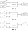
- FIG. 9 is a schematic diagram of a first structure of a node device. As shown in FIG. 9 , the node device includes a processor, a memory and a transceiver.
- a processor 900 is configured to read a program in a memory 920 to perform the following operations.
- a delay within the node device from a certain slot at an input port to another slot at an port is determined, where the node device is a node device on an end-to-end channel.
- a transceiver 910 is configured to receive and transmit data under the control of the processor 900.
- the operation of determining that the delay is used for establishing slot allocation on the end-to-end channel includes the following operations.
- the delay is transmitted to a centralized system; and/or an available slot for the node device is determined according to a slot with an optimal delay, and then the available slot is transmitted to a next node device on the channel.
- the determined delay is determined by the node device by itself; and/or the determined delay is determined upon reception of a request for determining the delay.
- the request for determining the delay is transmitted by a centralized system to node devices on a node device path after determining the node device path that the end-to-end channel passes through.
- the determined delay within the node device from the certain slot at the input port to the another slot at the port may be a delay value between other slots determined by the node device after the node device determines a delay within the node device from a certain slot A at an input port p to another slot B at an output port q.
- the delay value between other slots is determined based on a frame structure with slots and a pre-acquired node delay variation model.
- the method further includes the following operations.
- An available slot determined by a previous node device on the channel according to a slot with an optimal delay for the previous node device is received.
- An available slot for the node device is determined according to the slot with the optimal delay for the node device , and then the available slot for the node device is transmitted to the next node device on the channel.
- a bus architecture may include any number of interconnected buses and bridges, specifically one or more processors represented by the processor 900 and various circuits of memories represented by the memory 920 linked together.
- the bus architecture may also link various other circuits such as peripheral devices, regulators, and power management circuits together, which are well known in the art. Therefore, these content will not be further described herein.
- a bus interface provides interfaces.
- the transceiver 910 may be multiple components, including a transmitter and a receiver, providing a unit for communicating with various other devices on a transmission medium.
- the processor 900 is responsible for managing the bus architecture and general processing.
- the memory 920 may store data used by the processor 900 when performing operations.
- the embodiment of the disclosure further provides a node device, including a first determination module and a first transmission module.
- the first determination module is configured to determine a delay within the node device from a certain slot at an input port to another slot at an port, where the node device is a node device on an end-to-end channel.
- the first transmission module is configured to determine that the delay is used for establishing slot allocation on the end-to-end channel.
- the first transmission module is further configured to transmit the delay to a centralized system; and/or determine an available slot for the node device according to a slot with an optimal delay, and then transmit the available slot for the node device to a next node device on the channel.
- the first determination module is further configured to determine the delay by itself; and/or, determine the delay upon reception of a request for determining the delay.
- the first transmission module is further configured to transmit the request for determining the delay by a centralized system to node devices on a node device path after determining the node device path that the end-to-end channel passes through.
- the first determination module in determining the delay within the node device from the certain slot at the input port to the another slot at the port, may be further configured to determine a delay value between other slots after determining a delay within the node device from a certain slot A at an input port p to another slot B at an output port q..
- the first determination module is further configured to determine the delay value between other slots based on a frame structure with slots and a pre-acquired node delay variation model.
- the first transmission module may be further configured to receive an available slot determined by a previous node device on the channel according to a slot with an optimal delay for the previous node device, determine an available slot for the node device according to a slot with an optimal delay for the node device, and then transmit the available slot for the node device to a next node device on the channel.
- each part of the above device is divided into various modules or units according to their functions and described respectively.
- the functions of each module or unit may be implemented in the same or multiple software or hardware when implementing the disclosure.
- FIG. 10 is a a schematic diagram of a second structure of a node device. As shown in FIG. 10 , the node device includes a processor, a memory and a transceiver.
- a processor 1000 is configured to read a program in a memory 1020 to perform the following operations.
- An available slot determined by a previous node device on a channel according to a slot with an optimal delay for the previous node device is received.
- An available slot for a current node device is determined according to a slot with an optimal delay for the current node device,, and then the available slot for the current node device is transmitted to a next node device on the channel.
- determining delays of available slots comprises: for each of node devices, determining, by the node device, the delay within the node device from a certain slot at an input port to another slot at an port, wherein each of the node devices is a node device on an end-to-end channel, and the delays are used for establishing slot allocation on the end-to-end channel.
- a transceiver 1010 is configured to receive and transmit data under the control of the processor 1000.
- the determined delay is determined by the node device by itself; and/or the determined delay is determined upon reception of a request for determining the delay.
- the request for determining the delay is transmitted by a centralized system to the node devices on a node device path after determining the node device path that the end-to-end channel passes through.
- the determined delay within the node device from the certain slot at the input port to the another slot at the port is a determined delay value between other slots after the node device determines a delay within a node from a certain slot A at an input port p to another slot B at an output port q.
- the delay value between other slots is determined based on a frame structure with slots and a pre-acquired node delay variation model.
- a bus architecture may include any number of interconnected buses and bridges, specifically one or more processors represented by the processor 1000 and various circuits of memories represented by the memory 1020 linked together.
- the bus architecture may also link various other circuits such as peripheral devices, regulators, and power management circuits together, which are well known in the art. Therefore, these content will not be further described herein.
- a bus interface provides interfaces.
- the transceiver 1010 may be multiple components, including a transmitter and a receiver, providing a unit for communicating with various other devices on a transmission medium.
- the processor 1000 is responsible for managing the bus architecture and general processing.
- the memory 1020 may store data used by the processor 1000 when performing operations.
- the embodiment of the disclosure further provides a node device, including a first reception module and a second transmission module.
- the first reception module is configured to receive an available slot determined by a previous node device on a channel according to a slot with an optimal delay for the previous node device.
- the second transmission module is configured to determine an available slot for a current node device according to a slot with an optimal delay for the current node device, and then transmit the available slot for the current node device to a next node device on the channel.
- determining delays of available slots comprises: for each of node devices, determining, by the node device, the delay within the node device from a certain slot at an input port to another slot at an port, wherein each of the node devices is a node device on an end-to-end channel, and the delays are used for establishing slot allocation on the end-to-end channel.
- the second transmission module is further configured to determine the delay by itself; and/or determine the delay upon reception of a request for determining the delay.
- the second transmission module is further configured to transmit the request for determining the delay by a centralized system to the node devices on a node device path after determining the node device path that the end-to-end channel passes through.
- the second transmission module in determining the delay within the node device from the certain slot at the input port to the another slot at the port, may be further configured to determine a delay value between other slots after the node device determines a delay within the node device from a certain slot A at an input port p to another slot B at an output port q.
- the second transmission module is further configured to determine the delay value between other slots based on a frame structure with slots and a pre-acquired node delay variation model.
- each part of the above device is divided into various modules or units according to their functions and described respectively.
- the functions of each module or unit may be implemented in the same or multiple software or hardware when implementing the disclosure.
- FIG. 11 is a schematic diagram of a third structure of a node device. As shown in FIG. 11 , the node device includes a processor, a memory and a transceiver.
- a processor 1100 is configured to read a program in a memory 1120 to perform the following operations.
- An available slot determined by a previous node device on a channel according to a slot with an optimal delay for the previous node device is received.
- An available slot for a current node device is determined according to a slot with an optimal delay for the current node device, and then slot allocation is performed on an end-to-end channel according to respective available slots for node devices.
- determining delays of available slots comprises: for each of the node devices, determining, by the node device, the delay within the node device from a certain slot at an input port to another slot at an port, each of the node devices is a node device on the end-to-end channel, and the delays are used for establishing the slot allocation on the end-to-end channel.
- a transceiver 1110 is configured to receive and transmit data under the control of the processor 1100.
- the determined delay is determined by the node device by itself; and/or the determined delay is determined upon reception of a request for determining the delay.
- the request for determining the delay is transmitted by a centralized system to the node devices on a node device path after determining the node device path that the end-to-end channel passes through.
- the determined delay within the node device from the certain slot at the input port to the another slot at the port is a determined delay value between other slots after the node device determines a delay within a node from a certain slot A at an input port p to another slot B at an output port q.
- the delay value between other slots is determined based on a frame structure with slots and a pre-acquired node delay variation model to determine the delay value between other slots.
- a bus architecture may include any number of interconnected buses and bridges, specifically one or more processors represented by the processor 1100 and various circuits of memories represented by the memory 1120 linked together.
- the bus architecture may also link various other circuits such as peripheral devices, regulators, and power management circuits together, which are well known in the art. Therefore, these content will not be further described herein.
- a bus interface provides interfaces.
- the transceiver 1110 may be multiple components, including a transmitter and a receiver, providing a unit for communicating with various other devices on a transmission medium.
- the processor 1100 is responsible for managing the bus architecture and general processing.
- the memory 1120 may store data used by the processor 1100 when performing operations.
- the embodiment of the disclosure further provides a node device, including a second reception module and a first allocation module.
- the second reception module is configured to receive an available slot determined by a previous node device on a channel according to a slot with an optimal delay for the previous node device.
- the first allocation module is configured to determine an available slot for a current node device according to a slot with an optimal delay for the current node device, and then perform slot allocation on an end-to-end channel according to respective available slots for node devices.
- Determining delays of available slots comprises: for each of node devices, determining, by the node device, the delay within the node device from a certain slot at an input port to another slot at an port, wherein each of the node devices is a node device on an end-to-end channel, and the delays are used for establishing slot allocation on the end-to-end channel.
- the first allocation module is further configured to determine the delay by itself; and/or determine the delay after receiving a request for determining the delay.
- the first allocation module is further configured to transmit the request for determining the delay by a centralized system to the node devices on a node device path after determining the node device path that the end-to-end channel passes through.
- the first allocation module in determining the delay within the node device from the certain slot at the input port to the another slot at the port, may be further configured to determine a delay value between other slots after the node device determines a delay within the node device from a certain slot A at an input port p to another slot B at an output port q.
- the first allocation module is further configured to determine the delay value between other slots based on the frame structure with slots and the pre-acquired node delay variation model.
- each part of the above device is divided into various modules or units according to their functions and described respectively.
- the functions of each module or unit may be implemented in the same or multiple software or hardware when implementing the disclosure.
- FIG. 12 is a schematic structural diagram of a centralized system. As shown in FIG. 12 , the centralized system includes a processor, a memory and a transceiver.
- a processor 1200 is configured to read a program in a memory 1220 to perform the following operations.
- Delays transmitted by node devices are received, where for each of the node devices, the delay is a delay within the node device from a certain slot at an input port to another slot at an port determined by the node device, each of the node devices is a node device on an end-to-end channel, and the delays are used for establishing slot allocation on the end-to-end channel.
- the slot allocation on the end-to-end channel is performed according to each delays.
- a transceiver 1210 is configured to receive and transmit data under the control of the processor 1200.
- the determined delay is determined by the node device by itself; and/or the determined delay is determined upon reception of a request for determining the delay.
- the method further includes the following operations.
- a node device path that the end-to-end channel passes through is determined, and then the request for determining the delay is transmitted to the node device on the node device path.
- the operation of performing the slot allocation on the end-to-end channel according to the delay includes the following operations.
- a slot with an optimal delay within each node device is determined as an available slot for the node device successively in a direction from a source node device to a destination node device in sequence, and the slot allocation is performed according to the determined available slots.
- a bus architecture may include any number of interconnected buses and bridges, specifically one or more processors represented by the processor 1200 and various circuits of memories represented by the memory 1220 linked together.
- the bus architecture may also link various other circuits such as peripheral devices, regulators, and power management circuits together, which are well known in the art. Therefore, these content will not be further described herein.
- a bus interface provides interfaces.
- the transceiver 1210 may be multiple components, including a transmitter and a receiver, providing a unit for communicating with various other devices on a transmission medium.
- the processor 1200 is responsible for managing the bus architecture and general processing.
- the memory 1220 may store data used by the processor 1200 when performing operations.
- the embodiment of the disclosure further provides a centralized system, including a third reception module and a second allocation module.
- the third reception module is configured to receive delays transmitted by node devices, wherein for each of the node devices, the delay is a delay within the node device from a certain slot at an input port to another slot at an port determined by the node device, each of the node devices is a node device on an end-to-end channel, and the delays are used for establishing slot allocation on the end-to-end channel.
- the second allocation module is configured to perform slot allocation on the end-to-end channel according to the delays.
- the third reception module is further configured to receive the delay determined by the node device by itself; and/or receive the determined delay upon reception of a request for determining the delay.
- the third reception module is further configured to determine a node device path that the end-to-end channel passes through, and then transmit the request for determining the delay to the node device on the node device path.
- the second allocation module in performing the slot allocation on the end-to-end channel according to the delays, may be further configured to determine a slot with an optimal delay within each node device as an available slot for the node device successively in a direction from a source node device to a destination node device, and perform the slot allocation according to the determined available slots.
- each part of the above device is divided into various modules or units according to their functions and described respectively.
- the functions of each module or unit may be implemented in the same or multiple software or hardware when implementing the disclosure.
- the embodiment of the disclosure further provides a computer-readable storage medium, having stored thereon a computer program, the computer program executes the above methods for processing slot allocation.
- a node device determines a delay within the node device from a certain slot at an input port to another slot at an port, and takes the delay information as an condition for establishing slot allocation on an end-to-end channel.
- the technical solution further provides the following operations.
- the node device determines the delay by itself, or the node device determines the delay after receiving a request.
- a centralized system determines a channel path, and then requests the delay within each of the nodes between corresponding ports of the respective node on the determined path, from the slot at the input port to the slot at the output port of the respective node.
- the centralized system obtains all delay information on the path, and determines available slot allocation with an optimal delay within each node device successively in a direction from a source node to a destination node. After determining the slots, the centralized system performs slot allocation based on the determined slots and establishes a channel.
- the slot allocation may also be determined by each node, and then transmitted to the next node through a message, so as to successively determine an available slot allocation with the optimal delay within each node device.
- the node device determines a delay within the node device from a certain slot A at an input port p to another slot B at an output port q, and then calculates the delay value between other slots based on a frame structure with slots and a pre-acquired node delay variation model
- the scheme proposes a set of schemes of effective end-to-end channel establishment, including slot allocation, which can optimize the delay caused by the slot allocation on a channel and reduce the delay on the end-to-end channel.
- the embodiment of the disclosure may be provided as methods, systems or computer program products. Therefore, the disclosure may take the form of embodiments with entirely hardware, embodiments with entirely software, or embodiments combining software and hardware aspects. Furthermore, the disclosure may take the form of a computer program product implemented on one or more computer available storage media (including, but not limited to, disk storages, optical storages, etc.) containing computer available program code therein.
- These computer program instructions may also be stored in a computer-readable memory that may guide a computer or other programmable data processing device to operate in a specific manner such that the instructions stored in the computer-readable memory generate a manufacture including instruction devices, and the instruction devices implement functions specified in one or more flows of the flowcharts and/or one or more blocks of the block diagrams.
- These computer program instructions may also be loaded onto a computer or other programmable data processing device such that a series of operations are executed on the computer or other programmable device to generate computer-implemented processing, and the instructions executed on the computer or other programmable device provide operations for implementing functions specified in one or more flows of the flowcharts and/or one or more blocks of the block diagrams.
Landscapes
- Engineering & Computer Science (AREA)
- Computer Networks & Wireless Communication (AREA)
- Signal Processing (AREA)
- Environmental & Geological Engineering (AREA)
- Small-Scale Networks (AREA)
- Data Exchanges In Wide-Area Networks (AREA)
Abstract
Description
- This application is filed based on and claims priority to
Chinese Patent application No. 202110235233.X filed on March 3, 2021 - The disclosure relates to the technical field of communications, and in particular to a method for processing slot allocation, a device and a storage medium.
- With the development of 5G and the increase of users in vertical industries, the demand for slicing in the network has increased. A lot of beneficial exploration in the slicing isolation technology based on Ethernet has been made in the industry. For example, the flex Ethernet (FlexE) technology dominated by Optical Internet Forum (OIF) provides a fragmentation mechanism based on the Ethernet physical interface, which may provide an effective interface-level isolation mechanism. However, FlexE is just an interface-level technology at present, which cannot meet the networking requirements of operators networks. Metro transport network (MTN) is a new transmission network technology system defined by ITU-Telecommunication standardization sector (ITU-T) for new service requirements such as 5G, which may realize the effective integration of time division multiplexing (TDM) and packet switching. MTN is composed of a section layer and a path layer. A MTN section layer supports slot division and port binding, and is compatible with Ethernet underlying protocol stack and standard Ethernet optical module. A path layer of metro transmission network supports TDM switching based on 66B code blocks, has a comprehensive end-to-end operation administration and maintenance (OAM) mechanism, and supports cross-multiplexing of channelized customer signals with any Nx5G or smaller bandwidth particles.
- The deficiency of the related art is that the current method for establishing an end-to-end slicing channel will increase a processing delay within a node due to the method for slot allocation.
- The disclosure provides a method for processing slot allocation, a device and a storage medium to solve the problem of an increasing processing delay within a node due to the method for slot allocation.
- The disclosure provides the following technical solutions.
- A method for processing slot allocation, including the following operations.
- A node device determines a delay within the node device from a certain slot at an input port to another slot at an port, where the node device is a node device on an end-to-end channel.
- The node device determines that the delay is used for establishing slot allocation on the end-to-end channel.
- In some optional embodiments, the operation that the node device determines the delay for establishing the slot allocation on the end-to-end channel may include the following operations.
- The node device transmits the delay to a centralized system; and/or the node device determines an available slot for the node device according to a slot with an optimal delay, and then transmits the available slot for the node device to a next node device on the channel.
- In some optional embodiments, the delay determined by the node device may be determined by the node device by itself; and/or the delay determined by the node device may be determined upon reception of a request for determining the delay.
- In some optional embodiments, the request for determining the delay may be transmitted by a centralized system to node devices on a node device path after determining the node device path that the end-to-end channel passes through.
- In some optional embodiments, the delay within the node device from the certain slot at the input port to the another slot at the port determined by the node device may be a delay value between other slots determined by the node device after the node device determines a delay within the node device from a certain slot A at an input port p to another slot B at an output port q.
- In some optional embodiments, the delay value between other slots may be determined based on a frame structure with slots and a pre-acquired node delay variation model.
- In some optional embodiments, the method may further include the following operations.
- An available slot determined by a previous node device on the channel according to a slot with an optimal delay for the previous node device is received.
- An available slot for the node device is determined according to a slot with an optimal delay for the node device, and then the available slot for the node device is transmitted to the next node device on the channel.
- A method for processing slot allocation, includes the following operations.
- An available slot determined by a previous node device on a channel according to a slot with an optimal delay for the previous node device is received.
- An available slot for a current node device is determined according to a slot with an optimal delay for the current node device, and then the available slot for the current node device is transmitted to a next node device on the channel.
- Where determining delays of available slots comprises: for each of node devices, determining, by the node device, the delay within the node device from a certain slot at an input port to another slot at an port, wherein each of the node devices is a node device on an end-to-end channel, and the delays are used for establishing slot allocation on the end-to-end channel.
- In some optional embodiments, the delay determined by the node device may be determined by the node device by itself; and/or the delay determined by the node device may be determined upon reception of a request for determining the delay.
- In some optional embodiments, the request for determining the delay may be transmitted by a centralized system to the node devices on a node device path after determining the node device path that the end-to-end channel passes through.
- In some optional embodiments, the delay within the node device from the certain slot at the input port to the another slot at the port determined by the node device may be a delay value between other slots determined by the node device after the node device determines a delay within a node from a certain slot A at an input port p to another slot B at an output port q.
- In some optional embodiments, the delay value between other slots may be determined based on a frame structure with slots and a pre-acquired node delay variation model.
- A method for processing slot allocation, includes the following operations.
- An available slot determined by a previous node device on a channel according to a slot with an optimal delay for the previous node device is received.
- An available slot for a current node device is determined according to a slot with an optimal delay for the current node device, and then slot allocation is performed on an end-to-end channel according to respective available slots for node devices.
- Where determining delays of available slots comprises: for each of the node devices, determining, by the node device, the delay within the node device from a certain slot at an input port to another slot at an port, each of the node devices is a node device on the end-to-end channel, and the delays are used for establishing the slot allocation on the end-to-end channel.
- In some optional embodiments, the delay determined by the node device may be determined by the node device by itself; and/or the delay determined by the node device may be determined upon reception of a request for determining the delay.
- In some optional embodiments, the request for determining the delay may be transmitted by a centralized system to the node devices on a node device path after determining the node device path that the end-to-end channel passes through.
- In some optional embodiments, the delay within the node device from the certain slot at the input port to the another slot at the port determined by the node device may be a delay value between other slots determined by the node device after the node device determines a delay within a node from a certain slot A at an input port p to another slot B at an output port q.
- In some optional embodiments, the delay value between other slots may be determined based on a frame structure with slots and a pre-acquired node delay variation model.
- A method for processing slot allocation, includes the following operations.
- Delays transmitted by node devices are received, where for each of the node devices, the delay is a delay within the node device from a certain slot at an input port to another slot at an port determined by the node device, each of the node devices is a node device on an end-to-end channel, and the delays are used for establishing slot allocation on the end-to-end channel.
- The slot allocation is performed on the end-to-end channel according to the delays.
- In some optional embodiments, the delay determined by the node device may be determined by the node device by itself; and/or the delay determined by the node device may be determined upon reception of a request for determining the delay.
- In some optional embodiments, the method may further include the following operations.
- A node device path that the end-to-end channel passes through is determined, and then the request for determining the delays is transmitted to the node devices on the node device path.
- In some optional embodiments, the operation that the slot allocation on the end-to-end channel is performed according to the delays may include the following operations.
- A slot with an optimal delay within each node device is determined as an available slot for the node device successively in a direction from a source node device to a destination node device, and the slot allocation is performed according to the determined available slots.
- A node device, including a processor and a transceiver.
- The processor is configured to read a program in a memory to perform the following operations.
- A delay within the node device from a certain slot at an input port to another slot at an port is determined, where the node device is a node device on an end-to-end channel.
- It is determined that the delay is used for establishing slot allocation on the end-to-end channel.
- The transceiver is configured to receive and transmit data under the control of the processor.
- In some optional embodiments, the operation of determining that the delay is used for establishing slot allocation on the end-to-end channel may include the following operations.
- The delay is transmitted to a centralized system; and/or an available slot for the node device is determined according to a slot with an optimal delay, and then the available slot is transmitted to a next node device on the channel.
- In some optional embodiments, the determined delay may be determined by the node device by itself; and/or the determined delay may be determined upon reception of a request for determining the delay.
- In some optional embodiments, the request for determining the delay may be transmitted by a centralized system to node devices on a node device path after determining the node device path that the end-to-end channel passes through.
- In some optional embodiments, the determined delay within the node device from the certain slot at the input port to the another slot at the port may be a delay value between other slots determined by the node device after the node device determines a delay within the node device from a certain slot A at an input port p to another slot B at an output port q.
- In some optional embodiments, the delay value between other slots may be determined based on a frame structure with slots and a pre-acquired node delay variation model.
- In some optional embodiments, the method may further include the following operations.
- An available slot determined by a previous node device on the channel according to a slot with an optimal delay for the previous node device is received.
- An available slot for the node device is determined according to the slot with the optimal delay for the node device , and then the available slot for the node device is transmitted to the next node device on the channel.
- A node device, includes a first determination module and a first transmission module.
- The first determination module is configured to determine a delay within the node device from a certain slot at an input port to another slot at an port, where the node device is a node device on an end-to-end channel.
- The first transmission module is configured to determine that the delay is used for establishing slot allocation on the end-to-end channel.
- In some optional embodiments, the first transmission module may be further configured to transmit the delay to a centralized system; and/or determine an available slot for the node device according to a slot with an optimal delay, and then transmit the available slot for the node device to a next node device on the channel.
- In some optional embodiments, the first determination module may be further configured to determine the delay by itself; and/or, determine the delay upon reception of a request for determining the delay.
- In some optional embodiments, the first transmission module may be further configured to transmit the request for determining the delay by a centralized system to node devices on a node device path after determining the node device path that the end-to-end channel passes through.
- In some optional embodiments, in determining the delay within the node device from the certain slot at the input port to the another slot at the port, the first determination module may be further configured to determine a delay value between other slots after determining a delay within the node device from a certain slot A at an input port p to another slot B at an output port q.
- In some optional embodiments, the first determination module may be further configured to determine the delay value between other slots based on a frame structure with slots and a pre-acquired node delay variation model.
- In some optional embodiments, the first transmission module may be further configured to receive an available slot determined by a previous node device on the channel according to a slot with an optimal delay for the previous node device, determine an available slot for the node device according to a slot with an optimal delay for the node device, and then transmit the available slot for the node device to a next node device on the channel.
- A node device, includes a processor and a transceiver.
- The processor is configured to read a program in a memory to perform the following operations.
- An available slot determined by a previous node device on a channel according to a slot with an optimal delay for the previous node device is received.
- An available slot for a current node device is determined according to a slot with an optimal delay for the current node device,, and then the available slot for the current node device is transmitted to a next node device on the channel.
- Where determining delays of available slots comprises: for each of node devices, determining, by the node device, the delay within the node device from a certain slot at an input port to another slot at an port, wherein each of the node devices is a node device on an end-to-end channel, and the delays are used for establishing slot allocation on the end-to-end channel.
- The transceiver is configured to receive and transmit data under control of the processor.
- In some optional embodiments, the determined delay may be determined by the node device by itself; and/or the determined delay may be determined upon reception of a request for determining the delay.
- In some optional embodiments, the request for determining the delay may be transmitted by a centralized system to the node devices on a node device path after determining the node device path that the end-to-end channel passes through.
- In some optional embodiments, the determined delay within the node device from the certain slot at the input port to the another slot at the port may be a determined delay value between other slots after the node device determines a delay within a node from a certain slot A at an input port p to another slot B at an output port q.
- In some optional embodiments, the delay value between other slots may be determined based on a frame structure with slots and a pre-acquired node delay variation model.
- A node device, includes a first reception module and a second transmission module.
- The first reception module is configured to receive an available slot determined by a previous node device on a channel according to a slot with an optimal delay for the previous node device.
- The second transmission module is configured to determine an available slot for a current node device according to a slot with an optimal delay for the current node device, and then transmit the available slot for the current node device to a next node device on the channel.
- Where determining delays of available slots comprises: for each of node devices, determining, by the node device, the delay within the node device from a certain slot at an input port to another slot at an port, wherein each of the node devices is a node device on an end-to-end channel, and the delays are used for establishing slot allocation on the end-to-end channel.
- In some optional embodiments, the second transmission module may be further configured to determine the delay by itself; and/or determine the delay upon reception of a request for determining the delay.
- In some optional embodiments, the second transmission module may be further configured to transmit the request for determining the delay by a centralized system to the node devices on a node device path after determining the node device path that the end-to-end channel passes through.
- In some optional embodiments, in determining the delay within the node device from the certain slot at the input port to the another slot at the port, the second transmission module may be further configured to determine a delay value between other slots after the node device determines a delay within the node device from a certain slot A at an input port p to another slot B at an output port q.
- In some optional embodiments, the second transmission module may be further configured to determine the delay value between other slots based on a frame structure with slots and a pre-acquired node delay variation model.
- A node device, including a processor and a transceiver.
- The processor is configured to read a program in a memory to perform the following operations.
- An available slot determined by a previous node device on a channel according to a slot with an optimal delay for the previous node device is received.
- An available slot for a current node device is determined according to a slot with an optimal delay for the current node device, and then slot allocation is performed on an end-to-end channel according to respective available slots for node devices.
- Where determining delays of available slots comprises: for each of the node devices, determining, by the node device, the delay within the node device from a certain slot at an input port to another slot at an port, each of the node devices is a node device on the end-to-end channel, and the delays are used for establishing the slot allocation on the end-to-end channel.
- The transceiver is configured to receive and transmit data under control of the processor.
- In some optional embodiments, the determined delay may be determined by the node device by itself; and/or the determined delay may be determined upon reception of a request for determining the delay.
- In some optional embodiments, the request for determining the delay may be transmitted by a centralized system to the node devices on a node device path after determining the node device path that the end-to-end channel passes through.
- In some optional embodiments, the determined delay within the node device from the certain slot at the input port to the another slot at the port may be a determined delay value between other slots after the node device determines a delay within a node from a certain slot A at an input port p to another slot B at an output port q.
- In some optional embodiments, the delay value between other slots may be determined based on a frame structure with slots and a pre-acquired node delay variation model.
- A node device, includes a second reception module and a first allocation module.
- The second reception module is configured to receive an available slot determined by a previous node device on a channel according to a slot with an optimal delay for the previous node device.
- The first allocation module is configured to determine an available slot for a current node device according to a slot with an optimal delay for the current node device, and then perform slot allocation on an end-to-end channel according to respective available slots for node devices.
- Where determining delays of available slots comprises: for each of node devices, determining, by the node device, the delay within the node device from a certain slot at an input port to another slot at an port, wherein each of the node devices is a node device on an end-to-end channel, and the delays are used for establishing slot allocation on the end-to-end channel.
- In some optional embodiments, the first allocation module may be further configured to determine the delay by itself; and/or determine the delay after receiving a request for determining the delay.
- In some optional embodiments, the first allocation module may be further configured to transmit the request for determining the delay by a centralized system to the node devices on a node device path after determining the node device path that the end-to-end channel passes through.
- In some optional embodiments, in determining the delay within the node device from the certain slot at the input port to the another slot at the port, the first allocation module may be further configured to determine a delay value between other slots after the node device determines a delay within the node device from a certain slot A at an input port p to another slot B at an output port q.
- In some optional embodiments, the first allocation module may be further configured to determine the delay value between other slots based on a frame structure with slots and a pre-acquired node delay variation model.
- A centralized system, includes a processor and a transceiver.
- The processor is configured to read a program in a memory to perform the following operations.
- Delays transmitted by node devices are received, where for each of the node devices, the delay is a delay within the node device from a certain slot at an input port to another slot at an port determined by the node device, each of the node devices is a node device on an end-to-end channel, and the delays are used for establishing slot allocation on the end-to-end channel.
- The slot allocation on the end-to-end channel is performed according to the delays.
- The transceiver is configured to receive and transmit data under control of the processor.
- In some optional embodiments, the determined delay may be determined by the node device by itself; and/or the determined delay may be determined upon reception of a request for determining the delay.
- In some optional embodiments, the method may further include the following operations.
- A node device path that the end-to-end channel passes through is determined, and then the request for determining the delay is transmitted to the node devices on the node device path.
- In some optional embodiments, the operation of performing the slot allocation on the end-to-end channel according to the delays may include the following operations.
- A slot with an optimal delay within each node device is determined as an available slot for the node device successively in a direction from a source node device to a destination node device, and the slot allocation is performed according to the determined available slots.
- A centralized system, including a third reception module and a second allocation module.
- The third reception module is configured to receive delays transmitted by node devices, wherein for each of the node devices, the delay is a delay within the node device from a certain slot at an input port to another slot at an port determined by the node device, each of the node devices is a node device on an end-to-end channel, and the delays are used for establishing slot allocation on the end-to-end channel.
- The second allocation module is configured to perform slot allocation on the end-to-end channel according to the delays.
- In some optional embodiments, the third reception module may be further configured to receive the delay determined by the node device by itself; and/or receive the determined delay upon reception of a request for determining the delay.
- In some optional embodiments, the third reception module may be further configured to determine a node device path that the end-to-end channel passes through, and then transmit the request for determining the delay to the node devices on the node device path.
- In some optional embodiments, in performing the slot allocation on the end-to-end channel according to the delays, the second allocation module may be further configured to determine a slot with an optimal delay within each node device as an available slot for the node device successively in a direction from a source node device to a destination node device, and perform the slot allocation according to the determined available slots.
- A computer-readable storage medium, having stored thereon a computer program, the computer program executes the above methods for processing slot allocation.
- The disclosure has the following beneficial effects.
- In the technical solutions provided in the embodiments of the disclosure, the node device determines the delay within the node device from a certain slot at an input port to another slot at an port. Due to considering the delay information as an input condition for establishing the slot allocation on the end-to-end channel when performing the slot allocation, the delay caused by the slot allocation on one channel is reduced, and the delay on the end-to-end channel is reduced.
- The drawings illustrated herein are intended to provide a further understanding of the disclosure and constitute a part of the disclosure. The illustrative embodiments of the disclosure and the description thereof are used to explain the disclosure and do not constitute an improper limitation of the disclosure.
-
FIG. 1 is a schematic diagram of slot allocation on an end-to-end channel in the embodiment of the disclosure. -
FIG. 2 is a schematic diagram of an impact of slot selection on a node delay in the embodiment of the disclosure. -
FIG. 3 is a schematic diagram of an implementation flow of a method for processing slot allocation in the embodiment of the disclosure. -
FIG. 4 is a schematic diagram of a channel path establishment in the embodiment of the disclosure. -
FIG. 5 is a schematic diagram of an implementation flow of a method for processing slot allocation on a centralized system in the embodiment of the disclosure. -
FIG. 6 is a schematic diagram of an implementation flow of a method for processing slot allocation on an intermediate node device side in the embodiment of the disclosure. -
FIG. 7 is a schematic diagram of an implementation flow of a method for processing slot allocation on a destination node device side in the embodiment of the disclosure. -
FIG. 8 is a schematic diagram of a process of successively determining optimal slots in the embodiment of the disclosure. -
FIG. 9 is a schematic diagram of a first structure of a node device in the embodiment of the disclosure. -
FIG. 10 is a schematic diagram of a second structure of a node device in the embodiment of the disclosure. -
FIG. 11 is a schematic diagram of a third structure of a node device in the embodiment of the disclosure. -
FIG. 12 is a schematic structural diagram of a centralized system in the embodiment of the disclosure. - The inventor noticed the following situations during the invention process.
- In order to establish an end-to-end channel, for example, from a source node NE1 to a destination node NEn, a port slot is configured for each node, as shown in the following drawings. For example, if the end-to-end channel needs a bandwidth of 10 million bits per second (Mbps), and the minimum bandwidth granularity for each slot is a 10Mbps bandwidth, 1 slot needs to be configured for each node.
FIG. 1 is a schematic diagram of slot allocation on an end-to-end channel. As shown inFIG. 1 , an output port configured for NE1 uses a m-th slot (slot m), an output port configured for NE2 uses a n-th slot (slot n), and an output port configured for NE3 uses the q-th slot (slot q). When the slots for all nodes on the end-to-end channel are allocated, the end-to-end slot channel can be established. - In the related art, the slot allocation is completed once. The slot allocation for each node in a channel mainly considers availability, and a required number of slots may be allocated from available slot resources for each node port.
- However, with the decrease of slot bandwidth, the processing delay within the node increases accordingly. Node processing delay has become a factor that has to be paid attention to. How to reduce the processing delay? There is a significant factor in the delay, which is related to slot allocation.
FIG. 2 is a schematic diagram of an impact of slot selection on a node delay. For example, as shown inFIG. 2 , assuming that a slot structure of a 10 million (M) slice granularity for a slicing packet network (SPN) is adopted, there are 480 slots to choose in a calendar slot of 5G. Choosing a first slot or a last slot or other slot in the 480 slots has a significant impact on the node delay. Assuming that a certain input slot channel needs to be sent out after completing a crossover within the node, and it happens to match the first slot in the 480 slots, and the selected output slot is also the first slot, then the delay is the shortest. Assuming that the first slot of the 480 slots is matched to the sending out, but the selected output slot is the last slot of the 480 slots, it has to wait until the last slot comes, to fill and transmit, in this case, the delay is relatively long. - Based on this, the embodiment of the disclosure proposes a new scheme for establishing slot allocation on the end-to-end channel, which can optimize the delay caused by the slot allocation in a channel and meet the technical and application requirements.
- Specific implementation of the disclosure is described below with reference to the drawings.
- In the description, the implementation of a source node device side, an intermediate node device side, a destination node device side and a centralized system (e.g., a management and control system) side involved in the end-to-end channel will be explained respectively, and then embodiments of their cooperation will be provided to better understand the implementation of the scheme provided in the embodiment of the disclosure. This explanation does not mean that they must be implemented together or separately. In fact, when they are implemented separately, they also solve their own problems, and when they are used together, they will get better technical results.
- In the embodiments of the disclosure, two schemes are provided for the slot allocation, one is implemented by the centralized system, and the other is implemented by each node device. The embodiment of the node device for determining and transmitting the delay will be explained in
FIG. 3 , the scheme performed by the centralized system will be explained inFIG. 5 , and the allocation scheme performed by each node device will be explained inFIG. 6 (the intermediate node device) andFIG. 7 (the destination node device). -
FIG. 3 is a schematic diagram of an implementation flow of a method for processing slot allocation, as shown inFIG. 3 , the method may include the followingoperations 301 to 302. - At 301, a node device determines a delay within the node device from a certain slot at an input port to another slot at an port, where the node device is a node device on an end-to-end channel.
- At 302, the node device determines that the delay is used for establishing slot allocation on the end-to-end channel.
- In some optional embodiments, the operation that the node device determines that the delay is used for establishing slot allocation on the end-to-end channel includes the following operations.
- The node device transmits the delay to a centralized system; and/or the node device determines an available slot for the node device according to a slot with an optimal delay, and then transmits the available slot for the node device to a next node device on the channel.
- In some optional embodiments, the node device determines the delay within the node device from the certain slot at the input port to the another slot at the port and takes the delay information as an input condition for establishing the slot allocation on the end-to-end channel.
- Specifically, in implementation, when the node device detects a specific mark of a certain slot at an input port, the node device records a time stamp. When detecting a mark of a certain slot at an output port, the node device records another time stamp. By performing a subtracting operation on the two time stamp values, the delay from the slot at the input port to another slot at the output port may be obtained.
- In some optional embodiments, the delay determined by the node device is determined by the node device by itself; and/or the delay determined by the node device is determined upon reception of a request for determining the delay.
- Specifically, the node device determines the delay by itself, or the node device determines the delay upon reception of the request.
- The node device may determine the delay within the node from a certain slot at an input port to another slot at an port (for example, when the device is started) by itself, or the node device starts to determine the delay within the node device from a certain slot at an input port of the node to another slot at the port upon receiving a request.
- In some optional embodiments, the request for determining the delay is transmitted by a centralized system to node devices on a node device path after determining the node device path that the end-to-end channel passes through.
- Specifically, after the centralized system determines the channel path, the centralized system requests the delay within each of the nodes between corresponding ports of the respective node on the determined path, from the slot at the input port to the slot at the output port of the respective node.
-
FIG. 4 is a schematic diagram of a channel path establishment. As shown inFIG. 4 , the request may be received as follows: after a centralized system (e.g., a management and control system) determines to establish an end-to-end channel with a certain bandwidth from a node m to another node n, the centralized system calculates and determines a path from the node m to the node n based on network information (such as network topology, available slot resources of nodes, etc.), including information of intermediate nodes, an input port and an output port of each node, and then the centralized system requests the delay within each of the nodes between corresponding ports of the respective node on the determined path, from the slot at the input port to the slot at the output port. - The delay within the node device from the certain slot at the input port to the another slot at the port determined by the node device is a delay value between other slots determined by the node device after the node device determines a delay within the node device from a certain slot A at an input port p to another slot B at an output port q.
- In some optional embodiments, the delay value between other slots is determined based on a frame structure with slots and a pre-acquired node delay variation model.
- Specifically, after the node device determines the delay within the node device from the certain slot A at the input port p to the another slot B at the output port q, the delay value between other slots is calculated based on the frame structure with slots and the pre-acquired node delay variation model.
- After the node device determines the delay within the node device from the certain slot A at the input port p to the another slot B at the output port q, the delay within the node devices from another slot (e.g., slot C) at the port p to another slot (e.g., slot D) at the port q does not need to be tested and determined one by one. It may be calculated according to the delay value from the slot A at the input port p to the slot B at the output port q, the frame structure with slots and the pre-acquired node delay variation model.
- Explanations will be given in the below respectively.
- 1. The slot allocation is performed by a centralized system.
-
FIG. 5 is a schematic diagram of an implementation flow of a method for processing slot allocation on a centralized system. As shown inFIG. 5 , the method may include the followingoperations 501 to 502. - At 501, delays transmitted by node devices are received, where for each of the node devices, the delay is a delay within the node device from a certain slot at an input port to another slot at an port determined by the node device, each of the node devices is a node device on an end-to-end channel, and the delays are used for establishing slot allocation on the end-to-end channel.
- At 502, the slot allocation on the end-to-end channel is performed according to the delays.
- In some optional embodiments, the delay determined by the node device is determined by the node device by itself; and/or the delay determined by the node device is determined upon reception of a request for determining the delay.
- In some optional embodiments, the method may further include the following operations.
- A node device path that the end-to-end channel passes through is determined, and then the request for determining the delay is transmitted to the node device on the node device path.
- In some optional embodiments, the operation that the slot allocation on the end-to-end channel is performed according to each delay includes the following operations.
- A slot with an optimal delay within each node device is determined as an available slot for the node device successively in a direction from a source node device to a destination node device, and the slot allocation is performed according to the determined available slots.
- The optimal delay is not necessarily the minimum delay, and the minimum delay is merely one of the cases, and there may be other strategies. In the allocation of available slots with the optimal delay for each node, the optimal delay may be the slot with the smallest delay or the slot with the second smallest delay considering a tolerance for certain jitter. Assuming that the slot with the smallest delay jitters and a phase changes being a bit earlier, the output may not be able to catch up with this slot, so it has to wait for one cycle and then put it into the same slot in the next cycle, and in this case, the delay will become relatively large.
- Specifically, the node device determines a delay within a node from a certain slot A at a input port p to an another slot B at a port q, and then the node device reports the delay to the centralized system. After the centralized system obtains all delay information on the path, it determines an available slot allocation with the optimal delay for each node successively in a direction from a source node to a destination node. After determining the slots, the centralized system performs slot allocation based on the determined slots and establishes a channel.
- 2. The slot allocation is performed by each node device.
- In the case of no centralized system or no need for a centralized system, the slot allocation may be determined by each node, and then transmitted to the next node through a message, so as to successively determine an available slot allocation with an optimal delay for each node.
-
FIG. 6 is a schematic diagram of an implementation flow of a method for processing slot allocation on an intermediate node device side. As shown inFIG. 6 , the method may include the followingoperations 601 to 602. - At 601, an available slot determined by a previous node device on a channel according to a slot with an optimal delay for the previous node device is received.
- At 602, an available slot for a current node device is determined according to a slot with an optimal delay for the current node device, and then the available slot for the current node device is transmitted to a next node device on the channel.
- Determining delays of available slots includes determining, by each of node devices, the delay within the node device from a certain slot at an input port to another slot at an port, each of the node devices is a node device on an end-to-end channel, and the delays are used establishing the slot allocation on the end-to-end channel.
-
FIG. 7 is a schematic diagram of an implementation flow of a method for processing slot allocation on a destination node device side. As shown inFIG. 7 , the method may include the followingoperations 701 to 702. - At 701, an available slot determined by a previous node device on a channel according to a slot with an optimal delay for the previous node device is received.
- At 702, an available slot for a current node device is determined according to a slot with the optimal delay for the current node device, and then slot allocation on an end-to-end channel is performed according to respective available slots for node devices.
- Determining delays of available slots includes determining, by each of node devices, the delay within the node device from a certain slot at an input port to another slot at an port, each of the node devices is a node device on the end-to-end channel, and the delays are used establishing the slot allocation on the end-to-end channel.
-
FIG. 8 is a schematic diagram of a process of successively determining optimal slots. As shown inFIG. 8 , in the above slot allocation process and the allocation of available slots with an optimal delay for each node, the optimal delay may be the slot with the smallest delay or the slot with the second smallest delay considering a tolerance for certain jitter. Assuming that the slot with the smallest delay jitters and a phase changes is a bit earlier, the output may not be able to catch up with this slot, so it has to wait for one cycle and then put it into the same slot in next cycle, and in this case, the delay will become relatively large. - For bidirectional channels, the above process may be independently performed in both directions to determine the adopted slots respectively.
- Based on the same inventive concept, the embodiment of the disclosure further provides a node device, a centralized system, and a computer-readable storage medium. Since a principle of solving the problem by these devices is similar to the method for processing slot allocation on the node device and the centralized system, the implementation of these devices may refer to the implementation of the method, and the repetition will not be repeated.
- When implementing the technical solution provided by the embodiment of the disclosure, it may be implemented in the following manner.
-
FIG. 9 is a schematic diagram of a first structure of a node device. As shown inFIG. 9 , the node device includes a processor, a memory and a transceiver. - A
processor 900 is configured to read a program in amemory 920 to perform the following operations. - A delay within the node device from a certain slot at an input port to another slot at an port is determined, where the node device is a node device on an end-to-end channel.
- It is determined that the delay is used for establishing slot allocation on the end-to-end channel.
- A
transceiver 910 is configured to receive and transmit data under the control of theprocessor 900. - In some optional embodiments, the operation of determining that the delay is used for establishing slot allocation on the end-to-end channel includes the following operations.
- The delay is transmitted to a centralized system; and/or an available slot for the node device is determined according to a slot with an optimal delay, and then the available slot is transmitted to a next node device on the channel.
- In some optional embodiments, the determined delay is determined by the node device by itself; and/or the determined delay is determined upon reception of a request for determining the delay.
- In some optional embodiments, the request for determining the delay is transmitted by a centralized system to node devices on a node device path after determining the node device path that the end-to-end channel passes through.
- In some optional embodiments, the determined delay within the node device from the certain slot at the input port to the another slot at the port may be a delay value between other slots determined by the node device after the node device determines a delay within the node device from a certain slot A at an input port p to another slot B at an output port q.
- In some optional embodiments, the delay value between other slots is determined based on a frame structure with slots and a pre-acquired node delay variation model.
- In some optional embodiments, the method further includes the following operations.
- An available slot determined by a previous node device on the channel according to a slot with an optimal delay for the previous node device is received.
- An available slot for the node device is determined according to the slot with the optimal delay for the node device , and then the available slot for the node device is transmitted to the next node device on the channel.
- In
FIG. 9 , a bus architecture may include any number of interconnected buses and bridges, specifically one or more processors represented by theprocessor 900 and various circuits of memories represented by thememory 920 linked together. The bus architecture may also link various other circuits such as peripheral devices, regulators, and power management circuits together, which are well known in the art. Therefore, these content will not be further described herein. A bus interface provides interfaces. Thetransceiver 910 may be multiple components, including a transmitter and a receiver, providing a unit for communicating with various other devices on a transmission medium. Theprocessor 900 is responsible for managing the bus architecture and general processing. Thememory 920 may store data used by theprocessor 900 when performing operations. - The embodiment of the disclosure further provides a node device, including a first determination module and a first transmission module.
- The first determination module is configured to determine a delay within the node device from a certain slot at an input port to another slot at an port, where the node device is a node device on an end-to-end channel.
- The first transmission module is configured to determine that the delay is used for establishing slot allocation on the end-to-end channel.
- In some optional embodiments, the first transmission module is further configured to transmit the delay to a centralized system; and/or determine an available slot for the node device according to a slot with an optimal delay, and then transmit the available slot for the node device to a next node device on the channel.
- In some optional embodiments, the first determination module is further configured to determine the delay by itself; and/or, determine the delay upon reception of a request for determining the delay.
- In some optional embodiments, the first transmission module is further configured to transmit the request for determining the delay by a centralized system to node devices on a node device path after determining the node device path that the end-to-end channel passes through.
- In some optional embodiments, in determining the delay within the node device from the certain slot at the input port to the another slot at the port, the first determination module may be further configured to determine a delay value between other slots after determining a delay within the node device from a certain slot A at an input port p to another slot B at an output port q..
- In some optional embodiments, the first determination module is further configured to determine the delay value between other slots based on a frame structure with slots and a pre-acquired node delay variation model.
- In some optional embodiments, the first transmission module may be further configured to receive an available slot determined by a previous node device on the channel according to a slot with an optimal delay for the previous node device, determine an available slot for the node device according to a slot with an optimal delay for the node device, and then transmit the available slot for the node device to a next node device on the channel.
- For the convenience of description, each part of the above device is divided into various modules or units according to their functions and described respectively. Of course, the functions of each module or unit may be implemented in the same or multiple software or hardware when implementing the disclosure.
-
FIG. 10 is a a schematic diagram of a second structure of a node device. As shown inFIG. 10 , the node device includes a processor, a memory and a transceiver. - A
processor 1000 is configured to read a program in amemory 1020 to perform the following operations. - An available slot determined by a previous node device on a channel according to a slot with an optimal delay for the previous node device is received.
- An available slot for a current node device is determined according to a slot with an optimal delay for the current node device,, and then the available slot for the current node device is transmitted to a next node device on the channel.
- Where determining delays of available slots comprises: for each of node devices, determining, by the node device, the delay within the node device from a certain slot at an input port to another slot at an port, wherein each of the node devices is a node device on an end-to-end channel, and the delays are used for establishing slot allocation on the end-to-end channel.
- A
transceiver 1010 is configured to receive and transmit data under the control of theprocessor 1000. - In some optional embodiments, the determined delay is determined by the node device by itself; and/or the determined delay is determined upon reception of a request for determining the delay.
- In some optional embodiments, the request for determining the delay is transmitted by a centralized system to the node devices on a node device path after determining the node device path that the end-to-end channel passes through.
- In some optional embodiments, the determined delay within the node device from the certain slot at the input port to the another slot at the port is a determined delay value between other slots after the node device determines a delay within a node from a certain slot A at an input port p to another slot B at an output port q.
- In some optional embodiments, the delay value between other slots is determined based on a frame structure with slots and a pre-acquired node delay variation model.
- In
FIG. 10 , a bus architecture may include any number of interconnected buses and bridges, specifically one or more processors represented by theprocessor 1000 and various circuits of memories represented by thememory 1020 linked together. The bus architecture may also link various other circuits such as peripheral devices, regulators, and power management circuits together, which are well known in the art. Therefore, these content will not be further described herein. A bus interface provides interfaces. Thetransceiver 1010 may be multiple components, including a transmitter and a receiver, providing a unit for communicating with various other devices on a transmission medium. Theprocessor 1000 is responsible for managing the bus architecture and general processing. Thememory 1020 may store data used by theprocessor 1000 when performing operations. - The embodiment of the disclosure further provides a node device, including a first reception module and a second transmission module.
- The first reception module is configured to receive an available slot determined by a previous node device on a channel according to a slot with an optimal delay for the previous node device.
- The second transmission module is configured to determine an available slot for a current node device according to a slot with an optimal delay for the current node device, and then transmit the available slot for the current node device to a next node device on the channel.
- Where determining delays of available slots comprises: for each of node devices, determining, by the node device, the delay within the node device from a certain slot at an input port to another slot at an port, wherein each of the node devices is a node device on an end-to-end channel, and the delays are used for establishing slot allocation on the end-to-end channel.
- In some optional embodiments, the second transmission module is further configured to determine the delay by itself; and/or determine the delay upon reception of a request for determining the delay.
- In some optional embodiments, the second transmission module is further configured to transmit the request for determining the delay by a centralized system to the node devices on a node device path after determining the node device path that the end-to-end channel passes through.
- In some optional embodiments, in determining the delay within the node device from the certain slot at the input port to the another slot at the port, the second transmission module may be further configured to determine a delay value between other slots after the node device determines a delay within the node device from a certain slot A at an input port p to another slot B at an output port q.
- In some optional embodiments, the second transmission module is further configured to determine the delay value between other slots based on a frame structure with slots and a pre-acquired node delay variation model.
- For the convenience of description, each part of the above device is divided into various modules or units according to their functions and described respectively. Of course, the functions of each module or unit may be implemented in the same or multiple software or hardware when implementing the disclosure.
-
FIG. 11 is a schematic diagram of a third structure of a node device. As shown inFIG. 11 , the node device includes a processor, a memory and a transceiver. - A
processor 1100 is configured to read a program in amemory 1120 to perform the following operations. - An available slot determined by a previous node device on a channel according to a slot with an optimal delay for the previous node device is received.
- An available slot for a current node device is determined according to a slot with an optimal delay for the current node device, and then slot allocation is performed on an end-to-end channel according to respective available slots for node devices.
- Where determining delays of available slots comprises: for each of the node devices, determining, by the node device, the delay within the node device from a certain slot at an input port to another slot at an port, each of the node devices is a node device on the end-to-end channel, and the delays are used for establishing the slot allocation on the end-to-end channel.
- A
transceiver 1110 is configured to receive and transmit data under the control of theprocessor 1100. - In some optional embodiments, the determined delay is determined by the node device by itself; and/or the determined delay is determined upon reception of a request for determining the delay.
- In some optional embodiments, the request for determining the delay is transmitted by a centralized system to the node devices on a node device path after determining the node device path that the end-to-end channel passes through.
- In some optional embodiments, the determined delay within the node device from the certain slot at the input port to the another slot at the port is a determined delay value between other slots after the node device determines a delay within a node from a certain slot A at an input port p to another slot B at an output port q.
- In some optional embodiments, the delay value between other slots is determined based on a frame structure with slots and a pre-acquired node delay variation model to determine the delay value between other slots.
- In
FIG. 11 , a bus architecture may include any number of interconnected buses and bridges, specifically one or more processors represented by theprocessor 1100 and various circuits of memories represented by thememory 1120 linked together. The bus architecture may also link various other circuits such as peripheral devices, regulators, and power management circuits together, which are well known in the art. Therefore, these content will not be further described herein. A bus interface provides interfaces. Thetransceiver 1110 may be multiple components, including a transmitter and a receiver, providing a unit for communicating with various other devices on a transmission medium. Theprocessor 1100 is responsible for managing the bus architecture and general processing. Thememory 1120 may store data used by theprocessor 1100 when performing operations. - The embodiment of the disclosure further provides a node device, including a second reception module and a first allocation module.
- The second reception module is configured to receive an available slot determined by a previous node device on a channel according to a slot with an optimal delay for the previous node device.
- The first allocation module is configured to determine an available slot for a current node device according to a slot with an optimal delay for the current node device, and then perform slot allocation on an end-to-end channel according to respective available slots for node devices.
- Determining delays of available slots comprises: for each of node devices, determining, by the node device, the delay within the node device from a certain slot at an input port to another slot at an port, wherein each of the node devices is a node device on an end-to-end channel, and the delays are used for establishing slot allocation on the end-to-end channel.
- In some optional embodiments, the first allocation module is further configured to determine the delay by itself; and/or determine the delay after receiving a request for determining the delay.
- In some optional embodiments, the first allocation module is further configured to transmit the request for determining the delay by a centralized system to the node devices on a node device path after determining the node device path that the end-to-end channel passes through.
- In some optional embodiments, in determining the delay within the node device from the certain slot at the input port to the another slot at the port, the first allocation module may be further configured to determine a delay value between other slots after the node device determines a delay within the node device from a certain slot A at an input port p to another slot B at an output port q.
- In some optional embodiments, the first allocation module is further configured to determine the delay value between other slots based on the frame structure with slots and the pre-acquired node delay variation model.
- For the convenience of description, each part of the above device is divided into various modules or units according to their functions and described respectively. Of course, the functions of each module or unit may be implemented in the same or multiple software or hardware when implementing the disclosure.
-
FIG. 12 is a schematic structural diagram of a centralized system. As shown inFIG. 12 , the centralized system includes a processor, a memory and a transceiver. - A
processor 1200 is configured to read a program in amemory 1220 to perform the following operations. - Delays transmitted by node devices are received, where for each of the node devices, the delay is a delay within the node device from a certain slot at an input port to another slot at an port determined by the node device, each of the node devices is a node device on an end-to-end channel, and the delays are used for establishing slot allocation on the end-to-end channel.
- The slot allocation on the end-to-end channel is performed according to each delays.
- A
transceiver 1210 is configured to receive and transmit data under the control of theprocessor 1200. - In some optional embodiments, the determined delay is determined by the node device by itself; and/or the determined delay is determined upon reception of a request for determining the delay.
- In some optional embodiments, the method further includes the following operations.
- A node device path that the end-to-end channel passes through is determined, and then the request for determining the delay is transmitted to the node device on the node device path.
- In some optional embodiments, the operation of performing the slot allocation on the end-to-end channel according to the delay includes the following operations.
- A slot with an optimal delay within each node device is determined as an available slot for the node device successively in a direction from a source node device to a destination node device in sequence, and the slot allocation is performed according to the determined available slots.
- In
FIG. 12 , a bus architecture may include any number of interconnected buses and bridges, specifically one or more processors represented by theprocessor 1200 and various circuits of memories represented by thememory 1220 linked together. The bus architecture may also link various other circuits such as peripheral devices, regulators, and power management circuits together, which are well known in the art. Therefore, these content will not be further described herein. A bus interface provides interfaces. Thetransceiver 1210 may be multiple components, including a transmitter and a receiver, providing a unit for communicating with various other devices on a transmission medium. Theprocessor 1200 is responsible for managing the bus architecture and general processing. Thememory 1220 may store data used by theprocessor 1200 when performing operations. - The embodiment of the disclosure further provides a centralized system, including a third reception module and a second allocation module.
- The third reception module is configured to receive delays transmitted by node devices, wherein for each of the node devices, the delay is a delay within the node device from a certain slot at an input port to another slot at an port determined by the node device, each of the node devices is a node device on an end-to-end channel, and the delays are used for establishing slot allocation on the end-to-end channel.
- The second allocation module is configured to perform slot allocation on the end-to-end channel according to the delays.
- In some optional embodiments, the third reception module is further configured to receive the delay determined by the node device by itself; and/or receive the determined delay upon reception of a request for determining the delay.
- In some optional embodiments, the third reception module is further configured to determine a node device path that the end-to-end channel passes through, and then transmit the request for determining the delay to the node device on the node device path.
- In some optional embodiments, in performing the slot allocation on the end-to-end channel according to the delays, the second allocation module may be further configured to determine a slot with an optimal delay within each node device as an available slot for the node device successively in a direction from a source node device to a destination node device, and perform the slot allocation according to the determined available slots.
- For the convenience of description, each part of the above device is divided into various modules or units according to their functions and described respectively. Of course, the functions of each module or unit may be implemented in the same or multiple software or hardware when implementing the disclosure.
- The embodiment of the disclosure further provides a computer-readable storage medium, having stored thereon a computer program, the computer program executes the above methods for processing slot allocation.
- For specific implementation, please refer to the implementation of methods for processing slot allocation for a node device, an intermediate node device, a destination node device, a centralized system, or their combinations.
- In summary, in the technical solution provided by the embodiment of the disclosure, a node device determines a delay within the node device from a certain slot at an input port to another slot at an port, and takes the delay information as an condition for establishing slot allocation on an end-to-end channel. Specifically, the technical solution further provides the following operations.
- The node device determines the delay by itself, or the node device determines the delay after receiving a request.
- A centralized system determines a channel path, and then requests the delay within each of the nodes between corresponding ports of the respective node on the determined path, from the slot at the input port to the slot at the output port of the respective node..
- The centralized system obtains all delay information on the path, and determines available slot allocation with an optimal delay within each node device successively in a direction from a source node to a destination node. After determining the slots, the centralized system performs slot allocation based on the determined slots and establishes a channel.
- The slot allocation may also be determined by each node, and then transmitted to the next node through a message, so as to successively determine an available slot allocation with the optimal delay within each node device.
- For bidirectional channels, the above process is performed independently in two directions, and slots adopted are determined respectively.
- The node device determines a delay within the node device from a certain slot A at an input port p to another slot B at an output port q, and then calculates the delay value between other slots based on a frame structure with slots and a pre-acquired node delay variation model
- The scheme proposes a set of schemes of effective end-to-end channel establishment, including slot allocation, which can optimize the delay caused by the slot allocation on a channel and reduce the delay on the end-to-end channel.
- It may be understood by those skilled in the art that the embodiment of the disclosure may be provided as methods, systems or computer program products. Therefore, the disclosure may take the form of embodiments with entirely hardware, embodiments with entirely software, or embodiments combining software and hardware aspects. Furthermore, the disclosure may take the form of a computer program product implemented on one or more computer available storage media (including, but not limited to, disk storages, optical storages, etc.) containing computer available program code therein.
- The disclosure is described with reference to flowcharts and/or block diagrams of methods, devices (systems) and computer program products according to the embodiment of the disclosure. It should be understood that computer program instructions may implemente each process and/or block in the flowcharts and/or the block diagrams, as well as combinations of process and/or block in the flowcharts and/or the block diagrams. These computer program instructions may be provided to processors of general purpose computers, specialized computers, embedded processors or other programmable data processing devices to generate a machine such that instructions executed by the processors of the computers or other programmable data processing devices implement the functions specified in one or more flows of the flowcharts and/or one or more blocks of the block diagrams.
- These computer program instructions may also be stored in a computer-readable memory that may guide a computer or other programmable data processing device to operate in a specific manner such that the instructions stored in the computer-readable memory generate a manufacture including instruction devices, and the instruction devices implement functions specified in one or more flows of the flowcharts and/or one or more blocks of the block diagrams.
- These computer program instructions may also be loaded onto a computer or other programmable data processing device such that a series of operations are executed on the computer or other programmable device to generate computer-implemented processing, and the instructions executed on the computer or other programmable device provide operations for implementing functions specified in one or more flows of the flowcharts and/or one or more blocks of the block diagrams.
- It is apparent that those skilled in the art may make various modifications and variations to the disclosure without departing from the spirit and scope of the disclosure. In this way, if these modifications and variations of the disclosure fall within the scope of the claims and their equivalents of the disclosure, the disclosure also intends to include these modifications and variations.
Claims (30)
- A method for processing slot allocation, comprising:determining, by a node device, a delay within the node device from a certain slot at an input port to another slot at an port, wherein the node device is a node device on an end-to-end channel; anddetermining, by the node device, that the delay is used for establishing slot allocation on the end-to-end channel.
- The method of claim 1, wherein determining, by the node device, the delay for establishing the slot allocation on the end-to-end channel, comprises at least one of the following:transmitting, by the node device, the delay to a centralized system; ordetermining, by the node device, an available slot for the node device according to a slot with an optimal delay, and then transmitting, by the node device, the available slot for the node device to a next node device on the channel.
- The method of claim 1, wherein the delay determined by the node device is determined by the node device by itself; and/or
the delay determined by the node device is determined by the node device upon reception of a request for determining the delay. - The method of claim 3, wherein the request for determining the delay is transmitted by a centralized system to node devices on a node device path after determining the node device path that the end-to-end channel passes through.
- The method of claim 1, wherein the delay within the node device from the certain slot at the input port to the another slot at the port determined by the node device is a delay value between other slots determined by the node device after the node device determines a delay within the node device from a certain slot A at an input port p to another slot B at an output port q.
- The method of claim 5, wherein the delay value between other slots is determined based on a frame structure with slots and a pre-acquired node delay variation model.
- The method of any one of claims 1 to 6, further comprising:receiving an available slot determined by a previous node device on the channel according to a slot with an optimal delay for the previous node device; anddetermining an available slot for the node device according to a slot with an optimal delay for the node device, and then transmitting the available slot for the node device to a next node device on the channel.
- A method for processing slot allocation, comprising:receiving an available slot determined by a previous node device on a channel according to a slot with an optimal delay for the previous node device; anddetermining an available slot for a current node device according to a slot with an optimal delay for the current node device, and then transmitting the available slot for the current node device to a next node device on the channel;wherein determining delays of available slots comprises: for each of node devices, determining, by the node device, the delay within the node device from a certain slot at an input port to another slot at an port, wherein each of the node devices is a node device on an end-to-end channel, and the delays are used for establishing slot allocation on the end-to-end channel.
- The method of claim 8, wherein the delay determined by the node device is determined by the node device by itself; and/or
the delay determined by the node device is determined by the node device upon reception of a request for determining the delay. - The method of claim 9, wherein the request for determining the delays is transmitted by a centralized system to the node devices on a node device path after determining the node device path that the end-to-end channel passes through.
- The method of claim 8, wherein the delay within the node device from the certain slot at the input port to the another slot at the port determined by the node device is a delay value between other slots determined by the node device after the node device determines a delay within a node from a certain slot A at an input port p to another slot B at an output port q.
- The method of claim 11, wherein the delay value between other slots is determined based on a frame structure with slots and a pre-acquired node delay variation model.
- A method for processing slot allocation, comprising:receiving an available slot determined by a previous node device on a channel according to a slot with an optimal delay for the previous node device; anddetermining an available slot for a current node device according to a slot with an optimal delay for the current node device, and then performing slot allocation on an end-to-end channel according to respective available slots for node devices;wherein determining delays of available slots comprises: for each of the node devices, determining, by the node device, the delay within the node device from a certain slot at an input port to another slot at an port, each of the node devices is a node device on the end-to-end channel, and the delays are used for establishing the slot allocation on the end-to-end channel.
- The method of claim 13, wherein the delay determined by the node device is determined by the node device by itself; and/or
the delay determined by the node device is determined by the node device upon reception of a request for determining the delay. - The method of claim 14, wherein the request for determining the delays is transmitted by a centralized system to the node devices on a node device path after determining the node device path that the end-to-end channel passes through.
- The method of claim 13, wherein the delay within the node device from the certain slot at the input port to the another slot at the port determined by the node device is a delay value between other slots determined by the node device after the node device determines a delay within the node device from a certain slot A at an input port p to another slot B at an output port q.
- The method of claim 16, wherein the delay value between other slots is determined based on a frame structure with slots and a pre-acquired node delay variation model.
- A method for processing slot allocation, comprising:receiving delays transmitted by node devices, wherein for each of the node devices, the delay is a delay within the node device from a certain slot at an input port to another slot at an port determined by the node device, each of the node devices is a node device on an end-to-end channel, and the delays are used for establishing slot allocation on the end-to-end channel; andperforming the slot allocation on the end-to-end channel according to the delays.
- The method of claim 18, wherein the delay determined by the node device is determined by the node device by itself; and/or
the delay determined by the node device is determined upon reception of a request for determining the delay. - The method of claim 19, further comprising:
determining a node device path that the end-to-end channel passes through, and then transmitting the request for determining the delays to the node devices on the node device path. - The method of claim 18, wherein performing the slot allocation on the end-to-end channel according to the delays, comprising:
determining a slot with an optimal delay within each node device as an available slot for the node device successively in a direction from a source node device to a destination node device, and performing the slot allocation according to the determined available slots. - A node device, comprising:a processor, configured to read a program in a memory to:determine a delay within the node device from a certain slot at an input port to another slot at an port, wherein the node device is a node device on an end-to-end channel; anddetermine that the delay is used for establishing slot allocation on the end-to-end channel; anda transceiver, configured to receive and transmit data under control of the processor.
- A node device, comprising:a first determination module, configured to determine a delay within the node device from a certain slot at an input port to another slot at an port, wherein the node device is a node device on an end-to-end channel; anda first transmission module, configured to determine that the delay is used for establishing slot allocation on the end-to-end channel.
- A node device comprising:a processor, configured to read a program in a memory to:receive an available slot determined by a previous node device on a channel according to a slot with an optimal delay for the previous node device; anddetermine an available slot for the node device according to a slot with an optimal delay for the node device, and then transmit the available slot for the node device to a next node device on the channel;wherein delays of available slots are determined by node devices, each determining the delay within the node device from a certain slot at an input port to another slot at an port, each of the node devices is a node device on an end-to-end channel, and the delays are used for establishing slot allocation on the end-to-end channel; anda transceiver, configured to receive and transmit data under control of the processor.
- A node device, comprising:a first reception module, configured to receive an available slot determined by a previous node device on a channel according to a slot with an optimal delay for the previous node device; anda second transmission module, configured to determine an available slot for the node device according to a slot with an optimal delay for the node device, and then transmit the available slot for the node device to a next node device on the channel;wherein delays of available slots are determined by node devices, each determining the delay within the node device from a certain slot at an input port to another slot at an port, each of the node devices is a node device on an end-to-end channel, and the delays are used for establishing slot allocation on the end-to-end channel.
- A node device, comprising:a processor, configured to read a program in a memory to:receive an available slot determined by a previous node device on a channel according to a slot with an optimal delay for the previous node device; anddetermine an available slot for the node device according to the slot with the optimal delay for the node device, and then perform slot allocation on an end-to-end channel according to respective available slots for node devices;wherein delays of the available slots are determined by the node devices, each determining the delay within the node device from a certain slot at an input port to another slot at an port, each of the node devices is a node device on the end-to-end channel, and the delays are used for establishing the slot allocation on the end-to-end channel; anda transceiver, configured to receive and transmit data under the control of the processor.
- A node device, comprising:a second reception module, configured to receive an available slot determined by a previous node device on a channel according to a slot with an optimal delay for the previous node device; anda first allocation module, configured to determine an available slot for the node device according to the slot with the optimal delay for the node device, and then perform slot allocation on an end-to-end channel according to the available slot for each of node devices;wherein delays of the available slots are determined by the node devices, each determining the delay within the node device from a certain slot at an input port to another slot at an port, each of the node devices is a node device on the end-to-end channel, and the delays are used for establishing the slot allocation on the end-to-end channel.
- A centralized system, comprising:a processor, configured to read a program in a memory to:receive delays transmitted by node devices, wherein for each of the node devices, the delay is a delay within the node device from a certain slot at an input port to another slot at an port determined by the node device, each of the node devices is a node device on an end-to-end channel, and the delays are used for establishing slot allocation on the end-to-end channel; andperform the slot allocation on the end-to-end channel according to the delays; anda transceiver, configured to receive and transmit data under control of the processor.
- A centralized system, comprising:a third reception module, configured to receive delays transmitted by node devices, wherein for each of the node devices, the delay is a delay within the node device from a certain slot at an input port to another slot at an port determined by the node device, each of the node devices is a node device on an end-to-end channel, and the delays are used for establishing slot allocation on the end-to-end channel; anda second allocation module, configured to perform the slot allocation on the end-to-end channel according to the delays.
- A computer-readable storage medium, having stored thereon a computer program, the computer program is configured to execute the method of any one of claims 1 to 21.
Applications Claiming Priority (2)
| Application Number | Priority Date | Filing Date | Title |
|---|---|---|---|
| CN202110235233.XA CN115038172B (en) | 2021-03-03 | 2021-03-03 | A time slot allocation processing method, device and storage medium |
| PCT/CN2022/079019 WO2022184129A1 (en) | 2021-03-03 | 2022-03-03 | Time slot allocation processing method, and device and storage medium |
Publications (2)
| Publication Number | Publication Date |
|---|---|
| EP4304268A1 true EP4304268A1 (en) | 2024-01-10 |
| EP4304268A4 EP4304268A4 (en) | 2024-08-07 |
Family
ID=83117864
Family Applications (1)
| Application Number | Title | Priority Date | Filing Date |
|---|---|---|---|
| EP22762591.0A Pending EP4304268A4 (en) | 2021-03-03 | 2022-03-03 | TIME SLOT ALLOCATION PROCESSING METHOD AND DEVICE AND STORAGE MEDIUM |
Country Status (4)
| Country | Link |
|---|---|
| US (1) | US12615100B2 (en) |
| EP (1) | EP4304268A4 (en) |
| CN (1) | CN115038172B (en) |
| WO (1) | WO2022184129A1 (en) |
Families Citing this family (3)
| Publication number | Priority date | Publication date | Assignee | Title |
|---|---|---|---|---|
| CN115695283B (en) * | 2022-10-26 | 2025-04-18 | 北京星网锐捷网络技术有限公司 | A service channel establishment method, device, electronic device and storage medium |
| CN116055021B (en) * | 2023-03-31 | 2023-06-23 | 之江实验室 | A Method and Device for Allocating Small Granular Time Slots of Multi-user Flexible Ethernet |
| JP2024170210A (en) * | 2023-05-26 | 2024-12-06 | 日立Astemo株式会社 | Communication design device and communication design method |
Family Cites Families (22)
| Publication number | Priority date | Publication date | Assignee | Title |
|---|---|---|---|---|
| US7292537B2 (en) * | 2002-11-29 | 2007-11-06 | Alcatel Lucent | Measurement architecture to obtain per-hop one-way packet loss and delay in multi-class service networks |
| US7447238B2 (en) * | 2005-04-26 | 2008-11-04 | Westerngeco L.L.C. | Method for compensating for internal delays within each node and transmission delays between the nodes |
| US8295310B2 (en) * | 2006-09-25 | 2012-10-23 | Futurewei Technologies, Inc. | Inter-packet gap network clock synchronization |
| US8660152B2 (en) * | 2006-09-25 | 2014-02-25 | Futurewei Technologies, Inc. | Multi-frame network clock synchronization |
| US8442023B2 (en) * | 2009-04-14 | 2013-05-14 | Bae Systems Information And Electronic Systems Integration Inc. | System and method for assigning time slots for transmission of packets in a wireless communication network utilizing knowledge of a data path |
| US8743718B2 (en) | 2011-06-21 | 2014-06-03 | Adc Telecommunications, Inc. | End-to-end delay management for distributed communications networks |
| CN104796212B (en) | 2014-01-22 | 2019-07-05 | 中兴通讯股份有限公司 | A kind of smooth burst mode transmission net, node and transmission method |
| US9665121B2 (en) * | 2014-12-11 | 2017-05-30 | Khalifa University Of Science, Technology And Research | Method and devices for time transfer using peer-to-peer transparent clocks |
| ES2905319T3 (en) | 2015-08-31 | 2022-04-07 | Marposs Spa | Data transmission and processing system and procedure |
| WO2017137098A1 (en) * | 2016-02-08 | 2017-08-17 | Telefonaktiebolaget Lm Ericsson (Publ) | Method and switch for managing traffic in transport network |
| CA3028488C (en) * | 2016-06-24 | 2021-03-30 | Xianbin Wang | System, method, and apparatus for end-to-end synchronization, adaptive link resource reservation and data tunnelling |
| CN108495338B (en) | 2018-01-25 | 2021-01-29 | 西安电子科技大学 | Cross-layer routing protocol implementation method applied to TDMA ad hoc network |
| EP3541137B1 (en) * | 2018-03-15 | 2025-05-07 | Tata Consultancy Services Limited | Method and system for delay aware uplink scheduling in a communication network |
| CN111970759B (en) * | 2019-05-20 | 2023-05-30 | 中兴通讯股份有限公司 | Delay adjustment method and device for end-to-end service, storage medium and electronic device |
| US11949574B2 (en) * | 2019-08-19 | 2024-04-02 | Beijing Xiaomi Mobile Software Co., Ltd. | Data processing method and apparatus, electronic device and computer-readable storage medium |
| US10594423B1 (en) * | 2019-09-09 | 2020-03-17 | Cisco Technology, Inc. | Re-timing a packetized radio flow to clean noise induced by packet delay variation of a packet network |
| US11564123B2 (en) * | 2020-09-30 | 2023-01-24 | Kabushiki Kaisha Toshiba | Virtual time-sensitive networking bridge over a 5G wireless system |
| CN115037399A (en) * | 2021-03-03 | 2022-09-09 | 中兴通讯股份有限公司 | Message forwarding method, electronic device and storage medium |
| US11792092B2 (en) * | 2021-03-09 | 2023-10-17 | Arista Networks, Inc. | Network telemetry |
| US12199843B2 (en) * | 2021-03-09 | 2025-01-14 | Arista Networks, Inc. | Using fields in an encapsulation header to track a sampled packet as it traverses a network |
| CN113596924B (en) * | 2021-07-12 | 2023-08-15 | 武汉大学 | A Periodic Time Slot Allocation Method for Wireless Networks |
| US11924318B2 (en) * | 2022-02-24 | 2024-03-05 | Marvell Israel (M.I.S.L) Ltd. | Timestamping for multiple synchronization domains in a network device |
-
2021
- 2021-03-03 CN CN202110235233.XA patent/CN115038172B/en active Active
-
2022
- 2022-03-03 EP EP22762591.0A patent/EP4304268A4/en active Pending
- 2022-03-03 WO PCT/CN2022/079019 patent/WO2022184129A1/en not_active Ceased
- 2022-03-03 US US18/548,886 patent/US12615100B2/en active Active
Also Published As
| Publication number | Publication date |
|---|---|
| US20240146433A1 (en) | 2024-05-02 |
| CN115038172B (en) | 2026-04-17 |
| EP4304268A4 (en) | 2024-08-07 |
| US12615100B2 (en) | 2026-04-28 |
| WO2022184129A1 (en) | 2022-09-09 |
| CN115038172A (en) | 2022-09-09 |
Similar Documents
| Publication | Publication Date | Title |
|---|---|---|
| US12615100B2 (en) | Time slot allocation processing method, device and storage medium | |
| US10856243B2 (en) | System, method, and apparatus for end-to-end synchronization, adaptive link resource reservation and data tunneling | |
| US8509215B2 (en) | Delay management for distributed communications networks | |
| KR100627445B1 (en) | Reservation based media access controller and optical network | |
| CN100409641C (en) | System and method for parallel transmission of real-time and non-real-time data over a data network | |
| US20080074996A1 (en) | Aggregated Link Traffic Protection | |
| US12212454B2 (en) | Data transmission method and system in time-sensitive network | |
| WO2018090856A1 (en) | Method and device for building flexible ethernet group | |
| US5982747A (en) | Method for managing failures on dynamic synchronous transfer mode dual ring topologies | |
| WO2020078203A1 (en) | Data transmission method, apparatus and device | |
| WO2022193751A1 (en) | Slot configuration method and apparatus, service path creation method and apparatus, device and medium | |
| AU2021332873B2 (en) | Methods for inserting and extracting operations, administration, and maintenance of transmitting end, device, and medium | |
| US12375581B2 (en) | Transmitter and receiver, serializer and deserializer and methods for transmitting and receiving, serializing and deserializing | |
| CN116208547A (en) | A message transmission method and device | |
| CN103404050B (en) | Protection switching method, system and node | |
| JP2011193408A (en) | Communication node device, communication system and destination receiving interface selection method used therefor | |
| US9887927B2 (en) | End-to-end credit recovery | |
| Alves et al. | On the adaptation of broadcast transactions in token-passing fieldbus networks with heterogeneous transmission media | |
| Dembeck et al. | Is the optical transport network of 5G ready for industry 4.0? | |
| CN116419366A (en) | Time slot selection method, device, system, equipment and storage medium | |
| JP2006519531A (en) | Information transmission in data networks | |
| Sivalingam et al. | Acknowledgement techniques of random access based media access protocols for a WDM photonic environment | |
| JPS6288457A (en) | Loop type communication system | |
| HK40087125A (en) | Methods for inserting and extracting operations, administration, and maintenance of transmitting end, device, and medium | |
| KR20010003800A (en) | The method and apparatus of attaining the tolerance of transmission line in a mobile communication system |
Legal Events
| Date | Code | Title | Description |
|---|---|---|---|
| STAA | Information on the status of an ep patent application or granted ep patent |
Free format text: STATUS: THE INTERNATIONAL PUBLICATION HAS BEEN MADE |
|
| PUAI | Public reference made under article 153(3) epc to a published international application that has entered the european phase |
Free format text: ORIGINAL CODE: 0009012 |
|
| STAA | Information on the status of an ep patent application or granted ep patent |
Free format text: STATUS: REQUEST FOR EXAMINATION WAS MADE |
|
| 17P | Request for examination filed |
Effective date: 20231002 |
|
| AK | Designated contracting states |
Kind code of ref document: A1 Designated state(s): AL AT BE BG CH CY CZ DE DK EE ES FI FR GB GR HR HU IE IS IT LI LT LU LV MC MK MT NL NO PL PT RO RS SE SI SK SM TR |
|
| DAV | Request for validation of the european patent (deleted) | ||
| DAX | Request for extension of the european patent (deleted) | ||
| REG | Reference to a national code |
Ref country code: DE Ref legal event code: R079 Free format text: PREVIOUS MAIN CLASS: H04W0072040000 Ipc: H04J0003160000 |
|
| A4 | Supplementary search report drawn up and despatched |
Effective date: 20240708 |
|
| RIC1 | Information provided on ipc code assigned before grant |
Ipc: H04L 43/0852 20220101ALI20240702BHEP Ipc: H04W 72/04 20230101ALI20240702BHEP Ipc: H04J 3/16 20060101AFI20240702BHEP |
|
| STAA | Information on the status of an ep patent application or granted ep patent |
Free format text: STATUS: EXAMINATION IS IN PROGRESS |
|
| 17Q | First examination report despatched |
Effective date: 20250318 |