EP4304066A1 - A sensing circuit for an isolated converter - Google Patents
A sensing circuit for an isolated converter Download PDFInfo
- Publication number
- EP4304066A1 EP4304066A1 EP22183483.1A EP22183483A EP4304066A1 EP 4304066 A1 EP4304066 A1 EP 4304066A1 EP 22183483 A EP22183483 A EP 22183483A EP 4304066 A1 EP4304066 A1 EP 4304066A1
- Authority
- EP
- European Patent Office
- Prior art keywords
- sensing circuit
- load current
- load
- information
- current information
- Prior art date
- Legal status (The legal status is an assumption and is not a legal conclusion. Google has not performed a legal analysis and makes no representation as to the accuracy of the status listed.)
- Pending
Links
Images




Classifications
-
- H—ELECTRICITY
- H02—GENERATION; CONVERSION OR DISTRIBUTION OF ELECTRIC POWER
- H02M—APPARATUS FOR CONVERSION BETWEEN AC AND AC, BETWEEN AC AND DC, OR BETWEEN DC AND DC, AND FOR USE WITH MAINS OR SIMILAR POWER SUPPLY SYSTEMS; CONVERSION OF DC OR AC INPUT POWER INTO SURGE OUTPUT POWER; CONTROL OR REGULATION THEREOF
- H02M1/00—Details of apparatus for conversion
- H02M1/0003—Details of control, feedback or regulation circuits
- H02M1/0009—Devices or circuits for detecting current in a converter
-
- H—ELECTRICITY
- H02—GENERATION; CONVERSION OR DISTRIBUTION OF ELECTRIC POWER
- H02M—APPARATUS FOR CONVERSION BETWEEN AC AND AC, BETWEEN AC AND DC, OR BETWEEN DC AND DC, AND FOR USE WITH MAINS OR SIMILAR POWER SUPPLY SYSTEMS; CONVERSION OF DC OR AC INPUT POWER INTO SURGE OUTPUT POWER; CONTROL OR REGULATION THEREOF
- H02M1/00—Details of apparatus for conversion
- H02M1/0003—Details of control, feedback or regulation circuits
- H02M1/0025—Arrangements for modifying reference values, feedback values or error values in the control loop of a converter
-
- H—ELECTRICITY
- H02—GENERATION; CONVERSION OR DISTRIBUTION OF ELECTRIC POWER
- H02M—APPARATUS FOR CONVERSION BETWEEN AC AND AC, BETWEEN AC AND DC, OR BETWEEN DC AND DC, AND FOR USE WITH MAINS OR SIMILAR POWER SUPPLY SYSTEMS; CONVERSION OF DC OR AC INPUT POWER INTO SURGE OUTPUT POWER; CONTROL OR REGULATION THEREOF
- H02M3/00—Conversion of DC power input into DC power output
- H02M3/22—Conversion of DC power input into DC power output with intermediate conversion into AC
- H02M3/24—Conversion of DC power input into DC power output with intermediate conversion into AC by static converters
- H02M3/28—Conversion of DC power input into DC power output with intermediate conversion into AC by static converters using discharge tubes with control electrode or semiconductor devices with control electrode to produce the intermediate AC
- H02M3/325—Conversion of DC power input into DC power output with intermediate conversion into AC by static converters using discharge tubes with control electrode or semiconductor devices with control electrode to produce the intermediate AC using devices of a triode or a transistor type requiring continuous application of a control signal
- H02M3/335—Conversion of DC power input into DC power output with intermediate conversion into AC by static converters using discharge tubes with control electrode or semiconductor devices with control electrode to produce the intermediate AC using devices of a triode or a transistor type requiring continuous application of a control signal using semiconductor devices only
- H02M3/33507—Conversion of DC power input into DC power output with intermediate conversion into AC by static converters using discharge tubes with control electrode or semiconductor devices with control electrode to produce the intermediate AC using devices of a triode or a transistor type requiring continuous application of a control signal using semiconductor devices only with automatic control of the output voltage or current, e.g. flyback converters
- H02M3/33515—Conversion of DC power input into DC power output with intermediate conversion into AC by static converters using discharge tubes with control electrode or semiconductor devices with control electrode to produce the intermediate AC using devices of a triode or a transistor type requiring continuous application of a control signal using semiconductor devices only with automatic control of the output voltage or current, e.g. flyback converters with digital control
-
- H—ELECTRICITY
- H02—GENERATION; CONVERSION OR DISTRIBUTION OF ELECTRIC POWER
- H02M—APPARATUS FOR CONVERSION BETWEEN AC AND AC, BETWEEN AC AND DC, OR BETWEEN DC AND DC, AND FOR USE WITH MAINS OR SIMILAR POWER SUPPLY SYSTEMS; CONVERSION OF DC OR AC INPUT POWER INTO SURGE OUTPUT POWER; CONTROL OR REGULATION THEREOF
- H02M3/00—Conversion of DC power input into DC power output
- H02M3/22—Conversion of DC power input into DC power output with intermediate conversion into AC
- H02M3/24—Conversion of DC power input into DC power output with intermediate conversion into AC by static converters
- H02M3/28—Conversion of DC power input into DC power output with intermediate conversion into AC by static converters using discharge tubes with control electrode or semiconductor devices with control electrode to produce the intermediate AC
- H02M3/325—Conversion of DC power input into DC power output with intermediate conversion into AC by static converters using discharge tubes with control electrode or semiconductor devices with control electrode to produce the intermediate AC using devices of a triode or a transistor type requiring continuous application of a control signal
- H02M3/335—Conversion of DC power input into DC power output with intermediate conversion into AC by static converters using discharge tubes with control electrode or semiconductor devices with control electrode to produce the intermediate AC using devices of a triode or a transistor type requiring continuous application of a control signal using semiconductor devices only
- H02M3/33507—Conversion of DC power input into DC power output with intermediate conversion into AC by static converters using discharge tubes with control electrode or semiconductor devices with control electrode to produce the intermediate AC using devices of a triode or a transistor type requiring continuous application of a control signal using semiconductor devices only with automatic control of the output voltage or current, e.g. flyback converters
- H02M3/33523—Conversion of DC power input into DC power output with intermediate conversion into AC by static converters using discharge tubes with control electrode or semiconductor devices with control electrode to produce the intermediate AC using devices of a triode or a transistor type requiring continuous application of a control signal using semiconductor devices only with automatic control of the output voltage or current, e.g. flyback converters with galvanic isolation between input and output of both the power stage and the feedback loop
-
- H—ELECTRICITY
- H02—GENERATION; CONVERSION OR DISTRIBUTION OF ELECTRIC POWER
- H02M—APPARATUS FOR CONVERSION BETWEEN AC AND AC, BETWEEN AC AND DC, OR BETWEEN DC AND DC, AND FOR USE WITH MAINS OR SIMILAR POWER SUPPLY SYSTEMS; CONVERSION OF DC OR AC INPUT POWER INTO SURGE OUTPUT POWER; CONTROL OR REGULATION THEREOF
- H02M3/00—Conversion of DC power input into DC power output
- H02M3/22—Conversion of DC power input into DC power output with intermediate conversion into AC
- H02M3/24—Conversion of DC power input into DC power output with intermediate conversion into AC by static converters
- H02M3/28—Conversion of DC power input into DC power output with intermediate conversion into AC by static converters using discharge tubes with control electrode or semiconductor devices with control electrode to produce the intermediate AC
- H02M3/325—Conversion of DC power input into DC power output with intermediate conversion into AC by static converters using discharge tubes with control electrode or semiconductor devices with control electrode to produce the intermediate AC using devices of a triode or a transistor type requiring continuous application of a control signal
- H02M3/335—Conversion of DC power input into DC power output with intermediate conversion into AC by static converters using discharge tubes with control electrode or semiconductor devices with control electrode to produce the intermediate AC using devices of a triode or a transistor type requiring continuous application of a control signal using semiconductor devices only
- H02M3/33569—Conversion of DC power input into DC power output with intermediate conversion into AC by static converters using discharge tubes with control electrode or semiconductor devices with control electrode to produce the intermediate AC using devices of a triode or a transistor type requiring continuous application of a control signal using semiconductor devices only having several active switching elements
- H02M3/33576—Conversion of DC power input into DC power output with intermediate conversion into AC by static converters using discharge tubes with control electrode or semiconductor devices with control electrode to produce the intermediate AC using devices of a triode or a transistor type requiring continuous application of a control signal using semiconductor devices only having several active switching elements having at least one active switching element at the secondary side of an isolation transformer
- H02M3/33592—Conversion of DC power input into DC power output with intermediate conversion into AC by static converters using discharge tubes with control electrode or semiconductor devices with control electrode to produce the intermediate AC using devices of a triode or a transistor type requiring continuous application of a control signal using semiconductor devices only having several active switching elements having at least one active switching element at the secondary side of an isolation transformer having a synchronous rectifier circuit or a synchronous freewheeling circuit at the secondary side of an isolation transformer
-
- H—ELECTRICITY
- H02—GENERATION; CONVERSION OR DISTRIBUTION OF ELECTRIC POWER
- H02M—APPARATUS FOR CONVERSION BETWEEN AC AND AC, BETWEEN AC AND DC, OR BETWEEN DC AND DC, AND FOR USE WITH MAINS OR SIMILAR POWER SUPPLY SYSTEMS; CONVERSION OF DC OR AC INPUT POWER INTO SURGE OUTPUT POWER; CONTROL OR REGULATION THEREOF
- H02M1/00—Details of apparatus for conversion
- H02M1/0003—Details of control, feedback or regulation circuits
- H02M1/0016—Control circuits providing compensation of output voltage deviations using feedforward of disturbance parameters
- H02M1/0019—Control circuits providing compensation of output voltage deviations using feedforward of disturbance parameters the disturbance parameters being load current fluctuations
Definitions
- the present disclosure relates to the field of switched mode power supplies (SMPS) and isolated converters, in particular for lighting technology, and provides an improved sensing circuit, e.g., for an isolated converter, which compensates a frequency behavior of the sensing circuit and enables a stable load current over a whole load voltage range. More precisely, the invention relates to improved regulation of an output current in an isolated converter by correcting a measured current value.
- the present disclosure also provides a corresponding method and an LED converter comprising the sensing circuit.
- a conventional current source e.g., a synchronous flyback converter
- a load current or a load voltage e.g., an LED current or an LED voltage
- ADC analog-to-digital converter
- ASIC application-specific integrated circuit
- SELV non safety extra low voltage
- SELV SELV converter
- the load current or load voltage can be transformed over the SELV barrier and converted to information, which is proportional to the load current or load voltage.
- FIG. 6 shows a simplified schematic illustration of a conventional synchronous flyback converter with measurement means to measure the load current and the load voltage.
- the load current e.g., an LED current I LED
- the load current is measured by monitoring the current i C through the capacitor C, via a current transformer comprising the magnetically coupled windings L S 1 and L S 2 as in the phase where the primary switch S 1 is on, the LED is exclusively supplied by the capacitor C.
- the combination of L S 1 and R S in FIG. 6 results in a frequency behavior of a high pass.
- the voltage over the sensing resistor V R S i sense ⁇ R S (represented by ILED in FIG. 7 ) is connected with an internal ADC of an ASIC.
- This converted voltage (iadc in FIG. 7 ) is a feedback value for a controller integrated into the ASIC.
- the output of the controller represents the secondary on-time tons of a secondary switch (S2 in FIG. 6 ) of a flyback converter.
- a generator module (GEN in FIG. 7 ) in the ASIC generates the switching signals for the primary switch (S1 in FIG. 6 ) and the secondary switch (S2 in FIG. 6 ). For instance the generator module (GEN in FIG. 7 ) in the ASIC generates switching signals for the primary switch (S1 in FIG.
- the generator module (GEN in FIG. 7 ) in the ASIC may as well generate switching signals for the secondary switch (S2 in FIG. 6 ) comprising a certain secondary on-time tons and a secondary off-time toffs.
- the load current may be influenced by the controller 202.
- the load voltage (which e.g. is the LED voltage) can be measured by a measurement of the voltage VLED over an additional winding L 3 of the power transformer of the flyback converter.
- the primary side switch S 1 When the primary side switch S 1 is closed, there will be a primary side current i p through the primary side switch S 1 and the primary winding L 1 of the power transformer thereby the power transformer will be magnetized.
- the primary side switch S 1 When the primary side switch S 1 is being switched off and a secondary side current i s flows through the secondary winding L 2 as the power transformer will demagnetize.
- the voltage over the secondary winding L 2 will be equal to the load voltage as the secondary winding L 2 is switched in parallel to the load (e.g., the LED) as long as the secondary side switch S 2 is closed.
- the load voltage can be detected by a measurement of the voltage of the additional winding L 3 (as the reflected voltage of the secondary winding L 2 ).
- a control behaviour of the synchronous switch of a flyback converter differs from the behaviour of an synchronous buck or a boost converter.
- a longer secondary on-time tons of the secondary switch results in a lower load current and vice versa.
- an INOM i.e., a reference variable or control value of a desired load current
- the controller deviation ( e iadc - INOM ) becomes smaller and as a result, the secondary on-time gets smaller.
- tonp is the primary on-time which depends on a bus voltage and a magnetizing inductance, which are both constant for a dedicated load current.
- the ⁇ i s L part is also constant (for a dedicated load current), which is why this term also can be skipped.
- the frequency can be proportional to the voltage: f sw ⁇ V LED
- the inductance and resistor combination shows a high pass behaviour with a dedicated corner frequency. If signals go below this corner frequency (e.g. at lower load voltage) the sensing signal will be damped, the voltage at the ADC will be decreased and the controller tries to decrease the secondary on-time tons to increase the sensed voltage with the effect that the load current increases as well (and deviates from a target range, that is, goes out of specification).
- FIG. 8A and FIG. 8B illustrate a load voltage dependence (i.e. an LED voltage dependence) of two separate LED currents by plotting the measured LED current (y-Axis) over different LED voltages (x-Axis).
- the starting point was the lowest LED voltage (15V).
- the reference signal (INOM value) was tuned to reach the set/whished LED current.
- the LED voltage of the load was increased.
- the switching frequency increases also, and the sensing circuit damps less which leads to a higher sensed voltage.
- the controller tries to compensate that by increasing the secondary on-time tons which ends up in a decreasing LED current. Over the whole LED voltage range, it is not possible to stay with the current within the specified LED current range. For a low LED current ( FIG. 8A ) this ends up in a secondary on-time tons where no more LED current flows, but the sensed voltage of the sensing signal still fits with the reference signal.
- load voltage and load current dependent sensing leads to a load current accuracy, which cannot meet a specification (i.e., an accuracy over a whole load voltage range).
- the problem with a conventional isolated converter is that the measurement of a load current value reacts to a change of a load voltage. This means that a correction must take into account a respective setting of the current value specification.
- An illustration of the problem is shown as a series of measuring points for two exemplary currents (4 mA and 400 mA) in FIG. 8A and FIG. 8B .
- the measurement of the load current takes place via a SELV barrier using coils and a shunt resistor. This is, why a measured current value reacts sensitively to a switching frequency of the secondary-side switch, in that the measurement arrangement behaves like a high-pass filter.
- the ASIC is thus provided with measured values that allegedly characterize the current as an input variable, to which it reacts, with the values being caused by a change in the damping behavior of the measuring circuit depending on the switching frequency and thus ultimately depending on the load. This behavior leads to the different course of the series of measured values for the two current values shown in FIG. 8A and FIG. 8B .
- an objective of embodiments of the present disclosure is to improve the conventional sensing circuit.
- a first aspect of the present disclosure provides a sensing circuit for an isolated converter, wherein the sensing circuit is configured to obtain load current information, obtain load voltage information, determine, by a correction module of the sensing circuit, corrected load current information based on the load current information, the load voltage information and a correction formula, wherein the correction formula is configured to compensate a frequency dependent behaviour of the sensing circuit, and output the corrected load current information.
- This enables compensating the frequency behaviour of a conventional sensing circuit (e.g., within an ASIC and in real-time), which leads to a stable load current over the whole load voltage range.
- This also ensures that an isolated converter can be realized, which has a frequency dependent sensing circuit and fulfills a specified current accuracy over a predefined output window (e.g. from minimum load voltage to maximum load voltage).
- An sFLB converter can be realized which fulfils predefined standard specifications.
- a synchronous Flyback can be produced cheaper (based on build of material) than an LLC or LLC device of the same power range. So, it is possible to realize a cheaper LED converter for the lower power range.
- the sensing circuit is further configured to output the corrected load current information to a controller of the isolated converter.
- the controller is for controlling an on-time or an off-time of one or more switches of the isolated converter.
- the correction formula comprises a 2 nd order equation for correcting the load current information.
- p[0] to p[2] are configurable by a microcontroller connected to the sensing circuit.
- the sensing circuit is further configured to measure a load current and obtain the load current information based on the measured load current.
- the load current information is a digitally converted load current.
- the sensing circuit is further configured to measure a load voltage and obtain the load voltage information based on the measured load voltage.
- the load voltage information is a digitally converted load voltage.
- the load current is an LED current.
- the load voltage is an LED voltage.
- the correction formula comprises a third correction value for correcting influence of an ambient temperature on load current accuracy.
- the sensing circuit is implemented as or as part of an ASIC.
- a second aspect of the present disclosure provides an LED converter with a sensing circuit according to the first aspect or any of its implementation forms.
- the LED converter comprises an isolated converter.
- the LED converter may comprise a flyback LED converter as an isolated converter.
- the flyback LED converter is a synchronous flyback LED converter.
- the isolated converter may be alternatively formed by a resonant converter, e.g. LLC converter or LCC converter.
- a third aspect of the present disclosure provides a method for operating a sensing circuit for an isolated converter, wherein the method comprises the steps of obtaining, by the sensing circuit, load current information, obtaining, by the sensing circuit, load voltage information, determining, by a correction module of the sensing circuit, corrected load current information based on the load current information, the load voltage information and a correction formula, wherein the correction formula compensates a frequency dependent behaviour of the sensing circuit, and outputting, by the sensing circuit, the corrected load current information.
- the method further includes outputting, by the sensing circuit, the corrected load current information to a controller of the isolated converter.
- the correction formula comprises a 2 nd order equation for correcting the load current information.
- p [0] to p[2] are configurable by a microcontroller connected to the sensing circuit.
- the method further includes measuring, by the sensing circuit, a load current and obtaining, by the sensing circuit, the load current information based on the measured load current.
- the method further includes measuring, by the sensing circuit, a load voltage and obtaining, by the sensing circuit, the load voltage information based on the measured load voltage.
- the load current is an LED current.
- the load voltage is an LED voltage.
- the correction formula comprises a third correction value for correcting influence of an ambient temperature on load current accuracy.
- the sensing circuit is implemented as or as part of an integrated control circuit .
- the invention also relates to an LED converter comprising an isolated converter and designed to supply a load, e.g. a LED load, with a load current, wherein the isolated converter is controlling the load current depending on the corrected load current information.
- the third aspect and its implementation forms provide the same advantages as the first aspect and its implementation forms, respectively.
- FIG. 1 shows a sensing circuit 100for an isolated converter 201, e.g. flyback converter.
- the sensing circuit 100 is configured to obtain load current information 101 and to obtain load voltage information 102.
- the sensing circuit 100 determines, by a correction module 103 of the sensing circuit 100, corrected load current information 104 based on the load current information 101, the load voltage information 102 and a correction formula 105.
- the correction formula 105 is configured to compensate a frequency dependent behavior of the sensing circuit 100 and output the corrected load current information 104.
- the sensing circuit 100 supplements the conventional evaluation of current and voltage in that the measured value of the load current is corrected by an estimator (i.e. correction module 103).
- Characterizing values for a load current and a load voltage can be supplied to the correction module 103, e.g., in a digital or analog manner.
- the load voltage for example can be detected by an auxiliary winding on a primary side of a converter (which is not shown in the figure).
- the correction can be implemented in that a correction value is added to the actually recorded value of the load current, with the correction value being determined using an equation. This correction value is then added to the measured current value. Thereby, the corrected load current information 104 is calculated.
- the sensing circuit 100 is now going to be described in more detail in view of FIG. 2 .
- the sensing circuit 100 of FIG. 2 includes all functions and features of the sensing circuit 100 as described in view of FIG. 1 .
- the corrected load current information 104 can be output to a controller 202 of an isolated converter 201.
- the converter 201 e.g. a flyback converter 201
- the controller 202 controls the on-time of a secondary switch of a synchronous flyback.
- the correction formula 105 can comprise a 2 nd order equation for correcting the load current information 101. That is, the correction value can be determined using an equation of a second order. In other words, the correction value is determined non-linearly, respectively as a quadratic equation depending on the measured voltage.
- the corrected load current information 104 that is, the feedback signal for the controller (labelled “ iest " in FIG. 2 ), is provided by the correction module 103 (labelled "EST.”, i.e. an estimator) and can compensate the frequency behaviour in particular based on the following equations:
- iest is the corrected load current information 104
- iadc is the load current information 101
- corr is a first correction value. That is, iadc is the digital converted LED current (ILED in FIG. 2 )
- iADCideal is a predefined value of the sensing circuit, and y is a second correction value.
- iADCideal in particular can be a value preset by a microcontroller uC.
- vadc is the load voltage information 102, and p [0] to p [2] are coefficients of a second order equation.
- the sensing circuit 100 shows a second order behaviour.
- vadc is the digitally converted voltage of VLED in FIG. 2 .
- p[0] to p[2] are configurable by a microcontroller 203 connected to the sensing circuit 100, for example depending on the set LED current and/or INOM.
- the coefficient values p[0] to p[2] can be determined in the microcontroller uC 203 and fed to the correction module 103 (e.g., integrated in an integrated control circuit such as an ASIC) to determine the correction value there using the respectively required coefficients.
- the correction module 103 e.g., integrated in an integrated control circuit such as an ASIC
- the sensing circuit 100 can measure a load current 204 and obtain the load current information 101 based on the measured load current 204. That is, the load current information 101 is the digitally converted load current 204.
- the sensing circuit 100 can measure a load voltage 205 and obtain the load voltage information 102 based on the measured load voltage 205. That is, the measured load voltage information 102 is the digitally converted load voltage 205.
- the load current 204 is an LED current.
- the load voltage 205 is an LED voltage.
- the correction formula 105 may also comprises a third correction value for correcting influence of an ambient temperature on load current accuracy.
- the sensing circuit 100 can be implemented as or as part of an integrated control circuit 206, e.g. an ASIC 206.
- An integrated control circuit such as an ASIC, can be used to carry out the operations performed by the correction module, if other controllers would be too slow for performing said operations.
- any integrated circuit that allows the measured value to be corrected sufficiently quick can be used. This is beneficial as a too slow correction would lead to a visible change in the emitted light, since jumps in the output currents occur because the converter only reacts to corrections that are carried out slowly and in stages.
- FIG. 3 shows an LED converter according to the invention comprising an isolated converter 201, which is formed by a DC/DC-converter.
- the isolated converter 201 may be formed for instance by a synchronous flyback as shown in FIG. 6 including measurement means for the load current and the load voltage.
- the isolated converter 201 may be supplied with a DC voltage provided by a power factor correction circuit (PFC) 210, which forms an AC/DC-converter.
- PFC power factor correction circuit
- the isolated converter 201 supplies the LED 212 with a load current.
- the isolated converter 201 is controlled by an integrated control circuit 206 which may also control the operation of the power factor correction circuit (PFC) 210.
- the sensing circuit 100 (not shown here) may be integrated into the integrated control circuit 206.
- the operation of the LED converter may be controlled via a dimming interface such as a DALI interface via the interface circuit 211.
- the interface circuit 211 may receive digital dimming commands and may forward the received digital dimming commands to the microcontroller 203 and / or the integrated control circuit 206.
- the received digital dimming commands may define reference signals such as INOM (the nominal load current, or the LED current).
- the microcontroller 203 may define or influence control parameters of the integrated control circuit 206 in order to influence the operation and control of the integrated control circuit 206 and thus the load current.
- the LED converter may comprise an isolated converter 206 and is designed to supply a load, e.g. a LED load, with a load current, wherein the isolated converter 201 is controlling the load current 204 depending on the corrected load current information 104 outputted by the sensing circuit 100.
- a load e.g. a LED load
- the isolated converter 201 is controlling the load current 204 depending on the corrected load current information 104 outputted by the sensing circuit 100.
- FIG. 4A and FIG. 4B comparing the current values for 4 mA and 400 mA (401a, 401b) show upper and lower limit values for the LED current (dotted lines), which define a target corridor and which can be achieved with the non-linear correction.
- the sensing circuit 100 is not limited to be used in an sFLB. Basically, the sensing circuit 100 can improve any type of SELV barrier control gear, with a frequency dependency on the secondary side leading to a falsification of the measurement result.
- FIG. 5 shows a method 500 for operating a sensing circuit 100 for an isolated converter 201.
- the method 500 comprises a first step of obtaining 501, by the sensing circuit 100, load current information 101, and a second step of obtaining 502, by the sensing circuit 100, load voltage information 102.
- the method further comprises a third step of determining 503, by a correction module 103 of the sensing circuit 100, corrected load current information 104 based on the load current information 101, the load voltage information 102 and a correction formula 105, wherein the correction formula 105 compensates a frequency dependent behaviour of the sensing circuit 100.
- the method 500 comprises a last step of outputting 504, by the sensing circuit 100, the corrected load current information 104.
Landscapes
- Engineering & Computer Science (AREA)
- Power Engineering (AREA)
- Dc-Dc Converters (AREA)
Abstract
Description
- The present disclosure relates to the field of switched mode power supplies (SMPS) and isolated converters, in particular for lighting technology, and provides an improved sensing circuit, e.g., for an isolated converter, which compensates a frequency behavior of the sensing circuit and enables a stable load current over a whole load voltage range. More precisely, the invention relates to improved regulation of an output current in an isolated converter by correcting a measured current value. The present disclosure also provides a corresponding method and an LED converter comprising the sensing circuit.
- A conventional current source (e.g., a synchronous flyback converter) can be used to control a load current or a load voltage (e.g., an LED current or an LED voltage). To enable said controlling, a measured variable is provided as an input to an analog-to-digital converter (ADC) of an application-specific integrated circuit (ASIC) of the conventional current source. To obtain said measured variable, several methods are possible. For a non safety extra low voltage (SELV) converter (e.g., an synchronous buck) a resistor in a load path can be used. For a SELV converter (e.g., an LLC, an LCC or a synchronous flyback (sFLB)) the load current or load voltage can be transformed over the SELV barrier and converted to information, which is proportional to the load current or load voltage.
-
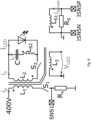
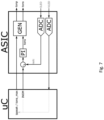
FIG. 6 shows a simplified schematic illustration of a conventional synchronous flyback converter with measurement means to measure the load current and the load voltage. The load current (e.g., an LED current ILED ) is measured by monitoring the current iC through the capacitor C, via a current transformer comprising the magnetically coupled windings L S1 and L S2 as in the phase where the primary switch S 1 is on, the LED is exclusively supplied by the capacitor C. The combination of L S1 and RS inFIG. 6 results in a frequency behavior of a high pass. - The voltage over the sensing resistor VR
S = isense ∗ RS (represented by ILED inFIG. 7 ) is connected with an internal ADC of an ASIC. This converted voltage (iadc inFIG. 7 ) is a feedback value for a controller integrated into the ASIC. The output of the controller represents the secondary on-time tons of a secondary switch (S2 inFIG. 6 ) of a flyback converter. A generator module (GEN inFIG. 7 ) in the ASIC generates the switching signals for the primary switch (S1 inFIG. 6 ) and the secondary switch (S2 inFIG. 6 ). For instance the generator module (GEN inFIG. 7 ) in the ASIC generates switching signals for the primary switch (S1 inFIG. 6 ) comprising a certain primary on-time tonp and a primary off-time toffp. The generator module (GEN inFIG. 7 ) in the ASIC may as well generate switching signals for the secondary switch (S2 inFIG. 6 ) comprising a certain secondary on-time tons and a secondary off-time toffs. Depending on the clocking of the primary switch S1 and secondary switch S2, the load current may be influenced by the controller 202. - The load voltage (which e.g. is the LED voltage) can be measured by a measurement of the voltage VLED over an additional winding L3 of the power transformer of the flyback converter. When the primary side switch S1 is closed, there will be a primary side current ip through the primary side switch S1 and the primary winding L1 of the power transformer thereby the power transformer will be magnetized. When the primary side switch S1 is being switched off and a secondary side current is flows through the secondary winding L2 as the power transformer will demagnetize. During the demagnetization phase the voltage over the secondary winding L2 will be equal to the load voltage as the secondary winding L2 is switched in parallel to the load (e.g., the LED) as long as the secondary side switch S2 is closed. As the transformer winding ratio is known the load voltage can be detected by a measurement of the voltage of the additional winding L3 (as the reflected voltage of the secondary winding L2).
- A control behaviour of the synchronous switch of a flyback converter differs from the behaviour of an synchronous buck or a boost converter. Within the synchronous flyback, a longer secondary on-time tons of the secondary switch results in a lower load current and vice versa. For example, to get a higher load current, an INOM (i.e., a reference variable or control value of a desired load current) must be increased by the user or the uC. The controller deviation (e = iadc - INOM) becomes smaller and as a result, the secondary on-time gets smaller.
- Conventional sensing circuits with a non-linear behaviour are not corrected. E.g., it is not possible to design the sensing circuit of an synchronous flyback in a way that the non-linear frequency behaviour only has a marginal influence (e.g., by shifting a corner frequency of the sensing circuit far below a lowest switching frequency of the converter).
- As no fix by hardware design is possible (like in the case of the sFLB), the sensing behaviour depends on the switching frequency fsw or to the load voltage V load:

- Where tonp is the primary on-time which depends on a bus voltage and a magnetizing inductance, which are both constant for a dedicated load current. The


- The inductance and resistor combination (L S1 and RS in
FIG. 6 ) shows a high pass behaviour with a dedicated corner frequency. If signals go below this corner frequency (e.g. at lower load voltage) the sensing signal will be damped, the voltage at the ADC will be decreased and the controller tries to decrease the secondary on-time tons to increase the sensed voltage with the effect that the load current increases as well (and deviates from a target range, that is, goes out of specification). -
FIG. 8A and FIG. 8B illustrate a load voltage dependence (i.e. an LED voltage dependence) of two separate LED currents by plotting the measured LED current (y-Axis) over different LED voltages (x-Axis). In both cases the starting point was the lowest LED voltage (15V). At this point the reference signal (INOM value) was tuned to reach the set/whished LED current. Afterwards the LED voltage of the load was increased. By increasing the LED voltage, the switching frequency increases also, and the sensing circuit damps less which leads to a higher sensed voltage. The controller tries to compensate that by increasing the secondary on-time tons which ends up in a decreasing LED current. Over the whole LED voltage range, it is not possible to stay with the current within the specified LED current range. For a low LED current (FIG. 8A ) this ends up in a secondary on-time tons where no more LED current flows, but the sensed voltage of the sensing signal still fits with the reference signal. - Besides the voltage depending sensing behaviour, there is also a dependence of the LED current. The root cause is that for each LED current another frequency behaviour over the LED voltage occurs. This is because the primary peak and so the secondary peak (c.f. Δis) depends on the set LED current.
- That is, load voltage and load current dependent sensing leads to a load current accuracy, which cannot meet a specification (i.e., an accuracy over a whole load voltage range).
- In other words, the problem with a conventional isolated converter, such as a synchronous flyback converter, is that the measurement of a load current value reacts to a change of a load voltage. This means that a correction must take into account a respective setting of the current value specification. An illustration of the problem is shown as a series of measuring points for two exemplary currents (4 mA and 400 mA) in
FIG. 8A and FIG. 8B . - In a conventional isolated converter e.g. flyback converter, the measurement of the load current takes place via a SELV barrier using coils and a shunt resistor. This is, why a measured current value reacts sensitively to a switching frequency of the secondary-side switch, in that the measurement arrangement behaves like a high-pass filter. The ASIC is thus provided with measured values that allegedly characterize the current as an input variable, to which it reacts, with the values being caused by a change in the damping behavior of the measuring circuit depending on the switching frequency and thus ultimately depending on the load. This behavior leads to the different course of the series of measured values for the two current values shown in
FIG. 8A and FIG. 8B . - Therefore, there is a need for an improved sensing circuit which overcomes this drawback using the same measurement means as for a conventional converter, e.g. shown in
FIG. 6 .. - In view of the above-mentioned problem, an objective of embodiments of the present disclosure is to improve the conventional sensing circuit.
- This or other objectives may be achieved by embodiments of the present disclosure as described in the enclosed independent claims. Advantageous implementations of embodiments of the present disclosure are further defined in the dependent claims.
- A first aspect of the present disclosure provides a sensing circuit for an isolated converter, wherein the sensing circuit is configured to obtain load current information, obtain load voltage information, determine, by a correction module of the sensing circuit, corrected load current information based on the load current information, the load voltage information and a correction formula, wherein the correction formula is configured to compensate a frequency dependent behaviour of the sensing circuit, and output the corrected load current information.
- This enables compensating the frequency behaviour of a conventional sensing circuit (e.g., within an ASIC and in real-time), which leads to a stable load current over the whole load voltage range. This also ensures that an isolated converter can be realized, which has a frequency dependent sensing circuit and fulfills a specified current accuracy over a predefined output window (e.g. from minimum load voltage to maximum load voltage). An sFLB converter can be realized which fulfils predefined standard specifications. A synchronous Flyback can be produced cheaper (based on build of material) than an LLC or LLC device of the same power range. So, it is possible to realize a cheaper LED converter for the lower power range.
- In an implementation form of the first aspect, the sensing circuit is further configured to output the corrected load current information to a controller of the isolated converter.
- This ensures that an isolated converter can be equipped and improved with the sensing circuit.
- In particular, the controller is for controlling an on-time or an off-time of one or more switches of the isolated converter.
- In another implementation form of the first aspect, the correction formula comprises a 2nd order equation for correcting the load current information.
- This ensures that the frequency behaviour of the sensing circuit can be even more improved.
- In another implementation form of the first aspect, the corrected load current information is calculated based on the following equation: iest = iadc + corr, wherein iest is the corrected load current information, iadc is the load current information, and corr is a first correction value.
- In another implementation form of the first aspect, the first correction value is calculated based on the following equation: corr = iADCideal - y, wherein iADCideal is a predefined value of the sensing circuit, and y is a second correction value.
- In another implementation form of the first aspect, the second correction value is calculated based on the following equation: y = p[0] ∗ vadc2 + p[1] ∗ vadc + p[2], wherein vadc is the load voltage information, and p[0] to p[2] are coefficients of a second order equation.
- In another implementation form of the first aspect, p[0] to p[2] are configurable by a microcontroller connected to the sensing circuit.
- In another implementation form of the first aspect, the sensing circuit is further configured to measure a load current and obtain the load current information based on the measured load current.
- In particular, the load current information is a digitally converted load current.
- In another implementation form of the first aspect, the sensing circuit is further configured to measure a load voltage and obtain the load voltage information based on the measured load voltage.
- In particular, the load voltage information is a digitally converted load voltage.
- In another implementation form of the first aspect, the load current is an LED current.
- This is beneficial, as an LED converter can be equipped with the sensing circuit.
- In another implementation form of the first aspect, the load voltage is an LED voltage.
- This is beneficial, as an LED converter can be equipped with the sensing circuit.
- In another implementation form of the first aspect, the correction formula comprises a third correction value for correcting influence of an ambient temperature on load current accuracy.
- In another implementation form of the first aspect, the sensing circuit is implemented as or as part of an ASIC.
- A second aspect of the present disclosure provides an LED converter with a sensing circuit according to the first aspect or any of its implementation forms.
- Preferably the LED converter comprises an isolated converter. In particular, the LED converter may comprise a flyback LED converter as an isolated converter. More particular, the flyback LED converter is a synchronous flyback LED converter. The isolated converter may be alternatively formed by a resonant converter, e.g. LLC converter or LCC converter.
- A third aspect of the present disclosure provides a method for operating a sensing circuit for an isolated converter, wherein the method comprises the steps of obtaining, by the sensing circuit, load current information, obtaining, by the sensing circuit, load voltage information, determining, by a correction module of the sensing circuit, corrected load current information based on the load current information, the load voltage information and a correction formula, wherein the correction formula compensates a frequency dependent behaviour of the sensing circuit, and outputting, by the sensing circuit, the corrected load current information.
- In an implementation form of the third aspect, the method further includes outputting, by the sensing circuit, the corrected load current information to a controller of the isolated converter.
- In another implementation form of the third aspect, the correction formula comprises a 2nd order equation for correcting the load current information.
- In another implementation form of the third aspect, the corrected load current information is calculated based on the following equation: iest = iadc + corr, wherein iest is the corrected load current information, iadc is the load current information, and corr is a first correction value.
- In another implementation form of the third aspect, the first correction value is calculated based on the following equation: corr = iADCideal - y, wherein iADCideal is a predefined value of the sensing circuit, and y is a second correction value.
- In another implementation form of the third aspect, the second correction value is calculated based on the following equation: y = p[0] ∗ vadc2 + p[1] ∗ vadc + p[2], wherein vadc is the load voltage information, and p[0] to p[2] are coefficients of a second order equation.
- In another implementation form of the third aspect, p [0] to p[2] are configurable by a microcontroller connected to the sensing circuit.
- In another implementation form of the third aspect, the method further includes measuring, by the sensing circuit, a load current and obtaining, by the sensing circuit, the load current information based on the measured load current.
- In another implementation form of the third aspect, the method further includes measuring, by the sensing circuit, a load voltage and obtaining, by the sensing circuit, the load voltage information based on the measured load voltage.
- In another implementation form of the third aspect, the load current is an LED current.
- In another implementation form of the third aspect, the load voltage is an LED voltage.
- In another implementation form of the third aspect, the correction formula comprises a third correction value for correcting influence of an ambient temperature on load current accuracy.
- In another implementation form of the third aspect, the sensing circuit is implemented as or as part of an integrated control circuit .
- The invention also relates to an LED converter comprising an isolated converter and designed to supply a load, e.g. a LED load, with a load current, wherein the isolated converter is controlling the load current depending on the corrected load current information.
- The third aspect and its implementation forms provide the same advantages as the first aspect and its implementation forms, respectively.
- In the following, the invention is described exemplarily with reference to the enclosed figures, in which
- FIG. 1
- shows a schematic view of a sensing circuit according to an embodiment of the present disclosure;
- FIG. 2
- shows a schematic view of a sensing circuit according to an embodiment of the present disclosure in more detail, in particular by illustrating the control principal of an sFLB;
- FIG. 3
- shows a schematic view of a LED converter comprising an isolated converter according to the invention;
- FIG. 4
- shows a schematic view of an LED current depending on an LED voltage when using the sensing circuit according to the present disclosure;
- FIG. 5
- shows a schematic view of a method according to an embodiment of the present disclosure;
- FIG. 6
- shows another schematic view of a conventional flyback converter;
- FIG. 7
- shows yet another schematic view of a conventional synchronuous flyback converter;
- FIG. 8
- shows a schematic view of an LED current depending on an LED voltage when using a conventional sensing circuit.
-
FIG. 1 shows a sensing circuit 100for anisolated converter 201, e.g. flyback converter. Thesensing circuit 100 is configured to obtain loadcurrent information 101 and to obtainload voltage information 102. Thesensing circuit 100 then determines, by acorrection module 103 of thesensing circuit 100, corrected loadcurrent information 104 based on the loadcurrent information 101, theload voltage information 102 and acorrection formula 105. Thecorrection formula 105 is configured to compensate a frequency dependent behavior of thesensing circuit 100 and output the corrected loadcurrent information 104. - In other words, the
sensing circuit 100 supplements the conventional evaluation of current and voltage in that the measured value of the load current is corrected by an estimator (i.e. correction module 103). - Characterizing values for a load current and a load voltage can be supplied to the
correction module 103, e.g., in a digital or analog manner. The load voltage for example can be detected by an auxiliary winding on a primary side of a converter (which is not shown in the figure). The correction can be implemented in that a correction value is added to the actually recorded value of the load current, with the correction value being determined using an equation. This correction value is then added to the measured current value. Thereby, the corrected loadcurrent information 104 is calculated. - The
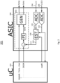
sensing circuit 100 is now going to be described in more detail in view ofFIG. 2 . Thesensing circuit 100 ofFIG. 2 includes all functions and features of thesensing circuit 100 as described in view ofFIG. 1 . - As it is further illustrated in
FIG. 2 , the corrected loadcurrent information 104 can be output to a controller 202 of anisolated converter 201. The converter 201 (e.g. a flyback converter 201) then can be controlled based on the corrected loadcurrent information 104. Preferably the controller 202 controls the on-time of a secondary switch of a synchronous flyback. - Further optionally, the
correction formula 105 can comprise a 2nd order equation for correcting the loadcurrent information 101. That is, the correction value can be determined using an equation of a second order. In other words, the correction value is determined non-linearly, respectively as a quadratic equation depending on the measured voltage. - The corrected load
current information 104, that is, the feedback signal for the controller (labelled "iest" inFIG. 2 ), is provided by the correction module 103 (labelled "EST.", i.e. an estimator) and can compensate the frequency behaviour in particular based on the following equations:
Optionally, the corrected loadcurrent information 104 can be calculated based on the following equation:
- In this equation, iest is the corrected load
current information 104, iadc is the loadcurrent information 101, and corr is a first correction value. That is, iadc is the digital converted LED current (ILED inFIG. 2 ) - Further optionally, the first correction value can be calculated based on the following equation:

- In this equation, iADCideal is a predefined value of the sensing circuit, and y is a second correction value. iADCideal in particular can be a value preset by a microcontroller uC.
- Further optionally, the second correction value can be calculated based on the following equation:

- In this equation, vadc is the
load voltage information 102, and p[0] to p[2] are coefficients of a second order equation. In particular, since the second correction value shows a second order behaviour, also thesensing circuit 100 shows a second order behaviour. In particular, vadc is the digitally converted voltage of VLED inFIG. 2 . - In particular, p[0] to p[2] are configurable by a
microcontroller 203 connected to thesensing circuit 100, for example depending on the set LED current and/or INOM. - For example for one LED converter / wattage and for a 4 mA LED current, these values can be: p[0]=-1.12e - 6; p[1]=74.63e - 3; p[2]= 1728.71
- For example for one LED converter / wattage and for a 400 mA LED current, these values can be: p[0]=-5.6e - 6; p[1]=315.4e - 3; p[2]= 30151.35
- In other words, the coefficient values p[0] to p[2] can be determined in the
microcontroller uC 203 and fed to the correction module 103 (e.g., integrated in an integrated control circuit such as an ASIC) to determine the correction value there using the respectively required coefficients. - Further optionally, the
sensing circuit 100 can measure a load current 204 and obtain the loadcurrent information 101 based on the measured load current 204. That is, the loadcurrent information 101 is the digitally converted load current 204. - Further optionally, the
sensing circuit 100 can measure aload voltage 205 and obtain theload voltage information 102 based on the measuredload voltage 205. That is, the measuredload voltage information 102 is the digitally convertedload voltage 205. - Further optionally, the load current 204 is an LED current. Further optionally, the
load voltage 205 is an LED voltage. - The
correction formula 105 may also comprises a third correction value for correcting influence of an ambient temperature on load current accuracy. - In particular, the
sensing circuit 100 can be implemented as or as part of anintegrated control circuit 206, e.g. anASIC 206. An integrated control circuit, such as an ASIC, can be used to carry out the operations performed by the correction module, if other controllers would be too slow for performing said operations. In principle, however, any integrated circuit that allows the measured value to be corrected sufficiently quick can be used. This is beneficial as a too slow correction would lead to a visible change in the emitted light, since jumps in the output currents occur because the converter only reacts to corrections that are carried out slowly and in stages. -
FIG. 3 shows an LED converter according to the invention comprising anisolated converter 201, which is formed by a DC/DC-converter. Theisolated converter 201 may be formed for instance by a synchronous flyback as shown inFIG. 6 including measurement means for the load current and the load voltage. Theisolated converter 201 may be supplied with a DC voltage provided by a power factor correction circuit (PFC) 210, which forms an AC/DC-converter. Theisolated converter 201 supplies theLED 212 with a load current. Theisolated converter 201 is controlled by anintegrated control circuit 206 which may also control the operation of the power factor correction circuit (PFC) 210. The sensing circuit 100 (not shown here) may be integrated into theintegrated control circuit 206. The operation of the LED converter may be controlled via a dimming interface such as a DALI interface via theinterface circuit 211. Theinterface circuit 211 may receive digital dimming commands and may forward the received digital dimming commands to themicrocontroller 203 and / or theintegrated control circuit 206. For instance, the received digital dimming commands may define reference signals such as INOM (the nominal load current, or the LED current). Themicrocontroller 203 may define or influence control parameters of theintegrated control circuit 206 in order to influence the operation and control of theintegrated control circuit 206 and thus the load current. - The LED converter may comprise an
isolated converter 206 and is designed to supply a load, e.g. a LED load, with a load current, wherein theisolated converter 201 is controlling the load current 204 depending on the corrected loadcurrent information 104 outputted by thesensing circuit 100. - FIG. 4A and FIG. 4B comparing the current values for 4 mA and 400 mA (401a, 401b) show upper and lower limit values for the LED current (dotted lines), which define a target corridor and which can be achieved with the non-linear correction. It should be noted that the
sensing circuit 100 is not limited to be used in an sFLB. Basically, thesensing circuit 100 can improve any type of SELV barrier control gear, with a frequency dependency on the secondary side leading to a falsification of the measurement result. -
FIG. 5 shows amethod 500 for operating asensing circuit 100 for anisolated converter 201. Themethod 500 comprises a first step of obtaining 501, by thesensing circuit 100, loadcurrent information 101, and a second step of obtaining 502, by thesensing circuit 100,load voltage information 102. The method further comprises a third step of determining 503, by acorrection module 103 of thesensing circuit 100, corrected loadcurrent information 104 based on the loadcurrent information 101, theload voltage information 102 and acorrection formula 105, wherein thecorrection formula 105 compensates a frequency dependent behaviour of thesensing circuit 100. Themethod 500 comprises a last step of outputting 504, by thesensing circuit 100, the corrected loadcurrent information 104.
Claims (15)
- A sensing circuit (100) for an isolated converter (201), e.g. a flyback or a resonant isolated converter, wherein the sensing circuit (100) is configured to:- obtain load current information (101),- obtain load voltage information (102),- determine, by a correction module (103) of the sensing circuit (100), corrected load current information (104) based on the load current information (101), the load voltage information (102) and a correction formula (105), wherein the correction formula (105) is configured to compensate a frequency dependent behaviour of the sensing circuit (100), and- output the corrected load current information (104).
- The sensing circuit (100) according to claim 1, further configured to output the corrected load current information (104) to a controller (202) of the isolated converter (201).
- The sensing circuit (100) according to claim 1 or 2, wherein the correction formula (105) comprises a 2nd order equation for correcting the load current information (101).
- The sensing circuit (100) according to any one of the preceding claims, wherein the corrected load current information (104) is calculated based on the following equation:

- The sensing circuit (100) according to claim 4, wherein the first correction value is calculated based on the following equation:

- The sensing circuit (100) according to claim 5, wherein the second correction value is calculated based on the following equation:

- The sensing circuit (100) according to claim 6, wherein p[0] to p[2] are configurable by a microcontroller (203) connected to the sensing circuit (100).
- The sensing circuit (100) according to any one of the preceding claims, further configured to measure a load current (204) and obtain the load current information (101) based on the measured load current (204).
- The sensing circuit (100) according to any one of the preceding claims, further configured to measure a load voltage (205) and obtain the load voltage information (102) based on the measured load voltage (205).
- The sensing circuit (100) according to any one of the preceding claims, wherein the load current (204) is an LED current and/or, wherein the load voltage (205) is an LED voltage.
- The sensing circuit (100) according to any one of the preceding claims, wherein the correction formula (105) comprises a third correction value for correcting influence of an ambient temperature on load current accuracy.
- The sensing circuit (100) according to any one of the preceding claims, wherein the sensing circuit (100) is implemented as or as part of an integrated control circuit (206).
- An LED converter with a sensing circuit (100) according to any one of claims 1 to 12.
- The LED converter according to claim 13, further comprising an isolated converter (206) and designed to supply a load, e.g. an LED load, with a load current, wherein the isolated converter (201) is controlling the load current (204) depending on the corrected load current information (104).
- A Method (500) for operating a sensing circuit (100) for an isolated converter (201), wherein the method (500) comprises the steps of:- obtaining (501), by the sensing circuit (100), load current information (101),- obtaining (502), by the sensing circuit (100), load voltage information (102),- determining (503), by a correction module (103) of the sensing circuit (100), corrected load current information (104) based on the load current information (101), the load voltage information (102) and a correction formula (105), wherein the correction formula (105) compensates a frequency dependent behaviour of the sensing circuit (100), and- outputting (504), by the sensing circuit (100), the corrected load current information (104).
Priority Applications (2)
| Application Number | Priority Date | Filing Date | Title |
|---|---|---|---|
| EP22183483.1A EP4304066A1 (en) | 2022-07-07 | 2022-07-07 | A sensing circuit for an isolated converter |
| PCT/EP2023/066950 WO2024008464A1 (en) | 2022-07-07 | 2023-06-22 | A sensing circuit for an isolated converter |
Applications Claiming Priority (1)
| Application Number | Priority Date | Filing Date | Title |
|---|---|---|---|
| EP22183483.1A EP4304066A1 (en) | 2022-07-07 | 2022-07-07 | A sensing circuit for an isolated converter |
Publications (1)
| Publication Number | Publication Date |
|---|---|
| EP4304066A1 true EP4304066A1 (en) | 2024-01-10 |
Family
ID=82399269
Family Applications (1)
| Application Number | Title | Priority Date | Filing Date |
|---|---|---|---|
| EP22183483.1A Pending EP4304066A1 (en) | 2022-07-07 | 2022-07-07 | A sensing circuit for an isolated converter |
Country Status (2)
| Country | Link |
|---|---|
| EP (1) | EP4304066A1 (en) |
| WO (1) | WO2024008464A1 (en) |
Citations (5)
| Publication number | Priority date | Publication date | Assignee | Title |
|---|---|---|---|---|
| US20110103112A1 (en) * | 2009-10-30 | 2011-05-05 | Delta Electronics, Inc. | Current sensing signal comparing device, and current sensing signal comparing method |
| US20180287495A1 (en) * | 2014-08-27 | 2018-10-04 | Renesas Electronics America Inc. | Current sensing with rdson correction |
| US20190195922A1 (en) * | 2017-12-21 | 2019-06-27 | Schneider Electric USA, Inc. | Current sensor error compensation method |
| US20210018573A1 (en) * | 2019-07-15 | 2021-01-21 | Allegro Microsystems, Llc | Methods and Apparatus For Frequency Effect Compensation In Magnetic Field Current Sensors |
| EP3890445A1 (en) * | 2020-03-31 | 2021-10-06 | Tridonic GmbH & Co. KG | Primary side switched converter for providing a voltage supply to an led load |
-
2022
- 2022-07-07 EP EP22183483.1A patent/EP4304066A1/en active Pending
-
2023
- 2023-06-22 WO PCT/EP2023/066950 patent/WO2024008464A1/en not_active Ceased
Patent Citations (5)
| Publication number | Priority date | Publication date | Assignee | Title |
|---|---|---|---|---|
| US20110103112A1 (en) * | 2009-10-30 | 2011-05-05 | Delta Electronics, Inc. | Current sensing signal comparing device, and current sensing signal comparing method |
| US20180287495A1 (en) * | 2014-08-27 | 2018-10-04 | Renesas Electronics America Inc. | Current sensing with rdson correction |
| US20190195922A1 (en) * | 2017-12-21 | 2019-06-27 | Schneider Electric USA, Inc. | Current sensor error compensation method |
| US20210018573A1 (en) * | 2019-07-15 | 2021-01-21 | Allegro Microsystems, Llc | Methods and Apparatus For Frequency Effect Compensation In Magnetic Field Current Sensors |
| EP3890445A1 (en) * | 2020-03-31 | 2021-10-06 | Tridonic GmbH & Co. KG | Primary side switched converter for providing a voltage supply to an led load |
Also Published As
| Publication number | Publication date |
|---|---|
| WO2024008464A1 (en) | 2024-01-11 |
Similar Documents
| Publication | Publication Date | Title |
|---|---|---|
| EP2437909B1 (en) | Welding power supply for and method of determining during welding a weld cable inductance | |
| US7817447B2 (en) | Accurate voltage regulation of a primary-side regulation power supply in continuous conduction mode operation | |
| CA2764309C (en) | Welding power supply with digital control of duty cycle | |
| US7492058B2 (en) | Modular uninterruptible power supply with loadsharing between modules | |
| US8780587B2 (en) | Switching regulator and control circuit and control method thereof | |
| US8587967B2 (en) | System and method for indirect control of a converter output | |
| WO2010002547A1 (en) | Led driver with multiple feedback loops | |
| US20170079095A1 (en) | Primary Side Controlled LED Driver with Ripple Cancellation | |
| US20120268971A1 (en) | Power supply for controlling current | |
| US7372216B2 (en) | Constant brightness control for electro-luminescent lamp | |
| JP2000156975A (en) | Dc-to-dc converter | |
| TW201347599A (en) | Light source driving circuit, controller and method for controlling power converter | |
| JP2003244953A (en) | Dc-dc converter | |
| EP4012912B1 (en) | Control circuit for power conversion device | |
| WO2024008464A1 (en) | A sensing circuit for an isolated converter | |
| KR101215074B1 (en) | Power supply for controlling current | |
| CN114189131A (en) | Control method and control circuit of switching power supply and switching power supply | |
| US20150042303A1 (en) | Control circuit of power converter and method therefore | |
| EP1324476B1 (en) | Converter with inductor and digital controlled timing | |
| US11864292B2 (en) | Isolated converter with improved current sensing | |
| US9380670B2 (en) | Generating a voltage feedback signal in non-isolated LED drivers |
Legal Events
| Date | Code | Title | Description |
|---|---|---|---|
| PUAI | Public reference made under article 153(3) epc to a published international application that has entered the european phase |
Free format text: ORIGINAL CODE: 0009012 |
|
| STAA | Information on the status of an ep patent application or granted ep patent |
Free format text: STATUS: THE APPLICATION HAS BEEN PUBLISHED |
|
| AK | Designated contracting states |
Kind code of ref document: A1 Designated state(s): AL AT BE BG CH CY CZ DE DK EE ES FI FR GB GR HR HU IE IS IT LI LT LU LV MC MK MT NL NO PL PT RO RS SE SI SK SM TR |
|
| STAA | Information on the status of an ep patent application or granted ep patent |
Free format text: STATUS: REQUEST FOR EXAMINATION WAS MADE |
|
| 17P | Request for examination filed |
Effective date: 20240301 |
|
| RBV | Designated contracting states (corrected) |
Designated state(s): AL AT BE BG CH CY CZ DE DK EE ES FI FR GB GR HR HU IE IS IT LI LT LU LV MC MK MT NL NO PL PT RO RS SE SI SK SM TR |
|
| STAA | Information on the status of an ep patent application or granted ep patent |
Free format text: STATUS: EXAMINATION IS IN PROGRESS |
|
| 17Q | First examination report despatched |
Effective date: 20260414 |