EP4304034A1 - Method for controlling stray currents in a marine electrical supply system and a marine vessel comprising a marine electrical supply system - Google Patents
Method for controlling stray currents in a marine electrical supply system and a marine vessel comprising a marine electrical supply system Download PDFInfo
- Publication number
- EP4304034A1 EP4304034A1 EP22183159.7A EP22183159A EP4304034A1 EP 4304034 A1 EP4304034 A1 EP 4304034A1 EP 22183159 A EP22183159 A EP 22183159A EP 4304034 A1 EP4304034 A1 EP 4304034A1
- Authority
- EP
- European Patent Office
- Prior art keywords
- current
- stray
- vessel
- supply system
- electrical supply
- Prior art date
- Legal status (The legal status is an assumption and is not a legal conclusion. Google has not performed a legal analysis and makes no representation as to the accuracy of the status listed.)
- Pending
Links
Images



Classifications
-
- H—ELECTRICITY
- H02—GENERATION; CONVERSION OR DISTRIBUTION OF ELECTRIC POWER
- H02J—ELECTRIC POWER NETWORKS; CIRCUIT ARRANGEMENTS OR SYSTEMS FOR SUPPLYING OR DISTRIBUTING ELECTRIC POWER; SYSTEMS FOR STORING ELECTRIC ENERGY
- H02J3/00—Circuit arrangements for AC mains or AC distribution networks
- H02J3/001—Arrangements for handling faults or abnormalities, e.g. emergencies or contingencies
- H02J3/0012—Arrangements for handling faults or abnormalities, e.g. emergencies or contingencies characterised by the contingency detection means in AC networks, e.g. using phasor measurement units [PMU], synchrophasors or contingency analysis
-
- C—CHEMISTRY; METALLURGY
- C23—COATING METALLIC MATERIAL; COATING MATERIAL WITH METALLIC MATERIAL; CHEMICAL SURFACE TREATMENT; DIFFUSION TREATMENT OF METALLIC MATERIAL; COATING BY VACUUM EVAPORATION, BY SPUTTERING, BY ION IMPLANTATION OR BY CHEMICAL VAPOUR DEPOSITION, IN GENERAL; INHIBITING CORROSION OF METALLIC MATERIAL OR INCRUSTATION IN GENERAL
- C23F—NON-MECHANICAL REMOVAL OF METALLIC MATERIAL FROM SURFACE; INHIBITING CORROSION OF METALLIC MATERIAL OR INCRUSTATION IN GENERAL; MULTI-STEP PROCESSES FOR SURFACE TREATMENT OF METALLIC MATERIAL INVOLVING AT LEAST ONE PROCESS PROVIDED FOR IN CLASS C23 AND AT LEAST ONE PROCESS COVERED BY SUBCLASS C21D OR C22F OR CLASS C25
- C23F13/00—Inhibiting corrosion of metals by anodic or cathodic protection
- C23F13/02—Inhibiting corrosion of metals by anodic or cathodic protection cathodic; Selection of conditions, parameters or procedures for cathodic protection, e.g. of electrical conditions
- C23F13/04—Controlling or regulating desired parameters
-
- B—PERFORMING OPERATIONS; TRANSPORTING
- B63—SHIPS OR OTHER WATERBORNE VESSELS; RELATED EQUIPMENT
- B63B—SHIPS OR OTHER WATERBORNE VESSELS; EQUIPMENT FOR SHIPPING
- B63B79/00—Monitoring properties or operating parameters of vessels in operation
- B63B79/10—Monitoring properties or operating parameters of vessels in operation using sensors, e.g. pressure sensors, strain gauges or accelerometers
-
- B—PERFORMING OPERATIONS; TRANSPORTING
- B63—SHIPS OR OTHER WATERBORNE VESSELS; RELATED EQUIPMENT
- B63B—SHIPS OR OTHER WATERBORNE VESSELS; EQUIPMENT FOR SHIPPING
- B63B79/00—Monitoring properties or operating parameters of vessels in operation
- B63B79/40—Monitoring properties or operating parameters of vessels in operation for controlling the operation of vessels, e.g. monitoring their speed, routing or maintenance schedules
-
- G—PHYSICS
- G01—MEASURING; TESTING
- G01R—MEASURING ELECTRIC VARIABLES; MEASURING MAGNETIC VARIABLES
- G01R31/00—Arrangements for testing electric properties; Arrangements for locating electric faults; Arrangements for electrical testing characterised by what is being tested not provided for elsewhere
- G01R31/50—Testing of electric apparatus, lines, cables or components for short-circuits, continuity, leakage current or incorrect line connections
- G01R31/52—Testing for short-circuits, leakage current or ground faults
-
- H—ELECTRICITY
- H02—GENERATION; CONVERSION OR DISTRIBUTION OF ELECTRIC POWER
- H02H—EMERGENCY PROTECTIVE CIRCUIT ARRANGEMENTS
- H02H3/00—Emergency protective circuit arrangements for automatic disconnection directly responsive to an undesired change from normal electric working condition with or without subsequent reconnection ; integrated protection
- H02H3/16—Emergency protective circuit arrangements for automatic disconnection directly responsive to an undesired change from normal electric working condition with or without subsequent reconnection ; integrated protection responsive to fault current to earth, frame or mass
-
- H—ELECTRICITY
- H02—GENERATION; CONVERSION OR DISTRIBUTION OF ELECTRIC POWER
- H02H—EMERGENCY PROTECTIVE CIRCUIT ARRANGEMENTS
- H02H9/00—Emergency protective circuit arrangements for limiting excess current or voltage without disconnection
- H02H9/02—Emergency protective circuit arrangements for limiting excess current or voltage without disconnection responsive to excess current
-
- H—ELECTRICITY
- H02—GENERATION; CONVERSION OR DISTRIBUTION OF ELECTRIC POWER
- H02H—EMERGENCY PROTECTIVE CIRCUIT ARRANGEMENTS
- H02H9/00—Emergency protective circuit arrangements for limiting excess current or voltage without disconnection
- H02H9/08—Limitation or suppression of earth fault currents, e.g. Petersen coil
-
- B—PERFORMING OPERATIONS; TRANSPORTING
- B63—SHIPS OR OTHER WATERBORNE VESSELS; RELATED EQUIPMENT
- B63J—AUXILIARIES ON VESSELS
- B63J3/00—Driving of auxiliaries
- B63J3/04—Driving of auxiliaries from power plant other than propulsion power plant
- B63J2003/043—Driving of auxiliaries from power plant other than propulsion power plant using shore connectors for electric power supply from shore-borne mains, or other electric energy sources external to the vessel, e.g. for docked, or moored vessels
-
- C—CHEMISTRY; METALLURGY
- C23—COATING METALLIC MATERIAL; COATING MATERIAL WITH METALLIC MATERIAL; CHEMICAL SURFACE TREATMENT; DIFFUSION TREATMENT OF METALLIC MATERIAL; COATING BY VACUUM EVAPORATION, BY SPUTTERING, BY ION IMPLANTATION OR BY CHEMICAL VAPOUR DEPOSITION, IN GENERAL; INHIBITING CORROSION OF METALLIC MATERIAL OR INCRUSTATION IN GENERAL
- C23F—NON-MECHANICAL REMOVAL OF METALLIC MATERIAL FROM SURFACE; INHIBITING CORROSION OF METALLIC MATERIAL OR INCRUSTATION IN GENERAL; MULTI-STEP PROCESSES FOR SURFACE TREATMENT OF METALLIC MATERIAL INVOLVING AT LEAST ONE PROCESS PROVIDED FOR IN CLASS C23 AND AT LEAST ONE PROCESS COVERED BY SUBCLASS C21D OR C22F OR CLASS C25
- C23F2213/00—Aspects of inhibiting corrosion of metals by anodic or cathodic protection
- C23F2213/10—Controlling or regulating parameters
- C23F2213/11—Controlling or regulating parameters for structures subject to stray currents
-
- C—CHEMISTRY; METALLURGY
- C23—COATING METALLIC MATERIAL; COATING MATERIAL WITH METALLIC MATERIAL; CHEMICAL SURFACE TREATMENT; DIFFUSION TREATMENT OF METALLIC MATERIAL; COATING BY VACUUM EVAPORATION, BY SPUTTERING, BY ION IMPLANTATION OR BY CHEMICAL VAPOUR DEPOSITION, IN GENERAL; INHIBITING CORROSION OF METALLIC MATERIAL OR INCRUSTATION IN GENERAL
- C23F—NON-MECHANICAL REMOVAL OF METALLIC MATERIAL FROM SURFACE; INHIBITING CORROSION OF METALLIC MATERIAL OR INCRUSTATION IN GENERAL; MULTI-STEP PROCESSES FOR SURFACE TREATMENT OF METALLIC MATERIAL INVOLVING AT LEAST ONE PROCESS PROVIDED FOR IN CLASS C23 AND AT LEAST ONE PROCESS COVERED BY SUBCLASS C21D OR C22F OR CLASS C25
- C23F2213/00—Aspects of inhibiting corrosion of metals by anodic or cathodic protection
- C23F2213/30—Anodic or cathodic protection specially adapted for a specific object
- C23F2213/31—Immersed structures, e.g. submarine structures
-
- H—ELECTRICITY
- H02—GENERATION; CONVERSION OR DISTRIBUTION OF ELECTRIC POWER
- H02J—ELECTRIC POWER NETWORKS; CIRCUIT ARRANGEMENTS OR SYSTEMS FOR SUPPLYING OR DISTRIBUTING ELECTRIC POWER; SYSTEMS FOR STORING ELECTRIC ENERGY
- H02J2105/00—Networks for supplying or distributing electric power characterised by their spatial reach or by the load
- H02J2105/30—Networks for supplying or distributing electric power characterised by their spatial reach or by the load the load networks being external to vehicles, i.e. exchanging power with vehicles
- H02J2105/31—Networks for supplying or distributing electric power characterised by their spatial reach or by the load the load networks being external to vehicles, i.e. exchanging power with vehicles for ships or vessels
-
- H—ELECTRICITY
- H02—GENERATION; CONVERSION OR DISTRIBUTION OF ELECTRIC POWER
- H02J—ELECTRIC POWER NETWORKS; CIRCUIT ARRANGEMENTS OR SYSTEMS FOR SUPPLYING OR DISTRIBUTING ELECTRIC POWER; SYSTEMS FOR STORING ELECTRIC ENERGY
- H02J4/00—Circuit arrangements for mains or distribution networks not specified as AC or DC; Circuit arrangements for mains or distribution networks combining AC and DC sections or sub-networks
Definitions
- the electrical devices can include one or more battery chargers, depending on the number and type of batteries, bilge pumps, air-condition units, lights and other auxiliary devices requiring electrical power.
- DC galvanic corrosion which arises when a metal hull or other metallic components and a dissimilar metal, for instance the propellers, are both placed in the same aqueous solution, particularly in seawater.
- corrosion protection can comprise impressed current corrosion protection (ICCP) systems and/or passive sacrificial anodes.
- AC and DC shore power or vessel systems can have different causes.
- the AC power source at the marina may not be properly wired and may have power, neutral, and safety ground lines interchanged (commonly called reversed polarity).
- the AC system onboard the vessel is not properly wired, or has AC leakage to the vessel ground.
- the DC systems provided to overcome the galvanic action provided on the vessel are frequently interconnected with the safety ground. Leakage currents through this path can result in accelerated corrosion. AC voltage on the safety ground represents a serious electrolysis and safety problem for all vessels and marina apparatus.
- This stray current causes all underwater corrosion protective active elements (typically zinc's) and the more noble underwater metallic parts (e.g. bronze propellers) of the vessel with a DC ground connected to the AC safety ground wiring to be electrically connected.
- the result is a very large area electrolytic corrosion network, which may rapidly deplete the more active elements on the vessel. The can be made worse by the combined effect of galvanic corrosion if multiple vessels are connected to the same shore facility.
- Another form of damage is electrolytic corrosion caused by introducing shore AC electrical power commonly connected into the DC ground systems of vessels. This corrosion arises due to improper wiring, leakage, and AC return line voltage drop that is inducing low levels of AC voltage into the common AC shore power safety ground. This can result in depletion of both the active elements, and the more noble underwater elements of a vessel. This type of damage attacks all through-hull fittings, corroding and eventually destroying them, so that the vessel can be subjected to flooding due to failure of the through-hull fittings.
- a further failure mechanism is electrical damage that develops as a result of stray current unbalance in shore electric power delivered to the vessel. This happens when current is being supplied to the vessel, but not returning through the intended return line. The unbalanced current can be leaking off through the water into the marina, or through the AC safety ground.
- This type of failure in an otherwise properly wired vessel may be caused by movement of electrical contacts touching each other in an electrical distribution panel, or by ingress of seawater into a circuit that is intended to be insulated, but which circuit instead leaks off to ground through the wet area.
- Some electrical systems, like refrigerators, heaters, air-conditioners, or timer run devices may have faults that do not activate until switched on unexpectedly, long after the operators have departed the vessel.
- the invention provides an improved method for controlling stray currents in a marine electrical supply system aiming to solve the above-mentioned problems.
- An object of the invention is to provide a method for controlling stray currents in a marine electrical supply system, a marine electrical supply system comprising a protective earth circuit operable using this method and a vessel comprising such a marine electrical supply system.
- the object is achieved by a method for controlling stray currents, a marine electrical supply system comprising a protective earth circuit operable using the method and a marine vessel comprising such a protective earth circuit according to the appended claims.
- the marine electrical supply system can comprise a shore based source of direct current (DC) electrical power or a source of alternating current (AC) electrical power connectable to a vessel or a floating marine structure.
- DC direct current
- AC alternating current
- the vessel or floating structure can be provided with an AC/DC rectifier.
- the invention is primarily described for application to a marine vessel, although it is applicable to both marine vessels and floating marine structures with an electrical supply system provided with a protective earth circuit, also termed a PE circuit.
- the invention relates to a method for cancelling stray currents in a marine electrical supply system, which system comprises a protective earth (PE) circuit connecting a vessel to ground when a source of power is connected to the vessel.
- PE protective earth
- the stray-current in the protective earth circuit can be counteracted if the stray current detected by the current sensor is above a threshold value.
- the threshold value can be set to zero for continuous control. Alternatively it can be set to a few milliamperes (mA) so that the supply system does not initiate control in response to minimal random variations in stray current.
- the current monitoring is performed using a suitable current sensor such as an inductive current sensor arranged in the PE circuit.
- a suitable current sensor such as an inductive current sensor arranged in the PE circuit.
- the inductive current sensor is a current transformer.
- the inductive current sensor is a Hall Effect sensor.
- the inductive current sensor is a fluxgate sensor.
- the method involves counteracting the stray-current in the protective earth circuit in order to reduce the stray current to zero, or at least to a value below the threshold value.
- a detected stray current in the protective earth circuit is counteracted by inducing a counter-current into the protective earth circuit using a suitable means such as protected earth line PE.
- the invention relates to a marine electrical supply system to connect a marine vessel to a source of shore power, wherein the electrical supply system has a protective earth circuit (PE).
- the PE circuit comprises a first positive earth connection extending from the shore power source to a vessel connector, a second positive earth connection extending from the vessel connector to a ground bus bar, and a third positive earth connection extending from the ground bus bar to one or more vessel loads.
- the second positive earth connection comprises a current sensor arranged to detect a stray-current in the protective earth circuit (PE) and to emit a signal proportional to the detected current, a control unit arranged to receive the emitted signal and to generate and transmit a control signal, and a means for counteracting the stray-current in the protective earth circuit in response to the transmitted control signal, whereby the means is operated to reduce the stray current to a value at or near zero current.
- PE protective earth circuit
- the means for counteracting the stray-current in the protective earth circuit is arranged to be operated if the detected stray current is above a threshold value.
- the threshold value can be set to zero for continuous control. Alternatively it can be set to a few milliamperes (mA) so that the supply system does not initiate control in response to minimal random variations in stray current.
- the current monitoring is performed using a suitable current sensor such as an inductive current sensor arranged in the PE circuit.
- a suitable current sensor such as an inductive current sensor arranged in the PE circuit.
- the inductive current sensor is a current transformer.
- the inductive current sensor is a Hall Effect sensor.
- the inductive current sensor is a fluxgate sensor.
- the means for counteracting the stray-current in the protective earth circuit is operated to reduce the stray current to zero, or at least to a value below the threshold value.
- a detected stray current in the protective earth circuit is counteracted by inducing a counter-current into the protective earth circuit using a suitable means such as a controllable induction coil.
- the invention relates to a marine vessel or floating structure comprising a marine electrical supply system as described in any one of the above examples.
- the method and system according to the invention provides a means for counteracting stray-current in the protective earth circuit to reduce the stray current. This solves the problem of damage from electrolytic corrosion caused by introducing shore AC electrical power commonly connected into the DC ground systems of vessels. A further problem solved by the invention is the risk of electrical damage that develops as a result of stray current unbalance in shore electric power delivered to the vessel. It is also possible to avoid the combined effect of galvanic corrosion if multiple marine vessels are connected to the same shore facility.
- FIG. 1 shows a schematically illustrated vessel 100 connected to DC shore power 102.
- the figure shows a marine electrical supply system, which system comprises a grounded line 115 connecting the vessel 100 to ground 114 when the source of power 102 is connected to the vessel 100.
- the supply system comprises said source of power 102 which is connected to a vessel connector 104.
- the electrical supply system of the vessel is releasably connected to the source of power 102 by means of vessel connector 104, which can be a standard plug-and-socket arrangement.
- the source of power 102 is schematically indicated as a single power line (see Fig.3 ) from the grid or a shore energy storage facility.
- the vessel connector 104 is connected to one or more vessel loads, indicated as a general vessel load 106, via a power line 105.
- the vessel load 106 is in turn grounded to the vessel hull at a point 107 and/or to ground 108 on-board the vessel.
- the electrical supply system is further connected to on-shore ground 114 via a grounded line 115 which is connected to the vessel connector 104.
- An Insulation Monitoring Device (IMD) 103 is connected between the source of power 102 and the grounded line 115.
- the IMD 103 is arranged for measuring the insulation resistance of the power supply system and monitors it against earth.
- a first grounded line 116 connects the vessel connector 104 to a device 110 for controlling stray current, which in turn is connected to a vessel busbar 109 via a connecting grounded line.
- a busbar also "bus bar” is a metallic strip or bar, typically housed inside switchgear, panel boards and busway enclosures for local high current power distribution.
- the vessel busbar 109 is connected to the vessel load 106 via a second grounded line 117 and is grounded to the vessel hull at a point 111.
- the vessel hull is conductively connected to on-shore ground via the surrounding seawater acting as an electrolyte and forming a return connection.
- the resistivity of the seawater is schematically indicated by a first resistor 112.
- the resistivity of the ground between the electrolyte and the on-shore ground 114 for the electrical supply 102 is schematically indicated by a second resistor 113.
- PE protected earth
- device 110 for controlling stray current is arranged to monitor the current in the protective earth circuit 101 using a current sensor and to determine if a stray current is detected by the current sensor. If a stray current is detected the device 110 is arranged to counteract the stray-current in the protective earth circuit 101 to reduce the stray current to a value at or near zero current. This operation will be described in further detail in connection with Figure 3 below.
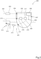
- FIG. 2 shows a schematically illustrated vessel 200 connected to AC shore power 202.
- the figure shows a marine electrical supply system, which system comprises a grounded line 215 connecting the vessel 200 to ground 214 when the source of power 202 is connected to the vessel 200.
- the supply system comprises said source of power 202 which is connected to a vessel connector 204.
- the electrical supply system of the vessel is releasably connected to the source of power 202 by means of vessel connector 204, which can be a standard plug-and-socket arrangement.
- the source of power 202 is schematically indicated as a single power line (see Fig.4 ) from the grid or a portable AC energy supply facility.
- the vessel connector 204 is connected to one or more vessel loads, indicated as a general vessel load 206, via a power line 205.
- the vessel load 206 is in turn grounded to the vessel hull at a point 207 and/or to ground 208 on-board the vessel.
- the electrical supply system is further connected to the vessel connector 204 via a Residual-Current Device (RCD) 203.
- the RCD 203 is an electrical safety device that quickly breaks an electrical circuit with leakage current to ground.
- a first grounded line 216 connects the vessel connector 204 to a device 210 for controlling stray current, which in turn is connected to a vessel busbar 209 via a connecting grounded line.
- the vessel busbar 209 is connected to the vessel load 206 via a second grounded line 217 and is grounded to the vessel hull at a point 211.
- the vessel hull is conductively connected to on-shore ground via the surrounding seawater acting as an electrolyte and forming a return connection.
- the resistivity of the seawater is schematically indicated by a first resistor 212.
- the resistivity of the ground between the electrolyte and the on-shore ground 214 for the electrical supply 202 is schematically indicated by a second resistor 213.
- This arrangement creates a protected earth (PE) circuit comprising
- device 210 for controlling stray current is arranged to monitor the current in the protective earth circuit 201 using a current sensor and to determine if a stray current is detected by the current sensor. If a stray current is detected the device 210 is arranged to counteract the stray-current in the protective earth circuit 201 to reduce the stray current to a value at or near zero current. This operation will be described in further detail in connection with Figure 4 below.
- FIG 3 shows a schematic vessel electrical system 301 connected to a source of DC shore power 302.
- the vessel is releasably connected to the shore power 302 via a vessel connector 304.
- the shore power 302 also comprises a connection to ground (not shown; see Fig.1 ; "114").
- the vessel connector 304 is connected to a general vessel load 306 via a power line 305 comprising a positive DC+ conductor and a negative DC- conductor.
- the vessel connector 304 is further connected to a vessel busbar 309 via a protected earth line PE which passes through a device 310 for controlling stray current in the protected earth line PE.
- the vessel busbar 309 is in turn connected to the vessel load 306 and to ground 308.
- connection to ground 308 connects the busbar to the vessel hull.
- a protective earth circuit (see Fig.1 ; "101") is created, which runs from on-shore ground, through a grounded line in the vessel connector 304, through the busbar 309 and back through the vessel hull and the surrounding seawater.
- the device 310 for controlling stray current in the protected earth line PE is connected between the vessel connector 304 and the busbar 309.
- the device 310 comprises an inductive current sensor 311 which in this case is a current transformer inductively connected to the protected earth line PE and having a sensor for measuring current.
- the current sensor 311 transmits a signal representing the magnitude of the stray current in the protected earth line PE to a current monitor 312.
- the current monitor 312 transmits the signal to a control circuit 313, which outputs a control signal to a current inductor 314.
- the control circuit 313 can compare the input signal from the current monitor 312 with a threshold value.
- the control signal is regulated depending on the magnitude and direction of the detected stray current.
- the control signal is received by a current inductor 314 which is arranged to output a current to a controllable induction coil 315 in response to the control signal.
- a current inductor 314 which is arranged to output a current to a controllable induction coil 315 in response to the control signal.
- the induction coil 315 induces a counter-current into the protected earth line PE the stray current detected by the current sensor 311 is reduced.
- the device 310 is arranged to counteract stray-current detected in the protective earth circuit in order to reduce the stray current to a value at or near zero current.
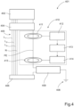
- FIG 4 shows a schematic vessel electrical system 401 connected to AC shore power 402.
- the vessel is releasably connected to the shore power 402 via a vessel connector 404.
- the shore power 402 also comprises a connection to ground (not shown; see Fig.2 ; "214").
- the vessel connector 404 is connected to a general vessel load 406 via a power line 405 comprising a first, second and third conductor L 1 , L 2 , L 3 and a neutral conductor N.
- the vessel connector 404 is further connected to a vessel busbar 409 via a protected earth line PE which passes through a device 410 for controlling stray current in the protected earth line PE.
- the vessel busbar 409 is in turn connected to the vessel load 406 and to ground 408.
- connection to ground 408 connects the busbar to the vessel hull.
- a protective earth circuit (see Fig.2 ; "201") is created, which runs from on-shore ground, through a grounded line in the vessel connector 404, through the busbar 409 and back through the vessel hull and the surrounding seawater.
- the device 410 for controlling stray current in the protected earth line PE is connected between the vessel connector 404 and the busbar 409.
- the device 410 comprises an inductive current sensor 411 which in this case is a current transformer inductively connected to the protected earth line PE and having a sensor for measuring current.
- the current sensor 411 transmits a signal representing the magnitude of the stray current in the protected earth line PE to a current monitor 412.
- the current monitor 412 transmits the signal to a control circuit 413, which outputs a control signal to a current inductor 414.
- the control circuit 413 can compare the input signal from the current monitor 412 with a threshold value.
- the control signal is regulated depending on the magnitude and direction of the detected stray current.
- the control signal is received by a current inductor 414 which is arranged to output a current to a controllable induction coil 415 in response to the control signal.
- a current inductor 414 which is arranged to output a current to a controllable induction coil 415 in response to the control signal.
- the induction coil 415 induces a counter-current into the protected earth line PE the stray current detected by the current sensor 411 is reduced.
- the device 410 is arranged to counteract stray-current detected in the protective earth circuit in order to reduce the stray current to a value at or near zero current.
- FIG. 5 shows a schematically arrangement for counteracting stray currents.
- the arrangement comprises a device 500 for controlling stray current in a protected earth line PE which is connected between a vessel connector (see Fig.3 , "304"; Fig.4 , "404") and a busbar (see Fig.3 , "404"; Fig.4 , “409”).
- the device 500 comprises an inductive current sensor which in this case is an inductive current transformer 511 inductively connected to the protected earth line PE and having a sensor 512 for measuring current.
- the current sensor 512 transmits an input signal representing the magnitude of the stray current in the protected earth line PE to a current monitoring control unit 513, which outputs a control signal to a current inductor 514 that control a current inductive coil 516 in a current transformer 515.
- the control unit 513 can compare the magnitude of the input signal from the current sensor 512 with a threshold value. When the threshold is exceeded then the control signal is regulated depending on the magnitude and direction of the detected stray current. If a threshold is not used, then the control signal is regulated immediately depending on the magnitude and direction of the detected stray current.
- the control signal from the control unit 513 is received by a current inductor 514 which is arranged to output a current to the controllable induction coil 516 in the current transformer 515 in response to the control signal.
- a current inductor 514 which is arranged to output a current to the controllable induction coil 516 in the current transformer 515 in response to the control signal.
- the induction coil 516 induces a counter-current into the protected earth line PE the stray current detected by the current sensor 512 is reduced.
- the device 500 is arranged to counteract stray-current detected in the protective earth circuit in order to reduce the stray current to a value at or near zero current.
Landscapes
- Engineering & Computer Science (AREA)
- Chemical & Material Sciences (AREA)
- Mechanical Engineering (AREA)
- Power Engineering (AREA)
- Combustion & Propulsion (AREA)
- Ocean & Marine Engineering (AREA)
- Physics & Mathematics (AREA)
- General Physics & Mathematics (AREA)
- Materials Engineering (AREA)
- Metallurgy (AREA)
- Organic Chemistry (AREA)
- Emergency Protection Circuit Devices (AREA)
Abstract
Description
- The present invention relates to a method for controlling stray currents in a marine electrical supply system in order to prevent degradation of both metallic components and sacrificial elements on-board a vessel connected to a source of shore power supplying either alternating current (AC) or direct current (DC). When connected to shore power, stray currents from outside source can flows through wiring, vessel, surrounding water to ground, which stray currents contribute to severe electrolytic corrosion, or externally induced galvanic action on the vessel.
- It is normal practice to provide shore power for vessels at shore facilities such as marinas, which power sources commonly comprise either a DC system or a 3-/4-wire AC system for various electrical devices onboard the vessel. The electrical devices can include one or more battery chargers, depending on the number and type of batteries, bilge pumps, air-condition units, lights and other auxiliary devices requiring electrical power.
- It is also common practice to provide protection for the hull, conductive fittings, paint, and other conductors in and on the vessel against corrosion, commonly called DC galvanic corrosion, which arises when a metal hull or other metallic components and a dissimilar metal, for instance the propellers, are both placed in the same aqueous solution, particularly in seawater. Examples of corrosion protection can comprise impressed current corrosion protection (ICCP) systems and/or passive sacrificial anodes.
- The occurrence of stray currents in AC and DC shore power or vessel systems can have different causes. For instance, the AC power source at the marina may not be properly wired and may have power, neutral, and safety ground lines interchanged (commonly called reversed polarity). Alternatively, the AC system onboard the vessel is not properly wired, or has AC leakage to the vessel ground. These problems can cause leakage or fault AC currents and cause serious harm or failure to underwater parts and electrical devices onboard the vessel.
- The DC systems provided to overcome the galvanic action provided on the vessel are frequently interconnected with the safety ground. Leakage currents through this path can result in accelerated corrosion. AC voltage on the safety ground represents a serious electrolysis and safety problem for all vessels and marina apparatus.
- This stray current causes all underwater corrosion protective active elements (typically zinc's) and the more noble underwater metallic parts (e.g. bronze propellers) of the vessel with a DC ground connected to the AC safety ground wiring to be electrically connected. The result is a very large area electrolytic corrosion network, which may rapidly deplete the more active elements on the vessel. The can be made worse by the combined effect of galvanic corrosion if multiple vessels are connected to the same shore facility.
- Another form of damage is electrolytic corrosion caused by introducing shore AC electrical power commonly connected into the DC ground systems of vessels. This corrosion arises due to improper wiring, leakage, and AC return line voltage drop that is inducing low levels of AC voltage into the common AC shore power safety ground. This can result in depletion of both the active elements, and the more noble underwater elements of a vessel. This type of damage attacks all through-hull fittings, corroding and eventually destroying them, so that the vessel can be subjected to flooding due to failure of the through-hull fittings.
- A further failure mechanism is electrical damage that develops as a result of stray current unbalance in shore electric power delivered to the vessel. This happens when current is being supplied to the vessel, but not returning through the intended return line. The unbalanced current can be leaking off through the water into the marina, or through the AC safety ground. This type of failure in an otherwise properly wired vessel may be caused by movement of electrical contacts touching each other in an electrical distribution panel, or by ingress of seawater into a circuit that is intended to be insulated, but which circuit instead leaks off to ground through the wet area. Some electrical systems, like refrigerators, heaters, air-conditioners, or timer run devices may have faults that do not activate until switched on unexpectedly, long after the operators have departed the vessel.
- The invention provides an improved method for controlling stray currents in a marine electrical supply system aiming to solve the above-mentioned problems.
- An object of the invention is to provide a method for controlling stray currents in a marine electrical supply system, a marine electrical supply system comprising a protective earth circuit operable using this method and a vessel comprising such a marine electrical supply system.
- The object is achieved by a method for controlling stray currents, a marine electrical supply system comprising a protective earth circuit operable using the method and a marine vessel comprising such a protective earth circuit according to the appended claims.
- In the subsequent text, the marine electrical supply system can comprise a shore based source of direct current (DC) electrical power or a source of alternating current (AC) electrical power connectable to a vessel or a floating marine structure. In the case of a source of AC power the vessel or floating structure can be provided with an AC/DC rectifier. The invention is primarily described for application to a marine vessel, although it is applicable to both marine vessels and floating marine structures with an electrical supply system provided with a protective earth circuit, also termed a PE circuit.
- According to one aspect of the invention, the invention relates to a method for cancelling stray currents in a marine electrical supply system, which system comprises a protective earth (PE) circuit connecting a vessel to ground when a source of power is connected to the vessel. The method involves the steps of:
- monitoring the current in the protective earth circuit using a current sensor;
- determining if a stray current is detected by the current sensor, and
if a stray current is detected - counteracting the stray-current in the protective earth circuit to reduce the stray current to a value at or near zero current.
- The stray-current in the protective earth circuit can be counteracted if the stray current detected by the current sensor is above a threshold value. The threshold value can be set to zero for continuous control. Alternatively it can be set to a few milliamperes (mA) so that the supply system does not initiate control in response to minimal random variations in stray current.
- The current monitoring is performed using a suitable current sensor such as an inductive current sensor arranged in the PE circuit. According to a first example, the inductive current sensor is a current transformer. According to a second example, the inductive current sensor is a Hall Effect sensor. According to a third example, the inductive current sensor is a fluxgate sensor.
- The method involves counteracting the stray-current in the protective earth circuit in order to reduce the stray current to zero, or at least to a value below the threshold value. A detected stray current in the protective earth circuit is counteracted by inducing a counter-current into the protective earth circuit using a suitable means such as protected earth line PE.
- According to a second aspect of the invention, the invention relates to a marine electrical supply system to connect a marine vessel to a source of shore power, wherein the electrical supply system has a protective earth circuit (PE). The PE circuit comprises a first positive earth connection extending from the shore power source to a vessel connector, a second positive earth connection extending from the vessel connector to a ground bus bar, and a third positive earth connection extending from the ground bus bar to one or more vessel loads.
- The second positive earth connection comprises a current sensor arranged to detect a stray-current in the protective earth circuit (PE) and to emit a signal proportional to the detected current, a control unit arranged to receive the emitted signal and to generate and transmit a control signal, and a means for counteracting the stray-current in the protective earth circuit in response to the transmitted control signal, whereby the means is operated to reduce the stray current to a value at or near zero current.
- The means for counteracting the stray-current in the protective earth circuit is arranged to be operated if the detected stray current is above a threshold value. The threshold value can be set to zero for continuous control. Alternatively it can be set to a few milliamperes (mA) so that the supply system does not initiate control in response to minimal random variations in stray current.
- The current monitoring is performed using a suitable current sensor such as an inductive current sensor arranged in the PE circuit. According to a first example, the inductive current sensor is a current transformer. According to a second example, the inductive current sensor is a Hall Effect sensor. According to a third example, the inductive current sensor is a fluxgate sensor.
- The means for counteracting the stray-current in the protective earth circuit is operated to reduce the stray current to zero, or at least to a value below the threshold value. A detected stray current in the protective earth circuit is counteracted by inducing a counter-current into the protective earth circuit using a suitable means such as a controllable induction coil.
- According to a third aspect of the invention, the invention relates to a marine vessel or floating structure comprising a marine electrical supply system as described in any one of the above examples.
- The method and system according to the invention provides a means for counteracting stray-current in the protective earth circuit to reduce the stray current. This solves the problem of damage from electrolytic corrosion caused by introducing shore AC electrical power commonly connected into the DC ground systems of vessels. A further problem solved by the invention is the risk of electrical damage that develops as a result of stray current unbalance in shore electric power delivered to the vessel. It is also possible to avoid the combined effect of galvanic corrosion if multiple marine vessels are connected to the same shore facility.
- Further advantages and advantageous features of the invention are disclosed in the following description and in the dependent claims.
- With reference to the appended drawings, below follows a more detailed description of embodiments of the invention cited as examples. In the drawings:
- Fig. 1
- shows a schematically illustrated vessel connected to DC shore power;
- Fig. 2
- shows a schematically illustrated vessel connected to AC shore power;
- Fig. 3
- shows a schematic vessel electrical system connected to DC shore power;
- Fig. 4
- shows a schematic vessel electrical system connected to AC shore power; and
- Fig. 5
- shows a schematically arrangement for counteracting stray currents.
-
Figure 1 shows a schematically illustratedvessel 100 connected to DC shorepower 102. The figure shows a marine electrical supply system, which system comprises a groundedline 115 connecting thevessel 100 toground 114 when the source ofpower 102 is connected to thevessel 100. The supply system comprises said source ofpower 102 which is connected to avessel connector 104. The electrical supply system of the vessel is releasably connected to the source ofpower 102 by means ofvessel connector 104, which can be a standard plug-and-socket arrangement. The source ofpower 102 is schematically indicated as a single power line (seeFig.3 ) from the grid or a shore energy storage facility. Thevessel connector 104 is connected to one or more vessel loads, indicated as ageneral vessel load 106, via apower line 105. Thevessel load 106 is in turn grounded to the vessel hull at apoint 107 and/or to ground 108 on-board the vessel. - The electrical supply system is further connected to on-
shore ground 114 via a groundedline 115 which is connected to thevessel connector 104. An Insulation Monitoring Device (IMD) 103 is connected between the source ofpower 102 and the groundedline 115. TheIMD 103 is arranged for measuring the insulation resistance of the power supply system and monitors it against earth. On-board thevessel 100, a first groundedline 116 connects thevessel connector 104 to adevice 110 for controlling stray current, which in turn is connected to avessel busbar 109 via a connecting grounded line. In the field of electric power distribution, a busbar (also "bus bar") is a metallic strip or bar, typically housed inside switchgear, panel boards and busway enclosures for local high current power distribution. They can also be used to connect high voltage equipment at electrical switchyards, and low voltage equipment in battery banks. Thevessel busbar 109 is connected to thevessel load 106 via a second groundedline 117 and is grounded to the vessel hull at apoint 111. The vessel hull is conductively connected to on-shore ground via the surrounding seawater acting as an electrolyte and forming a return connection. The resistivity of the seawater is schematically indicated by afirst resistor 112. Similarly, the resistivity of the ground between the electrolyte and the on-shore ground 114 for theelectrical supply 102 is schematically indicated by asecond resistor 113. This arrangement creates a protected earth (PE)circuit 101 comprising - the on-
shore ground 114, - the grounded
line 115 connected to thevessel connector 104, - the first grounded
line 116 connecting thevessel connector 104 and thedevice 110 for controlling stray current, - the
vessel busbar 109 connected between thedevice 110 for controlling stray current and the hullground connection point 111; and - the return connection through the seawater back to the on-shore ground.
- In operation,
device 110 for controlling stray current is arranged to monitor the current in theprotective earth circuit 101 using a current sensor and to determine if a stray current is detected by the current sensor. If a stray current is detected thedevice 110 is arranged to counteract the stray-current in theprotective earth circuit 101 to reduce the stray current to a value at or near zero current. This operation will be described in further detail in connection withFigure 3 below. -
Figure 2 shows a schematically illustratedvessel 200 connected toAC shore power 202. The figure shows a marine electrical supply system, which system comprises a groundedline 215 connecting thevessel 200 toground 214 when the source ofpower 202 is connected to thevessel 200. The supply system comprises said source ofpower 202 which is connected to avessel connector 204. The electrical supply system of the vessel is releasably connected to the source ofpower 202 by means ofvessel connector 204, which can be a standard plug-and-socket arrangement. The source ofpower 202 is schematically indicated as a single power line (seeFig.4 ) from the grid or a portable AC energy supply facility. Thevessel connector 204 is connected to one or more vessel loads, indicated as ageneral vessel load 206, via apower line 205. Thevessel load 206 is in turn grounded to the vessel hull at apoint 207 and/or to ground 208 on-board the vessel. - The electrical supply system is further connected to the
vessel connector 204 via a Residual-Current Device (RCD) 203. TheRCD 203 is an electrical safety device that quickly breaks an electrical circuit with leakage current to ground. On-board thevessel 200, a first groundedline 216 connects thevessel connector 204 to adevice 210 for controlling stray current, which in turn is connected to avessel busbar 209 via a connecting grounded line. Thevessel busbar 209 is connected to thevessel load 206 via a second groundedline 217 and is grounded to the vessel hull at apoint 211. The vessel hull is conductively connected to on-shore ground via the surrounding seawater acting as an electrolyte and forming a return connection. The resistivity of the seawater is schematically indicated by afirst resistor 212. Similarly, the resistivity of the ground between the electrolyte and the on-shore ground 214 for theelectrical supply 202 is schematically indicated by asecond resistor 213. This arrangement creates a protected earth (PE) circuit comprising - the on-
shore ground 214, - the grounded
line 215 connected to thevessel connector 204, - the first grounded
line 216 connecting thevessel connector 204 and thedevice 210 for controlling stray current, - the
vessel busbar 209 connected between thedevice 210 for controlling stray current and the hullground connection point 211; and - the return connection through the seawater back to the on-shore ground.
- In operation,
device 210 for controlling stray current is arranged to monitor the current in theprotective earth circuit 201 using a current sensor and to determine if a stray current is detected by the current sensor. If a stray current is detected thedevice 210 is arranged to counteract the stray-current in theprotective earth circuit 201 to reduce the stray current to a value at or near zero current. This operation will be described in further detail in connection withFigure 4 below. -
Figure 3 shows a schematic vesselelectrical system 301 connected to a source ofDC shore power 302. The vessel is releasably connected to theshore power 302 via avessel connector 304. Theshore power 302 also comprises a connection to ground (not shown; seeFig.1 ; "114"). On-board the vessel, thevessel connector 304 is connected to ageneral vessel load 306 via apower line 305 comprising a positive DC+ conductor and a negative DC- conductor. Thevessel connector 304 is further connected to avessel busbar 309 via a protected earth line PE which passes through adevice 310 for controlling stray current in the protected earth line PE. Thevessel busbar 309 is in turn connected to thevessel load 306 and toground 308. The connection toground 308 connects the busbar to the vessel hull. As theshore power 302 and thevessel busbar 309 are both connected to ground, a protective earth circuit (seeFig.1 ; "101") is created, which runs from on-shore ground, through a grounded line in thevessel connector 304, through thebusbar 309 and back through the vessel hull and the surrounding seawater. - As described above, the
device 310 for controlling stray current in the protected earth line PE is connected between thevessel connector 304 and thebusbar 309. Thedevice 310 comprises an inductivecurrent sensor 311 which in this case is a current transformer inductively connected to the protected earth line PE and having a sensor for measuring current. Thecurrent sensor 311 transmits a signal representing the magnitude of the stray current in the protected earth line PE to acurrent monitor 312. Thecurrent monitor 312 transmits the signal to acontrol circuit 313, which outputs a control signal to acurrent inductor 314. Thecontrol circuit 313 can compare the input signal from thecurrent monitor 312 with a threshold value. The control signal is regulated depending on the magnitude and direction of the detected stray current. The control signal is received by acurrent inductor 314 which is arranged to output a current to acontrollable induction coil 315 in response to the control signal. As theinduction coil 315 induces a counter-current into the protected earth line PE the stray current detected by thecurrent sensor 311 is reduced. In this way thedevice 310 is arranged to counteract stray-current detected in the protective earth circuit in order to reduce the stray current to a value at or near zero current. -
Figure 4 shows a schematic vesselelectrical system 401 connected toAC shore power 402. The vessel is releasably connected to theshore power 402 via avessel connector 404. Theshore power 402 also comprises a connection to ground (not shown; seeFig.2 ; "214"). On-board the vessel, thevessel connector 404 is connected to ageneral vessel load 406 via apower line 405 comprising a first, second and third conductor L1, L2, L3 and a neutral conductor N. Thevessel connector 404 is further connected to avessel busbar 409 via a protected earth line PE which passes through adevice 410 for controlling stray current in the protected earth line PE. Thevessel busbar 409 is in turn connected to thevessel load 406 and toground 408. The connection toground 408 connects the busbar to the vessel hull. As theshore power 402 and thevessel busbar 409 are both connected to ground, a protective earth circuit (seeFig.2 ; "201") is created, which runs from on-shore ground, through a grounded line in thevessel connector 404, through thebusbar 409 and back through the vessel hull and the surrounding seawater. - As described above, the
device 410 for controlling stray current in the protected earth line PE is connected between thevessel connector 404 and thebusbar 409. Thedevice 410 comprises an inductivecurrent sensor 411 which in this case is a current transformer inductively connected to the protected earth line PE and having a sensor for measuring current. Thecurrent sensor 411 transmits a signal representing the magnitude of the stray current in the protected earth line PE to acurrent monitor 412. Thecurrent monitor 412 transmits the signal to acontrol circuit 413, which outputs a control signal to acurrent inductor 414. Thecontrol circuit 413 can compare the input signal from thecurrent monitor 412 with a threshold value. The control signal is regulated depending on the magnitude and direction of the detected stray current. The control signal is received by acurrent inductor 414 which is arranged to output a current to acontrollable induction coil 415 in response to the control signal. As theinduction coil 415 induces a counter-current into the protected earth line PE the stray current detected by thecurrent sensor 411 is reduced. In this way thedevice 410 is arranged to counteract stray-current detected in the protective earth circuit in order to reduce the stray current to a value at or near zero current. -
Figure 5 shows a schematically arrangement for counteracting stray currents. The arrangement comprises adevice 500 for controlling stray current in a protected earth line PE which is connected between a vessel connector (seeFig.3 , "304";Fig.4 , "404") and a busbar (seeFig.3 , "404";Fig.4 , "409"). Thedevice 500 comprises an inductive current sensor which in this case is an inductivecurrent transformer 511 inductively connected to the protected earth line PE and having asensor 512 for measuring current. Thecurrent sensor 512 transmits an input signal representing the magnitude of the stray current in the protected earth line PE to a currentmonitoring control unit 513, which outputs a control signal to acurrent inductor 514 that control a currentinductive coil 516 in acurrent transformer 515. Thecontrol unit 513 can compare the magnitude of the input signal from thecurrent sensor 512 with a threshold value. When the threshold is exceeded then the control signal is regulated depending on the magnitude and direction of the detected stray current. If a threshold is not used, then the control signal is regulated immediately depending on the magnitude and direction of the detected stray current. The control signal from thecontrol unit 513 is received by acurrent inductor 514 which is arranged to output a current to thecontrollable induction coil 516 in thecurrent transformer 515 in response to the control signal. As theinduction coil 516 induces a counter-current into the protected earth line PE the stray current detected by thecurrent sensor 512 is reduced. In this way thedevice 500 is arranged to counteract stray-current detected in the protective earth circuit in order to reduce the stray current to a value at or near zero current. - It is to be understood that the present invention is not limited to the embodiments described above and illustrated in the drawings; rather, the skilled person will recognize that many changes and modifications may be made within the scope of the appended claims.
Claims (13)
- Method for cancelling stray currents in a marine electrical supply system, which system comprises a protective earth circuit (101; 201) connecting a vessel (100; 200) to ground when a source of power (102; 202) is connected to the vessel, wherein the method involves the steps of:- monitoring the current in the protective earth circuit using a current sensor (311; 411; 512);- determining if a stray current is detected by the current sensor, and if a stray current is detected,- counteracting the stray-current in the protective earth circuit to reduce the stray current to a value at or near zero current.
- Method according to claim 1, wherein the stray-current in the protective earth circuit (101; 201) is counteracted if the detected stray current is above a threshold value.
- Method according to claim 2, wherein the stray-current in the protective earth circuit (101; 201) is counteracted to reduce the stray current to a value below the threshold value.
- Method according to any one of claims 1-3, wherein the current monitoring is performed using an inductive current sensor.
- Method according to claim 4, wherein the inductive current sensor is a current transformer, a Hall Effect sensor or a fluxgate sensor.
- Method according to any one of claims 1-5, wherein the stray-current is counteracted by inducing a counter-current using a controllable induction coil (315; 415; 515).
- Marine electrical supply system to connect a marine vessel (100; 200) to a source of shore power (102; 202), wherein the electrical supply system has a protective earth circuit (101; 201) comprising- a first positive earth connection (115; 215) extending from the shore power source (102; 202) to a vessel connector (104; 204);- a second positive earth connection (116; 216) extending from the vessel connector (104; 204) to a ground bus bar (109; 209); and- a third positive earth connection (117; 217) extending from the ground bus bar (109; 209) to one or more vessel loads (106; 206);wherein the second positive earth connection comprises- a current sensor (311; 411; 512) arranged to detect a stray-current in the protective earth circuit (PE) and to emit a signal proportional to the detected current;- a control unit (313; 413; 513) arranged to receive the emitted signal and to generate and transmit a control signal; and- a means (315; 415; 515) for counteracting the stray-current in the protective earth circuit in response to the transmitted control signal, whereby the means is operated to reduce the stray current to a value at or near zero current.
- Method according to claim 7, wherein the means for counteracting the stray-current in the protective earth circuit is operated if the detected stray current is above a threshold value.
- Method according to claim 8, wherein the means for counteracting the stray-current in the protective earth circuit is operated to reduce the stray current to a value below the threshold value.
- Marine electrical supply system according to any one of claims 7-9, wherein the current sensor is an inductive current sensor.
- Marine electrical supply system according to claim 10, wherein the inductive current sensor is a current transformer, a Hall Effect sensor or a fluxgate sensor.
- Marine electrical supply system according to any one of claims 7-11, wherein the means (315; 415; 515) for counteracting stray-current is a controllable induction coil.
- Vessel comprising a marine electrical supply system according to claim 7.
Priority Applications (3)
| Application Number | Priority Date | Filing Date | Title |
|---|---|---|---|
| EP22183159.7A EP4304034A1 (en) | 2022-07-05 | 2022-07-05 | Method for controlling stray currents in a marine electrical supply system and a marine vessel comprising a marine electrical supply system |
| CN202310770681.9A CN117353261A (en) | 2022-07-05 | 2023-06-28 | Method for controlling stray currents in marine power supply systems and marine vessels including marine power supply systems |
| US18/342,883 US12381389B2 (en) | 2022-07-05 | 2023-06-28 | Method for controlling stray currents in a marine electrical supply system and a marine vessel comprising a marine electrical supply system |
Applications Claiming Priority (1)
| Application Number | Priority Date | Filing Date | Title |
|---|---|---|---|
| EP22183159.7A EP4304034A1 (en) | 2022-07-05 | 2022-07-05 | Method for controlling stray currents in a marine electrical supply system and a marine vessel comprising a marine electrical supply system |
Publications (1)
| Publication Number | Publication Date |
|---|---|
| EP4304034A1 true EP4304034A1 (en) | 2024-01-10 |
Family
ID=82557929
Family Applications (1)
| Application Number | Title | Priority Date | Filing Date |
|---|---|---|---|
| EP22183159.7A Pending EP4304034A1 (en) | 2022-07-05 | 2022-07-05 | Method for controlling stray currents in a marine electrical supply system and a marine vessel comprising a marine electrical supply system |
Country Status (3)
| Country | Link |
|---|---|
| US (1) | US12381389B2 (en) |
| EP (1) | EP4304034A1 (en) |
| CN (1) | CN117353261A (en) |
Cited By (1)
| Publication number | Priority date | Publication date | Assignee | Title |
|---|---|---|---|---|
| EP4749863A1 (en) * | 2024-11-18 | 2026-05-27 | Bender GmbH & Co. KG | Methods and devices for minimizing a dc protective conductor current which is subject to corrosion |
Families Citing this family (1)
| Publication number | Priority date | Publication date | Assignee | Title |
|---|---|---|---|---|
| CN119627945B (en) * | 2024-12-11 | 2025-12-30 | 大连中远海运重工有限公司 | Novel Voltage Drop Design Method for Integrated Power Distribution Networks |
Citations (2)
| Publication number | Priority date | Publication date | Assignee | Title |
|---|---|---|---|---|
| US20090160427A1 (en) * | 2007-12-21 | 2009-06-25 | Drake William R | Shore power cord ground wire current detector |
| US20200036180A1 (en) * | 2018-07-27 | 2020-01-30 | Dr. Ing. H.C. F. Porsche Aktiengesellschaft | Method and device for reducing leakage currents |
Family Cites Families (1)
| Publication number | Priority date | Publication date | Assignee | Title |
|---|---|---|---|---|
| FR2977086B1 (en) * | 2011-06-22 | 2013-06-14 | Renault Sa | SYSTEM AND METHOD FOR COMPENSATING AN ON-BOARD BATTERY CHARGER IN A VEHICLE |
-
2022
- 2022-07-05 EP EP22183159.7A patent/EP4304034A1/en active Pending
-
2023
- 2023-06-28 CN CN202310770681.9A patent/CN117353261A/en active Pending
- 2023-06-28 US US18/342,883 patent/US12381389B2/en active Active
Patent Citations (2)
| Publication number | Priority date | Publication date | Assignee | Title |
|---|---|---|---|---|
| US20090160427A1 (en) * | 2007-12-21 | 2009-06-25 | Drake William R | Shore power cord ground wire current detector |
| US20200036180A1 (en) * | 2018-07-27 | 2020-01-30 | Dr. Ing. H.C. F. Porsche Aktiengesellschaft | Method and device for reducing leakage currents |
Cited By (1)
| Publication number | Priority date | Publication date | Assignee | Title |
|---|---|---|---|---|
| EP4749863A1 (en) * | 2024-11-18 | 2026-05-27 | Bender GmbH & Co. KG | Methods and devices for minimizing a dc protective conductor current which is subject to corrosion |
Also Published As
| Publication number | Publication date |
|---|---|
| CN117353261A (en) | 2024-01-05 |
| US20240014650A1 (en) | 2024-01-11 |
| US12381389B2 (en) | 2025-08-05 |
Similar Documents
| Publication | Publication Date | Title |
|---|---|---|
| US12381389B2 (en) | Method for controlling stray currents in a marine electrical supply system and a marine vessel comprising a marine electrical supply system | |
| EP2442417B1 (en) | A protection system for electrical power distribution system using directional current detection and logic within protective relays | |
| Paul et al. | Designing cold ironing power systems: Electrical safety during ship berthing | |
| US7994795B2 (en) | Shore power cord ground wire current detector | |
| US3636409A (en) | Electrical ground filter means for boats supplied with a shore-based source of alternating current power | |
| US20240326628A1 (en) | Method for charging a battery in an electric marine vessel | |
| CN109672142B (en) | Equipotential protection technology for low-voltage shore power system of ship | |
| US20110178649A1 (en) | Method for preventing electric shock by contact with connected-to-ground electric appliances and installations, and apparatus therefor | |
| Parise et al. | High voltage shore connections (HVSC), an IEC/ISO/IEEE 80005-1 compliant solution: The neutral grounding system | |
| Paul et al. | Cold ironing-power system grounding and safety analysis | |
| CN207956004U (en) | One kind being used for remote-controlled vehicle power distribution unit | |
| KR102350330B1 (en) | Balancing Transformer for minimizing leakage current | |
| Nelson et al. | The grounding of marine power systems: Problems and solutions | |
| Mehammer et al. | Grounding Strategies for High Voltage Shore Connection of Large Passenger Vessels | |
| CN109956014A (en) | A power distribution unit for remotely operated submersibles | |
| Nowak | Selected issues conerning the atypical TT/TN-S networks usage in marine electricity systems | |
| EP2072393A1 (en) | Electrical system for floating installation, in particular offshore vessel, with a feeding comprising a combined transformer for resistance grounding and transformer pre-magnetization | |
| Paul et al. | Cold ironing power system design and electrical safety | |
| Parise et al. | A novel approach to the electrical safety of low‐voltage installations: the TN‐Island grounding system | |
| Parise et al. | The TN-island system for cold ironing | |
| Wenta et al. | Design and programming of a walking robot | |
| KR101521818B1 (en) | Power supply device for DPS | |
| JPH10142282A (en) | Leakage alarm device for ships | |
| Paul et al. | System capacitance and its effects on cold ironing power system grounding | |
| Paul et al. | Low-voltage shore connection power systems |
Legal Events
| Date | Code | Title | Description |
|---|---|---|---|
| PUAI | Public reference made under article 153(3) epc to a published international application that has entered the european phase |
Free format text: ORIGINAL CODE: 0009012 |
|
| STAA | Information on the status of an ep patent application or granted ep patent |
Free format text: STATUS: THE APPLICATION HAS BEEN PUBLISHED |
|
| AK | Designated contracting states |
Kind code of ref document: A1 Designated state(s): AL AT BE BG CH CY CZ DE DK EE ES FI FR GB GR HR HU IE IS IT LI LT LU LV MC MK MT NL NO PL PT RO RS SE SI SK SM TR |
|
| STAA | Information on the status of an ep patent application or granted ep patent |
Free format text: STATUS: REQUEST FOR EXAMINATION WAS MADE |
|
| 17P | Request for examination filed |
Effective date: 20240613 |
|
| RBV | Designated contracting states (corrected) |
Designated state(s): AL AT BE BG CH CY CZ DE DK EE ES FI FR GB GR HR HU IE IS IT LI LT LU LV MC MK MT NL NO PL PT RO RS SE SI SK SM TR |