EP4304020A1 - Panel-mounted connector - Google Patents
Panel-mounted connector Download PDFInfo
- Publication number
- EP4304020A1 EP4304020A1 EP22762970.6A EP22762970A EP4304020A1 EP 4304020 A1 EP4304020 A1 EP 4304020A1 EP 22762970 A EP22762970 A EP 22762970A EP 4304020 A1 EP4304020 A1 EP 4304020A1
- Authority
- EP
- European Patent Office
- Prior art keywords
- panel
- connector
- receptacle
- inner receptacle
- lock
- Prior art date
- Legal status (The legal status is an assumption and is not a legal conclusion. Google has not performed a legal analysis and makes no representation as to the accuracy of the status listed.)
- Pending
Links
- 230000002093 peripheral effect Effects 0.000 claims abstract description 47
- 238000006073 displacement reaction Methods 0.000 claims description 47
- 238000001514 detection method Methods 0.000 description 15
- 238000007789 sealing Methods 0.000 description 7
- 230000035515 penetration Effects 0.000 description 4
- 229920003002 synthetic resin Polymers 0.000 description 4
- 239000000057 synthetic resin Substances 0.000 description 4
- 230000000694 effects Effects 0.000 description 2
- 230000002452 interceptive effect Effects 0.000 description 2
- 230000008878 coupling Effects 0.000 description 1
- 238000010168 coupling process Methods 0.000 description 1
- 238000005859 coupling reaction Methods 0.000 description 1
- 230000000717 retained effect Effects 0.000 description 1
- 238000000926 separation method Methods 0.000 description 1
Images






Classifications
-
- H—ELECTRICITY
- H01—ELECTRIC ELEMENTS
- H01R—ELECTRICALLY-CONDUCTIVE CONNECTIONS; STRUCTURAL ASSOCIATIONS OF A PLURALITY OF MUTUALLY-INSULATED ELECTRICAL CONNECTING ELEMENTS; COUPLING DEVICES; CURRENT COLLECTORS
- H01R13/00—Details of coupling devices of the kinds covered by groups H01R12/70 or H01R24/00 - H01R33/00
- H01R13/73—Means for mounting coupling parts to apparatus or structures, e.g. to a wall
- H01R13/74—Means for mounting coupling parts in openings of a panel
- H01R13/741—Means for mounting coupling parts in openings of a panel using snap fastening means
- H01R13/743—Means for mounting coupling parts in openings of a panel using snap fastening means integral with the housing
-
- H—ELECTRICITY
- H01—ELECTRIC ELEMENTS
- H01R—ELECTRICALLY-CONDUCTIVE CONNECTIONS; STRUCTURAL ASSOCIATIONS OF A PLURALITY OF MUTUALLY-INSULATED ELECTRICAL CONNECTING ELEMENTS; COUPLING DEVICES; CURRENT COLLECTORS
- H01R13/00—Details of coupling devices of the kinds covered by groups H01R12/70 or H01R24/00 - H01R33/00
- H01R13/62—Means for facilitating engagement or disengagement of coupling parts or for holding them in engagement
- H01R13/629—Additional means for facilitating engagement or disengagement of coupling parts, e.g. aligning or guiding means, levers, gas pressure electrical locking indicators, manufacturing tolerances
- H01R13/62977—Pivoting levers actuating linearly camming means
Definitions
- the present disclosure relates to a panel mount connector.
- a connector for example, described in Japanese Unexamined Patent Publication No. 2003-187911 (patent literature 1 below) is known as a panel mount connector to be mounted on a panel such as a body or door of an automotive vehicle.
- a male housing is mounted through a mounting hole open and formed in the panel from a back side of the panel and a female housing is connected to that male housing from a front side of the panel.
- the male housing includes a receptacle in the form of a tube projecting forward from a terminal accommodating portion.
- a flange capable of contacting the back surface of the panel as the male housing is mounted on the housing is provided to protrude on the outer peripheral surface of the receptacle at a position somewhat behind a front end.
- a part of the receptacle projecting further forward than the flange serves as a penetration portion to be fit and passed through the mounting hole and project on the front side of the panel at the time of mounting on the panel.
- a fixing locking portion and a resilient locking portion are provided to face the flange at the front end of the penetration portion. If the male housing is mounted on the panel, the fixing locking portion and the resilient locking portion can be locked to the front surface of the panel after passing through the mounting hole and sandwich the panel between these and the flange.
- Patent Literature 1 Japanese Unexamined Patent Publication No. 2003-187911
- the penetration portion may be deformed, the locking of the fixing locking portion and the resilient locking portion with the panel may be released and the male housing may be detached from the panel if the receptacle receives a strong force.
- the present disclosure is directed to a panel mount connector to be mounted on a panel including a connector mounting hole, the panel mount connector being provided with a male connector including an inner receptacle projecting from a base end part toward a tip part and open in the tip part, the male connector being mounted on the panel while passing through the connector mounting hole, and a female connector including an outer receptacle to be fit to an outer peripheral surface side of the inner receptacle, the inner receptacle including a panel lock provided at a position closer to the base end part than the tip part, the male connector being held mounted on the panel by locking the panel lock to a peripheral edge part of the connector mounting hole.
- a male connector can be held not to be detached from a panel.
- the complete connection of the male connector and the female connector can guarantee that detachment from the panel is prevented.
- the panel mount connector 10 of the present disclosure is a connector to be mounted on a panel 1 and provided with a male connector 20 and a female connector 30 connectable to the male connector 20.
- the panel 1 is provided with a connector mounting hole 2.
- the male connector 20 is a standby-side connector mounted on the panel 1 in advance while being inserted through the connector mounting hole 2. Note that a front-rear direction is based on a connecting direction of the male connector 20 and the female connector 30 and connection surface sides thereof are front sides.
- a pair of bases 3 are provided on both sides of the connector mounting hole 2 of the panel 1.
- a surface of the panel 1 on the side of the bases 3 is a front surface 4, and a surface of the panel 1 opposite to the bases 3 is a back surface 5.
- a panel receptacle 6 is provided to project rearward on the back surface 5 of the panel 1.
- the panel receptacle 6 is a receptacle open rearward and having a rectangular shape long in a lateral direction in a front view. Four corners of the panel receptacle 6 are rounded.
- the male connector 20 is provided with a male housing 21 and a plurality of male terminals (not shown).
- the male housing 21 is made of synthetic resin and includes a male housing body 23 formed with a plurality of cavities 22 for accommodating the respective male terminals and an inner receptacle 24 provided to project forward from the peripheral edge of the front surface of the male housing body 23.
- the inner receptacle 24 includes an inner receptacle base end part 24A, which is a base end part of the inner receptacle 24, an inner receptacle tip part 24B, which is a tip part of the inner receptacle 24, and an inner receptacle intermediate part 24C, which is an intermediate part between the inner receptacle base end part 24A and the inner receptacle tip part 24B.
- the inner receptacle 24 is a receptacle projecting from the inner receptacle base end part 24A toward the inner receptacle tip part 24B and open forward in the inner receptacle tip part 24B. As shown in FIG. 13 , the inner receptacle 24 has a rectangular shape long in the lateral direction in a front view and four corners thereof are rounded.
- a flange 27 is provided on an outer peripheral side of the male housing body 23 in the male housing 21.
- the flange 27 is provided over an entire periphery to protrude from the outer peripheral surface of the male housing body 23.
- a fitting recess 28, into which the panel receptacle 6 is fit, is provided on an outer peripheral side of the flange 27.
- the fitting recess 28 is provided over an entire periphery to protrude from the outer peripheral surface of the flange 27.
- a pair of cam pins 29 are provided on both left and right sides on the outer peripheral surface of the inner receptacle 24.
- a pair of panel locks 25 are provided on both upper and lower sides on the outer peripheral surface of the inner receptacle 24.
- the panel lock 25 includes a lock base end part 25A projecting in a vertical direction from the outer peripheral surface of the inner receptacle 24, a lock body portion 25B cantilevered rearward from the lock base end part 25A toward a lock free end part 25C, and a locking protrusion 25D projecting toward a side opposite to the inner receptacle 24 from the lock free end part 25C.
- the lock base end part 25A is provided near the inner receptacle intermediate part 24C on the outer peripheral surface of the inner receptacle 24. More particularly, the lock base end part 25A is provided at a position closer to the inner receptacle base end part 24A on the inner receptacle intermediate part 24C. Therefore, a length from the lock base end part 25A to the inner receptacle base end part 24A is shorter than a length from the lock base end part 25A to the inner receptacle tip part 24B.
- the lock free end part 25C is provided on an outer peripheral side of the inner receptacle base end part 24A.
- the lock body portion 25B is provided such that the lock free end part 25C is deflectable in directions toward and away from the outer peripheral surface of the inner receptacle 24 with the lock base end part 25A as a fulcrum. In this way, the locking protrusion 25D is displaceable with respect to the outer peripheral surface of the inner receptacle 24.
- a pair of expanded portions 26 are provided on both side edges of the lock body portion 25B.
- the expanded portions 26 are parts formed by expanding parts of the side edges of the lock body portion 25B laterally along the outer peripheral surface of the inner receptacle 24. Laterally mentioned here means a direction orthogonal to the front-rear direction (connecting direction).
- the expanded portions 26 are provided in a central part of the lock body portion 25B in the front-rear direction.
- a length in the front-rear direction of the expanded portion 26 is about half the length in the front-rear direction of the lock body portion 25B.
- a length between the both side edges of the lock body portion 25B (i.e. a width of the lock body portion 25B) is smaller than a length from the side edge of one expanded portion 26 to the side edge of the other expanded portion 26. All of a width of the lock base end part 25A, that of the lock body portion 25B, that of the lock free end part 25C and that of the locking protrusion 25D are the same.
- the female connector 30 is provided with a female housing 40, a plurality of female terminals (not shown), a side retainer 50, a lever 60, a sealing ring 70 and a connection detecting member 80.
- the female housing 40 is made of synthetic resin and includes, as shown in FIGS. 5 and 7 , a female housing body 43, an outer receptacle 44 disposed on an outer peripheral side of the female housing body 43, a lever lock 45 disposed on an upper side of the outer peripheral surface of the outer receptacle 44, and a pair of lever support shafts 46 disposed on both left and right sides on the outer peripheral surface of the outer receptacle 44.
- the female housing body 43 includes a plurality of cavities 41 for accommodating the respective female terminals and a retainer mounting hole 42, into which the side retainer 50 is mounted.
- the side retainer 50 is mounted movably between a temporary locking position and a complete locking position in the retainer mounting hole 42. When the side retainer 50 is at the temporary locking position, the respective female terminals are insertable into the respective cavities 41. If the side retainer 50 is moved from the temporary locking position to the complete locking position with the respective female terminals inserted in the respective cavities 41, the respective female terminals are collectively retained by the side retainer 50.
- the outer receptacle 44 is open forward, and a base end part 44A of the outer receptacle 44 is coupled to the outer peripheral surface of the female housing body 43.
- the female housing body 43 is fit inside the inner receptacle 24 and the inner receptacle 24 is ft between the outer receptacle 44 and the female housing body 43. That is, the outer receptacle 44 is fit to an outer peripheral side of the inner receptacle 24.
- the lever 60 is rotatably mounted on the pair of lever support shafts 46.
- the lever 60 is rotatable between a connection start position shown in FIG. 16 and a connection end position shown in FIG. 15 .
- the lever 60 With the lever 60 located at the connection end position, the lever 60 is held at the connection end position by the lever lock 45.
- the connection detecting member 80 is mounted on the lever lock 45 and movable between an initial position shown in FIG. 14 and a detection position shown in FIG. 18 .
- connection detecting member 80 With the lever 60 held at the connection end position by the lever lock 45, the connection detecting member 80 is movable from the initial position to the detection position and it can be guaranteed that a connection completed state is reached if the connection detecting member 80 can be moved to the detection position.
- the locking by the lever lock 45 cannot be released with the connection detecting member 80 located at the detection position, and the locking by the lever lock 45 can be released with the connection detecting member 80 located at the initial position. Therefore, the lever 60 becomes movable from the connection end position to the connection start position by releasing the locking by the lever lock 45.
- a cutout 48 is provided in a front end part of the outer receptacle 44. With the male connector 20 and the female connector 30 connected, the panel locks 25 are accommodated in the cutout 48 as shown in FIG. 1 .
- a dimension of a gap between the expanded portion 26 and the inner receptacle 24 is equal to a plate thickness of the displacement suppressing portion 49.
- the lever 60 is made of synthetic resin and, as shown in FIG. 8 , gate-shaped as a whole.
- the lever 60 includes a pair of lever bodies 61 arranged to face each other and a lever operating portion 62 coupling end parts of the pair of lever bodies 61.
- a cam groove 63 is formed in the inner surface of the lever body 61.
- a lever shaft hole 65 is provided to penetrate through an end part of the lever body 61 on a side opposite to the lever operating portion 62.
- the lever support shafts 46 of the outer receptacle 44 rotatably support the lever 60 by being fit into the lever shaft holes 65 from inside.
- the lever 60 is rotatable between the connection start position shown in FIG. 18 and the connection end position shown in FIG. 14 by operating the lever operating portion 62. If the lever 60 is rotated from the connection start position to the connection end position, the male connector 20 and the female connector 30 are connected to each other by the cam pins 29 being engaged with the inner walls of cam grooves 63 as shown in FIG. 17 . If the lever 60 is rotated from the connection end position to the connection start position, the male connector 20 and the female connector 30 are separated from each other by the cam pins 29 being engaged with the inner walls of cam grooves 63.
- the lever operating portion 62 is provided with a pair of lock receiving portions 64.
- the lever 60 is held at the connection end position by locking the lever lock 45 to the lock receiving portions 64.
- the lever 60 is allowed to rotate from the connection end position to the connection start position after the connection detecting member 80 is moved from the detection position to the initial position and the locking of the lever lock 45 is released.
- the sealing ring 70 is a resilient member made of rubber or the like and configured into an annular shape. As shown in FIG. 15 , the sealing ring 70 is mounted on the outer peripheral surface of the female housing body 43. With the male connector 20 and the female connector 30 connected, the sealing ring 70 is sandwiched over an entire periphery by the inner peripheral surface of the inner receptacle tip part 24B of the inner receptacle 24 and the outer peripheral surface of the female housing body 43. In this way, sealing is provided between the male connector 20 and the female connector 30.
- the connection detecting member 80 is made of synthetic resin and includes, as shown in FIG. 11 , a pressing portion 81 pressable by fingers, a pair of slide portions 82 provided on both sides of the pressing portion 81 and a detecting portion 83 extending in a pressing direction from the pressing portion 81. As shown in FIG. 15 , the slide portions 82 are guided in the front-rear direction by rail portions 47 provided on the upper surface of the outer receptacle 44. In this way, the connection detecting member 80 is slidable between the initial position and the detection position.
- connection detecting member 80 is suppressed from moving to the detection position by an unillustrated projection at the initial position, but the locking by the projection is released and the connection detecting member 80 is allowed to move to the detection position when the lever 60 reaches the connection end position. Further, by a movement of the connection detecting member 80 from the detection position to the initial position, the tip of the lever lock 45 is swung and displaced in a direction separating from the outer receptacle 44 by the detecting portion 83. In this way, the locking by the lever lock 45 is released and the lever 60 is enabled to move from the connection end position to the connection start position.
- the male connector 20 is inserted into the connector mounting hole 2 from the side of the back surface 5 of the panel 1. If the locking protrusions 25D of the panel locks 25 are inserted into the connector mounting hole 2, the lock body portions 25B are deflected toward the inner receptacle 24 while tapered surfaces of the locking protrusions 25D slide in contact with a hole edge part of the connector mounting hole 2. If the locking protrusions 25D pass through the panel 1, the lock body portions 25B resiliently return and locking surfaces of the locking protrusions 25D are locked to the front surface 4 of the panel 1. In this way, the male connector 20 is mounted on the panel 1 while passing through the connector mounting hole 2.
- the male connector 20 Since the panel 1 is sandwiched between the locking protrusions 25D and the flange 27, the male connector 20 is held mounted on the panel 1. Simultaneously, the panel receptacle 6 is accommodated into the fitting recess 28 and comes into contact with the inner peripheral surface of the fitting recess 28. Thus, the inclination of the male connector 20 with respect to the panel 1 is suppressed. Therefore, it can be avoided that the panel locks 25 are deformed to be unlocked by the inclination of the male connector 20.
- the locking by the panel locks 25 is kept since a part of the inner receptacle intermediate part 24C closer to the inner receptacle base end part 24A is higher in rigidity than the inner receptacle tip part 24B and is not deflected and deformed. Therefore, the male connector 20 is not detached from the panel 1 due to the deformation of the inner receptacle tip part 24B.
- the both connectors 20, 30 are lightly fit such that the pair of cam pins 29 of the male connector 20 enter the entrances of the pair of cam grooves 63 of the lever 60 at the start of connection. Subsequently, if the lever 60 is rotated from the connection start position toward the connection end position, the cam pins 29 are engaged with the inner walls of the cam grooves 63 as shown in FIG. 17 , whereby the connection of the both connectors 20, 30 proceeds.
- the displacement suppressing portions 49 of the outer receptacle 44 are arranged in front of the expanded portions 26. That is, the displacement suppressing portions 49 enter between the expanded portions 26 and the inner receptacle 24 after the locking of the lock receiving portions 64 and the lever lock 45 is started. If the male connector 20 and the female connector 30 are connected, the lever lock 45 is locked to the lock receiving portions 64, whereby the lever 60 is held at the connection end position. Simultaneously, the displacement suppressing portions 49 are disposed between the expanded portions 26 and the inner receptacle 24 and the panel locks 25 are secondarily locked to suppress displacements of the locking protrusions 25D of the panel locks 25. Thus, the both connectors 20, 30 in the connected state are not detached from the panel 1.
- connection detecting member 80 is moved from the initial position to the detection position. If the connection detecting member 80 can be moved to the detection position, it becomes evidence for the complete connection of the both connectors 20, 30. If the both connectors 20, 30 are incompletely connected, the connection detecting member 80 is kept locked by the unillustrated projection. Thus, the connection detecting member 80 cannot be moved from the initial position to the detection position and the both connectors 20, 30 are detected to be in the incompletely connected state.
- connection detecting member 80 With the connection detecting member 80 located at the detection position, the lever lock 45 has already returned to a natural state. Thus, the locking of the lever lock 45 and the lock receiving portions 64 is kept. On the other hand, at the time of separating the both connectors 20, 30, the connection detecting member 80 is moved from the detection position to the initial position, whereby the locking by the lever lock 45 is released and the lever 60 can be moved from the connection end position to the connection start position. If the lever 60 reaches the connection start position, the separation of the both connectors 20, 30 is completed.
- the panel mount connector 10 is to be mounted on the panel 1 including the connector mounting hole 2, and provided with the male connector 20 including the inner receptacle 24 projecting from the inner receptacle base end part 24A toward the edge receptacle tip part 24B and open in the inner receptacle tip part 24B, the male connector 20 being mounted on the panel while passing through the connector mounting hole 2, and the female connector 30 including the outer receptacle 44 to be fit to the outer peripheral surface side of the inner receptacle 24.
- the inner receptacle 24 includes the lever locks 25 provided at the positions closer to the inner receptacle base end part 24A than the inner receptacle tip part 24B and to be locked to the peripheral edge part of the connector mounting hole 2 from the side of the front surface 4 of the panel 1, whereby the male connector 20 is held in the state mounted on the panel 1.
- the inner receptacle tip part 24B of the inner receptacle 24 is open, and more easily deformed than the inner receptacle base end part 24A having no opening. Thus, if the panel lock is provided on the inner receptacle tip part of the inner receptacle, the locking of the panel lock may be released as the inner receptacle is deformed and the male connector may be detached from the panel 1.
- the panel locks 25 are provided at the positions closer to the inner receptacle base end part 24A than the inner receptacle tip part 24B in the inner receptacle 24 in the panel mount connector 10 of the present disclosure, the inner receptacle 24 is not deformed at the positions of the panel locks 25, the locking of the panel locks 25 is not released and the male connector 20 can be held not to be detached from the panel 1.
- the panel lock 25 includes the lever body portion 25B provided displaceably with respect to the outer peripheral surface of the inner receptacle 24 and the expanded portions 26 formed by expanding the parts of the lever body portion 25B along the outer peripheral surface of the inner receptacle 24, and the outer receptacle 44 includes the displacement suppressing portions 49 for suppressing displacements of the lever body portions 25B by being disposed along the facing surfaces of the expanded portions 26 facing the inner receptacle 24 with the male connector 20 mounted on the panel 1.
- the displacement suppressing portions 49 are disposed along the facing surfaces of the expanded portions 26 facing the inner receptacle 24, displacements of the lever body portions 25B are suppressed by the interference of the expanded portions 26 with the displacement suppressing portions 49 if the lever body portions 25B are displaced toward the inner receptacle 24. Therefore, the locking of the panel locks 25 is not released and the male connector 20 can be held not to be detached from the panel 1. That is, the panel locks 25 can be secondarily locked by being locked and held by the displacement suppressing portions 49 in addition to being locked and held by preventing the deformation of the inner receptacle 24.
- the outer receptacle 44 is provided with the cutout 48 for avoiding interference with the panel locks 25 with the male connector 20 and the female connector 30 connected, and the displacement suppressing portions 49 are provided on the peripheral edge part of the cutout 48 in the outer receptacle 44.
- the panel locks 25 are disposed in the cutout 48 of the outer receptacle 44 and the expanded portions 26 are disposed at positions capable of interfering with the displacement suppressing portions 49. Since the peripheral edge part of the cutout 48 can function as the displacement suppressing portions 49 by providing the outer receptacle 44 with the cutout 48 in this way, the displacement suppressing portions may not be provided separately from the cutout 48.
- the displacement suppressing portions 49 are preferably disposed between the expanded portions 26 and the inner receptacle 24 when the connection of the male connector 20 and the female connector 30 is completed.
- the complete connection of the male connector 20 and the female connector 30 can guarantee that detachment from the panel 1 is prevented.
Landscapes
- Details Of Connecting Devices For Male And Female Coupling (AREA)
- Connector Housings Or Holding Contact Members (AREA)
Abstract
Description
- The present disclosure relates to a panel mount connector.
- A connector, for example, described in
Japanese Unexamined Patent Publication No. 2003-187911 patent literature 1 below) is known as a panel mount connector to be mounted on a panel such as a body or door of an automotive vehicle. In this connector, a male housing is mounted through a mounting hole open and formed in the panel from a back side of the panel and a female housing is connected to that male housing from a front side of the panel. The male housing includes a receptacle in the form of a tube projecting forward from a terminal accommodating portion. A flange capable of contacting the back surface of the panel as the male housing is mounted on the housing is provided to protrude on the outer peripheral surface of the receptacle at a position somewhat behind a front end. A part of the receptacle projecting further forward than the flange serves as a penetration portion to be fit and passed through the mounting hole and project on the front side of the panel at the time of mounting on the panel. A fixing locking portion and a resilient locking portion are provided to face the flange at the front end of the penetration portion. If the male housing is mounted on the panel, the fixing locking portion and the resilient locking portion can be locked to the front surface of the panel after passing through the mounting hole and sandwich the panel between these and the flange. - Patent Literature 1:
Japanese Unexamined Patent Publication No. 2003-187911 - However, since the fixing locking portion and the resilient locking portion described above are both provided on the penetration portion located at the front end of the receptacle, the penetration portion may be deformed, the locking of the fixing locking portion and the resilient locking portion with the panel may be released and the male housing may be detached from the panel if the receptacle receives a strong force.
- The present disclosure is directed to a panel mount connector to be mounted on a panel including a connector mounting hole, the panel mount connector being provided with a male connector including an inner receptacle projecting from a base end part toward a tip part and open in the tip part, the male connector being mounted on the panel while passing through the connector mounting hole, and a female connector including an outer receptacle to be fit to an outer peripheral surface side of the inner receptacle, the inner receptacle including a panel lock provided at a position closer to the base end part than the tip part, the male connector being held mounted on the panel by locking the panel lock to a peripheral edge part of the connector mounting hole.
- According to the present disclosure, a male connector can be held not to be detached from a panel.
-
-
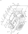
FIG. 1 is a perspective view of a panel mount connector when viewed obliquely from above, -
FIG. 2 is a side view of the panel mount connector, -
FIG. 3 is a side view of a male connector, -
FIG. 4 is a plan view of the male connector, -
FIG. 5 is a side view of a female housing, -
FIG. 6 is a plan view of the female housing, -
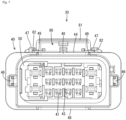
FIG. 7 is a front view of the female housing, -
FIG. 8 is a perspective view of a lever when viewed obliquely from above, -
FIG. 9 is a perspective view of a panel when viewed obliquely from front, -
FIG. 10 is a perspective view of the panel when viewed obliquely from behind, -
FIG. 11 is a plan view of a connection detecting member, -
FIG. 12 is a plan view of the panel mount connector, -
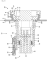
FIG. 13 is a section along A-A ofFIG. 12 , -
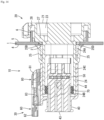
FIG. 14 is a section along B-B ofFIG. 12 , -
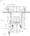
FIG. 15 is a section along C-C ofFIG. 12 , -
FIG. 16 is a section showing the panel mount connector cut at a cutting position ofFIG. 14 when a lever is at a connection start position, -
FIG. 17 is a section showing the panel mount connector cut at the cutting position ofFIG. 14 while the lever is moving from the connection start position to a connection end position, and -
FIG. 18 is a section of the panel mount connector cut at the cutting position ofFIG. 14 when the connection detecting member is at a detection position. - First, embodiments of the present disclosure are listed and described.
- (1) The panel mount connector of the present disclosure is mounted on a panel including a connector mounting hole and provided with a male connector including an inner receptacle projecting from a base end part toward a tip part and open in the tip part, the male connector being mounted on the panel while passing through the connector mounting hole, and a female connector including an outer receptacle to be fit to an outer peripheral surface side of the inner receptacle, the inner receptacle including a panel lock provided at a position closer to the base end part than the tip part, the male connector being held mounted on the panel by locking the panel lock to a peripheral edge part of the connector mounting hole.
The tip part of the inner receptacle is open and more easily deformed than the base end part having no opening. Thus, if the panel lock is provided on the tip part of the inner receptacle, the locking of the panel lock may be released as the inner receptacle is deformed, and the male connector may be detached from the panel. In that respect, since the panel lock is provided at the position closer to the base end part than the tip part in the inner receptacle in the panel mount connector of the present disclosure, the inner receptacle is not deformed at the position of the panel lock, the locking of the panel is not released and the male connector can be held not to be detached from the panel. - (2) Preferably, the panel lock includes a lock body portion provided displaceably with respect to an outer peripheral surface of the inner receptacle and an expanded portion formed by expanding a part of the lock body portion along the outer peripheral surface of the inner receptacle, and the outer receptacle includes a displacement suppressing portion for suppressing a displacement of the lock body portion by being disposed along a facing surface of the expanded portion facing the inner receptacle with the male connector mounted on the panel.
Since the displacement suppressing portion is disposed along the facing surface of the expanded portion facing the inner receptacle, a displacement of the lock body portion is suppressed by the interference of the expanded portion with the displacement suppressing portion if the lock body portion is displaced toward the inner receptacle. Therefore, the locking of the panel lock is not released and the male connector can be held not to be detached from the panel. That is, the panel lock can be secondarily locked by being locked and held by the displacement suppressing portion in addition to being locked and held by preventing the deformation of the inner receptacle. - (3) Preferably, the outer receptacle is provided with a cutout for avoiding interference with the panel lock with the male connector and the female connector connected, and the displacement suppressing portion is provided on a peripheral edge part of the cutout in the outer receptacle.
If the male connector and the female connector are connected, the panel lock is disposed in the cutout of the outer receptacle and the expanded portion is disposed at a position capable of interfering with the displacement suppressing portion. Since the peripheral edge part of the cutout functions as the displacement suppressing portion by providing the cutout in the outer receptacle in this way, the displacement suppressing portion may not be provided separately from the cutout. - (4) Preferably, the displacement suppressing portion is disposed between the expanded portion and the inner receptacle when connection of the male connector and the female connector is completed.
- The complete connection of the male connector and the female connector can guarantee that detachment from the panel is prevented.
- A specific example of a
panel mount connector 10 according to the present disclosure is described below with reference to the drawings. Note that the present disclosure is not limited to these illustrations, but is represented by claims and intended to include all changes in the scope of claims and in the meaning and scope of equivalents. - As shown in
FIG. 1 , thepanel mount connector 10 of the present disclosure is a connector to be mounted on apanel 1 and provided with amale connector 20 and afemale connector 30 connectable to themale connector 20. As shown inFIGS. 9 and10 , thepanel 1 is provided with aconnector mounting hole 2. Themale connector 20 is a standby-side connector mounted on thepanel 1 in advance while being inserted through theconnector mounting hole 2. Note that a front-rear direction is based on a connecting direction of themale connector 20 and thefemale connector 30 and connection surface sides thereof are front sides. - As shown in
FIG. 9 , a pair ofbases 3 are provided on both sides of theconnector mounting hole 2 of thepanel 1. A surface of thepanel 1 on the side of thebases 3 is afront surface 4, and a surface of thepanel 1 opposite to thebases 3 is aback surface 5. As shown inFIG. 10 , apanel receptacle 6 is provided to project rearward on theback surface 5 of thepanel 1. Thepanel receptacle 6 is a receptacle open rearward and having a rectangular shape long in a lateral direction in a front view. Four corners of thepanel receptacle 6 are rounded. - As shown in
FIG. 15 , themale connector 20 is provided with amale housing 21 and a plurality of male terminals (not shown). Themale housing 21 is made of synthetic resin and includes amale housing body 23 formed with a plurality ofcavities 22 for accommodating the respective male terminals and aninner receptacle 24 provided to project forward from the peripheral edge of the front surface of themale housing body 23. Theinner receptacle 24 includes an inner receptaclebase end part 24A, which is a base end part of theinner receptacle 24, an innerreceptacle tip part 24B, which is a tip part of theinner receptacle 24, and an inner receptacleintermediate part 24C, which is an intermediate part between the inner receptaclebase end part 24A and the innerreceptacle tip part 24B. - The
inner receptacle 24 is a receptacle projecting from the inner receptaclebase end part 24A toward the innerreceptacle tip part 24B and open forward in the innerreceptacle tip part 24B. As shown inFIG. 13 , theinner receptacle 24 has a rectangular shape long in the lateral direction in a front view and four corners thereof are rounded. - As shown in
FIG. 15 , aflange 27 is provided on an outer peripheral side of themale housing body 23 in themale housing 21. Theflange 27 is provided over an entire periphery to protrude from the outer peripheral surface of themale housing body 23. Afitting recess 28, into which thepanel receptacle 6 is fit, is provided on an outer peripheral side of theflange 27. Thefitting recess 28 is provided over an entire periphery to protrude from the outer peripheral surface of theflange 27. As shown inFIG. 4 , a pair of cam pins 29 are provided on both left and right sides on the outer peripheral surface of theinner receptacle 24. - As shown in
FIG. 3 , a pair of panel locks 25 are provided on both upper and lower sides on the outer peripheral surface of theinner receptacle 24. Thepanel lock 25 includes a lockbase end part 25A projecting in a vertical direction from the outer peripheral surface of theinner receptacle 24, alock body portion 25B cantilevered rearward from the lockbase end part 25A toward a lockfree end part 25C, and a lockingprotrusion 25D projecting toward a side opposite to theinner receptacle 24 from the lockfree end part 25C. - The lock
base end part 25A is provided near the inner receptacleintermediate part 24C on the outer peripheral surface of theinner receptacle 24. More particularly, the lockbase end part 25A is provided at a position closer to the inner receptaclebase end part 24A on the inner receptacleintermediate part 24C. Therefore, a length from the lockbase end part 25A to the inner receptaclebase end part 24A is shorter than a length from the lockbase end part 25A to the innerreceptacle tip part 24B. - The lock
free end part 25C is provided on an outer peripheral side of the inner receptaclebase end part 24A. Thelock body portion 25B is provided such that the lockfree end part 25C is deflectable in directions toward and away from the outer peripheral surface of theinner receptacle 24 with the lockbase end part 25A as a fulcrum. In this way, the lockingprotrusion 25D is displaceable with respect to the outer peripheral surface of theinner receptacle 24. - As shown in
FIG. 4 , a pair of expandedportions 26 are provided on both side edges of thelock body portion 25B. The expandedportions 26 are parts formed by expanding parts of the side edges of thelock body portion 25B laterally along the outer peripheral surface of theinner receptacle 24. Laterally mentioned here means a direction orthogonal to the front-rear direction (connecting direction). The expandedportions 26 are provided in a central part of thelock body portion 25B in the front-rear direction. A length in the front-rear direction of the expandedportion 26 is about half the length in the front-rear direction of thelock body portion 25B. - A length between the both side edges of the
lock body portion 25B (i.e. a width of thelock body portion 25B) is smaller than a length from the side edge of one expandedportion 26 to the side edge of the other expandedportion 26. All of a width of the lockbase end part 25A, that of thelock body portion 25B, that of the lockfree end part 25C and that of the lockingprotrusion 25D are the same. - As show in
FIGS. 14 and15 , thefemale connector 30 is provided with afemale housing 40, a plurality of female terminals (not shown), aside retainer 50, alever 60, a sealingring 70 and aconnection detecting member 80. Thefemale housing 40 is made of synthetic resin and includes, as shown inFIGS. 5 and7 , afemale housing body 43, anouter receptacle 44 disposed on an outer peripheral side of thefemale housing body 43, alever lock 45 disposed on an upper side of the outer peripheral surface of theouter receptacle 44, and a pair oflever support shafts 46 disposed on both left and right sides on the outer peripheral surface of theouter receptacle 44. - The
female housing body 43 includes a plurality ofcavities 41 for accommodating the respective female terminals and aretainer mounting hole 42, into which theside retainer 50 is mounted. Theside retainer 50 is mounted movably between a temporary locking position and a complete locking position in theretainer mounting hole 42. When theside retainer 50 is at the temporary locking position, the respective female terminals are insertable into therespective cavities 41. If theside retainer 50 is moved from the temporary locking position to the complete locking position with the respective female terminals inserted in therespective cavities 41, the respective female terminals are collectively retained by theside retainer 50. - As shown in
FIG. 15 , theouter receptacle 44 is open forward, and abase end part 44A of theouter receptacle 44 is coupled to the outer peripheral surface of thefemale housing body 43. With themale connector 20 and thefemale connector 30 connected, thefemale housing body 43 is fit inside theinner receptacle 24 and theinner receptacle 24 is ft between theouter receptacle 44 and thefemale housing body 43. That is, theouter receptacle 44 is fit to an outer peripheral side of theinner receptacle 24. - The
lever 60 is rotatably mounted on the pair oflever support shafts 46. Thelever 60 is rotatable between a connection start position shown inFIG. 16 and a connection end position shown inFIG. 15 . With thelever 60 located at the connection end position, thelever 60 is held at the connection end position by thelever lock 45. On the other hand, theconnection detecting member 80 is mounted on thelever lock 45 and movable between an initial position shown inFIG. 14 and a detection position shown inFIG. 18 . - With the
lever 60 held at the connection end position by thelever lock 45, theconnection detecting member 80 is movable from the initial position to the detection position and it can be guaranteed that a connection completed state is reached if theconnection detecting member 80 can be moved to the detection position. The locking by thelever lock 45 cannot be released with theconnection detecting member 80 located at the detection position, and the locking by thelever lock 45 can be released with theconnection detecting member 80 located at the initial position. Therefore, thelever 60 becomes movable from the connection end position to the connection start position by releasing the locking by thelever lock 45. - As shown in
FIG. 6 , acutout 48 is provided in a front end part of theouter receptacle 44. With themale connector 20 and thefemale connector 30 connected, the panel locks 25 are accommodated in thecutout 48 as shown inFIG. 1 . Parts on both left and right sides, out of a peripheral edge part of thecutout 48, serve asdisplacement suppressing portions 49, and thedisplacement suppressing portions 49 are disposed along facing surfaces of the expandedportions 26 facing theinner receptacle 24. That is, thedisplacement suppressing portions 49 are disposed between the expandedportions 26 and theinner receptacle 24. A dimension of a gap between the expandedportion 26 and theinner receptacle 24 is equal to a plate thickness of thedisplacement suppressing portion 49. In this way, if thepanel lock 25 is deflected toward theinner receptacle 24, the deflection of thepanel lock 25 is suppressed since displacements of the expandedportions 26 toward theinner receptacle 24 are suppressed by thedisplacement suppressing portions 49. Therefore, it is suppressed that the locking by the panel locks 25 is released and the detachment of themale connector 20 from thepanel 1 can be suppressed. - The
lever 60 is made of synthetic resin and, as shown inFIG. 8 , gate-shaped as a whole. Thelever 60 includes a pair oflever bodies 61 arranged to face each other and alever operating portion 62 coupling end parts of the pair oflever bodies 61. Acam groove 63 is formed in the inner surface of thelever body 61. Alever shaft hole 65 is provided to penetrate through an end part of thelever body 61 on a side opposite to thelever operating portion 62. - As shown in
FIG. 1 , thelever support shafts 46 of theouter receptacle 44 rotatably support thelever 60 by being fit into the lever shaft holes 65 from inside. Specifically, thelever 60 is rotatable between the connection start position shown inFIG. 18 and the connection end position shown inFIG. 14 by operating thelever operating portion 62. If thelever 60 is rotated from the connection start position to the connection end position, themale connector 20 and thefemale connector 30 are connected to each other by the cam pins 29 being engaged with the inner walls ofcam grooves 63 as shown inFIG. 17 . If thelever 60 is rotated from the connection end position to the connection start position, themale connector 20 and thefemale connector 30 are separated from each other by the cam pins 29 being engaged with the inner walls ofcam grooves 63. - As shown in
FIG. 8 , thelever operating portion 62 is provided with a pair oflock receiving portions 64. Thelever 60 is held at the connection end position by locking thelever lock 45 to thelock receiving portions 64. Conversely, in separating thefemale connector 30 from themale connector 20, thelever 60 is allowed to rotate from the connection end position to the connection start position after theconnection detecting member 80 is moved from the detection position to the initial position and the locking of thelever lock 45 is released. - The sealing
ring 70 is a resilient member made of rubber or the like and configured into an annular shape. As shown inFIG. 15 , the sealingring 70 is mounted on the outer peripheral surface of thefemale housing body 43. With themale connector 20 and thefemale connector 30 connected, the sealingring 70 is sandwiched over an entire periphery by the inner peripheral surface of the innerreceptacle tip part 24B of theinner receptacle 24 and the outer peripheral surface of thefemale housing body 43. In this way, sealing is provided between themale connector 20 and thefemale connector 30. - The
connection detecting member 80 is made of synthetic resin and includes, as shown inFIG. 11 , apressing portion 81 pressable by fingers, a pair ofslide portions 82 provided on both sides of thepressing portion 81 and a detectingportion 83 extending in a pressing direction from thepressing portion 81. As shown inFIG. 15 , theslide portions 82 are guided in the front-rear direction byrail portions 47 provided on the upper surface of theouter receptacle 44. In this way, theconnection detecting member 80 is slidable between the initial position and the detection position. - The
connection detecting member 80 is suppressed from moving to the detection position by an unillustrated projection at the initial position, but the locking by the projection is released and theconnection detecting member 80 is allowed to move to the detection position when thelever 60 reaches the connection end position. Further, by a movement of theconnection detecting member 80 from the detection position to the initial position, the tip of thelever lock 45 is swung and displaced in a direction separating from theouter receptacle 44 by the detectingportion 83. In this way, the locking by thelever lock 45 is released and thelever 60 is enabled to move from the connection end position to the connection start position. - Next, the operation of the
panel mount connector 10 is described. As shown inFIG. 18 , themale connector 20 is inserted into theconnector mounting hole 2 from the side of theback surface 5 of thepanel 1. If the lockingprotrusions 25D of the panel locks 25 are inserted into theconnector mounting hole 2, thelock body portions 25B are deflected toward theinner receptacle 24 while tapered surfaces of the lockingprotrusions 25D slide in contact with a hole edge part of theconnector mounting hole 2. If the lockingprotrusions 25D pass through thepanel 1, thelock body portions 25B resiliently return and locking surfaces of the lockingprotrusions 25D are locked to thefront surface 4 of thepanel 1. In this way, themale connector 20 is mounted on thepanel 1 while passing through theconnector mounting hole 2. - Since the
panel 1 is sandwiched between the lockingprotrusions 25D and theflange 27, themale connector 20 is held mounted on thepanel 1. Simultaneously, thepanel receptacle 6 is accommodated into thefitting recess 28 and comes into contact with the inner peripheral surface of thefitting recess 28. Thus, the inclination of themale connector 20 with respect to thepanel 1 is suppressed. Therefore, it can be avoided that the panel locks 25 are deformed to be unlocked by the inclination of themale connector 20. - Even if the inner
receptacle tip part 24B of theinner receptacle 24 is deflected and deformed due to the application of an excessive force to themale connector 20, the locking by the panel locks 25 is kept since a part of the inner receptacleintermediate part 24C closer to the inner receptaclebase end part 24A is higher in rigidity than the innerreceptacle tip part 24B and is not deflected and deformed. Therefore, themale connector 20 is not detached from thepanel 1 due to the deformation of the innerreceptacle tip part 24B. - Next, a connecting operation of the
male connector 20 and thefemale connector 30 is described. As shown inFIG. 16 , the bothconnectors male connector 20 enter the entrances of the pair ofcam grooves 63 of thelever 60 at the start of connection. Subsequently, if thelever 60 is rotated from the connection start position toward the connection end position, the cam pins 29 are engaged with the inner walls of thecam grooves 63 as shown inFIG. 17 , whereby the connection of the bothconnectors - If the
lock receiving portions 64 of thelever 60 start to engage thelever lock 45, thedisplacement suppressing portions 49 of theouter receptacle 44 are arranged in front of the expandedportions 26. That is, thedisplacement suppressing portions 49 enter between the expandedportions 26 and theinner receptacle 24 after the locking of thelock receiving portions 64 and thelever lock 45 is started. If themale connector 20 and thefemale connector 30 are connected, thelever lock 45 is locked to thelock receiving portions 64, whereby thelever 60 is held at the connection end position. Simultaneously, thedisplacement suppressing portions 49 are disposed between the expandedportions 26 and theinner receptacle 24 and the panel locks 25 are secondarily locked to suppress displacements of the lockingprotrusions 25D of the panel locks 25. Thus, the bothconnectors panel 1. - Subsequently, the
connection detecting member 80 is moved from the initial position to the detection position. If theconnection detecting member 80 can be moved to the detection position, it becomes evidence for the complete connection of the bothconnectors connectors connection detecting member 80 is kept locked by the unillustrated projection. Thus, theconnection detecting member 80 cannot be moved from the initial position to the detection position and the bothconnectors - With the
connection detecting member 80 located at the detection position, thelever lock 45 has already returned to a natural state. Thus, the locking of thelever lock 45 and thelock receiving portions 64 is kept. On the other hand, at the time of separating the bothconnectors connection detecting member 80 is moved from the detection position to the initial position, whereby the locking by thelever lock 45 is released and thelever 60 can be moved from the connection end position to the connection start position. If thelever 60 reaches the connection start position, the separation of the bothconnectors - The
panel mount connector 10 is to be mounted on thepanel 1 including theconnector mounting hole 2, and provided with themale connector 20 including theinner receptacle 24 projecting from the inner receptaclebase end part 24A toward the edgereceptacle tip part 24B and open in the innerreceptacle tip part 24B, themale connector 20 being mounted on the panel while passing through theconnector mounting hole 2, and thefemale connector 30 including theouter receptacle 44 to be fit to the outer peripheral surface side of theinner receptacle 24. Theinner receptacle 24 includes the lever locks 25 provided at the positions closer to the inner receptaclebase end part 24A than the innerreceptacle tip part 24B and to be locked to the peripheral edge part of theconnector mounting hole 2 from the side of thefront surface 4 of thepanel 1, whereby themale connector 20 is held in the state mounted on thepanel 1. - The inner
receptacle tip part 24B of theinner receptacle 24 is open, and more easily deformed than the inner receptaclebase end part 24A having no opening. Thus, if the panel lock is provided on the inner receptacle tip part of the inner receptacle, the locking of the panel lock may be released as the inner receptacle is deformed and the male connector may be detached from thepanel 1. In that respect, since the panel locks 25 are provided at the positions closer to the inner receptaclebase end part 24A than the innerreceptacle tip part 24B in theinner receptacle 24 in thepanel mount connector 10 of the present disclosure, theinner receptacle 24 is not deformed at the positions of the panel locks 25, the locking of the panel locks 25 is not released and themale connector 20 can be held not to be detached from thepanel 1. - Preferably, the
panel lock 25 includes thelever body portion 25B provided displaceably with respect to the outer peripheral surface of theinner receptacle 24 and the expandedportions 26 formed by expanding the parts of thelever body portion 25B along the outer peripheral surface of theinner receptacle 24, and theouter receptacle 44 includes thedisplacement suppressing portions 49 for suppressing displacements of thelever body portions 25B by being disposed along the facing surfaces of the expandedportions 26 facing theinner receptacle 24 with themale connector 20 mounted on thepanel 1. - Since the
displacement suppressing portions 49 are disposed along the facing surfaces of the expandedportions 26 facing theinner receptacle 24, displacements of thelever body portions 25B are suppressed by the interference of the expandedportions 26 with thedisplacement suppressing portions 49 if thelever body portions 25B are displaced toward theinner receptacle 24. Therefore, the locking of the panel locks 25 is not released and themale connector 20 can be held not to be detached from thepanel 1. That is, the panel locks 25 can be secondarily locked by being locked and held by thedisplacement suppressing portions 49 in addition to being locked and held by preventing the deformation of theinner receptacle 24. - Preferably, the
outer receptacle 44 is provided with thecutout 48 for avoiding interference with the panel locks 25 with themale connector 20 and thefemale connector 30 connected, and thedisplacement suppressing portions 49 are provided on the peripheral edge part of thecutout 48 in theouter receptacle 44. - If the
male connector 20 and thefemale connector 30 are connected, the panel locks 25 are disposed in thecutout 48 of theouter receptacle 44 and the expandedportions 26 are disposed at positions capable of interfering with thedisplacement suppressing portions 49. Since the peripheral edge part of thecutout 48 can function as thedisplacement suppressing portions 49 by providing theouter receptacle 44 with thecutout 48 in this way, the displacement suppressing portions may not be provided separately from thecutout 48. - The
displacement suppressing portions 49 are preferably disposed between the expandedportions 26 and theinner receptacle 24 when the connection of themale connector 20 and thefemale connector 30 is completed. - The complete connection of the
male connector 20 and thefemale connector 30 can guarantee that detachment from thepanel 1 is prevented. -
- (1) Although the secondary locking is effected by the
displacement suppressing portions 49 in the above embodiment, the displacement suppressing portions may not necessarily be provided. - (2) Although the dimension of the gap between the expanded
portion 26 and theinner receptacle 24 is equal to the plate thickness of thedisplacement suppressing portion 49 in the above embodiment, the plate thickness of the displacement suppressing portion may be smaller than the dimension of the gap between the expandedportion 26 and theinner receptacle 24. That is, it is sufficient to suppress a displacement of the expandedportion 26 by disposing the displacement suppressing portion along the facing surface of the expandedportion 26 facing theinner receptacle 24, and a gap may be present between the displacement suppressing portion and theinner receptacle 24. - (3) Although the
cutout 48 is provided in the front end part of theouter receptacle 44 in the above embodiment, the front end of the outer receptacle may be located at a position not to interfere with the panel locks 25 and displacement suppressing portions may be provided to extend downwardly of the expandedportions 26 from the front end of the outer receptacle. - (4) Although the
displacement suppressing portions 49 enter between the expandedportions 26 and theinner receptacle 24 after thelever lock 45 is locked to thelock receiving portions 64 in the above embodiment, thedisplacement suppressing portions 49 may enter between the expandedportions 26 and theinner receptacle 24 before thelever lock 45 is locked to thelock receiving portions 64. - (5) Although the panel locks 25 for holding the
male connector 20 mounted on thepanel 1 by being locked to the peripheral edge part of theconnector mounting hole 2 from the side of thefront surface 4 of thepanel 1 has been illustrated in the above embodiment, the panel locks may hold the male connector mounted on thepanel 1 by being locked to the peripheral edge part of theconnector mounting hole 2 from the side of theback surface 5 of thepanel 1. In that case, the flange may be disposed on the side of thefront surface 4 of thepanel 1. -
- 1: panel, 2: connector mounting hole, 3: base, 4: front surface, 5: back surface, 6: panel receptacle
- 10: panel mount connector
- 20: male connector, 21: male housing, 22: cavity, 23: male housing body, 24: inner receptacle, 24A: inner receptacle base end part (base end part), 24B: inner receptacle tip part (tip part), 24C: inner receptacle intermediate part, 25: panel lock, 25A: lock base end part, 25B: lock body portion, 25C: free end part, 25D: locking protrusion, 26: expanded portion, 27: flange, 28: fitting recess, 29: cam pin
- 30: female connector
- 40: female housing, 41: cavity, 42: retainer mounting hole, 43: female housing body, 44: outer receptacle, 44A: base end part, 45: lever lock, 46: lever support shaft, 47: rail portion, 48: cutout, 49: displacement suppressing portion,
- 50: side retainer
- 60: lever, 61: lever body, 62: lever operating portion, 63: cam groove, 64: lock receiving portion, 65: lever shaft hole
- 70: sealing ring
- 80: connection detecting member, 81: pressing portion, 82: slide portion, 83: detecting portion
Claims (4)
- A panel mount connector to be mounted on a panel including a connector mounting hole, comprising:a male connector including an inner receptacle projecting from a base end part toward a tip part and open in the tip part, the male connector being mounted on the panel while passing through the connector mounting hole; anda female connector including an outer receptacle to be fit to an outer peripheral surface side of the inner receptacle,the inner receptacle including a panel lock provided at a position closer to the base end part than the tip part, the male connector being held mounted on the panel by locking the panel lock to a peripheral edge part of the connector mounting hole.
- The panel mount connector of claim 1, wherein:the panel lock includes a lock body portion provided displaceably with respect to an outer peripheral surface of the inner receptacle and an expanded portion formed by expanding a part of the lock body portion along the outer peripheral surface of the inner receptacle, andthe outer receptacle includes a displacement suppressing portion for suppressing a displacement of the lock body portion by being disposed along a facing surface of the expanded portion facing the inner receptacle with the male connector mounted on the panel.
- The panel mount connector of claim 2, wherein:the outer receptacle is provided with a cutout for avoiding interference with the panel lock with the male connector and the female connector connected, andthe displacement suppressing portion is provided on a peripheral edge part of the cutout in the outer receptacle.
- The panel mount connector of claim 2 or 3, wherein the displacement suppressing portion is disposed between the expanded portion and the inner receptacle when connection of the male connector and the female connector is completed.
Applications Claiming Priority (2)
| Application Number | Priority Date | Filing Date | Title |
|---|---|---|---|
| JP2021032514A JP2022133687A (en) | 2021-03-02 | 2021-03-02 | Panel-mounting type connector |
| PCT/JP2022/006112 WO2022185913A1 (en) | 2021-03-02 | 2022-02-16 | Panel-mounted connector |
Publications (2)
| Publication Number | Publication Date |
|---|---|
| EP4304020A1 true EP4304020A1 (en) | 2024-01-10 |
| EP4304020A4 EP4304020A4 (en) | 2024-07-31 |
Family
ID=83154037
Family Applications (1)
| Application Number | Title | Priority Date | Filing Date |
|---|---|---|---|
| EP22762970.6A Pending EP4304020A4 (en) | 2021-03-02 | 2022-02-16 | PANEL MOUNTED CONNECTOR |
Country Status (4)
| Country | Link |
|---|---|
| EP (1) | EP4304020A4 (en) |
| JP (1) | JP2022133687A (en) |
| CN (1) | CN116918190A (en) |
| WO (1) | WO2022185913A1 (en) |
Family Cites Families (10)
| Publication number | Priority date | Publication date | Assignee | Title |
|---|---|---|---|---|
| JPH0587853U (en) * | 1992-04-28 | 1993-11-26 | 日本エー・エム・ピー株式会社 | Electrical connector |
| JP2567848Y2 (en) * | 1992-10-08 | 1998-04-08 | 住友電装株式会社 | connector |
| JP3140336B2 (en) * | 1995-08-01 | 2001-03-05 | 矢崎総業株式会社 | Movable connector mounting structure |
| JP3541695B2 (en) * | 1998-11-11 | 2004-07-14 | 住友電装株式会社 | Panel mount type connector |
| DE29823075U1 (en) * | 1998-12-24 | 2000-05-04 | Grote & Hartmann Gmbh & Co Kg, 42369 Wuppertal | Connector housing connector |
| JP3567856B2 (en) * | 2000-06-08 | 2004-09-22 | 住友電装株式会社 | Connector support structure |
| JP3887695B2 (en) | 2001-12-17 | 2007-02-28 | 住友電装株式会社 | connector |
| JP3944179B2 (en) * | 2004-03-12 | 2007-07-11 | 矢崎総業株式会社 | connector |
| JP2007134292A (en) * | 2005-11-14 | 2007-05-31 | Jst Mfg Co Ltd | Electrical connector |
| JP2017188393A (en) * | 2016-04-08 | 2017-10-12 | 矢崎総業株式会社 | connector |
-
2021
- 2021-03-02 JP JP2021032514A patent/JP2022133687A/en active Pending
-
2022
- 2022-02-16 EP EP22762970.6A patent/EP4304020A4/en active Pending
- 2022-02-16 WO PCT/JP2022/006112 patent/WO2022185913A1/en not_active Ceased
- 2022-02-16 CN CN202280013125.0A patent/CN116918190A/en active Pending
Also Published As
| Publication number | Publication date |
|---|---|
| WO2022185913A1 (en) | 2022-09-09 |
| JP2022133687A (en) | 2022-09-14 |
| EP4304020A4 (en) | 2024-07-31 |
| CN116918190A (en) | 2023-10-20 |
Similar Documents
| Publication | Publication Date | Title |
|---|---|---|
| US7300294B2 (en) | Connector and connector assembly of the movable member type | |
| KR100987484B1 (en) | connector | |
| JP6036661B2 (en) | Waterproof connector | |
| US10707616B2 (en) | Connector assembly with a lever and a lever lock for releasably locking the lever in a connection end position | |
| US10826238B2 (en) | Connector and connector assembly | |
| US6733313B2 (en) | Connector having an operable member and a connector assembly | |
| US7108542B2 (en) | Connector apparatus with a mating detecting member called connector position assurance | |
| US20220271473A1 (en) | Connector | |
| US9997863B2 (en) | Connector | |
| US11329426B2 (en) | Connector | |
| US10944198B2 (en) | Connector | |
| CN111834836A (en) | connector with grommets | |
| US10910765B2 (en) | Lever-type connector | |
| US10566737B2 (en) | Connector and connector assembly | |
| US10468821B2 (en) | Lever-type connector | |
| JP2011142050A (en) | Lever-type connector | |
| JPH1050384A (en) | connector | |
| US20230396021A1 (en) | Lever-type connector | |
| US6638099B2 (en) | Connector | |
| EP1916746B1 (en) | A connector | |
| US11114801B2 (en) | Connector | |
| EP3806246A1 (en) | Lever-type connector | |
| US11081839B2 (en) | Connector with high reliability of returning a protection member to a partial locking position | |
| US20200335897A1 (en) | Grommet-equipped connector | |
| CN116918190A (en) | Panel mount connector |
Legal Events
| Date | Code | Title | Description |
|---|---|---|---|
| STAA | Information on the status of an ep patent application or granted ep patent |
Free format text: STATUS: THE INTERNATIONAL PUBLICATION HAS BEEN MADE |
|
| PUAI | Public reference made under article 153(3) epc to a published international application that has entered the european phase |
Free format text: ORIGINAL CODE: 0009012 |
|
| STAA | Information on the status of an ep patent application or granted ep patent |
Free format text: STATUS: REQUEST FOR EXAMINATION WAS MADE |
|
| 17P | Request for examination filed |
Effective date: 20230918 |
|
| AK | Designated contracting states |
Kind code of ref document: A1 Designated state(s): AL AT BE BG CH CY CZ DE DK EE ES FI FR GB GR HR HU IE IS IT LI LT LU LV MC MK MT NL NO PL PT RO RS SE SI SK SM TR |
|
| DAV | Request for validation of the european patent (deleted) | ||
| DAX | Request for extension of the european patent (deleted) | ||
| A4 | Supplementary search report drawn up and despatched |
Effective date: 20240627 |
|
| RIC1 | Information provided on ipc code assigned before grant |
Ipc: H01R 13/629 20060101ALN20240621BHEP Ipc: H01R 13/74 20060101AFI20240621BHEP |