EP4303992A1 - Battery rack and energy storage system comprising battery rack - Google Patents
Battery rack and energy storage system comprising battery rack Download PDFInfo
- Publication number
- EP4303992A1 EP4303992A1 EP22842496.6A EP22842496A EP4303992A1 EP 4303992 A1 EP4303992 A1 EP 4303992A1 EP 22842496 A EP22842496 A EP 22842496A EP 4303992 A1 EP4303992 A1 EP 4303992A1
- Authority
- EP
- European Patent Office
- Prior art keywords
- battery pack
- battery
- coolant
- frame
- rack according
- Prior art date
- Legal status (The legal status is an assumption and is not a legal conclusion. Google has not performed a legal analysis and makes no representation as to the accuracy of the status listed.)
- Pending
Links
Images




Classifications
-
- H—ELECTRICITY
- H01—ELECTRIC ELEMENTS
- H01M—PROCESSES OR MEANS, e.g. BATTERIES, FOR THE DIRECT CONVERSION OF CHEMICAL ENERGY INTO ELECTRICAL ENERGY
- H01M10/00—Secondary cells; Manufacture thereof
- H01M10/60—Heating or cooling; Temperature control
- H01M10/65—Means for temperature control structurally associated with the cells
- H01M10/656—Means for temperature control structurally associated with the cells characterised by the type of heat-exchange fluid
- H01M10/6567—Liquids
-
- A—HUMAN NECESSITIES
- A62—LIFE-SAVING; FIRE-FIGHTING
- A62C—FIRE-FIGHTING
- A62C3/00—Fire prevention, containment or extinguishing specially adapted for particular objects or places
- A62C3/16—Fire prevention, containment or extinguishing specially adapted for particular objects or places in electrical installations, e.g. cableways
-
- A—HUMAN NECESSITIES
- A62—LIFE-SAVING; FIRE-FIGHTING
- A62C—FIRE-FIGHTING
- A62C35/00—Permanently-installed equipment
- A62C35/58—Pipe-line systems
-
- A—HUMAN NECESSITIES
- A62—LIFE-SAVING; FIRE-FIGHTING
- A62C—FIRE-FIGHTING
- A62C99/00—Subject matter not provided for in other groups of this subclass
-
- A—HUMAN NECESSITIES
- A62—LIFE-SAVING; FIRE-FIGHTING
- A62C—FIRE-FIGHTING
- A62C99/00—Subject matter not provided for in other groups of this subclass
- A62C99/0009—Methods of extinguishing or preventing the spread of fire by cooling down or suffocating the flames
- A62C99/0072—Methods of extinguishing or preventing the spread of fire by cooling down or suffocating the flames using sprayed or atomised water
-
- H—ELECTRICITY
- H01—ELECTRIC ELEMENTS
- H01M—PROCESSES OR MEANS, e.g. BATTERIES, FOR THE DIRECT CONVERSION OF CHEMICAL ENERGY INTO ELECTRICAL ENERGY
- H01M10/00—Secondary cells; Manufacture thereof
- H01M10/42—Methods or arrangements for servicing or maintenance of secondary cells or secondary half-cells
- H01M10/48—Accumulators combined with arrangements for measuring, testing or indicating the condition of cells, e.g. the level or density of the electrolyte
-
- H—ELECTRICITY
- H01—ELECTRIC ELEMENTS
- H01M—PROCESSES OR MEANS, e.g. BATTERIES, FOR THE DIRECT CONVERSION OF CHEMICAL ENERGY INTO ELECTRICAL ENERGY
- H01M10/00—Secondary cells; Manufacture thereof
- H01M10/60—Heating or cooling; Temperature control
- H01M10/61—Types of temperature control
- H01M10/613—Cooling or keeping cold
-
- H—ELECTRICITY
- H01—ELECTRIC ELEMENTS
- H01M—PROCESSES OR MEANS, e.g. BATTERIES, FOR THE DIRECT CONVERSION OF CHEMICAL ENERGY INTO ELECTRICAL ENERGY
- H01M10/00—Secondary cells; Manufacture thereof
- H01M10/60—Heating or cooling; Temperature control
- H01M10/62—Heating or cooling; Temperature control specially adapted for specific applications
- H01M10/625—Vehicles
-
- H—ELECTRICITY
- H01—ELECTRIC ELEMENTS
- H01M—PROCESSES OR MEANS, e.g. BATTERIES, FOR THE DIRECT CONVERSION OF CHEMICAL ENERGY INTO ELECTRICAL ENERGY
- H01M10/00—Secondary cells; Manufacture thereof
- H01M10/60—Heating or cooling; Temperature control
- H01M10/62—Heating or cooling; Temperature control specially adapted for specific applications
- H01M10/627—Stationary installations, e.g. power plant buffering or backup power supplies
-
- H—ELECTRICITY
- H01—ELECTRIC ELEMENTS
- H01M—PROCESSES OR MEANS, e.g. BATTERIES, FOR THE DIRECT CONVERSION OF CHEMICAL ENERGY INTO ELECTRICAL ENERGY
- H01M10/00—Secondary cells; Manufacture thereof
- H01M10/60—Heating or cooling; Temperature control
- H01M10/65—Means for temperature control structurally associated with the cells
- H01M10/656—Means for temperature control structurally associated with the cells characterised by the type of heat-exchange fluid
- H01M10/6567—Liquids
- H01M10/6568—Liquids characterised by flow circuits, e.g. loops, located externally to the cells or cell casings
-
- H—ELECTRICITY
- H01—ELECTRIC ELEMENTS
- H01M—PROCESSES OR MEANS, e.g. BATTERIES, FOR THE DIRECT CONVERSION OF CHEMICAL ENERGY INTO ELECTRICAL ENERGY
- H01M50/00—Constructional details or processes of manufacture of the non-active parts of electrochemical cells other than fuel cells, e.g. hybrid cells
- H01M50/20—Mountings; Secondary casings or frames; Racks, modules or packs; Suspension devices; Shock absorbers; Transport or carrying devices; Holders
- H01M50/204—Racks, modules or packs for multiple batteries or multiple cells
-
- H—ELECTRICITY
- H01—ELECTRIC ELEMENTS
- H01M—PROCESSES OR MEANS, e.g. BATTERIES, FOR THE DIRECT CONVERSION OF CHEMICAL ENERGY INTO ELECTRICAL ENERGY
- H01M50/00—Constructional details or processes of manufacture of the non-active parts of electrochemical cells other than fuel cells, e.g. hybrid cells
- H01M50/20—Mountings; Secondary casings or frames; Racks, modules or packs; Suspension devices; Shock absorbers; Transport or carrying devices; Holders
- H01M50/204—Racks, modules or packs for multiple batteries or multiple cells
- H01M50/207—Racks, modules or packs for multiple batteries or multiple cells characterised by their shape
-
- H—ELECTRICITY
- H01—ELECTRIC ELEMENTS
- H01M—PROCESSES OR MEANS, e.g. BATTERIES, FOR THE DIRECT CONVERSION OF CHEMICAL ENERGY INTO ELECTRICAL ENERGY
- H01M50/00—Constructional details or processes of manufacture of the non-active parts of electrochemical cells other than fuel cells, e.g. hybrid cells
- H01M50/20—Mountings; Secondary casings or frames; Racks, modules or packs; Suspension devices; Shock absorbers; Transport or carrying devices; Holders
- H01M50/249—Mountings; Secondary casings or frames; Racks, modules or packs; Suspension devices; Shock absorbers; Transport or carrying devices; Holders specially adapted for aircraft or vehicles, e.g. cars or trains
-
- H—ELECTRICITY
- H01—ELECTRIC ELEMENTS
- H01M—PROCESSES OR MEANS, e.g. BATTERIES, FOR THE DIRECT CONVERSION OF CHEMICAL ENERGY INTO ELECTRICAL ENERGY
- H01M50/00—Constructional details or processes of manufacture of the non-active parts of electrochemical cells other than fuel cells, e.g. hybrid cells
- H01M50/20—Mountings; Secondary casings or frames; Racks, modules or packs; Suspension devices; Shock absorbers; Transport or carrying devices; Holders
- H01M50/251—Mountings; Secondary casings or frames; Racks, modules or packs; Suspension devices; Shock absorbers; Transport or carrying devices; Holders specially adapted for stationary devices, e.g. power plant buffering or backup power supplies
-
- H—ELECTRICITY
- H01—ELECTRIC ELEMENTS
- H01M—PROCESSES OR MEANS, e.g. BATTERIES, FOR THE DIRECT CONVERSION OF CHEMICAL ENERGY INTO ELECTRICAL ENERGY
- H01M50/00—Constructional details or processes of manufacture of the non-active parts of electrochemical cells other than fuel cells, e.g. hybrid cells
- H01M50/20—Mountings; Secondary casings or frames; Racks, modules or packs; Suspension devices; Shock absorbers; Transport or carrying devices; Holders
- H01M50/298—Mountings; Secondary casings or frames; Racks, modules or packs; Suspension devices; Shock absorbers; Transport or carrying devices; Holders characterised by the wiring of battery packs
-
- H—ELECTRICITY
- H01—ELECTRIC ELEMENTS
- H01M—PROCESSES OR MEANS, e.g. BATTERIES, FOR THE DIRECT CONVERSION OF CHEMICAL ENERGY INTO ELECTRICAL ENERGY
- H01M50/00—Constructional details or processes of manufacture of the non-active parts of electrochemical cells other than fuel cells, e.g. hybrid cells
- H01M50/30—Arrangements for facilitating escape of gases
- H01M50/317—Re-sealable arrangements
- H01M50/325—Re-sealable arrangements comprising deformable valve members, e.g. elastic or flexible valve members
-
- H—ELECTRICITY
- H01—ELECTRIC ELEMENTS
- H01M—PROCESSES OR MEANS, e.g. BATTERIES, FOR THE DIRECT CONVERSION OF CHEMICAL ENERGY INTO ELECTRICAL ENERGY
- H01M50/00—Constructional details or processes of manufacture of the non-active parts of electrochemical cells other than fuel cells, e.g. hybrid cells
- H01M50/30—Arrangements for facilitating escape of gases
- H01M50/342—Non-re-sealable arrangements
- H01M50/3425—Non-re-sealable arrangements in the form of rupturable membranes or weakened parts, e.g. pierced with the aid of a sharp member
-
- H—ELECTRICITY
- H01—ELECTRIC ELEMENTS
- H01M—PROCESSES OR MEANS, e.g. BATTERIES, FOR THE DIRECT CONVERSION OF CHEMICAL ENERGY INTO ELECTRICAL ENERGY
- H01M50/00—Constructional details or processes of manufacture of the non-active parts of electrochemical cells other than fuel cells, e.g. hybrid cells
- H01M50/60—Arrangements or processes for filling or topping-up with liquids; Arrangements or processes for draining liquids from casings
- H01M50/673—Containers for storing liquids; Delivery conduits therefor
-
- H—ELECTRICITY
- H01—ELECTRIC ELEMENTS
- H01M—PROCESSES OR MEANS, e.g. BATTERIES, FOR THE DIRECT CONVERSION OF CHEMICAL ENERGY INTO ELECTRICAL ENERGY
- H01M2200/00—Safety devices for primary or secondary batteries
- H01M2200/10—Temperature sensitive devices
-
- H—ELECTRICITY
- H01—ELECTRIC ELEMENTS
- H01M—PROCESSES OR MEANS, e.g. BATTERIES, FOR THE DIRECT CONVERSION OF CHEMICAL ENERGY INTO ELECTRICAL ENERGY
- H01M2200/00—Safety devices for primary or secondary batteries
- H01M2200/20—Pressure-sensitive devices
-
- H—ELECTRICITY
- H01—ELECTRIC ELEMENTS
- H01M—PROCESSES OR MEANS, e.g. BATTERIES, FOR THE DIRECT CONVERSION OF CHEMICAL ENERGY INTO ELECTRICAL ENERGY
- H01M2220/00—Batteries for particular applications
- H01M2220/10—Batteries in stationary systems, e.g. emergency power source in plant
-
- H—ELECTRICITY
- H01—ELECTRIC ELEMENTS
- H01M—PROCESSES OR MEANS, e.g. BATTERIES, FOR THE DIRECT CONVERSION OF CHEMICAL ENERGY INTO ELECTRICAL ENERGY
- H01M2220/00—Batteries for particular applications
- H01M2220/20—Batteries in motive systems, e.g. vehicle, ship, plane
-
- Y—GENERAL TAGGING OF NEW TECHNOLOGICAL DEVELOPMENTS; GENERAL TAGGING OF CROSS-SECTIONAL TECHNOLOGIES SPANNING OVER SEVERAL SECTIONS OF THE IPC; TECHNICAL SUBJECTS COVERED BY FORMER USPC CROSS-REFERENCE ART COLLECTIONS [XRACs] AND DIGESTS
- Y02—TECHNOLOGIES OR APPLICATIONS FOR MITIGATION OR ADAPTATION AGAINST CLIMATE CHANGE
- Y02E—REDUCTION OF GREENHOUSE GAS [GHG] EMISSIONS, RELATED TO ENERGY GENERATION, TRANSMISSION OR DISTRIBUTION
- Y02E60/00—Enabling technologies; Technologies with a potential or indirect contribution to GHG emissions mitigation
- Y02E60/10—Energy storage using batteries
-
- Y—GENERAL TAGGING OF NEW TECHNOLOGICAL DEVELOPMENTS; GENERAL TAGGING OF CROSS-SECTIONAL TECHNOLOGIES SPANNING OVER SEVERAL SECTIONS OF THE IPC; TECHNICAL SUBJECTS COVERED BY FORMER USPC CROSS-REFERENCE ART COLLECTIONS [XRACs] AND DIGESTS
- Y02—TECHNOLOGIES OR APPLICATIONS FOR MITIGATION OR ADAPTATION AGAINST CLIMATE CHANGE
- Y02W—CLIMATE CHANGE MITIGATION TECHNOLOGIES RELATED TO WASTEWATER TREATMENT OR WASTE MANAGEMENT
- Y02W30/00—Technologies for solid waste management
- Y02W30/50—Reuse, recycling or recovery technologies
- Y02W30/84—Recycling of batteries or fuel cells
Definitions
- the present disclosure relates to a battery rack and san energy storage system comprising the same.
- secondary batteries Due to their characteristics of being easily applicable to various products and electrical properties such as high energy density, secondary batteries are not only commonly applied to portable devices, but universally applied to electric vehicles (EVs) or hybrid electric vehicles (HEVs) that are driven by an electrical driving source.
- EVs electric vehicles
- HEVs hybrid electric vehicles
- secondary batteries do not produce by-products from the use of energy, so they are gaining attention as a new eco-friendly and energy efficient source of energy.
- a unit secondary battery cell or a unit battery cell has an operating voltage of about 2.5V to 4.5V. Accordingly, when a higher output voltage is required, a plurality of battery cells may be connected in series to form a battery pack. Additionally, the battery pack may be fabricated by connecting the plurality of battery cells in parallel according to the charge/discharge capacity required for the battery pack. Accordingly, the number of battery cells included in the battery pack may be variously set depending on the required output voltage or charge/discharge capacity.
- an energy storage system including at least one battery rack is constructed as an energy source.
- the battery pack used in an electric vehicle is used for a predetermined period of time or below a predetermined capacity, in general, the battery pack is wasted due to the reduced driving performance of the vehicle.
- the wasted battery pack includes cobalt oxide, lithium, manganese, nickel or the like, causing environmental pollution or dangers related to fires or electric shocks.
- waste battery packs from electric vehicles may be reused in other applications than the fuel source of vehicles.
- the waste battery packs from electric vehicles may be reused in energy storage systems (ESSs).
- ESSs energy storage systems
- the waste battery packs from electric vehicles for reuse are referred to as reuse battery packs.
- the present disclosure is directed to providing a battery rack for receiving a battery pack for reuse after the use for a predetermined period of time or below a predetermined capacity more stably and ensuring safety when a fire occurs due to an abnormal situation such as overheat, and an energy storage system comprising the same.
- the present disclosure provides a battery rack including at least one battery pack used for a predetermined period of time or below a predetermined capacity; and a battery pack frame accommodating the at least one battery pack, and having a larger height than the at least one battery pack, wherein the at least one battery pack includes a service plug to open an inside of the at least one battery pack.
- a coolant may be injected into the battery pack frame such that a predetermined height of the at least one battery pack is submerged in the coolant when an abnormal situation occurs in the at least one battery pack.
- the service plug may open the inside of the at least one battery pack to guide the direct injection of the coolant into the at least one battery pack when an internal pressure of the at least one battery pack rises above a predetermined pressure in the event of the abnormal situation.
- the service plug may be disposed on an upper surface of the at least one battery pack.
- At least one feed pipe for feeding the coolant may be disposed above the battery pack frame.
- the at least one feed pipe may include at least one spring cooler to spray the coolant onto the at least one battery pack.
- the service plug may be disposed close to the at least one spring cooler.
- the battery pack frame may have at least on cable through-hole portion through which at least one cable for electrical connection to the at least one battery pack passes.
- At least one cable sealing member may be mounted in the at least one cable through-hole portion to prevent a leakage of the coolant.
- the battery pack may be a battery pack used in an electric vehicle or a hybrid electric vehicle.
- the battery rack may include a plurality of the battery packs, and the plurality of battery packs may be stacked on top of each other along a heightwise direction of the battery rack such that they are electrically connected to each other.
- the present disclosure provides an energy storage system including at least one battery rack according to the above-described embodiments.
- a battery rack for receiving a battery pack for reuse after the use for a predetermined period of time or below a predetermined capacity more stably and ensuring safety when a fire occurs due to an abnormal situation such as overheat, and an energy storage system comprising the same.
- FIG. 1 is a diagram illustrating a battery rack according to an embodiment of the present disclosure.
- the battery rack 10 may include at least one battery pack 100 and at least one battery pack frame 200 accommodating the at least one battery pack 100.
- the at least one battery pack 100 may include a service plug 150 to open the at least one battery pack 100 to guide the direct injection of a coolant into the at least one battery pack 100 when the internal pressure of the at least one battery pack 100 rises above a predetermined pressure in the event of an abnormal situation.
- the service plug 150 will be described in more detail below.
- the at least one battery pack 100 may be a battery pack used for a predetermined period of time or below a predetermined capacity. Specifically, the at least one battery pack 100 may be a battery pack used in an electric vehicle or a hybrid electric vehicle. The at least one battery pack may be referred to as a reuse battery pack.
- One or more battery packs 100 may be included. Hereinafter, this embodiment is described based on the plurality of battery packs 100.
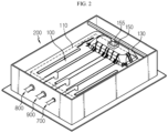
- FIG. 2 is a diagram illustrating the battery pack of the battery rack of FIG. 1 .
- the battery pack 100 may include a battery cell 110, a pack case 130 and the service plug 150.
- the battery cell 110 may include a secondary battery, for example, a pouch type secondary battery, a prismatic secondary battery or a cylindrical secondary battery.
- a secondary battery for example, a pouch type secondary battery, a prismatic secondary battery or a cylindrical secondary battery.
- this embodiment is described by taking a secondary battery, to be exact, a pouch type secondary battery, as an example of the battery cell 110.
- One or more battery cells 110 may be included. Hereinafter, this embodiment is described based on the plurality of battery cells 110 electrically connected to each other to form a battery cell assembly.
- the pack case 130 may accommodate the plurality of battery cells 110 and different types of electrical components and a cooling unit of the battery pack 100. To this end, the pack case 130 may have an accommodation space in which the components of the battery pack 100 are received.
- the service plug 150 is configured to disconnect the electrical connection of the battery pack 100 by the user manipulation to prevent electric shock accidents in the operator's inspection or management of the battery pack 100, and may be mounted in the pack case 130 and electrically connected to the battery cells 110 or the electrical components of the battery pack 100.
- the service plug 150 may open the at least one battery pack 100 to guide the direct injection of the coolant into the at least one battery pack 100 when the internal pressure of the at least one battery pack 100 rises above the predetermined pressure in the event of the abnormal situation.
- the service plug 150 may be disposed on the upper surface of the battery pack 100, i.e., on the pack case 130 to allow the user or the operator to easily manipulate. Furthermore, the service plug 150 may be disposed close to the bottom of the feed pipe 400 on the upper surface of the pack case 130 to smoothly inject the coolant into the battery pack 100 in the event of the abnormal situation. Specifically, the service plug 150 may be disposed close to at least one spring cooler 450 of the feed pipe 400 as described below.
- a plug cover 155 may be disposed above the service plug 150 to open the service plug 150 to make the inside and outside of the pack case 130 of the battery pack 100 communicate with each other when the internal pressure of the battery pack 100 rises above the predetermined pressure.
- the plug cover 155 may operate to open the service plug 150 when the internal pressure of the battery pack 100 rises above the predetermined pressure.
- the opening operation of the plug cover 155 may be performed by a passive or active method.
- the plug cover 155 may be a rotatable structure or a valve structure which is opened at the predetermined pressure, or a rotatable structure or a valve structure which is connected to an electric controller of the battery pack 100 to operate by the control of the electric controller at the predetermined pressure. This is provided for illustrative purpose, and the opening/closing structure of the plug cover 155 may use any other method of opening the service plug 150 when the internal pressure of the battery pack 100 is equal to or higher than the predetermined pressure.
- the at least one battery pack frame 200 may accommodate the at least one battery pack 100 used for the predetermined period of time or below the predetermined capacity, and may have a larger height than the at least one battery pack 100.
- the at least one battery pack frame 200 may be filled with the coolant C such that a predetermined height of the at least one battery pack 100 is submerged in the coolant C.
- the at least one battery pack frame 200 may receive the at least one battery pack 100 used for the predetermined period of time or below the predetermined capacity more stably and control a dangerous situation such as a fire through the coolant C filled inside more quickly when the dangerous situation such as the fire occurs due to the abnormal situation caused by overheat of the at least one battery pack 100.
- a plurality of battery pack frame 200 may be included, and the plurality of battery pack frames 200 may be stacked on top of each other along the heightwise direction of the battery rack 10.
- the at least one battery pack frame 200 will be described in more detail.
- FIG. 3 is a diagram illustrating the battery pack frame of the battery rack of FIG. 1 .
- the battery pack frame 200 may have an accommodation space which is exposed to top, and the at least one battery pack 100 may be received in the accommodation space.
- At least one feed pipe 400 for feeding the coolant C may be disposed above the battery pack frame 200.
- the at least one feed pipe 400 will be described in more detail below.
- At least one smoke detection sensor 500 may be disposed at the upper part of the battery pack frame 200 to detect smoke when an abnormal situation occurs due to the overheat of the at least one battery pack 100.
- the at least one smoke detection sensor 500 will be described in more detail below.
- the at least one smoke detection sensor 500 may be mounted at the upper part of the battery pack frame 200, and a sensor support 600 may be configured to support the at least one smoke detection sensor 500.
- the sensor support 600 will be described in more detail below.
- the battery pack frame 200 may include a water tank frame 210 and a support frame 250.
- the water tank frame 210 may have an accommodation space which is exposed to top, for receiving the at least one battery pack 100, and the accommodation space may be filled with the coolant C (see FIG. 7 ).
- the water tank frame 210 may include at least one cable through-hole portion 212, at least one cable sealing member 214, a cooling inlet through-hole portion 215, a cooling outlet through-hole portion 216, an inlet sealing member 217 and an outlet sealing member 218.
- the at least one cable through-hole portion 212 may be disposed on one side of the battery pack frame 200, to be specific, one side of the water tank frame 210, and may allow at least one cable 700 for electrical connection to the at least one battery pack 100 to pass through.
- the at least one cable sealing member 214 is configured to prevent the leakage of the coolant C through the at least one cable through-hole portion 212, and may be mounted in the at least one cable through-hole portion 212.
- the at least one cable sealing member 214 may be mounted in the at least one cable through-hole portion 212.
- the at least one cable sealing member 214 may prevent the leakage of the coolant C from the water tank frame 210 through the cable through-hole portion 212.
- the cooling inlet through-hole portion 215 may be disposed on one side of the battery pack frame 200, to be specific, one side of the water tank frame 210, and may allow a cooling inlet 800 for cooling of the battery pack 100 to pass through.
- the cooling outlet through-hole portion 216 may be disposed on one side of the battery pack frame 200, to be specific, one side of the water tank frame 210, and may allow a cooling outlet 900 for cooling of the battery pack 100 to pass through.
- the inlet sealing member 217 may be mounted in the cooling inlet through-hole portion 215. When the water tank frame 210 is filled with the coolant C (see FIG. 7 ), the inlet sealing member 217 may prevent the leakage of the coolant C from the water tank frame 210 through the cooling inlet through-hole portion 215.
- the outlet sealing member 218 may be mounted in the cooling outlet through-hole portion 216. When the water tank frame 210 is filled with the coolant C (see FIG. 7 ), the outlet sealing member 218 may prevent the leakage of the coolant C from the water tank frame 210 through the cooling outlet through-hole portion 216.
- the support frame 250 may be disposed below the water tank frame 210, and its edge may extend outward from the bottom edge of the water tank frame 210. That is, the support frame 250 may have a wider area than the bottom area of the water tank frame 210.
- the support frame 250 may ensure the strength of the battery pack frame 200. Furthermore, the support frame 250 may prevent the entry of the coolant C into the water tank frame 210 of the adjacent battery pack frame 200 when the coolant C (see FIG. 8 ) flows over the water tank frame 210.
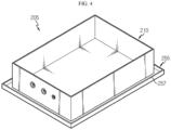
- FIG. 4 is a diagram illustrating a support frame according to another embodiment of the battery pack frame of FIG. 3 .
- the battery pack frame 205 may include a water tank frame 210 and a support frame 255.
- the water tank frame 210 is substantially identical or similar to the previous embodiment, and an overlapping description is omitted.
- the support frame 255 may have a step portion 257 having a predetermined height at its edge to prevent the coolant C from flowing down when the coolant C (see FIG. 9 ) leaks from the water tank frame 210.
- an additional coolant accommodation space may be formed at the edge of the support frame 255 to further hold the coolant C to the predetermined height.
- a drain pipe may be connected to one side of the additional coolant accommodation space at the edge of the support frame 255 to drain the coolant C.
- FIG. 5 is a diagram illustrating the main parts of the battery rack of FIG. 1 .
- the battery rack 10 may further include a rack frame 300, the feed pipe 400, the smoke detection sensor 500, the sensor support 600, the at least one cable 700, the cooling inlet 800 and the cooling outlet 900.
- the rack frame 300 may support the plurality of battery pack frames 200 and guide the vertical stack of the plurality of battery pack frames 200.
- a plurality of feed pipes 400 may be included, and may be disposed above each battery pack frame 200.
- the feed pipes 400 may be connected to a coolant tank (not shown) outside of the battery rack 10.
- Each feed pipe 400 may include at least one spring cooler 450 to spray the coolant C onto the at least one battery pack 100.
- the at least one spring cooler 450 may disposed above the battery pack 100 above the battery pack frame 200.
- One or more spring coolers 450 may be included. Hereinafter, this embodiment is described based on the plurality of spring coolers 450.
- the smoke detection sensor 500 may detect smoke coming out of the battery pack 100 to detect a fire when the fire occurred due to overheat of the battery pack 100.
- the smoke detection sensor 500 may be disposed above the service plug 150 of the battery pack 100 where smoke is highly likely to first come out of the battery pack 100.
- the sensor support 600 is configured to support the smoke detection sensor 500 more stably, and may have a bar shape having a predetermined length and may be mounted in the water tank frame 210 of the battery pack frame 200.
- the at least one cable 700 is used to connect the electrical components inside of the battery pack 100 to an external electrical unit, and may be connected to the battery pack 100.
- the at least one cable 700 may be connected to the battery pack 100 in the water tank frame 210 through the cable through-hole portion 212 of the water tank frame 210 of the battery pack frame 200.
- the at least one cable 700 may have a waterproof sealing coating on the outer surface to prevent an electrical short when the water tank frame 210 is filled with the coolant C (see FIG. 7 ).
- the cooling inlet 800 is used to cool the battery pack 100, and may connect the external cooling unit to the battery pack 100.
- the cooling inlet 800 may be connected to the battery pack 100 in the water tank frame 210 through the cooling inlet through-hole portion 215 of the water tank frame 210.
- the cooling outlet 900 is used to cool the battery pack 100, and may connect the external cooling unit to the battery pack 100.
- the cooling outlet 900 may be connected to the battery pack 100 in the water tank frame 210 through the cooling inlet through-hole portion 215 of the water tank frame 210.
- FIGS. 6 and 7 are diagrams illustrating the coolant feed mechanism for preventing the spread of the fire in the event of the abnormal situation caused by overheat of the battery pack of the battery rack of FIG. 1 .
- the abnormal situation may occur in at least one specific battery pack 100. Since the battery pack 100 is the reuse battery pack 100 used for the predetermined period of time or below the predetermined capacity, the abnormal situation may occur due to overheat, causing a fire.
- the smoke detection sensor 500 may detect the smoke, thereby detecting the abnormal situation quickly.
- the coolant C may be quickly sprayed onto the battery pack 100 in which the abnormal situation occurred from the spring coolers 450 of the feed pipe 400 above the battery pack 100 in which the abnormal situation occurred.
- the plug cover 155 of the service plug 150 of the battery pack 100 may be opened to make the inside and outside of the battery pack 100 communicate with each other.
- the coolant C sprayed from the spring coolers 450 may be directly fed into the battery pack 100 through the opened service plug 150, thereby putting out the fire more quickly and preventing the spread of heat to the adjacent battery pack 100 more rapidly and quickly.
- the spray of the coolant C through the spring coolers 450 may continue until the battery pack 100 is submerged in the coolant C in the water tank frame 210 of the battery pack frame 200 to completely put out the fire in the battery pack 100.
- FIGS. 8 and 9 are diagrams illustrating the mechanism for preventing the entry of the coolant into the underlying battery pack below the battery pack in which the abnormal situation occurred when feeding the coolant in FIG. 7 .
- the coolant C may flow over the water tank frame 210 of the battery pack frame 200.
- the support frame 250 of the battery pack frame 200 extends outward from the water tank frame 210, it is possible to prevent the coolant C from entering the adjacent battery pack 100, to be specific, the underlying battery pack 100 when the coolant C flows over the water tank frame 210.
- the coolant C may be further held in the internal space formed by the step portion 257 when the coolant C flows over the water tank frame 210.
- the coolant C is further held in the internal space through the step portion 257 to the predetermined height when the coolant C flows over the water tank frame 210, it is possible to further delay the time when the overflowing coolant C pours down. Furthermore, it is possible to prevent the coolant C from flowing down more effectively by stopping the spray of the coolant C from the spring coolers 450 for the delayed time.
- an additional drain pipe may be connected to the internal space formed by the step portion 257, and in this instance, the coolant C may exit through the additional drain pipe, so it is possible to prevent the entry of the coolant C into the underlying battery pack 100 more effectively.
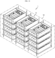
- FIG. 10 is a diagram illustrating an energy storage system according to an embodiment of the present disclosure.
- the energy storage system 1 may include at least one battery rack 10 of the previous embodiment and a rack container 50 accommodating the at least one battery rack 10.
- One or more battery racks 10 may be included. Hereinafter, this embodiment is described based on the plurality of battery racks 10.
- the plurality of battery racks 10 may include a combination of the battery racks 10 including the battery packs 100 used for the predetermined period of time or below the predetermined capacity and battery racks including the general battery packs.
- the rack container 50 may be configured to accommodate the plurality of battery racks 10, and may have an accommodation space in which the plurality of battery racks 10 is received.
- the energy storage system 1 may include the battery packs 100 (see FIG. 1 ) used for the predetermined period of time or below the predetermined capacity or the battery packs 100 used in electric vehicles or hybrid electric vehicles.
- the energy storage system 1 since the energy storage system 1 according to this embodiment includes the battery packs 100 used in vehicles that are usually discarded after wasted, it is possible to achieve cost savings associated with resource recycling and solve the environmental pollution problem caused by the wasted battery packs 100.
- the battery pack frame 200 for receiving the battery pack 100 for reuse after the use for the predetermined period of time or below the predetermined capacity more stably and ensuring safety when a fire occurs due to an abnormal situation such as overheat, and the battery rack 10 and the energy storage system 1 including the same.
Landscapes
- Chemical & Material Sciences (AREA)
- Chemical Kinetics & Catalysis (AREA)
- Electrochemistry (AREA)
- General Chemical & Material Sciences (AREA)
- Engineering & Computer Science (AREA)
- Manufacturing & Machinery (AREA)
- Health & Medical Sciences (AREA)
- Public Health (AREA)
- Business, Economics & Management (AREA)
- Emergency Management (AREA)
- Aviation & Aerospace Engineering (AREA)
- Battery Mounting, Suspending (AREA)
- Gas Exhaust Devices For Batteries (AREA)
- Connection Of Batteries Or Terminals (AREA)
Abstract
Description
- The present disclosure relates to a battery rack and san energy storage system comprising the same.
- The present application claims priority to
Korean Patent Application No. 10-2021-0093532 filed on July 16, 2021 - Due to their characteristics of being easily applicable to various products and electrical properties such as high energy density, secondary batteries are not only commonly applied to portable devices, but universally applied to electric vehicles (EVs) or hybrid electric vehicles (HEVs) that are driven by an electrical driving source. In addition to the primary advantage that it is possible to remarkably reduce the use of fossil fuels, secondary batteries do not produce by-products from the use of energy, so they are gaining attention as a new eco-friendly and energy efficient source of energy.
- The types of secondary batteries widely used at present include lithium ion batteries, lithium polymer batteries, nickel cadmium batteries, nickel hydrogen batteries, nickel zinc batteries or the like. A unit secondary battery cell or a unit battery cell has an operating voltage of about 2.5V to 4.5V. Accordingly, when a higher output voltage is required, a plurality of battery cells may be connected in series to form a battery pack. Additionally, the battery pack may be fabricated by connecting the plurality of battery cells in parallel according to the charge/discharge capacity required for the battery pack. Accordingly, the number of battery cells included in the battery pack may be variously set depending on the required output voltage or charge/discharge capacity.
- Meanwhile, when fabricating the battery pack by connecting the plurality of battery cells in series/in parallel, it is general to make a battery module including at least one battery cell, and then fabricate a battery pack or a battery rack using at least one battery module with an addition of any other component. Meanwhile, an energy storage system including at least one battery rack is constructed as an energy source.
- When the battery pack used in an electric vehicle is used for a predetermined period of time or below a predetermined capacity, in general, the battery pack is wasted due to the reduced driving performance of the vehicle. In general, the wasted battery pack includes cobalt oxide, lithium, manganese, nickel or the like, causing environmental pollution or dangers related to fires or electric shocks.
- About 70 to 80% of the wasted battery packs from electric vehicles may be reused in other applications than the fuel source of vehicles. In particular, the waste battery packs from electric vehicles may be reused in energy storage systems (ESSs). The waste battery packs from electric vehicles for reuse are referred to as reuse battery packs.
- Accordingly, there is a need for an approach to reuse the battery pack used for the predetermined period of time or below the predetermined capacity or the reuse battery pack more stably in the industrial applications such as energy storage systems. In particular, since the battery pack used for the predetermined period of time or below the predetermined capacity may have a higher fire risk caused by overheat, the design or fire prevention mechanism of a structure accommodating the battery pack, such as a battery pack frame, is emerging as the more important factor.
- The present disclosure is directed to providing a battery rack for receiving a battery pack for reuse after the use for a predetermined period of time or below a predetermined capacity more stably and ensuring safety when a fire occurs due to an abnormal situation such as overheat, and an energy storage system comprising the same.
- To solve the above-described problem, the present disclosure provides a battery rack including at least one battery pack used for a predetermined period of time or below a predetermined capacity; and a battery pack frame accommodating the at least one battery pack, and having a larger height than the at least one battery pack, wherein the at least one battery pack includes a service plug to open an inside of the at least one battery pack.
- A coolant may be injected into the battery pack frame such that a predetermined height of the at least one battery pack is submerged in the coolant when an abnormal situation occurs in the at least one battery pack.
- The service plug may open the inside of the at least one battery pack to guide the direct injection of the coolant into the at least one battery pack when an internal pressure of the at least one battery pack rises above a predetermined pressure in the event of the abnormal situation.
- The service plug may be disposed on an upper surface of the at least one battery pack.
- At least one feed pipe for feeding the coolant may be disposed above the battery pack frame.
- The at least one feed pipe may include at least one spring cooler to spray the coolant onto the at least one battery pack.
- The service plug may be disposed close to the at least one spring cooler.
- The battery pack frame may have at least on cable through-hole portion through which at least one cable for electrical connection to the at least one battery pack passes.
- At least one cable sealing member may be mounted in the at least one cable through-hole portion to prevent a leakage of the coolant.
- The battery pack may be a battery pack used in an electric vehicle or a hybrid electric vehicle.
- The battery rack may include a plurality of the battery packs, and the plurality of battery packs may be stacked on top of each other along a heightwise direction of the battery rack such that they are electrically connected to each other.
- Additionally, the present disclosure provides an energy storage system including at least one battery rack according to the above-described embodiments.
- According to the various embodiments as described above, it is possible to provide a battery rack for receiving a battery pack for reuse after the use for a predetermined period of time or below a predetermined capacity more stably and ensuring safety when a fire occurs due to an abnormal situation such as overheat, and an energy storage system comprising the same.
- The accompanying drawings illustrate an exemplary embodiment of the present disclosure and together with the following detailed description, serve to provide further understanding of the technical features of the present disclosure, and thus the present disclosure is not construed as being limited to the drawings.
-
FIG. 1 is a diagram illustrating a battery rack according to an embodiment of the present disclosure. -
FIG. 2 is a diagram illustrating a battery pack of the battery rack ofFIG. 1 . -
FIG. 3 is a diagram illustrating a battery pack frame of the battery rack ofFIG. 1 . -
FIG. 4 is a diagram illustrating a support frame according to another embodiment of the battery pack frame ofFIG. 3 . -
FIG. 5 is a diagram illustrating the main parts of the battery rack ofFIG. 1 . -
FIGS. 6 and7 are diagrams illustrating a coolant feed mechanism for preventing the spread of a fire in the event of an abnormal situation caused by overheat of the battery pack of the battery rack ofFIG. 1 . -
FIGS. 8 and9 are diagrams illustrating the mechanism for preventing the entry of coolant into an underlying battery pack below the battery pack in which an abnormal situation occurred when feeding the coolant inFIG. 7 . -
FIG. 10 is a diagram illustrating an energy storage system according to an embodiment of the present disclosure. - The present disclosure will become apparent by describing exemplary embodiments of the present disclosure in detail with reference to the accompanying drawings. The disclosed embodiments are provided by way of illustration to help the understanding of the present disclosure, and it should be understood that the present disclosure may be embodied in many other forms. Additionally, to help the understanding of the present disclosure, some elements in the accompanying drawings may be depicted on an exaggerated scale, not the actual scale.
-
FIG. 1 is a diagram illustrating a battery rack according to an embodiment of the present disclosure. - Referring to
FIG. 1 , thebattery rack 10 may include at least onebattery pack 100 and at least onebattery pack frame 200 accommodating the at least onebattery pack 100. Here, the at least onebattery pack 100 may include aservice plug 150 to open the at least onebattery pack 100 to guide the direct injection of a coolant into the at least onebattery pack 100 when the internal pressure of the at least onebattery pack 100 rises above a predetermined pressure in the event of an abnormal situation. Theservice plug 150 will be described in more detail below. - The at least one
battery pack 100 may be a battery pack used for a predetermined period of time or below a predetermined capacity. Specifically, the at least onebattery pack 100 may be a battery pack used in an electric vehicle or a hybrid electric vehicle. The at least one battery pack may be referred to as a reuse battery pack. - One or
more battery packs 100 may be included. Hereinafter, this embodiment is described based on the plurality ofbattery packs 100. - Hereinafter, the
battery pack 100 will be described in more detail. -
FIG. 2 is a diagram illustrating the battery pack of the battery rack ofFIG. 1 . - Referring to
FIG. 2 , thebattery pack 100 may include abattery cell 110, apack case 130 and theservice plug 150. - The
battery cell 110 may include a secondary battery, for example, a pouch type secondary battery, a prismatic secondary battery or a cylindrical secondary battery. Hereinafter, this embodiment is described by taking a secondary battery, to be exact, a pouch type secondary battery, as an example of thebattery cell 110. - One or
more battery cells 110 may be included. Hereinafter, this embodiment is described based on the plurality ofbattery cells 110 electrically connected to each other to form a battery cell assembly. - The
pack case 130 may accommodate the plurality ofbattery cells 110 and different types of electrical components and a cooling unit of thebattery pack 100. To this end, thepack case 130 may have an accommodation space in which the components of thebattery pack 100 are received. - The
service plug 150 is configured to disconnect the electrical connection of thebattery pack 100 by the user manipulation to prevent electric shock accidents in the operator's inspection or management of thebattery pack 100, and may be mounted in thepack case 130 and electrically connected to thebattery cells 110 or the electrical components of thebattery pack 100. - The
service plug 150 may open the at least onebattery pack 100 to guide the direct injection of the coolant into the at least onebattery pack 100 when the internal pressure of the at least onebattery pack 100 rises above the predetermined pressure in the event of the abnormal situation. - The
service plug 150 may be disposed on the upper surface of thebattery pack 100, i.e., on thepack case 130 to allow the user or the operator to easily manipulate. Furthermore, theservice plug 150 may be disposed close to the bottom of thefeed pipe 400 on the upper surface of thepack case 130 to smoothly inject the coolant into thebattery pack 100 in the event of the abnormal situation. Specifically, theservice plug 150 may be disposed close to at least one spring cooler 450 of thefeed pipe 400 as described below. - A
plug cover 155 may be disposed above theservice plug 150 to open theservice plug 150 to make the inside and outside of thepack case 130 of thebattery pack 100 communicate with each other when the internal pressure of thebattery pack 100 rises above the predetermined pressure. Theplug cover 155 may operate to open theservice plug 150 when the internal pressure of thebattery pack 100 rises above the predetermined pressure. The opening operation of theplug cover 155 may be performed by a passive or active method. For example, theplug cover 155 may be a rotatable structure or a valve structure which is opened at the predetermined pressure, or a rotatable structure or a valve structure which is connected to an electric controller of thebattery pack 100 to operate by the control of the electric controller at the predetermined pressure. This is provided for illustrative purpose, and the opening/closing structure of theplug cover 155 may use any other method of opening theservice plug 150 when the internal pressure of thebattery pack 100 is equal to or higher than the predetermined pressure. - The at least one
battery pack frame 200 may accommodate the at least onebattery pack 100 used for the predetermined period of time or below the predetermined capacity, and may have a larger height than the at least onebattery pack 100. - When the abnormal situation occurs due to overheat of the at least one
battery pack 100, the at least onebattery pack frame 200 may be filled with the coolant C such that a predetermined height of the at least onebattery pack 100 is submerged in the coolant C. - The at least one
battery pack frame 200 may receive the at least onebattery pack 100 used for the predetermined period of time or below the predetermined capacity more stably and control a dangerous situation such as a fire through the coolant C filled inside more quickly when the dangerous situation such as the fire occurs due to the abnormal situation caused by overheat of the at least onebattery pack 100. - A plurality of
battery pack frame 200 may be included, and the plurality of battery pack frames 200 may be stacked on top of each other along the heightwise direction of thebattery rack 10. - Hereinafter, the at least one
battery pack frame 200 will be described in more detail. -
FIG. 3 is a diagram illustrating the battery pack frame of the battery rack ofFIG. 1 . - Referring to
FIG. 3 , thebattery pack frame 200 may have an accommodation space which is exposed to top, and the at least onebattery pack 100 may be received in the accommodation space. - At least one feed pipe 400 (see
FIG. 5 ) for feeding the coolant C may be disposed above thebattery pack frame 200. The at least onefeed pipe 400 will be described in more detail below. - Additionally, at least one smoke detection sensor 500 (see
FIG. 5 ) may be disposed at the upper part of thebattery pack frame 200 to detect smoke when an abnormal situation occurs due to the overheat of the at least onebattery pack 100. The at least onesmoke detection sensor 500 will be described in more detail below. - Furthermore, the at least one smoke detection sensor 500 (see
FIG. 5 ) may be mounted at the upper part of thebattery pack frame 200, and asensor support 600 may be configured to support the at least onesmoke detection sensor 500. Thesensor support 600 will be described in more detail below. - The
battery pack frame 200 may include awater tank frame 210 and asupport frame 250. - The
water tank frame 210 may have an accommodation space which is exposed to top, for receiving the at least onebattery pack 100, and the accommodation space may be filled with the coolant C (seeFIG. 7 ). - The
water tank frame 210 may include at least one cable through-hole portion 212, at least onecable sealing member 214, a cooling inlet through-hole portion 215, a cooling outlet through-hole portion 216, aninlet sealing member 217 and anoutlet sealing member 218. - The at least one cable through-
hole portion 212 may be disposed on one side of thebattery pack frame 200, to be specific, one side of thewater tank frame 210, and may allow at least onecable 700 for electrical connection to the at least onebattery pack 100 to pass through. - The at least one
cable sealing member 214 is configured to prevent the leakage of the coolant C through the at least one cable through-hole portion 212, and may be mounted in the at least one cable through-hole portion 212. - The at least one
cable sealing member 214 may be mounted in the at least one cable through-hole portion 212. When thewater tank frame 210 is filled with the coolant C (seeFIG. 7 ), the at least onecable sealing member 214 may prevent the leakage of the coolant C from thewater tank frame 210 through the cable through-hole portion 212. - The cooling inlet through-
hole portion 215 may be disposed on one side of thebattery pack frame 200, to be specific, one side of thewater tank frame 210, and may allow acooling inlet 800 for cooling of thebattery pack 100 to pass through. - The cooling outlet through-
hole portion 216 may be disposed on one side of thebattery pack frame 200, to be specific, one side of thewater tank frame 210, and may allow acooling outlet 900 for cooling of thebattery pack 100 to pass through. - The
inlet sealing member 217 may be mounted in the cooling inlet through-hole portion 215. When thewater tank frame 210 is filled with the coolant C (seeFIG. 7 ), theinlet sealing member 217 may prevent the leakage of the coolant C from thewater tank frame 210 through the cooling inlet through-hole portion 215. - The
outlet sealing member 218 may be mounted in the cooling outlet through-hole portion 216. When thewater tank frame 210 is filled with the coolant C (seeFIG. 7 ), theoutlet sealing member 218 may prevent the leakage of the coolant C from thewater tank frame 210 through the cooling outlet through-hole portion 216. - The
support frame 250 may be disposed below thewater tank frame 210, and its edge may extend outward from the bottom edge of thewater tank frame 210. That is, thesupport frame 250 may have a wider area than the bottom area of thewater tank frame 210. - The
support frame 250 may ensure the strength of thebattery pack frame 200. Furthermore, thesupport frame 250 may prevent the entry of the coolant C into thewater tank frame 210 of the adjacentbattery pack frame 200 when the coolant C (seeFIG. 8 ) flows over thewater tank frame 210. -
FIG. 4 is a diagram illustrating a support frame according to another embodiment of the battery pack frame ofFIG. 3 . - Referring to
FIG. 4 , thebattery pack frame 205 may include awater tank frame 210 and asupport frame 255. - The
water tank frame 210 is substantially identical or similar to the previous embodiment, and an overlapping description is omitted. - The
support frame 255 may have astep portion 257 having a predetermined height at its edge to prevent the coolant C from flowing down when the coolant C (seeFIG. 9 ) leaks from thewater tank frame 210. - Through the
step portion 257, an additional coolant accommodation space may be formed at the edge of thesupport frame 255 to further hold the coolant C to the predetermined height. Furthermore, a drain pipe may be connected to one side of the additional coolant accommodation space at the edge of thesupport frame 255 to drain the coolant C. - Hereinafter, the other main components of the
battery rack 10 will be described in more detail. -
FIG. 5 is a diagram illustrating the main parts of the battery rack ofFIG. 1 . - Referring to
FIG. 5 , thebattery rack 10 may further include arack frame 300, thefeed pipe 400, thesmoke detection sensor 500, thesensor support 600, the at least onecable 700, the coolinginlet 800 and thecooling outlet 900. - The
rack frame 300 may support the plurality of battery pack frames 200 and guide the vertical stack of the plurality of battery pack frames 200. - A plurality of
feed pipes 400 may be included, and may be disposed above eachbattery pack frame 200. Thefeed pipes 400 may be connected to a coolant tank (not shown) outside of thebattery rack 10. - Each
feed pipe 400 may include at least one spring cooler 450 to spray the coolant C onto the at least onebattery pack 100. - The at least one spring cooler 450 may disposed above the
battery pack 100 above thebattery pack frame 200. One ormore spring coolers 450 may be included. Hereinafter, this embodiment is described based on the plurality ofspring coolers 450. - The
smoke detection sensor 500 may detect smoke coming out of thebattery pack 100 to detect a fire when the fire occurred due to overheat of thebattery pack 100. - The
smoke detection sensor 500 may be disposed above theservice plug 150 of thebattery pack 100 where smoke is highly likely to first come out of thebattery pack 100. - The
sensor support 600 is configured to support thesmoke detection sensor 500 more stably, and may have a bar shape having a predetermined length and may be mounted in thewater tank frame 210 of thebattery pack frame 200. - The at least one
cable 700 is used to connect the electrical components inside of thebattery pack 100 to an external electrical unit, and may be connected to thebattery pack 100. - The at least one
cable 700 may be connected to thebattery pack 100 in thewater tank frame 210 through the cable through-hole portion 212 of thewater tank frame 210 of thebattery pack frame 200. - The at least one
cable 700 may have a waterproof sealing coating on the outer surface to prevent an electrical short when thewater tank frame 210 is filled with the coolant C (seeFIG. 7 ). - The cooling
inlet 800 is used to cool thebattery pack 100, and may connect the external cooling unit to thebattery pack 100. The coolinginlet 800 may be connected to thebattery pack 100 in thewater tank frame 210 through the cooling inlet through-hole portion 215 of thewater tank frame 210. - The
cooling outlet 900 is used to cool thebattery pack 100, and may connect the external cooling unit to thebattery pack 100. Thecooling outlet 900 may be connected to thebattery pack 100 in thewater tank frame 210 through the cooling inlet through-hole portion 215 of thewater tank frame 210. - Hereinafter, the mechanism for preventing the spread of the fire in the event of the abnormal situation caused by overheat of the
battery pack 100 of thebattery rack 10 according to this embodiment will be described in more detail. -
FIGS. 6 and7 are diagrams illustrating the coolant feed mechanism for preventing the spread of the fire in the event of the abnormal situation caused by overheat of the battery pack of the battery rack ofFIG. 1 . - Referring to
FIGS. 6 and7 , in thebattery rack 10, the abnormal situation may occur in at least onespecific battery pack 100. Since thebattery pack 100 is thereuse battery pack 100 used for the predetermined period of time or below the predetermined capacity, the abnormal situation may occur due to overheat, causing a fire. - In this embodiment, when the fire occurs due to the abnormal situation caused by overheat of the
specific battery pack 100, for example, thetopmost battery pack 100 of thebattery rack 10, it is possible to put out the fire in thespecific battery pack 100 more quickly and prevent the spread of heat to theadjacent battery pack 100 more quickly. - Specifically, in the abnormal situation, when the
battery pack 100 is overheated and smoke or flames occur, thesmoke detection sensor 500 may detect the smoke, thereby detecting the abnormal situation quickly. When the smoke is detected by thesmoke detection sensor 500, the coolant C may be quickly sprayed onto thebattery pack 100 in which the abnormal situation occurred from thespring coolers 450 of thefeed pipe 400 above thebattery pack 100 in which the abnormal situation occurred. - In this instance, when the internal pressure of the
battery pack 100 rises above the predetermined pressure, theplug cover 155 of theservice plug 150 of thebattery pack 100 may be opened to make the inside and outside of thebattery pack 100 communicate with each other. - Accordingly, the coolant C sprayed from the
spring coolers 450 may be directly fed into thebattery pack 100 through the openedservice plug 150, thereby putting out the fire more quickly and preventing the spread of heat to theadjacent battery pack 100 more rapidly and quickly. - The spray of the coolant C through the
spring coolers 450 may continue until thebattery pack 100 is submerged in the coolant C in thewater tank frame 210 of thebattery pack frame 200 to completely put out the fire in thebattery pack 100. -
FIGS. 8 and9 are diagrams illustrating the mechanism for preventing the entry of the coolant into the underlying battery pack below the battery pack in which the abnormal situation occurred when feeding the coolant inFIG. 7 . - Referring to
FIG. 8 , during the spray of the coolant C through thespring coolers 450, the coolant C may flow over thewater tank frame 210 of thebattery pack frame 200. - In this embodiment, since the
support frame 250 of thebattery pack frame 200 extends outward from thewater tank frame 210, it is possible to prevent the coolant C from entering theadjacent battery pack 100, to be specific, theunderlying battery pack 100 when the coolant C flows over thewater tank frame 210. - Accordingly, in this embodiment, through the
support frame 250, it is possible to effectively prevent damage caused by the coolant C to theother battery pack 100 in which the fire did not occur. - Referring to
FIG. 9 , in case that thesupport frame 255 of thebattery pack frame 205 has thestep portion 257, the coolant C may be further held in the internal space formed by thestep portion 257 when the coolant C flows over thewater tank frame 210. - Accordingly, since the coolant C is further held in the internal space through the
step portion 257 to the predetermined height when the coolant C flows over thewater tank frame 210, it is possible to further delay the time when the overflowing coolant C pours down. Furthermore, it is possible to prevent the coolant C from flowing down more effectively by stopping the spray of the coolant C from thespring coolers 450 for the delayed time. - Here, an additional drain pipe may be connected to the internal space formed by the
step portion 257, and in this instance, the coolant C may exit through the additional drain pipe, so it is possible to prevent the entry of the coolant C into theunderlying battery pack 100 more effectively. -
FIG. 10 is a diagram illustrating an energy storage system according to an embodiment of the present disclosure. - Referring to
FIG. 10 , the energy storage system 1 may include at least onebattery rack 10 of the previous embodiment and arack container 50 accommodating the at least onebattery rack 10. - One or
more battery racks 10 may be included. Hereinafter, this embodiment is described based on the plurality of battery racks 10. - Furthermore, the plurality of
battery racks 10 may include a combination of the battery racks 10 including the battery packs 100 used for the predetermined period of time or below the predetermined capacity and battery racks including the general battery packs. - The
rack container 50 may be configured to accommodate the plurality ofbattery racks 10, and may have an accommodation space in which the plurality ofbattery racks 10 is received. - As described above, the energy storage system 1 according to this embodiment may include the battery packs 100 (see
FIG. 1 ) used for the predetermined period of time or below the predetermined capacity or the battery packs 100 used in electric vehicles or hybrid electric vehicles. - As described above, since the energy storage system 1 according to this embodiment includes the battery packs 100 used in vehicles that are usually discarded after wasted, it is possible to achieve cost savings associated with resource recycling and solve the environmental pollution problem caused by the wasted battery packs 100.
- According to the above-described various embodiments, it is possible to provide the
battery pack frame 200 for receiving thebattery pack 100 for reuse after the use for the predetermined period of time or below the predetermined capacity more stably and ensuring safety when a fire occurs due to an abnormal situation such as overheat, and thebattery rack 10 and the energy storage system 1 including the same. - While an exemplary embodiment of the present disclosure has been hereinabove illustrated and described, the present disclosure is not limited to the above-described particular embodiment and it is obvious to those skilled in the art that a variety of modifications and changes may be made thereto without departing from the claimed subject matter of the present disclosure in the appended claims, and such modifications and changes should not be individually understood from the technical aspects or features of the present disclosure.
Claims (12)
- A battery rack, comprising:at least one battery pack used for a predetermined period of time or below a predetermined capacity; anda battery pack frame accommodating the at least one battery pack, and having a larger height than the at least one battery pack,wherein the at least one battery pack includes a service plug to open an inside of the at least one battery pack.
- The battery rack according to claim 1, wherein a coolant is injected into the battery pack frame such that a predetermined height of the at least one battery pack is submerged in the coolant when an abnormal situation occurs in the at least one battery pack.
- The battery rack according to claim 2, wherein the service plug opens the inside of the at least one battery pack to guide direct injection of the coolant into the at least one battery pack when an internal pressure of the at least one battery pack rises above a predetermined pressure in the event of the abnormal situation.
- The battery rack according to claim 3, wherein the service plug is disposed on an upper surface of the at least one battery pack.
- The battery rack according to claim 3, wherein at least one feed pipe for feeding the coolant is disposed above the battery pack frame.
- The battery pack frame according to claim 5, wherein the at least one feed pipe includes at least one spring cooler to spray the coolant onto the at least one battery pack.
- The battery pack frame according to claim 6, wherein the service plug is disposed close to the at least one spring cooler.
- The battery rack according to claim 3, wherein the battery pack frame has at least on cable through-hole portion through which at least one cable for electrical connection to the at least one battery pack passes.
- The battery rack according to claim 8, wherein at least one cable sealing member is mounted in the at least one cable through-hole portion to prevent a leakage of the coolant.
- The battery rack according to claim 3, wherein the battery pack is a battery pack used in an electric vehicle or a hybrid electric vehicle.
- The battery rack according to claim 3, wherein comprises a plurality of the battery packs, and
wherein the plurality of battery packs is stacked on top of each other along a heightwise direction of the battery rack such that they are electrically connected to each other. - An energy storage system comprising at least one battery rack according to claim 1.
Applications Claiming Priority (2)
| Application Number | Priority Date | Filing Date | Title |
|---|---|---|---|
| KR1020210093532A KR102768467B1 (en) | 2021-07-16 | 2021-07-16 | Battery rack and energy storage system comprising the battery rack |
| PCT/KR2022/010320 WO2023287234A1 (en) | 2021-07-16 | 2022-07-14 | Battery rack and energy storage system comprising battery rack |
Publications (2)
| Publication Number | Publication Date |
|---|---|
| EP4303992A1 true EP4303992A1 (en) | 2024-01-10 |
| EP4303992A4 EP4303992A4 (en) | 2025-04-23 |
Family
ID=84920296
Family Applications (1)
| Application Number | Title | Priority Date | Filing Date |
|---|---|---|---|
| EP22842496.6A Pending EP4303992A4 (en) | 2021-07-16 | 2022-07-14 | BATTERY PACK AND ENERGY STORAGE SYSTEM COMPRISING SAME |
Country Status (6)
| Country | Link |
|---|---|
| US (1) | US20230369679A1 (en) |
| EP (1) | EP4303992A4 (en) |
| JP (1) | JP7617272B2 (en) |
| KR (1) | KR102768467B1 (en) |
| CN (1) | CN116235344A (en) |
| WO (1) | WO2023287234A1 (en) |
Families Citing this family (1)
| Publication number | Priority date | Publication date | Assignee | Title |
|---|---|---|---|---|
| WO2025089077A1 (en) * | 2023-10-25 | 2025-05-01 | パナソニックIpマネジメント株式会社 | Power supply device |
Family Cites Families (18)
| Publication number | Priority date | Publication date | Assignee | Title |
|---|---|---|---|---|
| WO2012165856A2 (en) * | 2011-05-31 | 2012-12-06 | 주식회사 엘지화학 | Unit rack for power storage, and power storage device comprising same |
| JP6037098B2 (en) * | 2012-02-06 | 2016-11-30 | 三菱自動車工業株式会社 | Battery pack water injection structure |
| CN103000841B (en) * | 2012-11-27 | 2016-05-18 | 芜湖市顺昌汽车配件有限公司 | A kind of combined battery cabinet |
| US9577230B2 (en) * | 2014-03-27 | 2017-02-21 | Ford Global Technologies, Llc | Integrated high voltage service disconnect for traction batteries |
| JP6279502B2 (en) * | 2015-03-13 | 2018-02-14 | 株式会社東芝 | Battery module |
| KR102002954B1 (en) * | 2015-11-30 | 2019-07-23 | 주식회사 엘지화학 | Battery pack and vehicle comprising the battery pack |
| KR101899000B1 (en) * | 2016-08-17 | 2018-09-14 | 주식회사 메가테크 | Rack System for Energy Storage System |
| CN107658512A (en) * | 2017-10-13 | 2018-02-02 | 重庆聚陆新能源有限公司 | Battery modules storage and the discharge and recharge box system of a kind of liquid feeding type fire-fighting |
| CN207303275U (en) * | 2017-10-13 | 2018-05-01 | 重庆聚陆新能源有限公司 | Battery modules storage and the discharge and recharge box system of a kind of liquid feeding type fire-fighting |
| EP3813179B1 (en) * | 2018-04-23 | 2025-03-05 | Panasonic Intellectual Property Management Co., Ltd. | Back-up power supply system and back-up battery rack for data center |
| TWI690350B (en) * | 2018-10-01 | 2020-04-11 | 協同能源科技股份有限公司 | System and method for battery fire extinguishing through flooding the battery |
| CN210331433U (en) * | 2019-03-22 | 2020-04-17 | 中国电力科学研究院有限公司 | An energy storage battery cluster with a fire-fighting structure |
| US20210077842A1 (en) * | 2019-09-17 | 2021-03-18 | Stem, Inc. | Sprinkler manifold for energy storage systems |
| PL4002551T3 (en) * | 2019-11-08 | 2025-03-17 | Lg Energy Solution, Ltd. | Battery rack and power storage device comprising same |
| JP2021091283A (en) * | 2019-12-10 | 2021-06-17 | 三菱自動車工業株式会社 | Battery pack |
| CN111029674A (en) * | 2019-12-27 | 2020-04-17 | 深圳安易控新能源科技有限公司 | Battery system capable of effectively preventing thermal runaway of lithium battery |
| KR102345323B1 (en) | 2020-01-20 | 2022-01-03 | 한국과학기술연구원 | Method for preparing cathode active material for high voltage sodium secondary battery |
| CN212725503U (en) * | 2020-08-07 | 2021-03-16 | 哲弗智能系统(上海)有限公司 | Protection frame, protection box and battery package |
-
2021
- 2021-07-16 KR KR1020210093532A patent/KR102768467B1/en active Active
-
2022
- 2022-07-14 JP JP2023530716A patent/JP7617272B2/en active Active
- 2022-07-14 US US18/029,884 patent/US20230369679A1/en active Pending
- 2022-07-14 CN CN202280006670.7A patent/CN116235344A/en active Pending
- 2022-07-14 WO PCT/KR2022/010320 patent/WO2023287234A1/en not_active Ceased
- 2022-07-14 EP EP22842496.6A patent/EP4303992A4/en active Pending
Also Published As
| Publication number | Publication date |
|---|---|
| US20230369679A1 (en) | 2023-11-16 |
| CN116235344A (en) | 2023-06-06 |
| EP4303992A4 (en) | 2025-04-23 |
| JP7617272B2 (en) | 2025-01-17 |
| KR20230012807A (en) | 2023-01-26 |
| WO2023287234A1 (en) | 2023-01-19 |
| KR102768467B1 (en) | 2025-02-13 |
| JP2023552097A (en) | 2023-12-14 |
Similar Documents
| Publication | Publication Date | Title |
|---|---|---|
| EP4195387A1 (en) | Battery pack frame, and battery rack and energy storage system comprising same | |
| US20230099554A1 (en) | Battery module having partition wall and thermal insulation layer for fire inhibition | |
| EP4002551B1 (en) | Battery rack and power storage device comprising same | |
| US12308467B2 (en) | Battery module including coolant jet spray nozzles with different melting point metal valves, and battery pack and vehicle including same | |
| US20140370336A1 (en) | Battery having a Protection from Adjacent Cells in Case of Discharge of a Battery Cell | |
| US20240213576A1 (en) | Battery module and battery pack comprising the same | |
| EP3993142B1 (en) | Battery rack and power storage apparatus comprising same | |
| US20230369679A1 (en) | Battery rack and energy storage system comprising same | |
| EP4175021B1 (en) | Battery pack and automobile including same | |
| JP7379720B2 (en) | Battery packs and automobiles containing them | |
| EP4250455A1 (en) | Battery rack and energy storage system comprising same | |
| KR102851131B1 (en) | Outside fire extinguishing apparatus of battery fire | |
| EP4618253A1 (en) | Battery pack having ignition delay structure | |
| EP4498475A1 (en) | Battery pack and device including same | |
| KR20250139997A (en) | Battery fire extinguishing system | |
| CN120898313A (en) | Battery module and battery pack including the battery module | |
| KR20260037923A (en) | A gasket for a battery pack, and a battery pack and a vehicle including the same |
Legal Events
| Date | Code | Title | Description |
|---|---|---|---|
| STAA | Information on the status of an ep patent application or granted ep patent |
Free format text: STATUS: THE INTERNATIONAL PUBLICATION HAS BEEN MADE |
|
| PUAI | Public reference made under article 153(3) epc to a published international application that has entered the european phase |
Free format text: ORIGINAL CODE: 0009012 |
|
| STAA | Information on the status of an ep patent application or granted ep patent |
Free format text: STATUS: REQUEST FOR EXAMINATION WAS MADE |
|
| 17P | Request for examination filed |
Effective date: 20231002 |
|
| AK | Designated contracting states |
Kind code of ref document: A1 Designated state(s): AL AT BE BG CH CY CZ DE DK EE ES FI FR GB GR HR HU IE IS IT LI LT LU LV MC MK MT NL NO PL PT RO RS SE SI SK SM TR |
|
| DAV | Request for validation of the european patent (deleted) | ||
| DAX | Request for extension of the european patent (deleted) | ||
| A4 | Supplementary search report drawn up and despatched |
Effective date: 20250321 |
|
| RIC1 | Information provided on ipc code assigned before grant |
Ipc: H01M 50/673 20210101ALI20250318BHEP Ipc: H01M 50/342 20210101ALI20250318BHEP Ipc: H01M 50/325 20210101ALI20250318BHEP Ipc: H01M 50/207 20210101ALI20250318BHEP Ipc: H01M 50/298 20210101ALI20250318BHEP Ipc: H01M 50/249 20210101ALI20250318BHEP Ipc: H01M 10/6568 20140101ALI20250318BHEP Ipc: H01M 10/625 20140101ALI20250318BHEP Ipc: A62C 35/58 20060101ALI20250318BHEP Ipc: A62C 99/00 20100101ALI20250318BHEP Ipc: A62C 3/16 20060101ALI20250318BHEP Ipc: H01M 10/48 20060101ALI20250318BHEP Ipc: H01M 10/613 20140101ALI20250318BHEP Ipc: H01M 10/627 20140101ALI20250318BHEP Ipc: H01M 10/6567 20140101ALI20250318BHEP Ipc: H01M 50/251 20210101AFI20250318BHEP |
|
| GRAP | Despatch of communication of intention to grant a patent |
Free format text: ORIGINAL CODE: EPIDOSNIGR1 |
|
| STAA | Information on the status of an ep patent application or granted ep patent |
Free format text: STATUS: GRANT OF PATENT IS INTENDED |
|
| INTG | Intention to grant announced |
Effective date: 20260113 |
|
| GRAS | Grant fee paid |
Free format text: ORIGINAL CODE: EPIDOSNIGR3 |