EP4303969A2 - Cartridge assembly - Google Patents
Cartridge assembly Download PDFInfo
- Publication number
- EP4303969A2 EP4303969A2 EP22203166.8A EP22203166A EP4303969A2 EP 4303969 A2 EP4303969 A2 EP 4303969A2 EP 22203166 A EP22203166 A EP 22203166A EP 4303969 A2 EP4303969 A2 EP 4303969A2
- Authority
- EP
- European Patent Office
- Prior art keywords
- area
- cartridge assembly
- cartridge
- boss
- downwards
- Prior art date
- Legal status (The legal status is an assumption and is not a legal conclusion. Google has not performed a legal analysis and makes no representation as to the accuracy of the status listed.)
- Pending
Links
Images


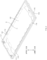

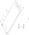


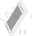


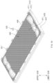


Classifications
-
- H—ELECTRICITY
- H01—ELECTRIC ELEMENTS
- H01M—PROCESSES OR MEANS, e.g. BATTERIES, FOR THE DIRECT CONVERSION OF CHEMICAL ENERGY INTO ELECTRICAL ENERGY
- H01M8/00—Fuel cells; Manufacture thereof
- H01M8/24—Grouping of fuel cells, e.g. stacking of fuel cells
- H01M8/2465—Details of groupings of fuel cells
- H01M8/247—Arrangements for tightening a stack, for accommodation of a stack in a tank or for assembling different tanks
- H01M8/2475—Enclosures, casings or containers of fuel cell stacks
-
- H—ELECTRICITY
- H01—ELECTRIC ELEMENTS
- H01M—PROCESSES OR MEANS, e.g. BATTERIES, FOR THE DIRECT CONVERSION OF CHEMICAL ENERGY INTO ELECTRICAL ENERGY
- H01M8/00—Fuel cells; Manufacture thereof
- H01M8/02—Details
- H01M8/0271—Sealing or supporting means around electrodes, matrices or membranes
- H01M8/0276—Sealing means characterised by their form
-
- H—ELECTRICITY
- H01—ELECTRIC ELEMENTS
- H01M—PROCESSES OR MEANS, e.g. BATTERIES, FOR THE DIRECT CONVERSION OF CHEMICAL ENERGY INTO ELECTRICAL ENERGY
- H01M8/00—Fuel cells; Manufacture thereof
- H01M8/02—Details
- H01M8/0271—Sealing or supporting means around electrodes, matrices or membranes
- H01M8/0273—Sealing or supporting means around electrodes, matrices or membranes with sealing or supporting means in the form of a frame
-
- H—ELECTRICITY
- H01—ELECTRIC ELEMENTS
- H01M—PROCESSES OR MEANS, e.g. BATTERIES, FOR THE DIRECT CONVERSION OF CHEMICAL ENERGY INTO ELECTRICAL ENERGY
- H01M8/00—Fuel cells; Manufacture thereof
- H01M8/24—Grouping of fuel cells, e.g. stacking of fuel cells
- H01M8/2404—Processes or apparatus for grouping fuel cells
-
- H—ELECTRICITY
- H01—ELECTRIC ELEMENTS
- H01M—PROCESSES OR MEANS, e.g. BATTERIES, FOR THE DIRECT CONVERSION OF CHEMICAL ENERGY INTO ELECTRICAL ENERGY
- H01M8/00—Fuel cells; Manufacture thereof
- H01M8/24—Grouping of fuel cells, e.g. stacking of fuel cells
- H01M8/241—Grouping of fuel cells, e.g. stacking of fuel cells with solid or matrix-supported electrolytes
- H01M8/242—Grouping of fuel cells, e.g. stacking of fuel cells with solid or matrix-supported electrolytes comprising framed electrodes or intermediary frame-like gaskets
-
- H—ELECTRICITY
- H01—ELECTRIC ELEMENTS
- H01M—PROCESSES OR MEANS, e.g. BATTERIES, FOR THE DIRECT CONVERSION OF CHEMICAL ENERGY INTO ELECTRICAL ENERGY
- H01M8/00—Fuel cells; Manufacture thereof
- H01M8/24—Grouping of fuel cells, e.g. stacking of fuel cells
- H01M8/2465—Details of groupings of fuel cells
-
- H—ELECTRICITY
- H01—ELECTRIC ELEMENTS
- H01M—PROCESSES OR MEANS, e.g. BATTERIES, FOR THE DIRECT CONVERSION OF CHEMICAL ENERGY INTO ELECTRICAL ENERGY
- H01M8/00—Fuel cells; Manufacture thereof
- H01M8/24—Grouping of fuel cells, e.g. stacking of fuel cells
- H01M8/2465—Details of groupings of fuel cells
- H01M8/247—Arrangements for tightening a stack, for accommodation of a stack in a tank or for assembling different tanks
- H01M8/248—Means for compression of the fuel cell stacks
-
- H—ELECTRICITY
- H01—ELECTRIC ELEMENTS
- H01M—PROCESSES OR MEANS, e.g. BATTERIES, FOR THE DIRECT CONVERSION OF CHEMICAL ENERGY INTO ELECTRICAL ENERGY
- H01M8/00—Fuel cells; Manufacture thereof
- H01M8/24—Grouping of fuel cells, e.g. stacking of fuel cells
- H01M8/2465—Details of groupings of fuel cells
- H01M8/2483—Details of groupings of fuel cells characterised by internal manifolds
-
- H—ELECTRICITY
- H01—ELECTRIC ELEMENTS
- H01M—PROCESSES OR MEANS, e.g. BATTERIES, FOR THE DIRECT CONVERSION OF CHEMICAL ENERGY INTO ELECTRICAL ENERGY
- H01M8/00—Fuel cells; Manufacture thereof
- H01M8/24—Grouping of fuel cells, e.g. stacking of fuel cells
- H01M8/249—Grouping of fuel cells, e.g. stacking of fuel cells comprising two or more groupings of fuel cells, e.g. modular assemblies
-
- Y—GENERAL TAGGING OF NEW TECHNOLOGICAL DEVELOPMENTS; GENERAL TAGGING OF CROSS-SECTIONAL TECHNOLOGIES SPANNING OVER SEVERAL SECTIONS OF THE IPC; TECHNICAL SUBJECTS COVERED BY FORMER USPC CROSS-REFERENCE ART COLLECTIONS [XRACs] AND DIGESTS
- Y02—TECHNOLOGIES OR APPLICATIONS FOR MITIGATION OR ADAPTATION AGAINST CLIMATE CHANGE
- Y02E—REDUCTION OF GREENHOUSE GAS [GHG] EMISSIONS, RELATED TO ENERGY GENERATION, TRANSMISSION OR DISTRIBUTION
- Y02E60/00—Enabling technologies; Technologies with a potential or indirect contribution to GHG emissions mitigation
- Y02E60/10—Energy storage using batteries
-
- Y—GENERAL TAGGING OF NEW TECHNOLOGICAL DEVELOPMENTS; GENERAL TAGGING OF CROSS-SECTIONAL TECHNOLOGIES SPANNING OVER SEVERAL SECTIONS OF THE IPC; TECHNICAL SUBJECTS COVERED BY FORMER USPC CROSS-REFERENCE ART COLLECTIONS [XRACs] AND DIGESTS
- Y02—TECHNOLOGIES OR APPLICATIONS FOR MITIGATION OR ADAPTATION AGAINST CLIMATE CHANGE
- Y02E—REDUCTION OF GREENHOUSE GAS [GHG] EMISSIONS, RELATED TO ENERGY GENERATION, TRANSMISSION OR DISTRIBUTION
- Y02E60/00—Enabling technologies; Technologies with a potential or indirect contribution to GHG emissions mitigation
- Y02E60/30—Hydrogen technology
- Y02E60/50—Fuel cells
Definitions
- the present disclosure relates to a cartridge assembly.
- a unit fuel cell includes a separator (an air electrode and a hydrogen electrode) and a membrane electrode assembly (MEA), and an interior of the unit cell is divided into three parts of a hydrogen part, an air part, and a cooling part.
- the fluids hydrogen, air, and cooling water may independently flow due to a mutually sealed structure.
- a fuel cell stack that may satisfy a target output is manufactured by repeatedly stacking and coupling a plurality of unit cells.
- the MEA may be exposed to an outside when the fuel cell stack is disassembled in a repair and maintenance process, and thus a performance of the stack may be degraded.
- buckling easily occurs in a process of stacking a plurality of unit cells, and an unbalance of the performance due to the buckling and a dissatisfaction of a sealing performance may occur.
- An aspect of the present disclosure provides a cartridge assembly, by which a stack may be easily repaired.
- Another aspect of the present disclosure provides a cartridge assembly that may secure a sealing state of unit cells before a stack is coupled.
- Another aspect of the present disclosure provides a cartridge assembly, by which cartridges may be easily aligned.
- a cartridge assembly includes a body part having an upper body opened upwards and downwards, and a lower body opened upwards and downwards, and coupled to the upper body to define an interior space, in which cells are stacked upwards and downwards, together with the upper body, and a cartridge including a cover part having an upper cover that covers an upper opening formed on an upper side of the upper body, and a lower cover that covers a lower opening formed on a lower side of the lower body, a plurality of cartridges are provided, and are stacked in an upward/downward direction, and each of the cartridges includes a connection part fixedly coupled to another cartridge disposed on an upper side or a lower side thereof to be adjacent thereto.
- connection part may include an upper boss area having a shape that protrudes upwards from the upper side of the upper body, and a lower boss area having a shape that protrudes downwards from the lower side of the lower body, the upper boss area may protrude from an upper surface of the upper body toward the upper opening, and the lower boss area may protrude from a lower surface of the lower body toward the lower opening.
- connection part may include a lower recess area formed at a location of the lower body and the lower cover, which corresponds to a location of the upper boss area, to be recessed, and into which the upper boss area is inserted, and an upper recess area formed at a location of the upper body and the upper cover, which corresponds to a location of the lower boss area, to be recessed, and into which the lower boss area is inserted.
- a plurality of upper boss areas and a plurality of upper recess areas may be formed, and may be alternately arranged along an upper periphery of the upper body.
- the upper body may be disposed to surround an upper side of a side surface of the lower body, and the body part may include a coupling recess formed to be recessed downwards from an upper side of the lower body, and a coupling boss member protruding inwards from a location of the upper body, which corresponds to the coupling recess, and inserted into the coupling recess.
- the body part may further include an alignment member protruding inwards from the lower body, and having a shape corresponding to an area, in which the cell is recessed.
- the alignment member may include a pair of extension parts having a shape extending upwards, and spaced apart from each other, an insertion recess formed between the pair of extension parts, and a first insertion part having a shape corresponding to an insertion recess of an alignment member of another cartridge disposed on a lower side thereof to be inserted into the insertion recess, and protruding downwards from a location corresponding to the insertion recess.
- the body part may further include a second insertion part protruding inwards from the upper side of the upper body, and having a shape corresponding to the insertion recess, the second insertion part may be disposed on a lower side of a first insertion part of another cartridge disposed on an upper side thereof, and an upward/downward length of the insertion recess may be larger than a sum of an upward/downward length of the second insertion part and an upward/downward length of the first insertion part.
- the body part may further include a lower fastening member protruding laterally from the lower body, and having a fastening hole passing therethrough upwards and downwards, at a middle portion thereof, and an upper fastening member protruding from the upper body, extending downwards, and that is snap-fitted with the fastening hole.
- connection part may include a bolt head protruding to the upper side of the upper body, and a bolt body extending downwards from the bolt head, and that is inserted into a bolt insertion hole passing through the upper body and the lower body, an area of the bolt head may be larger than an area of the bolt insertion hole, and an upward/downward length of the bolt insertion hole may be larger than an upward/downward length of the bolt body.
- the cartridge may further include a tension bar that surrounds a periphery of the body part, and the tension bar may include an upper contact part contacting an upper surface of the upper body, a lower contact part contacting a lower surface of the lower body, and an elastic part elastically connecting the upper contact part and the lower contact part.
- connection part may include a connection boss protruding upwards from the upper body, and a connection recess formed to have a shape corresponding to the connection boss, at a location of the lower body, which corresponds to the connection boss, the connection boss may be formed in an upper noncontact area that is an area of the upper body, which does not contact the upper contact part, and the connection recess may be formed in a lower noncontact area that is an area of the lower body, which does not contact the lower contact part.
- a through-hole may be formed on a side surface of each of the upper body and the lower body to pass therethrough in an upward/downward direction
- the connection part may include a snap-fit member passing through the through-hole upwards and snap-fitted with the through-hole
- the snap-fit member may include a protrusion area protruding upwards from the upper body
- connection part may further include an connection opening formed on a lower side of the snap-fit member, and opened downwards, and the connection opening may be configured such that a protrusion area of another cartridge disposed on a lower side thereof to be adjacent thereto is inserted thereinto.
- an upward/downward length of the connection opening may correspond to an upward/downward length of the protrusion area.
- an upward/downward length of the through-hole may be shorter than an upward/downward length of the snap-fit member.
- a cartridge assembly according to the present disclosure is a cartridge assembly, in which a plurality of cartridges including fuel cells in interiors thereof are assembled.
- Embodiments of the cartridge assembly according to the present disclosure include an interior space, in which cells may be stacked, in an interior thereof, and are commonly characterized in that they have a structure that may be aligned between adjacent cartridges.
- stacks may be manufactured by forming the cartridge assemblies in unit of cartridges, strength may be secured as compared with a case, in which only fuel cells are stacked to form a stack. Furthermore, because the fuel cells may not be exposed to an outside, degradation of performances of cells, which may occur due to exposure of a membrane electrode assembly (MEA) may be reduced.
- MEA membrane electrode assembly
- the cartridge assembly according to the first embodiment of the present disclosure is a cartridge assembly, in which cartridges that may accommodate fuel cells in interiors thereof are stacked and assembled.
- FIG. 1 is a view illustrating the cartridge assembly according to the first embodiment of the present disclosure.
- the cartridge assembly according to the first embodiment of the present disclosure may include a cartridge 100.
- FIG. 2 is a view illustrating the cartridge 100 of the cartridge assembly according to the first embodiment of the present disclosure.
- a plurality of cartridges 100 may be provided to be stacked along an upward/downward direction. That is, the cartridges 100 may be aligned and stacked upwards and downwards to form the cartridge assembly.
- the cartridge 100 may include a body part 110, a cover part 120, and a connection part 130.
- FIG. 3 is a view illustrating a state, in which an upper cover, which will be described below, is removed in FIG. 2 .
- FIG. 4 is a view illustrating the upper body of the cartridge assembly according to the first embodiment of the present disclosure.
- FIG. 5 is a view illustrating a lower body 112 and a lower cover 122 of the cartridge assembly according to the first embodiment of the present disclosure.
- the body part 110 may include an upper body 111 and the lower body 112.
- the upper body 111 may have a shape that is opened upwards and downwards.
- the lower body 112 may have a shape that is opened upwards and downwards.
- the lower body 112 may be coupled to the upper body 111 to define an interior space "S", in which cells “C” ( FIG. 8 ) may be stacked upwards and downwards, in an interior thereof, together with the upper body 111.
- the cells “C” may have a shape corresponding to a shape of the interior space "S”.
- the cells “C” may be fuel cells.
- five to ten cells may be stacked in the interior space "S", but the present disclosure is not limited thereto and the number of the cells that may be stacked may be changed according to a necessity of a user.
- the upper body 111 may be disposed to surround an upper side of a side surface of the lower body 112. This may mean that the upper body 111 has a shape that surrounds the lower body 112 from a lateral side.
- a coupling recess 113 that is recessed downwards may be formed on an upper side of the lower body 112.
- a plurality of coupling recesses 113 may be formed along an upper periphery of the lower body 112.
- a coupling boss member 114 may be formed in the upper body 111.
- the coupling boss member 114 may protrude inwards from a location of an inner surface of the upper body 111, which corresponds to the coupling recess 113 formed in the lower body 112.
- the coupling boss member 114 may be configured to be inserted into the coupling recess 113. As the coupling boss member 114 is inserted into the coupling recess 113, the upper body 111 and the lower body 112 may be engaged with each other in the cartridge 100.
- the upper body 111 and the lower body 112 may be pressed and attached to each other along an upward/downward direction. They may maintain a state, in which they are not pressed and attached to each other upwards and downwards, to stably dispose the cells, before the cells are not completely disposed in the interior space. Thereafter, after the cells are completely disposed in the interior space, a distance between the upper body 111 and the lower body 112 may be reduced by pressing and attaching them. Accordingly, a sealing performance of the cartridge that keeps the cells may be enhanced.
- the body part 110 may include a lower fastening member 115 and an upper fastening member 116.
- the lower fastening member 115 may protrude laterally from the lower body 112, and a fastening hole 115' that passes therethrough upwards and downwards may be formed at a middle portion of the lower fastening member 115.
- the upper fastening member 116 may protrude from the upper body 111, may extend downwards, and may be snap-fitted with the fastening hole 115'. That is, the upper fastening member 116 may be restrained from being moved upwards when a portion of the upper fastening member 116 passes through the fastening hole 115' after approaching toward the fastening hole 115' from a top.
- the upper fastening member is elastic, it may be restrained from being moved upwards after passing through the fastening hole 115' and returning to an original shape, the upper fastening member may have a retractable boss, and it may be elastically supported as the boss proceeds and retracts.
- the upper fastening member 116 may approach the lower fastening member 115 at the same time when the upper body 111 and the lower body 112 are pressed and attached to each other.
- the upper fastening member 116 and the lower fastening member 115 may function to maintain the pressing and attaching of the upper body 111 and the lower body 112.
- the number of the lower fastening members 115 and the number of the upper fastening members 116 may correspond to each other. As an example, as illustrated in FIG. 2 , four lower fastening members 115 and four upper fastening members 116 may be formed.
- the cover part 120 may function to maintain a sealing state of the cells located in the interior space "S" and perform a function for electrical conduction.
- the cover part 120 may include an upper cover 121 and the lower cover 122.
- the upper cover 121 may cover an upper opening.
- the upper opening may be formed on an upper side of the upper body 111.
- An upper hole may be formed in the upper cover 121.
- a path, along which air and hydrogen are supplied to the fuel cell, may be secured through the upper hole, and a path, along which water is discharged after a reaction, may be secured.
- the lower cover 122 may cover an lower opening.
- the lower opening may be formed on a lower side of the lower body 112.
- a lower hole may be formed in the lower cover 122.
- the lower hole may perform the same function as that of the upper hole.
- FIG. 6 is a view illustrating the connection part in a state before two cartridges disposed upwards and downwards are connected to each other.
- FIG. 7 is a view illustrating the connection part in a state after the two cartridges disposed upwards and downwards are connected to each other.
- the connection part 130 may be a configuration for coupling the cartridge 100 and another cartridge 100' disposed on an upper side or a lower side to be adjacent thereto.
- connection part 130 may have various shapes. That is, the connection part 130 only has to be a configuration for fixedly coupling any one cartridge 100 to anther cartridge 100' disposed on an upper side or a lower side to be adjacent thereto, and it is not always necessary for the body part 110 and the cover part 120 to be separate parts. That is, the connection part 130 may be a portion of the body part 110 or the cover part 120.
- connection part 130 of the cartridge assembly according to the first embodiment will be described in detail.
- the connection part 130 may include an upper boss area 131 and a lower boss area 132.
- the upper boss area 131 may have a shape that protrudes upwards from an upper side of the upper body 111. Furthermore, the upper boss area 131 may protrude from the upper side of the upper body 111 toward the upper opening. This may mean that a portion of the upper boss area 131 is located on an upper side of the upper cover 121. Because a portion of the upper boss area 131 is located on an upper side of the upper cover 121, the upper cover 121 may be prevented from deviating upwards.
- the lower boss areas 132 and 132' may have a shape that protrudes downwards from a lower side of the lower body 112. Furthermore, the lower boss areas 132 and 132' may protrude from the lower side of the lower body 112 toward the lower opening. This may mean that a portion of the lower boss area 132 and 132' is located on a lower side of the lower cover 122. Because a portion of the lower boss area 132 and 132' is located on the lower side of the lower cover 122, the lower cover 122 may be prevented from deviating downwards.
- the upper boss area 131 may be integrally formed with the upper body 111
- the lower boss area 132 may be integrally formed with the lower body 112.
- the connection part 130 may include lower recess areas 133 and 133' and an upper recess area 134.
- the lower recess areas 133 and 133' may be formed at locations of the lower body 112 and the lower cover 122 corresponding to the upper boss area 131 to be recessed.
- the upper boss area 131 may be inserted into the lower recess area 133' of any one cartridge 100'.
- the upper boss area 131 may be the upper boss area 131 of the cartridge 100 located on a lower side of any one cartridge 100' to be adjacent thereto.
- the upper recess area 134 may be formed at a location of the upper body 111 and the upper cover 121 corresponding to the lower boss area 132 to be recessed. With reference to FIGS. 6 and 7 , the lower boss area 132' may be inserted into the upper recess area 134.
- the lower boss area 132' as illustrated in FIGS. 6 and 7 , may be the lower boss area 132' of another cartridge 100' located on an upper side to be adjacent.
- a plurality of upper boss areas 131 and a plurality of upper recess areas 134 may be formed. Furthermore, the upper boss areas 131 and the upper recess areas 134 may be alternately arranged along an upper periphery of the upper body 111.
- a plurality of lower boss areas 132 and a plurality of lower recess areas 133 may be formed. Furthermore, the lower boss areas 132 and the lower recess areas 133 may be alternately arranged along a lower periphery of the lower body 112.
- FIG. 8 is a view illustrating the alignment member and the cells, viewed from a top.
- the body part 110 may further include the alignment member 117.
- the alignment member 117 may protrude inwards from the lower body 112, and may have a shape corresponding to an area, in which the cells "C" are recessed laterally. For example, when it is assumed that front left and right corners of the cell has an inwardly recessed shape, the alignment member 117 may protrude in a shape corresponding to the recessed area.
- the alignment member 117 may have a structure for aligning and stacking the cells "C" in the interior space "S".
- FIG. 8 illustrates a state, in which the cells "C" are aligned by the alignment member 117.
- three alignment members 117 may be formed, but the present disclosure is not limited thereto and the number thereof may be different according to the shape of the cells "C". As illustrated in FIG. 3 , two alignment members may be provided at corners of a lateral circumference of the lower body 112, respectively, and the remaining alignment member may be provided at a location that is spaced apart from the corners of the lateral circumference of the lower body 112.
- FIG. 9 is a view illustrating the alignment member and a second insertion part positioned in a state before the upper body and the lower body are pressed and attached.
- FIG. 10 is a view illustrating a state before the alignment members of two cartridges disposed upwards and downwards are connected to each other.
- FIG. 11 is a view illustrating a state after the alignment members of the two cartridges disposed upwards and downwards are connected to each other.
- the alignment member 117 may include an extension part 117a, an insertion recess 117b, and a first insertion part 117c.
- the extension part 117a may have a shape that extends upwards.
- a pair of extension parts 117a may be provided to be spaced horizontally apart from each other.
- the insertion recess 117b may be formed between the pair of spaced extension parts 117a.
- the first insertion part 117c may have a structure that is to be inserted into the insertion recess 117b of the alignment member 117 of another cartridge 100 disposed on a lower side thereof to be adjacent thereto.
- the first insertion part 117c may have a shape corresponding to the insertion recess 117b, and may protrude downwards from a location corresponding to the insertion recess 117b.
- the alignment members 117 may have a shape that is similar to a Y shape.
- the body part 110 may further include a second insertion part 118.
- the second insertion part 118 may be a part that protrudes inwards from an upper side of the upper body 111 and corresponds to the insertion recess 117b.
- the second insertion part 118 may be disposed on a lower side of a first insertion part 117c' of another cartridge 100' disposed on an upper side thereof. That is, the first insertion part 117c' of the other cartridge 100' disposed on the upper side may be positioned on an upper side of the second insertion part 118 after the second insertion part 118 is inserted into the insertion recess 117b.
- an upward/downward length of the insertion recess 117b may be made to be larger than sum of an upward/downward length of the second insertion part 118 and an upward/downward length of the first insertion part 117c.
- the upper boss area 131 of the cartridge 100 of the cartridge assembly according to the first embodiment of the present disclosure is inserted into the lower recess area 133' ( FIG. 6 ) of another cartridge 100' disposed on an upper side thereof to be adjacent thereto, whereas the first insertion part 117c' of another cartridge 100' disposed on an upper side thereof to be adjacent thereto is inserted into the insertion recess 117b of the alignment member 117. Then, the lower boss area 132' of the other cartridge 100' disposed on the upper side thereof to be adjacent thereto may be inserted into the upper recess area 134.
- the lower boss area 132 of the cartridge 100 of the cartridge assembly according to the first embodiment of the present disclosure is inserted into the upper recess areas of another cartridge disposed on a lower side thereof to be adjacent thereto, whereas the first insertion part 117c of the alignment member 117 is inserted into the insertion recess of the alignment member of another cartridge disposed on a lower side to be adjacent thereto.
- FIG. 12 is a conceptual view illustrating a cartridge assembly according to a second embodiment of the present disclosure.
- FIG. 13 is a view illustrating a cartridge of the cartridge assembly according to the second embodiment of the present disclosure.
- the cartridge assembly according to the second embodiment of the present disclosure will be described in detail with reference to FIGS. 12 to 13 .
- FIG. 13 a state, in which the upper and lower sides are reversed, is illustrated for helping understandings.
- the cartridge assembly according to the second embodiment is different from the cartridge assembly according to the first embodiment particularly in that a shape of a connection part 230 has a bolt shape.
- the same or corresponding reference numerals are given to configurations that are the same as or correspond to those of the cartridge assembly according to the first embodiment, and a detailed description thereof will be omitted.
- the connection part 230 may have a bolt structure.
- the connection part 230 may include a bolt head 231 and a bolt body 232.
- the bolt head 231 may protrude to an upper side of an upper body 211.
- the bolt body 232 may extend downwards from the bolt head 231.
- a body part 210 may include a bolt insertion hole 213.
- the bolt insertion hole 213 may be a hole that passes through the upper body 211 and a lower body 212.
- the bolt body 232 may be inserted into the bolt insertion hole 213.
- An area of the bolt head 231 may be larger than that of the bolt insertion hole 213. Because the area of the bolt head 231 is larger than that of the bolt insertion hole 213, the bolt head 231 may be prevented from being inserted into the bolt insertion hole 213.
- An upward/downward length of the bolt insertion hole 213 may be larger than that of the bolt body 232. Because the upward/downward length of the bolt insertion hole 213 is larger than that of the bolt body 232, a lower portion of the bolt insertion hole 213 may be left as an empty space. A bolt head of another cartridge disposed on a lower side to be adjacent thereto may be inserted into the empty space of the bolt insertion hole 213. Though the structure, the cartridges 200 according to the second embodiment may be stacked to constitute the cartridge assembly according to the second embodiment.
- FIG. 14 is a conceptual view illustrating a cartridge assembly according to a third embodiment of the present disclosure.
- FIG. 15 is a view illustrating a cartridge of the cartridge assembly according to the third embodiment of the present disclosure.
- FIG. 16 is a view illustrating a state, in which an upper cover and a lower cover are removed from the cartridge of the cartridge assembly according to the third embodiment of the present disclosure.
- the cartridge assembly according to the third embodiment of the present disclosure will be described in detail with reference to FIGS. 14 to 16 .
- FIG. 15 a state, in which the upper and lower sides are reversed, is illustrated for helping understandings.
- the cartridge assembly according to the third embodiment is different from the cartridge assembly according to the first embodiment particularly in a shape of a connection part 330 and presence of a tension bar 340.
- the same or corresponding reference numerals are given to configurations that are the same as or correspond to those of the cartridge assembly according to the first embodiment, and a detailed description thereof will be omitted.
- the cartridge of the cartridge assembly according to the third embodiment of the present disclosure may include the tension bar 340.
- the tension bar 340 may be configured to surround a periphery of a body part 310.
- the tension bar 340 may be a member that maintains pressing and attaching of an upper body 311 and a lower body 312 of the body part 310.
- the tension bar 340 may include an upper contact part 341, a lower contact part 342, and an elastic part 343.
- the upper contact part 341 may be a part that contacts an upper surface of the upper body 311.
- the lower contact part 342 may be a part that contacts a lower surface of the lower body 312.
- the elastic part 343 may elastically connect the upper contact part 341 and the lower contact part 342. Due to the elasticity of the elastic part 343, the pressing and attaching of the upper body 311 and the lower body 312 may be maintained.
- a cross-sectional shape of the tension bar 340 when the tension bar 340 is cut vertically may be similar to a shape obtained by rotating a 'U' shape by 90 degrees.
- connection part 330 may include a connection boss 331 and a connection recess 332.
- the connection boss 331 may protrude upwards from the upper body 311.
- the connection recess 332 may be formed at a location of the lower body 312, which corresponds to the connection boss 331, to have a shape corresponding to the connection boss 331. This may mean that a connection boss of another cartridge disposed on a lower side to be adjacent thereto may be inserted into the connection recess 332 of a cartridge 300.
- the cartridges 300 according to the third embodiment may be stacked to constitute the cartridge assembly according to the third embodiment.
- connection boss 331 may be formed by an upper noncontact area.
- the upper noncontact area may mean an area of the upper body 311, which does not contact the upper contact part 341.
- the connection recess 332 may be formed by a lower noncontact area.
- the lower noncontact area may mean an area of the lower body 312, which does not contact the lower contact part 342.
- FIG. 17 is a conceptual view illustrating a cartridge assembly according to a fourth embodiment of the present disclosure.
- FIG. 18 is a view illustrating a cartridge of the cartridge assembly according to the fourth embodiment of the present disclosure.
- FIG. 19 is a view obtained by reversing FIG. 18 upwards and downwards.
- FIG. 20 is a view of a state, in which a connection part is removed in FIG. 18 .
- FIG. 21 is a view illustrating the connection part of the cartridge assembly according to the fourth embodiment of the present disclosure.
- FIG. 22 is a view obtained by reversing FIG. 21 upwards and downwards.
- the cartridge assembly according to the fourth embodiment is different from the cartridge assembly according to the first embodiment particularly in a shape of a connection part 430.
- the same or corresponding reference numerals are given to configurations that are the same as or correspond to those of the cartridge assembly according to the first embodiment, and a detailed description thereof will be omitted.
- a body part 410 may include a through-hole 413.
- the through-hole 413 may pass through side surfaces of an upper body 411 and a lower body 412 in an upward/downward direction.
- the through-hole 413 may have a slot shape when viewed from a top, and this is merely an example and the through-hole 413 may have various shapes.
- a plurality of through-holes 413 may be formed.
- the through-hole 413 may be formed to pass through a cover part 420.
- the cover part 420 may include a portion that overlaps the body part 410, and the through-hole 413 may be formed at the portion, at which the body part 410 and the cover part 420 overlap each other.
- an upper cover 421 may be formed such that opposite ends thereof are stepped downwards.
- Support members 440 that are to be disposed to correspond to a height of the upper cover 421 may be disposed on an upper side of opposite ends of the upper cover 421.
- the through-hole 413 may be formed to pass through the support members 440.
- a lower cover 422 may be formed such that opposite ends thereof are stepped upwards.
- Connection parts 430 may be disposed on a lower side of opposite ends of the lower cover 422.
- the connection part 430 may include a snap-fit member 431.
- the snap-fit member 431 may be snap-fitted while passing through the through-hole 413 upwards.
- an upper end of the snap-fit member 431 may be restrained from being moved downwards as it is pressed by the upper body 411 and the lower body 412 that define the through-hole 413 before passing through the through-hole 413, is restored by a restoring force after it passes through the through-hole 413, and protrude to an outside of the through-hole 413.
- the number of the snap-fit members 431 may correspond to the number of the through-holes 413.
- the snap-fit member 431 may include a protrusion area 431'.
- the protrusion area 431' may be an area that protrudes to an upper side of the upper body 411.
- the protrusion area 431' may be configured to be inserted into a through-hole 413 of another cartridge disposed on an upper side thereof to be adjacent thereto.
- an upward/downward length of the through-hole 413 may be smaller than that of the snap-fit member 431. Because the upward/downward length of the through-hole 413 is smaller than that of the snap-fit member 431, the protrusion area 431' may be formed. As an example, the upward/downward length of the through-hole 413 may correspond to a value obtained by subtracting an upward/downward length of the protrusion area 431' from the upward/downward length of the snap-fit member 431.
- connection part 430 may include a connection opening 432 that is disposed on a lower side of the snap-fit member 431 and is opened downwards.
- a protrusion area of another cartridge disposed on a lower side to be adjacent thereto may be inserted into the connection opening 432.
- the upward/downward length of the connection opening 432 may correspond to the upward/downward length of the protrusion area 431'.
- cartridges 400 according to the fourth embodiment may be stacked to constitute the cartridge assembly according to the fourth embodiment.
- the cartridges may be replaced and inspected independently, and thus it may become easy to repair the stacks and it may be possible to secure a sealing state of the cells even before the stacks are coupled.
- connection part that aligns and connects the cartridges is provided, it may become easy to stack the cartridges and decrease buckling.
Landscapes
- Life Sciences & Earth Sciences (AREA)
- Engineering & Computer Science (AREA)
- Manufacturing & Machinery (AREA)
- Sustainable Development (AREA)
- Sustainable Energy (AREA)
- Chemical & Material Sciences (AREA)
- Chemical Kinetics & Catalysis (AREA)
- Electrochemistry (AREA)
- General Chemical & Material Sciences (AREA)
- Stackable Containers (AREA)
- Fuel Cell (AREA)
Abstract
Description
- This application claims the benefit of priority to
Korean Patent Application No. 10-2022-0083386, filed in the Korean Intellectual Property Office on July 6, 2022 - The present disclosure relates to a cartridge assembly.
- A unit fuel cell includes a separator (an air electrode and a hydrogen electrode) and a membrane electrode assembly (MEA), and an interior of the unit cell is divided into three parts of a hydrogen part, an air part, and a cooling part. The fluids (hydrogen, air, and cooling water) may independently flow due to a mutually sealed structure.
- Meanwhile, because a target output cannot be achieved only with a unit cell, a fuel cell stack that may satisfy a target output is manufactured by repeatedly stacking and coupling a plurality of unit cells.
- It is troublesome to repair a conventional fuel cell stack, and thus there is an inconvenience of having to disassemble an entire stack to replace specific cells. Furthermore, in the process, the separator may be deformed or the MEA may be damaged so that its function may be lost or costs may be increased. Furthermore, because a stack has to be replaced in a special environment, it may be rather reasonable to replace the entire stack.
- Furthermore, because it is impossible to secure a sealing state of the unit cells before the conventional fuel cell stack is coupled, the MEA may be exposed to an outside when the fuel cell stack is disassembled in a repair and maintenance process, and thus a performance of the stack may be degraded.
- Furthermore, according to the conventional fuel cell stack, buckling easily occurs in a process of stacking a plurality of unit cells, and an unbalance of the performance due to the buckling and a dissatisfaction of a sealing performance may occur.
- The present disclosure has been made to solve the above-mentioned problems occurring in the prior art while advantages achieved by the prior art are maintained intact.
- An aspect of the present disclosure provides a cartridge assembly, by which a stack may be easily repaired.
- Another aspect of the present disclosure provides a cartridge assembly that may secure a sealing state of unit cells before a stack is coupled.
- Another aspect of the present disclosure provides a cartridge assembly, by which cartridges may be easily aligned.
- The technical problems to be solved by the present disclosure are not limited to the aforementioned problems, and any other technical problems not mentioned herein will be clearly understood from the following description by those skilled in the art to which the present disclosure pertains.
- According to an aspect of the present disclosure, a cartridge assembly includes a body part having an upper body opened upwards and downwards, and a lower body opened upwards and downwards, and coupled to the upper body to define an interior space, in which cells are stacked upwards and downwards, together with the upper body, and a cartridge including a cover part having an upper cover that covers an upper opening formed on an upper side of the upper body, and a lower cover that covers a lower opening formed on a lower side of the lower body, a plurality of cartridges are provided, and are stacked in an upward/downward direction, and each of the cartridges includes a connection part fixedly coupled to another cartridge disposed on an upper side or a lower side thereof to be adjacent thereto.
- In another example, the connection part may include an upper boss area having a shape that protrudes upwards from the upper side of the upper body, and a lower boss area having a shape that protrudes downwards from the lower side of the lower body, the upper boss area may protrude from an upper surface of the upper body toward the upper opening, and the lower boss area may protrude from a lower surface of the lower body toward the lower opening.
- In another example, the connection part may include a lower recess area formed at a location of the lower body and the lower cover, which corresponds to a location of the upper boss area, to be recessed, and into which the upper boss area is inserted, and an upper recess area formed at a location of the upper body and the upper cover, which corresponds to a location of the lower boss area, to be recessed, and into which the lower boss area is inserted.
- In another example, a plurality of upper boss areas and a plurality of upper recess areas may be formed, and may be alternately arranged along an upper periphery of the upper body.
- In another example, the upper body may be disposed to surround an upper side of a side surface of the lower body, and the body part may include a coupling recess formed to be recessed downwards from an upper side of the lower body, and a coupling boss member protruding inwards from a location of the upper body, which corresponds to the coupling recess, and inserted into the coupling recess.
- In another example, the body part may further include an alignment member protruding inwards from the lower body, and having a shape corresponding to an area, in which the cell is recessed.
- In another example, the alignment member may include a pair of extension parts having a shape extending upwards, and spaced apart from each other, an insertion recess formed between the pair of extension parts, and a first insertion part having a shape corresponding to an insertion recess of an alignment member of another cartridge disposed on a lower side thereof to be inserted into the insertion recess, and protruding downwards from a location corresponding to the insertion recess.
- In another example, the body part may further include a second insertion part protruding inwards from the upper side of the upper body, and having a shape corresponding to the insertion recess, the second insertion part may be disposed on a lower side of a first insertion part of another cartridge disposed on an upper side thereof, and an upward/downward length of the insertion recess may be larger than a sum of an upward/downward length of the second insertion part and an upward/downward length of the first insertion part.
- In another example, the body part may further include a lower fastening member protruding laterally from the lower body, and having a fastening hole passing therethrough upwards and downwards, at a middle portion thereof, and an upper fastening member protruding from the upper body, extending downwards, and that is snap-fitted with the fastening hole.
- In another example, the connection part may include a bolt head protruding to the upper side of the upper body, and a bolt body extending downwards from the bolt head, and that is inserted into a bolt insertion hole passing through the upper body and the lower body, an area of the bolt head may be larger than an area of the bolt insertion hole, and an upward/downward length of the bolt insertion hole may be larger than an upward/downward length of the bolt body.
- In another example, the cartridge may further include a tension bar that surrounds a periphery of the body part, and the tension bar may include an upper contact part contacting an upper surface of the upper body, a lower contact part contacting a lower surface of the lower body, and an elastic part elastically connecting the upper contact part and the lower contact part.
- In another example, the connection part may include a connection boss protruding upwards from the upper body, and a connection recess formed to have a shape corresponding to the connection boss, at a location of the lower body, which corresponds to the connection boss, the connection boss may be formed in an upper noncontact area that is an area of the upper body, which does not contact the upper contact part, and the connection recess may be formed in a lower noncontact area that is an area of the lower body, which does not contact the lower contact part.
- In another example, a through-hole may be formed on a side surface of each of the upper body and the lower body to pass therethrough in an upward/downward direction, the connection part may include a snap-fit member passing through the through-hole upwards and snap-fitted with the through-hole, and the snap-fit member may include a protrusion area protruding upwards from the upper body.
- In another example, the connection part may further include an connection opening formed on a lower side of the snap-fit member, and opened downwards, and the connection opening may be configured such that a protrusion area of another cartridge disposed on a lower side thereof to be adjacent thereto is inserted thereinto.
- In another example, an upward/downward length of the connection opening may correspond to an upward/downward length of the protrusion area.
- In another example, an upward/downward length of the through-hole may be shorter than an upward/downward length of the snap-fit member.
- The above and other objects, features and advantages of the present disclosure will be more apparent from the following detailed description taken in conjunction with the accompanying drawings:
-
FIG. 1 is a view illustrating a cartridge assembly according to a first embodiment of the present disclosure; -
FIG. 2 is a view illustrating a cartridge of a cartridge assembly according to a first embodiment of the present disclosure; -
FIG. 3 is a view illustrating a state, in which an upper cover is removed inFIG. 2 ; -
FIG. 4 is a view illustrating an upper body of a cartridge assembly according to a first embodiment of the present disclosure; -
FIG. 5 is a view illustrating a lower body and a lower cover of a cartridge assembly according to a first embodiment of the present disclosure; -
FIG. 6 is a view illustrating a connection part in a state before two cartridges disposed upwards and downwards are connected to each other; -
FIG. 7 is a view illustrating a connection part in a state after two cartridges disposed upwards and downwards are connected to each other; -
FIG. 8 is a view illustrating an alignment member and cells, viewed from a top; -
FIG. 9 is a view illustrating an alignment member and a second insertion part positioned in a state before an upper body and a lower body are pressed and attached; -
FIG. 10 is a view illustrating a state before alignment members of two cartridges disposed upwards and downwards are connected to each other; -
FIG. 11 is a view illustrating a state after alignment members of two cartridges disposed upwards and downwards are connected to each other; -
FIG. 12 is a conceptual view illustrating a cartridge assembly according to a second embodiment of the present disclosure; -
FIG. 13 is a view illustrating a cartridge of a cartridge assembly according to a second embodiment of the present disclosure; -
FIG. 14 is a conceptual view illustrating a cartridge assembly according to a third embodiment of the present disclosure; -
FIG. 15 is a view illustrating a cartridge of a cartridge assembly according to a third embodiment of the present disclosure; -
FIG. 16 is a view illustrating a state, in which an upper cover and a lower cover are removed from a cartridge of a cartridge assembly according to a third embodiment of the present disclosure; -
FIG. 17 is a conceptual view illustrating a cartridge assembly according to a fourth embodiment of the present disclosure; -
FIG. 18 is a view illustrating a cartridge of a cartridge assembly according to a fourth embodiment of the present disclosure; -
FIG. 19 is a view obtained by reversingFIG. 18 upwards and downwards; -
FIG. 20 is a view of a state, in which a connection part is removed inFIG. 18 . -
FIG. 21 is a view illustrating a connection part of a cartridge assembly according to a fourth embodiment of the present disclosure; and -
FIG. 22 is a view obtained by reversingFIG. 21 upwards and downwards. - Hereinafter, some embodiments of the present disclosure will be described in detail with reference to the exemplary drawings. In providing reference numerals to the constituent elements of the drawings, the same elements may have the same reference numerals even if they are displayed on different drawings. Further, in the following description of the present disclosure, a detailed description of known functions and configurations incorporated herein will be omitted when it may make the subject matter of the present disclosure rather unclear.
- Hereinafter, a cartridge assembly according to the present disclosure is a cartridge assembly, in which a plurality of cartridges including fuel cells in interiors thereof are assembled. Embodiments of the cartridge assembly according to the present disclosure include an interior space, in which cells may be stacked, in an interior thereof, and are commonly characterized in that they have a structure that may be aligned between adjacent cartridges.
- According to the present disclosure, because stacks may be manufactured by forming the cartridge assemblies in unit of cartridges, strength may be secured as compared with a case, in which only fuel cells are stacked to form a stack. Furthermore, because the fuel cells may not be exposed to an outside, degradation of performances of cells, which may occur due to exposure of a membrane electrode assembly (MEA) may be reduced.
- Furthermore, according to the present disclosure, because a structure that may be aligned between adjacent cartridges is provided, a performance unbalance and a sealing performance dissatisfaction due to buckling that occurs in a process of stacking cells may be solved.
- Hereinafter, the cartridges assemblies according to first to fourth embodiments will be described in detail.
- The cartridge assembly according to the first embodiment of the present disclosure is a cartridge assembly, in which cartridges that may accommodate fuel cells in interiors thereof are stacked and assembled.
FIG. 1 is a view illustrating the cartridge assembly according to the first embodiment of the present disclosure. - The cartridge assembly according to the first embodiment of the present disclosure may include a
cartridge 100.FIG. 2 is a view illustrating thecartridge 100 of the cartridge assembly according to the first embodiment of the present disclosure. - A plurality of
cartridges 100 may be provided to be stacked along an upward/downward direction. That is, thecartridges 100 may be aligned and stacked upwards and downwards to form the cartridge assembly. - The
cartridge 100 may include abody part 110, acover part 120, and aconnection part 130. -
FIG. 3 is a view illustrating a state, in which an upper cover, which will be described below, is removed inFIG. 2 .FIG. 4 is a view illustrating the upper body of the cartridge assembly according to the first embodiment of the present disclosure.FIG. 5 is a view illustrating alower body 112 and alower cover 122 of the cartridge assembly according to the first embodiment of the present disclosure. - The
body part 110 may include anupper body 111 and thelower body 112. Theupper body 111 may have a shape that is opened upwards and downwards. Thelower body 112 may have a shape that is opened upwards and downwards. - As illustrated in
FIG. 3 , thelower body 112 may be coupled to theupper body 111 to define an interior space "S", in which cells "C" (FIG. 8 ) may be stacked upwards and downwards, in an interior thereof, together with theupper body 111. The cells "C" may have a shape corresponding to a shape of the interior space "S". The cells "C" may be fuel cells. - As an example, five to ten cells may be stacked in the interior space "S", but the present disclosure is not limited thereto and the number of the cells that may be stacked may be changed according to a necessity of a user.
- Meanwhile, the
upper body 111 may be disposed to surround an upper side of a side surface of thelower body 112. This may mean that theupper body 111 has a shape that surrounds thelower body 112 from a lateral side. - Meanwhile, as illustrated in
FIG. 5 , acoupling recess 113 that is recessed downwards may be formed on an upper side of thelower body 112. A plurality of coupling recesses 113 may be formed along an upper periphery of thelower body 112. - Furthermore, as illustrated in
FIG. 4 , acoupling boss member 114 may be formed in theupper body 111. Thecoupling boss member 114 may protrude inwards from a location of an inner surface of theupper body 111, which corresponds to thecoupling recess 113 formed in thelower body 112. - The
coupling boss member 114 may be configured to be inserted into thecoupling recess 113. As thecoupling boss member 114 is inserted into thecoupling recess 113, theupper body 111 and thelower body 112 may be engaged with each other in thecartridge 100. - The
upper body 111 and thelower body 112 may be pressed and attached to each other along an upward/downward direction. They may maintain a state, in which they are not pressed and attached to each other upwards and downwards, to stably dispose the cells, before the cells are not completely disposed in the interior space. Thereafter, after the cells are completely disposed in the interior space, a distance between theupper body 111 and thelower body 112 may be reduced by pressing and attaching them. Accordingly, a sealing performance of the cartridge that keeps the cells may be enhanced. - The
body part 110 may include alower fastening member 115 and anupper fastening member 116. Thelower fastening member 115 may protrude laterally from thelower body 112, and a fastening hole 115' that passes therethrough upwards and downwards may be formed at a middle portion of thelower fastening member 115. Theupper fastening member 116 may protrude from theupper body 111, may extend downwards, and may be snap-fitted with the fastening hole 115'. That is, theupper fastening member 116 may be restrained from being moved upwards when a portion of theupper fastening member 116 passes through the fastening hole 115' after approaching toward the fastening hole 115' from a top. As an example, because the upper fastening member is elastic, it may be restrained from being moved upwards after passing through the fastening hole 115' and returning to an original shape, the upper fastening member may have a retractable boss, and it may be elastically supported as the boss proceeds and retracts. - The
upper fastening member 116 may approach thelower fastening member 115 at the same time when theupper body 111 and thelower body 112 are pressed and attached to each other. Theupper fastening member 116 and thelower fastening member 115 may function to maintain the pressing and attaching of theupper body 111 and thelower body 112. - The number of the
lower fastening members 115 and the number of theupper fastening members 116 may correspond to each other. As an example, as illustrated inFIG. 2 , fourlower fastening members 115 and fourupper fastening members 116 may be formed. - The
cover part 120 may function to maintain a sealing state of the cells located in the interior space "S" and perform a function for electrical conduction. Thecover part 120 may include anupper cover 121 and thelower cover 122. Theupper cover 121 may cover an upper opening. The upper opening may be formed on an upper side of theupper body 111. An upper hole may be formed in theupper cover 121. A path, along which air and hydrogen are supplied to the fuel cell, may be secured through the upper hole, and a path, along which water is discharged after a reaction, may be secured. - The
lower cover 122 may cover an lower opening. The lower opening may be formed on a lower side of thelower body 112. A lower hole may be formed in thelower cover 122. The lower hole may perform the same function as that of the upper hole. -
FIG. 6 is a view illustrating the connection part in a state before two cartridges disposed upwards and downwards are connected to each other.FIG. 7 is a view illustrating the connection part in a state after the two cartridges disposed upwards and downwards are connected to each other. Theconnection part 130 may be a configuration for coupling thecartridge 100 and another cartridge 100' disposed on an upper side or a lower side to be adjacent thereto. - The
connection part 130 may have various shapes. That is, theconnection part 130 only has to be a configuration for fixedly coupling any onecartridge 100 to anther cartridge 100' disposed on an upper side or a lower side to be adjacent thereto, and it is not always necessary for thebody part 110 and thecover part 120 to be separate parts. That is, theconnection part 130 may be a portion of thebody part 110 or thecover part 120. - Hereinafter, the
connection part 130 of the cartridge assembly according to the first embodiment will be described in detail. - The
connection part 130 may include anupper boss area 131 and alower boss area 132. Theupper boss area 131 may have a shape that protrudes upwards from an upper side of theupper body 111. Furthermore, theupper boss area 131 may protrude from the upper side of theupper body 111 toward the upper opening. This may mean that a portion of theupper boss area 131 is located on an upper side of theupper cover 121. Because a portion of theupper boss area 131 is located on an upper side of theupper cover 121, theupper cover 121 may be prevented from deviating upwards. - The
lower boss areas 132 and 132' may have a shape that protrudes downwards from a lower side of thelower body 112. Furthermore, thelower boss areas 132 and 132' may protrude from the lower side of thelower body 112 toward the lower opening. This may mean that a portion of thelower boss area 132 and 132' is located on a lower side of thelower cover 122. Because a portion of thelower boss area 132 and 132' is located on the lower side of thelower cover 122, thelower cover 122 may be prevented from deviating downwards. - Furthermore, the
upper boss area 131 may be integrally formed with theupper body 111, and thelower boss area 132 may be integrally formed with thelower body 112. - The
connection part 130 may includelower recess areas 133 and 133' and anupper recess area 134. Thelower recess areas 133 and 133' may be formed at locations of thelower body 112 and thelower cover 122 corresponding to theupper boss area 131 to be recessed. With reference toFIGS. 6 and7 , theupper boss area 131 may be inserted into the lower recess area 133' of any one cartridge 100'. Here, theupper boss area 131 may be theupper boss area 131 of thecartridge 100 located on a lower side of any one cartridge 100' to be adjacent thereto. - The
upper recess area 134 may be formed at a location of theupper body 111 and theupper cover 121 corresponding to thelower boss area 132 to be recessed. With reference toFIGS. 6 and7 , the lower boss area 132' may be inserted into theupper recess area 134. Here, the lower boss area 132', as illustrated inFIGS. 6 and7 , may be the lower boss area 132' of another cartridge 100' located on an upper side to be adjacent. - A plurality of
upper boss areas 131 and a plurality ofupper recess areas 134 may be formed. Furthermore, theupper boss areas 131 and theupper recess areas 134 may be alternately arranged along an upper periphery of theupper body 111. - A plurality of
lower boss areas 132 and a plurality oflower recess areas 133 may be formed. Furthermore, thelower boss areas 132 and thelower recess areas 133 may be alternately arranged along a lower periphery of thelower body 112. -
FIG. 8 is a view illustrating the alignment member and the cells, viewed from a top. - The
body part 110 may further include thealignment member 117. Thealignment member 117 may protrude inwards from thelower body 112, and may have a shape corresponding to an area, in which the cells "C" are recessed laterally. For example, when it is assumed that front left and right corners of the cell has an inwardly recessed shape, thealignment member 117 may protrude in a shape corresponding to the recessed area. Thealignment member 117 may have a structure for aligning and stacking the cells "C" in the interior space "S".FIG. 8 illustrates a state, in which the cells "C" are aligned by thealignment member 117. - As an example, as illustrated in
FIG. 3 , threealignment members 117 may be formed, but the present disclosure is not limited thereto and the number thereof may be different according to the shape of the cells "C". As illustrated inFIG. 3 , two alignment members may be provided at corners of a lateral circumference of thelower body 112, respectively, and the remaining alignment member may be provided at a location that is spaced apart from the corners of the lateral circumference of thelower body 112. - Meanwhile, the
alignment members 117 also may function as the connection part.FIG. 9 is a view illustrating the alignment member and a second insertion part positioned in a state before the upper body and the lower body are pressed and attached.FIG. 10 is a view illustrating a state before the alignment members of two cartridges disposed upwards and downwards are connected to each other.FIG. 11 is a view illustrating a state after the alignment members of the two cartridges disposed upwards and downwards are connected to each other. Hereinafter, a detailed structure, by which thealignment members 117 are allowed to function as the connection part. - The
alignment member 117 may include anextension part 117a, aninsertion recess 117b, and afirst insertion part 117c. Theextension part 117a may have a shape that extends upwards. A pair ofextension parts 117a may be provided to be spaced horizontally apart from each other. Theinsertion recess 117b may be formed between the pair of spacedextension parts 117a. Thefirst insertion part 117c may have a structure that is to be inserted into theinsertion recess 117b of thealignment member 117 of anothercartridge 100 disposed on a lower side thereof to be adjacent thereto. Thefirst insertion part 117c may have a shape corresponding to theinsertion recess 117b, and may protrude downwards from a location corresponding to theinsertion recess 117b. As a whole, thealignment members 117 may have a shape that is similar to a Y shape. - Meanwhile, the
body part 110 may further include asecond insertion part 118. Thesecond insertion part 118 may be a part that protrudes inwards from an upper side of theupper body 111 and corresponds to theinsertion recess 117b. - As illustrated in
FIG. 11 , thesecond insertion part 118 may be disposed on a lower side of afirst insertion part 117c' of another cartridge 100' disposed on an upper side thereof. That is, thefirst insertion part 117c' of the other cartridge 100' disposed on the upper side may be positioned on an upper side of thesecond insertion part 118 after thesecond insertion part 118 is inserted into theinsertion recess 117b. To insert both of thesecond insertion part 118 and thefirst insertion part 117c' into theinsertion recess 117b, an upward/downward length of theinsertion recess 117b may be made to be larger than sum of an upward/downward length of thesecond insertion part 118 and an upward/downward length of thefirst insertion part 117c. - In summary, the
upper boss area 131 of thecartridge 100 of the cartridge assembly according to the first embodiment of the present disclosure is inserted into the lower recess area 133' (FIG. 6 ) of another cartridge 100' disposed on an upper side thereof to be adjacent thereto, whereas thefirst insertion part 117c' of another cartridge 100' disposed on an upper side thereof to be adjacent thereto is inserted into theinsertion recess 117b of thealignment member 117. Then, the lower boss area 132' of the other cartridge 100' disposed on the upper side thereof to be adjacent thereto may be inserted into theupper recess area 134. - Similarly, the
lower boss area 132 of thecartridge 100 of the cartridge assembly according to the first embodiment of the present disclosure is inserted into the upper recess areas of another cartridge disposed on a lower side thereof to be adjacent thereto, whereas thefirst insertion part 117c of thealignment member 117 is inserted into the insertion recess of the alignment member of another cartridge disposed on a lower side to be adjacent thereto. -
FIG. 12 is a conceptual view illustrating a cartridge assembly according to a second embodiment of the present disclosure.FIG. 13 is a view illustrating a cartridge of the cartridge assembly according to the second embodiment of the present disclosure. Hereinafter, the cartridge assembly according to the second embodiment of the present disclosure will be described in detail with reference toFIGS. 12 to 13 . For reference, inFIG. 13 , a state, in which the upper and lower sides are reversed, is illustrated for helping understandings. - The cartridge assembly according to the second embodiment is different from the cartridge assembly according to the first embodiment particularly in that a shape of a
connection part 230 has a bolt shape. The same or corresponding reference numerals are given to configurations that are the same as or correspond to those of the cartridge assembly according to the first embodiment, and a detailed description thereof will be omitted. - The
connection part 230 may have a bolt structure. Theconnection part 230 may include abolt head 231 and abolt body 232. Thebolt head 231 may protrude to an upper side of anupper body 211. Thebolt body 232 may extend downwards from thebolt head 231. - A
body part 210 may include abolt insertion hole 213. Thebolt insertion hole 213 may be a hole that passes through theupper body 211 and alower body 212. Thebolt body 232 may be inserted into thebolt insertion hole 213. - An area of the
bolt head 231 may be larger than that of thebolt insertion hole 213. Because the area of thebolt head 231 is larger than that of thebolt insertion hole 213, thebolt head 231 may be prevented from being inserted into thebolt insertion hole 213. - An upward/downward length of the
bolt insertion hole 213 may be larger than that of thebolt body 232. Because the upward/downward length of thebolt insertion hole 213 is larger than that of thebolt body 232, a lower portion of thebolt insertion hole 213 may be left as an empty space. A bolt head of another cartridge disposed on a lower side to be adjacent thereto may be inserted into the empty space of thebolt insertion hole 213. Though the structure, thecartridges 200 according to the second embodiment may be stacked to constitute the cartridge assembly according to the second embodiment. -
FIG. 14 is a conceptual view illustrating a cartridge assembly according to a third embodiment of the present disclosure.FIG. 15 is a view illustrating a cartridge of the cartridge assembly according to the third embodiment of the present disclosure.FIG. 16 is a view illustrating a state, in which an upper cover and a lower cover are removed from the cartridge of the cartridge assembly according to the third embodiment of the present disclosure. Hereinafter, the cartridge assembly according to the third embodiment of the present disclosure will be described in detail with reference toFIGS. 14 to 16 . For reference, inFIG. 15 , a state, in which the upper and lower sides are reversed, is illustrated for helping understandings. - The cartridge assembly according to the third embodiment is different from the cartridge assembly according to the first embodiment particularly in a shape of a
connection part 330 and presence of atension bar 340. The same or corresponding reference numerals are given to configurations that are the same as or correspond to those of the cartridge assembly according to the first embodiment, and a detailed description thereof will be omitted. - The cartridge of the cartridge assembly according to the third embodiment of the present disclosure may include the
tension bar 340. Thetension bar 340 may be configured to surround a periphery of abody part 310. Thetension bar 340 may be a member that maintains pressing and attaching of anupper body 311 and alower body 312 of thebody part 310. - The
tension bar 340 may include anupper contact part 341, alower contact part 342, and anelastic part 343. Theupper contact part 341 may be a part that contacts an upper surface of theupper body 311. Thelower contact part 342 may be a part that contacts a lower surface of thelower body 312. Theelastic part 343 may elastically connect theupper contact part 341 and thelower contact part 342. Due to the elasticity of theelastic part 343, the pressing and attaching of theupper body 311 and thelower body 312 may be maintained. A cross-sectional shape of thetension bar 340 when thetension bar 340 is cut vertically may be similar to a shape obtained by rotating a 'U' shape by 90 degrees. - Meanwhile, the
connection part 330 may include aconnection boss 331 and aconnection recess 332. Theconnection boss 331 may protrude upwards from theupper body 311. Theconnection recess 332 may be formed at a location of thelower body 312, which corresponds to theconnection boss 331, to have a shape corresponding to theconnection boss 331. This may mean that a connection boss of another cartridge disposed on a lower side to be adjacent thereto may be inserted into theconnection recess 332 of acartridge 300. Though the structure, thecartridges 300 according to the third embodiment may be stacked to constitute the cartridge assembly according to the third embodiment. - Meanwhile, the
connection boss 331 may be formed by an upper noncontact area. The upper noncontact area may mean an area of theupper body 311, which does not contact theupper contact part 341. Furthermore, theconnection recess 332 may be formed by a lower noncontact area. The lower noncontact area may mean an area of thelower body 312, which does not contact thelower contact part 342. -
FIG. 17 is a conceptual view illustrating a cartridge assembly according to a fourth embodiment of the present disclosure.FIG. 18 is a view illustrating a cartridge of the cartridge assembly according to the fourth embodiment of the present disclosure.FIG. 19 is a view obtained by reversingFIG. 18 upwards and downwards.FIG. 20 is a view of a state, in which a connection part is removed inFIG. 18 .FIG. 21 is a view illustrating the connection part of the cartridge assembly according to the fourth embodiment of the present disclosure.FIG. 22 is a view obtained by reversingFIG. 21 upwards and downwards. - Hereinafter, the cartridge assembly according to the fourth embodiment of the present disclosure will be described in detail with reference to
FIGS. 17 to 22 . The cartridge assembly according to the fourth embodiment is different from the cartridge assembly according to the first embodiment particularly in a shape of aconnection part 430. The same or corresponding reference numerals are given to configurations that are the same as or correspond to those of the cartridge assembly according to the first embodiment, and a detailed description thereof will be omitted. - A
body part 410 may include a through-hole 413. The through-hole 413 may pass through side surfaces of anupper body 411 and alower body 412 in an upward/downward direction. As an example, the through-hole 413 may have a slot shape when viewed from a top, and this is merely an example and the through-hole 413 may have various shapes. A plurality of through-holes 413 may be formed. - Meanwhile, the through-
hole 413 may be formed to pass through acover part 420. In this case, thecover part 420 may include a portion that overlaps thebody part 410, and the through-hole 413 may be formed at the portion, at which thebody part 410 and thecover part 420 overlap each other. - Meanwhile, an
upper cover 421 may be formed such that opposite ends thereof are stepped downwards.Support members 440 that are to be disposed to correspond to a height of theupper cover 421 may be disposed on an upper side of opposite ends of theupper cover 421. In this case, the through-hole 413 may be formed to pass through thesupport members 440. - Meanwhile, a
lower cover 422 may be formed such that opposite ends thereof are stepped upwards.Connection parts 430 may be disposed on a lower side of opposite ends of thelower cover 422. - The
connection part 430 may include a snap-fit member 431. The snap-fit member 431 may be snap-fitted while passing through the through-hole 413 upwards. As an example, an upper end of the snap-fit member 431 may be restrained from being moved downwards as it is pressed by theupper body 411 and thelower body 412 that define the through-hole 413 before passing through the through-hole 413, is restored by a restoring force after it passes through the through-hole 413, and protrude to an outside of the through-hole 413. The number of the snap-fit members 431 may correspond to the number of the through-holes 413. - The snap-
fit member 431 may include a protrusion area 431'. The protrusion area 431' may be an area that protrudes to an upper side of theupper body 411. The protrusion area 431' may be configured to be inserted into a through-hole 413 of another cartridge disposed on an upper side thereof to be adjacent thereto. - Meanwhile, an upward/downward length of the through-
hole 413 may be smaller than that of the snap-fit member 431. Because the upward/downward length of the through-hole 413 is smaller than that of the snap-fit member 431, the protrusion area 431' may be formed. As an example, the upward/downward length of the through-hole 413 may correspond to a value obtained by subtracting an upward/downward length of the protrusion area 431' from the upward/downward length of the snap-fit member 431. - Meanwhile, as illustrated in
FIG. 22 , theconnection part 430 may include aconnection opening 432 that is disposed on a lower side of the snap-fit member 431 and is opened downwards. A protrusion area of another cartridge disposed on a lower side to be adjacent thereto may be inserted into theconnection opening 432. Then, the upward/downward length of theconnection opening 432 may correspond to the upward/downward length of the protrusion area 431'. Though the structure,cartridges 400 according to the fourth embodiment may be stacked to constitute the cartridge assembly according to the fourth embodiment. - According to the present disclosure, because five to ten unit cells are kept in one cartridge, the cartridges may be replaced and inspected independently, and thus it may become easy to repair the stacks and it may be possible to secure a sealing state of the cells even before the stacks are coupled.
- Furthermore, according to the present disclosure, because a connection part that aligns and connects the cartridges is provided, it may become easy to stack the cartridges and decrease buckling.
- The above description is a simple exemplification of the technical spirits of the present disclosure, and the present disclosure may be variously corrected and modified by those skilled in the art to which the present disclosure pertains without departing from the essential features of the present disclosure. Accordingly, the embodiments disclosed in the present disclosure is not provided to limit the technical spirits of the present disclosure but provided to describe the present disclosure, and the scope of the technical spirits of the present disclosure is not limited by the embodiments. Accordingly, the technical scope of the present disclosure should be construed by the attached claims, and all the technical spirits within the equivalent ranges fall within the scope of the present disclosure.
Claims (15)
- A cartridge assembly comprising:
a plurality of cartridges stacked in an upward and downward direction, wherein each of the plurality of cartridges includes:a body part having an upper body opened upwards and downwards, and a lower body opened upwards and downwards, and coupled to the upper body to define an interior space, in which cells are stacked upwards and downwards, together with the upper body; a cover part having an upper cover configured to cover an upper opening formed on an upper side of the upper body, and a lower cover configured to cover a lower opening formed on a lower side of the lower body; anda connection part fixedly coupled to another cartridge disposed on an upper side or a lower side of the cartridge to be adjacent thereto. - The cartridge assembly of claim 1, wherein the connection part includes:an upper boss area having a shape that protrudes upwards from the upper side of the upper body; anda lower boss area having a shape that protrudes downwards from the lower side of the lower body,wherein the upper boss area protrudes from an upper surface of the upper body toward the upper opening, andwherein the lower boss area protrudes from a lower surface of the lower body toward the lower opening.
- The cartridge assembly of claim 2, wherein the connection part includes:a lower recess area formed at a location of the lower body and the lower cover, which corresponds to a location of the upper boss area, to be recessed, and into which the upper boss area is inserted; andan upper recess area formed at a location of the upper body and the upper cover, which corresponds to a location of the lower boss area, to be recessed, and into which the lower boss area is inserted.
- The cartridge assembly of claim 3, wherein a plurality of upper boss areas and a plurality of upper recess areas are formed, and are alternately arranged along an upper periphery of the upper body.
- The cartridge assembly of any one of claims 1 to 4, wherein the upper body is disposed on an upper side of the lower body to surround side surfaces of the lower body, and
wherein the body part includes:a coupling recess formed to be recessed downwards from the upper side of the lower body; anda coupling boss member protruding inwards from a location of the upper body, which corresponds to the coupling recess, and inserted into the coupling recess. - The cartridge assembly of any one of claims 1 to 5, wherein the body part further includes:
an alignment member protruding inwards from the lower body, and having a shape corresponding to an area, in which the cell is recessed. - The cartridge assembly of claim 6, wherein the alignment member includes:a pair of extension parts having a shape extending upwards, and spaced apart from each other;an insertion recess formed between the pair of extension parts; anda first insertion part having a shape corresponding to an insertion recess of an alignment member of another cartridge disposed on the lower side of the cartridge to be inserted into the insertion recess, and protruding downwards from a location corresponding to the insertion recess.
- The cartridge assembly of claim 7, wherein the body part further includes:a second insertion part protruding inwards from the upper side of the upper body, and having a shape corresponding to the insertion recess,wherein the second insertion part is disposed on a lower side of a first insertion part of another cartridge disposed on the upper side of the cartridge, andwherein a length of the insertion recess is larger than a sum of a length of the second insertion part and a length of the first insertion part in the upward and downward direction.
- The cartridge assembly of any one of claims 1 to 8, wherein the body part further includes:a lower fastening member protruding laterally from the lower body, and having a fastening hole passing therethrough upwards and downwards, at a middle portion thereof; andan upper fastening member protruding from the upper body, extending downwards, and configured to be snap-fitted with the fastening hole.
- The cartridge assembly of any one of claims 1 to 9, wherein the connection part includes:a bolt head protruding toward the upper side of the upper body; anda bolt body extending downwards from the bolt head, and configured to be inserted into a bolt insertion hole passing through the upper body and the lower body,wherein an area of the bolt head is larger than an area of the bolt insertion hole, andwherein a length of the bolt insertion hole is larger than a length of the bolt body in the upward and downward direction.
- The cartridge assembly of any one of claims 1 to 10, wherein the cartridge further includes:a tension bar configured to surround a periphery of the body part, andthe tension bar includes:an upper contact part contacting an upper surface of the upper body;a lower contact part contacting a lower surface of the lower body; andan elastic part elastically connecting the upper contact part and the lower contact part.
- The cartridge assembly of claim 11, wherein the connection part includes:a connection boss protruding upwards from the upper body; anda connection recess formed to have a shape corresponding to the connection boss, at a location of the lower body, which corresponds to the connection boss,wherein the connection boss is formed in an upper noncontact area that is an area of the upper body, which does not contact the upper contact part, andwherein the connection recess is formed in a lower noncontact area that is an area of the lower body, which does not contact the lower contact part.
- The cartridge assembly of any one of claims 1 to 12, wherein a through-hole is formed on a side surface of each of the upper body and the lower body to pass therethrough in an upward/downward direction,
wherein the connection part includes:a snap-fit member passing through the through-hole upwards and snap-fitted with the through-hole, andwherein the snap-fit member includes a protrusion area protruding upwards from the upper body. - The cartridge assembly of claim 13, wherein the connection part further includes:a connection opening formed on a lower side of the snap-fit member, and opened downwards, andwherein the connection opening is configured such that a protrusion area of another cartridge disposed on the lower side of the cartridge to be adjacent thereto is inserted thereinto.
- The cartridge assembly of claim 14, wherein a length of the connection opening corresponds to a length of the protrusion area in the upward and downward direction; and
wherein a length of the through-hole is shorter than a length of the snap-fit member in the upward and downward direction.
Applications Claiming Priority (1)
| Application Number | Priority Date | Filing Date | Title |
|---|---|---|---|
| KR1020220083386A KR102854833B1 (en) | 2022-07-06 | 2022-07-06 | Cartridge assembly |
Publications (2)
| Publication Number | Publication Date |
|---|---|
| EP4303969A2 true EP4303969A2 (en) | 2024-01-10 |
| EP4303969A3 EP4303969A3 (en) | 2024-11-13 |
Family
ID=83994897
Family Applications (1)
| Application Number | Title | Priority Date | Filing Date |
|---|---|---|---|
| EP22203166.8A Pending EP4303969A3 (en) | 2022-07-06 | 2022-10-24 | Cartridge assembly |
Country Status (5)
| Country | Link |
|---|---|
| US (1) | US20240014430A1 (en) |
| EP (1) | EP4303969A3 (en) |
| JP (1) | JP2024008778A (en) |
| KR (1) | KR102854833B1 (en) |
| CN (1) | CN117374356A (en) |
Family Cites Families (8)
| Publication number | Priority date | Publication date | Assignee | Title |
|---|---|---|---|---|
| WO2007123191A1 (en) * | 2006-04-21 | 2007-11-01 | Panasonic Corporation | Solid state polymer type fuel cell |
| US8026020B2 (en) * | 2007-05-08 | 2011-09-27 | Relion, Inc. | Proton exchange membrane fuel cell stack and fuel cell stack module |
| US8642230B2 (en) * | 2007-06-11 | 2014-02-04 | Panasonic Corporation | Electrode-membrane-frame assembly for fuel cell, polyelectrolyte fuel cell and manufacturing method therefor |
| KR101361325B1 (en) * | 2008-04-17 | 2014-02-10 | 현대자동차주식회사 | Cartridge type of bipolar plate for fuel cell stack |
| EP2579376B1 (en) * | 2010-06-01 | 2017-04-19 | Nissan Motor Co., Ltd | Fuel cell |
| WO2020101073A1 (en) * | 2018-11-15 | 2020-05-22 | 엘지전자 주식회사 | Battery module |
| KR102730535B1 (en) * | 2018-12-10 | 2024-11-13 | 현대자동차주식회사 | Elastomer cell frame for fuel cell and manufacturing method thereof and unit cell comprising thereof |
| DE102020134157B4 (en) * | 2020-12-18 | 2024-10-10 | J. Schmalz Gmbh | Modular flow frame for an electrochemical cell, flow frame electrode unit, cell, cell stack, and method for producing a flow frame |
-
2022
- 2022-07-06 KR KR1020220083386A patent/KR102854833B1/en active Active
- 2022-10-21 US US17/970,984 patent/US20240014430A1/en active Pending
- 2022-10-24 EP EP22203166.8A patent/EP4303969A3/en active Pending
- 2022-10-28 JP JP2022173056A patent/JP2024008778A/en active Pending
- 2022-11-17 CN CN202211439191.2A patent/CN117374356A/en active Pending
Also Published As
| Publication number | Publication date |
|---|---|
| KR20240006380A (en) | 2024-01-15 |
| JP2024008778A (en) | 2024-01-19 |
| US20240014430A1 (en) | 2024-01-11 |
| EP4303969A3 (en) | 2024-11-13 |
| CN117374356A (en) | 2024-01-09 |
| KR102854833B1 (en) | 2025-09-04 |
Similar Documents
| Publication | Publication Date | Title |
|---|---|---|
| US11018353B2 (en) | Fuel cell separator member and fuel cell stack | |
| US20190372065A1 (en) | Battery pack | |
| WO2014125605A1 (en) | Secondary battery module | |
| CN217062304U (en) | Battery cover plate assembly and battery | |
| KR102767702B1 (en) | Battery module and manufacturing method thereof | |
| US12463300B2 (en) | Electricity storage device and electricity storage module | |
| KR102760922B1 (en) | Batteries, electrical appliances and methods for manufacturing batteries | |
| US20200052320A1 (en) | Fuel cell stack alignment system and method of assembling a fuel cell stack | |
| EP4063103B1 (en) | Secondary battery pressurization device and pressurization method | |
| US8652708B2 (en) | Fluid flow plate with a supporting frame for a fuel cell | |
| JP2015230827A (en) | Battery system | |
| EP4164042B1 (en) | Battery pack having fixing device using magnetic force, manufacturing method thereof, method for replacing battery cell of battery pack | |
| US9559377B2 (en) | Fuel cell stack | |
| US20240014430A1 (en) | Cartridge assembly | |
| CN104241557A (en) | Sealed battery | |
| US12132242B2 (en) | Fuel cell stack | |
| CN118843978A (en) | Power storage device | |
| CN112514148A (en) | Fixing structure of battery module | |
| JP7608420B2 (en) | Battery Module | |
| US20230061374A1 (en) | Separator for fuel cell with insulating gasket and fuel cell stack having the same | |
| KR20240079790A (en) | Battery block | |
| JP2019121477A (en) | Power storage device | |
| CN113299938A (en) | Separator member for fuel cell and fuel cell | |
| EP4203154B1 (en) | Battery module | |
| CN113224452A (en) | Battery pack |
Legal Events
| Date | Code | Title | Description |
|---|---|---|---|
| PUAI | Public reference made under article 153(3) epc to a published international application that has entered the european phase |
Free format text: ORIGINAL CODE: 0009012 |
|
| STAA | Information on the status of an ep patent application or granted ep patent |
Free format text: STATUS: REQUEST FOR EXAMINATION WAS MADE |
|
| 17P | Request for examination filed |
Effective date: 20221024 |
|
| AK | Designated contracting states |
Kind code of ref document: A2 Designated state(s): AL AT BE BG CH CY CZ DE DK EE ES FI FR GB GR HR HU IE IS IT LI LT LU LV MC ME MK MT NL NO PL PT RO RS SE SI SK SM TR |
|
| RIC1 | Information provided on ipc code assigned before grant |
Ipc: H01M 8/2483 20160101ALI20240531BHEP Ipc: H01M 8/242 20160101ALI20240531BHEP Ipc: H01M 8/0276 20160101ALI20240531BHEP Ipc: H01M 8/0273 20160101AFI20240531BHEP |
|
| PUAL | Search report despatched |
Free format text: ORIGINAL CODE: 0009013 |
|
| AK | Designated contracting states |
Kind code of ref document: A3 Designated state(s): AL AT BE BG CH CY CZ DE DK EE ES FI FR GB GR HR HU IE IS IT LI LT LU LV MC ME MK MT NL NO PL PT RO RS SE SI SK SM TR |
|
| RIC1 | Information provided on ipc code assigned before grant |
Ipc: H01M 8/2483 20160101ALI20241007BHEP Ipc: H01M 8/242 20160101ALI20241007BHEP Ipc: H01M 8/0276 20160101ALI20241007BHEP Ipc: H01M 8/0273 20160101AFI20241007BHEP |
|
| RAP1 | Party data changed (applicant data changed or rights of an application transferred) |
Owner name: KIA CORPORATION Owner name: HYUNDAI MOTOR COMPANY |
|
| RAP3 | Party data changed (applicant data changed or rights of an application transferred) |
Owner name: KIA CORPORATION Owner name: HYUNDAI MOTOR COMPANY |
|
| P01 | Opt-out of the competence of the unified patent court (upc) registered |
Free format text: CASE NUMBER: APP_3823/2025 Effective date: 20250123 |