EP4303806A1 - Image processing method, image processing apparatus, learning apparatus, manufacturing method of learned model, program, and storage medium - Google Patents
Image processing method, image processing apparatus, learning apparatus, manufacturing method of learned model, program, and storage medium Download PDFInfo
- Publication number
- EP4303806A1 EP4303806A1 EP23183214.8A EP23183214A EP4303806A1 EP 4303806 A1 EP4303806 A1 EP 4303806A1 EP 23183214 A EP23183214 A EP 23183214A EP 4303806 A1 EP4303806 A1 EP 4303806A1
- Authority
- EP
- European Patent Office
- Prior art keywords
- image
- images
- grayscale
- training
- image processing
- Prior art date
- Legal status (The legal status is an assumption and is not a legal conclusion. Google has not performed a legal analysis and makes no representation as to the accuracy of the status listed.)
- Pending
Links
Images





Classifications
-
- G—PHYSICS
- G06—COMPUTING OR CALCULATING; COUNTING
- G06T—IMAGE DATA PROCESSING OR GENERATION, IN GENERAL
- G06T5/00—Image enhancement or restoration
- G06T5/50—Image enhancement or restoration using two or more images, e.g. averaging or subtraction
-
- G—PHYSICS
- G06—COMPUTING OR CALCULATING; COUNTING
- G06T—IMAGE DATA PROCESSING OR GENERATION, IN GENERAL
- G06T3/00—Geometric image transformations in the plane of the image
- G06T3/40—Scaling of whole images or parts thereof, e.g. expanding or contracting
- G06T3/4046—Scaling of whole images or parts thereof, e.g. expanding or contracting using neural networks
-
- G—PHYSICS
- G06—COMPUTING OR CALCULATING; COUNTING
- G06T—IMAGE DATA PROCESSING OR GENERATION, IN GENERAL
- G06T7/00—Image analysis
- G06T7/10—Segmentation; Edge detection
-
- G—PHYSICS
- G06—COMPUTING OR CALCULATING; COUNTING
- G06N—COMPUTING ARRANGEMENTS BASED ON SPECIFIC COMPUTATIONAL MODELS
- G06N3/00—Computing arrangements based on biological models
- G06N3/02—Neural networks
- G06N3/04—Architecture, e.g. interconnection topology
- G06N3/0464—Convolutional networks [CNN, ConvNet]
-
- G—PHYSICS
- G06—COMPUTING OR CALCULATING; COUNTING
- G06N—COMPUTING ARRANGEMENTS BASED ON SPECIFIC COMPUTATIONAL MODELS
- G06N3/00—Computing arrangements based on biological models
- G06N3/02—Neural networks
- G06N3/08—Learning methods
-
- G—PHYSICS
- G06—COMPUTING OR CALCULATING; COUNTING
- G06T—IMAGE DATA PROCESSING OR GENERATION, IN GENERAL
- G06T3/00—Geometric image transformations in the plane of the image
- G06T3/40—Scaling of whole images or parts thereof, e.g. expanding or contracting
- G06T3/4007—Scaling of whole images or parts thereof, e.g. expanding or contracting based on interpolation, e.g. bilinear interpolation
-
- G—PHYSICS
- G06—COMPUTING OR CALCULATING; COUNTING
- G06T—IMAGE DATA PROCESSING OR GENERATION, IN GENERAL
- G06T3/00—Geometric image transformations in the plane of the image
- G06T3/40—Scaling of whole images or parts thereof, e.g. expanding or contracting
- G06T3/4053—Scaling of whole images or parts thereof, e.g. expanding or contracting based on super-resolution, i.e. the output image resolution being higher than the sensor resolution
-
- G—PHYSICS
- G06—COMPUTING OR CALCULATING; COUNTING
- G06T—IMAGE DATA PROCESSING OR GENERATION, IN GENERAL
- G06T5/00—Image enhancement or restoration
- G06T5/20—Image enhancement or restoration using local operators
-
- G—PHYSICS
- G06—COMPUTING OR CALCULATING; COUNTING
- G06T—IMAGE DATA PROCESSING OR GENERATION, IN GENERAL
- G06T5/00—Image enhancement or restoration
- G06T5/70—Denoising; Smoothing
-
- G—PHYSICS
- G06—COMPUTING OR CALCULATING; COUNTING
- G06T—IMAGE DATA PROCESSING OR GENERATION, IN GENERAL
- G06T7/00—Image analysis
- G06T7/10—Segmentation; Edge detection
- G06T7/174—Segmentation; Edge detection involving the use of two or more images
-
- G—PHYSICS
- G06—COMPUTING OR CALCULATING; COUNTING
- G06T—IMAGE DATA PROCESSING OR GENERATION, IN GENERAL
- G06T7/00—Image analysis
- G06T7/90—Determination of colour characteristics
-
- G—PHYSICS
- G06—COMPUTING OR CALCULATING; COUNTING
- G06V—IMAGE OR VIDEO RECOGNITION OR UNDERSTANDING
- G06V10/00—Arrangements for image or video recognition or understanding
- G06V10/70—Arrangements for image or video recognition or understanding using pattern recognition or machine learning
- G06V10/82—Arrangements for image or video recognition or understanding using pattern recognition or machine learning using neural networks
-
- H—ELECTRICITY
- H04—ELECTRIC COMMUNICATION TECHNIQUE
- H04N—PICTORIAL COMMUNICATION, e.g. TELEVISION
- H04N23/00—Cameras or camera modules comprising electronic image sensors; Control thereof
- H04N23/80—Camera processing pipelines; Components thereof
- H04N23/84—Camera processing pipelines; Components thereof for processing colour signals
-
- G—PHYSICS
- G06—COMPUTING OR CALCULATING; COUNTING
- G06T—IMAGE DATA PROCESSING OR GENERATION, IN GENERAL
- G06T2207/00—Indexing scheme for image analysis or image enhancement
- G06T2207/10—Image acquisition modality
- G06T2207/10024—Color image
-
- G—PHYSICS
- G06—COMPUTING OR CALCULATING; COUNTING
- G06T—IMAGE DATA PROCESSING OR GENERATION, IN GENERAL
- G06T2207/00—Indexing scheme for image analysis or image enhancement
- G06T2207/20—Special algorithmic details
- G06T2207/20021—Dividing image into blocks, subimages or windows
-
- G—PHYSICS
- G06—COMPUTING OR CALCULATING; COUNTING
- G06T—IMAGE DATA PROCESSING OR GENERATION, IN GENERAL
- G06T2207/00—Indexing scheme for image analysis or image enhancement
- G06T2207/20—Special algorithmic details
- G06T2207/20081—Training; Learning
-
- G—PHYSICS
- G06—COMPUTING OR CALCULATING; COUNTING
- G06T—IMAGE DATA PROCESSING OR GENERATION, IN GENERAL
- G06T2207/00—Indexing scheme for image analysis or image enhancement
- G06T2207/20—Special algorithmic details
- G06T2207/20084—Artificial neural networks [ANN]
Definitions
- the present invention relates to image processing method that uses a machine learning model.
- Japanese Patent Application Laid-Open No. 2019-175107 discusses an image processing method that identifies the feature of a colour image by converting a colour image represented in an red, green, and blue (RGB) colour space into a colour image represented in a luma, red projection, and blue projection (YUV) colour space, and inputting information regarding high-frequency components of a resultant Y image (luminance image) to a machine learning model.
- RGB red, green, and blue
- YUV red projection, and blue projection
- a convolutional neural network that generates an output image by applying (e.g., convolving) a filter to an input image several times is used as a machine learning model.
- an input image is a down-sampled luminance image, and the resolution of the input image is lower than that of the luminance image. It may be, accordingly, difficult to obtain a high-resolution output image with the image processing method discussed in Japanese Patent Application Laid-Open No. 2019-175107 .
- the present invention is directed to obtaining a high-resolution output image with image processing that uses a machine learning model.
- an image processing method as specified in claims 1 to 11.
- a program as specified in claim 12.
- a storage medium as specified in claim 13.
- an image processing apparatus as specified in claim 14.
- a learning apparatus as specified in claim 15.
- a manufacturing method of a learned model as specified in claim 16.
- a program as specified in claim 17.
- an image processing system as specified in claim 18.
- an image processing system as specified in claim 19.
- a machine learning model is used to upscale a luminance image (grayscale image).
- image processing of performing enlargement and resolution enhancement of an image will be referred to as upscaling.
- the machine learning model in the present embodiment is generated by performing learning (or training) a neural network.
- the neural network comprises a filter that performs a convolution on an image (e.g., a convolution filter), a bias to be added to the image, and an activating function for performing nonlinear conversion.
- the filter and the bias in combination, define weights of the neural network.
- the filter and the bias are learned (or updated) by using a training image and a corresponding ground truth image.
- the learning of a machine learning model is performed by using images represented in the grayscale, as training images and ground truth images.
- An image processing method in the present embodiment includes a step of generating, by dividing a first grayscale image, a plurality of second grayscale images. Each of the plurality of second grayscale images has less number of (i.e., fewer) pixels than that of the first grayscale image.
- the image processing method further includes an estimation (or inference) step for generating a plurality of upscaled third grayscale images by inputting the plurality of second grayscale images to a machine learning model.
- an input image to a machine learning model is a grayscale image down-sized from an original grayscale image by reversibly dividing the original grayscale image.
- an original grayscale image can be reversibly down-sized by dividing the original grayscale image into a plurality of grayscale images. It is accordingly possible to reduce loss of information that is caused by down-sizing. A highly-accurate estimated image (e.g., output image) can therefore be obtained.
- an input image is an image obtained by down-sizing a grayscale image with less information (i.e., fewer channels) than that of a colour image, it is possible to reduce the processing load (e.g., number of calculations) associated with the image processing. Consequently, the reduction in the complexity of the imaging processing can speed up the image processing, which also serves as one of features of the present embodiment.
- An image processing system 100 learns and executes image processing of upscaling an image using a machine learning model.
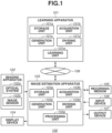
- Fig. 1 is a block diagram of the image processing system 100 according to the present embodiment.
- Fig. 2 illustrates an appearance of the image processing system 100.
- the image processing system 100 includes a learning apparatus 101, an imaging apparatus 102, an image estimation apparatus 103, a display device 104, a recording medium 105, an input device 106, an output device 107, and a network 108.
- the learning apparatus 101 includes a storage means (e.g., storage unit) 101a, an acquisition means (e.g., acquisition unit) 101b, a generation means (e.g., generation unit) 101c, a dividing means (dividing unit) 101d, and a learning means (e.g., learning unit) 101e.
- a storage means e.g., storage unit
- an acquisition means e.g., acquisition unit
- a generation means e.g., generation unit
- dividing means dividing unit
- learning means e.g., learning unit
- the imaging apparatus 102 includes an optical system 102a and an image sensor 102b.
- the optical system 102a collects light incident on the imaging apparatus 102 from a subject space.
- the image sensor 102b receives an optical image of a subject that has been formed via the optical system 102a to acquire a captured image 20.
- the image sensor 102b may be a charge coupled device (CCD) sensor or a complementary metal-oxide semiconductor (CMOS) sensor.
- CCD charge coupled device
- CMOS complementary metal-oxide semiconductor
- the imaging apparatus 102 transmits the obtained image to an acquisition unit 103b of the image estimation apparatus (e.g., image processing apparatus) 103, which will be described below.
- the imaging apparatus 102 can transmit an image capturing condition corresponding to the captured image 20, together with the captured image 20.
- the image capturing condition is a condition of image capturing that is to be used when the captured image 20 is acquired using the optical system 102a and the image sensor 102b.
- the image capturing condition includes a pixel pitch of the image sensor 102b, the type of an optical low-pass filter of the optical system 102a, and an ISO sensitivity.
- the image capturing condition can be a condition of development that is to be used when the captured image 20 is acquired from an undeveloped RAW image in the imaging apparatus 102.
- the image capturing condition includes noise removal strength, sharpness strength, and an image compression ratio.
- development is processing of converting a RAW image into an image file in a Joint Photographic Experts Group (JPEG) format or a Tag Image File Format (TIFF).
- JPEG Joint Photographic Experts Group
- TIFF Tag Image File Format
- Components that are not illustrated include a storage unit for storing images acquired in the imaging apparatus 102, a display unit for displaying the acquired images, a transmission unit for transmitting the acquired images to the outside, an output unit for causing the acquired images to be stored into an external storage medium, and a control unit for controlling each component of the imaging apparatus 102.
- the image estimation apparatus 103 includes a storage means (e.g., storage unit) 103a, the acquisition means (e.g., acquisition unit) 103b, a generation means (e.g., generation unit) 103c, a dividing means (e.g., dividing unit) 103d, and a processing means (e.g., estimation unit) 103e.
- the image estimation apparatus 103 generates an output image by performing image processing on the acquired captured image 20.
- the acquisition unit 103b acquires the captured image 20. As necessary, the acquisition unit 103b may acquire (e.g., receive) an image capturing condition corresponding to the captured image 20, together with the captured image 20.
- the generation unit 103c extracts a Y image (e.g., luminance image) and a plurality of chrominance images (e.g., first chrominance images) by performing YUV conversion on the acquired captured image 20.
- the luminance image is a grayscale image in which information regarding a luminance value is represented only by single-colour shading.
- the chrominance images are images respectively including information regarding U and information regarding V that are obtained after YUV conversion. The details of YUV conversion will be described below.
- the dividing unit 103d down-sizes the luminance image by transforming (e.g., dividing) the obtained luminance image.
- the processing unit 103e generates an estimated image (e.g., output image) by performing image processing of enlarging and enhancing resolution of the down-sized luminance image (e.g., input image).
- the processing unit 103e can perform image processing using an image capturing condition acquired by the acquisition unit 103b. For example, it is possible to perform image processing even on images where ground truth images corresponding to training images are acquired by arbitrary different imaging apparatuses, by using a pixel pitch of an image sensor, the type of an optical low-pass filter, and an image compression rate in addition to an input image at the time of learning of a machine learning model.
- the details of image processing that uses an image capturing condition will be described below.
- the captured image 20 can be an image captured by the imaging apparatus 102, or can be an image stored in the recording medium 105. Furthermore, an image originally represented in the grayscale, such as an infrared image or a distance image, can be used for the captured image 20.
- the image processing in the present embodiment uses a neural network.
- Information regarding a weight in the neural network is learned by the learning apparatus 101.
- the image estimation apparatus 103 reads out information regarding a weight from the storage unit 101a via the network 108, and stores the information into the storage unit 103a.
- Information regarding a weight that is to be stored can be a numerical value of the weight, or can be an encoded weight. The details of learning of weights and image processing that uses weights will be described below.
- the image estimation apparatus 103 has functions of performing development processing and other types of image processing as necessary.
- An output image is output to at least one of the display device 104, the recording medium 105, and the output device 107.
- the display device 104 is a liquid crystal display or a projector, for example. A user can check an image being processed, via the display device 104, and perform an image edit work via the input device 106.
- the recording medium 105 is a semiconductor memory, a hard disk, or a server on a network, for example.
- the input device 106 includes a keyboard and a mouse, for example.
- the output device 107 is a printer, for example.
- the image estimation apparatus 103 can display or output an image having been subjected to colouring processing. The colouring processing will be described below.
- a weight learning method (e.g., a method of manufacturing a learned model) to be executed by the learning apparatus 101 according to the present embodiment will be described with reference to Figs. 3 and 4 .
- Fig. 3 is a conceptual diagram illustrating learning (e.g., update) of a weight of a neural network.
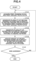
- Fig. 4 is a flowchart illustrating learning processing of a neural network.
- a convolutional neural network (CNN) 30 is used as a neural network.
- CNN convolutional neural network
- RNN recurrent neural network
- the learning (update) of a weight of the CNN 30 is performed using mini-batch learning.
- a weight is updated by obtaining errors between a plurality of ground truth images and corresponding estimated images.
- an L2 norm or an L1 norm can be used as an error function (e.g., loss function).
- an L2 norm or an L1 norm can be used as an error function (e.g., loss function).
- the embodiment is not limited to this, and online learning or batch learning can also be used.
- a convolution layer performs a calculation which involves convolving (e.g., applying) a filter to information input to the CNN 30, and calculates a sum of the input information and a bias. Furthermore, the convolution layer CN performs nonlinear conversion of the obtained calculation result based on an activating function. Each component of the filters and an initial value of the bias are arbitrarily set, and determined based on random numbers in the present embodiment.
- the activating function for example, a rectified linear unit (ReLU) or a sigmoid function can be used.
- Each convolution layer CN excluding a final layer outputs a feature map.
- the feature map has a four-dimensional array having dimensions in batch, longitudinal, traverse, and channel directions.
- a skip connection SC synthesizes feature maps output from noncontiguous layers.
- feature maps are synthesized using a method of obtaining a sum for each element.
- Feature maps can be synthesized by being concatenated (e.g., linked together) in the channel direction.
- a pixel shuffle is a method of enlarging a feature map.
- the feature map is turned into a high-resolution feature map.
- deconvolution or transposed convolution can be used in the enlargement of a feature map.
- a residual block RB is an element (block or module) consists of a plurality of convolution layers CN.
- learning can be performed using a network called a residual network, in which residual blocks are multilayered.
- the residual network is used, but not limited to this.
- a network can be multilayered using elements, such as inception modules or dense blocks.
- Processing load can be reduced by down-sizing a feature map in a layer close to an input layer, enlarging (up-sizing) a feature map in a layer close to an output layer, and reducing a size of a feature map in an intermediate layer, in the convolution layer CN as necessary.
- Pooling or stride can be used in the reduction of a feature map.
- Deconvolution or transposed convolution, pixel shuffle, or interpolation can be used in the enlargement of a feature map.
- FIG. 4 A flowchart illustrating learning processing of a neural network will now be described. Each step in Fig. 4 is mainly executed by the acquisition unit 101b, the generation unit 101c, the dividing unit 101d, and the learning unit 101e.
- step S101 acquires a first ground truth patch 10 (first ground truth image) and a corresponding first training patch 11 (first training image).
- the first ground truth patch 10 and the first training patch 11 are grayscale images at least including luminance information.
- the first ground truth patch 10 has a larger image size and a higher resolution as compared with those of the first training patch 11, and includes the same subject as that in the corresponding first training patch 11.
- a patch is an image which has a predetermined number of pixels.
- the first training patch 11 has 128 ⁇ 128 ⁇ 1 pixels
- the corresponding first ground truth patch 10 has 256 ⁇ 256 ⁇ 1 pixels.
- a magnification ratio of a patch is not limited to 200% in longitudinal and traverse directions, and can be any magnification ratio as long as the first training patch 11 and the corresponding first ground truth patch 10 can be acquired.
- the first training patch 11 and the corresponding first ground truth patch 10 are generated by numerical calculation.
- the present invention is not limited to this.
- the first training patch 11 and the corresponding first ground truth patch 10 can be acquired by capturing images of the same subject using optical systems with different focal lengths, and extracting corresponding portions in the obtained two images.
- the first training patch 11 can be generated by lowering the resolution of the first ground truth patch 10 by down-sampling.
- luminance patches (grayscale images) obtained by performing YUV conversion of colour patches can be used as the first ground truth patch 10 and the first training patch 11.
- a luminance patch and a plurality of chrominance patches can be generated.
- the luminance patch and the plurality of chrominance patches are generated from colour patches in accordance with the following formulas (1).
- the present embodiment is not limited to these, and other definitional formulas can be used.
- Formulas (1) are formulas to be used in conversion from a RGB colour space into a YUV colour space.
- the RGB colour space is represented using three colour channels corresponding to red, green, and blue.
- the YUV colour space is represented using a luminance channel (Y) and two chrominance channels (U and V).
- the acquisition unit 101b acquires the first ground truth patch 10 and the corresponding first training patch 11 that are represented in the grayscale, but the acquisition unit 101b can acquire a ground truth colour patch and a corresponding training colour patch each including a plurality of colour channels.
- the generation unit 101c generates the first ground truth patch 10 and the first training patch 11 from the ground truth colour patch and the training colour patch in accordance with formulas (1). Only either one of the first ground truth patch 10 and the first training patch 11 can be generated from a colour patch, and the other one can be acquired by the acquisition unit 101b as a luminance patch.
- step S102 division step
- the dividing unit 101d generates a plurality of second training patches 12 (second training images) by dividing the first training patch 11.
- the plurality of second training patches 12 is generated by reversible transformation in which information is not lost by division.
- the second training patches 12 are generated by arranging, in space directions (longitudinal and traverse directions), pixel values alternately extracted both in the longitudinal direction and the traverse direction of the first training patch 11.
- four second training patches 12 in a channel (depth) direction can be generated from one first training patch 11 in the channel direction.
- Each of the second training patches 12 has longitudinal and traverse sizes at least one of which is smaller, and has a lower resolution as compared with those of the corresponding first training patch 11.
- the sum of the numbers of pixels of the plurality of second training patches 12 is equal to the number of pixels of the first training patch 11.
- the first training patch 11 is equally divided into four second training patches 12 each of which has the same number of pixels.
- a patch generation method is not limited to this. It is sufficient that at least the first training patch 11 is reversibly transformed into a plurality of second training patches 12.
- a plurality of second training patches 12 can include different numbers of pixels. Not four but an arbitrary plural number of second training patches 12 can be generated.
- a frequency component obtained by performing multiresolution analysis by discrete wavelet transform can also be used.
- step S102 the dividing unit 101d generates a plurality of second ground truth patches 14 (second ground truth images) by dividing the first ground truth patch 10 similarly to the first training patch 11.
- the dividing unit 101d inputs an image capturing condition to the CNN 30 together with the plurality of second training patches 12, the dividing unit 101d can convert the first ground truth patch 10 into images (maps) including image capturing conditions of the respective pixels, based on an image capturing condition acquired by the acquisition unit 103b.
- step S103 the learning unit 101e generates a plurality of estimated patches 13 (estimated images) by performing image processing of the divided second training patches 12 using the CNN 30 (machine learning model).
- the plurality of estimated patches 13 are estimated images obtained by the CNN 30, and ideally correspond to the plurality of respective second ground truth patches 14.
- the learning unit 101e can input the image capturing conditions to the CNN 30.
- the learning unit 101e In a case where images including image capturing conditions of the respective pixels are input to the CNN 30 together with the second training patches 12, the learning unit 101e generates a plurality of estimated patches 13 by performing image processing that is based on the image capturing conditions, in addition to upscaling.
- step S104 the learning unit 101e updates a weight of the CNN 30 based on an error (e.g., loss) between the estimated patches 13 and the second ground truth patches 14.
- the weight includes a filter and a bias of each layer.
- a backpropagation method is used for the weight update.
- the method is not limited to this.
- step S105 the learning unit 101e determines whether the learning of the weight has been completed. The completion can be determined based on whether the number of times learning (weight update) is repeated has reached a predetermined iteration number, or whether a weight change amount in update is smaller than a predetermined value (threshold). In a case where it is determined that the learning has not been completed (NO in step S105), the processing returns to step S101, in which a new first training patch 11 and a corresponding first ground truth patch 10 are acquired. In contrast, in a case where it is determined that the learning has been completed (YES in step S105), the learning apparatus 101 ends learning, and stores information regarding the weight, into the storage unit 101a.
- Fig. 5 is a conceptual diagram illustrating output image generation of a neural network.
- Fig. 6 is a flowchart illustrating output image generation processing that uses a neural network. Each step in Fig. 6 is mainly executed by the acquisition unit 103b, the generation unit 103c, the dividing unit 103d, and the processing unit 103e of the image estimation apparatus (image processing apparatus) 103.
- step S201 acquires a captured image 20 (first colour image).
- the captured image 20 is an image including at least luminance information similarly to images in learning.
- the captured image 20 is a colour image transmitted from the imaging apparatus 102, however, the present invention is not limited to this.
- the captured image 20 can be an image stored in the storage unit 103a.
- the captured image 20 can be a grayscale image in which only luminance information is represented only by single-colour shading.
- An image capturing condition corresponding to the captured image 20 can be acquired together with the captured image 20, and used in the following process.
- step S202 the generation unit 103c extracts a Y image (luminance image) and a plurality of chrominance images (first chrominance images) by performing YUV conversion of the acquired captured image 20.
- the luminance image is a first grayscale image 21 in which only luminance information of the captured image 20 is represented only by single-colour shading.
- the plurality of chrominance images are a plurality of chrominance images 22 (first chrominance images) including information regarding a chrominance of the captured image 20.
- the Y image and the plurality of chrominance images can be generated from the captured image 20 in accordance with formulas (1).
- step S203 the dividing unit 103d generates a plurality of second grayscale images 23 by dividing the first grayscale image 21.
- the plurality of second grayscale images 23 is generated by reversible division in which information is not lost by division.
- each of the second grayscale images 23 has longitudinal and traverse sizes at least one of which is smaller, and has a lower resolution as compared with those of the first grayscale image 21.
- the sum of the numbers of pixels of the second grayscale images 23 is equal to the number of pixels of the first grayscale image 21. It is desirable that the plurality of second grayscale images 23 includes the same number of pixels (resolution). In a case where the plurality of second grayscale images 23 includes the same number of pixels (resolution), calculation amounts for the plurality of second grayscale images 23 become the same. It is therefore possible to streamline calculation in an estimation step to be described below. Because the division method of the first grayscale image 21 is similar to the transformation method of the first training patch 11 in step S102, the description will be omitted.
- step S204 the processing unit 103e generates a plurality of first estimated images 24 (third grayscale images) from the plurality of second grayscale images 23 by performing image processing using the CNN 30.
- Weight information used in the generation of the plurality of first estimated images 24 is weight information transmitted from the learning apparatus 101 and stored in the storage means 103a, and is weight information of a neural network similar to that in Fig. 3 .
- step S205 the processing unit 103e can further perform image processing on the plurality of first estimated images 24 as necessary.
- a second estimated image 25 (fourth grayscale image) can be generated by combining (synthesizing) the plurality of first estimated images 24.
- the second estimated image 25 is generated from the plurality of first estimated images 24 by performing a reverse operation of the method of transforming the first grayscale image 21 into the plurality of second grayscale images 23 in step S203. That is, in the present embodiment, the processing unit 103e can generate the second estimated image 25 by combining the plurality of first estimated images 24 in the space directions.
- the number of pixels of the second estimated image 25 is equal to the sum of the numbers of pixels of the plurality of first estimated images 24. Accordingly, in the case of upscaling a magnification ratio to the same magnification ratio, a calculation amount can be reduced as compared with a case where a colour image is used as an input image, by using the plurality of second grayscale images 23 obtained by down-sizing the first grayscale image 21, as input images to a machine learning model.
- the second estimated image 25 obtained by combining the plurality of first estimated images 24 is generated, and the image estimation apparatus 103 can also use the second estimated image 25 as an output image.
- step S206 the processing unit 103e can perform image processing of colouring the second estimated image 25.
- the processing unit 103e generates an estimated colour image 26 (second colour image) by performing colouring based on the second estimated image 25 and the plurality of chrominance images 22 generated in step S202.
- the estimated colour image 26 is an image obtained by upscaling the captured image 20.
- the colouring of a luminance image is performed in accordance with formulas (2).
- R Y + 1.13983
- V G Y ⁇ 0.39465 U ⁇ 0.58060
- V B Y + 2.03211 U
- Formulas (2) are formulas to be used in conversion from a YUV colour space into a RGB colour space.
- Formulas (2) represent a reverse operation of conversion from a RGB colour space into a YUV colour space that is performed in accordance with formulas (1).
- a reverse operation thereof needs to be used as a generation method of a colour image from a luminance image.
- the image estimation apparatus 103 can use the estimated colour image 26 as an output image.
- the processing unit 103e can use a plurality of interpolated chrominance images 27 (second chrominance images).
- the plurality of interpolated chrominance images 27 is generated by interpolating each of the chrominance images 22 (interpolation step).
- the method of generating the interpolated chrominance images 27 from the chrominance images 22 is not limited to this.
- the generation can be performed using a bilinear interpolation method and a bicubic interpolation method, or a method that uses a machine learning model.
- each of the plurality of interpolated chrominance images 27 has the same resolution (the number of pixels) as the second estimated image 25.
- the acquisition unit 103b acquires, in step S201, an image (e.g., infrared image or depth map) originally represented in the grayscale, it is sufficient to execute the processing in step S203 and subsequent steps without executing the processing in steps S201 and S202.
- the second estimated image 25 cannot be coloured.
- the present invention is not limited to this.
- the learning apparatus 101 and the image estimation apparatus 103 can be integrally formed. That is, learning processing and estimation processing can be performed in a single apparatus.
- an image processing system that obtains a high-resolution output image by using a grayscale image down-sized by reversible division in image processing that uses a machine learning model, as an input image.
- the image processing system 200 learns and executes image processing of upscaling an image using a machine learning model.
- the image processing system 200 differs from that in the first embodiment in that an imaging apparatus 202 acquires a captured image 20 and performs image processing.
- Fig. 7 is a block diagram of the image processing system 200 according to the present embodiment.
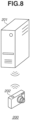
- Fig. 8 illustrates an appearance of the image processing system 200.
- the image processing system 200 includes a learning apparatus 201 and the imaging apparatus 202 that are connected via a network 203.
- the learning apparatus 201 and the imaging apparatus 202 need not be always connected via the network 203.
- the learning apparatus 201 includes a storage unit (storage means) 211, an acquisition unit (acquisition means) 212, a generation unit (generation means) 213, a dividing unit (dividing means) 214, and a learning unit (learning means) 215.
- a weight of a neural network is learned (updated) using these units to upscale the captured image 20.
- Information regarding a weight of a neural network is preliminarily learned by the learning apparatus 201 and stored in the storage unit 211. Because a learning (update) method of a weight of a neural network that is to be executed in the learning apparatus 201 is similar to that in the first embodiment, the description will be omitted.
- the imaging apparatus 202 includes an optical system 221, an image sensor 222, an image estimation unit 223, a storage unit 224, a recording medium 225a, a display unit 225b, an input unit 226, and a system controller 227.
- the imaging apparatus 202 generates an output image by capturing an image of a subject space and acquiring the captured image 20.
- the optical system 221 and the image sensor 222 in the imaging apparatus 202 are similar to those in the first embodiment, and thus the description will be omitted.
- the imaging apparatus 202 reads out information regarding a weight of a neural network from the storage unit 211 via the network 203, and stores the information into the storage unit 224.
- the image estimation unit 223 includes an acquisition unit 223a, a generation unit 223b, a dividing unit 223c, and a processing unit 223d.
- the acquisition unit 223a acquires, from the imaging apparatus 202, the captured image 20 and an image capturing condition corresponding to the captured image 20.
- the generation unit 223b and the dividing unit 223c are similar to the generation unit 103c and the dividing unit 103d, respectively, in the first embodiment.
- An output image is generated by performing image processing of the captured image 20 acquired by the acquisition unit 223a, based on weight information of a neural network stored in the storage unit 224.
- the processing unit 223d uses an image capturing condition corresponding to the captured image 20, in image processing.
- the output image is stored in the recording medium 225a.
- the stored output image is read out and displayed on the display unit 225b.
- the image estimation unit 223 can perform processing of generating an output image by reading out the captured image 20 and the image capturing condition that are stored in the recording medium 225a.
- the system controller 227 controls processing to be performed in the imaging apparatus 202.
- FIG. 9 is a flowchart illustrating output image generation processing that uses a neural network according to the present embodiment.
- Each step in the generation of a second estimated image 25 is mainly executed by the acquisition unit 223a (acquisition means), the generation unit (generation means) 223b, the dividing unit (dividing means) 223c, and the processing unit (estimation means) 223d of the image estimation unit 223.
- step S301 acquisition step
- the acquisition unit 223a acquires the captured image 20 and an image capturing condition corresponding to the captured image 20.
- the captured image 20 is a colour image, and is an image acquired by the imaging apparatus 202 and stored in the storage unit 224.
- Steps S302 (generation step) and S303 (division step) are similar to steps S202 and S203 in the first embodiment, and thus the description will be omitted.
- step S304 the processing unit 223d generates a plurality of first estimated images (third grayscale images) 24 from a plurality of second grayscale images 23 by performing image processing using a neural network.
- Weight information of a neural network used in the generation of the first estimated images 24 is weight information transmitted from the learning apparatus 201 and stored in the storage unit 224, and is weight information in a neural network similar to that in Fig. 3 .
- the processing unit 223d performs image processing using an ISO sensitivity as an image capturing condition in addition to the plurality of first estimated images 24.
- the ISO sensitivity is an image capturing condition indicating light sensitivity of a sensor. In a case where the ISO sensitivity is high, noise easily appears in an image. By using an ISO sensitivity as an image capturing condition, image processing can suppress excessive noise emphasis when a captured image 20 with high ISO sensitivity is upscaled.
- the image capturing condition is not limited to an ISO sensitivity.
- noise removal strength can also be used as an image capturing condition.
- image processing is performed in such a manner as to reduce high frequency components of an output image.
- sharpness strength can be used as an image capturing condition.
- image processing is performed in such a manner that high frequency components of an output image do not become excessive.
- an image compression rate can be used as an image capturing condition. In a case where an image compression rate of the captured image 20 is high (high frequency components of the captured image 20 are lost), image processing is performed in such a manner as to compensate for high frequency components of an output image.
- step S305 processing step
- the processing unit 223d generates an output image by combining and colouring the plurality of first estimated images 24. Because a combining method and a colouring method are similar to those in the first embodiment, the description will be omitted.
- the image processing system 300 causes a machine learning model to learn and execute image processing of upscaling an image.
- the image processing system 300 differs from that in the first embodiment in that the image processing system 300 includes a control apparatus 304 that acquires a captured image 20 from an imaging apparatus 302, and issues (transmits) a request for image processing on the captured image 20 to an image estimation apparatus (image processing apparatus) 303.
- a control apparatus 304 that acquires a captured image 20 from an imaging apparatus 302, and issues (transmits) a request for image processing on the captured image 20 to an image estimation apparatus (image processing apparatus) 303.
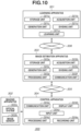
- Fig. 10 is a block diagram of the image processing system 300 according to the present embodiment.
- the image processing system 300 includes a learning apparatus 301, the imaging apparatus 302, the image estimation apparatus 303, and the control apparatus 304.
- the learning apparatus 301 and the image estimation apparatus 303 can be servers.
- the control apparatus 304 is a user terminal, such as a personal computer or a smartphone.
- the control apparatus 304 is connected to the image estimation apparatus 303 via a network 305.
- the image estimation apparatus 303 is connected to the learning apparatus 301 via a network 306. That is, the control apparatus 304 and the image estimation apparatus 303, and the image estimation apparatus 303 and the learning apparatus 301 are connected in such a manner that communication can be performed with each other.
- the learning apparatus 301 and the imaging apparatus 302 in the image processing system 300 have configurations similar to the learning apparatus 101 and the imaging apparatus 102, respectively, and thus the description will be omitted.
- the image estimation apparatus 303 includes a storage means 303a (e.g., storage unit), an acquisition means (e.g., acquisition unit) 303b, a generation means (e.g., generation unit) 303c, a dividing means (e.g., dividing unit) 303d, a processing means (e.g., estimation unit) 303e, and a communication means (e.g., receiving unit) 303f.
- a storage means 303a e.g., storage unit
- an acquisition means e.g., acquisition unit
- a generation means e.g., generation unit
- dividing means e.g., dividing unit
- processing means e.g., estimation unit
- a communication means e.g., receiving unit
- the storage unit 303a, the acquisition unit 303b, the generation unit 303c, the dividing unit 303d, and the processing unit 303e in the image estimation apparatus 303 are similar to the storage unit 103a, the acquisition unit 103b, the generation unit 103c, the dividing unit 103d, and the processing unit 103e, respectively.
- the control apparatus 304 includes a communication means (e.g., transmission unit) 304a, a display means (e.g., display unit) 304b, an input means (e.g., input unit) 304c, a processing means (e.g., processing unit) 304d, and a recording means 304e (e.g., a recording unit).
- the communication unit 304a can transmit a request for causing the image estimation apparatus 303 to execute processing on the captured image 20, to the image estimation apparatus 303.
- the communication unit 304a can also receive an output image processed by the image estimation apparatus 303.
- the communication unit 304a can communicate with the imaging apparatus 302.
- the display unit 304b displays various types of information.
- the various types of information to be displayed by the display unit 304b include, for example, the captured image 20 to be transmitted to the image estimation apparatus 303, or an output image received from the image estimation apparatus 303.
- the input unit 304c can input an instruction to start image processing, from the user.
- the processing unit 304d can perform image processing including colouring, on an output image received from the image estimation apparatus 303.
- the recording means 304e stores the captured image 20 acquired from the imaging apparatus 302, and an output image received from the image estimation apparatus 303.
- a method of transmitting the captured image 20 to be processed, to the image estimation apparatus 303 is not limited.
- the captured image 20 can be uploaded to the image estimation apparatus 303 simultaneously with the processing in step S401, or can be uploaded to the image estimation apparatus 303 before the processing in step S401.
- the captured image 20 can be an image stored in a server different from the image estimation apparatus 303.
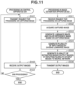
- FIG. 11 is a flowchart illustrating output image generation processing that uses a neural network according to the present embodiment.
- Image processing in the present embodiment is started in accordance with an image processing start instruction issued by the user via the control apparatus 304.
- step S401 (first transmission step), the communication unit 304a transmits a request for processing on the captured image 20 to the image estimation apparatus 303.
- the control apparatus 304 can transmit an ID for user authentication or an image capturing condition corresponding to the captured image 20, together with the request for processing on the captured image 20.
- step S402 the communication unit 304a receives an output image generated by the image estimation apparatus 303.
- step S501 the communication unit 303f receives the request for processing on the captured image 20 that has been transmitted from the communication unit 304a.
- the image estimation apparatus 303 executes the processing in step S502 and subsequent steps by receiving an instruction to execute processing on the captured image 20.
- step S502 the acquisition unit 303b acquires the captured image 20.
- the captured image 20 is an image transmitted from the control apparatus 304.
- the acquisition unit 303b can acquire an image capturing condition corresponding to the captured image 20, together with the captured image 20.
- the processing in step S501 and the processing in step S502 can be simultaneously executed. Because the processing in steps S503 to S505 is similar to the processing in steps S202 to S204, the description will be omitted.
- step S506 the image estimation apparatus 303 transmits an output image to the control apparatus 304.
- An output image to be transmitted by the image estimation apparatus 303 includes any of a plurality of first estimated images 24, a second estimated image 25 generated from the plurality of first estimated images 24, and an estimated colour image 26.
- the control apparatus 304 merely issues a request for processing on a specific image. Actual image processing is performed by the image estimation apparatus 303.
- processing load on the user terminal can be reduced. It accordingly becomes possible for a user to obtain an output image with low processing load.
- the present embodiment can also be implemented by processing of supplying a program for implementing one or more functions of the above-described embodiments, to a system or an apparatus via a network or a storage medium, and one or more processors in a computer of the system or the apparatus reading out and executing the program.
- the present embodiment can also be implemented by a circuit for implementing one or more functions (for example, an application specific integrated circuit (ASIC)).
- ASIC application specific integrated circuit
- an image processing method an image processing apparatus, a program, and a storage medium that can obtain a high-resolution output image in image processing that uses a machine learning model, as an input image.
- the image processing apparatus is only required to be an apparatus having an image processing function according to the present embodiment, and can be implemented in the form of an imaging apparatus or a personal computer.
- Embodiment(s) of the present invention can also be realized by a computer of a system or apparatus that reads out and executes computer executable instructions (e.g., one or more programs) recorded on a storage medium (which may also be referred to more fully as a 'non-transitory computer-readable storage medium') to perform the functions of one or more of the above-described embodiment(s) and/or that includes one or more circuits (e.g., application specific integrated circuit (ASIC)) for performing the functions of one or more of the above-described embodiment(s), and by a method performed by the computer of the system or apparatus by, for example, reading out and executing the computer executable instructions from the storage medium to perform the functions of one or more of the above-described embodiment(s) and/or controlling the one or more circuits to perform the functions of one or more of the above-described embodiment(s).
- computer executable instructions e.g., one or more programs
- a storage medium which may also be referred to more fully as
- the computer may comprise one or more processors (e.g., central processing unit (CPU), micro processing unit (MPU)) and may include a network of separate computers or separate processors to read out and execute the computer executable instructions.
- the computer executable instructions may be provided to the computer, for example, from a network or the storage medium.
- the storage medium may include, for example, one or more of a hard disk, a random-access memory (RAM), a read only memory (ROM), a storage of distributed computing systems, an optical disk (such as a compact disc (CD), digital versatile disc (DVD), or Blu-ray Disc (BD) TM ), a flash memory device, a memory card, and the like.
Landscapes
- Engineering & Computer Science (AREA)
- Theoretical Computer Science (AREA)
- Physics & Mathematics (AREA)
- General Physics & Mathematics (AREA)
- Computer Vision & Pattern Recognition (AREA)
- Evolutionary Computation (AREA)
- Artificial Intelligence (AREA)
- Software Systems (AREA)
- Health & Medical Sciences (AREA)
- Computing Systems (AREA)
- General Health & Medical Sciences (AREA)
- Multimedia (AREA)
- Biomedical Technology (AREA)
- Life Sciences & Earth Sciences (AREA)
- Biophysics (AREA)
- Computational Linguistics (AREA)
- Data Mining & Analysis (AREA)
- Molecular Biology (AREA)
- General Engineering & Computer Science (AREA)
- Mathematical Physics (AREA)
- Signal Processing (AREA)
- Medical Informatics (AREA)
- Databases & Information Systems (AREA)
- Image Processing (AREA)
- Image Analysis (AREA)
Abstract
Description
- The present invention relates to image processing method that uses a machine learning model.
-
Japanese Patent Application Laid-Open No. 2019-175107 Japanese Patent Application Laid-Open No. 2019-175107 - In the image processing method discussed in
Japanese Patent Application Laid-Open No. 2019-175107 - In
Japanese Patent Application Laid-Open No. 2019-175107 Japanese Patent Application Laid-Open No. 2019-175107 - In view of the foregoing, the present invention is directed to obtaining a high-resolution output image with image processing that uses a machine learning model.
- According to a first aspect of the present invention, there is provided an image processing method as specified in claims 1 to 11. According to a second aspect of the present invention, there is provided a program as specified in
claim 12. According to a third aspect of the present invention, there is provided a storage medium as specified inclaim 13. According to a fourth aspect of the present invention, there is provided an image processing apparatus as specified inclaim 14. According to a fifth aspect of the present invention, there is provided a learning apparatus as specified in claim 15. According to a sixth aspect of the present invention, there is provided a manufacturing method of a learned model as specified in claim 16. According to a seventh aspect of the present invention, there is provided a program as specified in claim 17. According to an eighth aspect of the present invention, there is provided an image processing system as specified in claim 18. According to a ninth aspect of the present invention, there is provided an image processing system as specified in claim 19. - Further features of the present invention will become apparent from the following description of embodiments with reference to the attached drawings.
-
-
Fig. 1 is a block diagram of an image processing system according to a first embodiment. -
Fig. 2 is an appearance of the image processing system according to the first embodiment. -
Fig. 3 is a conceptual diagram illustrating a learning method of a weight of a neural network according to the first embodiment. -
Fig. 4 is a flowchart illustrating learning processing of a weight of a neural network according to the first embodiment. -
Fig. 5 is a conceptual diagram illustrating an output image generation method that uses a neural network according to the first embodiment. -
Fig. 6 is a flowchart illustrating output image generation processing that uses a neural network according to the first embodiment. -
Fig. 7 is a block diagram of an image processing system according to a second embodiment. -
Fig. 8 is an appearance of the image processing system according to the second embodiment. -
Fig. 9 is a flowchart illustrating output image generation processing that uses a neural network according to the second embodiment. -
Fig. 10 is a block diagram of an image processing system according to a third embodiment. -
Fig. 11 is a flowchart illustrating output image generation processing that uses a neural network according to the third embodiment. - Some embodiments of the present invention will be described in detail below with reference to the accompanying drawings. In the following drawings, the same members are assigned the same reference numerals, and the redundant description will be omitted.
- Before specifically describing the embodiments, the summary of the present embodiment will be described. In the present embodiment, a machine learning model is used to upscale a luminance image (grayscale image). In the present embodiment, image processing of performing enlargement and resolution enhancement of an image will be referred to as upscaling. The machine learning model in the present embodiment is generated by performing learning (or training) a neural network. The neural network comprises a filter that performs a convolution on an image (e.g., a convolution filter), a bias to be added to the image, and an activating function for performing nonlinear conversion. The filter and the bias, in combination, define weights of the neural network. The filter and the bias are learned (or updated) by using a training image and a corresponding ground truth image. In the present embodiment, the learning of a machine learning model is performed by using images represented in the grayscale, as training images and ground truth images.
- An image processing method in the present embodiment includes a step of generating, by dividing a first grayscale image, a plurality of second grayscale images. Each of the plurality of second grayscale images has less number of (i.e., fewer) pixels than that of the first grayscale image. The image processing method further includes an estimation (or inference) step for generating a plurality of upscaled third grayscale images by inputting the plurality of second grayscale images to a machine learning model.
- In the present embodiment, an input image to a machine learning model is a grayscale image down-sized from an original grayscale image by reversibly dividing the original grayscale image. When an input image is generated from a grayscale image, an original grayscale image can be reversibly down-sized by dividing the original grayscale image into a plurality of grayscale images. It is accordingly possible to reduce loss of information that is caused by down-sizing. A highly-accurate estimated image (e.g., output image) can therefore be obtained. Because an input image is an image obtained by down-sizing a grayscale image with less information (i.e., fewer channels) than that of a colour image, it is possible to reduce the processing load (e.g., number of calculations) associated with the image processing. Consequently, the reduction in the complexity of the imaging processing can speed up the image processing, which also serves as one of features of the present embodiment.
- The above-described image processing method is one example, and the present invention is not limited to this. The details of other image processing methods will be described in the following embodiments.
- An
image processing system 100 according to a first embodiment of the present invention will be described. In the present embodiment, theimage processing system 100 learns and executes image processing of upscaling an image using a machine learning model. -
Fig. 1 is a block diagram of theimage processing system 100 according to the present embodiment.Fig. 2 illustrates an appearance of theimage processing system 100. Theimage processing system 100 includes alearning apparatus 101, animaging apparatus 102, animage estimation apparatus 103, adisplay device 104, arecording medium 105, aninput device 106, anoutput device 107, and anetwork 108. - The
learning apparatus 101 includes a storage means (e.g., storage unit) 101a, an acquisition means (e.g., acquisition unit) 101b, a generation means (e.g., generation unit) 101c, a dividing means (dividing unit) 101d, and a learning means (e.g., learning unit) 101e. - The
imaging apparatus 102 includes anoptical system 102a and animage sensor 102b. Theoptical system 102a collects light incident on theimaging apparatus 102 from a subject space. Theimage sensor 102b receives an optical image of a subject that has been formed via theoptical system 102a to acquire a capturedimage 20. Theimage sensor 102b may be a charge coupled device (CCD) sensor or a complementary metal-oxide semiconductor (CMOS) sensor. - The
imaging apparatus 102 transmits the obtained image to anacquisition unit 103b of the image estimation apparatus (e.g., image processing apparatus) 103, which will be described below. As necessary, theimaging apparatus 102 can transmit an image capturing condition corresponding to the capturedimage 20, together with the capturedimage 20. The image capturing condition is a condition of image capturing that is to be used when the capturedimage 20 is acquired using theoptical system 102a and theimage sensor 102b. For example, the image capturing condition includes a pixel pitch of theimage sensor 102b, the type of an optical low-pass filter of theoptical system 102a, and an ISO sensitivity. Alternatively, the image capturing condition can be a condition of development that is to be used when the capturedimage 20 is acquired from an undeveloped RAW image in theimaging apparatus 102. For example, the image capturing condition includes noise removal strength, sharpness strength, and an image compression ratio. In the present embodiment, development is processing of converting a RAW image into an image file in a Joint Photographic Experts Group (JPEG) format or a Tag Image File Format (TIFF). - Components that are not illustrated include a storage unit for storing images acquired in the
imaging apparatus 102, a display unit for displaying the acquired images, a transmission unit for transmitting the acquired images to the outside, an output unit for causing the acquired images to be stored into an external storage medium, and a control unit for controlling each component of theimaging apparatus 102. - The
image estimation apparatus 103 includes a storage means (e.g., storage unit) 103a, the acquisition means (e.g., acquisition unit) 103b, a generation means (e.g., generation unit) 103c, a dividing means (e.g., dividing unit) 103d, and a processing means (e.g., estimation unit) 103e. Theimage estimation apparatus 103 generates an output image by performing image processing on the acquired capturedimage 20. - The
acquisition unit 103b acquires the capturedimage 20. As necessary, theacquisition unit 103b may acquire (e.g., receive) an image capturing condition corresponding to the capturedimage 20, together with the capturedimage 20. - The
generation unit 103c extracts a Y image (e.g., luminance image) and a plurality of chrominance images (e.g., first chrominance images) by performing YUV conversion on the acquired capturedimage 20. The luminance image is a grayscale image in which information regarding a luminance value is represented only by single-colour shading. The chrominance images are images respectively including information regarding U and information regarding V that are obtained after YUV conversion. The details of YUV conversion will be described below. - The
dividing unit 103d down-sizes the luminance image by transforming (e.g., dividing) the obtained luminance image. - The
processing unit 103e generates an estimated image (e.g., output image) by performing image processing of enlarging and enhancing resolution of the down-sized luminance image (e.g., input image). Theprocessing unit 103e can perform image processing using an image capturing condition acquired by theacquisition unit 103b. For example, it is possible to perform image processing even on images where ground truth images corresponding to training images are acquired by arbitrary different imaging apparatuses, by using a pixel pitch of an image sensor, the type of an optical low-pass filter, and an image compression rate in addition to an input image at the time of learning of a machine learning model. The details of image processing that uses an image capturing condition will be described below. The capturedimage 20 can be an image captured by theimaging apparatus 102, or can be an image stored in therecording medium 105. Furthermore, an image originally represented in the grayscale, such as an infrared image or a distance image, can be used for the capturedimage 20. - The image processing in the present embodiment uses a neural network. Information regarding a weight in the neural network is learned by the
learning apparatus 101. Theimage estimation apparatus 103 reads out information regarding a weight from thestorage unit 101a via thenetwork 108, and stores the information into thestorage unit 103a. Information regarding a weight that is to be stored can be a numerical value of the weight, or can be an encoded weight. The details of learning of weights and image processing that uses weights will be described below. Theimage estimation apparatus 103 has functions of performing development processing and other types of image processing as necessary. - An output image is output to at least one of the
display device 104, therecording medium 105, and theoutput device 107. Thedisplay device 104 is a liquid crystal display or a projector, for example. A user can check an image being processed, via thedisplay device 104, and perform an image edit work via theinput device 106. Therecording medium 105 is a semiconductor memory, a hard disk, or a server on a network, for example. Theinput device 106 includes a keyboard and a mouse, for example. Theoutput device 107 is a printer, for example. Theimage estimation apparatus 103 can display or output an image having been subjected to colouring processing. The colouring processing will be described below. - A weight learning method (e.g., a method of manufacturing a learned model) to be executed by the
learning apparatus 101 according to the present embodiment will be described with reference toFigs. 3 and4 .Fig. 3 is a conceptual diagram illustrating learning (e.g., update) of a weight of a neural network.Fig. 4 is a flowchart illustrating learning processing of a neural network. In the present embodiment, a convolutional neural network (CNN) 30 is used as a neural network. The present embodiment is not limited to this. For example, a recurrent neural network (RNN) can be used. - In the present embodiment, the learning (update) of a weight of the
CNN 30 is performed using mini-batch learning. In the mini-batch learning, a weight is updated by obtaining errors between a plurality of ground truth images and corresponding estimated images. For example, an L2 norm or an L1 norm can be used as an error function (e.g., loss function). Nevertheless, the embodiment is not limited to this, and online learning or batch learning can also be used. - A convolution layer (CN) performs a calculation which involves convolving (e.g., applying) a filter to information input to the
CNN 30, and calculates a sum of the input information and a bias. Furthermore, the convolution layer CN performs nonlinear conversion of the obtained calculation result based on an activating function. Each component of the filters and an initial value of the bias are arbitrarily set, and determined based on random numbers in the present embodiment. As the activating function, for example, a rectified linear unit (ReLU) or a sigmoid function can be used. Each convolution layer CN excluding a final layer outputs a feature map. In the present embodiment, the feature map has a four-dimensional array having dimensions in batch, longitudinal, traverse, and channel directions. - A skip connection SC synthesizes feature maps output from noncontiguous layers. In the present embodiment, feature maps are synthesized using a method of obtaining a sum for each element. Feature maps can be synthesized by being concatenated (e.g., linked together) in the channel direction.
- A pixel shuffle (PS) is a method of enlarging a feature map. In the present embodiment, by enlarging a low-resolution feature map in a layer close to an output layer, the feature map is turned into a high-resolution feature map. For example, deconvolution or transposed convolution can be used in the enlargement of a feature map.
- A residual block RB is an element (block or module) consists of a plurality of convolution layers CN. To perform more accurate learning, learning can be performed using a network called a residual network, in which residual blocks are multilayered. In the present embodiment, the residual network is used, but not limited to this. For example, a network can be multilayered using elements, such as inception modules or dense blocks.
- Processing load can be reduced by down-sizing a feature map in a layer close to an input layer, enlarging (up-sizing) a feature map in a layer close to an output layer, and reducing a size of a feature map in an intermediate layer, in the convolution layer CN as necessary. Pooling or stride can be used in the reduction of a feature map. Deconvolution or transposed convolution, pixel shuffle, or interpolation can be used in the enlargement of a feature map.
- A flowchart illustrating learning processing of a neural network will now be described. Each step in
Fig. 4 is mainly executed by theacquisition unit 101b, thegeneration unit 101c, thedividing unit 101d, and thelearning unit 101e. - In step S101 (acquisition step), the
acquisition unit 101b acquires a first ground truth patch 10 (first ground truth image) and a corresponding first training patch 11 (first training image). The firstground truth patch 10 and thefirst training patch 11 are grayscale images at least including luminance information. In the present embodiment, the firstground truth patch 10 has a larger image size and a higher resolution as compared with those of thefirst training patch 11, and includes the same subject as that in the correspondingfirst training patch 11. A patch is an image which has a predetermined number of pixels. For example, thefirst training patch 11 has 128 × 128 × 1 pixels, and the corresponding firstground truth patch 10 has 256 × 256 × 1 pixels. A magnification ratio of a patch is not limited to 200% in longitudinal and traverse directions, and can be any magnification ratio as long as thefirst training patch 11 and the corresponding firstground truth patch 10 can be acquired. In the present embodiment, thefirst training patch 11 and the corresponding firstground truth patch 10 are generated by numerical calculation. However, the present invention is not limited to this. For example, thefirst training patch 11 and the corresponding firstground truth patch 10 can be acquired by capturing images of the same subject using optical systems with different focal lengths, and extracting corresponding portions in the obtained two images. Alternatively, thefirst training patch 11 can be generated by lowering the resolution of the firstground truth patch 10 by down-sampling. Furthermore, luminance patches (grayscale images) obtained by performing YUV conversion of colour patches can be used as the firstground truth patch 10 and thefirst training patch 11. By performing YUV conversion of colour patches, a luminance patch and a plurality of chrominance patches can be generated. The luminance patch and the plurality of chrominance patches are generated from colour patches in accordance with the following formulas (1). Nevertheless, the present embodiment is not limited to these, and other definitional formulas can be used.
- Formulas (1) are formulas to be used in conversion from a RGB colour space into a YUV colour space. The RGB colour space is represented using three colour channels corresponding to red, green, and blue. On the other hand, the YUV colour space is represented using a luminance channel (Y) and two chrominance channels (U and V).
- In the present embodiment, the
acquisition unit 101b acquires the firstground truth patch 10 and the correspondingfirst training patch 11 that are represented in the grayscale, but theacquisition unit 101b can acquire a ground truth colour patch and a corresponding training colour patch each including a plurality of colour channels. In this case, thegeneration unit 101c generates the firstground truth patch 10 and thefirst training patch 11 from the ground truth colour patch and the training colour patch in accordance with formulas (1). Only either one of the firstground truth patch 10 and thefirst training patch 11 can be generated from a colour patch, and the other one can be acquired by theacquisition unit 101b as a luminance patch. - In step S102 (division step), the
dividing unit 101d generates a plurality of second training patches 12 (second training images) by dividing thefirst training patch 11. - The plurality of
second training patches 12 is generated by reversible transformation in which information is not lost by division. In the present embodiment, thesecond training patches 12 are generated by arranging, in space directions (longitudinal and traverse directions), pixel values alternately extracted both in the longitudinal direction and the traverse direction of thefirst training patch 11. At this time, foursecond training patches 12 in a channel (depth) direction can be generated from onefirst training patch 11 in the channel direction. Each of thesecond training patches 12 has longitudinal and traverse sizes at least one of which is smaller, and has a lower resolution as compared with those of the correspondingfirst training patch 11. Furthermore, because thesecond training patches 12 are reversibly transformed, the sum of the numbers of pixels of the plurality ofsecond training patches 12 is equal to the number of pixels of thefirst training patch 11. - In the present embodiment, the
first training patch 11 is equally divided into foursecond training patches 12 each of which has the same number of pixels. However, a patch generation method is not limited to this. It is sufficient that at least thefirst training patch 11 is reversibly transformed into a plurality ofsecond training patches 12. For example, a plurality ofsecond training patches 12 can include different numbers of pixels. Not four but an arbitrary plural number ofsecond training patches 12 can be generated. Furthermore, a frequency component obtained by performing multiresolution analysis by discrete wavelet transform can also be used. - By reversibly transforming the
first training patch 11 represented in the grayscale, and using a plurality ofsecond training patches 12 down-sized in the space directions, as input images to theCNN 30 in this manner, it is possible to reduce a calculation amount in theCNN 30. Furthermore, because information is not lost in a plurality ofsecond training patches 12 by the division of thefirst training patch 11, it is possible to perform image processing highly accurately. - In step S102, the
dividing unit 101d generates a plurality of second ground truth patches 14 (second ground truth images) by dividing the firstground truth patch 10 similarly to thefirst training patch 11. In the case of thedividing unit 101d inputs an image capturing condition to theCNN 30 together with the plurality ofsecond training patches 12, thedividing unit 101d can convert the firstground truth patch 10 into images (maps) including image capturing conditions of the respective pixels, based on an image capturing condition acquired by theacquisition unit 103b. - Subsequently, in step S103 (estimation step), the
learning unit 101e generates a plurality of estimated patches 13 (estimated images) by performing image processing of the dividedsecond training patches 12 using the CNN 30 (machine learning model). The plurality of estimatedpatches 13 are estimated images obtained by theCNN 30, and ideally correspond to the plurality of respective secondground truth patches 14. By concatenating (e.g., linking together) images including image capturing conditions of the respective pixels, in the channel direction of the plurality ofsecond training patches 12, thelearning unit 101e can input the image capturing conditions to theCNN 30. In a case where images including image capturing conditions of the respective pixels are input to theCNN 30 together with thesecond training patches 12, thelearning unit 101e generates a plurality of estimatedpatches 13 by performing image processing that is based on the image capturing conditions, in addition to upscaling. - Subsequently, in step S104 (update step), the
learning unit 101e updates a weight of theCNN 30 based on an error (e.g., loss) between the estimatedpatches 13 and the secondground truth patches 14. The weight includes a filter and a bias of each layer. In the present embodiment, a backpropagation method is used for the weight update. However, the method is not limited to this. - In step S105, the
learning unit 101e determines whether the learning of the weight has been completed. The completion can be determined based on whether the number of times learning (weight update) is repeated has reached a predetermined iteration number, or whether a weight change amount in update is smaller than a predetermined value (threshold). In a case where it is determined that the learning has not been completed (NO in step S105), the processing returns to step S101, in which a newfirst training patch 11 and a corresponding firstground truth patch 10 are acquired. In contrast, in a case where it is determined that the learning has been completed (YES in step S105), thelearning apparatus 101 ends learning, and stores information regarding the weight, into thestorage unit 101a. - Output image generation processing according to the present embodiment will now be described with reference to
Figs. 5 and6 . -
Fig. 5 is a conceptual diagram illustrating output image generation of a neural network.Fig. 6 is a flowchart illustrating output image generation processing that uses a neural network. Each step inFig. 6 is mainly executed by theacquisition unit 103b, thegeneration unit 103c, thedividing unit 103d, and theprocessing unit 103e of the image estimation apparatus (image processing apparatus) 103. - In step S201 (acquisition step), the
acquisition unit 103b acquires a captured image 20 (first colour image). The capturedimage 20 is an image including at least luminance information similarly to images in learning. In the present embodiment, the capturedimage 20 is a colour image transmitted from theimaging apparatus 102, however, the present invention is not limited to this. For example, the capturedimage 20 can be an image stored in thestorage unit 103a. Furthermore, the capturedimage 20 can be a grayscale image in which only luminance information is represented only by single-colour shading. An image capturing condition corresponding to the capturedimage 20 can be acquired together with the capturedimage 20, and used in the following process. - In step S202 (generation step), the
generation unit 103c extracts a Y image (luminance image) and a plurality of chrominance images (first chrominance images) by performing YUV conversion of the acquired capturedimage 20. The luminance image is a firstgrayscale image 21 in which only luminance information of the capturedimage 20 is represented only by single-colour shading. The plurality of chrominance images are a plurality of chrominance images 22 (first chrominance images) including information regarding a chrominance of the capturedimage 20. The Y image and the plurality of chrominance images can be generated from the capturedimage 20 in accordance with formulas (1). - In step S203 (division step), the
dividing unit 103d generates a plurality of secondgrayscale images 23 by dividing the firstgrayscale image 21. - At this time, the plurality of second
grayscale images 23 is generated by reversible division in which information is not lost by division. Thus, each of the secondgrayscale images 23 has longitudinal and traverse sizes at least one of which is smaller, and has a lower resolution as compared with those of the firstgrayscale image 21. Furthermore, because the secondgrayscale images 23 are reversibly transformed, the sum of the numbers of pixels of the secondgrayscale images 23 is equal to the number of pixels of the firstgrayscale image 21. It is desirable that the plurality of secondgrayscale images 23 includes the same number of pixels (resolution). In a case where the plurality of secondgrayscale images 23 includes the same number of pixels (resolution), calculation amounts for the plurality of secondgrayscale images 23 become the same. It is therefore possible to streamline calculation in an estimation step to be described below. Because the division method of the firstgrayscale image 21 is similar to the transformation method of thefirst training patch 11 in step S102, the description will be omitted. - In step S204 (estimation step), the
processing unit 103e generates a plurality of first estimated images 24 (third grayscale images) from the plurality of secondgrayscale images 23 by performing image processing using theCNN 30. Weight information used in the generation of the plurality of first estimatedimages 24 is weight information transmitted from thelearning apparatus 101 and stored in the storage means 103a, and is weight information of a neural network similar to that inFig. 3 . - In step S205 (combining step), the
processing unit 103e can further perform image processing on the plurality of first estimatedimages 24 as necessary. For example, a second estimated image 25 (fourth grayscale image) can be generated by combining (synthesizing) the plurality of first estimatedimages 24. At this time, the second estimatedimage 25 is generated from the plurality of first estimatedimages 24 by performing a reverse operation of the method of transforming the firstgrayscale image 21 into the plurality of secondgrayscale images 23 in step S203. That is, in the present embodiment, theprocessing unit 103e can generate the second estimatedimage 25 by combining the plurality of first estimatedimages 24 in the space directions. At this time, the number of pixels of the second estimatedimage 25 is equal to the sum of the numbers of pixels of the plurality of first estimatedimages 24. Accordingly, in the case of upscaling a magnification ratio to the same magnification ratio, a calculation amount can be reduced as compared with a case where a colour image is used as an input image, by using the plurality of secondgrayscale images 23 obtained by down-sizing the firstgrayscale image 21, as input images to a machine learning model. The second estimatedimage 25 obtained by combining the plurality of first estimatedimages 24 is generated, and theimage estimation apparatus 103 can also use the second estimatedimage 25 as an output image. - Furthermore, in step S206 (colouring step), the
processing unit 103e can perform image processing of colouring the second estimatedimage 25. At this time, theprocessing unit 103e generates an estimated colour image 26 (second colour image) by performing colouring based on the second estimatedimage 25 and the plurality ofchrominance images 22 generated in step S202. The estimatedcolour image 26 is an image obtained by upscaling the capturedimage 20. In the present embodiment, the colouring of a luminance image is performed in accordance with formulas (2).
- Formulas (2) are formulas to be used in conversion from a YUV colour space into a RGB colour space. Formulas (2) represent a reverse operation of conversion from a RGB colour space into a YUV colour space that is performed in accordance with formulas (1). In a case where other definitional formulas are used as a generation method of a luminance image from a colour image, a reverse operation thereof needs to be used as a generation method of a colour image from a luminance image. In a case where the estimated
colour image 26 obtained by colouring the second estimatedimage 25 is generated, theimage estimation apparatus 103 can use the estimatedcolour image 26 as an output image. - Furthermore, to generate the estimated
colour image 26, theprocessing unit 103e can use a plurality of interpolated chrominance images 27 (second chrominance images). To achieve higher resolution, the plurality of interpolatedchrominance images 27 is generated by interpolating each of the chrominance images 22 (interpolation step). The method of generating the interpolatedchrominance images 27 from thechrominance images 22 is not limited to this. For example, the generation can be performed using a bilinear interpolation method and a bicubic interpolation method, or a method that uses a machine learning model. At this time, it is desirable that each of the plurality of interpolatedchrominance images 27 has the same resolution (the number of pixels) as the second estimatedimage 25. By colouring the second estimatedimage 25 using the plurality of interpolatedchrominance images 27 having the same resolution as the second estimatedimage 25, it is possible to reduce noise attributed to colouring, and obtain a more accurate estimatedcolour image 26. - In the present embodiment, the description has been given of the method of acquiring the captured
image 20 in step S201, generating the firstgrayscale image 21 from the capturedimage 20 in step S202, and generating an output image in step S203 and subsequent steps. Nevertheless, in a case where theacquisition unit 103b acquires, in step S201, an image (e.g., infrared image or depth map) originally represented in the grayscale, it is sufficient to execute the processing in step S203 and subsequent steps without executing the processing in steps S201 and S202. In this case, because information regarding a chrominance of the capturedimage 20 is not obtained, the second estimatedimage 25 cannot be coloured. - In the present embodiment, the description has been given of an example case where the
learning apparatus 101 and theimage estimation apparatus 103 are separate apparatuses. However, the present invention is not limited to this. Thelearning apparatus 101 and theimage estimation apparatus 103 can be integrally formed. That is, learning processing and estimation processing can be performed in a single apparatus. - According to the present embodiment with the above-described configuration, it is possible to provide an image processing system that obtains a high-resolution output image by using a grayscale image down-sized by reversible division in image processing that uses a machine learning model, as an input image.
- An
image processing system 200 according to a second embodiment of the present invention will now be described. Theimage processing system 200 according to the present embodiment learns and executes image processing of upscaling an image using a machine learning model. - The
image processing system 200 according to the present embodiment differs from that in the first embodiment in that animaging apparatus 202 acquires a capturedimage 20 and performs image processing. -
Fig. 7 is a block diagram of theimage processing system 200 according to the present embodiment.Fig. 8 illustrates an appearance of theimage processing system 200. Theimage processing system 200 includes alearning apparatus 201 and theimaging apparatus 202 that are connected via anetwork 203. Thelearning apparatus 201 and theimaging apparatus 202 need not be always connected via thenetwork 203. - The
learning apparatus 201 includes a storage unit (storage means) 211, an acquisition unit (acquisition means) 212, a generation unit (generation means) 213, a dividing unit (dividing means) 214, and a learning unit (learning means) 215. A weight of a neural network is learned (updated) using these units to upscale the capturedimage 20. Information regarding a weight of a neural network is preliminarily learned by thelearning apparatus 201 and stored in thestorage unit 211. Because a learning (update) method of a weight of a neural network that is to be executed in thelearning apparatus 201 is similar to that in the first embodiment, the description will be omitted. - The
imaging apparatus 202 includes anoptical system 221, animage sensor 222, animage estimation unit 223, astorage unit 224, arecording medium 225a, adisplay unit 225b, aninput unit 226, and asystem controller 227. Theimaging apparatus 202 generates an output image by capturing an image of a subject space and acquiring the capturedimage 20. Theoptical system 221 and theimage sensor 222 in theimaging apparatus 202 are similar to those in the first embodiment, and thus the description will be omitted. Theimaging apparatus 202 reads out information regarding a weight of a neural network from thestorage unit 211 via thenetwork 203, and stores the information into thestorage unit 224. - The
image estimation unit 223 includes anacquisition unit 223a, ageneration unit 223b, adividing unit 223c, and aprocessing unit 223d. Theacquisition unit 223a acquires, from theimaging apparatus 202, the capturedimage 20 and an image capturing condition corresponding to the capturedimage 20. Thegeneration unit 223b and thedividing unit 223c are similar to thegeneration unit 103c and thedividing unit 103d, respectively, in the first embodiment. An output image is generated by performing image processing of the capturedimage 20 acquired by theacquisition unit 223a, based on weight information of a neural network stored in thestorage unit 224. In the present embodiment, theprocessing unit 223d uses an image capturing condition corresponding to the capturedimage 20, in image processing. - The output image is stored in the
recording medium 225a. In a case where an estimated image display instruction is issued from the user via theinput unit 226, the stored output image is read out and displayed on thedisplay unit 225b. Theimage estimation unit 223 can perform processing of generating an output image by reading out the capturedimage 20 and the image capturing condition that are stored in therecording medium 225a. Thesystem controller 227 controls processing to be performed in theimaging apparatus 202. - Output image generation according to the present embodiment will now be described.
Fig. 9 is a flowchart illustrating output image generation processing that uses a neural network according to the present embodiment. Each step in the generation of a second estimatedimage 25 is mainly executed by theacquisition unit 223a (acquisition means), the generation unit (generation means) 223b, the dividing unit (dividing means) 223c, and the processing unit (estimation means) 223d of theimage estimation unit 223. - In step S301 (acquisition step), the
acquisition unit 223a acquires the capturedimage 20 and an image capturing condition corresponding to the capturedimage 20. In the present embodiment, the capturedimage 20 is a colour image, and is an image acquired by theimaging apparatus 202 and stored in thestorage unit 224. Steps S302 (generation step) and S303 (division step) are similar to steps S202 and S203 in the first embodiment, and thus the description will be omitted. - In step S304 (estimation step), the
processing unit 223d generates a plurality of first estimated images (third grayscale images) 24 from a plurality of secondgrayscale images 23 by performing image processing using a neural network. Weight information of a neural network used in the generation of the first estimatedimages 24 is weight information transmitted from thelearning apparatus 201 and stored in thestorage unit 224, and is weight information in a neural network similar to that inFig. 3 . In the present embodiment, theprocessing unit 223d performs image processing using an ISO sensitivity as an image capturing condition in addition to the plurality of first estimatedimages 24. The ISO sensitivity is an image capturing condition indicating light sensitivity of a sensor. In a case where the ISO sensitivity is high, noise easily appears in an image. By using an ISO sensitivity as an image capturing condition, image processing can suppress excessive noise emphasis when a capturedimage 20 with high ISO sensitivity is upscaled. - The image capturing condition is not limited to an ISO sensitivity. For example, noise removal strength can also be used as an image capturing condition. In a case where noise removal strength of the captured
image 20 is weak (the capturedimage 20 includes many high frequency components), image processing is performed in such a manner as to reduce high frequency components of an output image. In addition, sharpness strength can be used as an image capturing condition. In a case where sharpness strength of the capturedimage 20 is strong (the capturedimage 20 includes many high frequency components), image processing is performed in such a manner that high frequency components of an output image do not become excessive. Furthermore, an image compression rate can be used as an image capturing condition. In a case where an image compression rate of the capturedimage 20 is high (high frequency components of the capturedimage 20 are lost), image processing is performed in such a manner as to compensate for high frequency components of an output image. - Subsequently, in step S305 (processing step), the
processing unit 223d generates an output image by combining and colouring the plurality of first estimatedimages 24. Because a combining method and a colouring method are similar to those in the first embodiment, the description will be omitted. - With the above-described configuration according to the present embodiment, it is possible to provide an image processing system that obtains a high-resolution output image by using a grayscale image down-sized by reversible transformation in image processing that uses a machine learning model, as an input image. In the present embodiment, it is possible to perform image processing more accurately by inputting an image capturing condition to a machine learning model together with a down-sized grayscale image.
- An
image processing system 300 according to a third embodiment of the present invention will now be described. Theimage processing system 300 according to the present embodiment causes a machine learning model to learn and execute image processing of upscaling an image. - The
image processing system 300 according to the present embodiment differs from that in the first embodiment in that theimage processing system 300 includes acontrol apparatus 304 that acquires a capturedimage 20 from animaging apparatus 302, and issues (transmits) a request for image processing on the capturedimage 20 to an image estimation apparatus (image processing apparatus) 303. -
Fig. 10 is a block diagram of theimage processing system 300 according to the present embodiment. Theimage processing system 300 includes alearning apparatus 301, theimaging apparatus 302, theimage estimation apparatus 303, and thecontrol apparatus 304. In the present embodiment, thelearning apparatus 301 and theimage estimation apparatus 303 can be servers. Thecontrol apparatus 304 is a user terminal, such as a personal computer or a smartphone. Thecontrol apparatus 304 is connected to theimage estimation apparatus 303 via anetwork 305. Theimage estimation apparatus 303 is connected to thelearning apparatus 301 via anetwork 306. That is, thecontrol apparatus 304 and theimage estimation apparatus 303, and theimage estimation apparatus 303 and thelearning apparatus 301 are connected in such a manner that communication can be performed with each other. - The
learning apparatus 301 and theimaging apparatus 302 in theimage processing system 300 have configurations similar to thelearning apparatus 101 and theimaging apparatus 102, respectively, and thus the description will be omitted. - The
image estimation apparatus 303 includes a storage means 303a (e.g., storage unit), an acquisition means (e.g., acquisition unit) 303b, a generation means (e.g., generation unit) 303c, a dividing means (e.g., dividing unit) 303d, a processing means (e.g., estimation unit) 303e, and a communication means (e.g., receiving unit) 303f. Thestorage unit 303a, theacquisition unit 303b, thegeneration unit 303c, thedividing unit 303d, and theprocessing unit 303e in theimage estimation apparatus 303 are similar to thestorage unit 103a, theacquisition unit 103b, thegeneration unit 103c, thedividing unit 103d, and theprocessing unit 103e, respectively. - The
control apparatus 304 includes a communication means (e.g., transmission unit) 304a, a display means (e.g., display unit) 304b, an input means (e.g., input unit) 304c, a processing means (e.g., processing unit) 304d, and a recording means 304e (e.g., a recording unit). The communication unit 304a can transmit a request for causing theimage estimation apparatus 303 to execute processing on the capturedimage 20, to theimage estimation apparatus 303. The communication unit 304a can also receive an output image processed by theimage estimation apparatus 303. The communication unit 304a can communicate with theimaging apparatus 302. Thedisplay unit 304b displays various types of information. The various types of information to be displayed by thedisplay unit 304b include, for example, the capturedimage 20 to be transmitted to theimage estimation apparatus 303, or an output image received from theimage estimation apparatus 303. Theinput unit 304c can input an instruction to start image processing, from the user. Theprocessing unit 304d can perform image processing including colouring, on an output image received from theimage estimation apparatus 303. The recording means 304e stores the capturedimage 20 acquired from theimaging apparatus 302, and an output image received from theimage estimation apparatus 303. - A method of transmitting the captured
image 20 to be processed, to theimage estimation apparatus 303 is not limited. For example, the capturedimage 20 can be uploaded to theimage estimation apparatus 303 simultaneously with the processing in step S401, or can be uploaded to theimage estimation apparatus 303 before the processing in step S401. The capturedimage 20 can be an image stored in a server different from theimage estimation apparatus 303. - Output image generation according to the present embodiment will now be described.
Fig. 11 is a flowchart illustrating output image generation processing that uses a neural network according to the present embodiment. - An operation of the
control apparatus 304 will be described. Image processing in the present embodiment is started in accordance with an image processing start instruction issued by the user via thecontrol apparatus 304. - In step S401 (first transmission step), the communication unit 304a transmits a request for processing on the captured
image 20 to theimage estimation apparatus 303. In step S401, thecontrol apparatus 304 can transmit an ID for user authentication or an image capturing condition corresponding to the capturedimage 20, together with the request for processing on the capturedimage 20. - In step S402 (first receiving step), the communication unit 304a receives an output image generated by the
image estimation apparatus 303. - An operation of the
image estimation apparatus 303 will now be described. In step S501, thecommunication unit 303f receives the request for processing on the capturedimage 20 that has been transmitted from the communication unit 304a. Theimage estimation apparatus 303 executes the processing in step S502 and subsequent steps by receiving an instruction to execute processing on the capturedimage 20. - In step S502, the
acquisition unit 303b acquires the capturedimage 20. In the present embodiment, the capturedimage 20 is an image transmitted from thecontrol apparatus 304. At this time, theacquisition unit 303b can acquire an image capturing condition corresponding to the capturedimage 20, together with the capturedimage 20. The processing in step S501 and the processing in step S502 can be simultaneously executed. Because the processing in steps S503 to S505 is similar to the processing in steps S202 to S204, the description will be omitted. - In step S506, the
image estimation apparatus 303 transmits an output image to thecontrol apparatus 304. An output image to be transmitted by theimage estimation apparatus 303 includes any of a plurality of first estimatedimages 24, a second estimatedimage 25 generated from the plurality of first estimatedimages 24, and an estimatedcolour image 26. - With the above-described configuration according to the present embodiment, it is possible to provide an image processing system that obtains a high-resolution output image by using a grayscale image down-sized by reversible transformation in image processing that uses a machine learning model, as an input image. In the present embodiment, the
control apparatus 304 merely issues a request for processing on a specific image. Actual image processing is performed by theimage estimation apparatus 303. Thus, if a user terminal is used as thecontrol apparatus 304, processing load on the user terminal can be reduced. It accordingly becomes possible for a user to obtain an output image with low processing load. - The present embodiment can also be implemented by processing of supplying a program for implementing one or more functions of the above-described embodiments, to a system or an apparatus via a network or a storage medium, and one or more processors in a computer of the system or the apparatus reading out and executing the program. The present embodiment can also be implemented by a circuit for implementing one or more functions (for example, an application specific integrated circuit (ASIC)).
- According to each embodiment, it is possible to provide an image processing method, an image processing apparatus, a program, and a storage medium that can obtain a high-resolution output image in image processing that uses a machine learning model, as an input image. The image processing apparatus is only required to be an apparatus having an image processing function according to the present embodiment, and can be implemented in the form of an imaging apparatus or a personal computer.
- Heretofore, the embodiments of the present invention have been described. However, the present invention is not limited to these embodiments. Various modifications and changes can be made without departing from the gist thereof.
- Embodiment(s) of the present invention can also be realized by a computer of a system or apparatus that reads out and executes computer executable instructions (e.g., one or more programs) recorded on a storage medium (which may also be referred to more fully as a 'non-transitory computer-readable storage medium') to perform the functions of one or more of the above-described embodiment(s) and/or that includes one or more circuits (e.g., application specific integrated circuit (ASIC)) for performing the functions of one or more of the above-described embodiment(s), and by a method performed by the computer of the system or apparatus by, for example, reading out and executing the computer executable instructions from the storage medium to perform the functions of one or more of the above-described embodiment(s) and/or controlling the one or more circuits to perform the functions of one or more of the above-described embodiment(s). The computer may comprise one or more processors (e.g., central processing unit (CPU), micro processing unit (MPU)) and may include a network of separate computers or separate processors to read out and execute the computer executable instructions. The computer executable instructions may be provided to the computer, for example, from a network or the storage medium. The storage medium may include, for example, one or more of a hard disk, a random-access memory (RAM), a read only memory (ROM), a storage of distributed computing systems, an optical disk (such as a compact disc (CD), digital versatile disc (DVD), or Blu-ray Disc (BD)™), a flash memory device, a memory card, and the like.
- While the present invention has been described with reference to embodiments, it is to be understood that the invention is not limited to the disclosed embodiments. The scope of the following claims is to encompass all such modifications and equivalent structures and functions.
Claims (19)
- An image processing method comprising:generating, by dividing a first grayscale image, a plurality of second grayscale images where each of the plurality of second grayscale images has fewer pixels than the first grayscale image; andgenerating a plurality of third grayscale images which are upscaled by inputting the plurality of second grayscale images into a machine learning model.
- The image processing method according to claim 1, wherein each of the plurality of second grayscale images has the same number of pixels.
- The image processing method according to claim 1 or claim 2, further comprising generating a fourth grayscale image by combining the plurality of third grayscale images.
- The image processing method according to claim 3, wherein the fourth grayscale image has a number of pixels which is equal to a sum of the pixels of at least two of the plurality of third grayscale images.
- The image processing method according to claim 3 or claim 4, further comprising:generating the first grayscale image and a plurality of first chrominance images from a first colour image; andgenerating a second colour image based on the fourth grayscale image and the plurality of first chrominance images.
- The image processing method according to claim 5, further comprising generating a plurality of second chrominance images by interpolating the plurality of first chrominance images,
wherein the second colour image is generated based on the fourth grayscale image and the plurality of second chrominance images. - The image processing method according to claim 6, wherein each of the plurality of second chrominance images has the same number of pixels as the fourth grayscale image.
- The image processing method according to any one of claims 1 to 4,wherein the first grayscale image is acquired by image capturing that uses an optical system and an image sensor, andwherein generating the plurality of third grayscale images generates the plurality of third grayscale images upscaled by inputting the plurality of second grayscale images and an image capturing condition of the image capturing into a machine learning model.
- The image processing method according to any one of claims 5 to 7,wherein the first colour image is acquired by image capturing using an optical system and an image sensor, andwherein generating the plurality of third grayscale images generates the plurality of third grayscale images upscaled by inputting the plurality of second grayscale images and an image capturing condition of the image capturing into a machine learning model.
- The image processing method according to claim 8 or claim 9, wherein the image capturing condition includes at least one of a pixel pitch of the image sensor, a type of an optical low-pass filter of the optical system, an ISO sensitivity.
- The image processing method according to claim 8 or 9, wherein the image capturing condition includes at least one of noise removal strength, sharpness strength, or an image compression rate.
- A program for causing a computer to execute the image processing method according to any one of claims 1 to 11.
- A storage medium for storing the program according to claim 12.
- An image processing apparatus comprising:a dividing means for generating, by dividing a first grayscale image, a plurality of second grayscale images each having fewer pixels than the first grayscale image; anda processing means for generating a plurality of third grayscale images upscaled by inputting the plurality of second grayscale images into a machine learning model.
- A learning apparatus comprising:an acquisition means for acquiring a first training image and a first ground truth image;a dividing means for generating, by dividing the first training image and the first ground truth image, a plurality of second training images where each of the plurality of second training images has fewer pixels than the first training image, and a plurality of second ground truth images where each of the plurality of second ground truth images has fewer pixels than the first ground truth image;a processing means for generating a plurality of estimated images upscaled by inputting the plurality of second training images into a machine learning model; anda learning means for updating a weight of a neural network based on the plurality of estimated images and the plurality of second ground truth images.
- A manufacturing method of a learned model, the manufacturing method comprising:acquiring a first training image and a first ground truth image;generating, by dividing the first training image and the first ground truth image, a plurality of second training images where each of the plurality of second training images has fewer pixels than the first training image, and a plurality of second ground truth images where each of the plurality of second ground truth images has fewer pixels than the first ground truth image;generating a plurality of estimated images upscaled by inputting the plurality of second training images into a machine learning model; andupdating a weight of a neural network based on the plurality of estimated images and the plurality of second ground truth images.
- A storage medium for storing a program for causing a computer to execute the manufacturing method of a learned model according to claim 15.
- An image processing system including an imaging apparatus and a learning apparatus configured to communicate with the imaging apparatus,wherein the learning apparatus includesan acquisition means for acquiring a first training image and a first ground truth image,a dividing means for generating, by dividing the first training image and the first ground truth image, a plurality of second training images where each of the plurality of second training images has fewer pixels than the first training image, and a plurality of second ground truth images where each of the plurality of second ground truth images has fewer pixels than the first ground truth image,a processing means for generating a plurality of estimated images upscaled by inputting the plurality of second training images into a machine learning model, anda learning means for updating a weight of a neural network based on the plurality of estimated images and the plurality of second ground truth images,wherein the imaging apparatus includes an optical system, an image sensor, and image estimation means, andwherein the image estimation means includesa means for acquiring a first grayscale image,a means for generating, by dividing the first grayscale image, a plurality of second grayscale images, where each of the plurality of second grayscale images has fewer pixels smaller than the first grayscale image, anda means for generating a plurality of third grayscale images obtained by upscaling the plurality of second grayscale images based on the plurality of second grayscale images.
- An image processing system including a control apparatus and an image processing apparatus configured to communicate with the control apparatus,wherein the control apparatus includes means for transmitting a request for causing the image processing apparatus to execute processing on a captured image, andwherein the image processing apparatus includesa means for receiving the request,a means for acquiring the captured image,a means for generating a plurality of second grayscale images from the captured image, anda means for generating a plurality of third grayscale images upscaled by inputting the plurality of second grayscale images into a machine learning model.
Applications Claiming Priority (1)
| Application Number | Priority Date | Filing Date | Title |
|---|---|---|---|
| JP2022108573A JP7719037B2 (en) | 2022-07-05 | 2022-07-05 | Image processing method, image processing device, and program |
Publications (1)
| Publication Number | Publication Date |
|---|---|
| EP4303806A1 true EP4303806A1 (en) | 2024-01-10 |
Family
ID=87074610
Family Applications (1)
| Application Number | Title | Priority Date | Filing Date |
|---|---|---|---|
| EP23183214.8A Pending EP4303806A1 (en) | 2022-07-05 | 2023-07-04 | Image processing method, image processing apparatus, learning apparatus, manufacturing method of learned model, program, and storage medium |
Country Status (4)
| Country | Link |
|---|---|
| US (1) | US20240013362A1 (en) |
| EP (1) | EP4303806A1 (en) |
| JP (2) | JP7719037B2 (en) |
| CN (1) | CN117372442A (en) |
Citations (2)
| Publication number | Priority date | Publication date | Assignee | Title |
|---|---|---|---|---|
| JP2019175107A (en) | 2018-03-28 | 2019-10-10 | 沖電気工業株式会社 | Recognition device, recognition method, program, and data generation device |
| EP3706042A1 (en) * | 2019-03-05 | 2020-09-09 | Canon Kabushiki Kaisha | Image processing method, image processing apparatus, program, image processing system, and manufacturing method of learnt model |
Family Cites Families (8)
| Publication number | Priority date | Publication date | Assignee | Title |
|---|---|---|---|---|
| JP5130171B2 (en) * | 2008-09-22 | 2013-01-30 | 株式会社日立製作所 | Image signal processing apparatus and image signal processing method |
| CN109196855A (en) * | 2016-03-31 | 2019-01-11 | 株式会社尼康 | Photographic device, image processing apparatus and electronic equipment |
| JP7129986B2 (en) * | 2017-09-04 | 2022-09-02 | 株式会社半導体エネルギー研究所 | Image processing method, semiconductor device, and electronic equipment |
| CN110648375B (en) * | 2018-06-26 | 2023-07-07 | 微软技术许可有限责任公司 | Image colorization based on reference information |
| JP7278766B2 (en) * | 2018-12-21 | 2023-05-22 | キヤノン株式会社 | Image processing device, image processing method and program |
| WO2020166596A1 (en) * | 2019-02-13 | 2020-08-20 | 株式会社ラディウス・ファイブ | Image processing system and program |
| JP7446797B2 (en) * | 2019-12-03 | 2024-03-11 | キヤノン株式会社 | Image processing device, imaging device, image processing method and program |
| CN114332554B (en) * | 2021-11-10 | 2025-11-28 | 腾讯科技(深圳)有限公司 | Training method of image segmentation model, image segmentation method, device and equipment |
-
2022
- 2022-07-05 JP JP2022108573A patent/JP7719037B2/en active Active
-
2023
- 2023-06-30 US US18/345,968 patent/US20240013362A1/en active Pending
- 2023-07-04 EP EP23183214.8A patent/EP4303806A1/en active Pending
- 2023-07-05 CN CN202310823406.9A patent/CN117372442A/en active Pending
-
2025
- 2025-05-16 JP JP2025082524A patent/JP2025118908A/en active Pending
Patent Citations (2)
| Publication number | Priority date | Publication date | Assignee | Title |
|---|---|---|---|---|
| JP2019175107A (en) | 2018-03-28 | 2019-10-10 | 沖電気工業株式会社 | Recognition device, recognition method, program, and data generation device |
| EP3706042A1 (en) * | 2019-03-05 | 2020-09-09 | Canon Kabushiki Kaisha | Image processing method, image processing apparatus, program, image processing system, and manufacturing method of learnt model |
Non-Patent Citations (4)
| Title |
|---|
| CHAO DONG ET AL: "Image Super-Resolution Using Deep Convolutional Networks", IEEE TRANSACTIONS ON PATTERN ANALYSIS AND MACHINE INTELLIGENCE, vol. 38, no. 2, 1 June 2015 (2015-06-01), pages 1 - 14, XP055572436, Retrieved from the Internet <URL:https://ieeexplore.ieee.org/abstract/document/7115171> DOI: 10.1109/TPAMI.2015.2439281 * |
| JIANCHAO YANG ET AL: "Couple Dictionary Training for Image Super-resolution", IEEE TRANSACTIONS ON IMAGE PROCESSING, 13 March 2012 (2012-03-13), XP055298407, Retrieved from the Internet <URL:http://www.ifp.illinois.edu/~jyang29/papers/TIP12-Couple.pdf> * |
| MATTHEW AQUILINA ET AL: "Improving Super-Resolution Performance using Meta-Attention Layers", ARXIV.ORG, CORNELL UNIVERSITY LIBRARY, 201 OLIN LIBRARY CORNELL UNIVERSITY ITHACA, NY 14853, 27 October 2021 (2021-10-27), XP091083482, DOI: 10.1109/LSP.2021.3116518 * |
| REWA SOOD ET AL: "An Application of Generative Adversarial Networks for Super Resolution Medical Imaging", ARXIV.ORG, CORNELL UNIVERSITY LIBRARY, 201 OLIN LIBRARY CORNELL UNIVERSITY ITHACA, NY 14853, 19 December 2019 (2019-12-19), XP081563005, DOI: 10.1109/ICMLA.2018.00055 * |
Also Published As
| Publication number | Publication date |
|---|---|
| JP2024007231A (en) | 2024-01-18 |
| JP2025118908A (en) | 2025-08-13 |
| JP7719037B2 (en) | 2025-08-05 |
| CN117372442A (en) | 2024-01-09 |
| US20240013362A1 (en) | 2024-01-11 |
Similar Documents
| Publication | Publication Date | Title |
|---|---|---|
| JP7297470B2 (en) | Image processing method, image processing apparatus, program, image processing system, and method for manufacturing trained model | |
| EP3879483B1 (en) | Learning data manufacturing method, learning method, learning data manufacturing apparatus, learning apparatus, program, and memory medium | |
| JP2019139713A (en) | Image processing apparatus, imaging apparatus, image processing method, program and storage medium | |
| CN114170073A (en) | Image processing method, image processing apparatus, learning method, learning apparatus, and storage medium | |
| US12526541B2 (en) | Method and apparatus with high-resolution image zooming | |
| JP2022056769A (en) | Image processing method, program, image processing device, trained model manufacturing method, learning method, learning device, and image processing system | |
| US20110032269A1 (en) | Automatically Resizing Demosaicked Full-Color Images Using Edge-Orientation Maps Formed In The Demosaicking Process | |
| US20240087086A1 (en) | Image processing method, image processing apparatus, program, trained machine learning model production method, processing apparatus, and image processing system | |
| EP4303806A1 (en) | Image processing method, image processing apparatus, learning apparatus, manufacturing method of learned model, program, and storage medium | |
| CN115004220B (en) | Neural network for raw low-light image enhancement | |
| JP2017011653A (en) | Image processing apparatus, imaging apparatus, image processing method, and program | |
| CN119887558A (en) | Method, system, equipment and medium for image conversion based on diffusion model | |
| US20250148573A1 (en) | Image processing method, image processing apparatus, image processing system, image pickup apparatus, learning method, learning apparatus, and memory | |
| JPWO2015083499A1 (en) | Image processing apparatus, method, and program | |
| CN121235921A (en) | Image processing methods, image processing equipment, image processing systems, storage media, and software products | |
| JP2022130034A (en) | Image processing system, and image processing method | |
| JP2025094329A (en) | Learning method, learning device, image processing method, trained model generation method, and program | |
| JP2021096747A (en) | Image processing method, program, manufacturing method of learned model, image processing system, and image processing system | |
| WO2015083502A1 (en) | Image processing device, method and program | |
| JP2025078591A (en) | IMAGE PROCESSING METHOD, IMAGE PROCESSING APPARATUS, IMAGE PROCESSING SYSTEM, IMAGING APPARATUS, LEARNING METHOD, LEARNING APPARATUS, AND PROGRAM | |
| JP2026036754A (en) | Image processing method, image processing device, image processing system, and program | |
| JP3887639B2 (en) | Signal processing device | |
| JP2026009131A (en) | Image processing method, image processing device, and program | |
| JP2023116364A (en) | Image processing method, image processing apparatus, image processing system, and program | |
| CN114881851A (en) | Image style migration method and application thereof |
Legal Events
| Date | Code | Title | Description |
|---|---|---|---|
| PUAI | Public reference made under article 153(3) epc to a published international application that has entered the european phase |
Free format text: ORIGINAL CODE: 0009012 |
|
| STAA | Information on the status of an ep patent application or granted ep patent |
Free format text: STATUS: THE APPLICATION HAS BEEN PUBLISHED |
|
| AK | Designated contracting states |
Kind code of ref document: A1 Designated state(s): AL AT BE BG CH CY CZ DE DK EE ES FI FR GB GR HR HU IE IS IT LI LT LU LV MC ME MK MT NL NO PL PT RO RS SE SI SK SM TR |
|
| STAA | Information on the status of an ep patent application or granted ep patent |
Free format text: STATUS: REQUEST FOR EXAMINATION WAS MADE |
|
| 17P | Request for examination filed |
Effective date: 20240710 |
|
| RBV | Designated contracting states (corrected) |
Designated state(s): AL AT BE BG CH CY CZ DE DK EE ES FI FR GB GR HR HU IE IS IT LI LT LU LV MC ME MK MT NL NO PL PT RO RS SE SI SK SM TR |
|
| STAA | Information on the status of an ep patent application or granted ep patent |
Free format text: STATUS: EXAMINATION IS IN PROGRESS |
|
| 17Q | First examination report despatched |
Effective date: 20260126 |