EP4303727A1 - Non-mtp module integration - Google Patents
Non-mtp module integration Download PDFInfo
- Publication number
- EP4303727A1 EP4303727A1 EP22183909.5A EP22183909A EP4303727A1 EP 4303727 A1 EP4303727 A1 EP 4303727A1 EP 22183909 A EP22183909 A EP 22183909A EP 4303727 A1 EP4303727 A1 EP 4303727A1
- Authority
- EP
- European Patent Office
- Prior art keywords
- mtp
- module
- signals
- logic
- determining
- Prior art date
- Legal status (The legal status is an assumption and is not a legal conclusion. Google has not performed a legal analysis and makes no representation as to the accuracy of the status listed.)
- Pending
Links
Images


Classifications
-
- G—PHYSICS
- G06—COMPUTING OR CALCULATING; COUNTING
- G06F—ELECTRIC DIGITAL DATA PROCESSING
- G06F13/00—Interconnection of, or transfer of information or other signals between, memories, input/output devices or central processing units
- G06F13/38—Information transfer, e.g. on bus
- G06F13/42—Bus transfer protocol, e.g. handshake; Synchronisation
-
- G—PHYSICS
- G06—COMPUTING OR CALCULATING; COUNTING
- G06F—ELECTRIC DIGITAL DATA PROCESSING
- G06F13/00—Interconnection of, or transfer of information or other signals between, memories, input/output devices or central processing units
- G06F13/38—Information transfer, e.g. on bus
- G06F13/42—Bus transfer protocol, e.g. handshake; Synchronisation
- G06F13/4282—Bus transfer protocol, e.g. handshake; Synchronisation on a serial bus, e.g. I2C bus, SPI bus
-
- G—PHYSICS
- G06—COMPUTING OR CALCULATING; COUNTING
- G06F—ELECTRIC DIGITAL DATA PROCESSING
- G06F9/00—Arrangements for program control, e.g. control units
- G06F9/06—Arrangements for program control, e.g. control units using stored programs, i.e. using an internal store of processing equipment to receive or retain programs
- G06F9/46—Multiprogramming arrangements
- G06F9/54—Interprogram communication
- G06F9/541—Interprogram communication via adapters, e.g. between incompatible applications
-
- G—PHYSICS
- G06—COMPUTING OR CALCULATING; COUNTING
- G06F—ELECTRIC DIGITAL DATA PROCESSING
- G06F13/00—Interconnection of, or transfer of information or other signals between, memories, input/output devices or central processing units
- G06F13/38—Information transfer, e.g. on bus
- G06F13/40—Bus structure
Definitions
- the present disclosure relates to the field of module type package, MTP, in process plant engineering, in particular in non-MTP module integration.
- module type package MTP
- modular automation systems describe how process plants can be built and engineered in a more modular way, with the goal to simplify process plant engineering and life cycle management in the future. Nevertheless, there are still packages used that are not MTP-compliant and are therefore integrated in a conventional fashion.
- Modular plants are gradually becoming more and more established, and the community agrees to the miscellaneous benefits provided, not only with respect to development cost but also with respect to time and material efforts.
- the MTP approach therefore creates the framework for interoperability between modules and orchestration system.
- FM function module
- a method for non-MTP module integration comprises the following steps. Receiving, by a wrapper unit, logic signals, bus signals and material signals from a non-MTP module, wherein the non-MTP module is a physical module of a process plant, wherein the logic signals comprise information of logic connections and/or functions of the non-MTP module, wherein the bus signals comprise information of outputs of a fieldbus of the non-MTP module, wherein the material signals comprise information of material connections of the non-MTP module. Converting, by the wrapper unit, the bus signals to open platform communication identifier architecture, OPC UA, nodes. Determining, by the wrapper unit, an MTP interface using the logic signals and the material signals. Determining, by the wrapper unit, a MTP conform digital black box module, using OPC UA nodes and the MTP interface.
- the method is a computer-implemented method.
- non-MTP module relates to a physical module of a process plant that is not compliant to the MTP technology.
- the MTP technology creates a framework for interoperability between modules and an orchestration system and enables process plants to be built up and engineered in a more modular way with the goal of simplifying process plant engineering and life cycle management.
- the non-MTP module cannot be directly used by a MTP based process automation software.
- the non-MTP module is a 3 rd party module.
- black box module relates to a digital module, that is also referred to as process equipment assembly, PEA, that is MTP conform, or in other words is compliant to the MTP technology.
- the digital module is also referred to as process equipment assembly, PEA, which is a prefabricated and well-tested module that can be assembled in different combinations in a process automation software to realize a target system, in particular a process plant.
- the black box module thus can be directly used by an MTP based process automation software.
- the black box module behaves identical to a usual digital MTP module in the process automation software, where it is in particular selected out of a plurality of available MTP modules, parametrized and integrated into a design of a process plant.
- wrapper unit is a system that is used to transform a non-MTP module, using software and conventional bus infrastructure, into an MTP compliant module/PEA.
- the wrapper interfaces the conventional bus interface of the non-MTP compliant module and integrates the signals in a control software.
- the wrapper module uses software to convert the non-MTP signals of the non-MTP modules into signals that are compliant to MTP.
- OPC UA nodes are variables, objects and methods published by an OPC UA server, which can be consumed by on OPC UA client.
- receiving the logic signals comprises parsing, by the wrapper unit, the logic signals from a signal list, for example in form of an XML file, of the non-MTP module.
- receiving the bus signals comprises parsing, by the wrapper unit, the bus signals from a specification, for example in form of an XML file, of the non-MTP module.
- the bus signals preferably comprise a memory address and a respective data value stored in the memory at the memory address.
- the wrapper unit comprises a fieldbus adapter that can be directly connected to a fieldbus of the non-MTP module, wherein the fieldbus adapter is configured to read the bus signals and provide preferably the bus signals to an OPC UA server of the wrapper unit that converts the bus signals to OPC UA nodes.
- the non-MTP module is physically connected to the wrapper unit.
- the wrapper unit could for example be an a controller, in particular a programmable logic controller, PLC, for example the AC800M controller.
- PLC programmable logic controller
- the physical connection to the controller is done using the fieldbus that is provided with the non-MTP module.
- the physical connection is simply established by connecting the non-MTP module, using the needed control interface, CI, (card), to the controller.
- control diagrams e.g. FBD
- programs e.g. ST, structured text
- the controller can already expose the parameters and signals as OPC UA nodes.
- the wrapper unit wraps the physical layer uses the fieldbus adapter to the south-side of the wrapper unit and exposing the parameters through an OPC UA server to the north of the wrapper unit.
- receiving the material signals comprises parsing, by the wrapper unit, the material signals from a piping and instrumentation diagram, P&ID, for example in form of an XML file, in particular a DEXPI file, of the non-MTP module.
- the material signals preferably comprise physical process input and outputs of the non-MTP module.
- converting the bus signals relates to wrapping the physical layer from any fieldbus, e.g. Profibus, Profinet, to OPC UA nodes.
- any fieldbus e.g. Profibus, Profinet
- Determining the black box model further comprises generating the MTP for the black box model.
- the MTP includes for example a customized DataAssembly that is specific for the black-box module.
- the OPC UA nodes referenced in the DataAssembly point to the OPC UA nodes of the wrapper unit that wraps the non-MTP module.
- the black-box module looks like, behaves like and can be used just like a function module in the automation software. That means it can either be integrated into another function module or it can be used directly in the topology for the process plant.
- non-MTP modules are wrapped using a wrapping unit in order to enable the non-MTP modules for automatic import, as well. This should show benefits, whenever a module type is used at least twice.
- conventional bus systems are used to connect the non-MTP module to an MTP-compliant controller
- the controller can map those signals to OPC UA and the parameters of the packages can be described as a user-defined DataAssembly in the MTP.
- This method is useful whenever a black-box module is used several times within a plant, project, or customer company.
- An example would be the McLyzer module from McPhy that is used often for hydrogen plants.
- the method for non-MTP module integration allows to use a non-MTP module in a module type package based automation software with improved efficiency.
- determining the MTP interface comprises the following steps. Determining, by the wrapper unit, a new data object using the logic signals, wherein the data object describes parameters and signals of the black box model in an MTP conform way. Determining, by the wrapper unit, an HMI definition using the material signals and the logic signals. Determining the MTP interface using the data object and the HMI definition.
- the black box module needs to comprise information about the signals and their function as well as the material that is input and output of the non-MTP module.
- the data object is determined using an MTP information model, wrapping the logic signals of the non-MTP module into OPC UA nodes.
- the MTP information model preferably comprises a DataAssembly, wherein the wrapper unit is MTP-compliant but implements additional functionality that is specific for the non-MTP module.
- the DataAssembly wraps all logic signals (parameters and signals of the non-MTP module) and exposes those as OPC UA nodes of the OPC server of the wrapper unit.
- a tag editor is preferably used to generate a module specific DataAssembly. For smaller packages, a single tag for the entire module should be sufficient. Further preferably, the black-box module is wrapped into a DataAssembly called "BlackBox". Then the attributes of the DataAssembly are defined for example "Power”, “Current”, “Voltage” and "NewAttributeN". These attributes are the same as the attributes defined for the wrapper unit fieldbus mapping and can be generated from the wrapper unit configuration automatically.
- determining the data object comprises determining a service frame to execute the black-box module.
- a frame for the mirroring function module for the black-box modules is defined.
- a symbol for the black-box module is added to the function module.
- a frame program for a service to run the black-box module is defined.
- the parameters of the black-box module are mapped to services parameters.
- the service parameters can, depending on the function in the black-box module, be mapped to procedure parameters, report parameters or configuration parameters. Those parameters don't have to be described within the DataAssembly for the module.
- determining the service frame comprises generating a state machine.
- the state machine is a state machine as standardized in VDI2658 part 4, which is the definition of the service interface for the MTP. That means, the state-machine is always the same and only the state have to be filled with logic.
- a frame for a single service to execute the black-box module can be generated.
- a simplified state machine is generated, wherein parameters of the black-box module that needs to be configured for the execution of the module are added as service parameters. If required, the alarms and implemented control logic for the service are added, automatically or by a user, in the in the same way as for normal function modules.
- the bus signals comprise signals from a fieldbus of the non-MTP module.
- the fieldbus comprises a profibus, a profinet or the like.
- the wrapper unit can directly map the information to OPC UA.
- bus signals comprise non-MTP OPA UA signals. Such information is relatively complex to convert.
- the data object is split into a plurality of data objects
- the black box module can be split into several tags, e.g., if there are similar or same parts used often within a single instance.
- a new DataAssembly SystemUnitClass is defined in the MTP. This is derived from the DataAssembly SystemUnitClass to be able to add an instance of it to the instance hierarchy in the MTP. This SystemUnitClass shall describe all parameters and signals of the black-box module. Later, the DataAssembly can be instantiated in the MTP to defined where to find the corresponding parameters on the OPC UA server. wherein the data object comprises at least one attribute for each parameter or signal; wherein the at least one attribute is determined using the physical connections.
- determining the HMI definition comprises the following steps. Generating an HMI symbol for the non-MTP module. Mapping the bus signals, and the logic signals to the generated HMI symbol.
- the symbol preferably includes all material signals (for example pipes) and all logic signals (signals and parameters).
- the symbol is preferably created automatically from a description of the black-box module.
- the material signals for example the pipe connection
- the logical signals are attached to the HMI symbol in an HMI editor of the wrapping unit. This information is later used when it is either nested into another function module or instantiated in a topology designer of the automation software.
- the mapping of the logic signals comprises determining a combined logic signal, combining a plurality of logic signals.
- non-MTP modules with many status information values might result in many outputs for the wrapping unit. If the outputs are taken as they are and there are a lot of status information values, the HMI symbol gets quite big but therefore it's easy for the user (automation engineer) to connect. Thus, the user could mark which logic signals he wants to group together.
- This combined logic signal is then taken as a structured signal.
- a new structured data type is added.
- the MTP reflects this data type, as e.g., AttributeList or DataAssembly.
- the determination of a combined logic signal is alternatively automatically performed.
- automatic grouping is performed by identifying patterns within a module and afterwards do a pattern matching of the equipment of the module. For every occurrence of a pattern, a group could be created.
- Another way of automatic implementation comprises identifying buffers in the process, e.g., storage vessels, and traverse upstream and downstream. Every upstream and every downstream path could be an own group.
- a wrapper unit for non-MTP module integration is configured for: Receiving logic signals, bus signals and material signals from a non-MTP module, wherein the non-MTP module is a physical module of a process plant, wherein the logic signals comprise information of logic connections and/or functions of the non-MTP module, wherein the bus signals comprise information of outputs of a fieldbus of the non-MTP module, wherein the material signals comprise information of material connections. Converting the bus signals to OPC UA nodes. Determining an MTP interface using the logic signals and the physical connection signals. Determining a MTP conform digital black box module, using OPC UA nodes and the MTP interface.
- a black box model as determined with the method for non-MTP module integration, as described herein, is used in an MTP-compliant control system.
- the functional modules and/or the configuration mechanisms are implemented as programmed software modules or procedures, respectively; however, one skilled in the art will understand that the functional modules and/or the configuration mechanisms can be implemented fully or assembly partially in hardware.
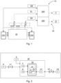
- Fig.1 shows a schematic view on a concept, or in other words system, for wrapping a black box module 30.
- a non-MTP module 20 bus signals SB and material signals SM to a wrapper unit 10.
- the non-MTP module 20 is a physical module of a process plant, wherein the logic signals SL comprise information of logic connections and/or functions of the non-MTP module 20 from logic signal output 21 of the non-MTP module 20, wherein the bus signals SB comprise information of outputs of a fieldbus 22 of the non-MTP module 20, wherein the material signals SM comprise information of material connections 23a, 23b (material input 23a, material output 23b) of the non-MTP module 20.
- the wrapper unit 10 is configured to convert the bus signals SB to open platform communication identifier architecture, OPC UA, nodes 12.
- the wrapper unit 10 is further configured to determine an MTP interface 11 using the logic signals SL and the material signals SM.
- the wrapper unit 10 is further configured to determining a MTP conform digital black box module 30, using OPC UA nodes 12 and the MTP interface 11.
- the MTP interface 11 is determined using a function module 200, wherein the function module 200 is a software description of a module type and is further described in fig 5 .
- the bus signals may be received by the wrapper unit 10 over a physical connection, wherein the fieldbus 22 of the non-MTP module 20 is connected to a controller 300, for example controller AC800M based on 800xA.
- a controller 300 for example controller AC800M based on 800xA.
- the software System 800xA 6.1.1 comprises an orchestration designer that can be used to automatically import MTP-based modules into system 800xA.
- Fig. 2 shows a black box module 30 used in process automation.
- the black box module 30 comprises a first input 11 and a second input 12, as well as a first output O1.
- the user in particular an automation engineer, selects the black box module 30 like any other MTP compliant module and connects the signals of the black box module 30 with external signals.
- a third input 13 is connected to the first input 11 of the black box module 30.
- a fourth input 14 is input into a first valve V1, wherein the output of the first valve 1 is connected with the second input 12 of the black box module 30.
- the first output O1 of the black box module 30 is connected to a second valve V2.
- the output of the second valve V2 is connected to a second output O2.
- the connections can be signal type or material type.
- the third input 13 is a control signal, wherein the fourth input 14 indicates material flow.
- Fig. 3 shows a single tag data object 50, referred to as DataAssembly.
- the new DataAssembly describes the parameters and signals of the black box module 30 in the wrapper unit 10. For each parameter or signal, a new attribute is defined in the "BlackBox" DataAssembly.
- Fig. 4 shows a multi tag data object 50, referred to as DataAssembly.
- the parameters are grouped to the DataAssemblies automatically or by a user.
- the grouping of the parameters gets more complex as the parameters might need indexes (e.g. similar to an array) or the user directly assigns the different parameters to the different tags.
- an algorithm might need to make sure that each type gets the same number and types of parameters as otherwise it cannot be mapped to one type.
- a naming syntax is helpful.
- Fig. 5 shows the content of a function module 200, also referred to as virtual PEA.
- the function module 200 is a software description of a module type. Broadly speaking, the function module 200 serves as a control software configuration for a module of a modular plant, specifying parameters for the said module that are not specific to any target system, such as default parameters.
- the function module 200, serving as the control software configuration is provided as a controller-agnostic configuration file, in other words a target-system-independent configuration file - in one example a generic MTP- for subsequent binding of controller software instantiated according to the controller-agnostic configuration file to a hardware controller of the said module when the said module is integrated into a target system during plant engineering.
- the module 200 contains only the description of the functionality which the target system should contain.
- the function module 200 may contain the same information as the module type, in addition to information concerning the logic that is executed inside the states of the services (application 214 in Figure 2 ).
- the application 212 includes the states executed in the overarching state machine. Only the state machine is externally visible.
- the states are defined as extended cause-and-effect matrices, as for the module type.
- the application 214 optionally also contains logic that is predetermined to be executable independently of the state machines.
- logic that is predetermined to be executable independently of the state machines includes opening a release valve in response pressure in a vessel becoming too high, and opening a release valve to flare in response to too much pressure in a gas pipeline. This kind of logic has to be executed always and independently of the services and the (specifics of the) state-machine controlling the service. Further such examples will be apparent to the skilled reader and are encompassed by this disclosure, which should not be taken as limiting to any one such example.
- This enables the function module 200 to be portable to different kinds of target systems, because the application 214 that should be executed within the states is not yet bound to any target system.
- the parameters may further specify communications for a target module.
- All the above-described parameter types are typically exposed as OPC UA variables by the OPC UA server of the module. Since the OPC UA Server does not exist in the function module 900, and is only later added to the function module instance, the engineer can set default values to the parameters. Those can be (i) subsequently changed during plant engineering, (ii) provided by the actual OPC UA server of the assigned target system, or (iii) set for every state of the state machines or for every service or module wide (i.e. only one parameter value is given that is used for all operating states).
- the function module 200 specifies one or more of the following for the target module: (i) one or more parameters 206, (ii) one or more variables 208, (iii) one or more views 210; (iv) one or more state machines 212; (v) one or more applications 214; (vi) one or more events 916; (vii) one or more methods 204; (viii) one or more signal references 202; (ix) one or more signal outputs 218.
- the function module 200 thus provides for automation of PEAs that do not have an embedded controller and OPC UA server.
- the automation of the function module 200 can be carried out in a central or distributed control system and it is possible to have several function modules 200 on one controller.
- the function module 200 decouples the control application software from the controller and input/output hardware of a PEA. Instead of binding the control application software to hardware as a controller, input and output hardware design may be performed in later steps.
- the software description may be exported as the function module 200 into a controller-agnostic (in other words hardware-independent) MTP.
- the function module 200 can then be assigned to a controller and input/output signals can be matched.
- the concept of the function module comprises a virtual definition of the PEA described as target system independent MTP and an information of a virtual PEA, which includes parameters, variables, view, state machines, applications, events, methods, signal references, signal outputs.
- Fig. 6 shows a schematic view of a method for non-MTP module integration, comprising the following steps: Receiving S10, by a wrapper unit 10, logic signals SL, bus signals SB and material signals SM from a non-MTP module 20, wherein the non-MTP module 20 is a physical module of a process plant, wherein the logic signals SL comprise information of logic connections and/or functions of the non-MTP module 20, wherein the bus signals SB comprise information of outputs of a fieldbus 22 of the non-MTP module 20, wherein the material signals SM comprise information of material connections 23a, 23b of the non-MTP module 20. Converting S20, by the wrapper unit 10, the bus signals SB to open platform communication identifier architecture, OPC UA, nodes 12.
Landscapes
- Engineering & Computer Science (AREA)
- Theoretical Computer Science (AREA)
- General Engineering & Computer Science (AREA)
- Physics & Mathematics (AREA)
- General Physics & Mathematics (AREA)
- Software Systems (AREA)
- Computer Hardware Design (AREA)
- Programmable Controllers (AREA)
Abstract
Description
- The present disclosure relates to the field of module type package, MTP, in process plant engineering, in particular in non-MTP module integration.
- The concepts around module type package, MTP, and modular automation systems describe how process plants can be built and engineered in a more modular way, with the goal to simplify process plant engineering and life cycle management in the future. Nevertheless, there are still packages used that are not MTP-compliant and are therefore integrated in a conventional fashion.
- Modular plants are gradually becoming more and more established, and the community agrees to the miscellaneous benefits provided, not only with respect to development cost but also with respect to time and material efforts. As a standardized methodology the MTP approach therefore creates the framework for interoperability between modules and orchestration system.
- Furthermore, the function module, FM, concept is evolving, which can be used to develop plants in a modular fashion, but without having to stick completely to the MTP standard. If 3rd-party modules that are not MTP-compliant should be integrated, the conventional methods have to be used, which are quite manual and thus time-consuming.
- Thus, there is a need for a method of improved integration of non-MTP modules in modular process automation.
- The present invention is defined by the subject-matter of the independent claims. Additional features of the invention are presented in the dependent claims.
- According to an aspect of the invention, a method for non-MTP module integration comprises the following steps. Receiving, by a wrapper unit, logic signals, bus signals and material signals from a non-MTP module, wherein the non-MTP module is a physical module of a process plant, wherein the logic signals comprise information of logic connections and/or functions of the non-MTP module, wherein the bus signals comprise information of outputs of a fieldbus of the non-MTP module, wherein the material signals comprise information of material connections of the non-MTP module. Converting, by the wrapper unit, the bus signals to open platform communication identifier architecture, OPC UA, nodes. Determining, by the wrapper unit, an MTP interface using the logic signals and the material signals. Determining, by the wrapper unit, a MTP conform digital black box module, using OPC UA nodes and the MTP interface.
- Preferably, the method is a computer-implemented method.
- The term "non-MTP module" as used herein, relates to a physical module of a process plant that is not compliant to the MTP technology. The MTP technology creates a framework for interoperability between modules and an orchestration system and enables process plants to be built up and engineered in a more modular way with the goal of simplifying process plant engineering and life cycle management. Thus, the non-MTP module cannot be directly used by a MTP based process automation software. Preferably, the non-MTP module is a 3rd party module.
- The term "black box module", as used herein, relates to a digital module, that is also referred to as process equipment assembly, PEA, that is MTP conform, or in other words is compliant to the MTP technology. The digital module is also referred to as process equipment assembly, PEA, which is a prefabricated and well-tested module that can be assembled in different combinations in a process automation software to realize a target system, in particular a process plant. The black box module thus can be directly used by an MTP based process automation software. In other words, the black box module behaves identical to a usual digital MTP module in the process automation software, where it is in particular selected out of a plurality of available MTP modules, parametrized and integrated into a design of a process plant.
- The term "wrapper unit", as used herein, is a system that is used to transform a non-MTP module, using software and conventional bus infrastructure, into an MTP compliant module/PEA. The wrapper interfaces the conventional bus interface of the non-MTP compliant module and integrates the signals in a control software. Furthermore, the wrapper module uses software to convert the non-MTP signals of the non-MTP modules into signals that are compliant to MTP.
- The term "OPC UA nodes", as used herein, are variables, objects and methods published by an OPC UA server, which can be consumed by on OPC UA client.
- Preferably, receiving the logic signals comprises parsing, by the wrapper unit, the logic signals from a signal list, for example in form of an XML file, of the non-MTP module. Preferably, receiving the bus signals comprises parsing, by the wrapper unit, the bus signals from a specification, for example in form of an XML file, of the non-MTP module. The bus signals preferably comprise a memory address and a respective data value stored in the memory at the memory address. Alternatively, the wrapper unit comprises a fieldbus adapter that can be directly connected to a fieldbus of the non-MTP module, wherein the fieldbus adapter is configured to read the bus signals and provide preferably the bus signals to an OPC UA server of the wrapper unit that converts the bus signals to OPC UA nodes. In other words, the non-MTP module is physically connected to the wrapper unit. The wrapper unit could for example be an a controller, in particular a programmable logic controller, PLC, for example the AC800M controller. The physical connection to the controller is done using the fieldbus that is provided with the non-MTP module. The physical connection is simply established by connecting the non-MTP module, using the needed control interface, CI, (card), to the controller. After the physical connection, the signals and parameters delivered on the fieldbus are described using logical names in the controller. Where necessary, control diagrams (e.g. FBD) or programs (e.g. ST, structured text) for reading and interpreting or writing to a signal or parameter are used. When this mapping is done, the controller can already expose the parameters and signals as OPC UA nodes. In other words, the wrapper unit wraps the physical layer uses the fieldbus adapter to the south-side of the wrapper unit and exposing the parameters through an OPC UA server to the north of the wrapper unit. Thus, when no specification of the non-MTP module is available, the non-MTP module is connected to the wrapper unit one time to analyse the bus signals, in particular at which memory address of the memory of the non-MTP module the desired bus signals is stored.
- Preferably, receiving the material signals comprises parsing, by the wrapper unit, the material signals from a piping and instrumentation diagram, P&ID, for example in form of an XML file, in particular a DEXPI file, of the non-MTP module. The material signals preferably comprise physical process input and outputs of the non-MTP module.
- In other words, converting the bus signals relates to wrapping the physical layer from any fieldbus, e.g. Profibus, Profinet, to OPC UA nodes.
- Determining the black box model further comprises generating the MTP for the black box model. The MTP includes for example a customized DataAssembly that is specific for the black-box module. The OPC UA nodes referenced in the DataAssembly point to the OPC UA nodes of the wrapper unit that wraps the non-MTP module. Once an MTP is generated, the black-box module looks like, behaves like and can be used just like a function module in the automation software. That means it can either be integrated into another function module or it can be used directly in the topology for the process plant.
- Consequently, non-MTP modules are wrapped using a wrapping unit in order to enable the non-MTP modules for automatic import, as well. This should show benefits, whenever a module type is used at least twice.
- Preferably, conventional bus systems are used to connect the non-MTP module to an MTP-compliant controller, the controller can map those signals to OPC UA and the parameters of the packages can be described as a user-defined DataAssembly in the MTP. This method is useful whenever a black-box module is used several times within a plant, project, or customer company. An example would be the McLyzer module from McPhy that is used often for hydrogen plants.
- Consequently, the method for non-MTP module integration allows to use a non-MTP module in a module type package based automation software with improved efficiency.
- In a preferred embodiment, determining the MTP interface comprises the following steps. Determining, by the wrapper unit, a new data object using the logic signals, wherein the data object describes parameters and signals of the black box model in an MTP conform way. Determining, by the wrapper unit, an HMI definition using the material signals and the logic signals. Determining the MTP interface using the data object and the HMI definition.
- In order to provide a MTP package format, the black box module needs to comprise information about the signals and their function as well as the material that is input and output of the non-MTP module.
- In a preferred embodiment, the data object is determined using an MTP information model, wrapping the logic signals of the non-MTP module into OPC UA nodes.
- The MTP information model preferably comprises a DataAssembly, wherein the wrapper unit is MTP-compliant but implements additional functionality that is specific for the non-MTP module. The DataAssembly wraps all logic signals (parameters and signals of the non-MTP module) and exposes those as OPC UA nodes of the OPC server of the wrapper unit.
- A tag editor is preferably used to generate a module specific DataAssembly. For smaller packages, a single tag for the entire module should be sufficient. Further preferably, the black-box module is wrapped into a DataAssembly called "BlackBox". Then the attributes of the DataAssembly are defined for example "Power", "Current", "Voltage" and "NewAttributeN". These attributes are the same as the attributes defined for the wrapper unit fieldbus mapping and can be generated from the wrapper unit configuration automatically.
- In a preferred embodiment, determining the data object comprises determining a service frame to execute the black-box module.
- In other words, in particular based on user input, a frame for the mirroring function module for the black-box modules, is defined. A symbol for the black-box module is added to the function module. Additionally, a frame program for a service to run the black-box module is defined.
- For the service, the parameters of the black-box module are mapped to services parameters. The service parameters can, depending on the function in the black-box module, be mapped to procedure parameters, report parameters or configuration parameters. Those parameters don't have to be described within the DataAssembly for the module.
- In a preferred embodiment, determining the service frame comprises generating a state machine. Preferably, the state machine is a state machine as standardized in VDI2658 part 4, which is the definition of the service interface for the MTP. That means, the state-machine is always the same and only the state have to be filled with logic.
- Preferably, a frame for a single service to execute the black-box module can be generated. A simplified state machine is generated, wherein parameters of the black-box module that needs to be configured for the execution of the module are added as service parameters. If required, the alarms and implemented control logic for the service are added, automatically or by a user, in the in the same way as for normal function modules.
- In a preferred embodiment, the bus signals comprise signals from a fieldbus of the non-MTP module.
- Preferably, the fieldbus, comprises a profibus, a profinet or the like.
- If the bus signals comprise data points with a data address, the wrapper unit can directly map the information to OPC UA.
- If the bus signals comprise non-MTP OPA UA signals. Such information is relatively complex to convert.
- In a preferred embodiment, the data object is split into a plurality of data objects
- Instead of using a single tag, the black box module can be split into several tags, e.g., if there are similar or same parts used often within a single instance.
- In other words, a new DataAssembly SystemUnitClass is defined in the MTP. This is derived from the DataAssembly SystemUnitClass to be able to add an instance of it to the instance hierarchy in the MTP. This SystemUnitClass shall describe all parameters and signals of the black-box module. Later, the DataAssembly can be instantiated in the MTP to defined where to find the corresponding parameters on the OPC UA server. wherein the data object comprises at least one attribute for each parameter or signal; wherein the at least one attribute is determined using the physical connections.
- In a preferred embodiment, determining the HMI definition comprises the following steps. Generating an HMI symbol for the non-MTP module. Mapping the bus signals, and the logic signals to the generated HMI symbol.
- The symbol preferably includes all material signals (for example pipes) and all logic signals (signals and parameters).
- The symbol is preferably created automatically from a description of the black-box module.
- It is important that the material signals (for example the pipe connection) and the logical signals are attached to the HMI symbol in an HMI editor of the wrapping unit. This information is later used when it is either nested into another function module or instantiated in a topology designer of the automation software.
- In a preferred embodiment, the mapping of the logic signals comprises determining a combined logic signal, combining a plurality of logic signals.
- Especially non-MTP modules with many status information values, might result in many outputs for the wrapping unit. If the outputs are taken as they are and there are a lot of status information values, the HMI symbol gets quite big but therefore it's easy for the user (automation engineer) to connect. Thus, the user could mark which logic signals he wants to group together. This combined logic signal is then taken as a structured signal. A new structured data type is added. The MTP reflects this data type, as e.g., AttributeList or DataAssembly. The determination of a combined logic signal is alternatively automatically performed. Preferably, automatic grouping is performed by identifying patterns within a module and afterwards do a pattern matching of the equipment of the module. For every occurrence of a pattern, a group could be created. Another way of automatic implementation comprises identifying buffers in the process, e.g., storage vessels, and traverse upstream and downstream. Every upstream and every downstream path could be an own group.
- According to an aspect of the invention a wrapper unit for non-MTP module integration, is configured for: Receiving logic signals, bus signals and material signals from a non-MTP module, wherein the non-MTP module is a physical module of a process plant, wherein the logic signals comprise information of logic connections and/or functions of the non-MTP module, wherein the bus signals comprise information of outputs of a fieldbus of the non-MTP module, wherein the material signals comprise information of material connections. Converting the bus signals to OPC UA nodes. Determining an MTP interface using the logic signals and the physical connection signals. Determining a MTP conform digital black box module, using OPC UA nodes and the MTP interface.
- According to an aspect of the invention a black box model, as determined with the method for non-MTP module integration, as described herein, is used in an MTP-compliant control system.
- The subject matter of the invention will be explained in more detail in the following text with reference to preferred exemplary embodiments, which are illustrated in the attached drawings, in which:
- Exemplary embodiments of the invention will be described in the following with reference to the accompanying drawings:
- Fig.1
- shows a schematic view on a concept for wrapping a black box module;
- Fig. 2
- shows a black box module used in process automation;
- Fig. 3
- shows a single tag data object;
- Fig. 4
- shows a multi tag data object;
- Fig. 5
- shows a schematic view of a function module; and
- Fig. 6
- shows a schematic view of a method for non-MTP module integration.
- The reference symbols used in the drawings, and their meanings, are listed in summary form in the list of reference symbols. In principle, identical assembly parts are provided with the same reference symbols in the figures.
- Preferably, the functional modules and/or the configuration mechanisms are implemented as programmed software modules or procedures, respectively; however, one skilled in the art will understand that the functional modules and/or the configuration mechanisms can be implemented fully or assembly partially in hardware.
-
Fig.1 shows a schematic view on a concept, or in other words system, for wrapping ablack box module 30. Anon-MTP module 20, bus signals SB and material signals SM to awrapper unit 10. Thenon-MTP module 20 is a physical module of a process plant, wherein the logic signals SL comprise information of logic connections and/or functions of thenon-MTP module 20 fromlogic signal output 21 of thenon-MTP module 20, wherein the bus signals SB comprise information of outputs of afieldbus 22 of thenon-MTP module 20, wherein the material signals SM comprise information ofmaterial connections material input 23a,material output 23b) of thenon-MTP module 20. Thewrapper unit 10 is configured to convert the bus signals SB to open platform communication identifier architecture, OPC UA,nodes 12. Thewrapper unit 10 is further configured to determine anMTP interface 11 using the logic signals SL and the material signals SM. Thewrapper unit 10 is further configured to determining a MTP conform digitalblack box module 30, usingOPC UA nodes 12 and theMTP interface 11. - The
MTP interface 11 is determined using afunction module 200, wherein thefunction module 200 is a software description of a module type and is further described infig 5 . - The bus signals may be received by the
wrapper unit 10 over a physical connection, wherein thefieldbus 22 of thenon-MTP module 20 is connected to acontroller 300, for example controller AC800M based on 800xA. For example the software System 800xA 6.1.1 comprises an orchestration designer that can be used to automatically import MTP-based modules into system 800xA. -
Fig. 2 shows ablack box module 30 used in process automation. Theblack box module 30 comprises afirst input 11 and asecond input 12, as well as a first output O1. In the orchestration designer of the automation software, the user, in particular an automation engineer, selects theblack box module 30 like any other MTP compliant module and connects the signals of theblack box module 30 with external signals. In this case, athird input 13 is connected to thefirst input 11 of theblack box module 30. Further, afourth input 14 is input into a first valve V1, wherein the output of thefirst valve 1 is connected with thesecond input 12 of theblack box module 30. Further, the first output O1 of theblack box module 30 is connected to a second valve V2. The output of the second valve V2 is connected to a second output O2. The connections can be signal type or material type. For example, thethird input 13 is a control signal, wherein thefourth input 14 indicates material flow. -
Fig. 3 shows a singletag data object 50, referred to as DataAssembly. The new DataAssembly describes the parameters and signals of theblack box module 30 in thewrapper unit 10. For each parameter or signal, a new attribute is defined in the "BlackBox" DataAssembly. -
Fig. 4 shows a multi tag data object 50, referred to as DataAssembly. The parameters are grouped to the DataAssemblies automatically or by a user. In case one DataAssembly type is used more than once (here 'StackCDT'), the grouping of the parameters gets more complex as the parameters might need indexes (e.g. similar to an array) or the user directly assigns the different parameters to the different tags. In this case an algorithm might need to make sure that each type gets the same number and types of parameters as otherwise it cannot be mapped to one type. Here, a naming syntax is helpful. -
Fig. 5 shows the content of afunction module 200, also referred to as virtual PEA. Thefunction module 200 is a software description of a module type. Broadly speaking, thefunction module 200 serves as a control software configuration for a module of a modular plant, specifying parameters for the said module that are not specific to any target system, such as default parameters. Thefunction module 200, serving as the control software configuration, is provided as a controller-agnostic configuration file, in other words a target-system-independent configuration file - in one example a generic MTP- for subsequent binding of controller software instantiated according to the controller-agnostic configuration file to a hardware controller of the said module when the said module is integrated into a target system during plant engineering. - More particularly, instead of having a binding to a specific target system, the
module 200 contains only the description of the functionality which the target system should contain. For example, thefunction module 200 may contain the same information as the module type, in addition to information concerning the logic that is executed inside the states of the services (application 214 inFigure 2 ). Theapplication 212 includes the states executed in the overarching state machine. Only the state machine is externally visible. The states are defined as extended cause-and-effect matrices, as for the module type. - The
application 214 optionally also contains logic that is predetermined to be executable independently of the state machines. In one example for equipment protection, if for example a valve is closed, all succeeding pumps have to be stopped to prevent them from running dry. Further examples of logic that is predetermined to be executable independently of the state machines includes opening a release valve in response pressure in a vessel becoming too high, and opening a release valve to flare in response to too much pressure in a gas pipeline. This kind of logic has to be executed always and independently of the services and the (specifics of the) state-machine controlling the service. Further such examples will be apparent to the skilled reader and are encompassed by this disclosure, which should not be taken as limiting to any one such example. This enables thefunction module 200 to be portable to different kinds of target systems, because theapplication 214 that should be executed within the states is not yet bound to any target system. The parameters may further specify communications for a target module. - For every control equipment (sensor, valve, etc.) used in the module, a set of parameters is defined. There may be different kinds of parameters for the module that are not specific to any target system, as in the following non-limiting examples. Further such examples will be apparent to the skilled reader and are encompassed by this disclosure, which should not be taken as limiting to any one such example.
- A sensor for example has a range, meaning it can measure 1 ... 10 bar. These parameters depend on the final hardware used - a sensor cannot measure outside its measuring range. Those parameters are set once, when later (during plant engineering) the target system and the devices are assigned, and remain constant. When in different instances of the function module different sensor types are used to measure the pressure, this parameter is later adapted (e.g. during plant engineering) when the target hardware and devices are assigned to the function module instance (as an instance of a software controller instantiated according to a controller-agnostic configuration file). The block controlling a sensor can specify limits. A limit is a software-defined number that must be inside the measuring range. It can be used to raise alarms if the measure value is over/under a defined limit. These limits can be parameterized everywhere in the application. In one non-limiting example, to provide parameters that are not specific to any target system, default limits may be set, and later changed, if necessary. A typical case is that, during startup, the limits are set broader to avoid alarm floods and once the module is running in steady-state, the limits are narrowed down to keep the process in an optimal operating state.
- A service might have parameters for configuration of how it should perform, e.g., the process value is measured inside the module or comes from somewhere else. The configuration parameters may show which of the sources is used. In one non-limiting example of a parameter that is not specific to any target system, a default source may be specified, in order to provide a defined state for the case in which no further parameterization is performed. Alternatively, the parameter may be forgotten during adaptation. In another non-limiting example, default service parameters may be given for setpoints, e.g., the fill service should fill the vessel to 50%.
- All the above-described parameter types are typically exposed as OPC UA variables by the OPC UA server of the module. Since the OPC UA Server does not exist in the function module 900, and is only later added to the function module instance, the engineer can set default values to the parameters. Those can be (i) subsequently changed during plant engineering, (ii) provided by the actual OPC UA server of the assigned target system, or (iii) set for every state of the state machines or for every service or module wide (i.e. only one parameter value is given that is used for all operating states).
- As shown in
Figure 5 , thefunction module 200, provided as a controller-agnostic configuration file, for example in the form of a generic MTP, specifies one or more of the following for the target module: (i) one ormore parameters 206, (ii) one ormore variables 208, (iii) one ormore views 210; (iv) one ormore state machines 212; (v) one ormore applications 214; (vi) one or more events 916; (vii) one ormore methods 204; (viii) one or more signal references 202; (ix) one or more signal outputs 218. - The
function module 200 thus provides for automation of PEAs that do not have an embedded controller and OPC UA server. The automation of thefunction module 200 can be carried out in a central or distributed control system and it is possible to haveseveral function modules 200 on one controller. Thefunction module 200 decouples the control application software from the controller and input/output hardware of a PEA. Instead of binding the control application software to hardware as a controller, input and output hardware design may be performed in later steps. The software description may be exported as thefunction module 200 into a controller-agnostic (in other words hardware-independent) MTP. During plant engineering, thefunction module 200 can then be assigned to a controller and input/output signals can be matched. Thus, it may also be possible to assignseveral function modules 200 to a single controller and to reuse thefunction module 200 with another vendor or target system later. - The concept of the function module comprises a virtual definition of the PEA described as target system independent MTP and an information of a virtual PEA, which includes parameters, variables, view, state machines, applications, events, methods, signal references, signal outputs.
-
Fig. 6 shows a schematic view of a method for non-MTP module integration, comprising the following steps: Receiving S10, by awrapper unit 10, logic signals SL, bus signals SB and material signals SM from anon-MTP module 20, wherein thenon-MTP module 20 is a physical module of a process plant, wherein the logic signals SL comprise information of logic connections and/or functions of thenon-MTP module 20, wherein the bus signals SB comprise information of outputs of afieldbus 22 of thenon-MTP module 20, wherein the material signals SM comprise information ofmaterial connections non-MTP module 20. Converting S20, by thewrapper unit 10, the bus signals SB to open platform communication identifier architecture, OPC UA,nodes 12. Determining S30, by thewrapper unit 10, anMTP interface 11 using the logic signals SL and the material signals SM. Determining S40, by thewrapper unit 10, a MTP conform digitalblack box module 30, usingOPC UA nodes 12 and theMTP interface 11. -
- 10
- wrapper unit
- 11
- MTP interface
- 12
- OPC UA nodes
- 20
- non-MTP module
- 21
- logic signal output
- 22
- fieldbus
- 23a
- material input
- 23b
- material output
- 30
- black box module
- 40
- HMI definitions
- 50
- data object
- 200
- function module
- 202
- signal references
- 204
- methods
- 206
- parameters
- 208
- variables
- 210
- views
- 212
- state machines
- 214
- application
- 216
- events
- 218
- signal outputs
- 300
- controller
- SM
- material signal
- SL
- logic signal
- SB
- bus signal
- 11
- first input
- 12
- second input
- 13
- third input
- 14
- fourth input
- O1
- first output
- O2
- second output
- V1
- first valve
- V2
- second valve
- S10-S40
- method steps
Claims (14)
- Method for non-MTP module integration, comprising the steps:receiving (S10), by a wrapper unit (10), logic signals (SL), bus signals (SB) and material signals (SM) from a non-MTP module (20), wherein the non-MTP module (20) is a physical module of a process plant, wherein the logic signals (SL) comprise information of logic connections and/or functions of the non-MTP module (20), wherein the bus signals (SB) comprise information of outputs of a fieldbus (22) of the non-MTP module (20), wherein the material signals (SM) comprise information of material connections (23a, 23b) of the non-MTP module (20);converting (S20), by the wrapper unit (10), the bus signals (SB) to open platform communication identifier architecture, OPC UA, nodes (12);determining (S30), by the wrapper unit (10), an MTP interface (11) using the logic signals (SL) and the material signals (SM); anddetermining (S40), by the wrapper unit (10), a MTP conform digital black box module (30), using OPC UA nodes (12) and the MTP interface (11).
- Method of claim 1,
wherein the MTP interface (11) is determined using a function module (200), wherein the function module (200) is a software description of a module type: - Method of any one of the preceding claims,
wherein determining the MTP interface (11) comprises:determining, by the wrapper unit (10), a new data object (50) using the logic signals (SL), wherein the data object (50) describes parameters and signals of the black box model (30) in an MTP conform way;determining, by the wrapper unit (10), a HMI definition (40) using the material signals (SM) and the logic signals (SL);determining the MTP interface (11) using the data object (50) and the HMI definition (40). - Method of claim 3,
wherein the data object (50) is determined using an MTP information model, wrapping the logic signals (SL) of the non-MTP module (30) into OPC UA nodes. - Method of any of the claims 3-4,
wherein determining the data object (50) comprises determining a service frame to execute the black-box module (30). - Method of claim 5,
wherein determining the service frame comprises generating a state machine. - Method of any one of the claims 3-6,
wherein the data object (50) is split into a plurality of data objects - Method of any one of the preceding claims,
wherein the bus signals (SB) comprise signals from a fieldbus (22) of the none-MTP module (30). - Method of any one of the preceding claims,
wherein determining the HMI definition (40) comprises:generating a HMI symbol for the non-MTP module (30);mapping the material signals (SM), and the logic signals (SL) to the generated HMI symbol. - Method of any one of the preceding claims,
wherein the mapping of the logic signals (SL) comprises determining a combined logic signal, combining a plurality of logic signals. - Wrapper unit (10) for non-MTP module integration, configured for:receiving logic signals (SL), bus signals (SB) and material signals (SM) from a non-MTP module (20), wherein the non-MTP module (20) is a physical module of a process plant, wherein the logic signals (SL) comprise information of logic connections and/or functions of the non-MTP module (20), wherein the bus signals (SB) comprise information of outputs of a fieldbus (22) of the non-MTP module (20), wherein the material signals (SM) comprise information of material connections (23a, 23b) of the non-MTP module (20);converting the bus signals (SB) to open platform communication identifier architecture, OPC UA, nodes (12);determining an MTP interface (11) using the logic signals (SL) and the material signals (SM);determining a MTP conform digital black box module (30), using OPC UA nodes (12) and the MTP interface (11).
- A computer program, comprising instructions which, when the program is executed by a computer, cause the computer to carry out the method of claims 1-10.
- A computer-readable data carrier having stored thereon the computer program of claim 12.
- Use of a black box model (30), as determined with the method for non-MTP module (20) integration according to any one of claim 1-10, in an MTP-compliant control system.
Priority Applications (3)
| Application Number | Priority Date | Filing Date | Title |
|---|---|---|---|
| EP22183909.5A EP4303727A1 (en) | 2022-07-08 | 2022-07-08 | Non-mtp module integration |
| CN202310824661.5A CN117370250A (en) | 2022-07-08 | 2023-07-06 | non-MTP module integration |
| US18/348,565 US12436913B2 (en) | 2022-07-08 | 2023-07-07 | Non-MTP module integration |
Applications Claiming Priority (1)
| Application Number | Priority Date | Filing Date | Title |
|---|---|---|---|
| EP22183909.5A EP4303727A1 (en) | 2022-07-08 | 2022-07-08 | Non-mtp module integration |
Publications (1)
| Publication Number | Publication Date |
|---|---|
| EP4303727A1 true EP4303727A1 (en) | 2024-01-10 |
Family
ID=82404327
Family Applications (1)
| Application Number | Title | Priority Date | Filing Date |
|---|---|---|---|
| EP22183909.5A Pending EP4303727A1 (en) | 2022-07-08 | 2022-07-08 | Non-mtp module integration |
Country Status (3)
| Country | Link |
|---|---|
| US (1) | US12436913B2 (en) |
| EP (1) | EP4303727A1 (en) |
| CN (1) | CN117370250A (en) |
Families Citing this family (1)
| Publication number | Priority date | Publication date | Assignee | Title |
|---|---|---|---|---|
| EP4664273A1 (en) * | 2024-06-12 | 2025-12-17 | Abb Schweiz Ag | Custom library integration into mtp-modular automation engineering |
Family Cites Families (9)
| Publication number | Priority date | Publication date | Assignee | Title |
|---|---|---|---|---|
| DE10253603A1 (en) * | 2002-11-15 | 2004-06-03 | Endress + Hauser Conducta Gesellschaft für Mess- und Regeltechnik mbH + Co. KG | Method for generating software modules for field devices in process automation technology |
| US8332567B2 (en) * | 2006-09-19 | 2012-12-11 | Fisher-Rosemount Systems, Inc. | Apparatus and methods to communicatively couple field devices to controllers in a process control system |
| US9572020B2 (en) * | 2013-09-19 | 2017-02-14 | Honeywell International Inc. | Apparatus and method supporting wireless communications between devices using different application protocols in industrial control and automation systems |
| BE1026842B1 (en) * | 2018-12-06 | 2020-07-06 | Phoenix Contact Gmbh & Co | Integration of several system modules, each with at least one process engineering unit, to form a modular overall system |
| US11635980B2 (en) * | 2019-09-20 | 2023-04-25 | Fisher-Rosemount Systems, Inc. | Modular process control system |
| US11347208B2 (en) * | 2020-04-29 | 2022-05-31 | Fisher-Rosemount Systems, Inc. | Ethernet I/O card scanner |
| EP3929679A1 (en) * | 2020-06-23 | 2021-12-29 | ABB Schweiz AG | Engineering system for orchestration of an industrial plant |
| DE102020130022A1 (en) * | 2020-11-13 | 2022-05-19 | Festo Se & Co. Kg | Checking the compatibility of a process module to be newly integrated in an automation system |
| US20220253040A1 (en) * | 2021-02-10 | 2022-08-11 | Yokogawa Electric Corporation | Methods, systems and computer program products for generating and implementing engineering data within process control systems |
-
2022
- 2022-07-08 EP EP22183909.5A patent/EP4303727A1/en active Pending
-
2023
- 2023-07-06 CN CN202310824661.5A patent/CN117370250A/en active Pending
- 2023-07-07 US US18/348,565 patent/US12436913B2/en active Active
Non-Patent Citations (2)
| Title |
|---|
| GMBH SEMODIA: "Semodia MTP-Box", 18 May 2022 (2022-05-18), pages 1 - 6, XP093015002, Retrieved from the Internet <URL:https://web.archive.org/web/20220518235737/https://semodia.com/en/products/mtp-box/> [retrieved on 20230118] * |
| HOERNICKE MARIO ET AL: "Automation architecture and engineering for modular process plants - approach and industrial pilot application", IFAC-PAPERSONLINE, vol. 53, no. 2, 14 April 2021 (2021-04-14), DE, pages 8255 - 8260, XP093015012, ISSN: 2405-8963, DOI: 10.1016/j.ifacol.2020.12.1966 * |
Also Published As
| Publication number | Publication date |
|---|---|
| US20240012783A1 (en) | 2024-01-11 |
| US12436913B2 (en) | 2025-10-07 |
| CN117370250A (en) | 2024-01-09 |
Similar Documents
| Publication | Publication Date | Title |
|---|---|---|
| US12216456B2 (en) | Configuration of a modular plant | |
| US7822495B2 (en) | Custom function blocks for use with process control systems | |
| US5828851A (en) | Process control system using standard protocol control of standard devices and nonstandard devices | |
| US8015547B2 (en) | Reconfigurable, hierarchical component-based architecture and framework and methods for rapidly developing sensor device-enabling software applications | |
| US8538719B2 (en) | Method for testing device descriptions for field devices of automation technology | |
| Zoitl et al. | IEC 61499 architecture for distributed automation: The ‘glass half full’view | |
| US8234357B2 (en) | Method for servicing field devices of process automation technology utilizing a device-independent operating program | |
| US20080313629A1 (en) | Method for installation of objects for a component-based management system for field devices of automation technology | |
| EP4348361B1 (en) | Computer-implemented method and orchestration system to orchestrate configurations of simulations based on digital twin models of modular plants | |
| US12321727B2 (en) | Data interaction method, apparatus and system for AI inference device and automation controller | |
| CN101784965A (en) | Method for controlling field devices in automation technology | |
| US8381165B2 (en) | Method for producing software modules for field devices of process automation technology | |
| US8019724B2 (en) | Software framework for evolving specifications in process control system | |
| US12436913B2 (en) | Non-MTP module integration | |
| US12140936B2 (en) | Configuring modular industrial plants | |
| CN116324652A (en) | Mixing operations of production units in a mixing plant | |
| CN112578305A (en) | Aircraft power supply characteristic testing method and system, electronic equipment and storage medium | |
| US8050784B2 (en) | Integrated programmer reference for industrial control device data | |
| US20240256479A1 (en) | Function Module Interface in an Industrial Process Environment | |
| CN119917089A (en) | A multi-layer packaging method |
Legal Events
| Date | Code | Title | Description |
|---|---|---|---|
| PUAI | Public reference made under article 153(3) epc to a published international application that has entered the european phase |
Free format text: ORIGINAL CODE: 0009012 |
|
| STAA | Information on the status of an ep patent application or granted ep patent |
Free format text: STATUS: THE APPLICATION HAS BEEN PUBLISHED |
|
| AK | Designated contracting states |
Kind code of ref document: A1 Designated state(s): AL AT BE BG CH CY CZ DE DK EE ES FI FR GB GR HR HU IE IS IT LI LT LU LV MC MK MT NL NO PL PT RO RS SE SI SK SM TR |
|
| STAA | Information on the status of an ep patent application or granted ep patent |
Free format text: STATUS: REQUEST FOR EXAMINATION WAS MADE |
|
| 17P | Request for examination filed |
Effective date: 20240625 |
|
| RBV | Designated contracting states (corrected) |
Designated state(s): AL AT BE BG CH CY CZ DE DK EE ES FI FR GB GR HR HU IE IS IT LI LT LU LV MC MK MT NL NO PL PT RO RS SE SI SK SM TR |