EP4303569A1 - Determination device - Google Patents
Determination device Download PDFInfo
- Publication number
- EP4303569A1 EP4303569A1 EP22791742.4A EP22791742A EP4303569A1 EP 4303569 A1 EP4303569 A1 EP 4303569A1 EP 22791742 A EP22791742 A EP 22791742A EP 4303569 A1 EP4303569 A1 EP 4303569A1
- Authority
- EP
- European Patent Office
- Prior art keywords
- fluorescence
- determination device
- determiner
- image
- predetermined
- Prior art date
- Legal status (The legal status is an assumption and is not a legal conclusion. Google has not performed a legal analysis and makes no representation as to the accuracy of the status listed.)
- Pending
Links
Images




Classifications
-
- G—PHYSICS
- G01—MEASURING; TESTING
- G01N—INVESTIGATING OR ANALYSING MATERIALS BY DETERMINING THEIR CHEMICAL OR PHYSICAL PROPERTIES
- G01N21/00—Investigating or analysing materials by the use of optical means, i.e. using sub-millimetre waves, infrared, visible or ultraviolet light
- G01N21/62—Systems in which the material investigated is excited whereby it emits light or causes a change in wavelength of the incident light
- G01N21/63—Systems in which the material investigated is excited whereby it emits light or causes a change in wavelength of the incident light optically excited
- G01N21/64—Fluorescence; Phosphorescence
- G01N21/645—Specially adapted constructive features of fluorimeters
- G01N21/6456—Spatial resolved fluorescence measurements; Imaging
-
- G—PHYSICS
- G01—MEASURING; TESTING
- G01N—INVESTIGATING OR ANALYSING MATERIALS BY DETERMINING THEIR CHEMICAL OR PHYSICAL PROPERTIES
- G01N21/00—Investigating or analysing materials by the use of optical means, i.e. using sub-millimetre waves, infrared, visible or ultraviolet light
- G01N21/62—Systems in which the material investigated is excited whereby it emits light or causes a change in wavelength of the incident light
- G01N21/63—Systems in which the material investigated is excited whereby it emits light or causes a change in wavelength of the incident light optically excited
- G01N21/64—Fluorescence; Phosphorescence
- G01N21/6486—Measuring fluorescence of biological material, e.g. DNA, RNA, cells
-
- G—PHYSICS
- G01—MEASURING; TESTING
- G01N—INVESTIGATING OR ANALYSING MATERIALS BY DETERMINING THEIR CHEMICAL OR PHYSICAL PROPERTIES
- G01N33/00—Investigating or analysing materials by specific methods not covered by groups G01N1/00 - G01N31/00
- G01N33/02—Food
-
- G—PHYSICS
- G01—MEASURING; TESTING
- G01N—INVESTIGATING OR ANALYSING MATERIALS BY DETERMINING THEIR CHEMICAL OR PHYSICAL PROPERTIES
- G01N21/00—Investigating or analysing materials by the use of optical means, i.e. using sub-millimetre waves, infrared, visible or ultraviolet light
- G01N21/62—Systems in which the material investigated is excited whereby it emits light or causes a change in wavelength of the incident light
- G01N21/63—Systems in which the material investigated is excited whereby it emits light or causes a change in wavelength of the incident light optically excited
- G01N21/64—Fluorescence; Phosphorescence
- G01N21/645—Specially adapted constructive features of fluorimeters
- G01N2021/6463—Optics
- G01N2021/6471—Special filters, filter wheel
-
- G—PHYSICS
- G01—MEASURING; TESTING
- G01N—INVESTIGATING OR ANALYSING MATERIALS BY DETERMINING THEIR CHEMICAL OR PHYSICAL PROPERTIES
- G01N21/00—Investigating or analysing materials by the use of optical means, i.e. using sub-millimetre waves, infrared, visible or ultraviolet light
- G01N21/84—Systems specially adapted for particular applications
- G01N2021/8466—Investigation of vegetal material, e.g. leaves, plants, fruits
-
- G—PHYSICS
- G01—MEASURING; TESTING
- G01N—INVESTIGATING OR ANALYSING MATERIALS BY DETERMINING THEIR CHEMICAL OR PHYSICAL PROPERTIES
- G01N21/00—Investigating or analysing materials by the use of optical means, i.e. using sub-millimetre waves, infrared, visible or ultraviolet light
- G01N21/62—Systems in which the material investigated is excited whereby it emits light or causes a change in wavelength of the incident light
- G01N21/63—Systems in which the material investigated is excited whereby it emits light or causes a change in wavelength of the incident light optically excited
- G01N21/64—Fluorescence; Phosphorescence
- G01N21/6408—Fluorescence; Phosphorescence with measurement of decay time, time resolved fluorescence
-
- G—PHYSICS
- G01—MEASURING; TESTING
- G01N—INVESTIGATING OR ANALYSING MATERIALS BY DETERMINING THEIR CHEMICAL OR PHYSICAL PROPERTIES
- G01N21/00—Investigating or analysing materials by the use of optical means, i.e. using sub-millimetre waves, infrared, visible or ultraviolet light
- G01N21/84—Systems specially adapted for particular applications
- G01N21/85—Investigating moving fluids or granular solids
-
- G—PHYSICS
- G01—MEASURING; TESTING
- G01N—INVESTIGATING OR ANALYSING MATERIALS BY DETERMINING THEIR CHEMICAL OR PHYSICAL PROPERTIES
- G01N2201/00—Features of devices classified in G01N21/00
- G01N2201/06—Illumination; Optics
- G01N2201/061—Sources
- G01N2201/06146—Multisources for homogeneisation, as well sequential as simultaneous operation
- G01N2201/06153—Multisources for homogeneisation, as well sequential as simultaneous operation the sources being LED's
-
- G—PHYSICS
- G01—MEASURING; TESTING
- G01N—INVESTIGATING OR ANALYSING MATERIALS BY DETERMINING THEIR CHEMICAL OR PHYSICAL PROPERTIES
- G01N2201/00—Features of devices classified in G01N21/00
- G01N2201/08—Optical fibres; light guides
-
- G—PHYSICS
- G01—MEASURING; TESTING
- G01N—INVESTIGATING OR ANALYSING MATERIALS BY DETERMINING THEIR CHEMICAL OR PHYSICAL PROPERTIES
- G01N2201/00—Features of devices classified in G01N21/00
- G01N2201/12—Circuits of general importance; Signal processing
- G01N2201/129—Using chemometrical methods
- G01N2201/1293—Using chemometrical methods resolving multicomponent spectra
-
- G—PHYSICS
- G01—MEASURING; TESTING
- G01N—INVESTIGATING OR ANALYSING MATERIALS BY DETERMINING THEIR CHEMICAL OR PHYSICAL PROPERTIES
- G01N2201/00—Features of devices classified in G01N21/00
- G01N2201/12—Circuits of general importance; Signal processing
- G01N2201/129—Using chemometrical methods
- G01N2201/1296—Using chemometrical methods using neural networks
Definitions
- the present disclosure relates to a determination device.
- a device for determining the degree of freshness/maturity described in Patent Document 1 includes a container, a light source, an optical sensor, and a control unit.
- the container stores fresh food.
- the light source irradiates the fresh food placed in the container with visible light.
- the optical sensor detects the light intensity of a predetermined wavelength region of light reflected from the fresh food irradiated with the visible light.
- the control unit determines the degree of freshness or maturity of the fresh food based on the light intensity of the predetermined wavelength region detected by the optical sensor.
- Patent Document 1 Japanese Unexamined Patent Publication No. 2018-096712
- the device for determining the degree of freshness/maturity described in Patent Document 1 determines only the states of points of the fresh food irradiated with visible light. Thus, if the state of whole fresh food as an object is determined, the accuracy of this determination may decrease.
- a first aspect of the present disclosure is directed to a determination device.
- the determination device includes: an irradiator (10) configured to irradiate an object (A) including a food or a plant with a light; an extractor (20) configured to extract a predetermined fluorescence emission having a predetermined wavelength out of fluorescence emissions generated from a surface of the object (A) irradiated with the light; an imager (30) configured to capture a fluorescence image indicating the predetermined fluorescence emission; and a determiner (60) configured to determine a state of the object (A) based on an index indicating a fluorescence intensity of the fluorescence image.
- the first aspect can reduce a decrease in accuracy of determination of the state of the object (A).
- a second aspect of the present disclosure is an embodiment of the first aspect.
- the determiner (60) determines the state of the object (A) based on the fluorescence image including a plurality of fluorescence images, and the predetermined fluorescence emission indicated by the fluorescence image has a different wavelength for each of the fluorescence images.
- the determiner (60) uses the plurality of fluorescence images to determine the state of the object (A), thereby further improving the determination accuracy.
- a third aspect of the present disclosure is an embodiment of the first or second aspect.
- the determination device includes a scanning mechanism (70) configured to change relative positions of the object (A) and the imager (30) relative to each other.
- the fluorescence image of the entire object (A) can be acquired.
- a fourth aspect of the present disclosure is an embodiment of the first to third aspects.
- the predetermined wavelength is 550 nm or more and 750 nm or less.
- the extractor (20) can extract the predetermined fluorescence emission having a wavelength of 550 nm or more and 750 nm or less.
- a fifth aspect of the present disclosure is an embodiment of any one of the first to fourth aspects.
- the irradiator (10) emits ultraviolet rays.
- ultraviolet rays are emitted from the irradiator (10), and thus a fluorescence emission can be generated from the object (A).
- a sixth aspect of the present disclosure is an embodiment of the fifth aspect.
- the ultraviolet rays have a wavelength of 200 nm or more and 400 nm or less.
- the irradiator (10) can emit ultraviolet rays having a wavelength of 200 nm or more and 400 nm or less.
- a seventh aspect of the present disclosure is an embodiment of any one of the first to sixth aspects.
- the imager (30) captures the fluoroscopic image over time, and the determiner (60) determines whether or not there is a sign of deterioration in quality of the object (A) based on the index of the fluorescence image captured over time.
- the seventh aspect by checking the index indicating the fluorescence intensity of the fluorescence image acquired over time, it is possible to check a temporal change in the state of the object (A).
- an eighth aspect of the present disclosure is an embodiment of any one of the first to sixth aspects.
- the extractor (20) extracts the predetermined fluorescence emission including a plurality of predetermined fluorescence emissions each having a different wavelength
- the imager (30) performs an imaging process of capturing a fluorescence image of each of the predetermined fluorescence emissions over time
- the determiner (60) determines whether or not there is a sign of deterioration in quality of the object (A) based on the index of each of the fluorescence images acquired through the imaging process performed over time.
- the eighth aspect by checking the indexes each indicating the fluorescence intensity of the associated fluorescence image acquired through the imaging process performed over time, it is possible to check a temporal change in the state of the object (A).
- a ninth aspect of the present disclosure is an embodiment of any one of the first to eighth aspects.
- the extractor (20) includes a band-pass filter.
- the band-pass filter can extract the predetermined fluorescence emission.
- the determination device further includes the band-pass filter including a plurality of band-pass filters, and a switching part (80) configured to switch one of the plurality of band-pass filters that is used to extract the predetermined fluorescence emission; and each of the band-pass filters extracts the predetermined fluorescence emission having a different wavelength.
- the band-pass filter including a plurality of band-pass filters, and a switching part (80) configured to switch one of the plurality of band-pass filters that is used to extract the predetermined fluorescence emission; and each of the band-pass filters extracts the predetermined fluorescence emission having a different wavelength.
- the switching part switching the plurality of band-pass filters enables easy acquisition of the plurality of fluorescence images of the predetermined fluorescence emissions having different wavelengths.
- the determination device further includes the extractor (20) including a plurality of extractors (20), and the imager (30) including a plurality of the imagers (30); and each of the extractors (20) extracts the predetermined fluorescence emission having a different wavelength; and the plurality of extractors (20) are associated with the plurality of imagers (30).
- the plurality of extractors (20) and the plurality of imagers (30) are used, such that the plurality of fluorescence images having different wavelengths can be acquired all at once.
- the process of determining the state of the object (A) can be performed efficiently.
- a twelfth aspect of the present disclosure is an embodiment of any one of the first to eleventh aspects.
- the irradiator (10) emits the light including a plurality of lights having different excitation wavelengths
- the determiner (60) determines the state of the object (A) based on the index including a plurality of indexes associated with the plurality of lights.
- a fluorescence fingerprint including the plurality of indexes is used, such that the state of the object (A) can be determined.
- a thirteenth aspect of the present disclosure is an embodiment of the twelfth aspect.
- the determiner (60) identifies a type of a live bacterium or a microorganism that is parasitic on the object (A) based on the plurality of indexes.
- the fluorescence fingerprint including the plurality of indexes is used, such that the type of the live bacterium or the microorganism involved in degradation in the object (A) can be identified.
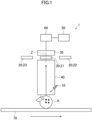
- FIG. 1 is a block diagram illustrating a configuration of the determination device (1) according to the first embodiment of the present invention.
- the determination device (1) includes an irradiator (10), extractors (20), an imager (30), a guide (40), a storage (50), and a determiner (60).
- the irradiator (10) irradiates an object (A) with light.
- the object (A) of the first embodiment is a substance that fluoresces when irradiated with light.
- the object (A) is, for example, a food or a plant.
- the irradiator (10) irradiates the object (A) with light.
- the irradiator (10) emits ultraviolet rays.
- the ultraviolet rays emitted by the irradiator (10) have a wavelength of 200 nm or more and 400 nm or less, for example.
- Examples of the irradiator (10) include a light source that emits ultraviolet rays.
- Examples of the light source include a light source element, such as a light-emitting diode (LED) and a laser diode, an excimer lamp, an ultraviolet lamp, and a mercury lamp.
- the irradiator (10) irradiates the object (A) with ultraviolet rays, such that fluorescence is emitted from the surface of the object (A).
- the extractors (20) extract a fluorescence emission having a predetermined wavelength out of the fluorescence emissions generated from the surface of the object (A).
- the predetermined wavelength is, for example, 550 nm or more and 750 nm or less.
- Examples of the extractors (20) include a band-pass filter.
- the number of the extractors (20) is two or more.
- the extractors (20) include a first extractor (21), a second extractor (22) and a third extractor (23).
- the first, second, and third extractors (21), (22), and (23) extract fluorescence emissions having wavelengths of 550 nm, 750 nm, and 400 nm, respectively, out of the fluorescence emissions generated from the surface of the object (A).
- the first extractor (21) extracts a fluorescence emission having a wavelength of 550 nm out of the fluorescence emissions generated from the surface of the object (A).
- the fluorescence emission extracted by the extractor (20) may be hereinafter referred to as the "predetermined fluorescence emission.”
- the imager (30) captures a fluorescence image showing the predetermined fluorescence emission.
- Examples of the imager (30) include a camera.
- the guide (40) is disposed between the object (A) and the extractor (20).
- the guide (40) is a tubular member where both ends open near the object (A) and near the extractor (20).
- the guide (40) guides the fluorescence emissions generated from the object (A) toward the extractor (20).
- the guide (40) effectively allows the fluorescence emissions to have a sufficiently high directivity toward the extractor (20).
- the storage (50) includes a main memory (e.g., a semiconductor memory), such as a flash memory, a read only memory (ROM), and a random access memory (RAM), and may further include an auxiliary memory (e.g., a hard disk drive, a solid state drive (SSD), a secure digital (SD) memory card, or a universal serial bus (USB) flash memory).
- a main memory e.g., a semiconductor memory
- ROM read only memory
- RAM random access memory
- auxiliary memory e.g., a hard disk drive, a solid state drive (SSD), a secure digital (SD) memory card, or a universal serial bus (USB) flash memory.
- the storage (50) stores various computer programs executable by the determiner (60).
- the determiner (60) includes a processor, such as a central processing unit (CPU) or a microprocessor unit (MPU).
- the determiner (60) executes a computer program stored in the storage (50) so as to control elements of the determination device (1).
- the determiner (60) determines the state of the object (A) based on an index indicating the fluorescence intensity of the fluorescence image captured by the imager (30).
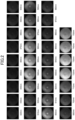
- FIG. 2 illustrates fluorescence images of fluorescence emissions having wavelengths of 420 nm to 750 nm.
- the fluorescence images of the same object (A) vary depending on the types of the extractors (20) (e.g., depending on which one is used among the extractor (20) that extracts a fluorescence emission having a wavelength of 420 nm and the extractor (20) that extracts a fluorescence emission having a wavelength of 750 nm is used).
- the fluorescence images vary depending on the state of the object (A).
- the state of the object (A) is determined using the correlation among the state of the object (A), the fluorescence images, and the type of the extractor (20).
- the first extractor (21) is used to extract a fluorescence emission having a wavelength of 550 nm out of the fluorescence emissions generated from the object (A).
- the imager (30) captures a fluorescence image indicating the fluorescence emission having a wavelength of 550 nm (a 550-nm fluorescence image).
- the determiner (60) outputs an index ⁇ 1 indicating the fluorescence intensity of the 550-nm fluorescence image.
- the index indicating the fluorescence intensity indicates, for example, an index value of pixel values of a plurality of pixels that constitute the fluorescence image.
- the index value indicates the mean value, the median value, the mode, the maximum value, or the minimum value.
- the index indicating the fluorescence intensity may be obtained by converting the index value of the pixel values into an optical value, such as lumen, candela, or lux, using a predetermined transformation, a table, or the like.
- the index indicating the fluorescence intensity may be an absolute value, or may be a relative value.
- the second extractor (22) is used to extract a fluorescence emission having a wavelength of 750 nm out of the fluorescence emissions generated from the object (A).
- the imager (30) captures a fluorescence image indicating the fluorescence emission having a wavelength of 750 nm (a 750-nm fluorescence image).
- the determiner (60) outputs an index ⁇ 2 indicating the fluorescence intensity of the 750-nm fluorescence image.
- the determiner (60) outputs a predicted value X of the chlorophyll content in the object (A) using the index ⁇ 1, the index ⁇ 2, and the following formula 1.
- the formula 1 is obtained, for example, by determining the correlation among the index ⁇ 1 indicating the fluorescence intensity of the 550-nm fluorescence image, the index ⁇ 2 indicating the fluorescence intensity of the 750-nm fluorescence image, and a measured value of the chlorophyll content through multivariate analysis or the like, and then expressing that correlation in the form of an approximate expression.
- the formula 1 is determined according to the type of the object (A). For example, if there is a strong correlation among an index ⁇ 3 indicating the fluorescence intensity of a 400-nm fluorescence image, the index ⁇ 1 indicating the fluorescence intensity of the 550-nm fluorescence image, and the measured value of the chlorophyll content, the formula 1 is expressed in the form of the approximate expression of the correlation among them. In this case, when the chlorophyll content in the object (A) is output using the formula 1, the third extractor (23) for a wavelength of 400 nm and the first extractor (21) for a wavelength of 550 nm are used.
- the determiner (60) compares the predicted value X of the chlorophyll content in the object (A) output using the formula 1 with a predetermined threshold value. If the predicted value X is the predetermined threshold value or more, the determiner (60) determines that the object (A) has a high degree of freshness (a non-defective product). If the predicted value X is less than the predetermined threshold value, the determiner (60) determines that the object (A) has a low degree of freshness (a defective product).
- Artificial intelligence may be used to determine whether the object (A) is a non-defective product or a defective product.
- a known machine learning device such as a neural network, is used to learn features of the fluorescence image observed when the object (A) is a non-defective product and features of the fluorescence image observed when the object (A) is a defective product, in order to determine whether the object (A) shown in a newly input fluorescence image is a non-defective product or a defective product.
- the determiner (60) determines the state of the object (A) based on the indexes each indicating the fluorescence intensity of a fluorescence image.
- the fluorescence image is used as described above, such that the entire surface of the object (A) that fluoresces in response to light emitted from the irradiator (10) can be captured as a target for determination.
- a larger part of the surface of the object (A) can be used for determination than in a typical spot determination process. Then, the determination accuracy can be improved.
- the formula 1 contains two variables: the indexes ⁇ 1 and ⁇ 2, but may contain one variable.
- the variable in the formula 1 may include the index ⁇ 1 only.
- extractors (20) only have to include a first extractor (21).
- the extractors (20) may include one extractor.
- the formula 1 is obtained by determining the correlation between the index ⁇ 1 indicating the fluorescence intensity of a 550-nm fluorescence image and a measured value of the chlorophyll content through multivariate analysis or the like, and then expressing that correlation in the form of an approximate expression.
- the formula 1 contains two variables: the indexes ⁇ 1 and ⁇ 2, but may contain three or more variables.
- the variables in the formula 1 may include the indexes ⁇ 1 and ⁇ 2 and an index ⁇ X.
- the index ⁇ X indicates the fluorescence intensity of an X-nm fluorescence image (a fluorescence image indicating a fluorescence emission having a wavelength of X nm).
- extractors (20) include a first extractor (21), a second extractor (22), and an X-th extractor. The X-th extractor extracts a fluorescence emission having a wavelength of X nm.
- the formula 1 is obtained by determining the correlation among the index ⁇ 1 indicating the fluorescence intensity of the 550-nm fluorescence image, the index ⁇ 2 indicating the fluorescence intensity of the 750-nm fluorescence image, the index ⁇ X indicating the fluorescence intensity of the X-nm fluorescence image, and a measured value of the chlorophyll content through multivariate analysis or the like, and then expressing that correlation in the form of an approximate expression.
- the determiner (60) determines the degree of freshness of the object (A) as a state of the object (A).
- the present invention is not limited to this.
- the determiner (60) may make determination for a ripened portion of the object (A) such as black spots on a banana, a rotten portion (a portion that has turned black) of the object (A), or the like, based on the pixel values (color shade) of the fluorescence images of the object (A).
- the determiner (60) when using the fluorescence images to determine the state of the object (A), uses all of the fluorescence images to determine the state of the entire imaged range of the object (A). However, the present invention is not limited to this. When using the fluorescence images to determine the state of the object (A), the determiner (60) may use part of the fluorescence images to determine the state of a partial region of the imaged range of the object (A) (such as an especially perishable region of the object (A)).
- the determination device (1) may include a scanning mechanism (70).
- the scanning mechanism (70) changes relative positions of the object (A) and each of the extractors (20) and the imager (30) relative to each other.
- Examples of the scanning mechanism (70) include a conveyor that conveys the object (A).
- the conveyor conveys the object (A) while the imager (30) successively captures images of the object (A), such that it is possible to easily capture an image of the entire object (A).
- the scanning mechanism (70) may move the extractors (20) and the imager (30).
- examples of the scanning mechanism (70) include a link mechanism, a slide mechanism, or a robot arm to which the extractors (20) and the imager (30) are attached.
- a determination device (1) may include a switching part (80).
- the switching part (80) switches an extractor (20) of a plurality of extractors (20) that is used when an imager (30) captures a fluorescence image.
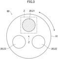
- the switching part (80) include a support (81), for example.
- the support (81) is disposed between the imager (30) and a guide (40) (see FIG. 1 ).
- the support (81) is supported rotatably about the Z axis.
- the support (81) is installed such that the plurality of extractors (20) are arranged around the Z axis.
- the plurality of extractors (20) rotate together with the support (81).
- the imager (30) captures a fluorescence image by using an extractor (20) of the plurality of extractors (20) that is disposed below the imager (30).
- the switching part (80) illustrated in FIG. 3 uses the first extractor (21) for the imager (30) to capture a fluorescence image. If the rotational angle of the support (81) is changed, an extractor (20) of the plurality of extractors (20) that is used when the imager (30) captures a fluorescence image is switched on. Accordingly, the extractors (20) can be easily switched.
- a determination device (1) may include a plurality of extractors (20) and a plurality of imagers (30). For example, if a plurality of extractors (20) include first to third extractors (21) to (23) (see FIG. 1 ), three imagers (30) (first to third imagers) are provided. The first to third extractors (21) to (23) are configured to be associated with the first to third imagers, respectively. An image of a fluorescence emission extracted by the first extractor (21) is captured by the first imager, an image of a fluorescence emission extracted by the second extractor is captured by the second imager, and an image of a fluorescence emission extracted by the third extractor is captured by the third imager. As a result, a plurality of fluorescence images with different wavelengths can be captured in a single shot. Thus, the determiner (60) can efficiently determine the state of the object (A).
- a determination device (2) that is a variation of the determination device (1) will be described with reference to FIG. 4 . Differences from the determination device (1) will be mainly described below.
- the determination device (2) includes a plurality of irradiators (10).
- the plurality of irradiators (10) emit ultraviolet rays each having a different excitation wavelength.
- the plurality of irradiators (10) include a first irradiator (11) that emits 325-nm ultraviolet rays, a second irradiator (12) that emits 365-nm ultraviolet rays, a third irradiator (13) that emits 375-nm ultraviolet rays, and a fourth irradiator (14) that emits 385-nm ultraviolet rays.
- the determination device (2) may include a plurality of extractors (20) or a single extractor (20).
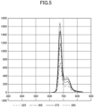
- the data can be obtained in the form of three-dimensional contours, including the excitation wavelength, the fluorescence wavelength, and the fluorescence intensity.
- the data in the form of three-dimensional contours may be hereinafter referred to as the "fluorescence fingerprint.”
- the fluorescence fingerprint is obtained for each of pixels of a fluorescence image.
- FIG. 5 shows a fluorescence fingerprint of one pixel in a fluorescence image of the object (A), where the imager (30) captures the fluorescence image by using each of the first irradiator (11) that emits 325-nm ultraviolet rays, the second irradiator (12) that emits 365-nm ultraviolet rays, the third irradiator (13) that emits 375-nm ultraviolet rays, and the fourth irradiator (14) that emits 385-nm ultraviolet rays. If a plurality of extractors (20) are used as illustrated in FIG. 4 so that a fluorescence image is captured for each of the extractors (20), a fluorescence fingerprint (see FIG.
- fluorescence fingerprint group each obtained for each pixel of the fluorescence image and further obtained for each extractor (20) may be collectively referred to as a "fluorescence fingerprint group.”
- the number of the extractors (20) to be used may be one. In this case, only one extractor (20) is used. and thus a fluorescence fingerprint is obtained for each pixel of a fluorescence image. If the only one extractor (20) is used as described above, fluorescence fingerprints each obtained for each pixel of the fluoroscopic image may be collectively referred to as a "fluorescence fingerprint group.”
- the storage (50) illustrated in FIG. 4 stores first association information indicating association between a plurality of different fluorescence fingerprint groups and a plurality of different states of the object (A).
- the determiner (60) acquires information indicating the fluorescence fingerprint group of the object (A) as a target for determination
- the determiner (60) selects, from the first association information, the state of the object (A) associated with the acquired fluorescence fingerprint group.
- the determiner (60) may use multivariate analysis, AI analysis, data mining, or the like to select the state of the object (A).
- the determiner (60) outputs the state of the object (A) selected from the first association information as the state of the object (A) as a target for determination. As a result, the determiner (60) can use the fluorescence fingerprints of the object (A) to determine the state of the object (A).
- a determination device (2) is used to identify the type of live bacteria or microorganisms that are parasitic on an object (A).
- the storage (50) illustrated in FIG. 4 stores second association information indicating association between a plurality of different fluorescence fingerprint groups and a plurality of different types of live bacteria or microorganisms.
- the determiner (60) selects, from the second association information, the live bacteria or microorganisms associated with the acquired fluorescence fingerprint group.
- the determiner (60) may use multivariate analysis, AI analysis, data mining, or the like to select the live bacteria or microorganisms.
- the determiner (60) outputs the live bacteria or microorganisms selected from the second association information as the live bacteria or microorganisms that are parasitic on the object (A) as a target for determination.
- the determiner (60) can use the fluorescence fingerprints of the object (A) to identify the type of live bacteria or microorganisms involved in degradation in the object (A).
- a determiner (60) of a determination device (1, 2) determines whether or not there is a sign of deterioration in quality of an object (A), which is an example of the state of the object (A).
- the inventors of this application observed the object (A) over a predetermined period to acquire fluorescence images of the object (A) on each of observation days, thereby acquiring data shown in FIGS. 6 to 14 .
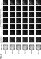
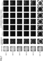
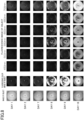
- FIGS. 6 to 8 illustrate data indicating association among an image of the object (A), a fluorescence color image of the object (A), and fluorescence images of the object (A) for each of a plurality of observation days.
- the inventors of this application observed the object (A), captured an image of the object (A) on each of the observation days, used the determination device (1, 2) shown in FIG. 1 or 4 to acquire fluorescence images, and accordingly acquired the data shown in FIGS. 6 to 9 .
- the object (A) shown in FIGS. 6 to 9 is a citrus fruit, such as Hebesu.
- the day number indicates the day of observation.
- the images of the object (A) are images of the object (A) directly captured.
- the images of the object (A) shown in FIGS. 6 to 9 are actually color images showing the colors of the outer surface of the object (A).
- the fluorescence color images of the object (A) are images captured without extracting a predetermined fluorescence emission out of fluorescence emissions generated from the surface of the object (A).
- the fluorescence color images of the object (A) shown in FIGS. 6 to 9 are actually color images showing the colors of the fluorescence emissions generated from the surface of the object (A).
- the fluorescence images of the object (A) are images obtained by capturing images of a plurality of predetermined fluorescence emissions each having a different wavelength (450 nm, 500 nm, 550 nm, 600 nm, 650 nm, and 750 nm) extracted out of the fluorescence emissions generated from the surface of the object (A).
- the fluorescence images of the object (A) are obtained by using, for example, the determination device (1, 2).
- the data shown in FIG. 6 were obtained by observing a normal object (A).
- the data shown in FIG. 7 were obtained by observing the object (A) that was being disordered due to rot, a lesion, or the like caused by mold or the like with the passage of time.
- the object (A) was placed in an environment of about 6°C, for example.
- the data shown in FIG. 8 were obtained by observing the object (A) that was refrigerated (e.g., at a temperature of about -1°C) and disordered by refrigeration with the passage of time.
- the disorder means that the object (A) is discolored in appearance.
- the normal object (A) used to acquire the data shown in FIG. 6 may be hereinafter referred to as the "normal fruit.”
- the object (A) that was being disordered due to rot, a lesion, or the like and that was used to acquire the data shown in FIG. 7 may be hereinafter referred to as a "first disordered fruit.”
- the object (A) that was being disordered by refrigeration that was used to acquire the data shown in FIG. 8 may be hereinafter referred to as a "second disordered fruit.”
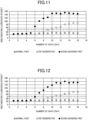
- the hatched circles indicate data on the normal fruit, the while hollow circles indicate data on the first disordered fruit, and the black-filled circles indicate data on the second disordered fruit.
- the vertical axis represents the index indicating the fluorescence intensity
- the horizontal axis represents the days of observation.
- the index indicating the fluorescence intensity is a value output based on pixel values of a plurality of pixels constituting the fluorescence image as described above. The greater the index indicating the fluorescence intensity is, the more the object (A) is disordered.
- FIG. 9 shows data indicating association between the observation days and the index indicating the fluorescence intensity of the associated 450-nm fluorescence image of each of the normal fruit, the first disordered fruit, and the second disordered fruit.
- the index indicating the fluorescence intensity associated with the first disordered fruit (while hollow circles) on day 8 in the data shown in FIG. 9 is output based on pixel values of a plurality of pixels constituting the fluorescence image on day 8 in the data shown in FIG. 7 .
- FIG. 10 is created based on the data on the 500-nm fluorescence images among the data shown in FIGS. 6 to 8 .
- FIG. 10 shows data indicating association between the observation days and the index indicating the fluorescence intensity of the associated 500-nm fluorescence image of each of the normal fruit, the first disordered fruit, and the second disordered fruit.
- FIG. 11 is created based on the data on the 550-nm fluorescence images among the data shown in FIGS. 6 to 8 .
- FIG. 11 shows data indicating association between the observation days and the index indicating the fluorescence intensity of the associated 550-nm fluorescence image of each of the normal fruit, the first disordered fruit, and the second disordered fruit.
- FIG. 12 is created based on the data on the 600-nm fluorescence images among the data shown in FIGS. 6 to 8 .
- FIG. 12 shows data indicating association between the observation days and the index indicating the fluorescence intensity of the associated 600-nm fluorescence image of each of the normal fruit, the first disordered fruit, and the second disordered fruit.
- FIG. 13 is created based on the data on the 650-nm fluorescence images among the data shown in FIGS. 6 to 8 .
- FIG. 13 shows data indicating association between the observation days and the index indicating the fluorescence intensity of the associated 650-nm fluorescence image of each of the normal fruit, the first disordered fruit, and the second disordered fruit.
- FIG. 14 is created based on the data on the 700-nm fluorescence images among the data shown in FIGS. 6 to 8 .
- FIG. 14 shows data indicating association between the observation days and the index indicating the fluorescence intensity of the associated 700-nm fluorescence image of each of the normal fruit, the first disordered fruit, and the second disordered fruit.
- the inventors of this application confirmed that the normal fruit was not disordered and hardly discolored in appearance even if the number of the observation days increased, and thus the fluorescence images hardly varied, as illustrated in FIG. 6 .
- the inventors of this application confirmed that the fluorescence images of the normal fruit hardly varied even if the number of the observation days increased, and thus the indexes indicating the fluorescence intensities of the fluorescence images also hardly varied, as illustrated in FIGS. 9 to 14 .
- each of the first and second disordered fruits was more disordered as the number of the observation days increased; thus each of the first and second disordered fruits was more discolored in appearance; and accordingly the change in the fluorescence image (the area of a whitish region) was larger, as illustrated in FIGS. 7 and 8 .
- the inventors of this application confirmed each of the first and second disordered fruits was more disordered as the number of the observation days increased; the change in the fluorescence image (the area of the whitish region) was larger; and accordingly the index indicating the fluorescence intensity of the fluorescence image increased, as illustrated in FIGS. 9 to 14 .
- the inventors of this application confirmed that the index indicating the fluorescence intensity of the fluorescence image of the second disordered fruit more increased than that of the first disordered fruit.
- the inventors of this application confirmed that if the object (A) was disordered (discolored) by sinensetin and nobiletin contained in the object (A), there appeared changes in the index indicating the fluorescence intensity of the 450-nm fluorescence image and the index indicating the fluorescence intensity of the 500-nm fluorescence image. Accordingly, the inventors of this application confirmed that the index indicating the fluorescence intensity of the 450-nm fluorescence image and the index indicating the fluorescence intensity of the 500-nm fluorescence image could be used as indexes for determining whether or not the object (A) was disordered (discolored) by sinensetin and nobiletin contained in the object (A).
- the inventors of this application confirmed that if the object (A) was disordered due to rot, there appeared a change in the index indicating the fluorescence intensity of the 550-nm fluorescence image. Accordingly, the inventors of this application confirmed that the index indicating the fluorescence intensity of the 550-nm fluorescence image could be used as an index for determining whether or not the object (A) was disordered by rot. The inventors of this application confirmed that the object (A) was disordered by Maillard reaction, there appeared changes in the index indicating the fluorescence intensity of the 600-nm fluorescence image and the index indicating the fluorescence intensity of the 650-nm fluorescence image.
- the inventors of this application confirmed that the index indicating the fluorescence intensity of the 600-nm fluorescence image and the index indicating the fluorescence intensity of the 650-nm fluorescence image could be used as indexes for determining whether or not the object (A) was disordered by Maillard reaction.
- the inventors of this application confirmed that the object (A) was disordered (discolored) by chlorophyll contained in the object (A), there appeared a change in the index indicating the fluorescence intensity of the 700-nm fluorescence image. Accordingly, the inventors of this application confirmed that the index indicating the fluorescence intensity of the 700-nm fluorescence image could be used as an index for determining whether or not the object (A) was disordered by chlorophyll contained in the object (A).
- the storage (50) (see FIGS. 1 and 4 ) of the determination device (1, 2) stores information indicating a predetermined threshold value ⁇ (see FIGS. 9 to 14 ).
- the determination device (1, 2) uses the threshold value ⁇ to determine whether or not the object (A) is disordered.
- the determiner (60) of the determination device (1, 2) performs a fluorescence image acquisition process.
- the fluorescence image acquisition process is a process in which the determiner (60) acquires data of a fluorescence image generated by the irradiator (10) irradiating the object (A) with light; the extractor (20) extracting a predetermined fluorescence emission generated from the surface of the object (A); and the imager (30) capturing the fluorescence image indicating the predetermined fluorescence emission.
- the determiner (60) acquires data of fluorescence images indicating a plurality of predetermined fluorescence emissions each having a different wavelength.
- the determiner (60) acquires a 450-nm fluorescence image (a fluorescence image indicating a predetermined fluorescence emission having a wavelength of 450 nm), a 500-nm fluorescence image, a 550-nm fluorescence image, a 600-nm fluorescence image, a 650-nm fluorescence image, and a 750-nm fluorescence image.
- a 450-nm fluorescence image a fluorescence image indicating a predetermined fluorescence emission having a wavelength of 450 nm
- step S20 the determiner (60) performs a fluorescence intensity output process.
- the fluorescence intensity output process is a process of outputting the index indicating the fluorescence intensity based on the pixel values of the plurality of pixels constituting each of the fluorescence images acquired in step S10.
- the determiner (60) outputs an index indicating the fluorescence intensity of each of the plurality of fluorescence images acquired in step S10.
- the determiner (60) outputs the index indicating the fluorescence intensity of the 450-nm fluorescence image, the index indicating the fluorescence intensity of the 500-nm fluorescence image, the index indicating the fluorescence intensity of the 550-nm fluorescence image, the index indicating the fluorescence intensity of the 600-nm fluorescence image, the index indicating the fluorescence intensity of the 650-nm fluorescence image, and the index indicating the fluorescence intensity of the 750-nm fluorescence image.
- step S30 the determiner (60) determines whether or not at least one of the plurality of indexes each indicating the fluorescence intensity and output in step S20 is greater than the threshold value ⁇ .
- the determiner (60) determines whether or not at least one of the indexes is greater than the threshold value ⁇ among the index indicating the fluorescence intensity of the 450-nm fluorescence image, the index indicating the fluorescence intensity of the 500-nm fluorescence image, the index indicating the fluorescence intensity of the 550-nm fluorescence image, the index indicating the fluorescence intensity of the 600-nm fluorescence image, the index indicating the fluorescence intensity of the 650-nm fluorescence image, or the index indicating the fluorescence intensity of the 750-nm fluorescence image.
- step S30 If the determiner (60) determines that at least one of the plurality of indexes each indicating the fluorescence intensity is greater than the threshold value ⁇ (Yes in step S30), the process proceeds to step S40.
- step S30 If the determiner (60) determines that all of the plurality of indexes each indicating the fluorescence intensity are less than or equal to the threshold value ⁇ (No in step S30), the process proceeds to step S50.
- step S40 the determiner (60) determines that there is a sign of deterioration in quality of the object (A). As a result, the process ends.
- step S50 the determiner (60) determines that there is no sign of deterioration in quality of the object (A). If the determiner (60) determines that there is no sign of deterioration in quality of the object (A), the process proceeds to step S10, such that the processes shown in steps S10 to S30 are performed again. Then, the processes shown in steps S10 to S30 are repeated until the determiner (60) determines that there is a sign of deterioration in quality of the object (A). As a result, the processes shown in steps S10 to S30 are performed over time, and thus a temporal change in the object (A) can be observed.
- the extractors (20) extract the plurality of predetermined fluorescence emissions each having a different wavelength; the imager (30) performs, over time, the imaging process of capturing a fluorescence image of each of the predetermined fluorescence emissions over time; and the determiner (60) determines whether or not there is a sign of deterioration in quality of the object (A) based on the indexes each indicating the fluorescence intensity of the associated fluorescence image acquired through the imaging process performed over time.
- the determiner (60) determines whether or not there is a sign of deterioration in quality of the object (A) based on the indexes each indicating the fluorescence intensity of the associated fluorescence image acquired through the imaging process performed over time.
- the determiner (60) performs a fluorescence image acquisition process.
- the determiner (60) acquires data of a fluorescence image indicating a predetermined fluorescence emission having one wavelength.
- the determiner (60) acquires data of a fluorescence image indicating a predetermined fluorescence emission having a wavelength of 500 nm.
- step S20 the determiner (60) performs a fluorescence intensity output process.
- the determiner (60) acquires an index indicating the fluorescence intensity of a fluorescence image indicating one predetermined fluorescence emission (e.g., a 500-nm fluorescence image).
- step S30 the determiner (60) determines whether or not the index indicating the fluorescence intensity and output in step S20 is greater than the threshold value ⁇ . If the determiner (60) determines that the index indicating the fluorescence intensity is greater than the threshold value ⁇ (Yes in step S30), the process proceeds to step S40. If the determiner (60) determines that the index indicating the fluorescence intensity is less than or equal to the threshold value ⁇ (No in step S30), the process proceeds to step S50.
- the imager (30) captures a fluorescence image over time, and the determiner (60) determines whether or not there is a sign of deterioration in quality of the object (A) based on the index of the fluorescence image captured over time.
- the determiner (60) acquires data of a fluorescence image indicating a predetermined fluorescence emission having one wavelength, and thus the extractor (20) can have a more simple device configuration than in the first example in which data of the fluorescence image indicating the predetermined fluorescence emissions having a plurality of wavelengths are acquired.
- the present disclosure is useful for a determination device.
Landscapes
- Health & Medical Sciences (AREA)
- Life Sciences & Earth Sciences (AREA)
- Chemical & Material Sciences (AREA)
- Immunology (AREA)
- Pathology (AREA)
- General Physics & Mathematics (AREA)
- Physics & Mathematics (AREA)
- General Health & Medical Sciences (AREA)
- Analytical Chemistry (AREA)
- Biochemistry (AREA)
- Nuclear Medicine, Radiotherapy & Molecular Imaging (AREA)
- Engineering & Computer Science (AREA)
- Food Science & Technology (AREA)
- Biomedical Technology (AREA)
- Molecular Biology (AREA)
- Medicinal Chemistry (AREA)
- Investigating, Analyzing Materials By Fluorescence Or Luminescence (AREA)
- Investigating Materials By The Use Of Optical Means Adapted For Particular Applications (AREA)
Abstract
Description
- The present disclosure relates to a determination device.
- A device for determining the degree of freshness/maturity described in
Patent Document 1 includes a container, a light source, an optical sensor, and a control unit. The container stores fresh food. The light source irradiates the fresh food placed in the container with visible light. The optical sensor detects the light intensity of a predetermined wavelength region of light reflected from the fresh food irradiated with the visible light. The control unit determines the degree of freshness or maturity of the fresh food based on the light intensity of the predetermined wavelength region detected by the optical sensor. - Patent Document 1:
Japanese Unexamined Patent Publication No. 2018-096712 - The device for determining the degree of freshness/maturity described in
Patent Document 1 determines only the states of points of the fresh food irradiated with visible light. Thus, if the state of whole fresh food as an object is determined, the accuracy of this determination may decrease. - It is an object of the present disclosure to reduce a decrease in accuracy of determination of the state of an object.
- A first aspect of the present disclosure is directed to a determination device. The determination device includes: an irradiator (10) configured to irradiate an object (A) including a food or a plant with a light; an extractor (20) configured to extract a predetermined fluorescence emission having a predetermined wavelength out of fluorescence emissions generated from a surface of the object (A) irradiated with the light; an imager (30) configured to capture a fluorescence image indicating the predetermined fluorescence emission; and a determiner (60) configured to determine a state of the object (A) based on an index indicating a fluorescence intensity of the fluorescence image.
- The first aspect can reduce a decrease in accuracy of determination of the state of the object (A).
- A second aspect of the present disclosure is an embodiment of the first aspect. In the second aspect, the determiner (60) determines the state of the object (A) based on the fluorescence image including a plurality of fluorescence images, and the predetermined fluorescence emission indicated by the fluorescence image has a different wavelength for each of the fluorescence images.
- According to the second aspect, the determiner (60) uses the plurality of fluorescence images to determine the state of the object (A), thereby further improving the determination accuracy.
- A third aspect of the present disclosure is an embodiment of the first or second aspect. In the third aspect, the determination device includes a scanning mechanism (70) configured to change relative positions of the object (A) and the imager (30) relative to each other.
- According to the third aspect, the fluorescence image of the entire object (A) can be acquired.
- A fourth aspect of the present disclosure is an embodiment of the first to third aspects. In the fourth aspect, the predetermined wavelength is 550 nm or more and 750 nm or less.
- According to the fourth aspect, the extractor (20) can extract the predetermined fluorescence emission having a wavelength of 550 nm or more and 750 nm or less.
- A fifth aspect of the present disclosure is an embodiment of any one of the first to fourth aspects. In the fifth aspect, the irradiator (10) emits ultraviolet rays.
- According to the fifth aspect, ultraviolet rays are emitted from the irradiator (10), and thus a fluorescence emission can be generated from the object (A).
- A sixth aspect of the present disclosure is an embodiment of the fifth aspect. In the sixth aspect, the ultraviolet rays have a wavelength of 200 nm or more and 400 nm or less.
- According to the sixth aspect, the irradiator (10) can emit ultraviolet rays having a wavelength of 200 nm or more and 400 nm or less.
- A seventh aspect of the present disclosure is an embodiment of any one of the first to sixth aspects. In the seventh aspect, the imager (30) captures the fluoroscopic image over time, and the determiner (60) determines whether or not there is a sign of deterioration in quality of the object (A) based on the index of the fluorescence image captured over time.
- According to the seventh aspect, by checking the index indicating the fluorescence intensity of the fluorescence image acquired over time, it is possible to check a temporal change in the state of the object (A).
- An eighth aspect of the present disclosure is an embodiment of any one of the first to sixth aspects. In the eighth aspect, the extractor (20) extracts the predetermined fluorescence emission including a plurality of predetermined fluorescence emissions each having a different wavelength, the imager (30) performs an imaging process of capturing a fluorescence image of each of the predetermined fluorescence emissions over time, and the determiner (60) determines whether or not there is a sign of deterioration in quality of the object (A) based on the index of each of the fluorescence images acquired through the imaging process performed over time.
- According to the eighth aspect, by checking the indexes each indicating the fluorescence intensity of the associated fluorescence image acquired through the imaging process performed over time, it is possible to check a temporal change in the state of the object (A).
- A ninth aspect of the present disclosure is an embodiment of any one of the first to eighth aspects. In the ninth aspect, the extractor (20) includes a band-pass filter.
- According to the ninth aspect, the band-pass filter can extract the predetermined fluorescence emission.
- A tenth aspect of the present disclosure is an embodiment of the ninth aspect. In the tenth aspect, the determination device further includes the band-pass filter including a plurality of band-pass filters, and a switching part (80) configured to switch one of the plurality of band-pass filters that is used to extract the predetermined fluorescence emission; and each of the band-pass filters extracts the predetermined fluorescence emission having a different wavelength.
- According to the tenth aspect, the switching part switching the plurality of band-pass filters enables easy acquisition of the plurality of fluorescence images of the predetermined fluorescence emissions having different wavelengths.
- An eleventh aspect of the present disclosure is an embodiment of any one of the first to tenth aspects. In the eleventh aspect, the determination device further includes the extractor (20) including a plurality of extractors (20), and the imager (30) including a plurality of the imagers (30); and each of the extractors (20) extracts the predetermined fluorescence emission having a different wavelength; and the plurality of extractors (20) are associated with the plurality of imagers (30).
- According to the eleventh aspect, the plurality of extractors (20) and the plurality of imagers (30) are used, such that the plurality of fluorescence images having different wavelengths can be acquired all at once. Thus, the process of determining the state of the object (A) can be performed efficiently.
- A twelfth aspect of the present disclosure is an embodiment of any one of the first to eleventh aspects. In the twelfth aspect, the irradiator (10) emits the light including a plurality of lights having different excitation wavelengths, and the determiner (60) determines the state of the object (A) based on the index including a plurality of indexes associated with the plurality of lights.
- According to the twelfth aspect, a fluorescence fingerprint including the plurality of indexes is used, such that the state of the object (A) can be determined.
- A thirteenth aspect of the present disclosure is an embodiment of the twelfth aspect. In the thirteenth aspect, the determiner (60) identifies a type of a live bacterium or a microorganism that is parasitic on the object (A) based on the plurality of indexes.
- In the thirteenth aspect, the fluorescence fingerprint including the plurality of indexes is used, such that the type of the live bacterium or the microorganism involved in degradation in the object (A) can be identified.
-
-
FIG. 1 is a block diagram illustrating a configuration of a determination device according to a first embodiment of the present invention. -
FIG. 2 illustrates fluorescence images of fluorescence emissions having wavelengths of 420 nm to 750 nm. -
FIG. 3 illustrates a switching part. -
FIG. 4 illustrates a variation of the determination device (1) according to the first embodiment. -
FIG. 5 shows a fluorescence fingerprint. -
FIG. 6 illustrates an example of data indicating association among an image of an object, a fluorescence color image of the object, and fluorescence images of the object for each of a plurality of observation days. -
FIG. 7 illustrates an example of data indicating association among an image of an object, a fluorescence color image of the object, and fluorescence images of the object for each of a plurality of observation days. -
FIG. 8 illustrates an example of data indicating association among an image of an object, a fluorescence color image of the object, and fluorescence images of the object for each of a plurality of observation days. -
FIG. 9 is an example of a graph showing an index indicating the fluorescence intensity on each of a plurality of observation days. -
FIG. 10 is an example of a graph showing an index indicating the fluorescence intensity on each of a plurality of observation days. -
FIG. 11 is an example of a graph showing an index indicating the fluorescence intensity on each of a plurality of observation days. -
FIG. 12 is an example of a graph showing an index indicating the fluorescence intensity on each of a plurality of observation days. -
FIG. 13 is an example of a graph showing an index indicating the fluorescence intensity on each of a plurality of observation days. -
FIG. 14 is an example of a graph showing an index indicating the fluorescence intensity on each of a plurality of observation days. -
FIG. 15 is a flowchart relating to a determination made by the determination device. - Embodiments of the present invention will be described in detail with reference to the drawings. Note that like reference characters denote the same or equivalent components in the drawings, and the detailed description thereof, the description of advantages associated therewith, and other descriptions will not be repeated.
- A determination device (1) according to a first embodiment of the present invention will be described with reference to
FIG. 1. FIG. 1 is a block diagram illustrating a configuration of the determination device (1) according to the first embodiment of the present invention. - As illustrated in
FIG. 1 , the determination device (1) includes an irradiator (10), extractors (20), an imager (30), a guide (40), a storage (50), and a determiner (60). - The irradiator (10) irradiates an object (A) with light. The object (A) of the first embodiment is a substance that fluoresces when irradiated with light. The object (A) is, for example, a food or a plant.
- In the first embodiment, the irradiator (10) irradiates the object (A) with light. In the first embodiment, the irradiator (10) emits ultraviolet rays. The ultraviolet rays emitted by the irradiator (10) have a wavelength of 200 nm or more and 400 nm or less, for example. Examples of the irradiator (10) include a light source that emits ultraviolet rays. Examples of the light source include a light source element, such as a light-emitting diode (LED) and a laser diode, an excimer lamp, an ultraviolet lamp, and a mercury lamp. The irradiator (10) irradiates the object (A) with ultraviolet rays, such that fluorescence is emitted from the surface of the object (A).
- The extractors (20) extract a fluorescence emission having a predetermined wavelength out of the fluorescence emissions generated from the surface of the object (A). The predetermined wavelength is, for example, 550 nm or more and 750 nm or less. Examples of the extractors (20) include a band-pass filter. The number of the extractors (20) is two or more. In the first embodiment, the extractors (20) include a first extractor (21), a second extractor (22) and a third extractor (23). The first, second, and third extractors (21), (22), and (23) extract fluorescence emissions having wavelengths of 550 nm, 750 nm, and 400 nm, respectively, out of the fluorescence emissions generated from the surface of the object (A).
- One of the extractors (20) to be used faces the object (A). In
FIG. 1 , the first extractor (21) is used. The first extractor (21) extracts a fluorescence emission having a wavelength of 550 nm out of the fluorescence emissions generated from the surface of the object (A). - The fluorescence emission extracted by the extractor (20) may be hereinafter referred to as the "predetermined fluorescence emission."
- The imager (30) captures a fluorescence image showing the predetermined fluorescence emission. Examples of the imager (30) include a camera.
- The guide (40) is disposed between the object (A) and the extractor (20). The guide (40) is a tubular member where both ends open near the object (A) and near the extractor (20). The guide (40) guides the fluorescence emissions generated from the object (A) toward the extractor (20). The guide (40) effectively allows the fluorescence emissions to have a sufficiently high directivity toward the extractor (20).
- The storage (50) includes a main memory (e.g., a semiconductor memory), such as a flash memory, a read only memory (ROM), and a random access memory (RAM), and may further include an auxiliary memory (e.g., a hard disk drive, a solid state drive (SSD), a secure digital (SD) memory card, or a universal serial bus (USB) flash memory). The storage (50) stores various computer programs executable by the determiner (60).
- The determiner (60) includes a processor, such as a central processing unit (CPU) or a microprocessor unit (MPU). The determiner (60) executes a computer program stored in the storage (50) so as to control elements of the determination device (1).
- The determiner (60) determines the state of the object (A) based on an index indicating the fluorescence intensity of the fluorescence image captured by the imager (30).
-
FIG. 2 illustrates fluorescence images of fluorescence emissions having wavelengths of 420 nm to 750 nm. As illustrated inFIG. 2 , the fluorescence images of the same object (A) vary depending on the types of the extractors (20) (e.g., depending on which one is used among the extractor (20) that extracts a fluorescence emission having a wavelength of 420 nm and the extractor (20) that extracts a fluorescence emission having a wavelength of 750 nm is used). Even if the extractor (20) of the same type is used (e.g., even if only the extractor (20) that extracts a fluorescence emission having a wavelength of 420 nm is used), the fluorescence images vary depending on the state of the object (A). - In the first embodiment, the state of the object (A) is determined using the correlation among the state of the object (A), the fluorescence images, and the type of the extractor (20).
- As illustrated in
FIG. 1 , the first extractor (21) is used to extract a fluorescence emission having a wavelength of 550 nm out of the fluorescence emissions generated from the object (A). The imager (30) captures a fluorescence image indicating the fluorescence emission having a wavelength of 550 nm (a 550-nm fluorescence image). The determiner (60) outputs an index λ1 indicating the fluorescence intensity of the 550-nm fluorescence image. The index indicating the fluorescence intensity indicates, for example, an index value of pixel values of a plurality of pixels that constitute the fluorescence image. The index value indicates the mean value, the median value, the mode, the maximum value, or the minimum value. The index indicating the fluorescence intensity may be obtained by converting the index value of the pixel values into an optical value, such as lumen, candela, or lux, using a predetermined transformation, a table, or the like. The index indicating the fluorescence intensity may be an absolute value, or may be a relative value. - The second extractor (22) is used to extract a fluorescence emission having a wavelength of 750 nm out of the fluorescence emissions generated from the object (A). The imager (30) captures a fluorescence image indicating the fluorescence emission having a wavelength of 750 nm (a 750-nm fluorescence image). The determiner (60) outputs an index λ2 indicating the fluorescence intensity of the 750-nm fluorescence image.
- The determiner (60) outputs a predicted value X of the chlorophyll content in the object (A) using the index λ1, the index λ2, and the following
formula 1. Theformula 1 is stored in the storage (50).
[Formula 1] X = 13.35 + 10.74λ2 - 82.62λ1
- The
formula 1 is obtained, for example, by determining the correlation among the index λ1 indicating the fluorescence intensity of the 550-nm fluorescence image, the index λ2 indicating the fluorescence intensity of the 750-nm fluorescence image, and a measured value of the chlorophyll content through multivariate analysis or the like, and then expressing that correlation in the form of an approximate expression. - The
formula 1 is determined according to the type of the object (A). For example, if there is a strong correlation among an index λ3 indicating the fluorescence intensity of a 400-nm fluorescence image, the index λ1 indicating the fluorescence intensity of the 550-nm fluorescence image, and the measured value of the chlorophyll content, theformula 1 is expressed in the form of the approximate expression of the correlation among them. In this case, when the chlorophyll content in the object (A) is output using theformula 1, the third extractor (23) for a wavelength of 400 nm and the first extractor (21) for a wavelength of 550 nm are used. - The determiner (60) compares the predicted value X of the chlorophyll content in the object (A) output using the
formula 1 with a predetermined threshold value. If the predicted value X is the predetermined threshold value or more, the determiner (60) determines that the object (A) has a high degree of freshness (a non-defective product). If the predicted value X is less than the predetermined threshold value, the determiner (60) determines that the object (A) has a low degree of freshness (a defective product). - Artificial intelligence (AI) may be used to determine whether the object (A) is a non-defective product or a defective product. In this case, a known machine learning device, such as a neural network, is used to learn features of the fluorescence image observed when the object (A) is a non-defective product and features of the fluorescence image observed when the object (A) is a defective product, in order to determine whether the object (A) shown in a newly input fluorescence image is a non-defective product or a defective product.
- As described above, the determiner (60) determines the state of the object (A) based on the indexes each indicating the fluorescence intensity of a fluorescence image. The fluorescence image is used as described above, such that the entire surface of the object (A) that fluoresces in response to light emitted from the irradiator (10) can be captured as a target for determination. Thus, a larger part of the surface of the object (A) can be used for determination than in a typical spot determination process. Then, the determination accuracy can be improved.
- In the first embodiment, the
formula 1 contains two variables: the indexes λ1 and λ2, but may contain one variable. For example, the variable in theformula 1 may include the index λ1 only. In this case, extractors (20) only have to include a first extractor (21). In other words, the extractors (20) may include one extractor. In this case, theformula 1 is obtained by determining the correlation between the index λ1 indicating the fluorescence intensity of a 550-nm fluorescence image and a measured value of the chlorophyll content through multivariate analysis or the like, and then expressing that correlation in the form of an approximate expression. - In the first embodiment, the
formula 1 contains two variables: the indexes λ1 and λ2, but may contain three or more variables. For example, the variables in theformula 1 may include the indexes λ1 and λ2 and an index λX. The index λX indicates the fluorescence intensity of an X-nm fluorescence image (a fluorescence image indicating a fluorescence emission having a wavelength of X nm). In this case, extractors (20) include a first extractor (21), a second extractor (22), and an X-th extractor. The X-th extractor extracts a fluorescence emission having a wavelength of X nm. In this case, theformula 1 is obtained by determining the correlation among the index λ1 indicating the fluorescence intensity of the 550-nm fluorescence image, the index λ2 indicating the fluorescence intensity of the 750-nm fluorescence image, the index λX indicating the fluorescence intensity of the X-nm fluorescence image, and a measured value of the chlorophyll content through multivariate analysis or the like, and then expressing that correlation in the form of an approximate expression. - In each of the first to third embodiments, the determiner (60) determines the degree of freshness of the object (A) as a state of the object (A). However, the present invention is not limited to this. For example, the determiner (60) may make determination for a ripened portion of the object (A) such as black spots on a banana, a rotten portion (a portion that has turned black) of the object (A), or the like, based on the pixel values (color shade) of the fluorescence images of the object (A).
- In each of the first to fourth embodiments, when using the fluorescence images to determine the state of the object (A), the determiner (60) uses all of the fluorescence images to determine the state of the entire imaged range of the object (A). However, the present invention is not limited to this. When using the fluorescence images to determine the state of the object (A), the determiner (60) may use part of the fluorescence images to determine the state of a partial region of the imaged range of the object (A) (such as an especially perishable region of the object (A)).
- As illustrated in
FIG. 1 , the determination device (1) may include a scanning mechanism (70). The scanning mechanism (70) changes relative positions of the object (A) and each of the extractors (20) and the imager (30) relative to each other. Examples of the scanning mechanism (70) include a conveyor that conveys the object (A). - If the object (A) is partially outside the imaged range of the imager (30), and an image of the entire object (A) cannot be captured in a single shot, the conveyor conveys the object (A) while the imager (30) successively captures images of the object (A), such that it is possible to easily capture an image of the entire object (A). The scanning mechanism (70) may move the extractors (20) and the imager (30). In this case, examples of the scanning mechanism (70) include a link mechanism, a slide mechanism, or a robot arm to which the extractors (20) and the imager (30) are attached.
- As illustrated in
FIG. 3 , a determination device (1) may include a switching part (80). The switching part (80) switches an extractor (20) of a plurality of extractors (20) that is used when an imager (30) captures a fluorescence image. The switching part (80) include a support (81), for example. The support (81) is disposed between the imager (30) and a guide (40) (seeFIG. 1 ). The support (81) is supported rotatably about the Z axis. The support (81) is installed such that the plurality of extractors (20) are arranged around the Z axis. The plurality of extractors (20) rotate together with the support (81). The imager (30) captures a fluorescence image by using an extractor (20) of the plurality of extractors (20) that is disposed below the imager (30). The switching part (80) illustrated inFIG. 3 uses the first extractor (21) for the imager (30) to capture a fluorescence image. If the rotational angle of the support (81) is changed, an extractor (20) of the plurality of extractors (20) that is used when the imager (30) captures a fluorescence image is switched on. Accordingly, the extractors (20) can be easily switched. - A determination device (1) may include a plurality of extractors (20) and a plurality of imagers (30). For example, if a plurality of extractors (20) include first to third extractors (21) to (23) (see
FIG. 1 ), three imagers (30) (first to third imagers) are provided. The first to third extractors (21) to (23) are configured to be associated with the first to third imagers, respectively. An image of a fluorescence emission extracted by the first extractor (21) is captured by the first imager, an image of a fluorescence emission extracted by the second extractor is captured by the second imager, and an image of a fluorescence emission extracted by the third extractor is captured by the third imager. As a result, a plurality of fluorescence images with different wavelengths can be captured in a single shot. Thus, the determiner (60) can efficiently determine the state of the object (A). - A determination device (2) that is a variation of the determination device (1) will be described with reference to
FIG. 4 . Differences from the determination device (1) will be mainly described below. - As illustrated in
FIG. 4 , the determination device (2) includes a plurality of irradiators (10). The plurality of irradiators (10) emit ultraviolet rays each having a different excitation wavelength. In the eighth embodiment, the plurality of irradiators (10) include a first irradiator (11) that emits 325-nm ultraviolet rays, a second irradiator (12) that emits 365-nm ultraviolet rays, a third irradiator (13) that emits 375-nm ultraviolet rays, and a fourth irradiator (14) that emits 385-nm ultraviolet rays. - The determination device (2) may include a plurality of extractors (20) or a single extractor (20).
- As illustrated in
FIG. 5 , if the excitation wavelengths of ultraviolet rays emitted to the object (A) from the plurality of irradiators (10) (the first to fourth irradiators (11) to (14)) are changed, the data can be obtained in the form of three-dimensional contours, including the excitation wavelength, the fluorescence wavelength, and the fluorescence intensity. The data in the form of three-dimensional contours may be hereinafter referred to as the "fluorescence fingerprint." The fluorescence fingerprint is obtained for each of pixels of a fluorescence image.FIG. 5 shows a fluorescence fingerprint of one pixel in a fluorescence image of the object (A), where the imager (30) captures the fluorescence image by using each of the first irradiator (11) that emits 325-nm ultraviolet rays, the second irradiator (12) that emits 365-nm ultraviolet rays, the third irradiator (13) that emits 375-nm ultraviolet rays, and the fourth irradiator (14) that emits 385-nm ultraviolet rays. If a plurality of extractors (20) are used as illustrated inFIG. 4 so that a fluorescence image is captured for each of the extractors (20), a fluorescence fingerprint (seeFIG. 5 ) is obtained for each pixel of the fluorescence image and further obtained for each extractor (20). If the plurality of extractors (20) are used as described above, fluorescence fingerprints each obtained for each pixel of the fluorescence image and further obtained for each extractor (20) may be collectively referred to as a "fluorescence fingerprint group." - Note that the number of the extractors (20) to be used may be one. In this case, only one extractor (20) is used. and thus a fluorescence fingerprint is obtained for each pixel of a fluorescence image. If the only one extractor (20) is used as described above, fluorescence fingerprints each obtained for each pixel of the fluoroscopic image may be collectively referred to as a "fluorescence fingerprint group."
- A configuration in which a determiner (60) determines the state of the object (A) using the fluorescence fingerprint group will be described.
- The storage (50) illustrated in
FIG. 4 stores first association information indicating association between a plurality of different fluorescence fingerprint groups and a plurality of different states of the object (A). When the object (A) as a target for determination is irradiated with a plurality of ultraviolet rays having different wavelengths, and the determiner (60) acquires information indicating the fluorescence fingerprint group of the object (A) as a target for determination, the determiner (60) selects, from the first association information, the state of the object (A) associated with the acquired fluorescence fingerprint group. In this case, the determiner (60) may use multivariate analysis, AI analysis, data mining, or the like to select the state of the object (A). The determiner (60) outputs the state of the object (A) selected from the first association information as the state of the object (A) as a target for determination. As a result, the determiner (60) can use the fluorescence fingerprints of the object (A) to determine the state of the object (A). - In a ninth embodiment, a determination device (2) is used to identify the type of live bacteria or microorganisms that are parasitic on an object (A). In this case, the storage (50) illustrated in
FIG. 4 stores second association information indicating association between a plurality of different fluorescence fingerprint groups and a plurality of different types of live bacteria or microorganisms. When the object (A) as a target for determination is irradiated with a plurality of ultraviolet rays having different wavelengths, and a determiner (60) acquires information indicating the fluorescence fingerprint group of the object (A) as a target for determination, the determiner (60) selects, from the second association information, the live bacteria or microorganisms associated with the acquired fluorescence fingerprint group. In this case, the determiner (60) may use multivariate analysis, AI analysis, data mining, or the like to select the live bacteria or microorganisms. The determiner (60) outputs the live bacteria or microorganisms selected from the second association information as the live bacteria or microorganisms that are parasitic on the object (A) as a target for determination. As a result, the determiner (60) can use the fluorescence fingerprints of the object (A) to identify the type of live bacteria or microorganisms involved in degradation in the object (A). - In a tenth embodiment, a determiner (60) of a determination device (1, 2) determines whether or not there is a sign of deterioration in quality of an object (A), which is an example of the state of the object (A). The inventors of this application observed the object (A) over a predetermined period to acquire fluorescence images of the object (A) on each of observation days, thereby acquiring data shown in
FIGS. 6 to 14 . -
FIGS. 6 to 8 illustrate data indicating association among an image of the object (A), a fluorescence color image of the object (A), and fluorescence images of the object (A) for each of a plurality of observation days. To examine the correlation between a temporal change in the object (A) and the fluorescence images, the inventors of this application observed the object (A), captured an image of the object (A) on each of the observation days, used the determination device (1, 2) shown inFIG. 1 or4 to acquire fluorescence images, and accordingly acquired the data shown inFIGS. 6 to 9 . In the tenth embodiment, the object (A) shown inFIGS. 6 to 9 is a citrus fruit, such as Hebesu. - In
FIGS. 6 to 8 , the day number, such asday 1 orday 2, indicates the day of observation. InFIGS. 6 to 8 , the images of the object (A) are images of the object (A) directly captured. The images of the object (A) shown inFIGS. 6 to 9 are actually color images showing the colors of the outer surface of the object (A). InFIGS. 6 to 8 , the fluorescence color images of the object (A) are images captured without extracting a predetermined fluorescence emission out of fluorescence emissions generated from the surface of the object (A). The fluorescence color images of the object (A) shown inFIGS. 6 to 9 are actually color images showing the colors of the fluorescence emissions generated from the surface of the object (A). The fluorescence images of the object (A) are images obtained by capturing images of a plurality of predetermined fluorescence emissions each having a different wavelength (450 nm, 500 nm, 550 nm, 600 nm, 650 nm, and 750 nm) extracted out of the fluorescence emissions generated from the surface of the object (A). The fluorescence images of the object (A) are obtained by using, for example, the determination device (1, 2). - The data shown in
FIG. 6 were obtained by observing a normal object (A). The data shown inFIG. 7 were obtained by observing the object (A) that was being disordered due to rot, a lesion, or the like caused by mold or the like with the passage of time. When the data shown inFIGS. 6 and7 were acquired, the object (A) was placed in an environment of about 6°C, for example. The data shown inFIG. 8 were obtained by observing the object (A) that was refrigerated (e.g., at a temperature of about -1°C) and disordered by refrigeration with the passage of time. The disorder means that the object (A) is discolored in appearance. - The normal object (A) used to acquire the data shown in
FIG. 6 may be hereinafter referred to as the "normal fruit." The object (A) that was being disordered due to rot, a lesion, or the like and that was used to acquire the data shown inFIG. 7 may be hereinafter referred to as a "first disordered fruit." The object (A) that was being disordered by refrigeration that was used to acquire the data shown inFIG. 8 may be hereinafter referred to as a "second disordered fruit." - In
FIGS. 9 to 14 , the hatched circles indicate data on the normal fruit, the while hollow circles indicate data on the first disordered fruit, and the black-filled circles indicate data on the second disordered fruit. In the data shown inFIGS. 9 to 14 , the vertical axis represents the index indicating the fluorescence intensity, and the horizontal axis represents the days of observation. The index indicating the fluorescence intensity is a value output based on pixel values of a plurality of pixels constituting the fluorescence image as described above. The greater the index indicating the fluorescence intensity is, the more the object (A) is disordered. - The data shown in
FIG. 9 are created based on the data on the 450-nm fluorescence images among the data shown inFIGS. 6 to 8 .FIG. 9 shows data indicating association between the observation days and the index indicating the fluorescence intensity of the associated 450-nm fluorescence image of each of the normal fruit, the first disordered fruit, and the second disordered fruit. For example, the index indicating the fluorescence intensity associated with the first disordered fruit (while hollow circles) onday 8 in the data shown inFIG. 9 is output based on pixel values of a plurality of pixels constituting the fluorescence image onday 8 in the data shown inFIG. 7 . -
FIG. 10 is created based on the data on the 500-nm fluorescence images among the data shown inFIGS. 6 to 8 .FIG. 10 shows data indicating association between the observation days and the index indicating the fluorescence intensity of the associated 500-nm fluorescence image of each of the normal fruit, the first disordered fruit, and the second disordered fruit. -
FIG. 11 is created based on the data on the 550-nm fluorescence images among the data shown inFIGS. 6 to 8 .FIG. 11 shows data indicating association between the observation days and the index indicating the fluorescence intensity of the associated 550-nm fluorescence image of each of the normal fruit, the first disordered fruit, and the second disordered fruit. -
FIG. 12 is created based on the data on the 600-nm fluorescence images among the data shown inFIGS. 6 to 8 .FIG. 12 shows data indicating association between the observation days and the index indicating the fluorescence intensity of the associated 600-nm fluorescence image of each of the normal fruit, the first disordered fruit, and the second disordered fruit. -
FIG. 13 is created based on the data on the 650-nm fluorescence images among the data shown inFIGS. 6 to 8 .FIG. 13 shows data indicating association between the observation days and the index indicating the fluorescence intensity of the associated 650-nm fluorescence image of each of the normal fruit, the first disordered fruit, and the second disordered fruit. -
FIG. 14 is created based on the data on the 700-nm fluorescence images among the data shown inFIGS. 6 to 8 .FIG. 14 shows data indicating association between the observation days and the index indicating the fluorescence intensity of the associated 700-nm fluorescence image of each of the normal fruit, the first disordered fruit, and the second disordered fruit. - The inventors of this application confirmed that the normal fruit was not disordered and hardly discolored in appearance even if the number of the observation days increased, and thus the fluorescence images hardly varied, as illustrated in
FIG. 6 . The inventors of this application confirmed that the fluorescence images of the normal fruit hardly varied even if the number of the observation days increased, and thus the indexes indicating the fluorescence intensities of the fluorescence images also hardly varied, as illustrated inFIGS. 9 to 14 . - The inventors of this application confirmed that each of the first and second disordered fruits was more disordered as the number of the observation days increased; thus each of the first and second disordered fruits was more discolored in appearance; and accordingly the change in the fluorescence image (the area of a whitish region) was larger, as illustrated in
FIGS. 7 and8 . The inventors of this application confirmed each of the first and second disordered fruits was more disordered as the number of the observation days increased; the change in the fluorescence image (the area of the whitish region) was larger; and accordingly the index indicating the fluorescence intensity of the fluorescence image increased, as illustrated inFIGS. 9 to 14 . In addition, the inventors of this application confirmed that the index indicating the fluorescence intensity of the fluorescence image of the second disordered fruit more increased than that of the first disordered fruit. - In an early phase of disorder of each of the first disordered fruit (see
FIG. 7 ) and the second disordered fruit (seeFIG. 8 ), i.e., in a phase (e.g., on day 9) where there was a sign of deterioration in quality thereof, a slight change in the color of the appearance of the object (A) was found when the image of the object (A) was visually checked. Thus, the inventors of the present application confirmed that it was difficult to visually check the image of the object (A) to determine whether or not there was a sign of deterioration in quality of the object (A). - In contrast, if there was a sign of deterioration in quality of each of the first disordered fruit (see
FIG. 7 ) and the second disordered fruit (seeFIG. 8 ), a whitish region appeared in the fluorescence image onday 9 in each ofFIGS. 7 and8 , and thus there were increases in the index indicating the fluorescence intensity of the first disordered fruit (the while hollow circles) and the index indicating the fluorescence intensity of the second disordered fruit (the black-filled circles) onday 9 inFIGS. 9 to 14 . Thus, the inventors of the present application confirmed that by checking the index indicating the fluorescence intensity of the fluorescence image, it could be determined whether or not there was a sign of deterioration in quality of the object (A). - The inventors of this application confirmed that if the object (A) was disordered (discolored) by sinensetin and nobiletin contained in the object (A), there appeared changes in the index indicating the fluorescence intensity of the 450-nm fluorescence image and the index indicating the fluorescence intensity of the 500-nm fluorescence image. Accordingly, the inventors of this application confirmed that the index indicating the fluorescence intensity of the 450-nm fluorescence image and the index indicating the fluorescence intensity of the 500-nm fluorescence image could be used as indexes for determining whether or not the object (A) was disordered (discolored) by sinensetin and nobiletin contained in the object (A). The inventors of this application confirmed that if the object (A) was disordered due to rot, there appeared a change in the index indicating the fluorescence intensity of the 550-nm fluorescence image. Accordingly, the inventors of this application confirmed that the index indicating the fluorescence intensity of the 550-nm fluorescence image could be used as an index for determining whether or not the object (A) was disordered by rot. The inventors of this application confirmed that the object (A) was disordered by Maillard reaction, there appeared changes in the index indicating the fluorescence intensity of the 600-nm fluorescence image and the index indicating the fluorescence intensity of the 650-nm fluorescence image. Accordingly, the inventors of this application confirmed that the index indicating the fluorescence intensity of the 600-nm fluorescence image and the index indicating the fluorescence intensity of the 650-nm fluorescence image could be used as indexes for determining whether or not the object (A) was disordered by Maillard reaction. The inventors of this application confirmed that the object (A) was disordered (discolored) by chlorophyll contained in the object (A), there appeared a change in the index indicating the fluorescence intensity of the 700-nm fluorescence image. Accordingly, the inventors of this application confirmed that the index indicating the fluorescence intensity of the 700-nm fluorescence image could be used as an index for determining whether or not the object (A) was disordered by chlorophyll contained in the object (A).
- A first example of a procedure in which the determiner (60) of the determination device (1, 2) determines the sign of deterioration in quality of the object (A) will be described below.
- The storage (50) (see
FIGS. 1 and4 ) of the determination device (1, 2) stores information indicating a predetermined threshold value α (seeFIGS. 9 to 14 ). The determination device (1, 2) uses the threshold value α to determine whether or not the object (A) is disordered. - As illustrated in
FIGS. 1 ,4 , and15 , instep S 10, the determiner (60) of the determination device (1, 2) performs a fluorescence image acquisition process. The fluorescence image acquisition process is a process in which the determiner (60) acquires data of a fluorescence image generated by the irradiator (10) irradiating the object (A) with light; the extractor (20) extracting a predetermined fluorescence emission generated from the surface of the object (A); and the imager (30) capturing the fluorescence image indicating the predetermined fluorescence emission. The determiner (60) acquires data of fluorescence images indicating a plurality of predetermined fluorescence emissions each having a different wavelength. In the tenth embodiment, the determiner (60) acquires a 450-nm fluorescence image (a fluorescence image indicating a predetermined fluorescence emission having a wavelength of 450 nm), a 500-nm fluorescence image, a 550-nm fluorescence image, a 600-nm fluorescence image, a 650-nm fluorescence image, and a 750-nm fluorescence image. - In step S20, the determiner (60) performs a fluorescence intensity output process. The fluorescence intensity output process is a process of outputting the index indicating the fluorescence intensity based on the pixel values of the plurality of pixels constituting each of the fluorescence images acquired in step S10. In the tenth embodiment, the determiner (60) outputs an index indicating the fluorescence intensity of each of the plurality of fluorescence images acquired in step S10. Specifically, the determiner (60) outputs the index indicating the fluorescence intensity of the 450-nm fluorescence image, the index indicating the fluorescence intensity of the 500-nm fluorescence image, the index indicating the fluorescence intensity of the 550-nm fluorescence image, the index indicating the fluorescence intensity of the 600-nm fluorescence image, the index indicating the fluorescence intensity of the 650-nm fluorescence image, and the index indicating the fluorescence intensity of the 750-nm fluorescence image.
- In step S30, the determiner (60) determines whether or not at least one of the plurality of indexes each indicating the fluorescence intensity and output in step S20 is greater than the threshold value α. In the tenth embodiment, the determiner (60) determines whether or not at least one of the indexes is greater than the threshold value α among the index indicating the fluorescence intensity of the 450-nm fluorescence image, the index indicating the fluorescence intensity of the 500-nm fluorescence image, the index indicating the fluorescence intensity of the 550-nm fluorescence image, the index indicating the fluorescence intensity of the 600-nm fluorescence image, the index indicating the fluorescence intensity of the 650-nm fluorescence image, or the index indicating the fluorescence intensity of the 750-nm fluorescence image.
- If the determiner (60) determines that at least one of the plurality of indexes each indicating the fluorescence intensity is greater than the threshold value α (Yes in step S30), the process proceeds to step S40.
- If the determiner (60) determines that all of the plurality of indexes each indicating the fluorescence intensity are less than or equal to the threshold value α (No in step S30), the process proceeds to step S50.
- In step S40, the determiner (60) determines that there is a sign of deterioration in quality of the object (A). As a result, the process ends.
- In step S50, the determiner (60) determines that there is no sign of deterioration in quality of the object (A). If the determiner (60) determines that there is no sign of deterioration in quality of the object (A), the process proceeds to step S10, such that the processes shown in steps S10 to S30 are performed again. Then, the processes shown in steps S10 to S30 are repeated until the determiner (60) determines that there is a sign of deterioration in quality of the object (A). As a result, the processes shown in steps S10 to S30 are performed over time, and thus a temporal change in the object (A) can be observed.
- As described above, the extractors (20) extract the plurality of predetermined fluorescence emissions each having a different wavelength; the imager (30) performs, over time, the imaging process of capturing a fluorescence image of each of the predetermined fluorescence emissions over time; and the determiner (60) determines whether or not there is a sign of deterioration in quality of the object (A) based on the indexes each indicating the fluorescence intensity of the associated fluorescence image acquired through the imaging process performed over time. As a result, by checking the indexes each indicating the fluorescence intensity of the associated fluorescence image acquired through the imaging process performed over time, it is possible to check a temporal change in the state of the object (A). In addition, by capturing a fluorescence image of each of the predetermined fluorescence emissions, it is possible to check a temporal change in the state of the object (A) in consideration of the causes (such as diseases, rot, and Maillard reaction) of disorders of the object (A) and of fluorescent materials (such as sinensetin, nobiletin, chlorophyll, heptamethoxyflavone, and carotin) deposited due to those causes.
- A second example of the procedure in which the determiner (60) of the determination device (1, 2) determines the sign of deterioration in quality of the object (A) will be described. Differences from the first example illustrated in
FIG. 15 will be mainly described below. - As illustrated in
FIGS. 1 ,4 , and15 , in step S10, the determiner (60) performs a fluorescence image acquisition process. In the second example, in the fluorescence image acquisition process, the determiner (60) acquires data of a fluorescence image indicating a predetermined fluorescence emission having one wavelength. For example, in the second example, in the fluorescence image acquisition process, the determiner (60) acquires data of a fluorescence image indicating a predetermined fluorescence emission having a wavelength of 500 nm. - In step S20, the determiner (60) performs a fluorescence intensity output process. In the second example, in the fluorescence intensity output process, the determiner (60) acquires an index indicating the fluorescence intensity of a fluorescence image indicating one predetermined fluorescence emission (e.g., a 500-nm fluorescence image).
- In step S30, the determiner (60) determines whether or not the index indicating the fluorescence intensity and output in step S20 is greater than the threshold value α. If the determiner (60) determines that the index indicating the fluorescence intensity is greater than the threshold value α (Yes in step S30), the process proceeds to step S40. If the determiner (60) determines that the index indicating the fluorescence intensity is less than or equal to the threshold value α (No in step S30), the process proceeds to step S50.
- As described above, the imager (30) captures a fluorescence image over time, and the determiner (60) determines whether or not there is a sign of deterioration in quality of the object (A) based on the index of the fluorescence image captured over time. As a result, in the fluorescence image acquisition process, the determiner (60) acquires data of a fluorescence image indicating a predetermined fluorescence emission having one wavelength, and thus the extractor (20) can have a more simple device configuration than in the first example in which data of the fluorescence image indicating the predetermined fluorescence emissions having a plurality of wavelengths are acquired.
- While the embodiments and variations thereof have been described above, it will be understood that various changes in form and details may be made without departing from the spirit and scope of the claims. The embodiments and the variations thereof may be combined and replaced with each other without deteriorating intended functions of the present disclosure.
- As can be seen in the foregoing description, the present disclosure is useful for a determination device.
-
- 10
- Irradiator
- 20
- Extractor
- 30
- Imager
- 60
- Determiner
- 70
- Scanning Mechanism
- 80
- Switching Part
- A
- Object
Claims (13)
- A determination device comprising:an irradiator (10) configured to irradiate an object (A) including a food or a plant with a light;an extractor (20) configured to extract a predetermined fluorescence emission having a predetermined wavelength out of fluorescence emissions generated from a surface of the object (A) irradiated with the light;an imager (30) configured to capture a fluorescence image indicating the predetermined fluorescence emission; anda determiner (60) configured to determine a state of the object (A) based on an index indicating a fluorescence intensity of the fluorescence image.
- The determination device of claim 1, whereinthe determiner (60) determines the state of the object (A) based on the fluorescence image including a plurality of fluorescence images, andthe predetermined fluorescence emission indicated by the fluorescence image has a different wavelength for each of the fluorescence images.
- The determination device of claim 1 or 2, further comprising:
a scanning mechanism (70) configured to change relative positions of the object (A) and the imager (30) relative to each other. - The determination device of any one of claims 1 to 3, wherein
the predetermined wavelength is 550 nm or more and 750 nm or less. - The determination device of any one of claims 1 to 4, wherein
the irradiator (10) emits ultraviolet rays. - The determination device of claim 5, wherein
the ultraviolet rays have a wavelength of 200 nm or more and 400 nm or less. - The determination device of any one of claims 1 to 6, whereinthe imager (30) captures the fluoroscopic image over time, andthe determiner (60) determines whether or not there is a sign of deterioration in quality of the object (A) based on the index of the fluorescence image captured over time.
- The determination device of any one of claims 1 to 6, whereinthe extractor (20) extracts the predetermined fluorescence emission including a plurality of predetermined fluorescence emissions each having a different wavelength,the imager (30) performs an imaging process of capturing a fluorescence image of each of the predetermined fluorescence emissions over time, andthe determiner (60) determines whether or not there is a sign of deterioration in quality of the object (A) based on the index of each of the fluorescence images acquired through the imaging process performed over time.
- The determination device of any one of claims 1 to 8, wherein
the extractor (20) includes a band-pass filter. - The determination device of claim 9, further comprising:the band-pass filter including a plurality of band-pass filters; anda switching part (80) configured to switch one of the plurality of band-pass filters that is used to extract the predetermined fluorescence emission,
whereineach of the band-pass filters extracts the predetermined fluorescence emission having a different wavelength. - The determination device of any one of claims 1 to 10, further comprising:the extractor (20) including a plurality of extractors (20); andthe imager (30) including a plurality of the imagers (30),
whereineach of the extractors (20) extracts the predetermined fluorescence emission having a different wavelength, andthe plurality of extractors (20) are associated with the plurality of imagers (30). - The determination device of any one of claims 1 to 11, whereinthe irradiator (10) emits the light including a plurality of lights having different excitation wavelengths, andthe determiner (60) determines the state of the object (A) based on the index including a plurality of indexes associated with the plurality of lights.
- The determination device of claim 12, wherein
the determiner (60) identifies a type of a live bacterium or a microorganism that is parasitic on the object (A) based on the plurality of indexes.
Applications Claiming Priority (2)
| Application Number | Priority Date | Filing Date | Title |
|---|---|---|---|
| JP2021071354 | 2021-04-20 | ||
| PCT/JP2022/018225 WO2022224971A1 (en) | 2021-04-20 | 2022-04-19 | Determination device |
Publications (2)
| Publication Number | Publication Date |
|---|---|
| EP4303569A1 true EP4303569A1 (en) | 2024-01-10 |
| EP4303569A4 EP4303569A4 (en) | 2025-03-12 |
Family
ID=83722372
Family Applications (1)
| Application Number | Title | Priority Date | Filing Date |
|---|---|---|---|
| EP22791742.4A Pending EP4303569A4 (en) | 2021-04-20 | 2022-04-19 | DETERMINATION DEVICE |
Country Status (5)
| Country | Link |
|---|---|
| US (1) | US20240044796A1 (en) |
| EP (1) | EP4303569A4 (en) |
| JP (1) | JP7317324B2 (en) |
| CN (1) | CN117178184A (en) |
| WO (1) | WO2022224971A1 (en) |
Family Cites Families (13)
| Publication number | Priority date | Publication date | Assignee | Title |
|---|---|---|---|---|
| JP3878782B2 (en) * | 2000-01-27 | 2007-02-07 | 財団法人山形県産業技術振興機構 | Food condition evaluation method and food condition evaluation apparatus |
| JP3807940B2 (en) | 2001-01-22 | 2006-08-09 | 独立行政法人科学技術振興機構 | Diagnostic method of plant growth |
| DE102005051643A1 (en) * | 2004-10-26 | 2006-04-27 | König, Karsten, Prof. Dr. | Detection of microorganisms/chemically dangerous materials in e.g. a biological tissues, comprises irradiating a focus volume of the tissues by a laser pulse, and examining a radiation emitted by the tissues |
| EP2056094A1 (en) * | 2007-10-12 | 2009-05-06 | Universiteit Hasselt | Fluorescence imaging system |
| JP5563405B2 (en) * | 2010-08-24 | 2014-07-30 | 荏原実業株式会社 | Spectral image acquisition apparatus and method |
| JP5875186B2 (en) * | 2012-04-27 | 2016-03-02 | シブヤ精機株式会社 | Agricultural product inspection device and agricultural product inspection method |
| JP2015031517A (en) * | 2013-07-31 | 2015-02-16 | 浜松ホトニクス株式会社 | Method and device for diagnosing pathogen infection of plant |
| JP6754114B2 (en) * | 2015-04-15 | 2020-09-09 | 広島県 | Image analyzer |
| KR101745372B1 (en) * | 2015-07-08 | 2017-06-09 | 피도연 | Food condition measurement apparatus, food condition measurement module and smart apparatus comprising the same |
| JP2017090156A (en) * | 2015-11-06 | 2017-05-25 | 浜松ホトニクス株式会社 | Method and device for determining life and death of mold |
| WO2018044327A1 (en) * | 2016-09-02 | 2018-03-08 | Empire Technology Development Llc | Food inspection systems and methods |
| JP6203923B1 (en) * | 2016-10-04 | 2017-09-27 | 三井金属計測機工株式会社 | Fruit and vegetable inspection equipment |
| JP2018096712A (en) * | 2016-12-08 | 2018-06-21 | アクア株式会社 | Freshness/maturation determination device and refrigerator with freshness/maturation determination device |
-
2022
- 2022-04-19 EP EP22791742.4A patent/EP4303569A4/en active Pending
- 2022-04-19 CN CN202280029094.8A patent/CN117178184A/en active Pending
- 2022-04-19 WO PCT/JP2022/018225 patent/WO2022224971A1/en not_active Ceased
- 2022-04-19 JP JP2022068891A patent/JP7317324B2/en active Active
-
2023
- 2023-10-17 US US18/381,106 patent/US20240044796A1/en active Pending
Also Published As
| Publication number | Publication date |
|---|---|
| JP7317324B2 (en) | 2023-07-31 |
| CN117178184A (en) | 2023-12-05 |
| JP2022165940A (en) | 2022-11-01 |
| EP4303569A4 (en) | 2025-03-12 |
| WO2022224971A1 (en) | 2022-10-27 |
| US20240044796A1 (en) | 2024-02-08 |
Similar Documents
| Publication | Publication Date | Title |
|---|---|---|
| JP6765036B2 (en) | Visual inspection equipment and visual inspection method | |
| Chen et al. | Machine vision technology for agricultural applications | |
| JP6535720B2 (en) | Spectral imaging with color wheel | |
| Xing et al. | Detecting bruises on ‘Golden Delicious’ apples using hyperspectral imaging with multiple wavebands | |
| US7787111B2 (en) | Simultaneous acquisition of fluorescence and reflectance imaging techniques with a single imaging device for multitask inspection | |
| Kamruzzaman et al. | Application of NIR hyperspectral imaging for discrimination of lamb muscles | |
| US6587575B1 (en) | Method and system for contaminant detection during food processing | |
| Gómez-Sanchís et al. | Development of a hyperspectral computer vision system based on two liquid crystal tuneable filters for fruit inspection. Application to detect citrus fruits decay | |
| Lü et al. | Vis/NIR hyperspectral imaging for detection of hidden bruises on kiwifruits | |
| US10467747B2 (en) | Image analysis apparatus, imaging system, surgery support system, image analysis method, storage medium, and detection system | |
| US20170199120A1 (en) | Image analysis apparatus, imaging system, surgery support system, image analysis method, and storage medium | |
| Heitschmidt et al. | Improved hyperspectral imaging system for fecal detection on poultry carcasses | |
| JP6754114B2 (en) | Image analyzer | |
| US20240044796A1 (en) | Determination device | |
| US7547508B1 (en) | Use of nanosecond scale, time-resolved, imaging to differentiate contemporaneous fluorescence responses from multiple substances | |
| Lawrence et al. | Partial least squares regression of hyperspectral images for contaminant detection on poultry carcasses | |
| Zhao et al. | Effect of fruit harvest time on citrus canker detection using hyperspectral reflectance imaging | |
| JP2020085622A (en) | Article inspection device | |
| JP2020079803A (en) | Image analysis device and inspection system | |
| Qin et al. | Detecting citrus canker by hyperspectral reflectance imaging and PCA-based image classification method | |
| Serranti et al. | Dried fruits quality assessment by hyperspectral imaging | |
| EP4390374A1 (en) | Quality inspection method for inspecting a horticultural product | |
| Chao | Automated poultry carcass inspection by a hyperspectral–multispectral line-scan imaging system | |
| NL2033415B1 (en) | Improved white balance | |
| Kim et al. | Ns-scale time-resolved laser induced fluorescence imaging for detection of fecal contamination on apples |
Legal Events
| Date | Code | Title | Description |
|---|---|---|---|
| STAA | Information on the status of an ep patent application or granted ep patent |
Free format text: STATUS: THE INTERNATIONAL PUBLICATION HAS BEEN MADE |
|
| PUAI | Public reference made under article 153(3) epc to a published international application that has entered the european phase |
Free format text: ORIGINAL CODE: 0009012 |
|
| STAA | Information on the status of an ep patent application or granted ep patent |
Free format text: STATUS: REQUEST FOR EXAMINATION WAS MADE |
|
| 17P | Request for examination filed |
Effective date: 20231006 |
|
| AK | Designated contracting states |
Kind code of ref document: A1 Designated state(s): AL AT BE BG CH CY CZ DE DK EE ES FI FR GB GR HR HU IE IS IT LI LT LU LV MC MK MT NL NO PL PT RO RS SE SI SK SM TR |
|
| DAV | Request for validation of the european patent (deleted) | ||
| DAX | Request for extension of the european patent (deleted) | ||
| A4 | Supplementary search report drawn up and despatched |
Effective date: 20250210 |
|
| RIC1 | Information provided on ipc code assigned before grant |
Ipc: G01N 21/84 20060101ALI20250204BHEP Ipc: G01N 33/02 20060101ALI20250204BHEP Ipc: G01N 21/64 20060101AFI20250204BHEP |