EP4303465A1 - Wheel drive device - Google Patents
Wheel drive device Download PDFInfo
- Publication number
- EP4303465A1 EP4303465A1 EP23179225.0A EP23179225A EP4303465A1 EP 4303465 A1 EP4303465 A1 EP 4303465A1 EP 23179225 A EP23179225 A EP 23179225A EP 4303465 A1 EP4303465 A1 EP 4303465A1
- Authority
- EP
- European Patent Office
- Prior art keywords
- lubricant
- oil receiving
- receiving member
- drive device
- wheel
- Prior art date
- Legal status (The legal status is an assumption and is not a legal conclusion. Google has not performed a legal analysis and makes no representation as to the accuracy of the status listed.)
- Granted
Links
Images

Classifications
-
- B—PERFORMING OPERATIONS; TRANSPORTING
- B60—VEHICLES IN GENERAL
- B60K—ARRANGEMENT OR MOUNTING OF PROPULSION UNITS OR OF TRANSMISSIONS IN VEHICLES; ARRANGEMENT OR MOUNTING OF PLURAL DIVERSE PRIME-MOVERS IN VEHICLES; AUXILIARY DRIVES FOR VEHICLES; INSTRUMENTATION OR DASHBOARDS FOR VEHICLES; ARRANGEMENTS IN CONNECTION WITH COOLING, AIR INTAKE, GAS EXHAUST OR FUEL SUPPLY OF PROPULSION UNITS IN VEHICLES
- B60K7/00—Disposition of motor in, or adjacent to, traction wheel
- B60K7/0007—Disposition of motor in, or adjacent to, traction wheel the motor being electric
-
- B—PERFORMING OPERATIONS; TRANSPORTING
- B60—VEHICLES IN GENERAL
- B60K—ARRANGEMENT OR MOUNTING OF PROPULSION UNITS OR OF TRANSMISSIONS IN VEHICLES; ARRANGEMENT OR MOUNTING OF PLURAL DIVERSE PRIME-MOVERS IN VEHICLES; AUXILIARY DRIVES FOR VEHICLES; INSTRUMENTATION OR DASHBOARDS FOR VEHICLES; ARRANGEMENTS IN CONNECTION WITH COOLING, AIR INTAKE, GAS EXHAUST OR FUEL SUPPLY OF PROPULSION UNITS IN VEHICLES
- B60K17/00—Arrangement or mounting of transmissions in vehicles
- B60K17/04—Arrangement or mounting of transmissions in vehicles characterised by arrangement, location or kind of gearing
- B60K17/043—Transmission unit disposed in on near the vehicle wheel, or between the differential gear unit and the wheel
- B60K17/046—Transmission unit disposed in on near the vehicle wheel, or between the differential gear unit and the wheel with planetary gearing having orbital motion
-
- F—MECHANICAL ENGINEERING; LIGHTING; HEATING; WEAPONS; BLASTING
- F16—ENGINEERING ELEMENTS AND UNITS; GENERAL MEASURES FOR PRODUCING AND MAINTAINING EFFECTIVE FUNCTIONING OF MACHINES OR INSTALLATIONS; THERMAL INSULATION IN GENERAL
- F16H—GEARING
- F16H1/00—Toothed gearings for conveying rotary motion
- F16H1/28—Toothed gearings for conveying rotary motion with gears having orbital motion
- F16H1/32—Toothed gearings for conveying rotary motion with gears having orbital motion in which the central axis of the gearing lies inside the periphery of an orbital gear
-
- F—MECHANICAL ENGINEERING; LIGHTING; HEATING; WEAPONS; BLASTING
- F16—ENGINEERING ELEMENTS AND UNITS; GENERAL MEASURES FOR PRODUCING AND MAINTAINING EFFECTIVE FUNCTIONING OF MACHINES OR INSTALLATIONS; THERMAL INSULATION IN GENERAL
- F16H—GEARING
- F16H49/00—Other gearings
- F16H49/001—Wave gearings, e.g. harmonic drive transmissions
-
- F—MECHANICAL ENGINEERING; LIGHTING; HEATING; WEAPONS; BLASTING
- F16—ENGINEERING ELEMENTS AND UNITS; GENERAL MEASURES FOR PRODUCING AND MAINTAINING EFFECTIVE FUNCTIONING OF MACHINES OR INSTALLATIONS; THERMAL INSULATION IN GENERAL
- F16H—GEARING
- F16H57/00—General details of gearing
- F16H57/02—Gearboxes; Mounting gearing therein
- F16H57/029—Gearboxes; Mounting gearing therein characterised by means for sealing the gearboxes, e.g. to improve airtightness
-
- F—MECHANICAL ENGINEERING; LIGHTING; HEATING; WEAPONS; BLASTING
- F16—ENGINEERING ELEMENTS AND UNITS; GENERAL MEASURES FOR PRODUCING AND MAINTAINING EFFECTIVE FUNCTIONING OF MACHINES OR INSTALLATIONS; THERMAL INSULATION IN GENERAL
- F16H—GEARING
- F16H57/00—General details of gearing
- F16H57/04—Features relating to lubrication or cooling or heating
- F16H57/045—Lubricant storage reservoirs, e.g. reservoirs in addition to a gear sump for collecting lubricant in the upper part of a gear case
-
- F—MECHANICAL ENGINEERING; LIGHTING; HEATING; WEAPONS; BLASTING
- F16—ENGINEERING ELEMENTS AND UNITS; GENERAL MEASURES FOR PRODUCING AND MAINTAINING EFFECTIVE FUNCTIONING OF MACHINES OR INSTALLATIONS; THERMAL INSULATION IN GENERAL
- F16J—PISTONS; CYLINDERS; SEALINGS
- F16J15/00—Sealings
- F16J15/16—Sealings between relatively-moving surfaces
- F16J15/32—Sealings between relatively-moving surfaces with elastic sealings, e.g. O-rings
- F16J15/3204—Sealings between relatively-moving surfaces with elastic sealings, e.g. O-rings with at least one lip
-
- F—MECHANICAL ENGINEERING; LIGHTING; HEATING; WEAPONS; BLASTING
- F16—ENGINEERING ELEMENTS AND UNITS; GENERAL MEASURES FOR PRODUCING AND MAINTAINING EFFECTIVE FUNCTIONING OF MACHINES OR INSTALLATIONS; THERMAL INSULATION IN GENERAL
- F16H—GEARING
- F16H1/00—Toothed gearings for conveying rotary motion
- F16H1/28—Toothed gearings for conveying rotary motion with gears having orbital motion
- F16H1/32—Toothed gearings for conveying rotary motion with gears having orbital motion in which the central axis of the gearing lies inside the periphery of an orbital gear
- F16H2001/325—Toothed gearings for conveying rotary motion with gears having orbital motion in which the central axis of the gearing lies inside the periphery of an orbital gear comprising a carrier with pins guiding at least one orbital gear with circular holes
-
- F—MECHANICAL ENGINEERING; LIGHTING; HEATING; WEAPONS; BLASTING
- F16—ENGINEERING ELEMENTS AND UNITS; GENERAL MEASURES FOR PRODUCING AND MAINTAINING EFFECTIVE FUNCTIONING OF MACHINES OR INSTALLATIONS; THERMAL INSULATION IN GENERAL
- F16H—GEARING
- F16H57/00—General details of gearing
- F16H57/02—Gearboxes; Mounting gearing therein
- F16H2057/02086—Measures for reducing size of gearbox, e.g. for creating a more compact transmission casing
Definitions
- the present disclosure relates to a wheel drive device.
- a wheel drive device including a rotating body including a wheel, a fixed body that rotates relative to the rotating body, a seal member that is disposed between the rotating body and the fixed body and seals a sealing space containing a lubricant, and an oil receiving member that receives the lubricant that has leaked beyond the seal member is disclosed.
- the inventors of the present application have found a new idea for reducing axial dimensions of the entire wheel drive device while increasing a storage volume of the lubricant by the oil receiving member.
- One of objects of the present disclosure is to provide a technique capable of reducing the axial dimensions of the entire wheel drive device while increasing the storage volume of the lubricant by the oil receiving member.
- a wheel drive device is a wheel drive device that drives a wheel, including a rotating body including the wheel, a fixed body that rotates relative to the rotating body, a seal member that is disposed between the rotating body and the fixed body and that seals a sealing space containing a lubricant, and an oil receiving member that receives the lubricant that has leaked beyond the seal member, in which at least a part of the oil receiving member is disposed inside an axial recessed portion formed in one of the rotating body and the fixed body.
- a wheel drive device 10 is attached to a vehicle body 12 such as a transport cart and is used to drive a wheel 20.
- the transport cart is, for example, an automatic guided vehicle (AGV), an autonomous mobile robot (AMR), or the like.
- a use of the wheel drive device 10 of the present disclosure is not limited to the transport cart, and can be applied to various vehicles, such as a forklift and a self-propelled service robot.
- the wheel drive device 10 includes a motor 16, a speed reducer 18 to which input rotation is input from an output shaft 16a of the motor 16, a wheel 20 to which output rotation is output from the speed reducer 18, and an attachment member 22 that is disposed between the motor 16 and the speed reducer 18 and is attached to the vehicle body 12.
- a direction along a rotation center line CL1 of the wheel 20 is referred to as an axial direction
- a radial direction and a circumferential direction having the rotation center line as the center of a circle are simply referred to as a radial direction and a circumferential direction.
- the motor 16 includes a tubular-shaped motor frame 16b and a pair of covers 16c and 16d that cover opening end portions of the motor frame 16b.
- the pair of covers 16c and 16d include a load-side cover 16c disposed on the speed reducer 18 side and a counter load-side cover 16d disposed on a side opposite to the speed reducer 18.
- the attachment member 22 forms an annular shape as a whole.
- the attachment member 22 includes an attachment portion 22a for attaching to the vehicle body 12.
- the attachment portion 22a in the present embodiment protrudes outwardly in the radial direction from the motor 16.
- the attachment member 22 is attached to the vehicle body 12 by being connected to an attached portion 12a by a bolt (not illustrated) in a state where the attachment portion 22a is abutted against the attached portion 12a provided on the vehicle body 12.
- the attached portion 12a may be provided on a component 12b to be attached to the vehicle body 12, or may be provided on the vehicle body 12 itself.
- the speed reducer 18 includes an input shaft 24 to which input rotation is input from the output shaft 16a of the motor 16, a reduction mechanism 26 that decelerates the input rotation transmitted from the input shaft 24 and that converts the input rotation into output rotation, a casing 28 that accommodates the reduction mechanism 26, and carriers 30A and 30B disposed inside the casing 28 in the radial direction are provided.
- the input shaft 24 is connected to the output shaft 16a of the motor 16 using a joint member 32 such as a spline joint.
- the speed reducer 18 in the present embodiment is an eccentric oscillation type speed reducer.
- the input shaft 24 of the speed reducer 18 is a crankshaft having at least one (here, two) eccentric body 34. Eccentric phases of a plurality of eccentric bodies 34 are offset from each other.
- the input shaft 24 and the eccentric body 34 may be either separate or integral.
- the reduction mechanism 26 of the eccentric oscillation type speed reducer includes an external gear 36 that oscillates by the eccentric body 34 and an internal gear 38 that meshes with the external gear 36.
- the external gear 36 is individually provided corresponding to each of the plurality of eccentric bodies 34, and is supported by the eccentric body 34 to be relatively rotatable through an eccentric body bearing 40.
- the internal gear 38 in the present embodiment includes an internal gear main body 38a integrated with the casing 28, and an outer pin 38b provided on an inner peripheral portion of the internal gear main body 38a and constituting internal teeth.
- the carriers 30A and 30B are disposed on one side in the axial direction of the reduction mechanism 26.
- the carriers 30A and 30B in the present embodiment include a first carrier 30A disposed on one side in the axial direction and a second carrier 30B disposed on the other side in the axial direction.
- the carriers 30A and 30B are connected through a connection member 42 such as a pin.
- the carriers 30A and 30B support the input shaft 24 through an input bearing 44.
- a main bearing 46 is disposed between the casing 28 and the carriers 30A and 30B.
- the speed reducer 18 described above includes an output member 48 to which output rotation is transmitted from the reduction mechanism 26 and outputting the output rotation, and a fixing member 50 that rotates relative to the output member 48 when the output member 48 rotates.
- the fixing member 50 is fixed to the vehicle body 12 through the attachment member 22.
- the output member 48 in the present embodiment forms a tubular shape as a whole.
- the output member 48 in the present embodiment is the casing 28 and the fixing member 50 is the carriers 30A and 30B.
- the output member 48 may be either the carrier 30A or the carrier 30B, and the fixing member 50 may be the casing 28.
- the wheel 20 travels on a traveling surface by being rotated by the output rotation output from the output member 48.
- the traveling surface is a floor surface of a building, a rail, or the like.
- the wheel 20 includes a wheel member 52 that is connected to the output member 48 by using bolts or the like, and a ground contact member 54 that is attached to an outer peripheral portion of the wheel member 52.
- the wheel member 52 forms a tubular shape as a whole.
- the ground contact member 54 contacts the traveling surface when the wheel 20 travels.
- the ground contact member 54 in the present embodiment is a tire. Specific examples of the ground contact member 54 are not particularly limited, and in addition, a roller for an omni wheel, a roller for a mecanum wheel, or the like may be used.
- the attachment member 22 functions as an adapter that connects the motor 16 and the speed reducer 18.
- the attachment member 22 is connected to a flange portion (not illustrated) provided on a load-side cover 16c of the motor 16 using a bolt (not illustrated).
- the attachment member 22 is connected to the fixing member 50 of the speed reducer 18 using a bolt B.
- the attachment member 22 is connected to the fixing member 50 in a state in which a side surface portion of the attachment member 22 is abutted against a side surface portion of the fixing member 50. Accordingly, the attachment member 22 is attached to the vehicle body 12 in a state in which each of the motor 16 and the speed reducer 18 is supported.
- the attachment member 22 is provided with a through-hole 22b that penetrates in the axial direction, and the output shaft 16a of the motor 16 and the input shaft 24 of the speed reducer 18 are inserted through the through-hole 22b.
- the attachment member 22 and the motor 16 include a motor-side spigot joint portion 56 in which a first inner peripheral spigot surface 56a and a first outer peripheral spigot surface 56b are spigot-fitted.
- the first inner peripheral spigot surface 56a is provided on the attachment member 22, and the first outer peripheral spigot surface 56b is provided on the load-side cover 16c of the motor 16, but the reverse is also possible.
- the attachment member 22 and the fixing member 50 of the speed reducer 18 include a speed reducer-side spigot joint portion 58 in which a second inner peripheral spigot surface 58a and a second outer peripheral spigot surface 58b are spigot-fitted.
- the second inner peripheral spigot surface 58a is provided on the fixing member 50 and the second outer peripheral spigot surface 58b is provided on the attachment member 22, but the reverse is also possible.
- the eccentric body 34 causes the external gear 36 to oscillate so that the center of the external gear 36 rotates around a rotation center line CL1 of the output member 48.
- the external gear 36 is oscillated, meshing positions of the external gear 36 and the internal gear 38 change in the circumferential direction. Accordingly, each time the input shaft 24 rotates once, one of the external gear 36 and the internal gear 38 (here, the internal gear 38) rotates by a difference in the number of teeth between the external gear 36 and the internal gear 38.
- the axial rotation component is transmitted to the output member 48 as output rotation.
- the wheel drive device 10 described above includes a rotating body 60 including the wheel 20, a fixed body 62 that rotates relative to the rotating body 60 when the rotating body 60 rotates, and a seal member 68 that is disposed between the rotating body 60 and the fixed body 62 and that seals a sealing space 66 containing a lubricant 64.
- the rotating body 60 is the wheel 20 and the output member 48 (casing 28)
- the fixed body 62 is the fixing member 50 (carriers 30A and 30B) and the attachment member 22.
- the sealing space 66 is provided as an internal space of the wheel drive device 10.
- the reduction mechanism 26 of the speed reducer 18 is accommodated and is provided at least at a location surrounded by the casing 28 and carriers 30A and 30B.
- the sealing space 66 in the present embodiment is sealed by a seal cover 70 that closes a counter motor-side opening portion of the tubular-shaped casing 28 and an oil seal 16e that is disposed between the output shaft 16a of the motor 16 and the load-side cover 16c, in addition to the seal member 68.
- the lubricant 64 is used for lubricating the reduction mechanism 26.
- the lubricant 64 in the present embodiment is a lubricating oil, but may be grease or the like.
- the seal member 68 in the present embodiment is disposed between the casing 28 which is a part of the rotating body 60 and the second carrier 30B which is a part of the fixed body 62.
- the seal member 68 is a contact type seal such as a lip seal and an O-ring, and is a lip seal in this case.
- the seal member 68 is composed of an elastic body such as rubber.
- the wheel drive device 10 includes an oil receiving member 80 that receives the lubricant 64 that has leaked beyond the seal member 68. Leakage beyond the seal member 68 as used herein means that the lubricant 64 leaks outward from the sealing space 66 containing the lubricant 64 through the location where the seal member 68 is disposed.
- the oil receiving member 80 is provided on the attachment member 22 which is a part of the fixed body 62.
- the oil receiving member 80 in the present embodiment is integrally molded as a part of the same member as a mating member 82 (here, the attachment member 22) to which the oil receiving member 80 is provided, but it may be provided separately from the mating member 82.
- the oil receiving member 80 in the present embodiment includes an axial wall portion 80a that extends in the axial direction from the mating member 82 in which the oil receiving member 80 is provided, and an outer wall portion 80b that protrudes inwardly in the radial direction from an outer end portion of the axial wall portion 80a.
- the oil receiving member 80 is provided to protrude in the axial direction from the mating member 82 as a whole.
- At least a part of the oil receiving member 80 is disposed inside an axial recessed portion 84 formed in one of the rotating body 60 and the fixed body 62 (here, the rotating body 60).
- a recessed portion forming body 86 one of the rotating body 60 and the fixed body 62 in which the axial recessed portion 84 is formed.
- the axial recessed portion 84 is formed outwardly in the radial direction from the seal member 68 in the recessed portion forming body 86.
- the axial recessed portion 84 is recessed from a side surface portion of the recessed portion forming body 86 toward one side in the axial direction (here, a counter motor side), and is continuous in an annular shape.
- the axial recessed portion 84 forms a radial gap 84c between an upper surface portion 84a and a lower surface portion 84b of the axial recessed portion 84, and the oil receiving member 80 is disposed in the radial gap 84c.
- the axial recessed portion 84 in the present embodiment is formed between the output member 48 and the wheel member 52, which are a part of the rotating body 60.
- the oil receiving member 80 includes a receiving recessed portion 88 having a concave shape for receiving the lubricant 64.
- the receiving recessed portion 88 in the present embodiment is formed inside the axial wall portion 80a and the outer wall portion 80b.
- the receiving recessed portion 88 in the present embodiment is configured as an annularly continuous groove portion.
- the receiving recessed portion 88 forms an oil reservoir 90 that stores the lubricant 64 received by the oil receiving member 80.
- the oil reservoir 90 in the present embodiment is provided below a lower end position Pa at an inner peripheral end portion of the outer wall portion 80b of the oil receiving member 80.
- the receiving recessed portion 88 includes a bottom surface portion 88a and a pair of side surface portions 88b and 88c provided on both sides of the bottom surface portion 88a in the axial direction.
- the pair of side surface portions 88b and 88c include an inner surface portion 88b on the mating member 82, which is provided integrally with the oil receiving member 80, and an outer surface portion 88c on the side opposite to the mating member 82.
- the inner surface portion 88b is composed of the mating member 82
- the outer surface portion 88c is composed of the oil receiving member 80.
- the receiving recessed portion 88 of the oil receiving member 80 may be at least partially constituted by the oil receiving member 80, and partially constituted by the mating member 82.
- the wheel drive device 10 includes a lubricant propagation member 91 through which the lubricant 64 that has leaked from the seal member 68 propagates.
- a propagation path of the lubricant 64 is schematically indicated by an arrow Da.
- the lubricant propagation member 91 is a casing 28 and forms the above-described axial recessed portion 84 in the present embodiment.
- the lubricant 64 that has leaked from the seal member 68 propagates through an outer surface portion of the lubricant propagation member 91 by at least its own weight.
- the lubricant propagation member 91 includes, as a propagation location of the lubricant 64, an outer surface portion 91a located outwardly in the radial direction from the seal member 68 and an axial surface portion 91c that extends inwardly in the axial direction from an outer peripheral edge portion 91b of the outer surface portion 91a.
- the axial surface portion 91c is provided with the upper surface portion 84a of the axial recessed portion 84 forming the radial gap 84c.
- the oil receiving member 80 is disposed below the propagation location of such lubricant 64, and can receive the lubricant 64 dripping from the propagation location.
- the lubricant propagation member 91 includes a guide portion 92 provided on the axial surface portion 91c that is a position facing the oil receiving member 80 inwardly in the radial direction.
- the guide portion 92 includes a large outer diameter portion 92a provided on the axial surface portion 91c and a small outer diameter portion 92b provided on the axial surface portion 91c inwardly in the axial direction from the large outer diameter portion 92a.
- An outer diameter R92b of the small outer diameter portion 92b is smaller than an outer diameter R92a of the large outer diameter portion 92a.
- the guide portion 92 in the present embodiment is configured by providing a recessed portion in the axial surface portion 91c at a location of the small outer diameter portion 92b.
- the large outer diameter portion 92a and the small outer diameter portion 92b constituting the guide portion 92 are provided in a range over the entire circumference of the axial surface portion 91c.
- the lubricant 64 When the lubricant 64 tries to propagate inwardly in the axial direction in the axial surface portion 91c of the lubricant propagation member 91, it becomes difficult for the lubricant 64 to climb from the large outer diameter portion 92a to the small outer diameter portion 92b. Therefore, the lubricant 64 can be held by the large outer diameter portion 92a of the guide portion 92 by blocking the propagation of the lubricant 64 in the large outer diameter portion 92a of the guide portion 92.
- the guide portion 92 can guide the lubricant 64 held by itself to the oil receiving member 80 in a direction Db by separating the lubricant 64 by its own weight, rotation, or the like.
- the guide portion 92 of the lubricant propagation member 91 holds the lubricant 64 by blocking the propagation of the lubricant 64 at a position facing the oil receiving member 80 inwardly in the radial direction, and guides the held lubricant 64 to the oil receiving member 80 by separating it.
- the lubricant 64 trying to pass inwardly in the axial direction leaks into the external space 94 after passing through the upper surface portion 84a of the axial recessed portion 84, the bottom portion, the lower surface portion 84b, and the side surface portion of the wheel member 52, as indicated by an arrow Dc.
- the lubricant 64 leaks into the external space 94 after passing through an outer surface portion of a member (here, the wheel member 52) that is integrated with the lubricant propagation member 91 below the oil receiving member 80.
- a member here, the wheel member 52
- Fig. 4 is referred to.
- hatching is applied to a part of a propagation location 100 of the lubricant 64 that has leaked from the seal member 68.
- the lubricant propagation member 91 in the present embodiment is a part of the rotating body 60. Therefore, the lubricant 64 that has leaked from the seal member 68 propagates to a range continuous in the circumferential direction from the propagation location of the lubricant 64 by its own weight in the lubricant propagation member 91, by the rotation of the lubricant propagation member 91.
- the propagation location 100 of the lubricant 64 due to this rotation includes the outer surface portion 91a and an axial surface portion 91c of the lubricant propagation member 91 located outwardly in the radial direction from the seal member 68.
- the oil receiving member 80 of the present embodiment is provided in an annular shape so as to surround the propagation location 100 of the lubricant 64 which is a part of the lubricant propagation member 91 from the outside in the radial direction. Accordingly, when the lubricant 64 splashes from the propagation location 100 of the lubricant 64 of the lubricant propagation member 91 by the rotation of the rotating body 60, it is possible to receive the lubricant 64 by the oil receiving member 80. As a result, leakage of the splashed lubricant 64 into the external space 94 can be suppressed.
- At least a part of the oil receiving member 80 is disposed inside the axial recessed portion 84 formed in one of the rotating body 60 and the fixed body 62. Therefore, as compared with a case where the axial recessed portion 84 is not formed in the recessed portion forming body 86, an axial dimension L80 (refer to Fig. 3 ) of the oil receiving member 80 can be increased by the amount of the oil receiving member 80 disposed in the axial recessed portion 84, and the storage volume of the lubricant can be increased accordingly.
- the ability to increase the storage volume of the lubricant means that the volume of the oil reservoir 90 of the oil receiving member 80 can be increased.
- the axial dimension of the entire wheel drive device 10 can be reduced. As a result, it is possible to reduce the axial dimensions of the entire wheel drive device 10 while increasing the storage volume of the lubricant by the oil receiving member 80.
- the oil receiving member 80 is provided on the attachment member 22. Accordingly, a part of the heat generated by the motor 16 and the speed reducer 18 and transmitted to the attachment member 22 can be transmitted to the oil receiving member 80 from the attachment member 22. Therefore, a surface area contributing to heat radiation to the air can be increased by the amount of the oil receiving member 80. As a result, the amount of heat that is released to the air directly from the attachment member 22 and the oil receiving member 80 without passing through the vehicle body 12 can be increased, and the heat radiation of the wheel drive device 10 can be improved. In addition, since the amount of heat transmitted from the attachment member 22 to the vehicle body 12 out of the heat transmitted to the attachment member 22 can be reduced, the influence on the vehicle body 12 due to the heat generated by the motor 16 or the like can be reduced.
- the oil receiving member 80 in the present embodiment functions as a heat radiating member for receiving a part of the heat transmitted to the attachment member 22 and radiating the heat to the external space 94.
- a part of the oil receiving member 80 may be provided at a position exposed to the external space 94 when viewed from the radial direction.
- a part of the oil receiving member 80 means the axial wall portion 80a of the oil receiving member 80 in the present embodiment.
- the oil receiving member 80 is provided on the fixed body 62. Accordingly, the oil receiving member 80 can be maintained in a stationary state when the wheel 20 rotates, so that a state in which the lubricant 64 is stored can be stably maintained by the oil receiving member 80 without spilling.
- the wheel drive device 10 includes a facing member 102 that is disposed to face the lubricant propagation member 91 that is a part of the rotating body 60 in the axial direction.
- the facing member 102 in the present embodiment is the attachment member 22 provided with the oil receiving member 80, and is a part of the fixed body 62.
- the facing member 102 is also disposed to face not only the lubricant propagation member 91 but also the seal member 68 in the axial direction.
- the bottom surface portion 88a of the oil receiving member 80 is inclined inwardly in the radial direction toward the facing member 102 in the axial direction. Advantages regarding the above will be described.
- FIG. 4 A case where the lubricant 64 which is splashed upward from the axial surface portion 91c of the lubricant propagation member 91 by the rotation of the rotating body 60 above the seal member 68 is received by the oil receiving member 80 is considered.
- Fig. 4 two propagation paths of the lubricant 64, which is splashed upward in this way, are schematically indicated by arrows Dd and De.
- the propagation path in the present embodiment is indicated by the arrow Dd
- the propagation path in the reference embodiment is indicated by the arrow De.
- a solid line arrow in Fig. 4 indicates that the lubricant 64 propagates at a location visible in Fig. 4
- a broken line arrow indicates that the lubricant 64 propagates at a hidden location in Fig. 4 .
- the structure (not illustrated) of the reference embodiment assumes a case where the bottom surface portion 88a of the oil receiving member 80 is not inclined and is parallel to the axial direction.
- a case where the lubricant 64, which is received by the bottom surface portion 88a of the oil receiving member 80 and is splashed upward, propagates on a side opposite to the facing member 102 in the axial direction is considered.
- the lubricant 64 drips downward from the outer surface portion 88c of the oil receiving member 80, the lubricant 64 returns to the axial surface portion 91c of the lubricant propagation member 91.
- the bottom surface portion 88a of the oil receiving member 80 is inclined to approach inwardly in the radial direction toward the facing member 102. Therefore, as illustrated by the arrow Dd, the lubricant 64 received by the bottom surface portion 88a of the oil receiving member 80 above the seal member 68 can be guided to a side of the facing member 102 by its own weight. The lubricant 64 guided to the side of the facing member 102 in this manner propagates downward on the side surface portion of the facing member 102, and then is guided to the oil reservoir 90 of the oil receiving member 80.
- the lubricant 64 which is splashed upward, is received by the bottom surface portion 88a of the oil receiving member 80, after propagating the side surface portion of the facing member 102, it can be guided to the oil reservoir 90 of the oil receiving member 80.
- the lubricant 64 which is splashed upward, propagates to the side opposite to the facing member 102, so that it is possible to avoid a situation in which the lubricant 64 leaks to the external space 94.
- the speed reducer 18 are not particularly limited, and various reduction mechanisms can be applied, such as a bending meshing type speed reducer, a simple planetary gear type speed reducer, a traction drive, or the like, in addition to the eccentric oscillation type speed reducer.
- the type of the eccentric oscillation type speed reducer is not particularly limited. As an example of this, the center crank type in which the crankshaft (input shaft 24) is disposed on the rotation center line of the wheel 20 has been described in the embodiment. In addition to this, it may be a distribution type in which a plurality of crankshafts are disposed at positions offset in the radial direction from the rotation center line of the wheel 20.
- the type of the bending meshing type speed reducer is not particularly limited, and may be, for example, a cup type having one internal gear, a silk hat type, or the like in addition to a tubular type having two internal gears.
- the axial recessed portion 84 may be formed in any one of the rotating body 60 and the fixed body 62.
- the axial recessed portion 84 may be formed in the fixed body 62 in place of the rotating body 60. It is assumed that, for example, a case where the axial recessed portion 84 is formed in the attachment member 22 that is the fixed body 62.
- the axial recessed portion 84 may be formed in only one of the output member 48 and the wheel member 52, which are the rotating body 60.
- the output member 48 and the wheel member 52 may be integrally molded, in addition to a case where the output member 48 and the wheel member 52 are separately provided as in the embodiment.
- the position and shape of the oil receiving member 80 are not particularly limited as long as the lubricant that has leaked beyond the seal member 68 can be received.
- the oil receiving member 80 may be disposed only below the propagation location of the lubricant 64 by its own weight in the lubricant propagation member 91.
- the oil receiving member 80 may form a continuous arc shape in a circumferential range of about half a circumference below the propagation location of the lubricant 64 by its own weight.
- the bottom surface portion 88a of the oil receiving member 80 may not be inclined, or may be inclined outwardly in the radial direction toward the facing member 102.
- the mating member 82 provided with the oil receiving member 80 is a part of the fixed body 62 has been described, but the mating member 82 may be a part of the rotating body 60.
- the oil receiving member 80 is provided in any one of the output member 48 and the wheel member 52, which are a part of the rotating body 60.
- the lubricant propagation member 91 may be a member integrated with the casing 28 (for example, the wheel member 52) in place of the casing 28.
- the casing 28 may be a part of either the rotating body 60 or the fixed body 62.
- a component composed of a single member in an embodiment may be composed of a plurality of members.
- a component composed of a plurality of members in an embodiment may be composed of a single member.
Landscapes
- Engineering & Computer Science (AREA)
- General Engineering & Computer Science (AREA)
- Mechanical Engineering (AREA)
- Chemical & Material Sciences (AREA)
- Combustion & Propulsion (AREA)
- Transportation (AREA)
- General Details Of Gearings (AREA)
- Arrangement Or Mounting Of Propulsion Units For Vehicles (AREA)
- Retarders (AREA)
Abstract
Description
- The present disclosure relates to a wheel drive device.
- In
Japanese Unexamined Patent Publication No. 2018-144778 - The inventors of the present application have found a new idea for reducing axial dimensions of the entire wheel drive device while increasing a storage volume of the lubricant by the oil receiving member.
- One of objects of the present disclosure is to provide a technique capable of reducing the axial dimensions of the entire wheel drive device while increasing the storage volume of the lubricant by the oil receiving member.
- A wheel drive device according to the present disclosure is a wheel drive device that drives a wheel, including a rotating body including the wheel, a fixed body that rotates relative to the rotating body, a seal member that is disposed between the rotating body and the fixed body and that seals a sealing space containing a lubricant, and an oil receiving member that receives the lubricant that has leaked beyond the seal member, in which at least a part of the oil receiving member is disposed inside an axial recessed portion formed in one of the rotating body and the fixed body.
- According to the present disclosure, it is possible to reduce the axial dimensions of the entire wheel drive device while increasing the storage volume of the lubricant by the oil receiving member.
-
-
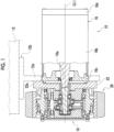
Fig. 1 is a side sectional view illustrating a power transmission device of a first embodiment. -
Fig. 2 is a side sectional view illustrating a speed reducer of the first embodiment. -
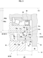
Fig. 3 is an enlarged view of a part ofFig. 2 . -
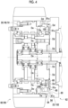
Fig. 4 is an explanatory view of a propagation location of a lubricant. - Hereinafter, embodiments will be described. The same reference numerals are added to the same components, and duplicated description will be omitted. In each drawing, components are omitted, enlarged, or reduced as appropriate for convenience of explanation. The drawings shall be viewed according to the orientation of the reference numerals.
-
Fig. 1 is referred to. Awheel drive device 10 is attached to avehicle body 12 such as a transport cart and is used to drive awheel 20. The transport cart is, for example, an automatic guided vehicle (AGV), an autonomous mobile robot (AMR), or the like. A use of thewheel drive device 10 of the present disclosure is not limited to the transport cart, and can be applied to various vehicles, such as a forklift and a self-propelled service robot. - The
wheel drive device 10 includes amotor 16, aspeed reducer 18 to which input rotation is input from anoutput shaft 16a of themotor 16, awheel 20 to which output rotation is output from thespeed reducer 18, and anattachment member 22 that is disposed between themotor 16 and thespeed reducer 18 and is attached to thevehicle body 12. Hereinafter, a direction along a rotation center line CL1 of thewheel 20 is referred to as an axial direction, and a radial direction and a circumferential direction having the rotation center line as the center of a circle are simply referred to as a radial direction and a circumferential direction. - The
motor 16 includes a tubular-shaped motor frame 16b and a pair ofcovers motor frame 16b. The pair ofcovers side cover 16c disposed on thespeed reducer 18 side and a counter load-side cover 16d disposed on a side opposite to thespeed reducer 18. - The
attachment member 22 forms an annular shape as a whole. Theattachment member 22 includes anattachment portion 22a for attaching to thevehicle body 12. Theattachment portion 22a in the present embodiment protrudes outwardly in the radial direction from themotor 16. Theattachment member 22 is attached to thevehicle body 12 by being connected to an attachedportion 12a by a bolt (not illustrated) in a state where theattachment portion 22a is abutted against the attachedportion 12a provided on thevehicle body 12. The attachedportion 12a may be provided on acomponent 12b to be attached to thevehicle body 12, or may be provided on thevehicle body 12 itself. -
Fig. 2 is referred to. Thespeed reducer 18 includes aninput shaft 24 to which input rotation is input from theoutput shaft 16a of themotor 16, areduction mechanism 26 that decelerates the input rotation transmitted from theinput shaft 24 and that converts the input rotation into output rotation, acasing 28 that accommodates thereduction mechanism 26, andcarriers casing 28 in the radial direction are provided. Theinput shaft 24 is connected to theoutput shaft 16a of themotor 16 using ajoint member 32 such as a spline joint. - The speed reducer 18 in the present embodiment is an eccentric oscillation type speed reducer. The
input shaft 24 of thespeed reducer 18 is a crankshaft having at least one (here, two)eccentric body 34. Eccentric phases of a plurality ofeccentric bodies 34 are offset from each other. Theinput shaft 24 and theeccentric body 34 may be either separate or integral. - The
reduction mechanism 26 of the eccentric oscillation type speed reducer includes anexternal gear 36 that oscillates by theeccentric body 34 and an internal gear 38 that meshes with theexternal gear 36. Theexternal gear 36 is individually provided corresponding to each of the plurality ofeccentric bodies 34, and is supported by theeccentric body 34 to be relatively rotatable through an eccentric body bearing 40. The internal gear 38 in the present embodiment includes an internal gearmain body 38a integrated with thecasing 28, and anouter pin 38b provided on an inner peripheral portion of the internal gearmain body 38a and constituting internal teeth. - The
carriers reduction mechanism 26. Thecarriers first carrier 30A disposed on one side in the axial direction and asecond carrier 30B disposed on the other side in the axial direction. Thecarriers carriers input shaft 24 through an input bearing 44. A main bearing 46 is disposed between thecasing 28 and thecarriers - The
speed reducer 18 described above includes anoutput member 48 to which output rotation is transmitted from thereduction mechanism 26 and outputting the output rotation, and afixing member 50 that rotates relative to theoutput member 48 when theoutput member 48 rotates. Thefixing member 50 is fixed to thevehicle body 12 through theattachment member 22. Theoutput member 48 in the present embodiment forms a tubular shape as a whole. Theoutput member 48 in the present embodiment is thecasing 28 and thefixing member 50 is thecarriers output member 48 may be either thecarrier 30A or thecarrier 30B, and thefixing member 50 may be thecasing 28. - The
wheel 20 travels on a traveling surface by being rotated by the output rotation output from theoutput member 48. For example, the traveling surface is a floor surface of a building, a rail, or the like. Thewheel 20 includes awheel member 52 that is connected to theoutput member 48 by using bolts or the like, and aground contact member 54 that is attached to an outer peripheral portion of thewheel member 52. Thewheel member 52 forms a tubular shape as a whole. Theground contact member 54 contacts the traveling surface when thewheel 20 travels. Theground contact member 54 in the present embodiment is a tire. Specific examples of theground contact member 54 are not particularly limited, and in addition, a roller for an omni wheel, a roller for a mecanum wheel, or the like may be used. - The
attachment member 22 functions as an adapter that connects themotor 16 and the speed reducer 18. Theattachment member 22 is connected to a flange portion (not illustrated) provided on a load-side cover 16c of themotor 16 using a bolt (not illustrated). Theattachment member 22 is connected to thefixing member 50 of thespeed reducer 18 using a bolt B. Theattachment member 22 is connected to thefixing member 50 in a state in which a side surface portion of theattachment member 22 is abutted against a side surface portion of thefixing member 50. Accordingly, theattachment member 22 is attached to thevehicle body 12 in a state in which each of themotor 16 and thespeed reducer 18 is supported. Theattachment member 22 is provided with a through-hole 22b that penetrates in the axial direction, and theoutput shaft 16a of themotor 16 and theinput shaft 24 of thespeed reducer 18 are inserted through the through-hole 22b. - The
attachment member 22 and themotor 16 include a motor-side spigotjoint portion 56 in which a first innerperipheral spigot surface 56a and a first outerperipheral spigot surface 56b are spigot-fitted. In the present embodiment, the first innerperipheral spigot surface 56a is provided on theattachment member 22, and the first outerperipheral spigot surface 56b is provided on the load-side cover 16c of themotor 16, but the reverse is also possible. Theattachment member 22 and the fixingmember 50 of thespeed reducer 18 include a speed reducer-side spigotjoint portion 58 in which a second innerperipheral spigot surface 58a and a second outerperipheral spigot surface 58b are spigot-fitted. In the present embodiment, the second innerperipheral spigot surface 58a is provided on the fixingmember 50 and the second outerperipheral spigot surface 58b is provided on theattachment member 22, but the reverse is also possible. - An operation of the
wheel drive device 10 described above will be described. In a case where the input rotation is input from themotor 16 to theinput shaft 24 of thespeed reducer 18, thereduction mechanism 26 operates. In a case where thereduction mechanism 26 operates, the output rotation decelerated with respect to the input rotation from thereduction mechanism 26 is transmitted to theoutput member 48. In a case where the output rotation is transmitted to theoutput member 48, thewheel 20 rotates together with theoutput member 48, and thewheel 20 travels on the traveling surface. - In a case where the eccentric oscillation
type speed reducer 18 is used as in the present embodiment, in a case where the input shaft 24 (crankshaft) rotates, theeccentric body 34 causes theexternal gear 36 to oscillate so that the center of theexternal gear 36 rotates around a rotation center line CL1 of theoutput member 48. In a case where theexternal gear 36 is oscillated, meshing positions of theexternal gear 36 and the internal gear 38 change in the circumferential direction. Accordingly, each time theinput shaft 24 rotates once, one of theexternal gear 36 and the internal gear 38 (here, the internal gear 38) rotates by a difference in the number of teeth between theexternal gear 36 and the internal gear 38. The axial rotation component is transmitted to theoutput member 48 as output rotation. - The
wheel drive device 10 described above includes arotating body 60 including thewheel 20, a fixedbody 62 that rotates relative to therotating body 60 when therotating body 60 rotates, and aseal member 68 that is disposed between therotating body 60 and the fixedbody 62 and that seals a sealingspace 66 containing alubricant 64. In the present embodiment, the rotatingbody 60 is thewheel 20 and the output member 48 (casing 28), and the fixedbody 62 is the fixing member 50 (carriers attachment member 22. - The sealing
space 66 is provided as an internal space of thewheel drive device 10. In the sealingspace 66 in the present embodiment, thereduction mechanism 26 of thespeed reducer 18 is accommodated and is provided at least at a location surrounded by thecasing 28 andcarriers space 66 in the present embodiment is sealed by aseal cover 70 that closes a counter motor-side opening portion of the tubular-shapedcasing 28 and anoil seal 16e that is disposed between theoutput shaft 16a of themotor 16 and the load-side cover 16c, in addition to theseal member 68. Thelubricant 64 is used for lubricating thereduction mechanism 26. Thelubricant 64 in the present embodiment is a lubricating oil, but may be grease or the like. - The
seal member 68 in the present embodiment is disposed between thecasing 28 which is a part of therotating body 60 and thesecond carrier 30B which is a part of the fixedbody 62. Theseal member 68 is a contact type seal such as a lip seal and an O-ring, and is a lip seal in this case. Theseal member 68 is composed of an elastic body such as rubber. -
Figs. 2 and3 are referred to. Thewheel drive device 10 includes anoil receiving member 80 that receives thelubricant 64 that has leaked beyond theseal member 68. Leakage beyond theseal member 68 as used herein means that thelubricant 64 leaks outward from the sealingspace 66 containing thelubricant 64 through the location where theseal member 68 is disposed. - The
oil receiving member 80 is provided on theattachment member 22 which is a part of the fixedbody 62. Theoil receiving member 80 in the present embodiment is integrally molded as a part of the same member as a mating member 82 (here, the attachment member 22) to which theoil receiving member 80 is provided, but it may be provided separately from the mating member 82. - The
oil receiving member 80 in the present embodiment includes anaxial wall portion 80a that extends in the axial direction from the mating member 82 in which theoil receiving member 80 is provided, and anouter wall portion 80b that protrudes inwardly in the radial direction from an outer end portion of theaxial wall portion 80a. Theoil receiving member 80 is provided to protrude in the axial direction from the mating member 82 as a whole. - At least a part of the
oil receiving member 80 is disposed inside an axial recessedportion 84 formed in one of therotating body 60 and the fixed body 62 (here, the rotating body 60). Hereinafter, one of therotating body 60 and the fixedbody 62 in which the axial recessedportion 84 is formed is referred to as a recessed portion forming body 86. The axial recessedportion 84 is formed outwardly in the radial direction from theseal member 68 in the recessed portion forming body 86. The axial recessedportion 84 is recessed from a side surface portion of the recessed portion forming body 86 toward one side in the axial direction (here, a counter motor side), and is continuous in an annular shape. The axial recessedportion 84 forms aradial gap 84c between anupper surface portion 84a and alower surface portion 84b of the axial recessedportion 84, and theoil receiving member 80 is disposed in theradial gap 84c. The axial recessedportion 84 in the present embodiment is formed between theoutput member 48 and thewheel member 52, which are a part of therotating body 60. - The
oil receiving member 80 includes a receiving recessedportion 88 having a concave shape for receiving thelubricant 64. The receiving recessedportion 88 in the present embodiment is formed inside theaxial wall portion 80a and theouter wall portion 80b. The receiving recessedportion 88 in the present embodiment is configured as an annularly continuous groove portion. The receiving recessedportion 88 forms anoil reservoir 90 that stores thelubricant 64 received by theoil receiving member 80. Theoil reservoir 90 in the present embodiment is provided below a lower end position Pa at an inner peripheral end portion of theouter wall portion 80b of theoil receiving member 80. - The receiving recessed
portion 88 includes abottom surface portion 88a and a pair ofside surface portions bottom surface portion 88a in the axial direction. The pair ofside surface portions inner surface portion 88b on the mating member 82, which is provided integrally with theoil receiving member 80, and anouter surface portion 88c on the side opposite to the mating member 82. In the present embodiment, theinner surface portion 88b is composed of the mating member 82, and theouter surface portion 88c is composed of theoil receiving member 80. As described above, the receiving recessedportion 88 of theoil receiving member 80 may be at least partially constituted by theoil receiving member 80, and partially constituted by the mating member 82. - The
wheel drive device 10 includes alubricant propagation member 91 through which thelubricant 64 that has leaked from theseal member 68 propagates. InFig. 3 , a propagation path of thelubricant 64 is schematically indicated by an arrow Da. Thelubricant propagation member 91 is acasing 28 and forms the above-described axial recessedportion 84 in the present embodiment. Thelubricant 64 that has leaked from theseal member 68 propagates through an outer surface portion of thelubricant propagation member 91 by at least its own weight. Thelubricant propagation member 91 includes, as a propagation location of thelubricant 64, anouter surface portion 91a located outwardly in the radial direction from theseal member 68 and anaxial surface portion 91c that extends inwardly in the axial direction from an outerperipheral edge portion 91b of theouter surface portion 91a. Theaxial surface portion 91c is provided with theupper surface portion 84a of the axial recessedportion 84 forming theradial gap 84c. Theoil receiving member 80 is disposed below the propagation location ofsuch lubricant 64, and can receive thelubricant 64 dripping from the propagation location. - The
lubricant propagation member 91 includes aguide portion 92 provided on theaxial surface portion 91c that is a position facing theoil receiving member 80 inwardly in the radial direction. Theguide portion 92 includes a largeouter diameter portion 92a provided on theaxial surface portion 91c and a smallouter diameter portion 92b provided on theaxial surface portion 91c inwardly in the axial direction from the largeouter diameter portion 92a. An outer diameter R92b of the smallouter diameter portion 92b is smaller than an outer diameter R92a of the largeouter diameter portion 92a. Theguide portion 92 in the present embodiment is configured by providing a recessed portion in theaxial surface portion 91c at a location of the smallouter diameter portion 92b. In addition, it may be configured by providing a protrusion at a location of theaxial surface portion 91c that becomes the largeouter diameter portion 92a, or may be configured by gradually reducing the outer diameter of theaxial surface portion 91c inwardly in the axial direction. In the present embodiment, the largeouter diameter portion 92a and the smallouter diameter portion 92b constituting theguide portion 92 are provided in a range over the entire circumference of theaxial surface portion 91c. - When the
lubricant 64 tries to propagate inwardly in the axial direction in theaxial surface portion 91c of thelubricant propagation member 91, it becomes difficult for thelubricant 64 to climb from the largeouter diameter portion 92a to the smallouter diameter portion 92b. Therefore, thelubricant 64 can be held by the largeouter diameter portion 92a of theguide portion 92 by blocking the propagation of thelubricant 64 in the largeouter diameter portion 92a of theguide portion 92. Theguide portion 92 can guide thelubricant 64 held by itself to theoil receiving member 80 in a direction Db by separating thelubricant 64 by its own weight, rotation, or the like. That is, theguide portion 92 of thelubricant propagation member 91 holds thelubricant 64 by blocking the propagation of thelubricant 64 at a position facing theoil receiving member 80 inwardly in the radial direction, and guides the heldlubricant 64 to theoil receiving member 80 by separating it. - Accordingly, it is possible to reduce the amount of the
lubricant 64 that tries to pass inwardly in the axial direction at a position that faces theoil receiving member 80 inwardly in the radial direction in thelubricant propagation member 91. In this example, thelubricant 64 trying to pass inwardly in the axial direction leaks into theexternal space 94 after passing through theupper surface portion 84a of the axial recessedportion 84, the bottom portion, thelower surface portion 84b, and the side surface portion of thewheel member 52, as indicated by an arrow Dc. That is, after passing through the position facing theoil receiving member 80 inwardly in the radial direction in thelubricant propagation member 91, thelubricant 64 leaks into theexternal space 94 after passing through an outer surface portion of a member (here, the wheel member 52) that is integrated with thelubricant propagation member 91 below theoil receiving member 80. By providing the above-describedguide portion 92, it is possible to reduce the amount of thelubricant 64 leaking into theexternal space 94. -
Fig. 4 is referred to. InFig. 4 , hatching is applied to a part of apropagation location 100 of thelubricant 64 that has leaked from theseal member 68. Thelubricant propagation member 91 in the present embodiment is a part of therotating body 60. Therefore, thelubricant 64 that has leaked from theseal member 68 propagates to a range continuous in the circumferential direction from the propagation location of thelubricant 64 by its own weight in thelubricant propagation member 91, by the rotation of thelubricant propagation member 91. Thepropagation location 100 of thelubricant 64 due to this rotation includes theouter surface portion 91a and anaxial surface portion 91c of thelubricant propagation member 91 located outwardly in the radial direction from theseal member 68. Theoil receiving member 80 of the present embodiment is provided in an annular shape so as to surround thepropagation location 100 of thelubricant 64 which is a part of thelubricant propagation member 91 from the outside in the radial direction. Accordingly, when thelubricant 64 splashes from thepropagation location 100 of thelubricant 64 of thelubricant propagation member 91 by the rotation of therotating body 60, it is possible to receive thelubricant 64 by theoil receiving member 80. As a result, leakage of the splashedlubricant 64 into theexternal space 94 can be suppressed. - Effects of the
wheel drive device 10 described above will be described. - At least a part of the
oil receiving member 80 is disposed inside the axial recessedportion 84 formed in one of therotating body 60 and the fixedbody 62. Therefore, as compared with a case where the axial recessedportion 84 is not formed in the recessed portion forming body 86, an axial dimension L80 (refer toFig. 3 ) of theoil receiving member 80 can be increased by the amount of theoil receiving member 80 disposed in the axial recessedportion 84, and the storage volume of the lubricant can be increased accordingly. Here, the ability to increase the storage volume of the lubricant means that the volume of theoil reservoir 90 of theoil receiving member 80 can be increased. Further, as compared with a case where the axial dimension L90 of the sameoil receiving member 80 is secured without forming the axial recessedportion 84 in the recessed portion forming body 86, the axial dimension of the entirewheel drive device 10 can be reduced. As a result, it is possible to reduce the axial dimensions of the entirewheel drive device 10 while increasing the storage volume of the lubricant by theoil receiving member 80. - The
oil receiving member 80 is provided on theattachment member 22. Accordingly, a part of the heat generated by themotor 16 and thespeed reducer 18 and transmitted to theattachment member 22 can be transmitted to theoil receiving member 80 from theattachment member 22. Therefore, a surface area contributing to heat radiation to the air can be increased by the amount of theoil receiving member 80. As a result, the amount of heat that is released to the air directly from theattachment member 22 and theoil receiving member 80 without passing through thevehicle body 12 can be increased, and the heat radiation of thewheel drive device 10 can be improved. In addition, since the amount of heat transmitted from theattachment member 22 to thevehicle body 12 out of the heat transmitted to theattachment member 22 can be reduced, the influence on thevehicle body 12 due to the heat generated by themotor 16 or the like can be reduced. - As described above, the
oil receiving member 80 in the present embodiment functions as a heat radiating member for receiving a part of the heat transmitted to theattachment member 22 and radiating the heat to theexternal space 94. From such a viewpoint, a part of theoil receiving member 80 may be provided at a position exposed to theexternal space 94 when viewed from the radial direction. Here, a part of theoil receiving member 80 means theaxial wall portion 80a of theoil receiving member 80 in the present embodiment. - The
oil receiving member 80 is provided on the fixedbody 62. Accordingly, theoil receiving member 80 can be maintained in a stationary state when thewheel 20 rotates, so that a state in which thelubricant 64 is stored can be stably maintained by theoil receiving member 80 without spilling. - Next, other features of the
wheel drive device 10 will be described.Fig. 4 is referred to. Thewheel drive device 10 includes a facing member 102 that is disposed to face thelubricant propagation member 91 that is a part of therotating body 60 in the axial direction. The facing member 102 in the present embodiment is theattachment member 22 provided with theoil receiving member 80, and is a part of the fixedbody 62. The facing member 102 is also disposed to face not only thelubricant propagation member 91 but also theseal member 68 in the axial direction. Thebottom surface portion 88a of theoil receiving member 80 is inclined inwardly in the radial direction toward the facing member 102 in the axial direction. Advantages regarding the above will be described. - A case where the
lubricant 64 which is splashed upward from theaxial surface portion 91c of thelubricant propagation member 91 by the rotation of therotating body 60 above theseal member 68 is received by theoil receiving member 80 is considered. InFig. 4 , two propagation paths of thelubricant 64, which is splashed upward in this way, are schematically indicated by arrows Dd and De. The propagation path in the present embodiment is indicated by the arrow Dd, and the propagation path in the reference embodiment is indicated by the arrow De. A solid line arrow inFig. 4 indicates that thelubricant 64 propagates at a location visible inFig. 4 , and a broken line arrow indicates that thelubricant 64 propagates at a hidden location inFig. 4 . - The structure (not illustrated) of the reference embodiment assumes a case where the
bottom surface portion 88a of theoil receiving member 80 is not inclined and is parallel to the axial direction. In this case, a case where thelubricant 64, which is received by thebottom surface portion 88a of theoil receiving member 80 and is splashed upward, propagates on a side opposite to the facing member 102 in the axial direction is considered. In this case, as illustrated by the arrow De inFig. 4 , as thelubricant 64 drips downward from theouter surface portion 88c of theoil receiving member 80, thelubricant 64 returns to theaxial surface portion 91c of thelubricant propagation member 91. As a result, after propagating from an upper portion to a lower portion of theaxial surface portion 91c of thelubricant propagation member 91, thelubricant 64 propagates below theoil receiving member 80, and a risk that thelubricant 64 leaks to theexternal space 94 is increased. - In this regard, according to the present embodiment, the
bottom surface portion 88a of theoil receiving member 80 is inclined to approach inwardly in the radial direction toward the facing member 102. Therefore, as illustrated by the arrow Dd, thelubricant 64 received by thebottom surface portion 88a of theoil receiving member 80 above theseal member 68 can be guided to a side of the facing member 102 by its own weight. Thelubricant 64 guided to the side of the facing member 102 in this manner propagates downward on the side surface portion of the facing member 102, and then is guided to theoil reservoir 90 of theoil receiving member 80. That is, in a case where thelubricant 64, which is splashed upward, is received by thebottom surface portion 88a of theoil receiving member 80, after propagating the side surface portion of the facing member 102, it can be guided to theoil reservoir 90 of theoil receiving member 80. As a result, thelubricant 64, which is splashed upward, propagates to the side opposite to the facing member 102, so that it is possible to avoid a situation in which thelubricant 64 leaks to theexternal space 94. - Next, modification examples of each component described so far will be described.
- Specific examples of the
speed reducer 18 are not particularly limited, and various reduction mechanisms can be applied, such as a bending meshing type speed reducer, a simple planetary gear type speed reducer, a traction drive, or the like, in addition to the eccentric oscillation type speed reducer. The type of the eccentric oscillation type speed reducer is not particularly limited. As an example of this, the center crank type in which the crankshaft (input shaft 24) is disposed on the rotation center line of thewheel 20 has been described in the embodiment. In addition to this, it may be a distribution type in which a plurality of crankshafts are disposed at positions offset in the radial direction from the rotation center line of thewheel 20. The type of the bending meshing type speed reducer is not particularly limited, and may be, for example, a cup type having one internal gear, a silk hat type, or the like in addition to a tubular type having two internal gears. - The axial recessed
portion 84 may be formed in any one of therotating body 60 and the fixedbody 62. The axial recessedportion 84 may be formed in the fixedbody 62 in place of therotating body 60. It is assumed that, for example, a case where the axial recessedportion 84 is formed in theattachment member 22 that is the fixedbody 62. In addition to this, the axial recessedportion 84 may be formed in only one of theoutput member 48 and thewheel member 52, which are therotating body 60. In addition, theoutput member 48 and thewheel member 52 may be integrally molded, in addition to a case where theoutput member 48 and thewheel member 52 are separately provided as in the embodiment. - Specific examples of the position and shape of the
oil receiving member 80 are not particularly limited as long as the lubricant that has leaked beyond theseal member 68 can be received. For example, theoil receiving member 80 may be disposed only below the propagation location of thelubricant 64 by its own weight in thelubricant propagation member 91. In this case, for example, theoil receiving member 80 may form a continuous arc shape in a circumferential range of about half a circumference below the propagation location of thelubricant 64 by its own weight. Thebottom surface portion 88a of theoil receiving member 80 may not be inclined, or may be inclined outwardly in the radial direction toward the facing member 102. - An example in which the mating member 82 provided with the
oil receiving member 80 is a part of the fixedbody 62 has been described, but the mating member 82 may be a part of therotating body 60. For example, it is assumed that theoil receiving member 80 is provided in any one of theoutput member 48 and thewheel member 52, which are a part of therotating body 60. - The
lubricant propagation member 91 may be a member integrated with the casing 28 (for example, the wheel member 52) in place of thecasing 28. In addition, in a case where thelubricant propagation member 91 is thecasing 28, thecasing 28 may be a part of either therotating body 60 or the fixedbody 62. - The above-described embodiments and modification examples are examples. The technical ideas that abstract the embodiments and modification examples should not be construed as being limited to the contents of the embodiments and modification examples. Many design changes such as the change, addition, and deletion of components can be made with respect to the contents of the embodiments and modification examples. In the above-described embodiments, the contents for which such design changes are possible are emphasized by adding the notation "embodiment". However, design changes are allowed even in the contents in which there is no such notation. Hatching applied to the cross section of the drawing does not limit the material of the hatched object. Structures and numerical values as mentioned in the embodiments and modification examples naturally include those that can be regarded as the same when manufacturing errors and the like are taken into consideration.
- Any combination of the above components is also valid. For example, the modification examples may be combined with any description of the embodiments and modification examples. A component composed of a single member in an embodiment may be composed of a plurality of members. Similarly, a component composed of a plurality of members in an embodiment may be composed of a single member.
-
- 10
- wheel drive device
- 12
- vehicle body
- 16
- motor
- 18
- speed reducer
- 20
- wheel
- 22
- attachment member
- 48
- output member
- 52
- wheel member
- 60
- rotating body
- 62
- fixed body
- 64
- lubricant
- 66
- sealing space
- 68
- seal member
- 80
- oil receiving member
- 84
- axial recessed portion
- 92
- guide portion
- 102
- facing member
Claims (8)
- A wheel drive device (10) that drives a wheel (20), comprising:a rotating body (60) including the wheel (20);a fixed body (62) that rotates relative to the rotating body (60);a seal member (68) that is disposed between the rotating body (60) and the fixed body (62) and that seals a sealing space (66) containing a lubricant (64); andan oil receiving member (80) that receives the lubricant (64) that has leaked beyond the seal member (68),wherein at least a part of the oil receiving member (80) is disposed inside an axial recessed portion (84) formed in one of the rotating body (60) and the fixed body (62) .
- The wheel drive device (10) according to claim 1, further comprising:
a guide portion (92) that is provided at a position facing the oil receiving member (80) inwardly in a radial direction and that guides the lubricant (64) to the oil receiving member (80). - The wheel drive device (10) according to claim 1 or 2,
wherein the oil receiving member (80) is provided in an annular shape. - The wheel drive device (10) according to claim 3, further comprising:a lubricant propagation member (91) through which the lubricant (64) that has leaked from the seal member (68) propagates and which is a part of the rotating body (60),wherein the oil receiving member (80) is provided in the annular shape so as to surround a part of the lubricant propagation member (91).
- The wheel drive device (10) according to claim 4, further comprising:a facing member (102) that is disposed to face the lubricant propagation member (91) in an axial direction and that is provided with the oil receiving member (80),wherein a bottom surface portion (88a) of the oil receiving member (80) is inclined inwardly in a radial direction toward the facing member (102) in the axial direction.
- The wheel drive device (10) according to claim 1 or 2, further comprising:an attachment member (22) that is disposed between a motor and a speed reducer and that is attached to a vehicle body,wherein the oil receiving member (80) is provided on the attachment member (22).
- The wheel drive device (10) according to claim 1 or 2,
wherein the oil receiving member (80) is provided on the fixed body (62). - The wheel drive device (10) according to claim 1 or 2,wherein the rotating body (60) includes a wheel member (52) and an output member (48) that rotates integrally with the wheel member (52), andthe axial recessed portion (84) is provided between the wheel member (52) and the output member (48).
Applications Claiming Priority (1)
| Application Number | Priority Date | Filing Date | Title |
|---|---|---|---|
| JP2022110249A JP2024008403A (en) | 2022-07-08 | 2022-07-08 | wheel drive device |
Publications (2)
| Publication Number | Publication Date |
|---|---|
| EP4303465A1 true EP4303465A1 (en) | 2024-01-10 |
| EP4303465B1 EP4303465B1 (en) | 2025-03-12 |
Family
ID=86776327
Family Applications (1)
| Application Number | Title | Priority Date | Filing Date |
|---|---|---|---|
| EP23179225.0A Active EP4303465B1 (en) | 2022-07-08 | 2023-06-14 | Wheel drive device |
Country Status (2)
| Country | Link |
|---|---|
| EP (1) | EP4303465B1 (en) |
| JP (1) | JP2024008403A (en) |
Cited By (1)
| Publication number | Priority date | Publication date | Assignee | Title |
|---|---|---|---|---|
| US20250251038A1 (en) * | 2024-02-02 | 2025-08-07 | Nabtesco Corporation | Speed reducer and industrial machine |
Citations (3)
| Publication number | Priority date | Publication date | Assignee | Title |
|---|---|---|---|---|
| JP2016178787A (en) * | 2015-03-19 | 2016-10-06 | 住友重機械工業株式会社 | Rotating device |
| JP2018144778A (en) | 2017-03-09 | 2018-09-20 | 住友重機械工業株式会社 | Wheel driving apparatus |
| US20200096089A1 (en) * | 2016-03-29 | 2020-03-26 | Mitsubishi Electric Corporation | Planetary gear device and vehicle wheel drive device |
Family Cites Families (2)
| Publication number | Priority date | Publication date | Assignee | Title |
|---|---|---|---|---|
| JP7431066B2 (en) * | 2020-03-13 | 2024-02-14 | 住友重機械工業株式会社 | wheel drive device |
| KR102730315B1 (en) * | 2020-06-05 | 2024-11-13 | 가부시키가이샤 하모닉 드라이브 시스템즈 | Lubricant sealing structure, wave gear device and actuator |
-
2022
- 2022-07-08 JP JP2022110249A patent/JP2024008403A/en active Pending
-
2023
- 2023-06-14 EP EP23179225.0A patent/EP4303465B1/en active Active
Patent Citations (3)
| Publication number | Priority date | Publication date | Assignee | Title |
|---|---|---|---|---|
| JP2016178787A (en) * | 2015-03-19 | 2016-10-06 | 住友重機械工業株式会社 | Rotating device |
| US20200096089A1 (en) * | 2016-03-29 | 2020-03-26 | Mitsubishi Electric Corporation | Planetary gear device and vehicle wheel drive device |
| JP2018144778A (en) | 2017-03-09 | 2018-09-20 | 住友重機械工業株式会社 | Wheel driving apparatus |
Cited By (1)
| Publication number | Priority date | Publication date | Assignee | Title |
|---|---|---|---|---|
| US20250251038A1 (en) * | 2024-02-02 | 2025-08-07 | Nabtesco Corporation | Speed reducer and industrial machine |
Also Published As
| Publication number | Publication date |
|---|---|
| EP4303465B1 (en) | 2025-03-12 |
| JP2024008403A (en) | 2024-01-19 |
Similar Documents
| Publication | Publication Date | Title |
|---|---|---|
| US11131365B2 (en) | Reducer | |
| EP2273140B1 (en) | Device with seals | |
| EP4303465B1 (en) | Wheel drive device | |
| US7896554B2 (en) | Propeller shaft for motor vehicle | |
| CN104443091A (en) | Supporting chain wheel for track-laying vehicle | |
| US7823696B2 (en) | Gear unit and lubricating oil splash preventing method | |
| JP2003181788A (en) | Robot joint structure | |
| JP2010164168A (en) | Travelling unit for construction machine | |
| JP2003127682A (en) | Vehicle drive system | |
| CN204355183U (en) | For the holder sprocket wheel of tracklaying vehicle | |
| AU2014250626A1 (en) | System and method for unified torque transmission and rotary sealing | |
| KR0157132B1 (en) | Flexible gear joint | |
| US11339868B2 (en) | Vehicle driving apparatus | |
| EP4303051A1 (en) | Wheel drive device | |
| US10837538B2 (en) | Transmission and driving apparatus provided with transmission | |
| CN215360772U (en) | Axle assembly and all-terrain vehicle | |
| JP2011149513A (en) | Power transmission device | |
| JP7431066B2 (en) | wheel drive device | |
| US20240133468A1 (en) | Propeller shaft | |
| KR101215001B1 (en) | Oil seal and rotary device | |
| KR20200135162A (en) | Internal-pressure rise prevention structure of speed reducer | |
| US12631257B2 (en) | Seal device and construction machine | |
| JP7302420B2 (en) | Vehicle drive transmission device | |
| KR102783858B1 (en) | Seal for In-wheel Motor and Sealing Device for In-wheel Motor Including The Seal | |
| US20250035162A1 (en) | Seal device and construction machine |
Legal Events
| Date | Code | Title | Description |
|---|---|---|---|
| PUAI | Public reference made under article 153(3) epc to a published international application that has entered the european phase |
Free format text: ORIGINAL CODE: 0009012 |
|
| STAA | Information on the status of an ep patent application or granted ep patent |
Free format text: STATUS: REQUEST FOR EXAMINATION WAS MADE |
|
| STAA | Information on the status of an ep patent application or granted ep patent |
Free format text: STATUS: EXAMINATION IS IN PROGRESS |
|
| 17P | Request for examination filed |
Effective date: 20230614 |
|
| AK | Designated contracting states |
Kind code of ref document: A1 Designated state(s): AL AT BE BG CH CY CZ DE DK EE ES FI FR GB GR HR HU IE IS IT LI LT LU LV MC ME MK MT NL NO PL PT RO RS SE SI SK SM TR |
|
| 17Q | First examination report despatched |
Effective date: 20231218 |
|
| RIC1 | Information provided on ipc code assigned before grant |
Ipc: F16H 57/02 20120101ALN20240820BHEP Ipc: B60K 17/04 20060101ALI20240820BHEP Ipc: F16J 15/3204 20160101ALI20240820BHEP Ipc: B60K 7/00 20060101ALI20240820BHEP Ipc: F16J 15/3208 20160101ALI20240820BHEP Ipc: F16H 57/04 20100101ALI20240820BHEP Ipc: F16H 57/029 20120101ALI20240820BHEP Ipc: F16H 49/00 20060101ALI20240820BHEP Ipc: F16H 1/32 20060101AFI20240820BHEP |
|
| GRAP | Despatch of communication of intention to grant a patent |
Free format text: ORIGINAL CODE: EPIDOSNIGR1 |
|
| STAA | Information on the status of an ep patent application or granted ep patent |
Free format text: STATUS: GRANT OF PATENT IS INTENDED |
|
| INTG | Intention to grant announced |
Effective date: 20241002 |
|
| GRAS | Grant fee paid |
Free format text: ORIGINAL CODE: EPIDOSNIGR3 |
|
| GRAA | (expected) grant |
Free format text: ORIGINAL CODE: 0009210 |
|
| STAA | Information on the status of an ep patent application or granted ep patent |
Free format text: STATUS: THE PATENT HAS BEEN GRANTED |
|
| AK | Designated contracting states |
Kind code of ref document: B1 Designated state(s): AL AT BE BG CH CY CZ DE DK EE ES FI FR GB GR HR HU IE IS IT LI LT LU LV MC ME MK MT NL NO PL PT RO RS SE SI SK SM TR |
|
| REG | Reference to a national code |
Ref country code: GB Ref legal event code: FG4D |
|
| REG | Reference to a national code |
Ref country code: CH Ref legal event code: EP |
|
| REG | Reference to a national code |
Ref country code: DE Ref legal event code: R096 Ref document number: 602023002367 Country of ref document: DE |
|
| REG | Reference to a national code |
Ref country code: IE Ref legal event code: FG4D |
|
| PG25 | Lapsed in a contracting state [announced via postgrant information from national office to epo] |
Ref country code: RS Free format text: LAPSE BECAUSE OF FAILURE TO SUBMIT A TRANSLATION OF THE DESCRIPTION OR TO PAY THE FEE WITHIN THE PRESCRIBED TIME-LIMIT Effective date: 20250612 |
|
| PG25 | Lapsed in a contracting state [announced via postgrant information from national office to epo] |
Ref country code: FI Free format text: LAPSE BECAUSE OF FAILURE TO SUBMIT A TRANSLATION OF THE DESCRIPTION OR TO PAY THE FEE WITHIN THE PRESCRIBED TIME-LIMIT Effective date: 20250312 |
|
| PGFP | Annual fee paid to national office [announced via postgrant information from national office to epo] |
Ref country code: DE Payment date: 20250408 Year of fee payment: 3 |
|
| PG25 | Lapsed in a contracting state [announced via postgrant information from national office to epo] |
Ref country code: ES Free format text: LAPSE BECAUSE OF FAILURE TO SUBMIT A TRANSLATION OF THE DESCRIPTION OR TO PAY THE FEE WITHIN THE PRESCRIBED TIME-LIMIT Effective date: 20250312 |
|
| REG | Reference to a national code |
Ref country code: LT Ref legal event code: MG9D |
|
| PG25 | Lapsed in a contracting state [announced via postgrant information from national office to epo] |
Ref country code: NO Free format text: LAPSE BECAUSE OF FAILURE TO SUBMIT A TRANSLATION OF THE DESCRIPTION OR TO PAY THE FEE WITHIN THE PRESCRIBED TIME-LIMIT Effective date: 20250612 |
|
| PG25 | Lapsed in a contracting state [announced via postgrant information from national office to epo] |
Ref country code: HR Free format text: LAPSE BECAUSE OF FAILURE TO SUBMIT A TRANSLATION OF THE DESCRIPTION OR TO PAY THE FEE WITHIN THE PRESCRIBED TIME-LIMIT Effective date: 20250312 |
|
| REG | Reference to a national code |
Ref country code: NL Ref legal event code: MP Effective date: 20250312 |
|
| PG25 | Lapsed in a contracting state [announced via postgrant information from national office to epo] |
Ref country code: LV Free format text: LAPSE BECAUSE OF FAILURE TO SUBMIT A TRANSLATION OF THE DESCRIPTION OR TO PAY THE FEE WITHIN THE PRESCRIBED TIME-LIMIT Effective date: 20250312 |
|
| PG25 | Lapsed in a contracting state [announced via postgrant information from national office to epo] |
Ref country code: GR Free format text: LAPSE BECAUSE OF FAILURE TO SUBMIT A TRANSLATION OF THE DESCRIPTION OR TO PAY THE FEE WITHIN THE PRESCRIBED TIME-LIMIT Effective date: 20250613 Ref country code: BG Free format text: LAPSE BECAUSE OF FAILURE TO SUBMIT A TRANSLATION OF THE DESCRIPTION OR TO PAY THE FEE WITHIN THE PRESCRIBED TIME-LIMIT Effective date: 20250312 |
|
| REG | Reference to a national code |
Ref country code: AT Ref legal event code: MK05 Ref document number: 1775224 Country of ref document: AT Kind code of ref document: T Effective date: 20250312 |
|
| PG25 | Lapsed in a contracting state [announced via postgrant information from national office to epo] |
Ref country code: NL Free format text: LAPSE BECAUSE OF FAILURE TO SUBMIT A TRANSLATION OF THE DESCRIPTION OR TO PAY THE FEE WITHIN THE PRESCRIBED TIME-LIMIT Effective date: 20250312 |
|
| PG25 | Lapsed in a contracting state [announced via postgrant information from national office to epo] |
Ref country code: SE Free format text: LAPSE BECAUSE OF FAILURE TO SUBMIT A TRANSLATION OF THE DESCRIPTION OR TO PAY THE FEE WITHIN THE PRESCRIBED TIME-LIMIT Effective date: 20250312 |
|
| PG25 | Lapsed in a contracting state [announced via postgrant information from national office to epo] |
Ref country code: SM Free format text: LAPSE BECAUSE OF FAILURE TO SUBMIT A TRANSLATION OF THE DESCRIPTION OR TO PAY THE FEE WITHIN THE PRESCRIBED TIME-LIMIT Effective date: 20250312 |
|
| PG25 | Lapsed in a contracting state [announced via postgrant information from national office to epo] |
Ref country code: PT Free format text: LAPSE BECAUSE OF FAILURE TO SUBMIT A TRANSLATION OF THE DESCRIPTION OR TO PAY THE FEE WITHIN THE PRESCRIBED TIME-LIMIT Effective date: 20250714 |
|
| PG25 | Lapsed in a contracting state [announced via postgrant information from national office to epo] |
Ref country code: PL Free format text: LAPSE BECAUSE OF FAILURE TO SUBMIT A TRANSLATION OF THE DESCRIPTION OR TO PAY THE FEE WITHIN THE PRESCRIBED TIME-LIMIT Effective date: 20250312 |
|
| PGFP | Annual fee paid to national office [announced via postgrant information from national office to epo] |
Ref country code: IT Payment date: 20250630 Year of fee payment: 3 |
|
| PG25 | Lapsed in a contracting state [announced via postgrant information from national office to epo] |
Ref country code: AT Free format text: LAPSE BECAUSE OF FAILURE TO SUBMIT A TRANSLATION OF THE DESCRIPTION OR TO PAY THE FEE WITHIN THE PRESCRIBED TIME-LIMIT Effective date: 20250312 |
|
| PG25 | Lapsed in a contracting state [announced via postgrant information from national office to epo] |
Ref country code: CZ Free format text: LAPSE BECAUSE OF FAILURE TO SUBMIT A TRANSLATION OF THE DESCRIPTION OR TO PAY THE FEE WITHIN THE PRESCRIBED TIME-LIMIT Effective date: 20250312 Ref country code: EE Free format text: LAPSE BECAUSE OF FAILURE TO SUBMIT A TRANSLATION OF THE DESCRIPTION OR TO PAY THE FEE WITHIN THE PRESCRIBED TIME-LIMIT Effective date: 20250312 |
|
| PG25 | Lapsed in a contracting state [announced via postgrant information from national office to epo] |
Ref country code: RO Free format text: LAPSE BECAUSE OF FAILURE TO SUBMIT A TRANSLATION OF THE DESCRIPTION OR TO PAY THE FEE WITHIN THE PRESCRIBED TIME-LIMIT Effective date: 20250312 |
|
| PG25 | Lapsed in a contracting state [announced via postgrant information from national office to epo] |
Ref country code: SK Free format text: LAPSE BECAUSE OF FAILURE TO SUBMIT A TRANSLATION OF THE DESCRIPTION OR TO PAY THE FEE WITHIN THE PRESCRIBED TIME-LIMIT Effective date: 20250312 |
|
| PG25 | Lapsed in a contracting state [announced via postgrant information from national office to epo] |
Ref country code: IS Free format text: LAPSE BECAUSE OF FAILURE TO SUBMIT A TRANSLATION OF THE DESCRIPTION OR TO PAY THE FEE WITHIN THE PRESCRIBED TIME-LIMIT Effective date: 20250712 |
|
| REG | Reference to a national code |
Ref country code: DE Ref legal event code: R097 Ref document number: 602023002367 Country of ref document: DE |
|
| PG25 | Lapsed in a contracting state [announced via postgrant information from national office to epo] |
Ref country code: DK Free format text: LAPSE BECAUSE OF FAILURE TO SUBMIT A TRANSLATION OF THE DESCRIPTION OR TO PAY THE FEE WITHIN THE PRESCRIBED TIME-LIMIT Effective date: 20250312 |
|
| PLBE | No opposition filed within time limit |
Free format text: ORIGINAL CODE: 0009261 |
|
| STAA | Information on the status of an ep patent application or granted ep patent |
Free format text: STATUS: NO OPPOSITION FILED WITHIN TIME LIMIT |
|
| REG | Reference to a national code |
Ref country code: CH Ref legal event code: L10 Free format text: ST27 STATUS EVENT CODE: U-0-0-L10-L00 (AS PROVIDED BY THE NATIONAL OFFICE) Effective date: 20260121 |
|
| PG25 | Lapsed in a contracting state [announced via postgrant information from national office to epo] |
Ref country code: MC Free format text: LAPSE BECAUSE OF FAILURE TO SUBMIT A TRANSLATION OF THE DESCRIPTION OR TO PAY THE FEE WITHIN THE PRESCRIBED TIME-LIMIT Effective date: 20250312 |
|
| PG25 | Lapsed in a contracting state [announced via postgrant information from national office to epo] |
Ref country code: LU Free format text: LAPSE BECAUSE OF NON-PAYMENT OF DUE FEES Effective date: 20250614 |
|
| 26N | No opposition filed |
Effective date: 20251215 |
|
| REG | Reference to a national code |
Ref country code: BE Ref legal event code: MM Effective date: 20250630 |
|
| PG25 | Lapsed in a contracting state [announced via postgrant information from national office to epo] |
Ref country code: IE Free format text: LAPSE BECAUSE OF NON-PAYMENT OF DUE FEES Effective date: 20250614 |
|
| PG25 | Lapsed in a contracting state [announced via postgrant information from national office to epo] |
Ref country code: BE Free format text: LAPSE BECAUSE OF NON-PAYMENT OF DUE FEES Effective date: 20250630 |
|
| PG25 | Lapsed in a contracting state [announced via postgrant information from national office to epo] |
Ref country code: FR Free format text: LAPSE BECAUSE OF NON-PAYMENT OF DUE FEES Effective date: 20250630 |