EP4303427A1 - On-vehicle hydrogen supply apparatus - Google Patents
On-vehicle hydrogen supply apparatus Download PDFInfo
- Publication number
- EP4303427A1 EP4303427A1 EP23181258.7A EP23181258A EP4303427A1 EP 4303427 A1 EP4303427 A1 EP 4303427A1 EP 23181258 A EP23181258 A EP 23181258A EP 4303427 A1 EP4303427 A1 EP 4303427A1
- Authority
- EP
- European Patent Office
- Prior art keywords
- cover
- hydrogen
- hydrogen supply
- vehicle
- space
- Prior art date
- Legal status (The legal status is an assumption and is not a legal conclusion. Google has not performed a legal analysis and makes no representation as to the accuracy of the status listed.)
- Granted
Links
Images

Classifications
-
- F—MECHANICAL ENGINEERING; LIGHTING; HEATING; WEAPONS; BLASTING
- F17—STORING OR DISTRIBUTING GASES OR LIQUIDS
- F17C—VESSELS FOR CONTAINING OR STORING COMPRESSED, LIQUEFIED OR SOLIDIFIED GASES; FIXED-CAPACITY GAS-HOLDERS; FILLING VESSELS WITH, OR DISCHARGING FROM VESSELS, COMPRESSED, LIQUEFIED, OR SOLIDIFIED GASES
- F17C7/00—Methods or apparatus for discharging liquefied, solidified, or compressed gases from pressure vessels, not covered by another subclass
- F17C7/02—Discharging liquefied gases
- F17C7/04—Discharging liquefied gases with change of state, e.g. vaporisation
-
- F—MECHANICAL ENGINEERING; LIGHTING; HEATING; WEAPONS; BLASTING
- F02—COMBUSTION ENGINES; HOT-GAS OR COMBUSTION-PRODUCT ENGINE PLANTS
- F02M—SUPPLYING COMBUSTION ENGINES IN GENERAL WITH COMBUSTIBLE MIXTURES OR CONSTITUENTS THEREOF
- F02M21/00—Apparatus for supplying engines with non-liquid fuels, e.g. gaseous fuels stored in liquid form
- F02M21/02—Apparatus for supplying engines with non-liquid fuels, e.g. gaseous fuels stored in liquid form for gaseous fuels
- F02M21/0203—Apparatus for supplying engines with non-liquid fuels, e.g. gaseous fuels stored in liquid form for gaseous fuels characterised by the type of gaseous fuel
- F02M21/0206—Non-hydrocarbon fuels, e.g. hydrogen, ammonia or carbon monoxide
-
- B—PERFORMING OPERATIONS; TRANSPORTING
- B60—VEHICLES IN GENERAL
- B60K—ARRANGEMENT OR MOUNTING OF PROPULSION UNITS OR OF TRANSMISSIONS IN VEHICLES; ARRANGEMENT OR MOUNTING OF PLURAL DIVERSE PRIME-MOVERS IN VEHICLES; AUXILIARY DRIVES FOR VEHICLES; INSTRUMENTATION OR DASHBOARDS FOR VEHICLES; ARRANGEMENTS IN CONNECTION WITH COOLING, AIR INTAKE, GAS EXHAUST OR FUEL SUPPLY OF PROPULSION UNITS IN VEHICLES
- B60K15/00—Arrangement in connection with fuel supply of combustion engines or other fuel consuming energy converters, e.g. fuel cells; Mounting or construction of fuel tanks
- B60K15/03—Fuel tanks
- B60K15/063—Arrangement of tanks
- B60K15/067—Mounting of tanks
- B60K15/07—Mounting of tanks of gas tanks
-
- F—MECHANICAL ENGINEERING; LIGHTING; HEATING; WEAPONS; BLASTING
- F02—COMBUSTION ENGINES; HOT-GAS OR COMBUSTION-PRODUCT ENGINE PLANTS
- F02M—SUPPLYING COMBUSTION ENGINES IN GENERAL WITH COMBUSTIBLE MIXTURES OR CONSTITUENTS THEREOF
- F02M21/00—Apparatus for supplying engines with non-liquid fuels, e.g. gaseous fuels stored in liquid form
- F02M21/02—Apparatus for supplying engines with non-liquid fuels, e.g. gaseous fuels stored in liquid form for gaseous fuels
- F02M21/0218—Details on the gaseous fuel supply system, e.g. tanks, valves, pipes, pumps, rails, injectors or mixers
- F02M21/0221—Fuel storage reservoirs, e.g. cryogenic tanks
-
- F—MECHANICAL ENGINEERING; LIGHTING; HEATING; WEAPONS; BLASTING
- F02—COMBUSTION ENGINES; HOT-GAS OR COMBUSTION-PRODUCT ENGINE PLANTS
- F02M—SUPPLYING COMBUSTION ENGINES IN GENERAL WITH COMBUSTIBLE MIXTURES OR CONSTITUENTS THEREOF
- F02M21/00—Apparatus for supplying engines with non-liquid fuels, e.g. gaseous fuels stored in liquid form
- F02M21/02—Apparatus for supplying engines with non-liquid fuels, e.g. gaseous fuels stored in liquid form for gaseous fuels
- F02M21/0218—Details on the gaseous fuel supply system, e.g. tanks, valves, pipes, pumps, rails, injectors or mixers
- F02M21/023—Valves; Pressure or flow regulators in the fuel supply or return system
- F02M21/0242—Shut-off valves; Check valves; Safety valves; Pressure relief valves
-
- F—MECHANICAL ENGINEERING; LIGHTING; HEATING; WEAPONS; BLASTING
- F02—COMBUSTION ENGINES; HOT-GAS OR COMBUSTION-PRODUCT ENGINE PLANTS
- F02M—SUPPLYING COMBUSTION ENGINES IN GENERAL WITH COMBUSTIBLE MIXTURES OR CONSTITUENTS THEREOF
- F02M21/00—Apparatus for supplying engines with non-liquid fuels, e.g. gaseous fuels stored in liquid form
- F02M21/02—Apparatus for supplying engines with non-liquid fuels, e.g. gaseous fuels stored in liquid form for gaseous fuels
- F02M21/0218—Details on the gaseous fuel supply system, e.g. tanks, valves, pipes, pumps, rails, injectors or mixers
- F02M21/0287—Details on the gaseous fuel supply system, e.g. tanks, valves, pipes, pumps, rails, injectors or mixers characterised by the transition from liquid to gaseous phase ; Injection in liquid phase; Cooling and low temperature storage
-
- F—MECHANICAL ENGINEERING; LIGHTING; HEATING; WEAPONS; BLASTING
- F02—COMBUSTION ENGINES; HOT-GAS OR COMBUSTION-PRODUCT ENGINE PLANTS
- F02M—SUPPLYING COMBUSTION ENGINES IN GENERAL WITH COMBUSTIBLE MIXTURES OR CONSTITUENTS THEREOF
- F02M21/00—Apparatus for supplying engines with non-liquid fuels, e.g. gaseous fuels stored in liquid form
- F02M21/02—Apparatus for supplying engines with non-liquid fuels, e.g. gaseous fuels stored in liquid form for gaseous fuels
- F02M21/0218—Details on the gaseous fuel supply system, e.g. tanks, valves, pipes, pumps, rails, injectors or mixers
- F02M21/029—Arrangement on engines or vehicle bodies; Conversion to gaseous fuel supply systems
-
- F—MECHANICAL ENGINEERING; LIGHTING; HEATING; WEAPONS; BLASTING
- F02—COMBUSTION ENGINES; HOT-GAS OR COMBUSTION-PRODUCT ENGINE PLANTS
- F02M—SUPPLYING COMBUSTION ENGINES IN GENERAL WITH COMBUSTIBLE MIXTURES OR CONSTITUENTS THEREOF
- F02M21/00—Apparatus for supplying engines with non-liquid fuels, e.g. gaseous fuels stored in liquid form
- F02M21/02—Apparatus for supplying engines with non-liquid fuels, e.g. gaseous fuels stored in liquid form for gaseous fuels
- F02M21/0218—Details on the gaseous fuel supply system, e.g. tanks, valves, pipes, pumps, rails, injectors or mixers
- F02M21/0293—Safety devices; Fail-safe measures
-
- B—PERFORMING OPERATIONS; TRANSPORTING
- B60—VEHICLES IN GENERAL
- B60K—ARRANGEMENT OR MOUNTING OF PROPULSION UNITS OR OF TRANSMISSIONS IN VEHICLES; ARRANGEMENT OR MOUNTING OF PLURAL DIVERSE PRIME-MOVERS IN VEHICLES; AUXILIARY DRIVES FOR VEHICLES; INSTRUMENTATION OR DASHBOARDS FOR VEHICLES; ARRANGEMENTS IN CONNECTION WITH COOLING, AIR INTAKE, GAS EXHAUST OR FUEL SUPPLY OF PROPULSION UNITS IN VEHICLES
- B60K15/00—Arrangement in connection with fuel supply of combustion engines or other fuel consuming energy converters, e.g. fuel cells; Mounting or construction of fuel tanks
- B60K15/03—Fuel tanks
- B60K2015/03309—Tanks specially adapted for particular fuels
- B60K2015/03315—Tanks specially adapted for particular fuels for hydrogen
-
- F—MECHANICAL ENGINEERING; LIGHTING; HEATING; WEAPONS; BLASTING
- F02—COMBUSTION ENGINES; HOT-GAS OR COMBUSTION-PRODUCT ENGINE PLANTS
- F02M—SUPPLYING COMBUSTION ENGINES IN GENERAL WITH COMBUSTIBLE MIXTURES OR CONSTITUENTS THEREOF
- F02M21/00—Apparatus for supplying engines with non-liquid fuels, e.g. gaseous fuels stored in liquid form
- F02M21/02—Apparatus for supplying engines with non-liquid fuels, e.g. gaseous fuels stored in liquid form for gaseous fuels
- F02M21/06—Apparatus for de-liquefying, e.g. by heating
-
- F—MECHANICAL ENGINEERING; LIGHTING; HEATING; WEAPONS; BLASTING
- F17—STORING OR DISTRIBUTING GASES OR LIQUIDS
- F17C—VESSELS FOR CONTAINING OR STORING COMPRESSED, LIQUEFIED OR SOLIDIFIED GASES; FIXED-CAPACITY GAS-HOLDERS; FILLING VESSELS WITH, OR DISCHARGING FROM VESSELS, COMPRESSED, LIQUEFIED, OR SOLIDIFIED GASES
- F17C2201/00—Vessel construction, in particular geometry, arrangement or size
- F17C2201/01—Shape
- F17C2201/0104—Shape cylindrical
- F17C2201/0109—Shape cylindrical with exteriorly curved end-piece
-
- F—MECHANICAL ENGINEERING; LIGHTING; HEATING; WEAPONS; BLASTING
- F17—STORING OR DISTRIBUTING GASES OR LIQUIDS
- F17C—VESSELS FOR CONTAINING OR STORING COMPRESSED, LIQUEFIED OR SOLIDIFIED GASES; FIXED-CAPACITY GAS-HOLDERS; FILLING VESSELS WITH, OR DISCHARGING FROM VESSELS, COMPRESSED, LIQUEFIED, OR SOLIDIFIED GASES
- F17C2201/00—Vessel construction, in particular geometry, arrangement or size
- F17C2201/05—Size
- F17C2201/056—Small (<1 m3)
-
- F—MECHANICAL ENGINEERING; LIGHTING; HEATING; WEAPONS; BLASTING
- F17—STORING OR DISTRIBUTING GASES OR LIQUIDS
- F17C—VESSELS FOR CONTAINING OR STORING COMPRESSED, LIQUEFIED OR SOLIDIFIED GASES; FIXED-CAPACITY GAS-HOLDERS; FILLING VESSELS WITH, OR DISCHARGING FROM VESSELS, COMPRESSED, LIQUEFIED, OR SOLIDIFIED GASES
- F17C2203/00—Vessel construction, in particular walls or details thereof
- F17C2203/06—Materials for walls or layers thereof; Properties or structures of walls or their materials
- F17C2203/0634—Materials for walls or layers thereof
- F17C2203/0658—Synthetics
- F17C2203/0663—Synthetics in form of fibers or filaments
- F17C2203/0673—Polymers
-
- F—MECHANICAL ENGINEERING; LIGHTING; HEATING; WEAPONS; BLASTING
- F17—STORING OR DISTRIBUTING GASES OR LIQUIDS
- F17C—VESSELS FOR CONTAINING OR STORING COMPRESSED, LIQUEFIED OR SOLIDIFIED GASES; FIXED-CAPACITY GAS-HOLDERS; FILLING VESSELS WITH, OR DISCHARGING FROM VESSELS, COMPRESSED, LIQUEFIED, OR SOLIDIFIED GASES
- F17C2205/00—Vessel construction, in particular mounting arrangements, attachments or identifications means
- F17C2205/01—Mounting arrangements
- F17C2205/0103—Exterior arrangements
- F17C2205/0111—Boxes
-
- F—MECHANICAL ENGINEERING; LIGHTING; HEATING; WEAPONS; BLASTING
- F17—STORING OR DISTRIBUTING GASES OR LIQUIDS
- F17C—VESSELS FOR CONTAINING OR STORING COMPRESSED, LIQUEFIED OR SOLIDIFIED GASES; FIXED-CAPACITY GAS-HOLDERS; FILLING VESSELS WITH, OR DISCHARGING FROM VESSELS, COMPRESSED, LIQUEFIED, OR SOLIDIFIED GASES
- F17C2205/00—Vessel construction, in particular mounting arrangements, attachments or identifications means
- F17C2205/03—Fluid connections, filters, valves, closure means or other attachments
- F17C2205/0302—Fittings, valves, filters, or components in connection with the gas storage device
- F17C2205/0323—Valves
-
- F—MECHANICAL ENGINEERING; LIGHTING; HEATING; WEAPONS; BLASTING
- F17—STORING OR DISTRIBUTING GASES OR LIQUIDS
- F17C—VESSELS FOR CONTAINING OR STORING COMPRESSED, LIQUEFIED OR SOLIDIFIED GASES; FIXED-CAPACITY GAS-HOLDERS; FILLING VESSELS WITH, OR DISCHARGING FROM VESSELS, COMPRESSED, LIQUEFIED, OR SOLIDIFIED GASES
- F17C2221/00—Handled fluid, in particular type of fluid
- F17C2221/01—Pure fluids
- F17C2221/012—Hydrogen
-
- F—MECHANICAL ENGINEERING; LIGHTING; HEATING; WEAPONS; BLASTING
- F17—STORING OR DISTRIBUTING GASES OR LIQUIDS
- F17C—VESSELS FOR CONTAINING OR STORING COMPRESSED, LIQUEFIED OR SOLIDIFIED GASES; FIXED-CAPACITY GAS-HOLDERS; FILLING VESSELS WITH, OR DISCHARGING FROM VESSELS, COMPRESSED, LIQUEFIED, OR SOLIDIFIED GASES
- F17C2223/00—Handled fluid before transfer, i.e. state of fluid when stored in the vessel or before transfer from the vessel
- F17C2223/01—Handled fluid before transfer, i.e. state of fluid when stored in the vessel or before transfer from the vessel characterised by the phase
- F17C2223/0107—Single phase
- F17C2223/013—Single phase liquid
-
- F—MECHANICAL ENGINEERING; LIGHTING; HEATING; WEAPONS; BLASTING
- F17—STORING OR DISTRIBUTING GASES OR LIQUIDS
- F17C—VESSELS FOR CONTAINING OR STORING COMPRESSED, LIQUEFIED OR SOLIDIFIED GASES; FIXED-CAPACITY GAS-HOLDERS; FILLING VESSELS WITH, OR DISCHARGING FROM VESSELS, COMPRESSED, LIQUEFIED, OR SOLIDIFIED GASES
- F17C2265/00—Effects achieved by gas storage or gas handling
- F17C2265/06—Fluid distribution
- F17C2265/066—Fluid distribution for feeding engines for propulsion
-
- F—MECHANICAL ENGINEERING; LIGHTING; HEATING; WEAPONS; BLASTING
- F17—STORING OR DISTRIBUTING GASES OR LIQUIDS
- F17C—VESSELS FOR CONTAINING OR STORING COMPRESSED, LIQUEFIED OR SOLIDIFIED GASES; FIXED-CAPACITY GAS-HOLDERS; FILLING VESSELS WITH, OR DISCHARGING FROM VESSELS, COMPRESSED, LIQUEFIED, OR SOLIDIFIED GASES
- F17C2270/00—Applications
- F17C2270/01—Applications for fluid transport or storage
- F17C2270/0165—Applications for fluid transport or storage on the road
- F17C2270/0168—Applications for fluid transport or storage on the road by vehicles
-
- F—MECHANICAL ENGINEERING; LIGHTING; HEATING; WEAPONS; BLASTING
- F17—STORING OR DISTRIBUTING GASES OR LIQUIDS
- F17C—VESSELS FOR CONTAINING OR STORING COMPRESSED, LIQUEFIED OR SOLIDIFIED GASES; FIXED-CAPACITY GAS-HOLDERS; FILLING VESSELS WITH, OR DISCHARGING FROM VESSELS, COMPRESSED, LIQUEFIED, OR SOLIDIFIED GASES
- F17C2270/00—Applications
- F17C2270/01—Applications for fluid transport or storage
- F17C2270/0165—Applications for fluid transport or storage on the road
- F17C2270/0184—Fuel cells
-
- Y—GENERAL TAGGING OF NEW TECHNOLOGICAL DEVELOPMENTS; GENERAL TAGGING OF CROSS-SECTIONAL TECHNOLOGIES SPANNING OVER SEVERAL SECTIONS OF THE IPC; TECHNICAL SUBJECTS COVERED BY FORMER USPC CROSS-REFERENCE ART COLLECTIONS [XRACs] AND DIGESTS
- Y02—TECHNOLOGIES OR APPLICATIONS FOR MITIGATION OR ADAPTATION AGAINST CLIMATE CHANGE
- Y02E—REDUCTION OF GREENHOUSE GAS [GHG] EMISSIONS, RELATED TO ENERGY GENERATION, TRANSMISSION OR DISTRIBUTION
- Y02E60/00—Enabling technologies; Technologies with a potential or indirect contribution to GHG emissions mitigation
- Y02E60/30—Hydrogen technology
- Y02E60/32—Hydrogen storage
Definitions
- the present disclosure relates to a configuration of an on-vehicle hydrogen supply apparatus that supplies hydrogen gas to a hydrogen engine for driving a vehicle.
- JP 2007- 516384 A discloses an on-vehicle fuel tank composed of an inner casing that contains liquid hydrogen, and an outer casing that supports the inner casing via a vacuum heat-insulation layer.
- PATENT DOCUMENT 1 JP 2007-516384 A
- the vehicles running on liquid hydrogen are equipped with a liquid hydrogen tank, a vaporizer that vaporizes liquid hydrogen, and a hydrogen supply unit that fills a space with vaporized hydrogen gas and supplies the filled hydrogen gas to a fuel cell, hydrogen engine, or the like. It is desired to prevent or reduce damage to such a hydrogen supply unit in the event of a vehicle collision.
- An object of the present disclosure is therefore to prevent or reduce damage to the hydrogen supply unit in the event of a vehicle collision.
- An on-vehicle hydrogen supply apparatus includes a hydrogen supply unit that includes a liquid hydrogen tank, a vaporizer that vaporizes liquid hydrogen, and a pressure chamber that is filled with vaporized hydrogen gas and supplies the filled hydrogen gas to a hydrogen engine for driving a vehicle, and supplies the hydrogen gas vaporized from the liquid hydrogen to the hydrogen engine.
- the on-vehicle hydrogen supply apparatus also includes a cover that houses the hydrogen supply unit.
- the hydrogen supply unit is housed in the cover and mounted on the vehicle, and this makes it possible to prevent or reduce damage to the hydrogen supply unit in the event of a vehicle collision.
- the cover for the hydrogen supply unit may include a partition plate that separates an interior space into a first space that houses the liquid hydrogen tank and a second space that houses the vaporizer and the pressure chamber.
- the partition plate is located between the liquid hydrogen tank and the pressure chamber and between the liquid hydrogen tank and the vaporizer to separate the space that houses them, and this makes it possible to prevent contact between the liquid hydrogen tank and the pressure chamber and between the liquid hydrogen tank and the vaporizer in the event of a vehicle collision, thereby preventing or reducing damage thereto.
- the hydrogen supply unit may include a pressure reducing valve that is located above the vaporizer in the second space and reduces the pressure of the hydrogen gas filled in the pressure chamber, and the cover may include a stay that extends into the second space and supports an upper part of the pressure reducing valve.
- the cover may include a lower cover that houses a lower part of the liquid hydrogen tank and has, at its rear side, a pedestal on which the vaporizer is mounted, an upper cover that is assembled to the upper side of the lower cover so as to cover an upper part of the liquid hydrogen tank and houses the pressure chamber therein, and a rear cover that is attached to the upper side of the pedestal of the lower cover so as to cover the vaporizer mounted on the pedestal and is connected to a rear end of the upper cover.
- the cover is composed of the lower cover, the upper cover, and the rear cover, and this allows the cover to house the hydrogen supply unit easily even if the shape of the hydrogen supply unit is complicated.
- the liquid hydrogen tank has a cylindrical shape
- the partition plate has a flat section that is attached to the upper side of the lower cover and covers the upper part of the liquid hydrogen tank, and a curved section that curves downward from the flat section along an outer circumference of the liquid hydrogen tank and extends to a front end of the pedestal of the lower cover.
- the first space is a space on the lower side of the partition plate
- the second space is a space on the upper and rear sides of the partition plate.
- the pressure chamber may be located between the partition plate and a ceiling plate of the upper cover, and the vaporizer may be located between the partition plate and the rear cover.
- the pressure chamber and the vaporizer are located between the partition plate and the upper cover or the rear cover, and this makes it possible to prevent direct transmission of impact force to the pressure chamber and the vaporizer in the event of a vehicle collision, thereby preventing or reducing damage to the pressure chamber and the vaporizer.
- the hydrogen supply unit may include a pressure reducing valve that is located above the vaporizer in the second space and reduces the pressure of the hydrogen gas filled in the pressure chamber, and the rear cover may include a stay that extends into the second space and supports an upper part of the pressure reducing valve.
- the upper cover, the lower cover, and the rear cover may be made of CFRP.
- the partition plate may also be made of CFRP.
- arrows "FR,” “UP,” and “RH” respectively represent the front side, the upper side, and the right side of the on-vehicle hydrogen supply apparatus 100.
- the directions opposite to the arrows "FR,” “UP,” and “RH” respectively represent the rear side, the lower side, and the left side of the on-vehicle hydrogen supply apparatus 100.
- the on-vehicle hydrogen supply apparatus 100 is mounted on a vehicle such that its front side is at the front side of the vehicle (traveling direction), its upper side is at the upper side of the vehicle, and its right side is at the right side of the vehicle. Therefore, when the on-vehicle hydrogen supply apparatus 100 is mounted on the vehicle, its front side, upper side, and right side are respectively located at the front side, the upper side, and the right side of the vehicle.
- the on-vehicle hydrogen supply apparatus 100 is composed of a hydrogen supply unit 60 that supplies hydrogen gas vaporized from liquid hydrogen to a hydrogen engine for driving the vehicle, and a cover 10 that houses the hydrogen supply unit 60.
- the cover 10 is composed of a lower cover 20, an upper cover 30, and a rear cover 40.
- the hydrogen supply unit 60 is composed of a liquid hydrogen tank 61, a vaporizer 62, a pressure chamber 63, a pressure reducing valve 65, a liquid hydrogen pump 71, and pipes 72 to 76.
- the liquid hydrogen tank 61 is an insulated tank that contains low-temperature liquid hydrogen.
- the liquid hydrogen tank 61 is a cylindrical tank with dish-shaped mirror plates attached to both ends.
- the liquid hydrogen pump 71 is located inside the liquid hydrogen tank 61 and applies pressure to liquid hydrogen to transfer it to the vaporizer 62.
- the vaporizer 62 vaporizes liquid hydrogen to hydrogen gas by heat exchange between liquid hydrogen flowing from the liquid hydrogen tank 61 and helium gas heated by a heater (not shown). Helium gas enters the vaporizer 62 through a helium gas inlet pipe 66 and returns to the heater through a helium gas return pipe 67 (see FIG. 1 ).
- the pressure chamber 63 is filled with hydrogen gas that flows from the vaporizer 62. Hydrogen gas filled in the pressure chamber 63 is supplied to the hydrogen engine through the pressure reducing valve 65.
- the pressure chamber 63 is a cylindrical chamber with full hemispherical mirror plates attached to both ends. The mirror plate on the right side of the pressure chamber 63 has a pipe connection seat 64 attached thereto.
- the pressure reducing valve 65 has a valve body 65a, and an actuator 65b that protrudes upward. The pressure reducing valve 65 reduces the pressure of the high pressure hydrogen gas flowing from the pressure chamber 63 to the supply pressure of hydrogen gas to be supplied to the hydrogen engine.
- the liquid hydrogen pump 71 in the liquid hydrogen tank 61 is connected to the vaporizer 62 via the liquid hydrogen discharge pipe 72 and the vaporizer inlet pipe 73.
- the vaporizer 62 is connected to the pressure chamber 63 via the hydrogen gas filler pipe 74.
- the pressure chamber 63 is connected to the pressure reducing valve 65 via the hydrogen gas outlet pipe 75. After the pressure reducing valve 65 reduces the pressure of hydrogen gas, the resulting hydrogen gas is supplied to the hydrogen engine through the hydrogen gas supply pipe 76.
- the cover 10 is composed of the lower cover 20, the upper cover 30, and the rear cover 40. First, the external shapes of the lower cover 20, the upper cover 30, and the rear cover 40 will be described.
- the lower cover 20 has a square box shape with an open top surrounded by a bottom plate 21, a lower front plate 22, a lower rear plate 23, and lower right and left side plates 24.
- the height of the lower rear plate 23 is lower than the height of the lower front plate 22.
- Upper ends of the lower right and left side plates 24 slope downward from the front to the rear.
- a plate-like pedestal 27 is attached to the rear side of the lower rear plate 23 of the lower cover 20 so as to protrude rearward. Rear parts of the lower right and left side plates 24 extend onto the pedestal 27 and are connected to right and left ends of the pedestal 27.
- the lower cover 20, the upper cover 30, the rear cover 40, and the pedestal 27 are made of carbon fiber reinforced plastics (hereinafter referred to as CFRP).
- the upper cover 30 is composed of a ceiling plate 31, an upper front plate 32, and upper right and left side plates 33.
- the height of the upper right and left side plates 33 is higher in the rear than in the front, and lower ends of the upper right and left side plates 33 slope downward from the front to the rear.
- the upper cover 30 is assembled to the upper side of the lower cover 20 such that a lower end of the upper front plate 32 comes into contact with an upper end of the lower front plate 22 of the lower cover 20 and lower ends of the upper right and left side plates 33 come into contact with upper ends of the lower right and left side plates 24.
- the rear cover 40 is composed of a rear ceiling plate 41, a rear plate 42, and rear right and left side plates 43. Like the rear parts of the lower right and left side plates 24 of the lower cover 20, lower ends of the rear right and left side plates 43 slope downward from the front to the rear.
- the rear cover 40 is assembled to the lower cover 20 and the upper cover 30 such that a front end of the rear ceiling plate 41 comes into contact with a rear end of the ceiling plate 31, front ends of the rear right and left side plates 43 come into contact with rear ends of the upper right and left side plates 33 and the lower right and left side plates 24, lower ends of the rear right and left side plates 43 come into contact with upper ends of portions of the lower right and left side plates 24 that extend above the pedestal 27, and that a lower end of the rear plate 42 comes into contact with an upper end of the pedestal 27.
- the cover 10 which has a square box shape with a portion protruding rearward, as shown in FIG. 1 .
- a tank receiving plate 26 is mounted inside the lower cover 20.
- the tank receiving plate 26 has a cylindrical surface to receive the liquid hydrogen tank 61.
- the tank receiving plate 26 is connected to the lower right and left side plates 24 and to the bottom plate 21 via a plurality of supporting members (not shown).
- an upper front end of the tank receiving plate 26 and the upper end of the lower front plate 22 are connected by a connecting plate 25.
- the tank receiving plate 26 receives the lower part of the liquid hydrogen tank 61.
- the vaporizer 62 is mounted on the pedestal 27 on the rear side of the tank receiving plate 26. Furthermore, a groove-shaped frame 28 with an open bottom is mounted above the pedestal 27 so as to straddle the vaporizer 62.
- the pressure reducing valve 65 is mounted on the frame 28.
- the rear cover 40 has a stay 45 protruding forward from the rear plate 42 inside the rear cover 40.
- the stay 45 supports the actuator 65b of the pressure reducing valve 65 when the rear cover 40 is assembled to the lower cover 20 and the upper cover 30.
- a partition plate 50 is provided on the upper side of the lower cover 20.
- the partition plate 50 has a flat section 51, a curved section 52, and a post 55.
- the flat section 51 is a section attached to the upper side of the lower cover 20 and covers the upper part of the liquid hydrogen tank 61.
- the curved section 52 is a section that curves downward from the flat section 51 along the outer circumference of the liquid hydrogen tank 61 and extends to the front end of the pedestal 27 of the lower cover 20.
- the width of the partition plate 50 in the right-and-left direction is smaller than the widths of the inner surfaces of the upper cover 30 and the lower cover 20 in the right-and-left direction.
- the post 55 connects the front end of the flat section 51 to the connecting plate 25 of the lower cover 20 to support the flat section 51.
- the lower end of the curved section 52 is connected to the lower rear plate 23 of the lower cover 20.
- a base 53 for supporting the pressure chamber 63 is mounted on the upper surface of the curved section 52 of the partition plate 50.
- the pressure chamber 63 is mounted on the upper side of the base 53.
- the liquid hydrogen tank 61 is received in the tank receiving plate 26 of the lower cover 20, as indicated by an arrow 91 in FIG. 4 .
- the partition plate 50 is attached to the connecting plate 25 and the lower rear plate 23 of the lower cover 20 so as to cover the top of the liquid hydrogen tank 61, as indicated by arrows 92 in FIG. 4 .
- the upper cover 30 is placed over the partition plate 50 and the pressure chamber 63 from above as indicated by arrows 95 in FIG. 4 and is assembled to the lower cover 20 such that its lower ends come into contact with the upper ends of the lower cover 20.
- the upper cover 30 covers the upper part of the liquid hydrogen tank 61 and houses the pressure chamber 63 therein.
- the rear cover 40 is assembled to the lower cover 20 and the upper cover 30 so as to cover the vaporizer 62 and the pressure reducing valve 65 from above and behind, as indicated by arrows 96 in FIG. 4 .
- the lower cover 20 when the components constituting the hydrogen supply unit 60 are housed in the interior space of the cover 10, the lower cover 20, the lower half of the upper cover 30, and the partition plate 50 define a first space 81.
- the first space 81 is a space located on the lower side of the partition plate 50.
- the first space 81 houses the liquid hydrogen tank 61.
- the partition plate 50, the pedestal 27, the upper half of the upper cover 30, and the rear cover 40 define a second space 82.
- the second space 82 is a space on the upper and rear sides of the partition plate 50.
- the second space 82 houses the pressure chamber 63 and the vaporizer 62.
- the pressure chamber 63 is located between the partition plate 50 and the ceiling plate 31 of the upper cover 30.
- the vaporizer 62 and the pressure reducing valve 65 are located between the partition plate 50 and the rear plate 42 of the rear cover 40.
- the partition plate 50 separates the interior space of the cover 10 into the first space 81 that houses the liquid hydrogen tank 61 and the second space 82 that houses the vaporizer 62 and the pressure chamber 63.
- the stay 45 attached to the rear cover 40 fits into the circumference of the actuator 65b of the pressure reducing valve 65 to thereby support the actuator 65b in the front and back direction and the right and left direction.
- the on-vehicle hydrogen supply apparatus 100 is mounted on the vehicle with the hydrogen supply unit 60 housed in the cover 10, and this prevents or reduces damage to the hydrogen supply unit 60 in the event of a vehicle collision.
- the on-vehicle hydrogen supply apparatus 100 also has the partition plate 50 that separates the interior space of the cover 10 into the first space 81 where the liquid hydrogen tank 61 is housed and the second space 82 where the pressure chamber 63 and the vaporizer 62 are housed. This makes it possible to prevent contact between the liquid hydrogen tank 61 and the pressure chamber 63 and between the liquid hydrogen tank 61 and the vaporizer 62 in the event of a vehicle collision, thereby preventing or reducing damage thereto.
- the cover 10 is composed of the lower cover 20, the upper cover 30, and the rear cover 40, and this allows the cover 10 to house the hydrogen supply unit 60 even if the shape of the hydrogen supply unit 60 is complicated.
- the pressure chamber 63 and the vaporizer 62 are located between the partition plate 50 and the upper cover 30 or the rear cover 40, and this makes it possible to prevent direct transmission of impact force to the pressure chamber 63 and the vaporizer 62 in the event of a vehicle collision, thereby preventing or reducing damage to the pressure chamber 63 and the vaporizer 62.
- the stay 45 which is attached to the rear cover 40, supports the actuator 65b at the upper side of the pressure reducing valve 65 and thus can prevent or reduce damage to the pressure reducing valve 65 in the event of a vehicle collision.
- the lower cover 20, the upper cover 30, the rear cover 40, and the partition plate 50 are made of high-strength CFRP, and this makes it possible to effectively prevent or reduce damage to the hydrogen supply unit 60 in the event of a vehicle collision.
Landscapes
- Engineering & Computer Science (AREA)
- Chemical & Material Sciences (AREA)
- Mechanical Engineering (AREA)
- Combustion & Propulsion (AREA)
- General Engineering & Computer Science (AREA)
- General Chemical & Material Sciences (AREA)
- Oil, Petroleum & Natural Gas (AREA)
- Chemical Kinetics & Catalysis (AREA)
- Life Sciences & Earth Sciences (AREA)
- Sustainable Development (AREA)
- Sustainable Energy (AREA)
- Transportation (AREA)
- Filling Or Discharging Of Gas Storage Vessels (AREA)
- Cooling, Air Intake And Gas Exhaust, And Fuel Tank Arrangements In Propulsion Units (AREA)
Abstract
Description
- This application claims priority to
Japanese Patent Application No. 2022-107522 filed on July 4, 2022 - The present disclosure relates to a configuration of an on-vehicle hydrogen supply apparatus that supplies hydrogen gas to a hydrogen engine for driving a vehicle.
- In recent years, vehicles running on liquid hydrogen have been used.
JP 2007- 516384 A - PATENT DOCUMENT 1:
JP 2007-516384 A - The vehicles running on liquid hydrogen are equipped with a liquid hydrogen tank, a vaporizer that vaporizes liquid hydrogen, and a hydrogen supply unit that fills a space with vaporized hydrogen gas and supplies the filled hydrogen gas to a fuel cell, hydrogen engine, or the like. It is desired to prevent or reduce damage to such a hydrogen supply unit in the event of a vehicle collision.
- An object of the present disclosure is therefore to prevent or reduce damage to the hydrogen supply unit in the event of a vehicle collision.
- An on-vehicle hydrogen supply apparatus according to the present disclosure includes a hydrogen supply unit that includes a liquid hydrogen tank, a vaporizer that vaporizes liquid hydrogen, and a pressure chamber that is filled with vaporized hydrogen gas and supplies the filled hydrogen gas to a hydrogen engine for driving a vehicle, and supplies the hydrogen gas vaporized from the liquid hydrogen to the hydrogen engine. The on-vehicle hydrogen supply apparatus also includes a cover that houses the hydrogen supply unit.
- As such, the hydrogen supply unit is housed in the cover and mounted on the vehicle, and this makes it possible to prevent or reduce damage to the hydrogen supply unit in the event of a vehicle collision.
- In the on-vehicle hydrogen supply apparatus according to the present disclosure, the cover for the hydrogen supply unit may include a partition plate that separates an interior space into a first space that houses the liquid hydrogen tank and a second space that houses the vaporizer and the pressure chamber.
- As such, the partition plate is located between the liquid hydrogen tank and the pressure chamber and between the liquid hydrogen tank and the vaporizer to separate the space that houses them, and this makes it possible to prevent contact between the liquid hydrogen tank and the pressure chamber and between the liquid hydrogen tank and the vaporizer in the event of a vehicle collision, thereby preventing or reducing damage thereto.
- In the on-vehicle hydrogen supply apparatus according to the present disclosure, the hydrogen supply unit may include a pressure reducing valve that is located above the vaporizer in the second space and reduces the pressure of the hydrogen gas filled in the pressure chamber, and the cover may include a stay that extends into the second space and supports an upper part of the pressure reducing valve.
- This makes is possible to prevent oscillation of an upper end of the pressure reducing valve, which may otherwise cause damage to the pressure reducing valve in the event of a vehicle collision.
- In the on-vehicle hydrogen supply apparatus according to the present disclosure, the cover may include a lower cover that houses a lower part of the liquid hydrogen tank and has, at its rear side, a pedestal on which the vaporizer is mounted, an upper cover that is assembled to the upper side of the lower cover so as to cover an upper part of the liquid hydrogen tank and houses the pressure chamber therein, and a rear cover that is attached to the upper side of the pedestal of the lower cover so as to cover the vaporizer mounted on the pedestal and is connected to a rear end of the upper cover.
- As such, the cover is composed of the lower cover, the upper cover, and the rear cover, and this allows the cover to house the hydrogen supply unit easily even if the shape of the hydrogen supply unit is complicated.
- In the on-vehicle hydrogen supply apparatus according to the present disclosure, the liquid hydrogen tank has a cylindrical shape, and the partition plate has a flat section that is attached to the upper side of the lower cover and covers the upper part of the liquid hydrogen tank, and a curved section that curves downward from the flat section along an outer circumference of the liquid hydrogen tank and extends to a front end of the pedestal of the lower cover. The first space is a space on the lower side of the partition plate, and the second space is a space on the upper and rear sides of the partition plate. The pressure chamber may be located between the partition plate and a ceiling plate of the upper cover, and the vaporizer may be located between the partition plate and the rear cover.
- As such, the pressure chamber and the vaporizer are located between the partition plate and the upper cover or the rear cover, and this makes it possible to prevent direct transmission of impact force to the pressure chamber and the vaporizer in the event of a vehicle collision, thereby preventing or reducing damage to the pressure chamber and the vaporizer.
- In the on-vehicle hydrogen supply apparatus according to the present disclosure, the hydrogen supply unit may include a pressure reducing valve that is located above the vaporizer in the second space and reduces the pressure of the hydrogen gas filled in the pressure chamber, and the rear cover may include a stay that extends into the second space and supports an upper part of the pressure reducing valve.
- This makes it possible to prevent oscillation of an upper end of the pressure reducing valve which may cause damage to the pressure reducing valve in the event of a vehicle collision.
- In the on-vehicle hydrogen supply apparatus according to the present disclosure, the upper cover, the lower cover, and the rear cover may be made of CFRP. The partition plate may also be made of CFRP.
- By forming the covers and the partition plate from such a high-strength material, damage to the hydrogen supply unit housed in the cover can be effectively prevented or reduced in the event of a vehicle collision.
- According to the present disclosure, it is possible to prevent or reduce damage to the hydrogen supply unit in the event of a vehicle collision.
- An embodiment of the present disclosure will be described based on the following figures, wherein:
-
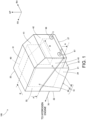
FIG. 1 is a perspective view of an on-vehicle hydrogen supply apparatus according to an embodiment viewed from the rear side; -
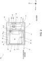
FIG. 2 is a plane view of the on-vehicle hydrogen supply apparatus shown inFIG. 1 viewed from above, with its upper cover removed, along A-A inFIG. 1 ; -
FIG. 3 is an elevated cross-sectional view of the on-vehicle hydrogen supply apparatus shown inFIG. 1 , taken along B-B inFIG. 1 ; and -
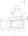
FIG. 4 is an exploded cross-sectional view of the on-vehicle hydrogen supply apparatus shown inFIG. 1 . - Hereinafter, an on-vehicle
hydrogen supply apparatus 100 according to an embodiment will be described with reference to the drawings. In the drawings, arrows "FR," "UP," and "RH" respectively represent the front side, the upper side, and the right side of the on-vehiclehydrogen supply apparatus 100. The directions opposite to the arrows "FR," "UP," and "RH" respectively represent the rear side, the lower side, and the left side of the on-vehiclehydrogen supply apparatus 100. Hereinafter, when the description is given simply using front and rear, right and left, and up and down directions, they respectively indicate front and rear in the front-and-rear direction, right and left in the right-and-left direction, and up and down in the up-and-down direction of the on-vehiclehydrogen supply apparatus 100, unless otherwise mentioned. The on-vehiclehydrogen supply apparatus 100 is mounted on a vehicle such that its front side is at the front side of the vehicle (traveling direction), its upper side is at the upper side of the vehicle, and its right side is at the right side of the vehicle. Therefore, when the on-vehiclehydrogen supply apparatus 100 is mounted on the vehicle, its front side, upper side, and right side are respectively located at the front side, the upper side, and the right side of the vehicle. - As shown in
FIG. 1 , the on-vehiclehydrogen supply apparatus 100 is composed of ahydrogen supply unit 60 that supplies hydrogen gas vaporized from liquid hydrogen to a hydrogen engine for driving the vehicle, and acover 10 that houses thehydrogen supply unit 60. Thecover 10 is composed of alower cover 20, anupper cover 30, and arear cover 40. - Before describing the details of the
cover 10, thehydrogen supply unit 60 will be described in detail with reference toFIGs. 2 and3 . As shown inFIGs. 2 and3 , thehydrogen supply unit 60 is composed of aliquid hydrogen tank 61, avaporizer 62, apressure chamber 63, apressure reducing valve 65, aliquid hydrogen pump 71, andpipes 72 to 76. - The
liquid hydrogen tank 61 is an insulated tank that contains low-temperature liquid hydrogen. Theliquid hydrogen tank 61 is a cylindrical tank with dish-shaped mirror plates attached to both ends. Theliquid hydrogen pump 71 is located inside theliquid hydrogen tank 61 and applies pressure to liquid hydrogen to transfer it to thevaporizer 62. Thevaporizer 62 vaporizes liquid hydrogen to hydrogen gas by heat exchange between liquid hydrogen flowing from theliquid hydrogen tank 61 and helium gas heated by a heater (not shown). Helium gas enters thevaporizer 62 through a heliumgas inlet pipe 66 and returns to the heater through a helium gas return pipe 67 (seeFIG. 1 ). - The
pressure chamber 63 is filled with hydrogen gas that flows from thevaporizer 62. Hydrogen gas filled in thepressure chamber 63 is supplied to the hydrogen engine through thepressure reducing valve 65. Thepressure chamber 63 is a cylindrical chamber with full hemispherical mirror plates attached to both ends. The mirror plate on the right side of thepressure chamber 63 has apipe connection seat 64 attached thereto. Thepressure reducing valve 65 has avalve body 65a, and anactuator 65b that protrudes upward. Thepressure reducing valve 65 reduces the pressure of the high pressure hydrogen gas flowing from thepressure chamber 63 to the supply pressure of hydrogen gas to be supplied to the hydrogen engine. - The
liquid hydrogen pump 71 in theliquid hydrogen tank 61 is connected to thevaporizer 62 via the liquidhydrogen discharge pipe 72 and thevaporizer inlet pipe 73. Thevaporizer 62 is connected to thepressure chamber 63 via the hydrogengas filler pipe 74. Thepressure chamber 63 is connected to thepressure reducing valve 65 via the hydrogengas outlet pipe 75. After thepressure reducing valve 65 reduces the pressure of hydrogen gas, the resulting hydrogen gas is supplied to the hydrogen engine through the hydrogengas supply pipe 76. - Returning to
FIG. 1 , thecover 10 will now be described in detail. As described above, thecover 10 is composed of thelower cover 20, theupper cover 30, and therear cover 40. First, the external shapes of thelower cover 20, theupper cover 30, and therear cover 40 will be described. - The
lower cover 20 has a square box shape with an open top surrounded by abottom plate 21, a lowerfront plate 22, a lowerrear plate 23, and lower right and leftside plates 24. The height of the lowerrear plate 23 is lower than the height of thelower front plate 22. Upper ends of the lower right and leftside plates 24 slope downward from the front to the rear. A plate-like pedestal 27 is attached to the rear side of the lowerrear plate 23 of thelower cover 20 so as to protrude rearward. Rear parts of the lower right and leftside plates 24 extend onto thepedestal 27 and are connected to right and left ends of thepedestal 27. Thelower cover 20, theupper cover 30, therear cover 40, and thepedestal 27 are made of carbon fiber reinforced plastics (hereinafter referred to as CFRP). - The
upper cover 30 is composed of aceiling plate 31, an upperfront plate 32, and upper right and leftside plates 33. The height of the upper right and leftside plates 33 is higher in the rear than in the front, and lower ends of the upper right and leftside plates 33 slope downward from the front to the rear. Theupper cover 30 is assembled to the upper side of thelower cover 20 such that a lower end of the upperfront plate 32 comes into contact with an upper end of thelower front plate 22 of thelower cover 20 and lower ends of the upper right and leftside plates 33 come into contact with upper ends of the lower right and leftside plates 24. When theupper cover 30 and thelower cover 20 are assembled vertically, they form a square box shape where the rear side of theupper cover 30 is open. - The
rear cover 40 is composed of arear ceiling plate 41, arear plate 42, and rear right and leftside plates 43. Like the rear parts of the lower right and leftside plates 24 of thelower cover 20, lower ends of the rear right and leftside plates 43 slope downward from the front to the rear. Therear cover 40 is assembled to thelower cover 20 and theupper cover 30 such that a front end of therear ceiling plate 41 comes into contact with a rear end of theceiling plate 31, front ends of the rear right and leftside plates 43 come into contact with rear ends of the upper right and leftside plates 33 and the lower right and leftside plates 24, lower ends of the rear right and leftside plates 43 come into contact with upper ends of portions of the lower right and leftside plates 24 that extend above thepedestal 27, and that a lower end of therear plate 42 comes into contact with an upper end of thepedestal 27. - When the
lower cover 20, theupper cover 30, and therear cover 40 are assembled, they form thecover 10, which has a square box shape with a portion protruding rearward, as shown inFIG. 1 . - Next, the internal structure of the
cover 10 will be described with reference toFIGs. 2 to 4 . As shown inFIGs. 3 and4 , atank receiving plate 26 is mounted inside thelower cover 20. Thetank receiving plate 26 has a cylindrical surface to receive theliquid hydrogen tank 61. As shown inFIG. 2 , thetank receiving plate 26 is connected to the lower right and leftside plates 24 and to thebottom plate 21 via a plurality of supporting members (not shown). As shown inFIGs. 3 and4 , an upper front end of thetank receiving plate 26 and the upper end of thelower front plate 22 are connected by a connectingplate 25. Thetank receiving plate 26 receives the lower part of theliquid hydrogen tank 61. Thevaporizer 62 is mounted on thepedestal 27 on the rear side of thetank receiving plate 26. Furthermore, a groove-shapedframe 28 with an open bottom is mounted above thepedestal 27 so as to straddle thevaporizer 62. Thepressure reducing valve 65 is mounted on theframe 28. - The
rear cover 40 has astay 45 protruding forward from therear plate 42 inside therear cover 40. Thestay 45 supports the actuator 65b of thepressure reducing valve 65 when therear cover 40 is assembled to thelower cover 20 and theupper cover 30. - As shown in
FIGs. 3 and4 , apartition plate 50 is provided on the upper side of thelower cover 20. Thepartition plate 50 has aflat section 51, acurved section 52, and apost 55. Theflat section 51 is a section attached to the upper side of thelower cover 20 and covers the upper part of theliquid hydrogen tank 61. Thecurved section 52 is a section that curves downward from theflat section 51 along the outer circumference of theliquid hydrogen tank 61 and extends to the front end of thepedestal 27 of thelower cover 20. As shown inFIG. 2 , the width of thepartition plate 50 in the right-and-left direction is smaller than the widths of the inner surfaces of theupper cover 30 and thelower cover 20 in the right-and-left direction. - The
post 55 connects the front end of theflat section 51 to the connectingplate 25 of thelower cover 20 to support theflat section 51. The lower end of thecurved section 52 is connected to the lowerrear plate 23 of thelower cover 20. Abase 53 for supporting thepressure chamber 63 is mounted on the upper surface of thecurved section 52 of thepartition plate 50. Thepressure chamber 63 is mounted on the upper side of thebase 53. - The
liquid hydrogen tank 61 is received in thetank receiving plate 26 of thelower cover 20, as indicated by anarrow 91 inFIG. 4 . Thepartition plate 50 is attached to the connectingplate 25 and the lowerrear plate 23 of thelower cover 20 so as to cover the top of theliquid hydrogen tank 61, as indicated byarrows 92 inFIG. 4 . Theupper cover 30 is placed over thepartition plate 50 and thepressure chamber 63 from above as indicated byarrows 95 inFIG. 4 and is assembled to thelower cover 20 such that its lower ends come into contact with the upper ends of thelower cover 20. When assembled on top of thelower cover 20, theupper cover 30 covers the upper part of theliquid hydrogen tank 61 and houses thepressure chamber 63 therein. Therear cover 40 is assembled to thelower cover 20 and theupper cover 30 so as to cover thevaporizer 62 and thepressure reducing valve 65 from above and behind, as indicated byarrows 96 inFIG. 4 . - As such, when the components constituting the
hydrogen supply unit 60 are housed in the interior space of thecover 10, thelower cover 20, the lower half of theupper cover 30, and thepartition plate 50 define afirst space 81. Thefirst space 81 is a space located on the lower side of thepartition plate 50. Thefirst space 81 houses theliquid hydrogen tank 61. - The
partition plate 50, thepedestal 27, the upper half of theupper cover 30, and therear cover 40 define asecond space 82. Thesecond space 82 is a space on the upper and rear sides of thepartition plate 50. Thesecond space 82 houses thepressure chamber 63 and thevaporizer 62. Thepressure chamber 63 is located between thepartition plate 50 and theceiling plate 31 of theupper cover 30. Thevaporizer 62 and thepressure reducing valve 65 are located between thepartition plate 50 and therear plate 42 of therear cover 40. - As such, the
partition plate 50 separates the interior space of thecover 10 into thefirst space 81 that houses theliquid hydrogen tank 61 and thesecond space 82 that houses thevaporizer 62 and thepressure chamber 63. Thestay 45 attached to therear cover 40 fits into the circumference of the actuator 65b of thepressure reducing valve 65 to thereby support theactuator 65b in the front and back direction and the right and left direction. - As described above, the on-vehicle
hydrogen supply apparatus 100 is mounted on the vehicle with thehydrogen supply unit 60 housed in thecover 10, and this prevents or reduces damage to thehydrogen supply unit 60 in the event of a vehicle collision. The on-vehiclehydrogen supply apparatus 100 also has thepartition plate 50 that separates the interior space of thecover 10 into thefirst space 81 where theliquid hydrogen tank 61 is housed and thesecond space 82 where thepressure chamber 63 and thevaporizer 62 are housed. This makes it possible to prevent contact between theliquid hydrogen tank 61 and thepressure chamber 63 and between theliquid hydrogen tank 61 and thevaporizer 62 in the event of a vehicle collision, thereby preventing or reducing damage thereto. - In addition, the
cover 10 is composed of thelower cover 20, theupper cover 30, and therear cover 40, and this allows thecover 10 to house thehydrogen supply unit 60 even if the shape of thehydrogen supply unit 60 is complicated. - Furthermore, the
pressure chamber 63 and thevaporizer 62 are located between thepartition plate 50 and theupper cover 30 or therear cover 40, and this makes it possible to prevent direct transmission of impact force to thepressure chamber 63 and thevaporizer 62 in the event of a vehicle collision, thereby preventing or reducing damage to thepressure chamber 63 and thevaporizer 62. - The
stay 45, which is attached to therear cover 40, supports theactuator 65b at the upper side of thepressure reducing valve 65 and thus can prevent or reduce damage to thepressure reducing valve 65 in the event of a vehicle collision. Furthermore, thelower cover 20, theupper cover 30, therear cover 40, and thepartition plate 50 are made of high-strength CFRP, and this makes it possible to effectively prevent or reduce damage to thehydrogen supply unit 60 in the event of a vehicle collision.
Claims (9)
- An on-vehicle hydrogen supply apparatus comprising:a hydrogen supply unit thatcomprises a liquid hydrogen tank, a vaporizer that vaporizes liquid hydrogen, and a pressure chamber that is filled with vaporized hydrogen gas and supplies the filled hydrogen gas to a hydrogen engine for driving a vehicle, andsupplies the hydrogen gas vaporized from the liquid hydrogen to the hydrogen engine, anda cover that houses the hydrogen supply unit.
- The on-vehicle hydrogen supply apparatus according to Claim 1, wherein the cover for the hydrogen supply unit includes a partition plate that separates an interior space into a first space that houses the liquid hydrogen tank and a second space that houses the vaporizer and the pressure chamber.
- The on-vehicle hydrogen supply apparatus according to Claim 2, whereinthe hydrogen supply unit includes a pressure reducing valve that is located above the vaporizer in the second space and reduces the pressure of the hydrogen gas filled in the pressure chamber, andthe cover comprises a stay that extends into the second space and supports an upper part of the pressure reducing valve.
- The on-vehicle hydrogen supply apparatus according to Claim 2 or 3, wherein the cover comprisesa lower cover that houses a lower part of the liquid hydrogen tank and has, at its rear side, a pedestal on which the vaporizer is mounted,an upper cover that is assembled to the upper side of the lower cover so as to cover an upper part of the liquid hydrogen tank and houses the pressure chamber therein, anda rear cover that is attached to the upper side of the pedestal of the lower cover so as to cover the vaporizer mounted on the pedestal and is connected to a rear end of the upper cover.
- The on-vehicle hydrogen supply apparatus according to Claim 4, whereinthe liquid hydrogen tank has a cylindrical shape,the partition plate hasa flat section that is attached to the upper side of the lower cover and covers the upper part of the liquid hydrogen tank, anda curved section that curves downward from the flat section along an outer circumference of the liquid hydrogen tank and extends to a front end of the pedestal of the lower cover,the first space is a space on the lower side of the partition plate,the second space is a space on the upper and rear sides of the partition plate,the pressure chamber is located between the partition plate and a ceiling plate of the upper cover, andthe vaporizer is located between the partition plate and the rear cover.
- The on-vehicle hydrogen supply apparatus according to Claim 4, whereinthe hydrogen supply unit includes a pressure reducing valve that is located above the vaporizer in the second space and reduces the pressure of the hydrogen gas filled in the pressure chamber, andthe rear cover comprises a stay that extends into the second space and supports an upper part of the pressure reducing valve.
- The on-vehicle hydrogen supply apparatus according to Claim 4, wherein the upper cover, the lower cover, and the rear cover are made of CFRP.
- The on-vehicle hydrogen supply apparatus according to Claim 5, wherein the upper cover, the lower cover, the rear cover, and the partition plate are made of CFRP.
- The on-vehicle hydrogen supply apparatus according to Claim 6, wherein the upper cover, the lower cover, the rear cover, and the partition plate are made of CFRP.
Applications Claiming Priority (1)
| Application Number | Priority Date | Filing Date | Title |
|---|---|---|---|
| JP2022107522A JP2024006530A (en) | 2022-07-04 | 2022-07-04 | Hydrogen supply device for vehicles |
Publications (2)
| Publication Number | Publication Date |
|---|---|
| EP4303427A1 true EP4303427A1 (en) | 2024-01-10 |
| EP4303427B1 EP4303427B1 (en) | 2025-01-22 |
Family
ID=87047903
Family Applications (1)
| Application Number | Title | Priority Date | Filing Date |
|---|---|---|---|
| EP23181258.7A Active EP4303427B1 (en) | 2022-07-04 | 2023-06-23 | Vehicle with on-board hydrogen supply apparatus |
Country Status (4)
| Country | Link |
|---|---|
| US (1) | US12553577B2 (en) |
| EP (1) | EP4303427B1 (en) |
| JP (1) | JP2024006530A (en) |
| CN (1) | CN117345473A (en) |
Families Citing this family (1)
| Publication number | Priority date | Publication date | Assignee | Title |
|---|---|---|---|---|
| EP4711602A1 (en) * | 2024-09-17 | 2026-03-18 | Volvo Truck Corporation | A system for supplying high-pressure gaseous hydrogen fuel |
Citations (4)
| Publication number | Priority date | Publication date | Assignee | Title |
|---|---|---|---|---|
| US20070137591A1 (en) * | 2004-09-29 | 2007-06-21 | Honda Motor Co., Ltd. | Engine operated generator |
| JP2007516384A (en) | 2003-07-02 | 2007-06-21 | レール・リキード−ソシエテ・アノニム・ア・ディレクトワール・エ・コンセイユ・ドゥ・スールベイランス・プール・レテュード・エ・レクスプロワタシオン・デ・プロセデ・ジョルジュ・クロード | Cryogenic fluid tank and automotive use |
| US20090272590A1 (en) * | 2008-04-30 | 2009-11-05 | Hyundai Motor Company | Hydrogen storage system for vehicle |
| US20190047411A1 (en) * | 2017-08-09 | 2019-02-14 | Toyota Jidosha Kabushiki Kaisha | High pressure canister unit and fuel cell vehicle |
Family Cites Families (10)
| Publication number | Priority date | Publication date | Assignee | Title |
|---|---|---|---|---|
| JP3813530B2 (en) * | 2002-03-28 | 2006-08-23 | 本田技研工業株式会社 | Vehicle rear structure |
| US7152665B2 (en) * | 2003-05-08 | 2006-12-26 | Kabushiki Kaisha Toyota Jidoshokki | Pressure tank |
| JP4847777B2 (en) * | 2006-04-03 | 2011-12-28 | 本田技研工業株式会社 | Fuel gas tank |
| JP5027894B2 (en) * | 2010-01-25 | 2012-09-19 | 本田技研工業株式会社 | Gas tank |
| CN207438138U (en) * | 2017-10-21 | 2018-06-01 | 张家港富瑞氢能装备有限公司 | A vehicle-mounted self-pressurized cryogenic liquid hydrogen gas supply system |
| KR102681377B1 (en) * | 2019-10-08 | 2024-07-03 | 현대자동차주식회사 | Gas fuel storage device for vehicle |
| CN112977053B (en) * | 2020-09-22 | 2021-12-10 | 北汽福田汽车股份有限公司 | Vehicle with a steering wheel |
| US12037128B2 (en) * | 2021-03-23 | 2024-07-16 | General Electric Company | Safety markers for a hydrogen fuel system |
| US11732843B2 (en) * | 2021-07-19 | 2023-08-22 | Caterpillar Inc. | On-tank regulator for high-pressure tank |
| US11885465B2 (en) * | 2022-05-10 | 2024-01-30 | General Electric Company | Systems for refueling cryo-compressed hydrogen tanks and methods for operating the same |
-
2022
- 2022-07-04 JP JP2022107522A patent/JP2024006530A/en not_active Abandoned
-
2023
- 2023-06-23 EP EP23181258.7A patent/EP4303427B1/en active Active
- 2023-06-28 US US18/342,737 patent/US12553577B2/en active Active
- 2023-06-28 CN CN202310780728.XA patent/CN117345473A/en active Pending
Patent Citations (4)
| Publication number | Priority date | Publication date | Assignee | Title |
|---|---|---|---|---|
| JP2007516384A (en) | 2003-07-02 | 2007-06-21 | レール・リキード−ソシエテ・アノニム・ア・ディレクトワール・エ・コンセイユ・ドゥ・スールベイランス・プール・レテュード・エ・レクスプロワタシオン・デ・プロセデ・ジョルジュ・クロード | Cryogenic fluid tank and automotive use |
| US20070137591A1 (en) * | 2004-09-29 | 2007-06-21 | Honda Motor Co., Ltd. | Engine operated generator |
| US20090272590A1 (en) * | 2008-04-30 | 2009-11-05 | Hyundai Motor Company | Hydrogen storage system for vehicle |
| US20190047411A1 (en) * | 2017-08-09 | 2019-02-14 | Toyota Jidosha Kabushiki Kaisha | High pressure canister unit and fuel cell vehicle |
Also Published As
| Publication number | Publication date |
|---|---|
| JP2024006530A (en) | 2024-01-17 |
| US12553577B2 (en) | 2026-02-17 |
| CN117345473A (en) | 2024-01-05 |
| EP4303427B1 (en) | 2025-01-22 |
| US20240003495A1 (en) | 2024-01-04 |
Similar Documents
| Publication | Publication Date | Title |
|---|---|---|
| US8197980B2 (en) | Fuel cell mounted on a mobile unit | |
| US5673939A (en) | Fuel tank for storing and dispensing hydrogen and oxygen gas to a fuel cell | |
| US6676159B1 (en) | Fuel-storing device | |
| US20070137907A1 (en) | Vehicle and energy producing and storage system for a vehicle | |
| EP4303427A1 (en) | On-vehicle hydrogen supply apparatus | |
| EP1179702B1 (en) | Storage tank for a gaseous medium | |
| KR20090023758A (en) | Chassis frame of fuel cell vehicle | |
| CN100478217C (en) | Fuel cell vehicle architecture | |
| US20090000837A1 (en) | Saddle riding type fuel cell vehicle | |
| CN112628028B (en) | Gaseous fuel storage device for vehicle | |
| KR20090023760A (en) | Chassis frame of fuel cell vehicle | |
| US20190047410A1 (en) | High-pressure tank mounting structure | |
| WO2014007802A1 (en) | Hydrogen fuel assist device for an internal combustion engine and related methods | |
| JP2019172009A (en) | Fuel tank protection structure | |
| Michel et al. | Liquid hydrogen technologies for mobile use | |
| EP1177401B1 (en) | Systems for delivering liquified natural gas to an engine | |
| JP2019189027A (en) | Vehicle lower structure | |
| JP7722199B2 (en) | vehicle | |
| CN223153299U (en) | Hydrogen storage device and vehicle | |
| CN217969239U (en) | Integrated oil tank | |
| US20260061835A1 (en) | High pressure tank system and moving body | |
| CN113428228B (en) | Vehicle chassis layout structure and vehicle | |
| JP7776290B2 (en) | Tanker truck | |
| JP2026046823A (en) | High-pressure tank system and mobile unit | |
| KR20260016687A (en) | A cryogenic fluid storage tank |
Legal Events
| Date | Code | Title | Description |
|---|---|---|---|
| PUAI | Public reference made under article 153(3) epc to a published international application that has entered the european phase |
Free format text: ORIGINAL CODE: 0009012 |
|
| STAA | Information on the status of an ep patent application or granted ep patent |
Free format text: STATUS: REQUEST FOR EXAMINATION WAS MADE |
|
| 17P | Request for examination filed |
Effective date: 20230623 |
|
| AK | Designated contracting states |
Kind code of ref document: A1 Designated state(s): AL AT BE BG CH CY CZ DE DK EE ES FI FR GB GR HR HU IE IS IT LI LT LU LV MC ME MK MT NL NO PL PT RO RS SE SI SK SM TR |
|
| GRAP | Despatch of communication of intention to grant a patent |
Free format text: ORIGINAL CODE: EPIDOSNIGR1 |
|
| STAA | Information on the status of an ep patent application or granted ep patent |
Free format text: STATUS: GRANT OF PATENT IS INTENDED |
|
| INTG | Intention to grant announced |
Effective date: 20241014 |
|
| GRAS | Grant fee paid |
Free format text: ORIGINAL CODE: EPIDOSNIGR3 |
|
| GRAA | (expected) grant |
Free format text: ORIGINAL CODE: 0009210 |
|
| STAA | Information on the status of an ep patent application or granted ep patent |
Free format text: STATUS: THE PATENT HAS BEEN GRANTED |
|
| AK | Designated contracting states |
Kind code of ref document: B1 Designated state(s): AL AT BE BG CH CY CZ DE DK EE ES FI FR GB GR HR HU IE IS IT LI LT LU LV MC ME MK MT NL NO PL PT RO RS SE SI SK SM TR |
|
| REG | Reference to a national code |
Ref country code: GB Ref legal event code: FG4D |
|
| REG | Reference to a national code |
Ref country code: CH Ref legal event code: EP |
|
| REG | Reference to a national code |
Ref country code: IE Ref legal event code: FG4D |
|
| REG | Reference to a national code |
Ref country code: DE Ref legal event code: R096 Ref document number: 602023001748 Country of ref document: DE |
|
| REG | Reference to a national code |
Ref country code: NL Ref legal event code: MP Effective date: 20250122 |
|
| P01 | Opt-out of the competence of the unified patent court (upc) registered |
Free format text: CASE NUMBER: APP_20540/2025 Effective date: 20250430 |
|
| PG25 | Lapsed in a contracting state [announced via postgrant information from national office to epo] |
Ref country code: NL Free format text: LAPSE BECAUSE OF FAILURE TO SUBMIT A TRANSLATION OF THE DESCRIPTION OR TO PAY THE FEE WITHIN THE PRESCRIBED TIME-LIMIT Effective date: 20250122 |
|
| PG25 | Lapsed in a contracting state [announced via postgrant information from national office to epo] |
Ref country code: RS Free format text: LAPSE BECAUSE OF FAILURE TO SUBMIT A TRANSLATION OF THE DESCRIPTION OR TO PAY THE FEE WITHIN THE PRESCRIBED TIME-LIMIT Effective date: 20250422 |
|
| PG25 | Lapsed in a contracting state [announced via postgrant information from national office to epo] |
Ref country code: FI Free format text: LAPSE BECAUSE OF FAILURE TO SUBMIT A TRANSLATION OF THE DESCRIPTION OR TO PAY THE FEE WITHIN THE PRESCRIBED TIME-LIMIT Effective date: 20250122 |
|
| PG25 | Lapsed in a contracting state [announced via postgrant information from national office to epo] |
Ref country code: PL Free format text: LAPSE BECAUSE OF FAILURE TO SUBMIT A TRANSLATION OF THE DESCRIPTION OR TO PAY THE FEE WITHIN THE PRESCRIBED TIME-LIMIT Effective date: 20250122 |
|
| PGFP | Annual fee paid to national office [announced via postgrant information from national office to epo] |
Ref country code: DE Payment date: 20250429 Year of fee payment: 3 |
|
| PG25 | Lapsed in a contracting state [announced via postgrant information from national office to epo] |
Ref country code: ES Free format text: LAPSE BECAUSE OF FAILURE TO SUBMIT A TRANSLATION OF THE DESCRIPTION OR TO PAY THE FEE WITHIN THE PRESCRIBED TIME-LIMIT Effective date: 20250122 |
|
| REG | Reference to a national code |
Ref country code: LT Ref legal event code: MG9D |
|
| PG25 | Lapsed in a contracting state [announced via postgrant information from national office to epo] |
Ref country code: NO Free format text: LAPSE BECAUSE OF FAILURE TO SUBMIT A TRANSLATION OF THE DESCRIPTION OR TO PAY THE FEE WITHIN THE PRESCRIBED TIME-LIMIT Effective date: 20250422 Ref country code: IS Free format text: LAPSE BECAUSE OF FAILURE TO SUBMIT A TRANSLATION OF THE DESCRIPTION OR TO PAY THE FEE WITHIN THE PRESCRIBED TIME-LIMIT Effective date: 20250522 |
|
| REG | Reference to a national code |
Ref country code: AT Ref legal event code: MK05 Ref document number: 1761637 Country of ref document: AT Kind code of ref document: T Effective date: 20250122 |
|
| PG25 | Lapsed in a contracting state [announced via postgrant information from national office to epo] |
Ref country code: HR Free format text: LAPSE BECAUSE OF FAILURE TO SUBMIT A TRANSLATION OF THE DESCRIPTION OR TO PAY THE FEE WITHIN THE PRESCRIBED TIME-LIMIT Effective date: 20250122 |
|
| PG25 | Lapsed in a contracting state [announced via postgrant information from national office to epo] |
Ref country code: LV Free format text: LAPSE BECAUSE OF FAILURE TO SUBMIT A TRANSLATION OF THE DESCRIPTION OR TO PAY THE FEE WITHIN THE PRESCRIBED TIME-LIMIT Effective date: 20250122 Ref country code: PT Free format text: LAPSE BECAUSE OF FAILURE TO SUBMIT A TRANSLATION OF THE DESCRIPTION OR TO PAY THE FEE WITHIN THE PRESCRIBED TIME-LIMIT Effective date: 20250522 |
|
| PGFP | Annual fee paid to national office [announced via postgrant information from national office to epo] |
Ref country code: FR Payment date: 20250508 Year of fee payment: 3 |
|
| PG25 | Lapsed in a contracting state [announced via postgrant information from national office to epo] |
Ref country code: BG Free format text: LAPSE BECAUSE OF FAILURE TO SUBMIT A TRANSLATION OF THE DESCRIPTION OR TO PAY THE FEE WITHIN THE PRESCRIBED TIME-LIMIT Effective date: 20250122 Ref country code: GR Free format text: LAPSE BECAUSE OF FAILURE TO SUBMIT A TRANSLATION OF THE DESCRIPTION OR TO PAY THE FEE WITHIN THE PRESCRIBED TIME-LIMIT Effective date: 20250423 |
|
| PG25 | Lapsed in a contracting state [announced via postgrant information from national office to epo] |
Ref country code: AT Free format text: LAPSE BECAUSE OF FAILURE TO SUBMIT A TRANSLATION OF THE DESCRIPTION OR TO PAY THE FEE WITHIN THE PRESCRIBED TIME-LIMIT Effective date: 20250122 |
|
| PG25 | Lapsed in a contracting state [announced via postgrant information from national office to epo] |
Ref country code: SE Free format text: LAPSE BECAUSE OF FAILURE TO SUBMIT A TRANSLATION OF THE DESCRIPTION OR TO PAY THE FEE WITHIN THE PRESCRIBED TIME-LIMIT Effective date: 20250122 |
|
| REG | Reference to a national code |
Ref country code: DE Ref legal event code: R084 Ref document number: 602023001748 Country of ref document: DE |
|
| PG25 | Lapsed in a contracting state [announced via postgrant information from national office to epo] |
Ref country code: SM Free format text: LAPSE BECAUSE OF FAILURE TO SUBMIT A TRANSLATION OF THE DESCRIPTION OR TO PAY THE FEE WITHIN THE PRESCRIBED TIME-LIMIT Effective date: 20250122 |
|
| PG25 | Lapsed in a contracting state [announced via postgrant information from national office to epo] |
Ref country code: DK Free format text: LAPSE BECAUSE OF FAILURE TO SUBMIT A TRANSLATION OF THE DESCRIPTION OR TO PAY THE FEE WITHIN THE PRESCRIBED TIME-LIMIT Effective date: 20250122 |
|
| PG25 | Lapsed in a contracting state [announced via postgrant information from national office to epo] |
Ref country code: IT Free format text: LAPSE BECAUSE OF FAILURE TO SUBMIT A TRANSLATION OF THE DESCRIPTION OR TO PAY THE FEE WITHIN THE PRESCRIBED TIME-LIMIT Effective date: 20250122 |
|
| PG25 | Lapsed in a contracting state [announced via postgrant information from national office to epo] |
Ref country code: CZ Free format text: LAPSE BECAUSE OF FAILURE TO SUBMIT A TRANSLATION OF THE DESCRIPTION OR TO PAY THE FEE WITHIN THE PRESCRIBED TIME-LIMIT Effective date: 20250122 Ref country code: EE Free format text: LAPSE BECAUSE OF FAILURE TO SUBMIT A TRANSLATION OF THE DESCRIPTION OR TO PAY THE FEE WITHIN THE PRESCRIBED TIME-LIMIT Effective date: 20250122 |
|
| REG | Reference to a national code |
Ref country code: DE Ref legal event code: R097 Ref document number: 602023001748 Country of ref document: DE |
|
| PG25 | Lapsed in a contracting state [announced via postgrant information from national office to epo] |
Ref country code: RO Free format text: LAPSE BECAUSE OF FAILURE TO SUBMIT A TRANSLATION OF THE DESCRIPTION OR TO PAY THE FEE WITHIN THE PRESCRIBED TIME-LIMIT Effective date: 20250122 |
|
| PG25 | Lapsed in a contracting state [announced via postgrant information from national office to epo] |
Ref country code: SK Free format text: LAPSE BECAUSE OF FAILURE TO SUBMIT A TRANSLATION OF THE DESCRIPTION OR TO PAY THE FEE WITHIN THE PRESCRIBED TIME-LIMIT Effective date: 20250122 |
|
| PLBE | No opposition filed within time limit |
Free format text: ORIGINAL CODE: 0009261 |
|
| STAA | Information on the status of an ep patent application or granted ep patent |
Free format text: STATUS: NO OPPOSITION FILED WITHIN TIME LIMIT |
|
| 26N | No opposition filed |
Effective date: 20251023 |
|
| PG25 | Lapsed in a contracting state [announced via postgrant information from national office to epo] |
Ref country code: MC Free format text: LAPSE BECAUSE OF FAILURE TO SUBMIT A TRANSLATION OF THE DESCRIPTION OR TO PAY THE FEE WITHIN THE PRESCRIBED TIME-LIMIT Effective date: 20250122 |
|
| PG25 | Lapsed in a contracting state [announced via postgrant information from national office to epo] |
Ref country code: LU Free format text: LAPSE BECAUSE OF NON-PAYMENT OF DUE FEES Effective date: 20250623 |
|
| REG | Reference to a national code |
Ref country code: BE Ref legal event code: MM Effective date: 20250630 |
|
| PG25 | Lapsed in a contracting state [announced via postgrant information from national office to epo] |
Ref country code: IE Free format text: LAPSE BECAUSE OF NON-PAYMENT OF DUE FEES Effective date: 20250623 |
|
| PG25 | Lapsed in a contracting state [announced via postgrant information from national office to epo] |
Ref country code: BE Free format text: LAPSE BECAUSE OF NON-PAYMENT OF DUE FEES Effective date: 20250630 |