EP4303420A1 - Adaptor for a fuel system of an aircraft engine - Google Patents
Adaptor for a fuel system of an aircraft engine Download PDFInfo
- Publication number
- EP4303420A1 EP4303420A1 EP23183136.3A EP23183136A EP4303420A1 EP 4303420 A1 EP4303420 A1 EP 4303420A1 EP 23183136 A EP23183136 A EP 23183136A EP 4303420 A1 EP4303420 A1 EP 4303420A1
- Authority
- EP
- European Patent Office
- Prior art keywords
- fuel
- manifold
- tube
- flow divider
- divider valve
- Prior art date
- Legal status (The legal status is an assumption and is not a legal conclusion. Google has not performed a legal analysis and makes no representation as to the accuracy of the status listed.)
- Pending
Links
Images



Classifications
-
- F—MECHANICAL ENGINEERING; LIGHTING; HEATING; WEAPONS; BLASTING
- F02—COMBUSTION ENGINES; HOT-GAS OR COMBUSTION-PRODUCT ENGINE PLANTS
- F02C—GAS-TURBINE PLANTS; AIR INTAKES FOR JET-PROPULSION PLANTS; CONTROLLING FUEL SUPPLY IN AIR-BREATHING JET-PROPULSION PLANTS
- F02C7/00—Features, components parts, details or accessories, not provided for in, or of interest apart form groups F02C1/00 - F02C6/00; Air intakes for jet-propulsion plants
- F02C7/22—Fuel supply systems
- F02C7/222—Fuel flow conduits, e.g. manifolds
-
- F—MECHANICAL ENGINEERING; LIGHTING; HEATING; WEAPONS; BLASTING
- F02—COMBUSTION ENGINES; HOT-GAS OR COMBUSTION-PRODUCT ENGINE PLANTS
- F02C—GAS-TURBINE PLANTS; AIR INTAKES FOR JET-PROPULSION PLANTS; CONTROLLING FUEL SUPPLY IN AIR-BREATHING JET-PROPULSION PLANTS
- F02C7/00—Features, components parts, details or accessories, not provided for in, or of interest apart form groups F02C1/00 - F02C6/00; Air intakes for jet-propulsion plants
- F02C7/22—Fuel supply systems
- F02C7/228—Dividing fuel between various burners
-
- F—MECHANICAL ENGINEERING; LIGHTING; HEATING; WEAPONS; BLASTING
- F02—COMBUSTION ENGINES; HOT-GAS OR COMBUSTION-PRODUCT ENGINE PLANTS
- F02C—GAS-TURBINE PLANTS; AIR INTAKES FOR JET-PROPULSION PLANTS; CONTROLLING FUEL SUPPLY IN AIR-BREATHING JET-PROPULSION PLANTS
- F02C7/00—Features, components parts, details or accessories, not provided for in, or of interest apart form groups F02C1/00 - F02C6/00; Air intakes for jet-propulsion plants
- F02C7/22—Fuel supply systems
- F02C7/232—Fuel valves; Draining valves or systems
-
- F—MECHANICAL ENGINEERING; LIGHTING; HEATING; WEAPONS; BLASTING
- F05—INDEXING SCHEMES RELATING TO ENGINES OR PUMPS IN VARIOUS SUBCLASSES OF CLASSES F01-F04
- F05D—INDEXING SCHEME FOR ASPECTS RELATING TO NON-POSITIVE-DISPLACEMENT MACHINES OR ENGINES, GAS-TURBINES OR JET-PROPULSION PLANTS
- F05D2220/00—Application
- F05D2220/30—Application in turbines
- F05D2220/32—Application in turbines in gas turbines
- F05D2220/323—Application in turbines in gas turbines for aircraft propulsion, e.g. jet engines
-
- F—MECHANICAL ENGINEERING; LIGHTING; HEATING; WEAPONS; BLASTING
- F05—INDEXING SCHEMES RELATING TO ENGINES OR PUMPS IN VARIOUS SUBCLASSES OF CLASSES F01-F04
- F05D—INDEXING SCHEME FOR ASPECTS RELATING TO NON-POSITIVE-DISPLACEMENT MACHINES OR ENGINES, GAS-TURBINES OR JET-PROPULSION PLANTS
- F05D2260/00—Function
- F05D2260/60—Fluid transfer
-
- F—MECHANICAL ENGINEERING; LIGHTING; HEATING; WEAPONS; BLASTING
- F05—INDEXING SCHEMES RELATING TO ENGINES OR PUMPS IN VARIOUS SUBCLASSES OF CLASSES F01-F04
- F05D—INDEXING SCHEME FOR ASPECTS RELATING TO NON-POSITIVE-DISPLACEMENT MACHINES OR ENGINES, GAS-TURBINES OR JET-PROPULSION PLANTS
- F05D2260/00—Function
- F05D2260/94—Functionality given by mechanical stress related aspects such as low cycle fatigue [LCF] of high cycle fatigue [HCF]
- F05D2260/941—Functionality given by mechanical stress related aspects such as low cycle fatigue [LCF] of high cycle fatigue [HCF] particularly aimed at mechanical or thermal stress reduction
Definitions
- the present disclosure relates generally to aircraft engines such as gas turbine engines and, more particularly, to fuel systems of such engines.
- Gas turbine engines include a fuel system for delivering fuel from a fuel source to fuel nozzles for combustion.
- a manifold may be used to distribute the fuel between the nozzles.
- thermal fights e.g. thermal differentials
- Improvements are therefore sought.
- a fuel system of an aircraft engine comprising: a fuel manifold having a first manifold inlet and a second manifold inlet; a transfer tube assembly having a first tube slidably engaged to the fuel manifold and fluidly connected to the first manifold inlet, and a second tube slidably engaged to the fuel manifold and fluidly connected to the second manifold inlet; and an adaptor having: a body slidably engaged by the first tube and by the second tube, a first member defining a first fuel conduit fluidly connected to the first manifold inlet via the first tube, and a second member defining a second fuel conduit fluidly connected to the second manifold inlet via the second tube.
- the fuel system defined above and described herein may include one or more of the following features, in whole or in part, and in any combinations.
- the first member is monolithically connected to the body.
- the second member is a tube secured to the body.
- the first member extends from the body to a first end, the first end defining a first flange securable to a flow divider valve.
- the second member extends from the body to a second end, the second end defining a second flange securable to the flow divider valve.
- the first member and the second member extend from the body and end respectively at a first end and a second end, the first end spaced apart and distinct form the second end.
- a flow divider valve has an inlet, a primary outlet hydraulically connected to the first fuel conduit, and a secondary outlet hydraulically connected to the second fuel conduit.
- the first member is a bracket secured to the flow divider valve, the transfer tube assembly supported by the bracket secured to the flow divider valve.
- an aircraft engine comprising a fuel system having: a fuel manifold having a first manifold inlet and a second manifold inlet; a transfer tube assembly having a first tube slidably engaged to the fuel manifold and fluidly connected to the first manifold inlet, and a second tube slidably engaged to the fuel manifold and fluidly connected to the second manifold inlet; and an adaptor having: a body slidably engaged by the first tube and by the second tube, a first member defining a first fuel conduit fluidly connected to the first manifold inlet via the first tube, and a second member defining a second fuel conduit fluidly connected to the second manifold inlet via the second tube.
- the aircraft engine defined above and described herein may include one or more of the following features, in whole or in part, and in any combinations.
- the first member is monolithically connected to the body.
- the second member is a tube secured to the body.
- the first member extends from the body to a first end, the first end defining a first flange securable to a flow divider valve.
- the second member extends from the body to a second end, the second end defining a second flange securable to the flow divider valve.
- the first member and the second member extend from the body and end respectively at a first end and a second end, the first end spaced apart and distinct form the second end.
- a flow divider valve has an inlet, a primary outlet hydraulically connected to the first fuel conduit, and a secondary outlet hydraulically connected to the second fuel conduit.
- the first member is a bracket secured to the flow divider valve, the transfer tube assembly supported by the bracket secured to the flow divider valve.
- an adaptor for a fuel system of an aircraft engine comprising: a body defining a first connection port and a second connection port, a first member defining a first fuel conduit in fluid communication with the first connection port, and a second member defining a second fuel conduit in fluid communication with the second connection port.
- the adaptor defined above and described herein may include one or more of the following features, in whole or in part, and in any combinations.
- the first member is monolithically connected to the body, the second member being a tube secured to the body.
- the first member extends from the body to a first end, the first end defining a first flange securable to a flow divider valve.
- the second member extends from the body to a second end, the second end defining a second flange securable to a flow divider valve.
- Fig. 1 illustrates an aircraft engine depicted as a gas turbine engine 10 of a type preferably provided for use in subsonic flight.
- the gas turbine engine 10 is a turboshaft engine generally comprising in serial flow communication a compressor section 12 for pressurizing the air, a combustor 16 in which the compressed air is mixed with fuel and ignited for generating an annular stream of hot combustion gases, and a turbine section 18 for extracting energy from the combustion gases.
- the compressor section 12 and the turbine section 18 are rotatable about a central axis 11 of the gas turbine engine 10.
- the gas turbine engine 10 comprises a high-pressure spool having a high-pressure shaft 20 drivingly engaging a high-pressure turbine 18A of the turbine section 18 to a high-pressure compressor 12A of the compressor section 12, and a low-pressure spool having a low-pressure shaft 21 drivingly engaging a low-pressure turbine 18B of the turbine section 18 to a low-pressure compressor 12B of the compressor section 12 and drivingly engaged to an output shaft 14.
- the output shaft 14 may drivingly engage a rotor or any rotatable load. It will be understood that the contents of the present disclosure may be applicable to any suitable engines, such as turbofans, turboprops, turboshafts, and reciprocating engines, such as piston and rotary engines without departing from the scope of the present disclosure.
- the gas turbine engine includes a fuel system 100 including a fuel source 101 (e.g., reservoir) hydraulically connected a flow divider valve 102.
- the flow divider valve 102 divides a fuel flow flowing from the fuel source 101 into a primary fuel flow F1 and a secondary fuel flow F2.
- the flow divider valve 102 includes an inlet 102A receiving fuel from the fuel source 101, a first outlet 102B outputting the primary fuel flow F1, and a second outlet 102C outputting the secondary fuel flow F2.
- the flow divider valve 102 may include a valve body movable within a valve housing to divide the fuel flow between the primary fuel flow F1 and the secondary fuel flow F2 at a specified ratio.
- the fuel system 100 includes a fuel pump to drive the primary and secondary fuel flows F1, F2.
- the fuel system 100 includes a manifold 103 that distributes the fuel between fuel nozzles 104.
- the manifold 103 may be a segmented ring extending circumferentially around the central axis 11.
- the manifold 103 defines a first manifold inlet 103A hydraulically connected to the first outlet 102B of the flow divider valve 102 and a second manifold inlet 103B hydraulically connected to the second outlet 102C of the flow divider valve 102.
- the manifold 103 includes a primary fuel conduit 103C fluidly connected to the first manifold inlet 103A and leading to first manifold outlets 103D circumferentially distributed about the central axis 11, and includes a secondary fuel conduit 103E fluidly connected to the second manifold inlet 103B and leading to second manifold outlets 103F circumferentially distributed about the central axis 11.
- the fuel nozzles 104 each includes a primary fuel passage 104A in fluid flow communication with a respective one of the first manifold outlets 103D and a secondary fuel passage 104B in fluid flow communication with a respective one of the second manifold outlets 103F.
- the fuel nozzle 104 defines a first nozzle outlet 104C in fluid communication with the primary fuel passage 104A and a second nozzle outlet 104D in fluid flow communication with the secondary fuel passage 104B.
- These two fuel passages 104A, 104B may be concentric.
- Engine configurations used for multiple applications may reduce costs through economies of scale via the use of common hardware.
- Unique hardware is typically used when needed, to optimize weight and cost to meet the different application requirements.
- common hardware has to interface with unique hardware. This may impose design constraints.
- the fuel nozzles 104 may be a common hardware it that they may be used for more than one applications.
- the flow divider valve 102 which provides fuel for the manifold 103 is usually unique due to the different operability requirements. Rigid tubing and/or transfer tubes may be used to connect the fuel nozzles 104 to the flow divider valve 102.
- Transfer tubes decouple any thermal and dynamic modes from one component to the other, but they may not directly interface between common and unique hardware due to the inherent linear design constrain since they may have to be aligned parallel to the central axis 11 of the gas turbine engine 10.
- an adaptor 110 is provided.
- the adaptor 110 is used to interconnect the flow divider valve 102 to the manifold 103.
- the adaptor 110 is described below in more detail with reference to Figs. 4-5 .
- the fuel nozzles 104 are secured to a casing 19 of the gas turbine engine 10.
- the casing 19 defines a plurality of apertures 19A circumferentially distributed about the central axis 11.
- Each of the apertures 19A is sized to accept a respective one of the fuel nozzles 104.
- the first outlet 102B and the second outlet 102C of the flow divider valve 102 face a direction having an axial component relative to the central axis 11.
- the direction faced by the first and second outlets 102B, 102C of the flow divider valve 102 may be substantially axial.
- first manifold inlet 103A and the second manifold inlet 103B face the direction being substantially axial relative to the central axis 11. It may therefore be impractical to use transfer tubes to interconnect the manifold 103 to the flow divider valve 102 since, as mentioned above, the transfer tubes may require to be aligned parallel to the central axis 11.
- the adaptor 110 may allow the use of a transfer tube assembly 120 to interconnect the manifold 103 to the flow divider valve 102 while dynamically disconnecting these two components. This may avoid the transfer of thermal-induced stress or dynamic stress between these two components.
- the transfer tube assembly 120 is disposed between the manifold 103 and the adaptor 110. More detail about this transfer tube assembly 120 are presented below with reference to Fig. 6 .
- the adaptor 110 includes a body 111 slidably engageable by the transfer tube assembly 120, a first member 112 defining a first fuel conduit 112A fluidly connected to the first manifold inlet 103A, and a second member 113 defining a second fuel conduit 113A fluidly connected to the second manifold inlet 103B.
- the first fuel conduit 112A of the first member 112 fluidly connects the first outlet 102B of the flow divider valve 102 to the first manifold inlet 103A.
- the second fuel conduit 113A of the second member 113 fluidly connects the second outlet 102C of the flow divider valve 102 to the second manifold inlet 103B.
- the first member 112 is monolithically connected to the body 111.
- the body 111 and the first member 112 may be part of a single monolithic body.
- the second member 113 may be a tube, which may be substantially rigid, secured to the body 111.
- the tube may be made of any suitable material, such as copper, steel, and so on.
- the tube may be welded or brazed to the body 111.
- the second member 113 may be monolithically connected to the body 111.
- the first member 112 is a bracket that is secured to the flow divider valve 102. Therefore, the transfer tube assembly 120 is supported by the bracket. In other words, the transfer tube assembly 120 is supported by the flow divider valve 102 via the bracket.
- the first member 112 therefore has a dual function: first, it provides fluid communication between the manifold 103 and the flow divider valve 102; second, it structurally supports the body 111 and the transfer tube assembly 120.
- the first member 112 has a first section 112B extending from the body 111 along a first direction D1 having a circumferential component and, in the present case, a radial component relative to the central axis 11, and a second section 112C extending from the first section 112B along a second direction D2 having an axial component relative to the central axis 11.
- the first section 112B is generally transverse to the second section 112C.
- the second section 112C terminates at a first end 112D.
- a first flange 112E is defined at the first end 112D.
- the first flange 112E may be monolithic with the first member 112.
- the first member 112 is secured to flow divider valve 102 via the first flange 112E. Understandably, the first member 112 is secured to the flow divider valve 102 at a location where the first outlet 102B of the flow divider valve 102 registers with the first fuel conduit 112A of the first member 112 of the adaptor 110.
- the second member 113 defines a plurality of straight sections 113B interconnected with bends or elbows 113C such that the second member 113 extends from a first tube end 113D at the body 111 to a second tube end 113E ( Fig. 4 ) connected to a second flange 113F.
- the first tube end 113D is axially offset from the second tube end 113E.
- the first tube end 113D is also radially and circumferentially offset from the second tube end 113E.
- the second flange 113F may be welded or brazed to the second tube end 113E.
- the second member 113 is secured to the flow divider valve 102 via the second flange 113F.
- the second member 113 is secured to the flow divider valve 102 at a location where the second outlet 102C of the flow divider valve 102 registers with the second fuel conduit 113A of the second member 113 of the adaptor 110.
- the first end 112D and the second tube end 113E of the first member 112 and of the second member 113 are spaced apart and distinct from one another.
- the transfer tube assembly 120 includes a first transfer tube 121 having a rigid, tubular body extending along a longitudinal axis A from a first tube end 121A to a second tube end 121B.
- the first tube end 121A is slidably received within a first connection port 111A of the body 111, whereas the second tube end 121B extends to outside the first connection port 111A so as to be slidably receivable by a first manifold port 103G of the manifold 103.
- the first manifold port 103G is connected to the first manifold inlet 103A.
- a second transfer tube 122 of the transfer tube assembly 120 has a rigid, tubular body extending along a longitudinal axis A' from a first tube end 122A to a second tube end 122B.
- the first tube end 122A is slidably received by a second connection port 111B of the body 111, whereas the second tube end 122B extends to outside the second connection port 111B so as to be slidably receivable by a second manifold port 103H of the manifold 103.
- the second manifold port 103H is connected to the second manifold inlet 103B.
- O-rings 124 may be mounted for sealing engagement with the corresponding ports, thereby sealing a passage from one port to the other via the second transfer tube 122.
- the transfer tube assembly 120 includes a drain sleeve 123 extending around the first transfer tube 121 and the second transfer tube 122.
- O-rings 124 may be mounted around the body 111 and around the manifold 103 for sealing engagement with an inner cylindrical surface of the drain sleeve 123, thereby defining extremities of a sealed cavity 125 inside the drain sleeve 123.
- the drain sleeve 123 may be omitted depending on the implementation.
- a sealed cavity 125 is fluidly connected to a drain nipple 114 ( Fig. 5 ).
- the drain nipple 114 may be a monolithic part of the body 111.
- the drain nipple 114 may extend downwardly and may be fluidly connected to a hose or any suitable conduits for scavenging fuel that leaked from the transfer tube assembly 120.
- This hose may be connected to the fuel source 101 so that leaked fuel may be flown away from the fuel nozzles 104. This fuel may then be flown either overboard or back to the fuel source.
- the adaptor 110 may be manufactured through any method of manufacturing such as additive manufacturing, metal injection molding, conventional. It may allow the unique hardware's interfaces (e.g., flow divider valve 102) to be adapted and accept the interface used by the common hardware (e.g., fuel nozzles 104).
- the adaptor 110 and transfer tube assembly 120 may accommodate assembly deflections between the ports and may ensure the fuel nozzles 104 are decoupled from any modes or thermal loads from the flow divider valve 102.
- This disclosed configuration may offer advantages such as a lower number individual components to dynamically and thermally decouple the interface between the fuel nozzles 104 and the flow divider valve 102 while allowing fluid communication between the two and accommodating assembly deflections between the different ports of the flow divider valve 102. This may result in a configuration having a reduced weight compared to conventional configuration. This configuration may also reduce manufacturing and assembly costs.
Landscapes
- Engineering & Computer Science (AREA)
- Chemical & Material Sciences (AREA)
- Combustion & Propulsion (AREA)
- Mechanical Engineering (AREA)
- General Engineering & Computer Science (AREA)
- Fuel-Injection Apparatus (AREA)
- Aviation & Aerospace Engineering (AREA)
Abstract
Description
- The present disclosure relates generally to aircraft engines such as gas turbine engines and, more particularly, to fuel systems of such engines.
- Gas turbine engines include a fuel system for delivering fuel from a fuel source to fuel nozzles for combustion. A manifold may be used to distribute the fuel between the nozzles. In some configurations, thermal fights (e.g. thermal differentials) may be present between different components of the fuel system. Improvements are therefore sought.
- In one aspect, there is provided a fuel system of an aircraft engine, comprising: a fuel manifold having a first manifold inlet and a second manifold inlet; a transfer tube assembly having a first tube slidably engaged to the fuel manifold and fluidly connected to the first manifold inlet, and a second tube slidably engaged to the fuel manifold and fluidly connected to the second manifold inlet; and an adaptor having: a body slidably engaged by the first tube and by the second tube, a first member defining a first fuel conduit fluidly connected to the first manifold inlet via the first tube, and a second member defining a second fuel conduit fluidly connected to the second manifold inlet via the second tube.
- The fuel system defined above and described herein may include one or more of the following features, in whole or in part, and in any combinations.
- In some embodiments, the first member is monolithically connected to the body.
- In some embodiments, the second member is a tube secured to the body.
- In some embodiments, the first member extends from the body to a first end, the first end defining a first flange securable to a flow divider valve.
- In some embodiments, the second member extends from the body to a second end, the second end defining a second flange securable to the flow divider valve.
- In some embodiments, the first member and the second member extend from the body and end respectively at a first end and a second end, the first end spaced apart and distinct form the second end.
- In some embodiments, a flow divider valve has an inlet, a primary outlet hydraulically connected to the first fuel conduit, and a secondary outlet hydraulically connected to the second fuel conduit.
- In some embodiments, the first member is a bracket secured to the flow divider valve, the transfer tube assembly supported by the bracket secured to the flow divider valve.
- In another aspect, there is provided an aircraft engine, comprising a fuel system having: a fuel manifold having a first manifold inlet and a second manifold inlet; a transfer tube assembly having a first tube slidably engaged to the fuel manifold and fluidly connected to the first manifold inlet, and a second tube slidably engaged to the fuel manifold and fluidly connected to the second manifold inlet; and an adaptor having: a body slidably engaged by the first tube and by the second tube, a first member defining a first fuel conduit fluidly connected to the first manifold inlet via the first tube, and a second member defining a second fuel conduit fluidly connected to the second manifold inlet via the second tube.
- The aircraft engine defined above and described herein may include one or more of the following features, in whole or in part, and in any combinations.
- In some embodiments, the first member is monolithically connected to the body.
- In some embodiments, the second member is a tube secured to the body.
- In some embodiments, the first member extends from the body to a first end, the first end defining a first flange securable to a flow divider valve.
- In some embodiments, the second member extends from the body to a second end, the second end defining a second flange securable to the flow divider valve.
- In some embodiments, the first member and the second member extend from the body and end respectively at a first end and a second end, the first end spaced apart and distinct form the second end.
- In some embodiments, a flow divider valve has an inlet, a primary outlet hydraulically connected to the first fuel conduit, and a secondary outlet hydraulically connected to the second fuel conduit.
- In some embodiments, the first member is a bracket secured to the flow divider valve, the transfer tube assembly supported by the bracket secured to the flow divider valve.
- In yet another aspect, there is provided an adaptor for a fuel system of an aircraft engine, comprising: a body defining a first connection port and a second connection port, a first member defining a first fuel conduit in fluid communication with the first connection port, and a second member defining a second fuel conduit in fluid communication with the second connection port.
- The adaptor defined above and described herein may include one or more of the following features, in whole or in part, and in any combinations.
- In some embodiments, the first member is monolithically connected to the body, the second member being a tube secured to the body.
- In some embodiments, the first member extends from the body to a first end, the first end defining a first flange securable to a flow divider valve.
- In some embodiments, the second member extends from the body to a second end, the second end defining a second flange securable to a flow divider valve.
- Reference is now made to the accompanying figures in which:
-
Fig. 1 is a schematic cross sectional view of an aircraft engine depicted as a gas turbine engine; -
Fig. 2 is a schematic view of a fuel system for the aircraft engine ofFig. 1 ; -
Fig. 3 is a schematic cross-sectional view of a portion of a fuel nozzle of the aircraft engine ofFig. 1 ; -
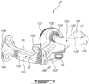
Fig. 4 is a three dimensional view illustrating components of the fuel system ofFig. 2 and an adaptor in accordance with one embodiment; -
Fig. 5 is a three dimensional view of the adaptor ofFig. 4 ; and -
Fig. 6 is a cross-sectional view of a transfer tube assembly in accordance with one embodiment. -
Fig. 1 illustrates an aircraft engine depicted as agas turbine engine 10 of a type preferably provided for use in subsonic flight. According to the illustrated example, thegas turbine engine 10 is a turboshaft engine generally comprising in serial flow communication acompressor section 12 for pressurizing the air, acombustor 16 in which the compressed air is mixed with fuel and ignited for generating an annular stream of hot combustion gases, and aturbine section 18 for extracting energy from the combustion gases. Thecompressor section 12 and theturbine section 18 are rotatable about acentral axis 11 of thegas turbine engine 10. In the embodiment shown, thegas turbine engine 10 comprises a high-pressure spool having a high-pressure shaft 20 drivingly engaging a high-pressure turbine 18A of theturbine section 18 to a high-pressure compressor 12A of thecompressor section 12, and a low-pressure spool having a low-pressure shaft 21 drivingly engaging a low-pressure turbine 18B of theturbine section 18 to a low-pressure compressor 12B of thecompressor section 12 and drivingly engaged to anoutput shaft 14. Theoutput shaft 14 may drivingly engage a rotor or any rotatable load. It will be understood that the contents of the present disclosure may be applicable to any suitable engines, such as turbofans, turboprops, turboshafts, and reciprocating engines, such as piston and rotary engines without departing from the scope of the present disclosure. - Referring now to
Fig. 2 , the gas turbine engine includes afuel system 100 including a fuel source 101 (e.g., reservoir) hydraulically connected aflow divider valve 102. Theflow divider valve 102 divides a fuel flow flowing from thefuel source 101 into a primary fuel flow F1 and a secondary fuel flow F2. Theflow divider valve 102 includes aninlet 102A receiving fuel from thefuel source 101, afirst outlet 102B outputting the primary fuel flow F1, and asecond outlet 102C outputting the secondary fuel flow F2. Theflow divider valve 102 may include a valve body movable within a valve housing to divide the fuel flow between the primary fuel flow F1 and the secondary fuel flow F2 at a specified ratio. Although not illustrated, it is understood that thefuel system 100 includes a fuel pump to drive the primary and secondary fuel flows F1, F2. - The
fuel system 100 includes amanifold 103 that distributes the fuel betweenfuel nozzles 104. Themanifold 103 may be a segmented ring extending circumferentially around thecentral axis 11. Themanifold 103 defines afirst manifold inlet 103A hydraulically connected to thefirst outlet 102B of theflow divider valve 102 and asecond manifold inlet 103B hydraulically connected to thesecond outlet 102C of theflow divider valve 102. Themanifold 103 includes aprimary fuel conduit 103C fluidly connected to thefirst manifold inlet 103A and leading tofirst manifold outlets 103D circumferentially distributed about thecentral axis 11, and includes asecondary fuel conduit 103E fluidly connected to thesecond manifold inlet 103B and leading tosecond manifold outlets 103F circumferentially distributed about thecentral axis 11. - As shown in
Figs. 2-3 , thefuel nozzles 104 each includes aprimary fuel passage 104A in fluid flow communication with a respective one of thefirst manifold outlets 103D and asecondary fuel passage 104B in fluid flow communication with a respective one of thesecond manifold outlets 103F. Thefuel nozzle 104 defines afirst nozzle outlet 104C in fluid communication with theprimary fuel passage 104A and asecond nozzle outlet 104D in fluid flow communication with thesecondary fuel passage 104B. These twofuel passages - Engine configurations used for multiple applications, such as turboshaft and turboprop, may reduce costs through economies of scale via the use of common hardware. Unique hardware is typically used when needed, to optimize weight and cost to meet the different application requirements. In some cases, common hardware has to interface with unique hardware. This may impose design constraints. For instance, the
fuel nozzles 104 may be a common hardware it that they may be used for more than one applications. However, theflow divider valve 102, which provides fuel for the manifold 103 is usually unique due to the different operability requirements. Rigid tubing and/or transfer tubes may be used to connect thefuel nozzles 104 to theflow divider valve 102. However, rigid tubing still physically couples the two mounting points together, which may result in a thermal mismatch during operation and may allow modes from one component to be transferred to the other. Transfer tubes decouple any thermal and dynamic modes from one component to the other, but they may not directly interface between common and unique hardware due to the inherent linear design constrain since they may have to be aligned parallel to thecentral axis 11 of thegas turbine engine 10. - Therefore, in the embodiment shown, an
adaptor 110 is provided. Theadaptor 110 is used to interconnect theflow divider valve 102 to themanifold 103. Theadaptor 110 is described below in more detail with reference toFigs. 4-5 . - Referring now to
Figs. 4-5 , in the embodiment shown, thefuel nozzles 104 are secured to acasing 19 of thegas turbine engine 10. Thecasing 19 defines a plurality ofapertures 19A circumferentially distributed about thecentral axis 11. Each of theapertures 19A is sized to accept a respective one of thefuel nozzles 104. As illustrated, thefirst outlet 102B and thesecond outlet 102C of theflow divider valve 102 face a direction having an axial component relative to thecentral axis 11. The direction faced by the first andsecond outlets flow divider valve 102 may be substantially axial. Similarly, thefirst manifold inlet 103A and thesecond manifold inlet 103B face the direction being substantially axial relative to thecentral axis 11. It may therefore be impractical to use transfer tubes to interconnect the manifold 103 to theflow divider valve 102 since, as mentioned above, the transfer tubes may require to be aligned parallel to thecentral axis 11. - The
adaptor 110 may allow the use of atransfer tube assembly 120 to interconnect the manifold 103 to theflow divider valve 102 while dynamically disconnecting these two components. This may avoid the transfer of thermal-induced stress or dynamic stress between these two components. In the embodiment shown, thetransfer tube assembly 120 is disposed between the manifold 103 and theadaptor 110. More detail about thistransfer tube assembly 120 are presented below with reference toFig. 6 . - The
adaptor 110 includes abody 111 slidably engageable by thetransfer tube assembly 120, afirst member 112 defining afirst fuel conduit 112A fluidly connected to thefirst manifold inlet 103A, and asecond member 113 defining asecond fuel conduit 113A fluidly connected to thesecond manifold inlet 103B. Thefirst fuel conduit 112A of thefirst member 112 fluidly connects thefirst outlet 102B of theflow divider valve 102 to thefirst manifold inlet 103A. Thesecond fuel conduit 113A of thesecond member 113 fluidly connects thesecond outlet 102C of theflow divider valve 102 to thesecond manifold inlet 103B. - In the present embodiment, the
first member 112 is monolithically connected to thebody 111. Stated differently, thebody 111 and thefirst member 112 may be part of a single monolithic body. Thesecond member 113 may be a tube, which may be substantially rigid, secured to thebody 111. The tube may be made of any suitable material, such as copper, steel, and so on. The tube may be welded or brazed to thebody 111. In some other embodiments, thesecond member 113 may be monolithically connected to thebody 111. - In the embodiment shown, the
first member 112 is a bracket that is secured to theflow divider valve 102. Therefore, thetransfer tube assembly 120 is supported by the bracket. In other words, thetransfer tube assembly 120 is supported by theflow divider valve 102 via the bracket. Thefirst member 112 therefore has a dual function: first, it provides fluid communication between the manifold 103 and theflow divider valve 102; second, it structurally supports thebody 111 and thetransfer tube assembly 120. - As shown in
Fig. 5 , thefirst member 112 has afirst section 112B extending from thebody 111 along a first direction D1 having a circumferential component and, in the present case, a radial component relative to thecentral axis 11, and asecond section 112C extending from thefirst section 112B along a second direction D2 having an axial component relative to thecentral axis 11. Thefirst section 112B is generally transverse to thesecond section 112C. Thesecond section 112C terminates at afirst end 112D. Afirst flange 112E is defined at thefirst end 112D. Thefirst flange 112E may be monolithic with thefirst member 112. Thefirst member 112 is secured to flowdivider valve 102 via thefirst flange 112E. Understandably, thefirst member 112 is secured to theflow divider valve 102 at a location where thefirst outlet 102B of theflow divider valve 102 registers with thefirst fuel conduit 112A of thefirst member 112 of theadaptor 110. - The
second member 113 defines a plurality ofstraight sections 113B interconnected with bends orelbows 113C such that thesecond member 113 extends from afirst tube end 113D at thebody 111 to asecond tube end 113E (Fig. 4 ) connected to asecond flange 113F. Thefirst tube end 113D is axially offset from thesecond tube end 113E. In the present embodiment, thefirst tube end 113D is also radially and circumferentially offset from thesecond tube end 113E. Other configurations are contemplated. Thesecond flange 113F may be welded or brazed to thesecond tube end 113E. Thesecond member 113 is secured to theflow divider valve 102 via thesecond flange 113F. Understandably, thesecond member 113 is secured to theflow divider valve 102 at a location where thesecond outlet 102C of theflow divider valve 102 registers with thesecond fuel conduit 113A of thesecond member 113 of theadaptor 110. As shown inFig. 4 , thefirst end 112D and thesecond tube end 113E of thefirst member 112 and of thesecond member 113 are spaced apart and distinct from one another. - Reference now to
Fig. 6 , the transfer tube assembly is described in more details. Thetransfer tube assembly 120 includes afirst transfer tube 121 having a rigid, tubular body extending along a longitudinal axis A from a first tube end 121A to asecond tube end 121B. Thefirst tube end 121A is slidably received within afirst connection port 111A of thebody 111, whereas thesecond tube end 121B extends to outside thefirst connection port 111A so as to be slidably receivable by a firstmanifold port 103G of themanifold 103. The firstmanifold port 103G is connected to thefirst manifold inlet 103A. Around either ends 121A, 121B of thefirst transfer tube 121, O-rings 124 may be mounted for sealing engagement with the corresponding ports, thereby sealing a passage from one port to the other via thefirst transfer tube 121. Asecond transfer tube 122 of thetransfer tube assembly 120 has a rigid, tubular body extending along a longitudinal axis A' from a first tube end 122A to a second tube end 122B. Thefirst tube end 122A is slidably received by asecond connection port 111B of thebody 111, whereas the second tube end 122B extends to outside thesecond connection port 111B so as to be slidably receivable by a secondmanifold port 103H of themanifold 103. The secondmanifold port 103H is connected to thesecond manifold inlet 103B. Around either ends 122A, 122B of thesecond transfer tube 122, O-rings 124 may be mounted for sealing engagement with the corresponding ports, thereby sealing a passage from one port to the other via thesecond transfer tube 122. - According to some embodiments, the
transfer tube assembly 120 includes adrain sleeve 123 extending around thefirst transfer tube 121 and thesecond transfer tube 122. As shown inFig. 6 , O-rings 124 may be mounted around thebody 111 and around themanifold 103 for sealing engagement with an inner cylindrical surface of thedrain sleeve 123, thereby defining extremities of a sealedcavity 125 inside thedrain sleeve 123. However, thedrain sleeve 123 may be omitted depending on the implementation. In the embodiment shown, a sealedcavity 125 is fluidly connected to a drain nipple 114 (Fig. 5 ). Thedrain nipple 114 may be a monolithic part of thebody 111. Thedrain nipple 114 may extend downwardly and may be fluidly connected to a hose or any suitable conduits for scavenging fuel that leaked from thetransfer tube assembly 120. This hose may be connected to thefuel source 101 so that leaked fuel may be flown away from thefuel nozzles 104. This fuel may then be flown either overboard or back to the fuel source. - The
adaptor 110 may be manufactured through any method of manufacturing such as additive manufacturing, metal injection molding, conventional. It may allow the unique hardware's interfaces (e.g., flow divider valve 102) to be adapted and accept the interface used by the common hardware (e.g., fuel nozzles 104). Theadaptor 110 and transfertube assembly 120 may accommodate assembly deflections between the ports and may ensure thefuel nozzles 104 are decoupled from any modes or thermal loads from theflow divider valve 102. - This disclosed configuration may offer advantages such as a lower number individual components to dynamically and thermally decouple the interface between the
fuel nozzles 104 and theflow divider valve 102 while allowing fluid communication between the two and accommodating assembly deflections between the different ports of theflow divider valve 102. This may result in a configuration having a reduced weight compared to conventional configuration. This configuration may also reduce manufacturing and assembly costs. - The embodiments described in this document provide non-limiting examples of possible implementations of the present technology. Upon review of the present disclosure, a person of ordinary skill in the art will recognize that changes may be made to the embodiments described herein without departing from the scope of the present technology. Yet further modifications could be implemented by a person of ordinary skill in the art in view of the present disclosure, which modifications would be within the scope of the present technology.
Claims (10)
- A fuel system (100) of an aircraft engine (10), comprising:a fuel manifold (103) having a first manifold inlet (103A) and a second manifold inlet (103B);a transfer tube assembly (120) having a first tube (121) slidably engaged to the fuel manifold (103) and fluidly connected to the first manifold inlet (103A), and a second tube (122) slidably engaged to the fuel manifold (103) and fluidly connected to the second manifold inlet (103B); andan adaptor (110) having:a body (111) slidably engaged by the first tube (121) and by the second tube (122),a first member (112) defining a first fuel conduit (112A) fluidly connected to the first manifold inlet (103A) via the first tube (121), anda second member (113) defining a second fuel conduit (113A) fluidly connected to the second manifold inlet (103B) via the second tube (122).
- The fuel system (100) of claim 1, wherein the first member (112) is monolithically connected to the body (111).
- The fuel system (100) of claim 1 or 2, wherein the second member (113) is a tube secured to the body (111).
- The fuel system (100) of any preceding claim, wherein the first member (112) extends from the body (111) to a first end (112D), the first end (112D) defining a first flange (112E) securable to a flow divider valve (102).
- The fuel system (100) of claim 4, wherein the second member (113) extends from the body (111) to a second end (113E), the second end (113E) defining a second flange (113F) securable to the flow divider valve (102).
- The fuel system (100) of any preceding claim, wherein the first member (112) and the second member (113) extend from the body (111) and end respectively at a first end (112D) and a second end (113E), the first end (112D) spaced apart and distinct from the second end (112E).
- The fuel system (100) of any preceding claim, comprising a flow divider valve (102) having an inlet (102A), a primary outlet (102B) hydraulically connected to the first fuel conduit (112A), and a secondary outlet (102C) hydraulically connected to the second fuel conduit (113A).
- The fuel system (100) of claim 7, wherein the first member (112) is a bracket secured to the flow divider valve (102), the transfer tube assembly (120) supported by the bracket secured to the flow divider valve (102).
- The fuel system (100) of any preceding claim, wherein the adaptor (110) further comprises:a first connection port (111A) and a second connection port (111B) defined by the body (111),the first member (112) defining the first fuel conduit (112A) being in fluid communication with the first connection port (111A), andthe second member (113) defining the second fuel conduit (113A) being in fluid communication with the second connection port (111B).
- An aircraft engine (10) comprising the fuel system (100) of any preceding claim.
Applications Claiming Priority (1)
| Application Number | Priority Date | Filing Date | Title |
|---|---|---|---|
| US17/810,624 US12241416B2 (en) | 2022-07-04 | 2022-07-04 | Adaptor for a fuel system of an aircraft engine |
Publications (1)
| Publication Number | Publication Date |
|---|---|
| EP4303420A1 true EP4303420A1 (en) | 2024-01-10 |
Family
ID=87074630
Family Applications (1)
| Application Number | Title | Priority Date | Filing Date |
|---|---|---|---|
| EP23183136.3A Pending EP4303420A1 (en) | 2022-07-04 | 2023-07-03 | Adaptor for a fuel system of an aircraft engine |
Country Status (3)
| Country | Link |
|---|---|
| US (1) | US12241416B2 (en) |
| EP (1) | EP4303420A1 (en) |
| CA (1) | CA3204216A1 (en) |
Citations (3)
| Publication number | Priority date | Publication date | Assignee | Title |
|---|---|---|---|---|
| US4467610A (en) * | 1981-04-17 | 1984-08-28 | General Electric Company | Gas turbine fuel system |
| US5031407A (en) * | 1989-06-06 | 1991-07-16 | Allied-Signal Inc. | Apparatus for use in a fuel delivery system for a gas turbine engine |
| US20150176496A1 (en) * | 2012-08-06 | 2015-06-25 | Turbomeca | Dual-circuit modular injection tube |
Family Cites Families (14)
| Publication number | Priority date | Publication date | Assignee | Title |
|---|---|---|---|---|
| US5273249A (en) | 1992-11-12 | 1993-12-28 | General Electric Company | Slide joint bracket |
| US7516736B2 (en) * | 2005-05-17 | 2009-04-14 | Honeywell International Inc. | Fuel distributor and mounting system therefor and method of mounting a fuel distributor |
| US9631560B2 (en) * | 2011-11-22 | 2017-04-25 | United Technologies Corporation | Fuel-air mixture distribution for gas turbine engine combustors |
| WO2015031823A1 (en) * | 2013-08-30 | 2015-03-05 | United Technologies Corporation | Fuel manifold for a gas turbine engine |
| US9797313B2 (en) * | 2014-01-16 | 2017-10-24 | Pratt & Whitney Canada Corp. | Internal manifold with fuel inlet |
| US9874351B2 (en) | 2015-04-14 | 2018-01-23 | General Electric Company | Thermally-coupled fuel manifold |
| US20180087776A1 (en) | 2016-09-23 | 2018-03-29 | General Electric Company | Mounting assembly for gas turbine engine fluid conduit |
| US20190107285A1 (en) * | 2017-10-06 | 2019-04-11 | Pratt & Whitney Canada Corp. | Segmented fuel distributor |
| US11060731B2 (en) * | 2018-10-02 | 2021-07-13 | Pratt & Whitney Canada Corp. | Fuel manifold assembly |
| GB201820505D0 (en) | 2018-12-17 | 2019-01-30 | Rolls Royce | Connector system |
| US11719159B2 (en) | 2021-05-03 | 2023-08-08 | Pratt & Whitney Canada Corp. | Transfer tube assembly |
| US11867125B2 (en) * | 2021-06-30 | 2024-01-09 | Pratt & Whitney Canada Corp. | Fuel manifold adapter |
| US20230018918A1 (en) * | 2021-07-19 | 2023-01-19 | Pratt & Whitney Canada Corp. | Manifold purge for gaseous fuel system of engine |
| US11939922B2 (en) | 2022-08-19 | 2024-03-26 | Pratt & Whitney Canada Corp. | Fuel assembly for a gas turbine engine |
-
2022
- 2022-07-04 US US17/810,624 patent/US12241416B2/en active Active
-
2023
- 2023-06-20 CA CA3204216A patent/CA3204216A1/en active Pending
- 2023-07-03 EP EP23183136.3A patent/EP4303420A1/en active Pending
Patent Citations (3)
| Publication number | Priority date | Publication date | Assignee | Title |
|---|---|---|---|---|
| US4467610A (en) * | 1981-04-17 | 1984-08-28 | General Electric Company | Gas turbine fuel system |
| US5031407A (en) * | 1989-06-06 | 1991-07-16 | Allied-Signal Inc. | Apparatus for use in a fuel delivery system for a gas turbine engine |
| US20150176496A1 (en) * | 2012-08-06 | 2015-06-25 | Turbomeca | Dual-circuit modular injection tube |
Also Published As
| Publication number | Publication date |
|---|---|
| US12241416B2 (en) | 2025-03-04 |
| CA3204216A1 (en) | 2024-01-04 |
| US20240003298A1 (en) | 2024-01-04 |
Similar Documents
| Publication | Publication Date | Title |
|---|---|---|
| CN109415945B (en) | Modular annular heat exchanger | |
| CA2638541C (en) | Fuel inlet with crescent shaped passage for gas turbine engines | |
| EP3081783B1 (en) | Thermally-coupled fuel manifold | |
| EP3730743B1 (en) | Multiwall tube and fitting for bearing oil supply | |
| US11092084B2 (en) | Fuel delivery system for a gas turbine engine | |
| CA2770858C (en) | Fuel manifold with jumper tubes | |
| US10753230B2 (en) | Gas turbine engine cooling air manifolds with spoolies | |
| EP3597869B1 (en) | Sealing configuration for a transfer tube assembly to reduce air leakage | |
| US11466590B1 (en) | Mid-turbine frame with intermediary plenum | |
| US20220307694A1 (en) | Modular injector bolt for an engine | |
| EP3039268A1 (en) | Fuel manifold for a gas turbine engine | |
| US12241416B2 (en) | Adaptor for a fuel system of an aircraft engine | |
| US12297776B2 (en) | Fuel manifold adapter | |
| JP2006329425A (en) | Expansion joint and method of assembling it | |
| US10927764B2 (en) | Fuel manifold assembly | |
| US11885242B2 (en) | Diffuser ring with air manifold | |
| US12617541B1 (en) | Exhaust case for aircraft engine | |
| EP3597868A1 (en) | Sealing configuration using a boot seal to reduce air leakage |
Legal Events
| Date | Code | Title | Description |
|---|---|---|---|
| PUAI | Public reference made under article 153(3) epc to a published international application that has entered the european phase |
Free format text: ORIGINAL CODE: 0009012 |
|
| STAA | Information on the status of an ep patent application or granted ep patent |
Free format text: STATUS: THE APPLICATION HAS BEEN PUBLISHED |
|
| AK | Designated contracting states |
Kind code of ref document: A1 Designated state(s): AL AT BE BG CH CY CZ DE DK EE ES FI FR GB GR HR HU IE IS IT LI LT LU LV MC ME MK MT NL NO PL PT RO RS SE SI SK SM TR |
|
| STAA | Information on the status of an ep patent application or granted ep patent |
Free format text: STATUS: REQUEST FOR EXAMINATION WAS MADE |
|
| 17P | Request for examination filed |
Effective date: 20240710 |
|
| RBV | Designated contracting states (corrected) |
Designated state(s): AL AT BE BG CH CY CZ DE DK EE ES FI FR GB GR HR HU IE IS IT LI LT LU LV MC ME MK MT NL NO PL PT RO RS SE SI SK SM TR |
|
| GRAJ | Information related to disapproval of communication of intention to grant by the applicant or resumption of examination proceedings by the epo deleted |
Free format text: ORIGINAL CODE: EPIDOSDIGR1 |
|
| GRAP | Despatch of communication of intention to grant a patent |
Free format text: ORIGINAL CODE: EPIDOSNIGR1 |
|
| GRAP | Despatch of communication of intention to grant a patent |
Free format text: ORIGINAL CODE: EPIDOSNIGR1 |
|
| STAA | Information on the status of an ep patent application or granted ep patent |
Free format text: STATUS: GRANT OF PATENT IS INTENDED |
|
| INTG | Intention to grant announced |
Effective date: 20260119 |