EP4303414A1 - Contrail suppression system - Google Patents
Contrail suppression system Download PDFInfo
- Publication number
- EP4303414A1 EP4303414A1 EP23182903.7A EP23182903A EP4303414A1 EP 4303414 A1 EP4303414 A1 EP 4303414A1 EP 23182903 A EP23182903 A EP 23182903A EP 4303414 A1 EP4303414 A1 EP 4303414A1
- Authority
- EP
- European Patent Office
- Prior art keywords
- tube bundle
- exhaust gas
- outlet
- turbine engine
- inlet
- Prior art date
- Legal status (The legal status is an assumption and is not a legal conclusion. Google has not performed a legal analysis and makes no representation as to the accuracy of the status listed.)
- Granted
Links
Images


Classifications
-
- F—MECHANICAL ENGINEERING; LIGHTING; HEATING; WEAPONS; BLASTING
- F02—COMBUSTION ENGINES; HOT-GAS OR COMBUSTION-PRODUCT ENGINE PLANTS
- F02C—GAS-TURBINE PLANTS; AIR INTAKES FOR JET-PROPULSION PLANTS; CONTROLLING FUEL SUPPLY IN AIR-BREATHING JET-PROPULSION PLANTS
- F02C7/00—Features, components parts, details or accessories, not provided for in, or of interest apart form groups F02C1/00 - F02C6/00; Air intakes for jet-propulsion plants
- F02C7/12—Cooling of plants
-
- F—MECHANICAL ENGINEERING; LIGHTING; HEATING; WEAPONS; BLASTING
- F02—COMBUSTION ENGINES; HOT-GAS OR COMBUSTION-PRODUCT ENGINE PLANTS
- F02C—GAS-TURBINE PLANTS; AIR INTAKES FOR JET-PROPULSION PLANTS; CONTROLLING FUEL SUPPLY IN AIR-BREATHING JET-PROPULSION PLANTS
- F02C3/00—Gas-turbine plants characterised by the use of combustion products as the working fluid
- F02C3/20—Gas-turbine plants characterised by the use of combustion products as the working fluid using a special fuel, oxidant, or dilution fluid to generate the combustion products
- F02C3/22—Gas-turbine plants characterised by the use of combustion products as the working fluid using a special fuel, oxidant, or dilution fluid to generate the combustion products the fuel or oxidant being gaseous at standard temperature and pressure
-
- F—MECHANICAL ENGINEERING; LIGHTING; HEATING; WEAPONS; BLASTING
- F02—COMBUSTION ENGINES; HOT-GAS OR COMBUSTION-PRODUCT ENGINE PLANTS
- F02C—GAS-TURBINE PLANTS; AIR INTAKES FOR JET-PROPULSION PLANTS; CONTROLLING FUEL SUPPLY IN AIR-BREATHING JET-PROPULSION PLANTS
- F02C9/00—Controlling gas-turbine plants; Controlling fuel supply in air- breathing jet-propulsion plants
- F02C9/16—Control of working fluid flow
- F02C9/18—Control of working fluid flow by bleeding, bypassing or acting on variable working fluid interconnections between turbines or compressors or their stages
-
- B—PERFORMING OPERATIONS; TRANSPORTING
- B64—AIRCRAFT; AVIATION; COSMONAUTICS
- B64D—EQUIPMENT FOR FITTING IN OR TO AIRCRAFT; FLIGHT SUITS; PARACHUTES; ARRANGEMENT OR MOUNTING OF POWER PLANTS OR PROPULSION TRANSMISSIONS IN AIRCRAFT
- B64D33/00—Arrangement in aircraft of power plant parts or auxiliaries not otherwise provided for
- B64D33/04—Arrangement in aircraft of power plant parts or auxiliaries not otherwise provided for of exhaust outlets or jet pipes
-
- F—MECHANICAL ENGINEERING; LIGHTING; HEATING; WEAPONS; BLASTING
- F01—MACHINES OR ENGINES IN GENERAL; ENGINE PLANTS IN GENERAL; STEAM ENGINES
- F01D—NON-POSITIVE DISPLACEMENT MACHINES OR ENGINES, e.g. STEAM TURBINES
- F01D25/00—Component parts, details, or accessories, not provided for in, or of interest apart from, other groups
- F01D25/32—Collecting of condensation water; Drainage ; Removing solid particles
-
- F—MECHANICAL ENGINEERING; LIGHTING; HEATING; WEAPONS; BLASTING
- F02—COMBUSTION ENGINES; HOT-GAS OR COMBUSTION-PRODUCT ENGINE PLANTS
- F02C—GAS-TURBINE PLANTS; AIR INTAKES FOR JET-PROPULSION PLANTS; CONTROLLING FUEL SUPPLY IN AIR-BREATHING JET-PROPULSION PLANTS
- F02C3/00—Gas-turbine plants characterised by the use of combustion products as the working fluid
- F02C3/20—Gas-turbine plants characterised by the use of combustion products as the working fluid using a special fuel, oxidant, or dilution fluid to generate the combustion products
- F02C3/30—Adding water, steam or other fluids for influencing combustion, e.g. to obtain cleaner exhaust gases
-
- F—MECHANICAL ENGINEERING; LIGHTING; HEATING; WEAPONS; BLASTING
- F02—COMBUSTION ENGINES; HOT-GAS OR COMBUSTION-PRODUCT ENGINE PLANTS
- F02C—GAS-TURBINE PLANTS; AIR INTAKES FOR JET-PROPULSION PLANTS; CONTROLLING FUEL SUPPLY IN AIR-BREATHING JET-PROPULSION PLANTS
- F02C7/00—Features, components parts, details or accessories, not provided for in, or of interest apart form groups F02C1/00 - F02C6/00; Air intakes for jet-propulsion plants
-
- F—MECHANICAL ENGINEERING; LIGHTING; HEATING; WEAPONS; BLASTING
- F02—COMBUSTION ENGINES; HOT-GAS OR COMBUSTION-PRODUCT ENGINE PLANTS
- F02C—GAS-TURBINE PLANTS; AIR INTAKES FOR JET-PROPULSION PLANTS; CONTROLLING FUEL SUPPLY IN AIR-BREATHING JET-PROPULSION PLANTS
- F02C7/00—Features, components parts, details or accessories, not provided for in, or of interest apart form groups F02C1/00 - F02C6/00; Air intakes for jet-propulsion plants
- F02C7/12—Cooling of plants
- F02C7/14—Cooling of plants of fluids in the plant, e.g. lubricant or fuel
- F02C7/141—Cooling of plants of fluids in the plant, e.g. lubricant or fuel of working fluid
-
- F—MECHANICAL ENGINEERING; LIGHTING; HEATING; WEAPONS; BLASTING
- F02—COMBUSTION ENGINES; HOT-GAS OR COMBUSTION-PRODUCT ENGINE PLANTS
- F02K—JET-PROPULSION PLANTS
- F02K1/00—Plants characterised by the form or arrangement of the jet pipe or nozzle; Jet pipes or nozzles peculiar thereto
- F02K1/78—Other construction of jet pipes
- F02K1/82—Jet pipe walls, e.g. liners
- F02K1/822—Heat insulating structures or liners, cooling arrangements, e.g. post combustion liners; Infrared radiation suppressors
-
- F—MECHANICAL ENGINEERING; LIGHTING; HEATING; WEAPONS; BLASTING
- F02—COMBUSTION ENGINES; HOT-GAS OR COMBUSTION-PRODUCT ENGINE PLANTS
- F02C—GAS-TURBINE PLANTS; AIR INTAKES FOR JET-PROPULSION PLANTS; CONTROLLING FUEL SUPPLY IN AIR-BREATHING JET-PROPULSION PLANTS
- F02C7/00—Features, components parts, details or accessories, not provided for in, or of interest apart form groups F02C1/00 - F02C6/00; Air intakes for jet-propulsion plants
- F02C7/08—Heating air supply before combustion, e.g. by exhaust gases
-
- F—MECHANICAL ENGINEERING; LIGHTING; HEATING; WEAPONS; BLASTING
- F02—COMBUSTION ENGINES; HOT-GAS OR COMBUSTION-PRODUCT ENGINE PLANTS
- F02C—GAS-TURBINE PLANTS; AIR INTAKES FOR JET-PROPULSION PLANTS; CONTROLLING FUEL SUPPLY IN AIR-BREATHING JET-PROPULSION PLANTS
- F02C7/00—Features, components parts, details or accessories, not provided for in, or of interest apart form groups F02C1/00 - F02C6/00; Air intakes for jet-propulsion plants
- F02C7/12—Cooling of plants
- F02C7/14—Cooling of plants of fluids in the plant, e.g. lubricant or fuel
- F02C7/141—Cooling of plants of fluids in the plant, e.g. lubricant or fuel of working fluid
- F02C7/143—Cooling of plants of fluids in the plant, e.g. lubricant or fuel of working fluid before or between the compressor stages
- F02C7/1435—Cooling of plants of fluids in the plant, e.g. lubricant or fuel of working fluid before or between the compressor stages by water injection
-
- F—MECHANICAL ENGINEERING; LIGHTING; HEATING; WEAPONS; BLASTING
- F02—COMBUSTION ENGINES; HOT-GAS OR COMBUSTION-PRODUCT ENGINE PLANTS
- F02C—GAS-TURBINE PLANTS; AIR INTAKES FOR JET-PROPULSION PLANTS; CONTROLLING FUEL SUPPLY IN AIR-BREATHING JET-PROPULSION PLANTS
- F02C7/00—Features, components parts, details or accessories, not provided for in, or of interest apart form groups F02C1/00 - F02C6/00; Air intakes for jet-propulsion plants
- F02C7/12—Cooling of plants
- F02C7/16—Cooling of plants characterised by cooling medium
-
- F—MECHANICAL ENGINEERING; LIGHTING; HEATING; WEAPONS; BLASTING
- F05—INDEXING SCHEMES RELATING TO ENGINES OR PUMPS IN VARIOUS SUBCLASSES OF CLASSES F01-F04
- F05D—INDEXING SCHEME FOR ASPECTS RELATING TO NON-POSITIVE-DISPLACEMENT MACHINES OR ENGINES, GAS-TURBINES OR JET-PROPULSION PLANTS
- F05D2220/00—Application
- F05D2220/30—Application in turbines
- F05D2220/32—Application in turbines in gas turbines
- F05D2220/323—Application in turbines in gas turbines for aircraft propulsion, e.g. jet engines
-
- F—MECHANICAL ENGINEERING; LIGHTING; HEATING; WEAPONS; BLASTING
- F05—INDEXING SCHEMES RELATING TO ENGINES OR PUMPS IN VARIOUS SUBCLASSES OF CLASSES F01-F04
- F05D—INDEXING SCHEME FOR ASPECTS RELATING TO NON-POSITIVE-DISPLACEMENT MACHINES OR ENGINES, GAS-TURBINES OR JET-PROPULSION PLANTS
- F05D2260/00—Function
- F05D2260/20—Heat transfer, e.g. cooling
- F05D2260/213—Heat transfer, e.g. cooling by the provision of a heat exchanger within the cooling circuit
-
- F—MECHANICAL ENGINEERING; LIGHTING; HEATING; WEAPONS; BLASTING
- F05—INDEXING SCHEMES RELATING TO ENGINES OR PUMPS IN VARIOUS SUBCLASSES OF CLASSES F01-F04
- F05D—INDEXING SCHEME FOR ASPECTS RELATING TO NON-POSITIVE-DISPLACEMENT MACHINES OR ENGINES, GAS-TURBINES OR JET-PROPULSION PLANTS
- F05D2260/00—Function
- F05D2260/60—Fluid transfer
- F05D2260/602—Drainage
-
- F—MECHANICAL ENGINEERING; LIGHTING; HEATING; WEAPONS; BLASTING
- F05—INDEXING SCHEMES RELATING TO ENGINES OR PUMPS IN VARIOUS SUBCLASSES OF CLASSES F01-F04
- F05D—INDEXING SCHEME FOR ASPECTS RELATING TO NON-POSITIVE-DISPLACEMENT MACHINES OR ENGINES, GAS-TURBINES OR JET-PROPULSION PLANTS
- F05D2270/00—Control
- F05D2270/01—Purpose of the control system
- F05D2270/08—Purpose of the control system to produce clean exhaust gases
- F05D2270/081—Purpose of the control system to produce clean exhaust gases with as little smoke as possible
Definitions
- the present disclosure relates to a gas turbine engine and more particularly, to exhaust suppression in a gas turbine engine.
- Gas turbine engines such as turbofan engines, may be used for aircraft propulsion.
- Condensation trails are typically formed when water molecules present in the exhaust gas from a turbofan engine becomes supersaturated after mixing with ambient air. These water molecules condense and quickly freeze into ice particles/crystals.
- upstream refers to the relative direction with respect to fluid flow in a fluid pathway.
- upstream refers to the direction from which the fluid flows
- downstream refers to the direction to which the fluid flows.
- turbomachine or “turbomachinery” refers to a machine including one or more compressors, a heat generating section (e.g., a combustion section), and one or more turbines that together generate a torque output.
- gas turbine engine refers to an engine having a turbomachine as all or a portion of its power source.
- Example gas turbine engines include turbofan engines, turboprop engines, turbojet engines, turboshaft engines, etc., as well as hybrid-electric versions of one or more of these engines.
- the present disclosure is generally related to a contrail suppression system for a gas turbine engine.
- the formation of condensation trails (contrails) from gas turbine engine exhausts are suspected to have negative impact on climate conditions. Contrails are typically formed when water molecules present in exhaust gas becomes supersaturated after mixing with ambient air. These water molecules then condense and quickly freeze into ice particles/crystals. Contrails are known to form cirrus clouds and could sometimes persist for hours over several miles. Contrail formation is expected to be even more severe in hydrogen-fueled aircraft as compared to fossil-fueled aircraft since hydrogen combustion can release over 7 times more water.
- This disclosure provides a contrail suppression system which incorporates a three-fluid shell and tube device such as a heat exchanger to suppress contrails from aircraft gas turbine engines, while minimizing exhaust gas pressure drop, thereby reducing any impact on overall engine thrust.
- the three-fluid heat exchanger works in suppressing contrails by first cooling the exhaust gas in a waste heat recovery (WHR) section and then dehumidifying the exhaust gas in a condenser section of the heat exchanger.
- WHR waste heat recovery
- the heat recovered in the WHR section is used to preheat compressed air from a low-pressure compressor to increase fuel efficiency while condensate water extracted from the condenser section of the heat exchanger may be injected either into the combustion chamber to help with nitrogen oxide (NOx) reduction, into a high-pressure turbine of the gas turbine engine for turbine blade cooling or may be stored in a storage tank or vessel aboard the aircraft or on the gas turbine engine.
- NOx nitrogen oxide
- the heat exchanger for the contrail suppression system may be without the WHR section. It would only have the condenser section for dehumidifying the exhaust gas, which would eliminate the benefit of increased fuel efficiency and may result in lower effectiveness of contrail suppression.
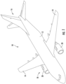
- FIG. 1 is a perspective view of an exemplary aircraft 10 that may incorporate at least one exemplary embodiment of the present disclosure.
- the aircraft 10 has a fuselage 12, wings 14 attached to the fuselage 12, and an empennage 16.
- the aircraft 10 further includes a propulsion system 18 that produces a propulsive thrust to propel the aircraft 10 in flight, during taxiing operations, etc.
- the propulsion system 18 is shown attached to the wing(s) 14, in other embodiments it may additionally or alternatively include one or more aspects coupled to other parts of the aircraft 10, such as, for example, the empennage 16, the fuselage 12, or both.
- the propulsion system 18 includes at least one engine.
- the aircraft 10 includes a pair of gas turbine engines 20.
- Each gas turbine engine 20 is mounted to the aircraft 10 in an under-wing configuration. Each gas turbine engine 20 is capable of selectively generating a propulsive thrust for the aircraft 10.
- the gas turbine engines 20 may be configured to burn various forms of fuel including, but not limited to unless otherwise provided, jet fuel/aviation turbine fuel, and hydrogen fuel.
- FIG. 2 is a cross-sectional side view of a gas turbine engine 20 in accordance with an exemplary embodiment of the present disclosure. More particularly, for the embodiment of FIG. 2 , the gas turbine engine 20 is a multi-spool, high-bypass turbofan jet engine, sometimes also referred to as a "turbofan engine.” As shown in FIG. 2 , the gas turbine engine 20 defines an axial direction A (extending parallel to a longitudinal centerline 22 provided for reference), a radial direction R, and a circumferential direction C extending about the longitudinal centerline 22. In general, the gas turbine engine 20 includes a fan section 24 and a turbomachine 26 disposed downstream from the fan section 24.
- the exemplary turbomachine 26 depicted generally includes an engine casing 28 that defines an annular core inlet 30.
- the engine casing 28 at least partially encases, in serial flow relationship, a compressor section including a booster or low-pressure (LP) compressor 32 and a high-pressure (HP) compressor 34, a combustion section 36, a turbine section including a high-pressure (HP) turbine 38 and a low-pressure (LP) turbine 40, and a jet exhaust nozzle 42.
- LP booster or low-pressure
- HP high-pressure
- HP high-pressure
- LP low-pressure
- a high-pressure (HP) shaft 44 drivingly connects the (HP) turbine 38 to the (HP) compressor 34.
- a low-pressure (LP) shaft 46 that drivingly connects the (LP) turbine 40 to the (LP) compressor 32.
- the compressor section, combustion section 36, turbine section, and jet exhaust nozzle 42 together define a working gas flow path 48 through the gas turbine engine 20.
- the fan section 24 includes a fan 50 having a plurality of fan blades 52 coupled to a disk 54 in a spaced apart manner. As depicted, the fan blades 52 extend outwardly from disk 54 generally along the radial direction R. Each fan blade 52 is rotatable with the disk 54 about a pitch axis P by virtue of the fan blades 52 being operatively coupled to a suitable pitch change mechanism 56 configured to collectively vary the pitch of the fan blades 52, e.g., in unison.
- the gas turbine engine 20 further includes a power gear box 58.
- the fan blades 52, disk 54, and pitch change mechanism 56 are together rotatable about the longitudinal centerline 22 by the (LP) shaft 46 across the power gear box 58.
- the power gear box 58 includes a plurality of gears for adjusting a rotational speed of the fan 50 relative to a rotational speed of the (LP) shaft 46, such that the fan 50 and the (LP) shaft 46 may rotate at more efficient relative speeds.
- the disk 54 is covered by rotatable front hub 60 of the fan section 24 (sometimes also referred to as a "spinner").
- the front hub 60 is aerodynamically contoured to promote an airflow through the plurality of fan blades 52.
- the exemplary fan section 24 includes an annular fan casing or outer nacelle 62 that circumferentially surrounds the fan 50 and/or at least a portion of the turbomachine 26.
- the nacelle 62 is supported relative to the turbomachine 26 by a plurality of circumferentially spaced struts or outlet guide vanes 64 in the embodiment depicted.
- a downstream section 66 of the nacelle 62 extends over an outer portion of the turbomachine 26 to define a bypass airflow passage 68 therebetween.
- the exemplary gas turbine engine 20 depicted in FIG. 2 is provided by way of example only, and that in other exemplary embodiments, the gas turbine engine 20 may have other configurations.
- the gas turbine engine 20 depicted is configured as a ducted gas turbine engine (i.e., including the outer nacelle 62), in other embodiments, the gas turbine engine 20 may be an unducted or non-ducted gas turbine engine (such that the fan 50 is an unducted fan, and the outlet guide vanes 64 are cantilevered from the engine casing 28).
- the gas turbine engine 20 depicted is configured as a geared gas turbine engine (i.e., including the power gear box 58) and a variable pitch gas turbine engine (i.e., including a fan 50 configured as a variable pitch fan), in other embodiments, the gas turbine engine 20 may be configured as a direct drive gas turbine engine (such that the (LP) shaft 46 rotates at the same speed as the fan 50), as a fixed pitch gas turbine engine (such that the fan 50 includes fan blades 52 that are not rotatable about a pitch axis P), or both. It should also be appreciated, that in still other exemplary embodiments, aspects of the present disclosure may be incorporated into any other suitable gas turbine engine. For example, in other exemplary embodiments, aspects of the present disclosure may (as appropriate) be incorporated into, e.g., a turboprop gas turbine engine, a turboshaft gas turbine engine, or a turbojet gas turbine engine.
- a volume of air 70 enters the gas turbine engine 20 through an associated inlet 72 of the nacelle 62 and fan section 24.
- a first portion of air 74 is directed or routed into the bypass airflow passage 68 and a second portion of air 76 is directed or routed into the working gas flow path 48, or more specifically into the (LP) compressor 32.
- the ratio between the first portion of air 74 and the second portion of air 76 is commonly known as a bypass ratio.
- Pressure of the second portion of air 76 is then increased as it is routed through the (HP) compressor 34 and into the combustion section 36, where it is mixed with fuel and burned to provide combustion gases 78.
- the combustion gases 78 are routed through the (HP) turbine 38 where a portion of thermal and/or kinetic energy from the combustion gases 78 is extracted via sequential stages of (HP) turbine stator vanes 80 that are coupled to a turbine casing and (HP) turbine rotor blades 82 that are coupled to the (HP) shaft 44, thus causing the (HP) shaft 44 to rotate, thereby supporting operation of the (HP) compressor 34.
- the combustion gases 78 are then routed through the (LP) turbine 40 where a second portion of thermal and kinetic energy is extracted from the combustion gases 78 via sequential stages of (LP) turbine stator vanes 84 that are coupled to a turbine casing and (LP) turbine rotor blades 86 that are coupled to the (LP) shaft 46, thus causing the (LP) shaft 46 to rotate, thereby supporting operation of the (LP) compressor 32 and/or rotation of the fan 50.
- the combustion gases 78 are subsequently routed through the jet exhaust nozzle 42 of the turbomachine 26 to provide propulsive thrust. Simultaneously, the pressure of the first portion of air 74 is substantially increased as it is routed through the bypass airflow passage 68 before it is exhausted from a fan nozzle exhaust section 88 of the gas turbine engine 20, also providing propulsive thrust.
- the (HP) turbine 38, the (LP) turbine 40, and the fan nozzle exhaust section 88 at least partially define a hot gas path 90 for routing the combustion gases 78 through the turbomachine 26.
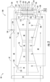
- FIG. 3 is a schematic view of a portion of an exemplary gas turbine engine 20 shown in FIG. 2 .
- FIG. 3 depicts, in serial flow order, the fan section 24, the (LP) compressor 32, the (HP) compressor 34, the combustion section 36, the (HP) turbine 38 and the (LP) turbine 40.
- FIG. 3 further depicts the nacelle 62 including the bypass airflow passage 68 and the jet exhaust nozzle 42.
- the gas turbine engine 20 includes a contrail reduction or suppression system 100 herein denoted as system 100.
- the system 100 includes at least one heat exchanger 102 in fluid communication with the jet exhaust nozzle 42.
- FIG. 4 provides and forward-looking view of an aft end of the jet exhaust nozzle 42 according to various embodiments of the present disclosure.
- the heat exchanger(s) 102 may be disposed inside the jet exhaust nozzle 42 at various locations.
- the heat exchanger 102 may be positioned inside of the jet exhaust nozzle 42 or along an inner wall 92 of the jet exhaust nozzle 42.
- the heat exchangers 102 may be circumferentially spaced along the inner wall 92.
- the heat exchanger 102 or one or more heat exchangers 102 may be positioned outside of the inner wall 92 of the jet exhaust nozzle 42.
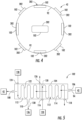
- FIG. 5 provides a schematic view of an exemplary heat exchanger 102 according to various embodiments of the present disclosure.
- the heat exchanger 102 includes a shell 104 having an exhaust gas inlet 106, an exhaust gas outlet 108, a condensate drain 110.
- the heat exchanger 102 further includes a flow chamber 112 defined within the shell 104 and in fluid communication with the exhaust gas inlet 106, the exhaust gas outlet 108 and the condensate drain 110.
- the exhaust gas inlet 106 and the exhaust gas outlet 108 are in fluid communication with the jet exhaust nozzle 42.
- the heat exchanger 102 further includes a first tube bundle 114 disposed within the shell 104, and more particularly, within the flow chamber 112 downstream from the exhaust gas inlet 106.
- the first tube bundle 114 includes an inlet 116 and an outlet 118.
- the inlet 116 of the first tube bundle 114 is fluidly connected to a first cooling medium source 120.
- the heat exchanger 102 further includes a second tube bundle 122 disposed within the shell 104, and more particularly, within the flow chamber 112 downstream from the first tube bundle 114 and upstream from the exhaust gas outlet 108.
- the second tube bundle 122 is fluidly isolated from the first tube bundle 114.
- the second tube bundle 122 includes an inlet 124 and an outlet 126.
- the inlet 124 of the second tube bundle 122 is fluidly connected to a second cooling medium source 128.
- the second cooling medium source 128 includes the nacelle 62 and or the bypass airflow passage 68.
- the heat exchanger 102 includes one or more baffle plates 130, or other means for flow smoothing and/or for generating turbulence of exhaust gases 94 flowing from the low-pressure turbine 40.
- the baffle plate(s) 130 may have multiple perforations to enable uniform flow distribution as the exhaust gases 94 flow across them.
- the baffle plate(s) 130 is/are disposed within the shell 104, and more specifically, within the flow chamber 112.
- the baffle plate(s) 130 may increase heat transfer effectiveness of the heat exchanger 102 but may also result in slightly increased pressure drop of the exhaust gases in the shell 104.
- the first cooling medium source 120 includes any one or any combination of the low-pressure compressor 32, the high-pressure compressor 34, or any other cooling medium source, such as but not limited to, an auxiliary cooling or waste heat recovery system of the gas turbine engine 20.
- the first cooling medium source includes the low-pressure compressor 32 with the inlet 116 of the first tube bundle 114 fluidly coupled thereto.
- the outlet 118 of the first tube bundle 114 is fluidly coupled to the low-pressure compressor 32.
- the outlet 118 of the first tube bundle 114 may be fluidly coupled to any one or any combination of the low-pressure compressor 32, the high-pressure compressor 34 or any other area of the gas turbine engine 20.
- the second cooling medium source 128 for providing a second cooling medium 134 comprises the bypass airflow passage 68.
- the outlet 126 of the second tube bundle 122 is fluidly coupled to the bypass airflow passage 68.
- the outlet 126 of the second tube bundle 122 is in fluid communication with the jet exhaust nozzle 42.
- the condensate drain 110 may be fluidly coupled to at least one of the combustion section 36, the high-pressure turbine 38, and/or the low-pressure turbine 40.
- the condensate drain 110 may be fluidly coupled to a storage tank 136.
- the storage tank 136 may be stored aboard the aircraft 10 or mounted to the gas turbine engine 20.
- the storage tank 136 may be removable or hard mounted.
- FIG. 6 is a schematic cross-sectional view of an exemplary heat exchanger 202 according to exemplary embodiment of the present disclosure.
- the heat exchanger 202 includes a shell 204 having an exhaust gas inlet 206, an exhaust gas outlet 208, a condensate drain 210 and a flow chamber 212 in fluid communication with the exhaust gas inlet 206, the exhaust gas outlet 208 and the condensate drain 210.
- the exhaust gas inlet 206 and exhaust gas outlet 208 are in fluid communication with the jet exhaust nozzle 42 of the gas turbine engine 20.
- the heat exchanger 202 includes one or more baffle plates 230, or other means for flow smoothing and/or for generating turbulence of exhaust gases 94.
- a tube bundle 222 is disposed within the flow chamber 212 downstream of the exhaust gas inlet 206 and upstream of the exhaust gas outlet 208.
- the tube bundle 222 includes an inlet 224 and an outlet 226.
- the inlet 224 and the outlet 226 of the tube bundle 222 are fluidly connected to the bypass airflow passage 68.
- the condensate drain 210 is fluidly coupled to at least one of the combustion section 36, the high-pressure turbine 38, the low-pressure turbine 40, and a storage tank 236.
- the storage tank may be stored shredded the gas turbine engine 20 or the aircraft 10.
- the heat exchanger(s) 202 may be disposed inside the jet exhaust nozzle 42 at various locations.
- the heat exchanger 202 may be positioned inside of the jet exhaust nozzle 42 or along an inner wall 92 of the jet exhaust nozzle 42.
- the heat exchangers 202 may be circumferentially spaced along the inner wall 92.
- the heat exchanger 202 or one or more heat exchangers 202 may be positioned outside of the inner wall 92 of the jet exhaust nozzle 42.
- the system 100 may include both embodiments of heat exchanger 102 and 202.
- the exhaust gases 94 flow from the low-pressure turbine 40 into the jet exhaust nozzle 42. At least a portion of the exhaust gases 94 are directed into the exhaust gas inlet 106 and into the flow chamber 112 of the heat exchanger 102.
- the first tube bundle 114 is charged with the first cooling medium 132 from the first cooling medium source 120.
- the exhaust gases 94 flow across the first tube bundle 114 to reduce the temperature of the exhaust gases 94 upstream from the second tube bundle 122.
- the second tube bundle 122 is charged with the second cooling medium 134 from the second cooling medium source 128.
- fluid pump(s) may be fluidly connected between the first cooling medium source 120 and the first tube bundle inlet 116, and/or between the second cooling medium source 128 and second tube bundle inlet 124, to boost the flow pressure of the first and/or second cooling media 132, 134.
- Condensate 138 may be collected in the storage tank 136, injected into the combustion section 36 to help reduce nitrogen oxide (NOx) emissions, injected into the high-pressure turbine 38 and/or the low-pressure turbine 40 for cooling purposes, or vented to atmosphere at an appropriate altitude or speed so as to not contribute to contrail formation.
- the storage tank 136 may be connected to a water treatment system (not shown) aboard the aircraft 10 or mounted to the gas turbine engine 20.
- the condensate in the storage tank 136 may be directed to the water treatment system before sending the purified water into the cabin of the aircraft 10 for use in the lavatories, galleys, etc. Any unused condensate in the storage tank 136 may be periodically drained out when the aircraft 10 is on the ground (e.g. during refueling) or vented to atmosphere at an appropriate altitude or speed so as to not contribute to contrail formation.
- a contrail suppression system comprising a shell having an exhaust gas inlet, an exhaust gas outlet, a condensate drain and a flow chamber in fluid communication with the exhaust gas inlet, the exhaust gas outlet and the condensate drain.
- the exhaust gas inlet is in fluid communication with a jet exhaust nozzle of a gas turbine engine.
- a first tube bundle is disposed within the flow chamber downstream from the exhaust gas inlet.
- the first tube bundle includes an inlet and an outlet.
- the inlet of the first tube bundle is fluidly connected to a first cooling medium source.
- a second tube bundle is disposed within the flow chamber downstream from the first tube bundle and upstream from the exhaust gas outlet.
- the second tube bundle includes an inlet and an outlet.
- the inlet of the second tube bundle is fluidly connected to a second cooling medium source.
- the first cooling medium source comprises a low-pressure compressor of the gas turbine engine.
- the second cooling medium source comprises a bypass airflow passage of the gas turbine engine.
- the condensate drain is fluidly coupled to at least one of a combustion section, a high-pressure turbine, a low-pressure turbine of the gas turbine engine, and a storage tank.
- a contrail suppression system comprising a shell having an exhaust gas inlet, an exhaust gas outlet, a condensate drain and a flow chamber in fluid communication with the exhaust gas inlet, the exhaust gas outlet and the condensate drain, wherein the exhaust gas inlet and exhaust gas outlet are in fluid communication with a jet exhaust nozzle of a gas turbine engine.
- a tube bundle is disposed within the flow chamber downstream of the exhaust gas inlet and upstream of the exhaust gas outlet.
- the tube bundle including an inlet and an outlet, wherein the inlet and outlet of the tube bundle are fluidly connected to a bypass airflow passage, and wherein the condensate drain is fluidly coupled to at least one of a combustion section, a high-pressure turbine, and low-pressure turbine, and a storage tank.
- An aircraft comprising, a gas turbine engine including a jet exhaust nozzle, a first cooling medium source, and a second cooling medium source, and a contrail suppression system.
- the contrail suppression system comprising a shell having an exhaust gas inlet, an exhaust gas outlet, a condensate drain and a flow chamber in fluid communication with the exhaust gas inlet, the exhaust gas outlet and the condensate drain.
- the exhaust gas inlet is in fluid communication with the jet exhaust nozzle.
- a first tube bundle is disposed within the flow chamber downstream from the exhaust gas inlet.
- the first tube bundle includes an inlet and an outlet, wherein the inlet of the first tube bundle is fluidly connected to the first cooling medium source.
- a second tube bundle is disposed within the flow chamber downstream from the first tube bundle and upstream from the exhaust gas outlet.
- the second tube bundle includes an inlet and an outlet and the inlet of the second tube bundle is fluidly connected to the second cooling medium source.
- the first cooling medium source comprises a low-pressure compressor of the gas turbine engine.
- outlet of the first tube bundle is fluidly coupled to a low-pressure compressor of the gas turbine engine.
- outlet of the first tube bundle is fluidly coupled to a high-pressure compressor of the gas turbine engine.
- the second cooling medium source comprises a bypass airflow passage of the gas turbine engine.
- outlet of the second tube bundle is fluidly coupled to a bypass airflow passage of the gas turbine engine.
- outlet of the second tube bundle is in fluid communication with the jet exhaust nozzle.
- the condensate drain is fluidly coupled to at least one of a combustion section, a high-pressure turbine, and a low-pressure turbine of the gas turbine engine, and wherein the condensate drain is fluidly coupled to a storage tank.
- a method for operating an aircraft comprising flowing exhaust gases from the gas turbine engine into a flow chamber of a heat exchanger; charging a first tube bundle of the heat exchanger with a first cooling medium from a first cooling medium source; charging a second tube bundle of the heat exchanger with a second cooling medium from a second cooling medium source; and draining condensate from the exhaust gases away from the heat exchanger.
Landscapes
- Engineering & Computer Science (AREA)
- Chemical & Material Sciences (AREA)
- Combustion & Propulsion (AREA)
- Mechanical Engineering (AREA)
- General Engineering & Computer Science (AREA)
- Physics & Mathematics (AREA)
- Fluid Mechanics (AREA)
- Aviation & Aerospace Engineering (AREA)
- Engine Equipment That Uses Special Cycles (AREA)
Abstract
Description
- The present disclosure relates to a gas turbine engine and more particularly, to exhaust suppression in a gas turbine engine.
- Gas turbine engines, such as turbofan engines, may be used for aircraft propulsion. Condensation trails (contrails) are typically formed when water molecules present in the exhaust gas from a turbofan engine becomes supersaturated after mixing with ambient air. These water molecules condense and quickly freeze into ice particles/crystals.
- A full and enabling disclosure of the present disclosure, including the best mode thereof, directed to one of ordinary skill in the art, is set forth in the specification, which makes reference to the appended figures, in which:
-
FIG. 1 is a perspective view of an exemplary aircraft in accordance with an exemplary aspect of the present disclosure. -
FIG. 2 is a cross-sectional view of an exemplary gas turbine engine in accordance with an exemplary aspect of the present disclosure. -
FIG. 3 is a schematic view of an exemplary gas turbine engine in accordance with an exemplary aspect of the present disclosure. -
FIG. 4 is a forward-looking view of an aft end of an exemplary jet exhaust nozzle according to exemplary embodiments of the present disclosure. -
FIG. 5 is a schematic cross-sectional view of an exemplary heat exchanger according to exemplary embodiments of the present disclosure. -
FIG. 6 is a schematic cross-sectional view of an exemplary heat exchanger according to exemplary embodiments of the present disclosure. - Repeat use of reference characters in the present specification and drawings is intended to represent the same or analogous features or elements of the present disclosure.
- Reference will now be made in detail to present embodiments of the disclosure, one or more examples of which are illustrated in the accompanying drawings. The detailed description uses numerical and letter designations to refer to features in the drawings. Like or similar designations in the drawings and description have been used to refer to like or similar parts of the disclosure.
- The word "exemplary" is used herein to mean "serving as an example, instance, or illustration." Any implementation described herein as "exemplary" is not necessarily to be construed as preferred or advantageous over other implementations. Additionally, unless specifically identified otherwise, all embodiments described herein should be considered exemplary. The singular forms "a", "an", and "the" include plural references unless the context clearly dictates otherwise. The term "at least one of' in the context of, e.g., "at least one of A, B, and C" refers to only A, only B, only C, or any combination of A, B, and C.
- As used herein, the terms "first", "second", and "third" may be used interchangeably to distinguish one component from another and are not intended to signify location or importance of the individual components. Furthermore, the terms "upstream" and "downstream" refer to the relative direction with respect to fluid flow in a fluid pathway. For example, "upstream" refers to the direction from which the fluid flows, and "downstream" refers to the direction to which the fluid flows.
- The term "turbomachine" or "turbomachinery" refers to a machine including one or more compressors, a heat generating section (e.g., a combustion section), and one or more turbines that together generate a torque output. The term "gas turbine engine" refers to an engine having a turbomachine as all or a portion of its power source. Example gas turbine engines include turbofan engines, turboprop engines, turbojet engines, turboshaft engines, etc., as well as hybrid-electric versions of one or more of these engines.
- The present disclosure is generally related to a contrail suppression system for a gas turbine engine. The formation of condensation trails (contrails) from gas turbine engine exhausts are suspected to have negative impact on climate conditions. Contrails are typically formed when water molecules present in exhaust gas becomes supersaturated after mixing with ambient air. These water molecules then condense and quickly freeze into ice particles/crystals. Contrails are known to form cirrus clouds and could sometimes persist for hours over several miles. Contrail formation is expected to be even more severe in hydrogen-fueled aircraft as compared to fossil-fueled aircraft since hydrogen combustion can release over 7 times more water.
- This disclosure provides a contrail suppression system which incorporates a three-fluid shell and tube device such as a heat exchanger to suppress contrails from aircraft gas turbine engines, while minimizing exhaust gas pressure drop, thereby reducing any impact on overall engine thrust. The three-fluid heat exchanger works in suppressing contrails by first cooling the exhaust gas in a waste heat recovery (WHR) section and then dehumidifying the exhaust gas in a condenser section of the heat exchanger. The heat recovered in the WHR section is used to preheat compressed air from a low-pressure compressor to increase fuel efficiency while condensate water extracted from the condenser section of the heat exchanger may be injected either into the combustion chamber to help with nitrogen oxide (NOx) reduction, into a high-pressure turbine of the gas turbine engine for turbine blade cooling or may be stored in a storage tank or vessel aboard the aircraft or on the gas turbine engine.
- In other embodiments, the heat exchanger for the contrail suppression system may be without the WHR section. It would only have the condenser section for dehumidifying the exhaust gas, which would eliminate the benefit of increased fuel efficiency and may result in lower effectiveness of contrail suppression.
- Referring now to the drawings,
FIG. 1 is a perspective view of anexemplary aircraft 10 that may incorporate at least one exemplary embodiment of the present disclosure. As shown inFIG. 1 , theaircraft 10 has afuselage 12,wings 14 attached to thefuselage 12, and anempennage 16. Theaircraft 10 further includes apropulsion system 18 that produces a propulsive thrust to propel theaircraft 10 in flight, during taxiing operations, etc. Although thepropulsion system 18 is shown attached to the wing(s) 14, in other embodiments it may additionally or alternatively include one or more aspects coupled to other parts of theaircraft 10, such as, for example, theempennage 16, thefuselage 12, or both. Thepropulsion system 18 includes at least one engine. In the exemplary embodiment shown, theaircraft 10 includes a pair ofgas turbine engines 20. Eachgas turbine engine 20 is mounted to theaircraft 10 in an under-wing configuration. Eachgas turbine engine 20 is capable of selectively generating a propulsive thrust for theaircraft 10. Thegas turbine engines 20 may be configured to burn various forms of fuel including, but not limited to unless otherwise provided, jet fuel/aviation turbine fuel, and hydrogen fuel. -
FIG. 2 is a cross-sectional side view of agas turbine engine 20 in accordance with an exemplary embodiment of the present disclosure. More particularly, for the embodiment ofFIG. 2 , thegas turbine engine 20 is a multi-spool, high-bypass turbofan jet engine, sometimes also referred to as a "turbofan engine." As shown inFIG. 2 , thegas turbine engine 20 defines an axial direction A (extending parallel to alongitudinal centerline 22 provided for reference), a radial direction R, and a circumferential direction C extending about thelongitudinal centerline 22. In general, thegas turbine engine 20 includes afan section 24 and aturbomachine 26 disposed downstream from thefan section 24. - The
exemplary turbomachine 26 depicted generally includes anengine casing 28 that defines anannular core inlet 30. Theengine casing 28 at least partially encases, in serial flow relationship, a compressor section including a booster or low-pressure (LP)compressor 32 and a high-pressure (HP)compressor 34, acombustion section 36, a turbine section including a high-pressure (HP)turbine 38 and a low-pressure (LP)turbine 40, and ajet exhaust nozzle 42. - A high-pressure (HP)
shaft 44 drivingly connects the (HP)turbine 38 to the (HP)compressor 34. A low-pressure (LP)shaft 46 that drivingly connects the (LP)turbine 40 to the (LP)compressor 32. The compressor section,combustion section 36, turbine section, andjet exhaust nozzle 42 together define a workinggas flow path 48 through thegas turbine engine 20. - For the embodiment depicted, the
fan section 24 includes afan 50 having a plurality offan blades 52 coupled to adisk 54 in a spaced apart manner. As depicted, thefan blades 52 extend outwardly fromdisk 54 generally along the radial direction R. Eachfan blade 52 is rotatable with thedisk 54 about a pitch axis P by virtue of thefan blades 52 being operatively coupled to a suitablepitch change mechanism 56 configured to collectively vary the pitch of thefan blades 52, e.g., in unison. - The
gas turbine engine 20 further includes apower gear box 58. Thefan blades 52,disk 54, andpitch change mechanism 56 are together rotatable about thelongitudinal centerline 22 by the (LP)shaft 46 across thepower gear box 58. Thepower gear box 58 includes a plurality of gears for adjusting a rotational speed of thefan 50 relative to a rotational speed of the (LP)shaft 46, such that thefan 50 and the (LP)shaft 46 may rotate at more efficient relative speeds. - Referring still to the exemplary embodiment of
FIG. 2 , thedisk 54 is covered by rotatable front hub 60 of the fan section 24 (sometimes also referred to as a "spinner"). The front hub 60 is aerodynamically contoured to promote an airflow through the plurality offan blades 52. Additionally, theexemplary fan section 24 includes an annular fan casing orouter nacelle 62 that circumferentially surrounds thefan 50 and/or at least a portion of theturbomachine 26. Thenacelle 62 is supported relative to theturbomachine 26 by a plurality of circumferentially spaced struts oroutlet guide vanes 64 in the embodiment depicted. Moreover, adownstream section 66 of thenacelle 62 extends over an outer portion of theturbomachine 26 to define abypass airflow passage 68 therebetween. - It should be appreciated, however, that the exemplary
gas turbine engine 20 depicted inFIG. 2 is provided by way of example only, and that in other exemplary embodiments, thegas turbine engine 20 may have other configurations. For example, although thegas turbine engine 20 depicted is configured as a ducted gas turbine engine (i.e., including the outer nacelle 62), in other embodiments, thegas turbine engine 20 may be an unducted or non-ducted gas turbine engine (such that thefan 50 is an unducted fan, and theoutlet guide vanes 64 are cantilevered from the engine casing 28). - Additionally, or alternatively, although the
gas turbine engine 20 depicted is configured as a geared gas turbine engine (i.e., including the power gear box 58) and a variable pitch gas turbine engine (i.e., including afan 50 configured as a variable pitch fan), in other embodiments, thegas turbine engine 20 may be configured as a direct drive gas turbine engine (such that the (LP)shaft 46 rotates at the same speed as the fan 50), as a fixed pitch gas turbine engine (such that thefan 50 includesfan blades 52 that are not rotatable about a pitch axis P), or both. It should also be appreciated, that in still other exemplary embodiments, aspects of the present disclosure may be incorporated into any other suitable gas turbine engine. For example, in other exemplary embodiments, aspects of the present disclosure may (as appropriate) be incorporated into, e.g., a turboprop gas turbine engine, a turboshaft gas turbine engine, or a turbojet gas turbine engine. - During operation of the
gas turbine engine 20, a volume ofair 70 enters thegas turbine engine 20 through an associatedinlet 72 of thenacelle 62 andfan section 24. As the volume ofair 70 passes across thefan blades 52, a first portion ofair 74 is directed or routed into thebypass airflow passage 68 and a second portion ofair 76 is directed or routed into the workinggas flow path 48, or more specifically into the (LP)compressor 32. The ratio between the first portion ofair 74 and the second portion ofair 76 is commonly known as a bypass ratio. Pressure of the second portion ofair 76 is then increased as it is routed through the (HP)compressor 34 and into thecombustion section 36, where it is mixed with fuel and burned to providecombustion gases 78. - The
combustion gases 78 are routed through the (HP)turbine 38 where a portion of thermal and/or kinetic energy from thecombustion gases 78 is extracted via sequential stages of (HP)turbine stator vanes 80 that are coupled to a turbine casing and (HP) turbine rotor blades 82 that are coupled to the (HP)shaft 44, thus causing the (HP)shaft 44 to rotate, thereby supporting operation of the (HP)compressor 34. Thecombustion gases 78 are then routed through the (LP)turbine 40 where a second portion of thermal and kinetic energy is extracted from thecombustion gases 78 via sequential stages of (LP)turbine stator vanes 84 that are coupled to a turbine casing and (LP) turbine rotor blades 86 that are coupled to the (LP)shaft 46, thus causing the (LP)shaft 46 to rotate, thereby supporting operation of the (LP)compressor 32 and/or rotation of thefan 50. - The
combustion gases 78 are subsequently routed through thejet exhaust nozzle 42 of theturbomachine 26 to provide propulsive thrust. Simultaneously, the pressure of the first portion ofair 74 is substantially increased as it is routed through thebypass airflow passage 68 before it is exhausted from a fannozzle exhaust section 88 of thegas turbine engine 20, also providing propulsive thrust. The (HP)turbine 38, the (LP)turbine 40, and the fannozzle exhaust section 88 at least partially define a hot gas path 90 for routing thecombustion gases 78 through theturbomachine 26. -
FIG. 3 is a schematic view of a portion of an exemplarygas turbine engine 20 shown inFIG. 2 .FIG. 3 depicts, in serial flow order, thefan section 24, the (LP)compressor 32, the (HP)compressor 34, thecombustion section 36, the (HP)turbine 38 and the (LP)turbine 40.FIG. 3 further depicts thenacelle 62 including thebypass airflow passage 68 and thejet exhaust nozzle 42. In exemplary embodiments, as illustrated inFIG. 3 , thegas turbine engine 20 includes a contrail reduction orsuppression system 100 herein denoted assystem 100. Thesystem 100 includes at least oneheat exchanger 102 in fluid communication with thejet exhaust nozzle 42. -
FIG. 4 provides and forward-looking view of an aft end of thejet exhaust nozzle 42 according to various embodiments of the present disclosure. As shown inFIG. 4 , the heat exchanger(s) 102 may be disposed inside thejet exhaust nozzle 42 at various locations. For example, theheat exchanger 102 may be positioned inside of thejet exhaust nozzle 42 or along aninner wall 92 of thejet exhaust nozzle 42. In embodiments wherein there aremultiple heat exchangers 102, as show inFIG. 4 , theheat exchangers 102 may be circumferentially spaced along theinner wall 92. In other embodiments, theheat exchanger 102 or one ormore heat exchangers 102 may be positioned outside of theinner wall 92 of thejet exhaust nozzle 42. -
FIG. 5 provides a schematic view of anexemplary heat exchanger 102 according to various embodiments of the present disclosure. As shown inFIG. 3 andFIG. 5 collectively, theheat exchanger 102 includes ashell 104 having anexhaust gas inlet 106, anexhaust gas outlet 108, acondensate drain 110. Theheat exchanger 102 further includes aflow chamber 112 defined within theshell 104 and in fluid communication with theexhaust gas inlet 106, theexhaust gas outlet 108 and thecondensate drain 110. Theexhaust gas inlet 106 and theexhaust gas outlet 108 are in fluid communication with thejet exhaust nozzle 42. - As further shown in
FIG. 3 andFIG. 5 collectively, theheat exchanger 102 further includes afirst tube bundle 114 disposed within theshell 104, and more particularly, within theflow chamber 112 downstream from theexhaust gas inlet 106. Thefirst tube bundle 114 includes aninlet 116 and anoutlet 118. Theinlet 116 of thefirst tube bundle 114 is fluidly connected to a firstcooling medium source 120. - The
heat exchanger 102 further includes asecond tube bundle 122 disposed within theshell 104, and more particularly, within theflow chamber 112 downstream from thefirst tube bundle 114 and upstream from theexhaust gas outlet 108. Thesecond tube bundle 122 is fluidly isolated from thefirst tube bundle 114. Thesecond tube bundle 122 includes aninlet 124 and anoutlet 126. Theinlet 124 of thesecond tube bundle 122 is fluidly connected to a secondcooling medium source 128. In particular embodiments, the secondcooling medium source 128 includes thenacelle 62 and or thebypass airflow passage 68. - In certain embodiments, the
heat exchanger 102 includes one ormore baffle plates 130, or other means for flow smoothing and/or for generating turbulence ofexhaust gases 94 flowing from the low-pressure turbine 40. The baffle plate(s) 130 may have multiple perforations to enable uniform flow distribution as theexhaust gases 94 flow across them. The baffle plate(s) 130 is/are disposed within theshell 104, and more specifically, within theflow chamber 112. The baffle plate(s) 130 may increase heat transfer effectiveness of theheat exchanger 102 but may also result in slightly increased pressure drop of the exhaust gases in theshell 104. - In exemplary embodiments, the first
cooling medium source 120 includes any one or any combination of the low-pressure compressor 32, the high-pressure compressor 34, or any other cooling medium source, such as but not limited to, an auxiliary cooling or waste heat recovery system of thegas turbine engine 20. In an exemplary embodiment, as shown inFIG. 3 , the first cooling medium source includes the low-pressure compressor 32 with theinlet 116 of thefirst tube bundle 114 fluidly coupled thereto. - In an exemplary embodiment, as shown in
FIG. 3 , theoutlet 118 of thefirst tube bundle 114 is fluidly coupled to the low-pressure compressor 32. In other embodiments, theoutlet 118 of thefirst tube bundle 114 may be fluidly coupled to any one or any combination of the low-pressure compressor 32, the high-pressure compressor 34 or any other area of thegas turbine engine 20. - In exemplary embodiments, as shown in
FIG. 3 andFIG. 5 collectively, the secondcooling medium source 128 for providing asecond cooling medium 134 comprises thebypass airflow passage 68. As shown inFIG. 3 , theoutlet 126 of thesecond tube bundle 122 is fluidly coupled to thebypass airflow passage 68. In addition or in the alternative, theoutlet 126 of thesecond tube bundle 122 is in fluid communication with thejet exhaust nozzle 42. - In exemplary embodiments, as shown in
FIG. 3 andFIG. 5 collectively, thecondensate drain 110 may be fluidly coupled to at least one of thecombustion section 36, the high-pressure turbine 38, and/or the low-pressure turbine 40. In addition, or in the alternative, thecondensate drain 110 may be fluidly coupled to astorage tank 136. Thestorage tank 136 may be stored aboard theaircraft 10 or mounted to thegas turbine engine 20. Thestorage tank 136 may be removable or hard mounted. -
FIG. 6 is a schematic cross-sectional view of anexemplary heat exchanger 202 according to exemplary embodiment of the present disclosure. In the exemplary embodiment shown inFIG. 6 , theheat exchanger 202 includes ashell 204 having anexhaust gas inlet 206, anexhaust gas outlet 208, acondensate drain 210 and aflow chamber 212 in fluid communication with theexhaust gas inlet 206, theexhaust gas outlet 208 and thecondensate drain 210. Theexhaust gas inlet 206 andexhaust gas outlet 208 are in fluid communication with thejet exhaust nozzle 42 of thegas turbine engine 20. In certain embodiments, theheat exchanger 202 includes one ormore baffle plates 230, or other means for flow smoothing and/or for generating turbulence ofexhaust gases 94. - A
tube bundle 222 is disposed within theflow chamber 212 downstream of theexhaust gas inlet 206 and upstream of theexhaust gas outlet 208. Thetube bundle 222 includes aninlet 224 and anoutlet 226. Theinlet 224 and theoutlet 226 of thetube bundle 222 are fluidly connected to thebypass airflow passage 68. Thecondensate drain 210 is fluidly coupled to at least one of thecombustion section 36, the high-pressure turbine 38, the low-pressure turbine 40, and astorage tank 236. The storage tank may be stored abord thegas turbine engine 20 or theaircraft 10. - As shown in
FIG. 4 , the heat exchanger(s) 202 may be disposed inside thejet exhaust nozzle 42 at various locations. For example, theheat exchanger 202 may be positioned inside of thejet exhaust nozzle 42 or along aninner wall 92 of thejet exhaust nozzle 42. In embodiments wherein there aremultiple heat exchangers 202, as show inFIG. 4 , theheat exchangers 202 may be circumferentially spaced along theinner wall 92. In other embodiments, theheat exchanger 202 or one ormore heat exchangers 202 may be positioned outside of theinner wall 92 of thejet exhaust nozzle 42. In exemplary embodiments thesystem 100 may include both embodiments ofheat exchanger - In operation, the
exhaust gases 94 flow from the low-pressure turbine 40 into thejet exhaust nozzle 42. At least a portion of theexhaust gases 94 are directed into theexhaust gas inlet 106 and into theflow chamber 112 of theheat exchanger 102. Thefirst tube bundle 114 is charged with thefirst cooling medium 132 from the firstcooling medium source 120. Theexhaust gases 94 flow across thefirst tube bundle 114 to reduce the temperature of theexhaust gases 94 upstream from thesecond tube bundle 122. Thesecond tube bundle 122 is charged with thesecond cooling medium 134 from the secondcooling medium source 128. In other embodiments, fluid pump(s) (not shown) may be fluidly connected between the firstcooling medium source 120 and the firsttube bundle inlet 116, and/or between the secondcooling medium source 128 and secondtube bundle inlet 124, to boost the flow pressure of the first and/orsecond cooling media - The cooled
exhaust gases 94 flow across thesecond tube bundle 122, thereby causing moisture from the exhaust gases to condense into water droplets. The water droplets flow out of/are removed from theshell 104 via thecondensate drain 110.Condensate 138 may be collected in thestorage tank 136, injected into thecombustion section 36 to help reduce nitrogen oxide (NOx) emissions, injected into the high-pressure turbine 38 and/or the low-pressure turbine 40 for cooling purposes, or vented to atmosphere at an appropriate altitude or speed so as to not contribute to contrail formation. Thestorage tank 136 may be connected to a water treatment system (not shown) aboard theaircraft 10 or mounted to thegas turbine engine 20. - The condensate in the
storage tank 136 may be directed to the water treatment system before sending the purified water into the cabin of theaircraft 10 for use in the lavatories, galleys, etc. Any unused condensate in thestorage tank 136 may be periodically drained out when theaircraft 10 is on the ground (e.g. during refueling) or vented to atmosphere at an appropriate altitude or speed so as to not contribute to contrail formation. - Further aspects are provided by the subject matter of the following clauses:
- A contrail suppression system, comprising a shell having an exhaust gas inlet, an exhaust gas outlet, a condensate drain and a flow chamber in fluid communication with the exhaust gas inlet, the exhaust gas outlet and the condensate drain. The exhaust gas inlet is in fluid communication with a jet exhaust nozzle of a gas turbine engine. A first tube bundle is disposed within the flow chamber downstream from the exhaust gas inlet. The first tube bundle includes an inlet and an outlet. The inlet of the first tube bundle is fluidly connected to a first cooling medium source. A second tube bundle is disposed within the flow chamber downstream from the first tube bundle and upstream from the exhaust gas outlet. The second tube bundle includes an inlet and an outlet. The inlet of the second tube bundle is fluidly connected to a second cooling medium source.
- The contrail suppression system as in the preceding clause, wherein the first cooling medium source comprises a low-pressure compressor of the gas turbine engine.
- The contrail suppression system as in any preceding clause, wherein the outlet of the first tube bundle is fluidly coupled to a low-pressure compressor of the gas turbine engine.
- The contrail suppression system as in any preceding clause, wherein the outlet of the first tube bundle is fluidly coupled to a high-pressure compressor of the gas turbine engine.
- The contrail suppression system as in any preceding clause, wherein the second cooling medium source comprises a bypass airflow passage of the gas turbine engine.
- The contrail suppression system as in any preceding clause, wherein the outlet of the second tube bundle is fluidly coupled to a bypass airflow passage of the gas turbine engine.
- The contrail suppression system as in any preceding clause, wherein the outlet of the second tube bundle is in fluid communication with the jet exhaust nozzle.
- The contrail suppression system as in any preceding clause, wherein the exhaust gas outlet is in fluid communication with the jet exhaust nozzle.
- The contrail suppression system as in any preceding clause, wherein the condensate drain is fluidly coupled to at least one of a combustion section, a high-pressure turbine, a low-pressure turbine of the gas turbine engine, and a storage tank.
- A contrail suppression system, comprising a shell having an exhaust gas inlet, an exhaust gas outlet, a condensate drain and a flow chamber in fluid communication with the exhaust gas inlet, the exhaust gas outlet and the condensate drain, wherein the exhaust gas inlet and exhaust gas outlet are in fluid communication with a jet exhaust nozzle of a gas turbine engine. A tube bundle is disposed within the flow chamber downstream of the exhaust gas inlet and upstream of the exhaust gas outlet. The tube bundle including an inlet and an outlet, wherein the inlet and outlet of the tube bundle are fluidly connected to a bypass airflow passage, and wherein the condensate drain is fluidly coupled to at least one of a combustion section, a high-pressure turbine, and low-pressure turbine, and a storage tank.
- The contrail suppression system as in the preceding clause, wherein the gas turbine engine is operably coupled to an aircraft.
- An aircraft, comprising, a gas turbine engine including a jet exhaust nozzle, a first cooling medium source, and a second cooling medium source, and a contrail suppression system. The contrail suppression system comprising a shell having an exhaust gas inlet, an exhaust gas outlet, a condensate drain and a flow chamber in fluid communication with the exhaust gas inlet, the exhaust gas outlet and the condensate drain. The exhaust gas inlet is in fluid communication with the jet exhaust nozzle. A first tube bundle is disposed within the flow chamber downstream from the exhaust gas inlet. The first tube bundle includes an inlet and an outlet, wherein the inlet of the first tube bundle is fluidly connected to the first cooling medium source. A second tube bundle is disposed within the flow chamber downstream from the first tube bundle and upstream from the exhaust gas outlet. The second tube bundle includes an inlet and an outlet and the inlet of the second tube bundle is fluidly connected to the second cooling medium source.
- The aircraft as in the preceding clause, wherein the first cooling medium source comprises a low-pressure compressor of the gas turbine engine.
- The aircraft as in any preceding clause, wherein the outlet of the first tube bundle is fluidly coupled to a low-pressure compressor of the gas turbine engine.
- The aircraft as in any preceding clause, wherein the outlet of the first tube bundle is fluidly coupled to a high-pressure compressor of the gas turbine engine.
- The aircraft as in any preceding clause, wherein the second cooling medium source comprises a bypass airflow passage of the gas turbine engine.
- The aircraft as in any preceding clause, wherein the outlet of the second tube bundle is fluidly coupled to a bypass airflow passage of the gas turbine engine.
- The aircraft as in any preceding clause, wherein the outlet of the second tube bundle is in fluid communication with the jet exhaust nozzle.
- The aircraft as in any preceding clause, wherein the exhaust gas outlet is in fluid communication with the jet exhaust nozzle.
- The aircraft as in any preceding clause, wherein the condensate drain is fluidly coupled to at least one of a combustion section, a high-pressure turbine, and a low-pressure turbine of the gas turbine engine, and wherein the condensate drain is fluidly coupled to a storage tank.
- A method for operating an aircraft, comprising flowing exhaust gases from the gas turbine engine into a flow chamber of a heat exchanger; charging a first tube bundle of the heat exchanger with a first cooling medium from a first cooling medium source; charging a second tube bundle of the heat exchanger with a second cooling medium from a second cooling medium source; and draining condensate from the exhaust gases away from the heat exchanger.
- The method for operating an aircraft as in the preceding clause, further comprising boosting pressure of the first cooling medium via a pump from the first cooling medium source to the first tube bundle.
- The method for operating an aircraft as in any preceding clause, further comprising boosting pressure of the second cooling medium via a pump from the second cooling medium source to the second tube bundle.
- The method for operating an aircraft as in any preceding clause, further comprising collecting the condensate in a storage tank.
- The method for operating an aircraft as in any preceding clause, further comprising injecting the condensate into a combustion section of the gas turbine engine.
- The method for operating an aircraft as in any preceding clause, further comprising injecting the condensate into a high-pressure turbine of the gas turbine engine.
- The method for operating an aircraft as in any preceding clause, further comprising injecting the condensate into a low-pressure turbine of the gas turbine engine.
- The method for operating an aircraft as in any preceding clause, further comprising venting at least a portion of the condensate to atmosphere.
- The method for operating an aircraft as in any preceding clause, further comprising routing the condensate to a storage tank.
- The method for operating an aircraft as in any preceding clause, further comprising routing the condensate from the storage tank to a water treatment system aboard the aircraft.
- This written description uses examples to disclose the present disclosure, including the best mode, and to enable any person skilled in the art to practice the disclosure, including making and using any devices or systems and performing any incorporated methods. The patentable scope of the disclosure is defined by the claims, and may include other examples that occur to those skilled in the art. Such other examples are intended to be within the scope of the claims if they include structural elements that do not differ from the literal language of the claims, or if they include equivalent structural elements with insubstantial differences from the literal languages of the claims.
Claims (9)
- A contrail suppression system (100), comprising:a shell (104) having an exhaust gas inlet (106), an exhaust gas outlet (108), a condensate drain (110) and a flow chamber (112) in fluid communication with the exhaust gas inlet (106), the exhaust gas outlet (108) and the condensate drain (110), wherein the exhaust gas inlet (106) is in fluid communication with a jet exhaust nozzle (42) of a gas turbine engine (20);a first tube bundle (114) disposed within the flow chamber (112) downstream from the exhaust gas inlet (106), wherein the first tube bundle (114) includes an inlet (116) and an outlet (118), wherein the inlet of the first tube bundle (114) is fluidly connected to a first cooling medium source (120); anda second tube bundle (122) disposed within the flow chamber (112) downstream from the first tube bundle (114) and upstream from the exhaust gas outlet (108), wherein the second tube bundle (122) includes an inlet (124) and an outlet (126), wherein the inlet of the second tube bundle (122) is fluidly connected to a second cooling medium source (128).
- The contrail suppression system (100) as in any preceding claim, wherein the first cooling medium source (120) comprises a low-pressure compressor (32) of the gas turbine engine (20).
- The contrail suppression system (100) of any preceding claim, wherein the outlet (118) of the first tube bundle (114) is fluidly coupled to a low-pressure compressor (32) of the gas turbine engine (20).
- The contrail suppression system (100) of any preceding claim, wherein the outlet (118) of the first tube bundle (114) is fluidly coupled to a high-pressure compressor (34) of the gas turbine engine (20).
- The contrail suppression system (100) as in any preceding claim, wherein the second cooling medium source (128) comprises a bypass airflow passage (68) of the gas turbine engine (20).
- The contrail suppression system (100) of any preceding claim, wherein the outlet (128) of the second tube bundle (122) is fluidly coupled to a bypass airflow passage (68) of the gas turbine engine (20).
- The contrail suppression system (100) of any preceding claim, wherein the outlet (128) of the second tube bundle (122) is in fluid communication with the jet exhaust nozzle (42).
- The contrail suppression system (100) of any preceding claim, wherein the exhaust gas outlet (108) is in fluid communication with the jet exhaust nozzle (42).
- The contrail suppression system (100) of any preceding claim, wherein the condensate drain (110) is fluidly coupled to at least one of a combustion section (36), a high-pressure turbine (38) and a low-pressure turbine (40) of the gas turbine engine (20), and wherein the condensate drain (110) is fluidly coupled to a storage tank (136).
Applications Claiming Priority (1)
| Application Number | Priority Date | Filing Date | Title |
|---|---|---|---|
| US17/860,445 US11815030B1 (en) | 2022-07-08 | 2022-07-08 | Contrail suppression system |
Publications (2)
| Publication Number | Publication Date |
|---|---|
| EP4303414A1 true EP4303414A1 (en) | 2024-01-10 |
| EP4303414B1 EP4303414B1 (en) | 2025-03-26 |
Family
ID=87070743
Family Applications (1)
| Application Number | Title | Priority Date | Filing Date |
|---|---|---|---|
| EP23182903.7A Active EP4303414B1 (en) | 2022-07-08 | 2023-06-30 | Contrail suppression system |
Country Status (3)
| Country | Link |
|---|---|
| US (1) | US11815030B1 (en) |
| EP (1) | EP4303414B1 (en) |
| CN (1) | CN117365749A (en) |
Families Citing this family (5)
| Publication number | Priority date | Publication date | Assignee | Title |
|---|---|---|---|---|
| US12529333B2 (en) * | 2022-07-22 | 2026-01-20 | Rtx Corporation | Partial exhaust condensation with cryogenic assisted bottoming cycle |
| US20240360788A1 (en) * | 2022-07-22 | 2024-10-31 | Rtx Corporation | Partial exhaust condensation with cryogenic assisted bottoming cycle |
| US12326118B2 (en) * | 2022-09-16 | 2025-06-10 | General Electric Company | Gas turbine engines with a fuel cell assembly |
| US20240410313A1 (en) * | 2023-06-08 | 2024-12-12 | Raytheon Technologies Corporation | Water cooled exhaust duct |
| US12228071B1 (en) * | 2024-05-30 | 2025-02-18 | Rtx Corporation | Steam-injected engine heat exchanger arrangement |
Citations (2)
| Publication number | Priority date | Publication date | Assignee | Title |
|---|---|---|---|---|
| US20080072577A1 (en) * | 2006-05-05 | 2008-03-27 | Taylor Mark D | Gas turbine engine |
| GB2531629A (en) * | 2015-08-04 | 2016-04-27 | Latif Qureshi Masood | A device to suppress contrail formation |
Family Cites Families (20)
| Publication number | Priority date | Publication date | Assignee | Title |
|---|---|---|---|---|
| US3517505A (en) | 1962-11-13 | 1970-06-30 | Us Air Force | Method and apparatus for suppressing contrails |
| US5269135A (en) * | 1991-10-28 | 1993-12-14 | General Electric Company | Gas turbine engine fan cooled heat exchanger |
| US7334411B2 (en) * | 2004-04-21 | 2008-02-26 | General Electric Company | Gas turbine heat exchanger assembly and method for fabricating same |
| US7870717B2 (en) | 2006-09-14 | 2011-01-18 | Honeywell International Inc. | Advanced hydrogen auxiliary power unit |
| US8492736B2 (en) | 2010-06-09 | 2013-07-23 | Lam Research Corporation | Ozone plenum as UV shutter or tunable UV filter for cleaning semiconductor substrates |
| CH703770A1 (en) | 2010-09-02 | 2012-03-15 | Alstom Technology Ltd | Method for flushing abgasrezirkulationsleitungen a gas turbine. |
| US9766019B2 (en) * | 2011-02-28 | 2017-09-19 | Pratt & Whitney Canada Corp. | Swirl reducing gas turbine engine recuperator |
| JP5931827B2 (en) * | 2013-09-25 | 2016-06-08 | 三菱重工業株式会社 | Quattro Generation System |
| US10054051B2 (en) * | 2014-04-01 | 2018-08-21 | The Boeing Company | Bleed air systems for use with aircraft and related methods |
| GB2524772B (en) | 2014-04-02 | 2016-07-13 | Rolls Royce Plc | Aircraft vapour trail control system |
| US20160061060A1 (en) * | 2014-08-28 | 2016-03-03 | General Electric Company | Combined cycle power plant thermal energy conservation |
| KR102041026B1 (en) * | 2015-03-31 | 2019-11-05 | 미츠비시 히타치 파워 시스템즈 가부시키가이샤 | Boiler, steam generating plant having the same, and operating method of boiler |
| GB2539874A (en) | 2015-06-22 | 2017-01-04 | Rolls Royce Plc | Aircraft vapour trail control system |
| US10364750B2 (en) | 2017-10-30 | 2019-07-30 | General Electric Company | Thermal management system |
| DE102018203159B4 (en) | 2018-03-02 | 2021-05-06 | MTU Aero Engines AG | Reduction of contrails when operating aircraft |
| US11378341B2 (en) * | 2020-01-03 | 2022-07-05 | Raytheon Technologies Corporation | Gas turbine engine heat exchanger for annular flowpaths |
| US11480103B2 (en) * | 2020-01-17 | 2022-10-25 | Raytheon Technologies Corporation | Supercritical CO2 cycle for gas turbine engines using partial core exhaust flow |
| DE102021201629A1 (en) | 2020-08-05 | 2022-02-10 | MTU Aero Engines AG | EXHAUST TREATMENT DEVICE FOR AN AIRCRAFT ENGINE |
| CN113184196A (en) | 2021-05-14 | 2021-07-30 | 南京航空航天大学 | Integrated loop control system for fixed-wing aircraft |
| CN113864052B (en) | 2021-09-26 | 2022-11-01 | 珠海格力电器股份有限公司 | Engine waste heat recovery system, control method, engine assembly and aircraft |
-
2022
- 2022-07-08 US US17/860,445 patent/US11815030B1/en active Active
-
2023
- 2023-06-30 EP EP23182903.7A patent/EP4303414B1/en active Active
- 2023-07-07 CN CN202310830736.0A patent/CN117365749A/en active Pending
Patent Citations (2)
| Publication number | Priority date | Publication date | Assignee | Title |
|---|---|---|---|---|
| US20080072577A1 (en) * | 2006-05-05 | 2008-03-27 | Taylor Mark D | Gas turbine engine |
| GB2531629A (en) * | 2015-08-04 | 2016-04-27 | Latif Qureshi Masood | A device to suppress contrail formation |
Also Published As
| Publication number | Publication date |
|---|---|
| CN117365749A (en) | 2024-01-09 |
| EP4303414B1 (en) | 2025-03-26 |
| US11815030B1 (en) | 2023-11-14 |
Similar Documents
| Publication | Publication Date | Title |
|---|---|---|
| US11815030B1 (en) | Contrail suppression system | |
| CN110529256B (en) | Air cycle assembly for a gas turbine engine assembly | |
| US11306658B2 (en) | Cooling system for a turbine engine | |
| US11022037B2 (en) | Gas turbine engine thermal management system | |
| EP3179074B1 (en) | Thermal management system | |
| US11391211B2 (en) | Waste heat recovery system | |
| EP3805528A1 (en) | System and method for cleaning gas paths in gas turbine engines | |
| CN115788679B (en) | Waste heat recovery system | |
| US12037943B2 (en) | Waste heat recovery system | |
| US11674438B1 (en) | Thermal management system | |
| EP3179057A1 (en) | Gas turbine engine bearing sump | |
| EP3458685A1 (en) | Gas compressor and method of cooling a rotatable member | |
| US20250146442A1 (en) | Aircraft system having a thermal management system | |
| US12270342B1 (en) | Thermal management system for an engine | |
| US12221894B2 (en) | Compressor with anti-ice inlet | |
| US20250305454A1 (en) | Gas turbine engine with heat exchanger assembly | |
| US20260049574A1 (en) | Gas turbine engine with heat exchanger | |
| EP4549716A1 (en) | Aircraft system having a thermal management system | |
| US12460552B1 (en) | Sealing system for a turbomachine | |
| US20240110522A1 (en) | Shaft coupling for a gas turbine engine | |
| CN117780906A (en) | Gearbox cooling for turbofan engines |
Legal Events
| Date | Code | Title | Description |
|---|---|---|---|
| PUAI | Public reference made under article 153(3) epc to a published international application that has entered the european phase |
Free format text: ORIGINAL CODE: 0009012 |
|
| STAA | Information on the status of an ep patent application or granted ep patent |
Free format text: STATUS: THE APPLICATION HAS BEEN PUBLISHED |
|
| AK | Designated contracting states |
Kind code of ref document: A1 Designated state(s): AL AT BE BG CH CY CZ DE DK EE ES FI FR GB GR HR HU IE IS IT LI LT LU LV MC ME MK MT NL NO PL PT RO RS SE SI SK SM TR |
|
| STAA | Information on the status of an ep patent application or granted ep patent |
Free format text: STATUS: REQUEST FOR EXAMINATION WAS MADE |
|
| 17P | Request for examination filed |
Effective date: 20240610 |
|
| RBV | Designated contracting states (corrected) |
Designated state(s): AL AT BE BG CH CY CZ DE DK EE ES FI FR GB GR HR HU IE IS IT LI LT LU LV MC ME MK MT NL NO PL PT RO RS SE SI SK SM TR |
|
| GRAP | Despatch of communication of intention to grant a patent |
Free format text: ORIGINAL CODE: EPIDOSNIGR1 |
|
| STAA | Information on the status of an ep patent application or granted ep patent |
Free format text: STATUS: GRANT OF PATENT IS INTENDED |
|
| RIC1 | Information provided on ipc code assigned before grant |
Ipc: F02C 7/143 20060101ALI20241004BHEP Ipc: F02C 7/08 20060101ALI20241004BHEP Ipc: F02C 3/30 20060101ALI20241004BHEP Ipc: F02C 7/16 20060101ALI20241004BHEP Ipc: F01D 25/32 20060101ALI20241004BHEP Ipc: F02C 3/22 20060101AFI20241004BHEP |
|
| INTG | Intention to grant announced |
Effective date: 20241028 |
|
| GRAS | Grant fee paid |
Free format text: ORIGINAL CODE: EPIDOSNIGR3 |
|
| GRAA | (expected) grant |
Free format text: ORIGINAL CODE: 0009210 |
|
| STAA | Information on the status of an ep patent application or granted ep patent |
Free format text: STATUS: THE PATENT HAS BEEN GRANTED |
|
| AK | Designated contracting states |
Kind code of ref document: B1 Designated state(s): AL AT BE BG CH CY CZ DE DK EE ES FI FR GB GR HR HU IE IS IT LI LT LU LV MC ME MK MT NL NO PL PT RO RS SE SI SK SM TR |
|
| REG | Reference to a national code |
Ref country code: GB Ref legal event code: FG4D |
|
| REG | Reference to a national code |
Ref country code: CH Ref legal event code: EP |
|
| REG | Reference to a national code |
Ref country code: DE Ref legal event code: R096 Ref document number: 602023002562 Country of ref document: DE |
|
| REG | Reference to a national code |
Ref country code: IE Ref legal event code: FG4D |
|
| P01 | Opt-out of the competence of the unified patent court (upc) registered |
Free format text: CASE NUMBER: APP_14209/2025 Effective date: 20250324 |
|
| PG25 | Lapsed in a contracting state [announced via postgrant information from national office to epo] |
Ref country code: RS Free format text: LAPSE BECAUSE OF FAILURE TO SUBMIT A TRANSLATION OF THE DESCRIPTION OR TO PAY THE FEE WITHIN THE PRESCRIBED TIME-LIMIT Effective date: 20250626 |
|
| PG25 | Lapsed in a contracting state [announced via postgrant information from national office to epo] |
Ref country code: FI Free format text: LAPSE BECAUSE OF FAILURE TO SUBMIT A TRANSLATION OF THE DESCRIPTION OR TO PAY THE FEE WITHIN THE PRESCRIBED TIME-LIMIT Effective date: 20250326 |
|
| PGFP | Annual fee paid to national office [announced via postgrant information from national office to epo] |
Ref country code: DE Payment date: 20250520 Year of fee payment: 3 |
|
| REG | Reference to a national code |
Ref country code: LT Ref legal event code: MG9D |
|
| PG25 | Lapsed in a contracting state [announced via postgrant information from national office to epo] |
Ref country code: NO Free format text: LAPSE BECAUSE OF FAILURE TO SUBMIT A TRANSLATION OF THE DESCRIPTION OR TO PAY THE FEE WITHIN THE PRESCRIBED TIME-LIMIT Effective date: 20250626 |
|
| PG25 | Lapsed in a contracting state [announced via postgrant information from national office to epo] |
Ref country code: HR Free format text: LAPSE BECAUSE OF FAILURE TO SUBMIT A TRANSLATION OF THE DESCRIPTION OR TO PAY THE FEE WITHIN THE PRESCRIBED TIME-LIMIT Effective date: 20250326 |
|
| PG25 | Lapsed in a contracting state [announced via postgrant information from national office to epo] |
Ref country code: LV Free format text: LAPSE BECAUSE OF FAILURE TO SUBMIT A TRANSLATION OF THE DESCRIPTION OR TO PAY THE FEE WITHIN THE PRESCRIBED TIME-LIMIT Effective date: 20250326 |
|
| PGFP | Annual fee paid to national office [announced via postgrant information from national office to epo] |
Ref country code: FR Payment date: 20250521 Year of fee payment: 3 |
|
| PG25 | Lapsed in a contracting state [announced via postgrant information from national office to epo] |
Ref country code: BG Free format text: LAPSE BECAUSE OF FAILURE TO SUBMIT A TRANSLATION OF THE DESCRIPTION OR TO PAY THE FEE WITHIN THE PRESCRIBED TIME-LIMIT Effective date: 20250326 Ref country code: GR Free format text: LAPSE BECAUSE OF FAILURE TO SUBMIT A TRANSLATION OF THE DESCRIPTION OR TO PAY THE FEE WITHIN THE PRESCRIBED TIME-LIMIT Effective date: 20250627 |
|
| REG | Reference to a national code |
Ref country code: NL Ref legal event code: MP Effective date: 20250326 |
|
| PG25 | Lapsed in a contracting state [announced via postgrant information from national office to epo] |
Ref country code: NL Free format text: LAPSE BECAUSE OF FAILURE TO SUBMIT A TRANSLATION OF THE DESCRIPTION OR TO PAY THE FEE WITHIN THE PRESCRIBED TIME-LIMIT Effective date: 20250326 |
|
| PG25 | Lapsed in a contracting state [announced via postgrant information from national office to epo] |
Ref country code: SE Free format text: LAPSE BECAUSE OF FAILURE TO SUBMIT A TRANSLATION OF THE DESCRIPTION OR TO PAY THE FEE WITHIN THE PRESCRIBED TIME-LIMIT Effective date: 20250326 |
|
| REG | Reference to a national code |
Ref country code: AT Ref legal event code: MK05 Ref document number: 1779170 Country of ref document: AT Kind code of ref document: T Effective date: 20250326 |
|
| PG25 | Lapsed in a contracting state [announced via postgrant information from national office to epo] |
Ref country code: SM Free format text: LAPSE BECAUSE OF FAILURE TO SUBMIT A TRANSLATION OF THE DESCRIPTION OR TO PAY THE FEE WITHIN THE PRESCRIBED TIME-LIMIT Effective date: 20250326 |
|
| PG25 | Lapsed in a contracting state [announced via postgrant information from national office to epo] |
Ref country code: ES Free format text: LAPSE BECAUSE OF FAILURE TO SUBMIT A TRANSLATION OF THE DESCRIPTION OR TO PAY THE FEE WITHIN THE PRESCRIBED TIME-LIMIT Effective date: 20250326 Ref country code: PT Free format text: LAPSE BECAUSE OF FAILURE TO SUBMIT A TRANSLATION OF THE DESCRIPTION OR TO PAY THE FEE WITHIN THE PRESCRIBED TIME-LIMIT Effective date: 20250728 |
|
| PG25 | Lapsed in a contracting state [announced via postgrant information from national office to epo] |
Ref country code: PL Free format text: LAPSE BECAUSE OF FAILURE TO SUBMIT A TRANSLATION OF THE DESCRIPTION OR TO PAY THE FEE WITHIN THE PRESCRIBED TIME-LIMIT Effective date: 20250326 Ref country code: IT Free format text: LAPSE BECAUSE OF FAILURE TO SUBMIT A TRANSLATION OF THE DESCRIPTION OR TO PAY THE FEE WITHIN THE PRESCRIBED TIME-LIMIT Effective date: 20250326 |
|
| PG25 | Lapsed in a contracting state [announced via postgrant information from national office to epo] |
Ref country code: AT Free format text: LAPSE BECAUSE OF FAILURE TO SUBMIT A TRANSLATION OF THE DESCRIPTION OR TO PAY THE FEE WITHIN THE PRESCRIBED TIME-LIMIT Effective date: 20250326 |
|
| PG25 | Lapsed in a contracting state [announced via postgrant information from national office to epo] |
Ref country code: EE Free format text: LAPSE BECAUSE OF FAILURE TO SUBMIT A TRANSLATION OF THE DESCRIPTION OR TO PAY THE FEE WITHIN THE PRESCRIBED TIME-LIMIT Effective date: 20250326 |
|
| PG25 | Lapsed in a contracting state [announced via postgrant information from national office to epo] |
Ref country code: RO Free format text: LAPSE BECAUSE OF FAILURE TO SUBMIT A TRANSLATION OF THE DESCRIPTION OR TO PAY THE FEE WITHIN THE PRESCRIBED TIME-LIMIT Effective date: 20250326 |
|
| PG25 | Lapsed in a contracting state [announced via postgrant information from national office to epo] |
Ref country code: SK Free format text: LAPSE BECAUSE OF FAILURE TO SUBMIT A TRANSLATION OF THE DESCRIPTION OR TO PAY THE FEE WITHIN THE PRESCRIBED TIME-LIMIT Effective date: 20250326 |
|
| PG25 | Lapsed in a contracting state [announced via postgrant information from national office to epo] |
Ref country code: IS Free format text: LAPSE BECAUSE OF FAILURE TO SUBMIT A TRANSLATION OF THE DESCRIPTION OR TO PAY THE FEE WITHIN THE PRESCRIBED TIME-LIMIT Effective date: 20250726 |
|
| REG | Reference to a national code |
Ref country code: DE Ref legal event code: R097 Ref document number: 602023002562 Country of ref document: DE |
|
| PG25 | Lapsed in a contracting state [announced via postgrant information from national office to epo] |
Ref country code: DK Free format text: LAPSE BECAUSE OF FAILURE TO SUBMIT A TRANSLATION OF THE DESCRIPTION OR TO PAY THE FEE WITHIN THE PRESCRIBED TIME-LIMIT Effective date: 20250326 |
|
| PG25 | Lapsed in a contracting state [announced via postgrant information from national office to epo] |
Ref country code: CZ Free format text: LAPSE BECAUSE OF FAILURE TO SUBMIT A TRANSLATION OF THE DESCRIPTION OR TO PAY THE FEE WITHIN THE PRESCRIBED TIME-LIMIT Effective date: 20250326 |
|
| PG25 | Lapsed in a contracting state [announced via postgrant information from national office to epo] |
Ref country code: MC Free format text: LAPSE BECAUSE OF FAILURE TO SUBMIT A TRANSLATION OF THE DESCRIPTION OR TO PAY THE FEE WITHIN THE PRESCRIBED TIME-LIMIT Effective date: 20250326 |
|
| PLBE | No opposition filed within time limit |
Free format text: ORIGINAL CODE: 0009261 |
|
| STAA | Information on the status of an ep patent application or granted ep patent |
Free format text: STATUS: NO OPPOSITION FILED WITHIN TIME LIMIT |
|
| REG | Reference to a national code |
Ref country code: CH Ref legal event code: L10 Free format text: ST27 STATUS EVENT CODE: U-0-0-L10-L00 (AS PROVIDED BY THE NATIONAL OFFICE) Effective date: 20260211 |
|
| PG25 | Lapsed in a contracting state [announced via postgrant information from national office to epo] |
Ref country code: LU Free format text: LAPSE BECAUSE OF NON-PAYMENT OF DUE FEES Effective date: 20250630 |
|
| REG | Reference to a national code |
Ref country code: BE Ref legal event code: MM Effective date: 20250630 |
|
| 26N | No opposition filed |
Effective date: 20260105 |
|
| PG25 | Lapsed in a contracting state [announced via postgrant information from national office to epo] |
Ref country code: IE Free format text: LAPSE BECAUSE OF NON-PAYMENT OF DUE FEES Effective date: 20250630 |
|
| PG25 | Lapsed in a contracting state [announced via postgrant information from national office to epo] |
Ref country code: BE Free format text: LAPSE BECAUSE OF NON-PAYMENT OF DUE FEES Effective date: 20250630 |