EP4303295A1 - Cell culture system - Google Patents
Cell culture system Download PDFInfo
- Publication number
- EP4303295A1 EP4303295A1 EP22775517.0A EP22775517A EP4303295A1 EP 4303295 A1 EP4303295 A1 EP 4303295A1 EP 22775517 A EP22775517 A EP 22775517A EP 4303295 A1 EP4303295 A1 EP 4303295A1
- Authority
- EP
- European Patent Office
- Prior art keywords
- storage unit
- waste liquid
- culture medium
- reactor
- temporary storage
- Prior art date
- Legal status (The legal status is an assumption and is not a legal conclusion. Google has not performed a legal analysis and makes no representation as to the accuracy of the status listed.)
- Withdrawn
Links
Images


Classifications
-
- C—CHEMISTRY; METALLURGY
- C12—BIOCHEMISTRY; BEER; SPIRITS; WINE; VINEGAR; MICROBIOLOGY; ENZYMOLOGY; MUTATION OR GENETIC ENGINEERING
- C12M—APPARATUS FOR ENZYMOLOGY OR MICROBIOLOGY; APPARATUS FOR CULTURING MICROORGANISMS FOR PRODUCING BIOMASS, FOR GROWING CELLS OR FOR OBTAINING FERMENTATION OR METABOLIC PRODUCTS, i.e. BIOREACTORS OR FERMENTERS
- C12M23/00—Constructional details, e.g. recesses, hinges
- C12M23/40—Manifolds; Distribution pieces
-
- C—CHEMISTRY; METALLURGY
- C12—BIOCHEMISTRY; BEER; SPIRITS; WINE; VINEGAR; MICROBIOLOGY; ENZYMOLOGY; MUTATION OR GENETIC ENGINEERING
- C12M—APPARATUS FOR ENZYMOLOGY OR MICROBIOLOGY; APPARATUS FOR CULTURING MICROORGANISMS FOR PRODUCING BIOMASS, FOR GROWING CELLS OR FOR OBTAINING FERMENTATION OR METABOLIC PRODUCTS, i.e. BIOREACTORS OR FERMENTERS
- C12M25/00—Means for supporting, enclosing or fixing the microorganisms, e.g. immunocoatings
- C12M25/10—Hollow fibers or tubes
-
- C—CHEMISTRY; METALLURGY
- C12—BIOCHEMISTRY; BEER; SPIRITS; WINE; VINEGAR; MICROBIOLOGY; ENZYMOLOGY; MUTATION OR GENETIC ENGINEERING
- C12M—APPARATUS FOR ENZYMOLOGY OR MICROBIOLOGY; APPARATUS FOR CULTURING MICROORGANISMS FOR PRODUCING BIOMASS, FOR GROWING CELLS OR FOR OBTAINING FERMENTATION OR METABOLIC PRODUCTS, i.e. BIOREACTORS OR FERMENTERS
- C12M27/00—Means for mixing, agitating or circulating fluids in the vessel
- C12M27/02—Stirrer or mobile mixing elements
- C12M27/04—Stirrer or mobile mixing elements with introduction of gas through the stirrer or mixing element
-
- C—CHEMISTRY; METALLURGY
- C12—BIOCHEMISTRY; BEER; SPIRITS; WINE; VINEGAR; MICROBIOLOGY; ENZYMOLOGY; MUTATION OR GENETIC ENGINEERING
- C12M—APPARATUS FOR ENZYMOLOGY OR MICROBIOLOGY; APPARATUS FOR CULTURING MICROORGANISMS FOR PRODUCING BIOMASS, FOR GROWING CELLS OR FOR OBTAINING FERMENTATION OR METABOLIC PRODUCTS, i.e. BIOREACTORS OR FERMENTERS
- C12M29/00—Means for introduction, extraction or recirculation of materials, e.g. pumps
-
- C—CHEMISTRY; METALLURGY
- C12—BIOCHEMISTRY; BEER; SPIRITS; WINE; VINEGAR; MICROBIOLOGY; ENZYMOLOGY; MUTATION OR GENETIC ENGINEERING
- C12M—APPARATUS FOR ENZYMOLOGY OR MICROBIOLOGY; APPARATUS FOR CULTURING MICROORGANISMS FOR PRODUCING BIOMASS, FOR GROWING CELLS OR FOR OBTAINING FERMENTATION OR METABOLIC PRODUCTS, i.e. BIOREACTORS OR FERMENTERS
- C12M29/00—Means for introduction, extraction or recirculation of materials, e.g. pumps
- C12M29/16—Hollow fibers
-
- C—CHEMISTRY; METALLURGY
- C12—BIOCHEMISTRY; BEER; SPIRITS; WINE; VINEGAR; MICROBIOLOGY; ENZYMOLOGY; MUTATION OR GENETIC ENGINEERING
- C12M—APPARATUS FOR ENZYMOLOGY OR MICROBIOLOGY; APPARATUS FOR CULTURING MICROORGANISMS FOR PRODUCING BIOMASS, FOR GROWING CELLS OR FOR OBTAINING FERMENTATION OR METABOLIC PRODUCTS, i.e. BIOREACTORS OR FERMENTERS
- C12M29/00—Means for introduction, extraction or recirculation of materials, e.g. pumps
- C12M29/24—Recirculation of gas
-
- C—CHEMISTRY; METALLURGY
- C12—BIOCHEMISTRY; BEER; SPIRITS; WINE; VINEGAR; MICROBIOLOGY; ENZYMOLOGY; MUTATION OR GENETIC ENGINEERING
- C12M—APPARATUS FOR ENZYMOLOGY OR MICROBIOLOGY; APPARATUS FOR CULTURING MICROORGANISMS FOR PRODUCING BIOMASS, FOR GROWING CELLS OR FOR OBTAINING FERMENTATION OR METABOLIC PRODUCTS, i.e. BIOREACTORS OR FERMENTERS
- C12M41/00—Means for regulation, monitoring, measurement or control, e.g. flow regulation
- C12M41/40—Means for regulation, monitoring, measurement or control, e.g. flow regulation of pressure
-
- C—CHEMISTRY; METALLURGY
- C12—BIOCHEMISTRY; BEER; SPIRITS; WINE; VINEGAR; MICROBIOLOGY; ENZYMOLOGY; MUTATION OR GENETIC ENGINEERING
- C12M—APPARATUS FOR ENZYMOLOGY OR MICROBIOLOGY; APPARATUS FOR CULTURING MICROORGANISMS FOR PRODUCING BIOMASS, FOR GROWING CELLS OR FOR OBTAINING FERMENTATION OR METABOLIC PRODUCTS, i.e. BIOREACTORS OR FERMENTERS
- C12M23/00—Constructional details, e.g. recesses, hinges
- C12M23/48—Holding appliances; Racks; Supports
Definitions
- the present invention relates to a cell culturing system that cultures cells in a reactor by allowing a culture medium to flow into and out of the reactor.
- cells of a living body are collected and cultured, and the cultured cells are administered to a patient.
- cell culture treatment for example, as disclosed in JP 2017-143775 A , a cell culturing system using a cell culturing container (reactor) including a hollow fiber in a case is used.
- a cell culturing system using a cell culturing container (reactor) including a hollow fiber in a case is used.
- a culture medium is fed into the reactor via a flow channel to culture the cells.
- the culture medium flowing out of the reactor during culture is discharged to a waste liquid collection container (waste liquid unit).
- a waste liquid unit formed of a medical bag and the like is hung on a stand, and the waste liquid unit is arranged above the reactor in a gravity direction.
- the cell culturing system may apply a positive pressure to the reactor and the flow channel via the culture medium flowing into the waste liquid unit, and may suppress an excessive inflow of air (air bubbles) into the reactor.
- the present invention has been made in view of the above-described problems, and an object thereof is to provide a cell culturing system capable of appropriately applying a positive pressure to a reactor and a flow channel, and capable of reducing a workload such as replacement and removal of a waste liquid unit.
- an aspect of the present invention is a cell culturing system including a reactor that cultures cells on the basis of a flow of a culture medium, a flow channel that allows the culture medium to flow into and out of the reactor, a waste liquid channel connected to the flow channel, the waste liquid channel discharging the culture medium from the flow channel, and a waste liquid container connected to the waste liquid channel, the waste liquid container being capable of storing the culture medium passing through the waste liquid channel, in which the waste liquid channel includes a temporary storage unit capable of temporarily storing the culture medium, the waste liquid container is located below the temporary storage unit in a gravity direction, and the temporary storage unit is provided above the flow channel in the gravity direction, temporarily stores the culture medium discharged from the flow channel, and allows the culture medium to flow out toward the waste liquid container.
- the cell culturing system described above may appropriately apply a positive pressure to a reactor and a flow channel, and reduce a workload in replacement, removal and the like of a waste liquid unit.
- a cell culturing system 10 As illustrated in Fig. 1 , a cell culturing system 10 according to an embodiment of the present invention is formed as a stationary device installed in a sterile room and the like, and performs culture treatment to culture cells of a living body in regenerative medicine. Therefore, the cell culturing system 10 is equipped with a reactor 12, which is a cell culturing container. The cell culturing system 10 discharges lactic acid, carbon dioxide and the like (including unused culture medium and oxygen) generated during cell culture from the reactor 12 while supplying the culture medium and oxygen to the reactor 12, thereby performing the cell culture over a long period of time.
- the cells of the living body are not especially limited, and may include, for example, cells contained in the blood (T cells and the like), and stem cells (ES cells, iPS cells, mesenchymal stem cells and the like).
- T cells and the like cells contained in the blood
- ES cells, iPS cells, mesenchymal stem cells and the like stem cells
- an appropriate culture medium may be selected according to the cells of the living body, and there is the culture medium prepared by adding various amino acids, vitamins, serum and the like to a balanced salt solution (BSS) as a basic solution, for example.
- BSS balanced salt solution
- the cell culturing system 10 includes a culture medium storage unit 14 that stores a culture medium, a flow channel 16 provided between the reactor 12 and the culture medium storage unit 14, a waste liquid channel 18 that discharges the culture medium from the flow channel 16, and a waste liquid unit 20 that stores the culture medium that flows through the waste liquid channel 18.
- the cell culturing system 10 according to the present embodiment is equipped with a plurality of (five in Fig. 1 ) reactors 12, thereby improving efficiency of the culture treatment.
- the cell culturing system 10 is configured to obtain several times the number of cells as compared with the culture by one reactor 12 without significantly changing a culturing period by allowing the culture medium to flow through each of the plurality of reactors 12 and culturing the cells in each reactor 12.
- a hard (or soft) tank capable of storing a large amount of culture medium is applied as the culture medium storage unit 14 in order to supply the culture medium to each reactor 12.
- the tank preferably has a volume of about 5 L to 30 L, and this reduces a workload of frequently replacing the culture medium storage unit 14 during the culture treatment.
- a flexible medical bag and the like may be applied as the culture medium storage unit 14.
- the flow channel 16 is formed of a plurality of tubes 22 (in Fig. 1 , only the tube 22 connected to the culture medium storage unit 14 is illustrated). Each tube 22 is connected to the culture medium storage unit 14 and some medical bags not illustrated, and is connected to each reactor 12. As a result, the cell culturing system 10 supplies and discharges the culture medium in the culture medium storage unit 14 and the liquid (cell solution, cleaning solution, stripping solution and the like) in each medical bag to and from the reactor 12 via each tube 22.
- the cell solution is a liquid containing cells seeded (to be cultured) in the reactor 12.
- the cleaning solution is a liquid used when priming the reactor 12 and the flow channel 16.
- Examples of the cleaning solution include buffer solutions such as phosphate buffered salts (PBS) and tris-buffered saline (TBS), or a physiological saline, for example.
- the stripping solution is a liquid that strips the cells cultured by the culture treatment. As the stripping solution, for example, trypsin, EDTA solution and the like may be used.
- the flow channel 16 is set so as to pass through a flow path control mechanism unit 24.
- the flow path control mechanism unit 24 is equipped with a first casing 26 that accommodates a part of the flow channel 16.
- the flow path control mechanism unit 24 is equipped with a plurality of clamps 28 that opens and closes a predetermined tube 22, a plurality of pumps 30 that allows the liquid in the tube 22 to flow, and a control unit 32 that controls operations of each clamp 28 and each pump 30 in the first casing 26 (refer to Fig. 2 ). That is, the flow path control mechanism unit 24 allows the liquid in the flow channel 16 to flow under the operation of the pump 30 while selectively switching the tube 22 through which the liquid flows by opening and closing each clamp 28.
- the flow channel 16 may be equipped with a cassette (not illustrated) including a plurality of liquid flow paths, the cassette to which several tubes 22 are connected.
- a cassette (not illustrated) including a plurality of liquid flow paths, the cassette to which several tubes 22 are connected.
- this is arranged in the clamp 28 of the flow path control mechanism unit 24, and opening/closing, switching and the like of the flow path in the cassette are performed by the clamp 28.
- each reactor 12 is equipped with a plurality of (for example, 10,000 or more) hollow fibers 34 and a case 36 that accommodates the plurality of hollow fibers 34 in an axial direction.
- Each hollow fiber 34 includes an inner cavity not illustrated penetrating in an extending direction, and cells are seeded on an inner peripheral surface forming the inner cavity.
- Each hollow fiber 34 includes a plurality of pores not illustrated through which the inner cavity communicates with the outside, and each pore does not permeate cells or proteins but permeates a solution or a small-molecular substance. Therefore, the culture medium, a predetermined gas component and the like are supplied to the cells on the inner peripheral surface of the hollow fiber 34 through the pores.
- IC intra capillary
- EC extra capillary
- Examples of a material forming the hollow fiber 34 are not especially limited, and include polyolefin resins such as polypropylene and polyethylene, and polymer materials such as polysulfone, polyethersulfone, polyacrylonitrile, polytetrafluoroethylene, polystyrene, polymethylmethacrylate, cellulose acetate, cellulose triacetate, and regenerated cellulose.
- polyolefin resins such as polypropylene and polyethylene
- polymer materials such as polysulfone, polyethersulfone, polyacrylonitrile, polytetrafluoroethylene, polystyrene, polymethylmethacrylate, cellulose acetate, cellulose triacetate, and regenerated cellulose.
- the case 36 is formed into a cylindrical shape and has rigidity.
- the case 36 is equipped with a first IC terminal 36a, a second IC terminal 36b, a first EC terminal 36c, and a second EC terminal 36d connected to each tube 22.
- the first IC terminal 36a is provided at one end in the axial direction of the case 36 and communicates with the inner cavity of the hollow fiber 34.
- the second IC terminal 36b is provided at the other end in the axial direction of the case 36 and communicates with the inner cavity of the hollow fiber 34.
- the first EC terminal 36c is provided near the other end of a side surface of the case 36, and communicates with a space outside the hollow fiber 34 in the case 36.
- the second EC terminal 36d is provided near the one end of the side surface of the case 36, and communicates with the space outside the hollow fiber 34 in the case 36.
- the flow channel 16 includes a culture medium delivery route 40 connected to the culture medium storage unit 14, and an IC route 42 (internal route) and an EC route 44 (external route) branched from the culture medium delivery route 40.
- the IC route 42 is a channel that supplies the liquid into the inner cavity of the hollow fiber 34, and the liquid such as the cleaning solution, cell solution, culture medium, and stripping solution flows therethrough.
- the EC route 44 is a channel that supplies the liquid to the outside of the hollow fiber 34 (in the case 36), and the liquid such as the cleaning solution, culture medium, and stripping solution flows therethrough.
- the culture medium delivery route 40 is provided with a first clamp 40a that opens or blocks the supply of the culture medium from the culture medium storage unit 14.
- the IC route 42 includes an IC circulation circuit 42a capable of circulating the liquid with the reactor 12, and an IC supply circuit 42b capable of allowing the liquid to flow from the culture medium delivery route 40 to the IC circulation circuit 42a.
- the IC circulation circuit 42a is provided with an IC circulation pump 30a for circulating the liquid.
- the IC supply circuit 42b is provided with an IC supply pump 30b for allowing the liquid to flow from the culture medium delivery route 40 to the IC circulation circuit 42a.
- the tube 22 connected to each medical bag storing the cleaning solution, cell solution, stripping solution and the like is connected to the IC supply circuit 42b.
- the IC circulation circuit 42a is connected to the first IC terminal 36a and the second IC terminal 36b of the reactor 12. Therefore, the liquid that circulates in the IC circulation circuit 42a flows through the inner cavity of the hollow fiber 34 under the operation of the IC circulation pump 30a.
- the IC waste liquid circuit 46 is connected to a downstream side from the reactor 12 on the IC circulation circuit 42a.
- the IC waste liquid circuit 46 forms a part of the waste liquid channel 18 and is connected to a merging route 50 of the waste liquid channel 18.
- the IC waste liquid circuit 46 is provided with a second clamp 46a that opens or blocks discharge of the liquid from the IC circulation circuit 42a.
- the EC route 44 includes an EC circulation circuit 44a capable of circulating the liquid with the reactor 12, and an EC supply circuit 44b capable of allowing the liquid to flow from the culture medium delivery route 40 to the EC circulation circuit 44a.
- the EC circulation circuit 44a is provided with an EC circulation pump 30c for circulating the liquid.
- the EC supply circuit 44b is provided with an EC supply pump 30d for allowing the liquid to flow from the culture medium delivery route 40 to the EC circulation circuit 44a.
- the tube 22 connected to each medical bag storing the cleaning solution, stripping solution and the like is connected to the EC supply circuit 44b.
- the EC circulation circuit 44a is connected to the first EC terminal 36c and the second EC terminal 36d of the reactor 12. Therefore, the liquid that circulates in the EC circulation circuit 44a flows through the case 36 under the operation of the EC circulation pump 30c.
- a gas exchanger 52 is provided on an upstream side from the reactor 12 on the EC circulation circuit 44a.
- the gas exchanger 52 has a function of discharging carbon dioxide mixed in the culture medium and mixing a predetermined gas component (nitrogen N 2 : 75%, oxygen O 2 : 20%, carbon dioxide CO 2 : 5%) with the culture medium.
- a structure of the gas exchanger 52 is not especially limited, and a structure in which a plurality of hollow fibers is provided in the case may be applied as is the case with the reactor 12.
- An EC waste liquid circuit 48 is connected to a downstream side from the reactor 12 on the EC circulation circuit 44a.
- the EC waste liquid circuit 48 forms a part of the waste liquid channel 18 and is connected to the merging route 50 of the waste liquid channel 18.
- the EC waste liquid circuit 48 is provided with a third clamp 48a that opens or blocks discharge of the liquid from the EC circulation circuit 44a.
- the cell culturing system 10 may be equipped with a plurality of IC circulation circuits 42a and a plurality of EC circulation circuits 44a corresponding to the respective reactors 12. That is, another IC circulation circuit and another EC circulation circuit not illustrated that circulate the liquid in another reactor 12 are connected in parallel to a branch point X between the IC supply pump 30b and the IC circulation circuit 42a and a branch point Y between the EC supply pump 30d and the EC circulation circuit 44a, respectively.
- the cell culturing system 10 includes a second casing 54 that accommodates each reactor 12 at a position adjacent to the first casing 26 that forms the flow path control mechanism unit 24.
- the second casing 54 has a function of keeping temperature of an accommodation chamber of each reactor 12 at 37°C. That is, the cell culturing system 10 may easily form an environment suitable for the cell culture of each reactor 12 by using the second casing 54 different from the first casing 26 of the flow path control mechanism unit 24.
- the cell culturing system 10 is not limited to the configuration in which each reactor 12 and the flow channel 16 are accommodated in a plurality of casings, and may be configured to accommodate them in one casing.
- the second casing 54 may be formed to include a part (clamp 28, pump 30 and the like) of the flow path control mechanism unit 24 therein.
- the second clamp 46a on the IC waste liquid circuit 46 and the third clamp 48a on the EC waste liquid circuit 48 are provided in the second casing 54.
- the second casing 54 is preferably configured to rotatably fix each reactor 12 in a gravity direction or a horizontal direction, or around the axis of the case 36. As a result, air in each reactor 12 is easily discharged from the case 36.
- the cell culturing system 10 is equipped with an installation base 56 on which the first casing 26 and the second casing 54 are installed.
- the installation base 56 includes a top plate 58 on which the first casing 26 and the second casing 54 are placed, and the top plate 58 is supported at a predetermined height (about 50 cm to 150 cm) by a side wall and the like of the installation base 56.
- the culture medium storage unit 14 is accommodated in a culture medium accommodation box 60 of the installation base 56 provided below the top plate 58.
- the waste liquid channel 18 of the cell culturing system 10 is connected to the flow channel 16 described above and is connected to the waste liquid unit 20, thereby discharging the liquid such as the culture medium, the cleaning solution and the like from the flow channel 16 to the waste liquid unit 20.
- the waste liquid channel 18 includes the IC waste liquid circuit 46 of the IC route 42, the EC waste liquid circuit 48 of the EC route 44, and the merging route 50 (refer to Fig. 2 ).
- the merging route 50 of the waste liquid channel 18 is provided so as to be extended from the interior of the second casing 54 (or the first casing 26) to the outside.
- the waste liquid unit 20 includes a waste liquid container 62 that is connected to the most downstream side of the waste liquid channel 18 and capable of storing the culture medium passing through the waste liquid channel 18.
- the waste liquid channel 18 includes a temporary storage unit 64 capable of temporarily storing the culture medium on an upstream side from the waste liquid container 62.
- a hard (or soft) tank having a large volume is applied for storing the culture medium used in each reactor 12.
- the tank preferably has the volume of about 5 L to 30 L.
- a workload of frequently replacing the waste liquid container 62 is reduced.
- a flexible medical bag and the like may be applied as the waste liquid container 62.
- the waste liquid container 62 is accommodated in a waste liquid accommodation box 61 of the installation base 56 provided below the top plate 58. That is, the waste liquid container 62 is provided below the temporary storage unit 64 in the gravity direction.
- the waste liquid container 62 according to the present embodiment is located below the first casing 26 and the second casing 54 accommodating each reactor 12 in the gravity direction.
- Fig. 1 illustrates a state in which the waste liquid container 62 is exposed from the waste liquid accommodation box 61
- the waste liquid accommodation box 61 may have a configuration of hermetically sealing the waste liquid container 62.
- the temporary storage unit 64 temporarily stores the liquid discharged from the flow channel 16 and then allows the same to flow out toward the waste liquid container 62. Therefore, a volume of the temporary storage unit 64 is sufficiently smaller than a volume of the waste liquid container 62.
- the temporary storage unit 64 is, for example, hung on a stand 66 fixed to the installation base 56, and is located above the first casing 26 and the second casing 54 accommodating the plurality of reactors 12 in the gravity direction. In other words, the temporary storage unit 64 is arranged above the reactor 12 and the flow channel 16 in the gravity direction.
- a height of the temporary storage unit 64 is not especially limited, and this may be set in a range of 150 cm to 180 cm, for example, and is set to have a predetermined difference (range of 10 cm to 80 cm) with respect to the heights of the reactor 12 and the flow channel 16.
- the waste liquid channel 18 (merging route 50) includes an upstream line 70 provided between the flow channel 16 and the temporary storage unit 64 via the IC waste liquid circuit 46 and the EC waste liquid circuit 48, and a downstream line 72 provided between the temporary storage unit 64 and the waste liquid container 62.
- the upstream line 70 and the downstream line 72 are formed of a tube 73 including a flow path inside.
- the upstream line 70 is extended upward in the gravity direction from the second casing 54 and is connected to a lower portion of the temporary storage unit 64.
- the downstream line 72 is extended downward in the gravity direction from the temporary storage unit 64 and is connected to an upper portion of the waste liquid container 62.
- the temporary storage unit 64 includes a sealed portion 74 obtained by sealing outer peripheries of two sheets forming the medical bag, and includes a storage space 76 inside the sealed portion 74 and between the two sheets.
- the upstream line 70 and the downstream line 72 are coupled to the sealed portion 74 on a lower side of the temporary storage unit 64 (hereinafter, referred to as a lower sealed portion 74a).
- the temporary storage unit 64 may be formed of a hard container.
- a partition wall 82 that separates a lower side of the storage space 76 into a first storage unit 78 and a second storage unit 80 is provided inside the temporary storage unit 64.
- the partition wall 82 is continued to the lower sealed portion 74a and is extended upward in the gravity direction from the lower sealed portion 74a.
- the partition wall 82 is formed by, for example, sealing the two sheets forming the medical bag.
- the partition wall 82 may be formed by welding an edge of a plate member and each sheet in a state in which the plate member having a predetermined thickness in a direction orthogonal to two sheet surfaces is interposed between the two sheets.
- a communication unit 84 (a part of the storage space 76) through which the first storage unit 78 communicates with the second storage unit 80 is provided above the partition wall 82 in the gravity direction. That is, the storage space 76 is formed of the communication unit 84 on the upper side in the gravity direction, and the first storage unit 78 and the second storage unit 80 adjacent to each other in a lateral direction (direction orthogonal to the gravity direction) of the partition wall 82 below the communication unit 84 in the gravity direction.
- a flow path of the upstream line 70 fixed to the lower sealed portion 74a communicates with the first storage unit 78.
- a flow path of the downstream line 72 fixed to the lower sealed portion 74a communicates with the second storage unit 80.
- the liquid that flows into the temporary storage unit 64 from the upstream line 70 is first stored in the first storage unit 78, and when the liquid fills the first storage unit 78, the liquid goes over the partition wall 82 and flows into the second storage unit 80.
- the liquid that flows into the second storage unit 80 flows out to the downstream line 72 (outside the temporary storage unit 64).
- the first storage unit 78 is configured to apply an appropriate pressure (positive pressure) to the reactor 12 and the flow channel 16 via the stored culture medium.
- a volume of the first storage unit 78 is preferably set in a range of about 0.5 times to three times a volume of the second storage unit 80.
- An actual volume of the first storage unit 78 may be set to, for example, a range of 50 cc to 300 cc.
- the temporary storage unit 64 includes an atmosphere open unit 86 that applies an atmospheric pressure to the liquid that flows into the first storage unit 78.
- the atmosphere open unit 86 includes a vent mechanism 88 that permeates gas and blocks permeation of a liquid.
- the vent mechanism 88 may apply the atmospheric pressure to the liquid in the first storage unit 78 without leaking the liquid that flows into the storage space 76 to the outside.
- the atmosphere open unit 86 is not limited to the vent mechanism 88, and may be formed of an opening that simply opens an upper side in the gravity direction of the temporary storage unit 64.
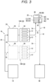
- the waste liquid unit 20 may be connected to a plurality of cell culturing systems 10. For example, by branching the upstream line 70 of the waste liquid channel 18, the flow channel 16 of a first cell culturing system 10A (solid line in Fig. 3 ) and the flow channel 16 of a second cell culturing system 10B (two-dot chain line in Fig. 3 ) are connected to the temporary storage unit 64. Therefore, the waste liquid unit 20 temporarily stores both the liquid that flows out of the flow channel 16 of the first cell culturing system 10A and the liquid that flows out of the flow channel 16 of the second cell culturing system 10B in one temporary storage unit 64. Then, the liquid stored in the temporary storage unit 64 is discharged to one or more waste liquid containers 62 via the downstream line 72.
- the cell culturing system 10 according to the present embodiment is basically formed as described above, and an operation thereof is hereinafter described.
- an operator sets a plurality of reactors 12 in the second casing 54 and sets the flow channel 16 in the flow path control mechanism unit 24.
- the operator accommodates the culture medium storage unit 14 in the culture medium accommodation box 60 of the installation base 56, and installs the waste liquid container 62 in the waste liquid accommodation box 61 of the installation base 56, whereas the temporary storage unit 64 is hung on the stand 66.
- the flow channel 16 illustrated in Fig. 2 is constructed between the culture medium storage unit 14 and each reactor 12, and the temporary storage unit 64 is arranged above the flow channel 16 in the gravity direction.
- the cell culturing system 10 sequentially performs a priming step, a culture medium replacement step, a seeding step, a culturing step, a stripping step, and a collection step in the culture treatment.
- the priming step the cleaning solution stored in a medical bag not illustrated is supplied to each reactor 12 via the flow channel 16, and air is removed from the reactor 12 and the flow channel 16.
- the culture medium replacement step the culture medium is supplied from the culture medium storage unit 14 to each reactor 12 via the primed flow channel 16, and the inside and outside of the hollow fiber 34 are filled with the culture medium.
- the cell solution stored in a medical bag not illustrated is supplied into the hollow fiber 34 of each reactor 12 via the IC route 42, and the cells are seeded on the inner peripheral surface of the hollow fiber 34.
- the cell culturing system 10 supplies the culture medium from the culture medium storage unit 14 into the hollow fiber 34 via both the IC route 42 and the EC route 44, and cultures the cells in the hollow fiber 34.
- carbon dioxide is discharged from the culture medium and oxygen is supplied to the culture medium by the gas exchanger 52.
- the culturing step is performed for a longer period of time (for example, several days) than other steps, so that the cells gradually propagates on the inner peripheral surface of the hollow fiber 34.
- the cell culturing system 10 may be configured to supply the culture medium to the reactor 12 via the EC route 44 without passing through the IC supply circuit 42b.
- the culture medium that flows through the EC route 44 to flow into the reactor 12 oozes from the outside to the inside of the hollow fiber 34 to be supplied to the cells.
- the culture medium that circulates in the IC circulation circuit 42a flows into the IC waste liquid circuit 46 while the second clamp 46a is opened.
- the culture medium that circulates in the EC circulation circuit 44a flows into the EC waste liquid circuit 48 while the third clamp 48a is opened.
- the culture medium flows through the waste liquid channel 18.
- the culture medium in the IC waste liquid circuit 46 and the EC waste liquid circuit 48 moves outside the second casing 54 by flowing into the upstream line 70 of the merging route 50. This culture medium flows upward in the gravity direction via the upstream line 70 and flows into the first storage unit 78 of the temporary storage unit 64.
- the temporary storage unit 64 continuously stores the culture medium in the first storage unit 78 until the culture medium exceeds the partition wall 82.
- the culture medium in the first storage unit 78 exceeds the partition wall 82
- the culture medium flows over the partition wall 82 (via the communication unit 84) to flow into the second storage unit 80.
- the culture medium moved to the second storage unit 80 flows to the downstream line 72 fixed to a lower portion of the second storage unit 80. That is, when an inflow amount of the culture medium exceeds a certain amount, the temporary storage unit 64 automatically discharges the culture medium to the downstream line 72 below the same.
- the culture medium discharged to the downstream line 72 flows downward in the gravity direction and flows into the waste liquid container 62 installed on the lower side of the installation base 56.
- the waste liquid container 62 has a volume capable of sufficiently storing the culture medium, and may significantly reduce the number of times of replacement of the waste liquid container 62 at the culturing step.
- the temporary storage unit 64 arranged above the flow channel 16 and the reactor 12 in the gravity direction may apply the positive pressure to the flow channel 16 via the culture medium in the first storage unit 78 and the upstream line 70. Therefore, in the EC circulation circuit 44a, the positive pressure of the culture medium is applied, so that it is possible to suppress an excessive inflow of air in the gas exchanger 52 and to stably mix the air and the culture medium. As a result, in the cell culturing system 10, the inflow of air bubbles into the flow channel 16 is significantly suppressed.
- the atmosphere open unit 86 provided in the temporary storage unit 64 may apply the atmospheric pressure to the culture medium in the first storage unit 78 and the upstream line 70, thereby applying the positive pressure to the flow channel 16 even in a case where the amount of the culture medium is small. Especially, since the vent mechanism 88 is employed as the atmosphere open unit 86, it is possible to avoid leakage of the culture medium from the temporary storage unit 64.
- the cell culturing system 10 guides the stripping solution stored in a medical bag not illustrated into the hollow fiber 34 of the reactor 12 via the IC route 42, and strips the cultured (propagated) cells.
- the cell culturing system 10 supplies the culture medium to the IC route 42 to allow the cells stripped at the stripping step to flow out of the reactor 12 and move to a collection bag not illustrated.
- the cell culturing system 10 may satisfactorily store the cells cultured in the reactor 12 in the collection bag. Especially, the cell culturing system 10 may stably apply the positive pressure to the flow channel 16, and may reduce a workload of the operator by reducing the number of times of replacement, removal and the like of the waste liquid container 62 even when a large amount of culture medium is used.
- the present invention is not limited to the above-described embodiment, and various modifications may be made in accordance with the gist of the invention.
- the cell culturing system 10 may be configured to perform the culture treatment by one reactor 12 without using a plurality of reactors 12. In a case of increasing the number of cultured cells in the culture treatment, a large-sized reactor 12 may be applied.
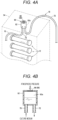
- the temporary storage unit 90 may be provided on an upper side in the second casing 54 that accommodates a plurality of reactors 12 (or the first casing 26: refer to Fig. 1 ). In this case also, the temporary storage unit 90 is arranged above the reactor 12 and the flow channel 16 in the gravity direction.
- the temporary storage unit 90 is formed of a small and hard container 92 in such a manner that a volume does not change in the second casing 54 (other mechanisms are not pressed by the flexible bag).
- the partition wall 82 (refer to Fig. 1 ) is not provided inside the container 92, and a storage space 92a enclosed by an inner surface of the container 92 is formed.
- Each of the upstream line 70 and the downstream line 72 of the waste liquid channel 18 is connected to a lower end of the container 92 of the temporary storage unit 90.
- the upstream line 70 is extended upward in the gravity direction from a connection site of the flow channel 16 (refer to Fig. 2 ).
- the downstream line 72 temporarily directed upward in the gravity direction from a lower portion of the container 92 in the second casing 54, thereby being exposed outside the second casing 54.
- the downstream line 72 is extended downward in the gravity direction and is connected to the waste liquid container 62 (refer to Fig. 1 ) installed below the second casing 54 in the gravity direction.
- the atmosphere open unit 86 that applies the atmospheric pressure to the culture medium that flows into the storage space 92a is provided on an upper end of the container 92 of the temporary storage unit 90.
- the atmosphere open unit 86 includes the vent mechanism 88 that permeates gas and blocks permeation of a liquid.
- the atmosphere open unit 86 may have a configuration in which the upper end of the container 92 is simply opened.
- the temporary storage unit 90 formed as described above may also obtain an effect similar to that of the temporary storage unit 64 described above. That is, the culture medium that flows into the temporary storage unit 90 from the flow channel 16 via the upstream line 70 is temporarily stored in the storage space 92a of the container 92. When the atmospheric pressure is applied to the culture medium in the container 92 from the atmosphere open unit 86, the positive pressure may be applied to the flow channel 16 via the culture medium of the upstream line 70.
- the temporary storage unit 90 provided in the second casing 54 may avoid disadvantages such as careless dropping of the temporary storage unit 90 by an operator or the like.
- the culture medium in the storage space 92a is guided to the downstream line 72 by a siphon effect.
- the culture medium is temporarily directed upward in the gravity direction in the downstream line 72, then guided downward in the gravity direction, and stored in the waste liquid container 62.
- the culture medium is temporarily stored in the temporary storage unit 90 and then smoothly discharged to the waste liquid container 62, and does not accumulate in a large amount in the container 92.
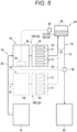
- the cell culturing system 10 may apply a temporary storage unit 94 without the partition wall 82, and include a sensor 96 that detects a weight or a liquid level of the temporary storage unit 94, and a valve 98 that opens and closes the downstream line 72.
- the sensor 96 and the valve 98 are connected to the control unit 32 of the cell culturing system 10 so as to be able to communicate by wire or wirelessly.
- the control unit 32 closes the valve 98 in a normal state, monitors the amount of liquid flowing into the temporary storage unit 94 on the basis of detection information of the sensor 96, and opens the valve 98 in a case where the amount of liquid exceeds a predetermined threshold. Even in this case, the cell culturing system 10 may stably apply the positive pressure to the flow channel 16.
- An aspect of the present invention is a cell culturing system 10 including a reactor 12 that cultures cells on the basis of a flow of a culture medium, a flow channel 16 that allows the culture medium to flow into and out of the reactor 12, a waste liquid channel 18 connected to the flow channel 16, the waste liquid channel 18 discharging the culture medium from the flow channel 16, and a waste liquid container 62 connected to the waste liquid channel 18, the waste liquid container 62 being capable of storing the culture medium passing through the waste liquid channel 18, in which the waste liquid channel 18 includes a temporary storage unit 64, 90, 94 capable of temporarily storing the culture medium, the waste liquid container 62 is located below the temporary storage unit 64, 90, 94 in a gravity direction, and the temporary storage unit 64, 90, 94 is provided above the flow channel 16 in the gravity direction, temporarily stores the culture medium discharged from the flow channel 16, and allows the culture medium to flow out toward the waste liquid container 62.
- the temporary storage unit 64, 90, 94 is located above the flow channel 16 in the gravity direction, so that the positive pressure may be appropriately applied to the reactor 12 and the flow channel 16 via the culture medium of the temporary storage unit 64, 90, 94.
- the cell culturing system 10 may suppress the excessive inflow of air into the reactor 12 and the flow channel 16. Since the waste liquid container 62 is located below the temporary storage unit 64, 90, 94 in the gravity direction, the cell culturing system 10 may reduce a workload in replacement, removal and the like of the waste liquid container 62.
- the waste liquid container 62 is provided below an installation site of the reactor 12 in the gravity direction. This makes it easier for the operator of the cell culturing system 10 to perform operations such as replacement and removal of the waste liquid container 62.
- a first storage unit 78, a second storage unit 80, a partition wall 82 that partitions the first storage unit 78 and the second storage unit 80, and a communication unit 84 through which the first storage unit 78 communicates with the second storage unit 80 above the partition wall 82 in the gravity direction are provided inside the temporary storage unit 64, 94, the waste liquid channel 18 includes an upstream line 70 through which the flow channel 16 communicates with the first storage unit 78, and a downstream line 72 through which the second storage unit 80 communicates with the waste liquid container 62, and the downstream line 72 is extended downward in the gravity direction from the second storage unit 80.
- the culture medium stored in the first storage unit 78 may apply an appropriate positive pressure to the reactor 12 and the flow channel 16.
- the first storage unit 78 and the second storage unit 80 are located at positions adjacent to each other in a direction orthogonal to the gravity direction, and a volume of the first storage unit 78 is larger than a volume of the second storage unit 80.
- the temporary storage unit 64 may apply a large positive pressure from the first storage unit 78 to the reactor 12 and the flow channel 16.
- the temporary storage unit 90 includes an atmosphere open unit 86 that applies an atmospheric pressure to the culture medium that flows into the temporary storage unit 90, and the atmosphere open unit 86 includes a vent mechanism 88 that permeates gas and blocks permeation of a liquid. As a result, even in the configuration in which the cell culturing system 10 includes the atmosphere open unit 86, leakage of the culture medium from the temporary storage unit 90 is suppressed.
- the waste liquid channel 18 includes an upstream line 70 through which the flow channel 16 communicates with the temporary storage unit 90, and a downstream line 72 through which the temporary storage unit 90 communicates with the waste liquid container 62, and the downstream line 72 is temporarily directed upward in the gravity direction from a lower portion of the temporary storage unit 90, then directed downward in the gravity direction.
- the cell culturing system 10 may discharge the culture medium from the temporary storage unit 90 to the waste liquid container 62 while applying the positive pressure to the reactor 12 and the flow channel 16 by the culture medium stored in the temporary storage unit 90.
- the temporary storage unit 64, 94 is arranged outside a casing (second casing 54) that accommodates the reactor 12. As a result, the operator may easily set the temporary storage unit 64, 94 when preparing the cell culturing system 10. The operator may visually check the culture medium in the temporary storage unit 64, 94 located outside and recognize a waste liquid state of the culture medium.
- the temporary storage unit 90 is arranged inside a casing (second casing 54) that accommodates the reactor 12.
- the cell culturing system 10 may avoid disadvantages such as careless dropping of the temporary storage unit 90 by the operator or the like.
- the flow channel 16 includes a circulation circuit (EC circulation circuit 44a) that circulates the culture medium with the reactor 12, and a supply circuit (EC supply circuit 44b) that supplies the culture medium to the circulation circuit, and the circulation circuit includes a gas exchanger 52 that mixes gas with the culture medium on an upstream side from the reactor 12 in a flow direction of the culture medium, and the waste liquid channel 18 is connected to a downstream side from the reactor 12 in the flow direction of the culture medium.
- the cell culturing system 10 may apply an appropriate positive pressure to the circulation circuit including the gas exchanger 52 via the culture medium in the temporary storage unit 64, 90, 94 and the waste liquid channel 18, and may suppress an excessive inflow of gas in the gas exchanger 52.
- a plurality of reactors 12 is provided, and the culture medium that flows through the plurality of reactors 12 is collectively discharged to the waste liquid channel 18 and the waste liquid container 62.
- the cell culturing system 10 may efficiently culture the cells by the plurality of reactors 12.
- the cell culturing system 10 may stably waste the culture medium by the waste liquid container 62 and the temporary storage unit 64, 90, 94 by using the plurality of reactors 12 even if a large amount of the culture medium flows.
Landscapes
- Health & Medical Sciences (AREA)
- Chemical & Material Sciences (AREA)
- Wood Science & Technology (AREA)
- Zoology (AREA)
- Engineering & Computer Science (AREA)
- Bioinformatics & Cheminformatics (AREA)
- Organic Chemistry (AREA)
- Life Sciences & Earth Sciences (AREA)
- Biotechnology (AREA)
- Sustainable Development (AREA)
- Microbiology (AREA)
- Biochemistry (AREA)
- General Engineering & Computer Science (AREA)
- General Health & Medical Sciences (AREA)
- Genetics & Genomics (AREA)
- Biomedical Technology (AREA)
- Analytical Chemistry (AREA)
- Clinical Laboratory Science (AREA)
- Immunology (AREA)
- Apparatus Associated With Microorganisms And Enzymes (AREA)
Abstract
Description
- The present invention relates to a cell culturing system that cultures cells in a reactor by allowing a culture medium to flow into and out of the reactor.
- In regenerative medicine, cells of a living body are collected and cultured, and the cultured cells are administered to a patient. In cell culture treatment, for example, as disclosed in
JP 2017-143775 A - In this type of cell culturing system, a waste liquid unit formed of a medical bag and the like is hung on a stand, and the waste liquid unit is arranged above the reactor in a gravity direction. As a result, the cell culturing system may apply a positive pressure to the reactor and the flow channel via the culture medium flowing into the waste liquid unit, and may suppress an excessive inflow of air (air bubbles) into the reactor.
- However, in a case where a large amount of culture medium is discharged to the waste liquid unit over a long period of time, when a small-capacity medical bag is used, replacement work of the waste liquid unit is frequently required, and a workload of an operator increases. Even if the waste liquid unit is formed of a large tank and the like, the operator needs to perform an operation of removing the waste liquid unit storing a large amount of culture medium above the reactor in the gravity direction, so that a load also increases.
- The present invention has been made in view of the above-described problems, and an object thereof is to provide a cell culturing system capable of appropriately applying a positive pressure to a reactor and a flow channel, and capable of reducing a workload such as replacement and removal of a waste liquid unit.
- In order to achieve the above-described object, an aspect of the present invention is a cell culturing system including a reactor that cultures cells on the basis of a flow of a culture medium, a flow channel that allows the culture medium to flow into and out of the reactor, a waste liquid channel connected to the flow channel, the waste liquid channel discharging the culture medium from the flow channel, and a waste liquid container connected to the waste liquid channel, the waste liquid container being capable of storing the culture medium passing through the waste liquid channel, in which the waste liquid channel includes a temporary storage unit capable of temporarily storing the culture medium, the waste liquid container is located below the temporary storage unit in a gravity direction, and the temporary storage unit is provided above the flow channel in the gravity direction, temporarily stores the culture medium discharged from the flow channel, and allows the culture medium to flow out toward the waste liquid container.
- The cell culturing system described above may appropriately apply a positive pressure to a reactor and a flow channel, and reduce a workload in replacement, removal and the like of a waste liquid unit.
-
-
Fig. 1 is a perspective view schematically illustrating an entire configuration of a cell culturing system according to an embodiment of the present invention. -
Fig. 2 is a circuit diagram illustrating a flow channel and a flow path control mechanism unit between a culture medium storage unit and a reactor. -
Fig. 3 is an explanatory view schematically illustrating a waste liquid channel and a waste liquid unit. -
Fig. 4A is a perspective view illustrating a temporary storage unit according to a first variation.Fig. 4B is a cross-sectional view of the temporary storage unit according to the first variation. -
Fig. 5 is an explanatory view schematically illustrating a waste liquid channel and a waste liquid unit according to a second variation. - Preferred embodiments of the present invention are hereinafter described in detail with reference to the accompanying drawings.
- As illustrated in
Fig. 1 , acell culturing system 10 according to an embodiment of the present invention is formed as a stationary device installed in a sterile room and the like, and performs culture treatment to culture cells of a living body in regenerative medicine. Therefore, thecell culturing system 10 is equipped with areactor 12, which is a cell culturing container. Thecell culturing system 10 discharges lactic acid, carbon dioxide and the like (including unused culture medium and oxygen) generated during cell culture from thereactor 12 while supplying the culture medium and oxygen to thereactor 12, thereby performing the cell culture over a long period of time. - The cells of the living body are not especially limited, and may include, for example, cells contained in the blood (T cells and the like), and stem cells (ES cells, iPS cells, mesenchymal stem cells and the like). As the culture medium, an appropriate culture medium may be selected according to the cells of the living body, and there is the culture medium prepared by adding various amino acids, vitamins, serum and the like to a balanced salt solution (BSS) as a basic solution, for example.
- In addition to the
reactor 12, thecell culturing system 10 includes a culturemedium storage unit 14 that stores a culture medium, aflow channel 16 provided between thereactor 12 and the culturemedium storage unit 14, a wasteliquid channel 18 that discharges the culture medium from theflow channel 16, and awaste liquid unit 20 that stores the culture medium that flows through the wasteliquid channel 18. Thecell culturing system 10 according to the present embodiment is equipped with a plurality of (five inFig. 1 )reactors 12, thereby improving efficiency of the culture treatment. That is, thecell culturing system 10 is configured to obtain several times the number of cells as compared with the culture by onereactor 12 without significantly changing a culturing period by allowing the culture medium to flow through each of the plurality ofreactors 12 and culturing the cells in eachreactor 12. - A hard (or soft) tank capable of storing a large amount of culture medium is applied as the culture
medium storage unit 14 in order to supply the culture medium to eachreactor 12. For example, the tank preferably has a volume of about 5 L to 30 L, and this reduces a workload of frequently replacing the culturemedium storage unit 14 during the culture treatment. A flexible medical bag and the like may be applied as the culturemedium storage unit 14. - The
flow channel 16 is formed of a plurality of tubes 22 (inFig. 1 , only thetube 22 connected to the culturemedium storage unit 14 is illustrated). Eachtube 22 is connected to the culturemedium storage unit 14 and some medical bags not illustrated, and is connected to eachreactor 12. As a result, thecell culturing system 10 supplies and discharges the culture medium in the culturemedium storage unit 14 and the liquid (cell solution, cleaning solution, stripping solution and the like) in each medical bag to and from thereactor 12 via eachtube 22. - The cell solution is a liquid containing cells seeded (to be cultured) in the
reactor 12. The cleaning solution is a liquid used when priming thereactor 12 and theflow channel 16. Examples of the cleaning solution include buffer solutions such as phosphate buffered salts (PBS) and tris-buffered saline (TBS), or a physiological saline, for example. The stripping solution is a liquid that strips the cells cultured by the culture treatment. As the stripping solution, for example, trypsin, EDTA solution and the like may be used. - When the
cell culturing system 10 is constructed, theflow channel 16 is set so as to pass through a flow pathcontrol mechanism unit 24. The flow pathcontrol mechanism unit 24 is equipped with afirst casing 26 that accommodates a part of theflow channel 16. The flow pathcontrol mechanism unit 24 is equipped with a plurality ofclamps 28 that opens and closes apredetermined tube 22, a plurality ofpumps 30 that allows the liquid in thetube 22 to flow, and acontrol unit 32 that controls operations of eachclamp 28 and eachpump 30 in the first casing 26 (refer toFig. 2 ). That is, the flow pathcontrol mechanism unit 24 allows the liquid in theflow channel 16 to flow under the operation of thepump 30 while selectively switching thetube 22 through which the liquid flows by opening and closing eachclamp 28. - In addition to the plurality of
tubes 22, theflow channel 16 may be equipped with a cassette (not illustrated) including a plurality of liquid flow paths, the cassette to whichseveral tubes 22 are connected. In this case, as the cassette is set in thefirst casing 26, this is arranged in theclamp 28 of the flow pathcontrol mechanism unit 24, and opening/closing, switching and the like of the flow path in the cassette are performed by theclamp 28. - In order to increase a culturing area of each
reactor 12 connected to theflow channel 16, for example, a structure including ahollow fiber 34 is preferably applied. Specifically, eachreactor 12 is equipped with a plurality of (for example, 10,000 or more)hollow fibers 34 and acase 36 that accommodates the plurality ofhollow fibers 34 in an axial direction. - Each
hollow fiber 34 includes an inner cavity not illustrated penetrating in an extending direction, and cells are seeded on an inner peripheral surface forming the inner cavity. Eachhollow fiber 34 includes a plurality of pores not illustrated through which the inner cavity communicates with the outside, and each pore does not permeate cells or proteins but permeates a solution or a small-molecular substance. Therefore, the culture medium, a predetermined gas component and the like are supplied to the cells on the inner peripheral surface of thehollow fiber 34 through the pores. Hereinafter, a configuration in which the liquid is allowed to mainly flow through the inner cavity of thehollow fiber 34 is also referred to as intra capillary (IC), and a configuration in which the liquid is allowed to mainly flow outside thehollow fiber 34 is also referred to as extra capillary (EC). - Examples of a material forming the
hollow fiber 34 are not especially limited, and include polyolefin resins such as polypropylene and polyethylene, and polymer materials such as polysulfone, polyethersulfone, polyacrylonitrile, polytetrafluoroethylene, polystyrene, polymethylmethacrylate, cellulose acetate, cellulose triacetate, and regenerated cellulose. - The
case 36 is formed into a cylindrical shape and has rigidity. Thecase 36 is equipped with afirst IC terminal 36a, asecond IC terminal 36b, afirst EC terminal 36c, and asecond EC terminal 36d connected to eachtube 22. Thefirst IC terminal 36a is provided at one end in the axial direction of thecase 36 and communicates with the inner cavity of thehollow fiber 34. Thesecond IC terminal 36b is provided at the other end in the axial direction of thecase 36 and communicates with the inner cavity of thehollow fiber 34. Thefirst EC terminal 36c is provided near the other end of a side surface of thecase 36, and communicates with a space outside thehollow fiber 34 in thecase 36. Thesecond EC terminal 36d is provided near the one end of the side surface of thecase 36, and communicates with the space outside thehollow fiber 34 in thecase 36. - Hereinafter, configurations of the
flow channel 16 between onereactor 12 and the culturemedium storage unit 14, and the flow pathcontrol mechanism unit 24 are specifically described with reference toFig. 2 . - The
flow channel 16 includes a culturemedium delivery route 40 connected to the culturemedium storage unit 14, and an IC route 42 (internal route) and an EC route 44 (external route) branched from the culturemedium delivery route 40. TheIC route 42 is a channel that supplies the liquid into the inner cavity of thehollow fiber 34, and the liquid such as the cleaning solution, cell solution, culture medium, and stripping solution flows therethrough. TheEC route 44 is a channel that supplies the liquid to the outside of the hollow fiber 34 (in the case 36), and the liquid such as the cleaning solution, culture medium, and stripping solution flows therethrough. - The culture
medium delivery route 40 is provided with afirst clamp 40a that opens or blocks the supply of the culture medium from the culturemedium storage unit 14. - The
IC route 42 includes anIC circulation circuit 42a capable of circulating the liquid with thereactor 12, and anIC supply circuit 42b capable of allowing the liquid to flow from the culturemedium delivery route 40 to theIC circulation circuit 42a. TheIC circulation circuit 42a is provided with anIC circulation pump 30a for circulating the liquid. TheIC supply circuit 42b is provided with anIC supply pump 30b for allowing the liquid to flow from the culturemedium delivery route 40 to theIC circulation circuit 42a. Although not illustrated, in addition to the culturemedium storage unit 14, thetube 22 connected to each medical bag storing the cleaning solution, cell solution, stripping solution and the like is connected to theIC supply circuit 42b. - The
IC circulation circuit 42a is connected to thefirst IC terminal 36a and thesecond IC terminal 36b of thereactor 12. Therefore, the liquid that circulates in theIC circulation circuit 42a flows through the inner cavity of thehollow fiber 34 under the operation of theIC circulation pump 30a. - The IC
waste liquid circuit 46 is connected to a downstream side from thereactor 12 on theIC circulation circuit 42a. The ICwaste liquid circuit 46 forms a part of thewaste liquid channel 18 and is connected to a mergingroute 50 of thewaste liquid channel 18. The ICwaste liquid circuit 46 is provided with asecond clamp 46a that opens or blocks discharge of the liquid from theIC circulation circuit 42a. - In contrast, the
EC route 44 includes anEC circulation circuit 44a capable of circulating the liquid with thereactor 12, and anEC supply circuit 44b capable of allowing the liquid to flow from the culturemedium delivery route 40 to theEC circulation circuit 44a. TheEC circulation circuit 44a is provided with anEC circulation pump 30c for circulating the liquid. TheEC supply circuit 44b is provided with anEC supply pump 30d for allowing the liquid to flow from the culturemedium delivery route 40 to theEC circulation circuit 44a. Although not illustrated, in addition to the culturemedium storage unit 14, thetube 22 connected to each medical bag storing the cleaning solution, stripping solution and the like is connected to theEC supply circuit 44b. - The
EC circulation circuit 44a is connected to thefirst EC terminal 36c and thesecond EC terminal 36d of thereactor 12. Therefore, the liquid that circulates in theEC circulation circuit 44a flows through thecase 36 under the operation of theEC circulation pump 30c. Agas exchanger 52 is provided on an upstream side from thereactor 12 on theEC circulation circuit 44a. Thegas exchanger 52 has a function of discharging carbon dioxide mixed in the culture medium and mixing a predetermined gas component (nitrogen N2: 75%, oxygen O2: 20%, carbon dioxide CO2: 5%) with the culture medium. A structure of thegas exchanger 52 is not especially limited, and a structure in which a plurality of hollow fibers is provided in the case may be applied as is the case with thereactor 12. - An EC
waste liquid circuit 48 is connected to a downstream side from thereactor 12 on theEC circulation circuit 44a. The ECwaste liquid circuit 48 forms a part of thewaste liquid channel 18 and is connected to the mergingroute 50 of thewaste liquid channel 18. The ECwaste liquid circuit 48 is provided with athird clamp 48a that opens or blocks discharge of the liquid from theEC circulation circuit 44a. - As described above, in a case where a plurality of (five)
reactors 12 is provided, thecell culturing system 10 may be equipped with a plurality ofIC circulation circuits 42a and a plurality ofEC circulation circuits 44a corresponding to therespective reactors 12. That is, another IC circulation circuit and another EC circulation circuit not illustrated that circulate the liquid in anotherreactor 12 are connected in parallel to a branch point X between theIC supply pump 30b and theIC circulation circuit 42a and a branch point Y between theEC supply pump 30d and theEC circulation circuit 44a, respectively. - With reference to
Fig. 1 again, thecell culturing system 10 includes asecond casing 54 that accommodates eachreactor 12 at a position adjacent to thefirst casing 26 that forms the flow pathcontrol mechanism unit 24. Thesecond casing 54 has a function of keeping temperature of an accommodation chamber of eachreactor 12 at 37°C. That is, thecell culturing system 10 may easily form an environment suitable for the cell culture of eachreactor 12 by using thesecond casing 54 different from thefirst casing 26 of the flow pathcontrol mechanism unit 24. Thecell culturing system 10 is not limited to the configuration in which eachreactor 12 and theflow channel 16 are accommodated in a plurality of casings, and may be configured to accommodate them in one casing. - The
second casing 54 may be formed to include a part (clamp 28, pump 30 and the like) of the flow pathcontrol mechanism unit 24 therein. For example, thesecond clamp 46a on the ICwaste liquid circuit 46 and thethird clamp 48a on the ECwaste liquid circuit 48 are provided in thesecond casing 54. Thesecond casing 54 is preferably configured to rotatably fix eachreactor 12 in a gravity direction or a horizontal direction, or around the axis of thecase 36. As a result, air in eachreactor 12 is easily discharged from thecase 36. - Furthermore, the
cell culturing system 10 is equipped with aninstallation base 56 on which thefirst casing 26 and thesecond casing 54 are installed. Theinstallation base 56 includes atop plate 58 on which thefirst casing 26 and thesecond casing 54 are placed, and thetop plate 58 is supported at a predetermined height (about 50 cm to 150 cm) by a side wall and the like of theinstallation base 56. The culturemedium storage unit 14 is accommodated in a culturemedium accommodation box 60 of theinstallation base 56 provided below thetop plate 58. - The
waste liquid channel 18 of thecell culturing system 10 is connected to theflow channel 16 described above and is connected to thewaste liquid unit 20, thereby discharging the liquid such as the culture medium, the cleaning solution and the like from theflow channel 16 to thewaste liquid unit 20. Thewaste liquid channel 18 includes the ICwaste liquid circuit 46 of theIC route 42, the ECwaste liquid circuit 48 of theEC route 44, and the merging route 50 (refer toFig. 2 ). The mergingroute 50 of thewaste liquid channel 18 is provided so as to be extended from the interior of the second casing 54 (or the first casing 26) to the outside. - As illustrated in
Figs. 1 and3 , thewaste liquid unit 20 includes awaste liquid container 62 that is connected to the most downstream side of thewaste liquid channel 18 and capable of storing the culture medium passing through thewaste liquid channel 18. Thewaste liquid channel 18 includes atemporary storage unit 64 capable of temporarily storing the culture medium on an upstream side from thewaste liquid container 62. - In the
waste liquid container 62, a hard (or soft) tank having a large volume is applied for storing the culture medium used in eachreactor 12. For example, the tank preferably has the volume of about 5 L to 30 L. As a result, a workload of frequently replacing thewaste liquid container 62 is reduced. Alternatively, a flexible medical bag and the like may be applied as thewaste liquid container 62. - The
waste liquid container 62 is accommodated in a wasteliquid accommodation box 61 of theinstallation base 56 provided below thetop plate 58. That is, thewaste liquid container 62 is provided below thetemporary storage unit 64 in the gravity direction. Thewaste liquid container 62 according to the present embodiment is located below thefirst casing 26 and thesecond casing 54 accommodating eachreactor 12 in the gravity direction. AlthoughFig. 1 illustrates a state in which thewaste liquid container 62 is exposed from the wasteliquid accommodation box 61, the wasteliquid accommodation box 61 may have a configuration of hermetically sealing thewaste liquid container 62. - In contrast, the
temporary storage unit 64 temporarily stores the liquid discharged from theflow channel 16 and then allows the same to flow out toward thewaste liquid container 62. Therefore, a volume of thetemporary storage unit 64 is sufficiently smaller than a volume of thewaste liquid container 62. Thetemporary storage unit 64 is, for example, hung on astand 66 fixed to theinstallation base 56, and is located above thefirst casing 26 and thesecond casing 54 accommodating the plurality ofreactors 12 in the gravity direction. In other words, thetemporary storage unit 64 is arranged above thereactor 12 and theflow channel 16 in the gravity direction. A height of thetemporary storage unit 64 is not especially limited, and this may be set in a range of 150 cm to 180 cm, for example, and is set to have a predetermined difference (range of 10 cm to 80 cm) with respect to the heights of thereactor 12 and theflow channel 16. - The waste liquid channel 18 (merging route 50) includes an
upstream line 70 provided between theflow channel 16 and thetemporary storage unit 64 via the ICwaste liquid circuit 46 and the ECwaste liquid circuit 48, and adownstream line 72 provided between thetemporary storage unit 64 and thewaste liquid container 62. Theupstream line 70 and thedownstream line 72 are formed of atube 73 including a flow path inside. Theupstream line 70 is extended upward in the gravity direction from thesecond casing 54 and is connected to a lower portion of thetemporary storage unit 64. Thedownstream line 72 is extended downward in the gravity direction from thetemporary storage unit 64 and is connected to an upper portion of thewaste liquid container 62. - A flexible medical bag is applied as the
temporary storage unit 64. Thetemporary storage unit 64 includes a sealedportion 74 obtained by sealing outer peripheries of two sheets forming the medical bag, and includes astorage space 76 inside the sealedportion 74 and between the two sheets. Theupstream line 70 and thedownstream line 72 are coupled to the sealedportion 74 on a lower side of the temporary storage unit 64 (hereinafter, referred to as a lower sealedportion 74a). Thetemporary storage unit 64 may be formed of a hard container. - A
partition wall 82 that separates a lower side of thestorage space 76 into afirst storage unit 78 and asecond storage unit 80 is provided inside thetemporary storage unit 64. Thepartition wall 82 is continued to the lower sealedportion 74a and is extended upward in the gravity direction from the lower sealedportion 74a. Thepartition wall 82 is formed by, for example, sealing the two sheets forming the medical bag. Alternatively, thepartition wall 82 may be formed by welding an edge of a plate member and each sheet in a state in which the plate member having a predetermined thickness in a direction orthogonal to two sheet surfaces is interposed between the two sheets. - In the
temporary storage unit 64, a communication unit 84 (a part of the storage space 76) through which thefirst storage unit 78 communicates with thesecond storage unit 80 is provided above thepartition wall 82 in the gravity direction. That is, thestorage space 76 is formed of thecommunication unit 84 on the upper side in the gravity direction, and thefirst storage unit 78 and thesecond storage unit 80 adjacent to each other in a lateral direction (direction orthogonal to the gravity direction) of thepartition wall 82 below thecommunication unit 84 in the gravity direction. A flow path of theupstream line 70 fixed to the lower sealedportion 74a communicates with thefirst storage unit 78. A flow path of thedownstream line 72 fixed to the lower sealedportion 74a communicates with thesecond storage unit 80. - Therefore, the liquid that flows into the
temporary storage unit 64 from theupstream line 70 is first stored in thefirst storage unit 78, and when the liquid fills thefirst storage unit 78, the liquid goes over thepartition wall 82 and flows into thesecond storage unit 80. The liquid that flows into thesecond storage unit 80 flows out to the downstream line 72 (outside the temporary storage unit 64). - The
first storage unit 78 is configured to apply an appropriate pressure (positive pressure) to thereactor 12 and theflow channel 16 via the stored culture medium. For example, a volume of thefirst storage unit 78 is preferably set in a range of about 0.5 times to three times a volume of thesecond storage unit 80. An actual volume of thefirst storage unit 78 may be set to, for example, a range of 50 cc to 300 cc. - The
temporary storage unit 64 includes an atmosphereopen unit 86 that applies an atmospheric pressure to the liquid that flows into thefirst storage unit 78. In the present embodiment, the atmosphereopen unit 86 includes avent mechanism 88 that permeates gas and blocks permeation of a liquid. As a result, thevent mechanism 88 may apply the atmospheric pressure to the liquid in thefirst storage unit 78 without leaking the liquid that flows into thestorage space 76 to the outside. The atmosphereopen unit 86 is not limited to thevent mechanism 88, and may be formed of an opening that simply opens an upper side in the gravity direction of thetemporary storage unit 64. - As illustrated in
Fig. 3 , thewaste liquid unit 20 may be connected to a plurality ofcell culturing systems 10. For example, by branching theupstream line 70 of thewaste liquid channel 18, theflow channel 16 of a firstcell culturing system 10A (solid line inFig. 3 ) and theflow channel 16 of a secondcell culturing system 10B (two-dot chain line inFig. 3 ) are connected to thetemporary storage unit 64. Therefore, thewaste liquid unit 20 temporarily stores both the liquid that flows out of theflow channel 16 of the firstcell culturing system 10A and the liquid that flows out of theflow channel 16 of the secondcell culturing system 10B in onetemporary storage unit 64. Then, the liquid stored in thetemporary storage unit 64 is discharged to one or morewaste liquid containers 62 via thedownstream line 72. - The
cell culturing system 10 according to the present embodiment is basically formed as described above, and an operation thereof is hereinafter described. - As illustrated in
Fig. 1 , in thecell culturing system 10, before the culture treatment is performed, an operator sets a plurality ofreactors 12 in thesecond casing 54 and sets theflow channel 16 in the flow pathcontrol mechanism unit 24. The operator accommodates the culturemedium storage unit 14 in the culturemedium accommodation box 60 of theinstallation base 56, and installs thewaste liquid container 62 in the wasteliquid accommodation box 61 of theinstallation base 56, whereas thetemporary storage unit 64 is hung on thestand 66. As a result, theflow channel 16 illustrated inFig. 2 is constructed between the culturemedium storage unit 14 and eachreactor 12, and thetemporary storage unit 64 is arranged above theflow channel 16 in the gravity direction. - After the above-described setting, the
cell culturing system 10 sequentially performs a priming step, a culture medium replacement step, a seeding step, a culturing step, a stripping step, and a collection step in the culture treatment. At the priming step, the cleaning solution stored in a medical bag not illustrated is supplied to eachreactor 12 via theflow channel 16, and air is removed from thereactor 12 and theflow channel 16. At the culture medium replacement step, the culture medium is supplied from the culturemedium storage unit 14 to eachreactor 12 via the primedflow channel 16, and the inside and outside of thehollow fiber 34 are filled with the culture medium. At the seeding step, the cell solution stored in a medical bag not illustrated is supplied into thehollow fiber 34 of eachreactor 12 via theIC route 42, and the cells are seeded on the inner peripheral surface of thehollow fiber 34. - Then, as illustrated in
Fig. 2 , at the culturing step, thecell culturing system 10 supplies the culture medium from the culturemedium storage unit 14 into thehollow fiber 34 via both theIC route 42 and theEC route 44, and cultures the cells in thehollow fiber 34. At that time, carbon dioxide is discharged from the culture medium and oxygen is supplied to the culture medium by thegas exchanger 52. The culturing step is performed for a longer period of time (for example, several days) than other steps, so that the cells gradually propagates on the inner peripheral surface of thehollow fiber 34. Thecell culturing system 10 may be configured to supply the culture medium to thereactor 12 via theEC route 44 without passing through theIC supply circuit 42b. The culture medium that flows through theEC route 44 to flow into thereactor 12 oozes from the outside to the inside of thehollow fiber 34 to be supplied to the cells. - At the culturing step, the culture medium that circulates in the
IC circulation circuit 42a flows into the ICwaste liquid circuit 46 while thesecond clamp 46a is opened. The culture medium that circulates in theEC circulation circuit 44a flows into the ECwaste liquid circuit 48 while thethird clamp 48a is opened. As a result, the culture medium flows through thewaste liquid channel 18. The culture medium in the ICwaste liquid circuit 46 and the ECwaste liquid circuit 48 moves outside thesecond casing 54 by flowing into theupstream line 70 of the mergingroute 50. This culture medium flows upward in the gravity direction via theupstream line 70 and flows into thefirst storage unit 78 of thetemporary storage unit 64. - As illustrated in
Fig. 3 , thetemporary storage unit 64 continuously stores the culture medium in thefirst storage unit 78 until the culture medium exceeds thepartition wall 82. When the culture medium in thefirst storage unit 78 exceeds thepartition wall 82, the culture medium flows over the partition wall 82 (via the communication unit 84) to flow into thesecond storage unit 80. The culture medium moved to thesecond storage unit 80 flows to thedownstream line 72 fixed to a lower portion of thesecond storage unit 80. That is, when an inflow amount of the culture medium exceeds a certain amount, thetemporary storage unit 64 automatically discharges the culture medium to thedownstream line 72 below the same. - The culture medium discharged to the
downstream line 72 flows downward in the gravity direction and flows into thewaste liquid container 62 installed on the lower side of theinstallation base 56. Thewaste liquid container 62 has a volume capable of sufficiently storing the culture medium, and may significantly reduce the number of times of replacement of thewaste liquid container 62 at the culturing step. - Then, the
temporary storage unit 64 arranged above theflow channel 16 and thereactor 12 in the gravity direction may apply the positive pressure to theflow channel 16 via the culture medium in thefirst storage unit 78 and theupstream line 70. Therefore, in theEC circulation circuit 44a, the positive pressure of the culture medium is applied, so that it is possible to suppress an excessive inflow of air in thegas exchanger 52 and to stably mix the air and the culture medium. As a result, in thecell culturing system 10, the inflow of air bubbles into theflow channel 16 is significantly suppressed. - The atmosphere
open unit 86 provided in thetemporary storage unit 64 may apply the atmospheric pressure to the culture medium in thefirst storage unit 78 and theupstream line 70, thereby applying the positive pressure to theflow channel 16 even in a case where the amount of the culture medium is small. Especially, since thevent mechanism 88 is employed as the atmosphereopen unit 86, it is possible to avoid leakage of the culture medium from thetemporary storage unit 64. - At the stripping step after the culturing step, the
cell culturing system 10 guides the stripping solution stored in a medical bag not illustrated into thehollow fiber 34 of thereactor 12 via theIC route 42, and strips the cultured (propagated) cells. At the collection step after the stripping step, thecell culturing system 10 supplies the culture medium to theIC route 42 to allow the cells stripped at the stripping step to flow out of thereactor 12 and move to a collection bag not illustrated. - Through the above-described steps, the
cell culturing system 10 may satisfactorily store the cells cultured in thereactor 12 in the collection bag. Especially, thecell culturing system 10 may stably apply the positive pressure to theflow channel 16, and may reduce a workload of the operator by reducing the number of times of replacement, removal and the like of thewaste liquid container 62 even when a large amount of culture medium is used. - The present invention is not limited to the above-described embodiment, and various modifications may be made in accordance with the gist of the invention. For example, the
cell culturing system 10 may be configured to perform the culture treatment by onereactor 12 without using a plurality ofreactors 12. In a case of increasing the number of cultured cells in the culture treatment, a large-sized reactor 12 may be applied. - As in a first variation illustrated in
Figs. 4A and 4B , thetemporary storage unit 90 may be provided on an upper side in thesecond casing 54 that accommodates a plurality of reactors 12 (or the first casing 26: refer toFig. 1 ). In this case also, thetemporary storage unit 90 is arranged above thereactor 12 and theflow channel 16 in the gravity direction. For example, thetemporary storage unit 90 is formed of a small andhard container 92 in such a manner that a volume does not change in the second casing 54 (other mechanisms are not pressed by the flexible bag). - The partition wall 82 (refer to
Fig. 1 ) is not provided inside thecontainer 92, and astorage space 92a enclosed by an inner surface of thecontainer 92 is formed. Each of theupstream line 70 and thedownstream line 72 of thewaste liquid channel 18 is connected to a lower end of thecontainer 92 of thetemporary storage unit 90. Theupstream line 70 is extended upward in the gravity direction from a connection site of the flow channel 16 (refer toFig. 2 ). In contrast, thedownstream line 72 temporarily directed upward in the gravity direction from a lower portion of thecontainer 92 in thesecond casing 54, thereby being exposed outside thesecond casing 54. Then, outside thesecond casing 54, thedownstream line 72 is extended downward in the gravity direction and is connected to the waste liquid container 62 (refer toFig. 1 ) installed below thesecond casing 54 in the gravity direction. - Furthermore, the atmosphere
open unit 86 that applies the atmospheric pressure to the culture medium that flows into thestorage space 92a is provided on an upper end of thecontainer 92 of thetemporary storage unit 90. The atmosphereopen unit 86 includes thevent mechanism 88 that permeates gas and blocks permeation of a liquid. The atmosphereopen unit 86 may have a configuration in which the upper end of thecontainer 92 is simply opened. - The
temporary storage unit 90 formed as described above may also obtain an effect similar to that of thetemporary storage unit 64 described above. That is, the culture medium that flows into thetemporary storage unit 90 from theflow channel 16 via theupstream line 70 is temporarily stored in thestorage space 92a of thecontainer 92. When the atmospheric pressure is applied to the culture medium in thecontainer 92 from the atmosphereopen unit 86, the positive pressure may be applied to theflow channel 16 via the culture medium of theupstream line 70. Especially, thetemporary storage unit 90 provided in thesecond casing 54 may avoid disadvantages such as careless dropping of thetemporary storage unit 90 by an operator or the like. - The culture medium in the
storage space 92a is guided to thedownstream line 72 by a siphon effect. The culture medium is temporarily directed upward in the gravity direction in thedownstream line 72, then guided downward in the gravity direction, and stored in thewaste liquid container 62. As a result, the culture medium is temporarily stored in thetemporary storage unit 90 and then smoothly discharged to thewaste liquid container 62, and does not accumulate in a large amount in thecontainer 92. - Furthermore, as in a second variation illustrated in
Fig. 5 , thecell culturing system 10 may apply atemporary storage unit 94 without thepartition wall 82, and include asensor 96 that detects a weight or a liquid level of thetemporary storage unit 94, and avalve 98 that opens and closes thedownstream line 72. Thesensor 96 and thevalve 98 are connected to thecontrol unit 32 of thecell culturing system 10 so as to be able to communicate by wire or wirelessly. Thecontrol unit 32 closes thevalve 98 in a normal state, monitors the amount of liquid flowing into thetemporary storage unit 94 on the basis of detection information of thesensor 96, and opens thevalve 98 in a case where the amount of liquid exceeds a predetermined threshold. Even in this case, thecell culturing system 10 may stably apply the positive pressure to theflow channel 16. - Technical ideas and effects that may be grasped from the above-described embodiment are described as follows.
- An aspect of the present invention is a
cell culturing system 10 including areactor 12 that cultures cells on the basis of a flow of a culture medium, aflow channel 16 that allows the culture medium to flow into and out of thereactor 12, awaste liquid channel 18 connected to theflow channel 16, thewaste liquid channel 18 discharging the culture medium from theflow channel 16, and awaste liquid container 62 connected to thewaste liquid channel 18, thewaste liquid container 62 being capable of storing the culture medium passing through thewaste liquid channel 18, in which thewaste liquid channel 18 includes atemporary storage unit waste liquid container 62 is located below thetemporary storage unit temporary storage unit flow channel 16 in the gravity direction, temporarily stores the culture medium discharged from theflow channel 16, and allows the culture medium to flow out toward thewaste liquid container 62. - According to the description above, in the
cell culturing system 10, thetemporary storage unit flow channel 16 in the gravity direction, so that the positive pressure may be appropriately applied to thereactor 12 and theflow channel 16 via the culture medium of thetemporary storage unit cell culturing system 10 may suppress the excessive inflow of air into thereactor 12 and theflow channel 16. Since thewaste liquid container 62 is located below thetemporary storage unit cell culturing system 10 may reduce a workload in replacement, removal and the like of thewaste liquid container 62. - The
waste liquid container 62 is provided below an installation site of thereactor 12 in the gravity direction. This makes it easier for the operator of thecell culturing system 10 to perform operations such as replacement and removal of thewaste liquid container 62. - A
first storage unit 78, asecond storage unit 80, apartition wall 82 that partitions thefirst storage unit 78 and thesecond storage unit 80, and acommunication unit 84 through which thefirst storage unit 78 communicates with thesecond storage unit 80 above thepartition wall 82 in the gravity direction are provided inside thetemporary storage unit waste liquid channel 18 includes anupstream line 70 through which theflow channel 16 communicates with thefirst storage unit 78, and adownstream line 72 through which thesecond storage unit 80 communicates with thewaste liquid container 62, and thedownstream line 72 is extended downward in the gravity direction from thesecond storage unit 80. As a result, the culture medium stored in thefirst storage unit 78 may apply an appropriate positive pressure to thereactor 12 and theflow channel 16. - The
first storage unit 78 and thesecond storage unit 80 are located at positions adjacent to each other in a direction orthogonal to the gravity direction, and a volume of thefirst storage unit 78 is larger than a volume of thesecond storage unit 80. As a result, thetemporary storage unit 64 may apply a large positive pressure from thefirst storage unit 78 to thereactor 12 and theflow channel 16. - The
temporary storage unit 90 includes an atmosphereopen unit 86 that applies an atmospheric pressure to the culture medium that flows into thetemporary storage unit 90, and the atmosphereopen unit 86 includes avent mechanism 88 that permeates gas and blocks permeation of a liquid. As a result, even in the configuration in which thecell culturing system 10 includes the atmosphereopen unit 86, leakage of the culture medium from thetemporary storage unit 90 is suppressed. - The
waste liquid channel 18 includes anupstream line 70 through which theflow channel 16 communicates with thetemporary storage unit 90, and adownstream line 72 through which thetemporary storage unit 90 communicates with thewaste liquid container 62, and thedownstream line 72 is temporarily directed upward in the gravity direction from a lower portion of thetemporary storage unit 90, then directed downward in the gravity direction. Even in this case, thecell culturing system 10 may discharge the culture medium from thetemporary storage unit 90 to thewaste liquid container 62 while applying the positive pressure to thereactor 12 and theflow channel 16 by the culture medium stored in thetemporary storage unit 90. - The
temporary storage unit reactor 12. As a result, the operator may easily set thetemporary storage unit cell culturing system 10. The operator may visually check the culture medium in thetemporary storage unit - The
temporary storage unit 90 is arranged inside a casing (second casing 54) that accommodates thereactor 12. As a result, thecell culturing system 10 may avoid disadvantages such as careless dropping of thetemporary storage unit 90 by the operator or the like. - The
flow channel 16 includes a circulation circuit (EC circulation circuit 44a) that circulates the culture medium with thereactor 12, and a supply circuit (EC supply circuit 44b) that supplies the culture medium to the circulation circuit, and the circulation circuit includes agas exchanger 52 that mixes gas with the culture medium on an upstream side from thereactor 12 in a flow direction of the culture medium, and thewaste liquid channel 18 is connected to a downstream side from thereactor 12 in the flow direction of the culture medium. As a result, thecell culturing system 10 may apply an appropriate positive pressure to the circulation circuit including thegas exchanger 52 via the culture medium in thetemporary storage unit waste liquid channel 18, and may suppress an excessive inflow of gas in thegas exchanger 52. - A plurality of
reactors 12 is provided, and the culture medium that flows through the plurality ofreactors 12 is collectively discharged to thewaste liquid channel 18 and thewaste liquid container 62. Thecell culturing system 10 may efficiently culture the cells by the plurality ofreactors 12. Thecell culturing system 10 may stably waste the culture medium by thewaste liquid container 62 and thetemporary storage unit reactors 12 even if a large amount of the culture medium flows.
Claims (10)
- A cell culturing system comprising:a reactor that cultures cells on the basis of a flow of a culture medium;a flow channel that allows the culture medium to flow into and out of the reactor;a waste liquid channel connected to the flow channel, the waste liquid channel discharging the culture medium from the flow channel; anda waste liquid container connected to the waste liquid channel, the waste liquid container being capable of storing the culture medium passing through the waste liquid channel, whereinthe waste liquid channel includes a temporary storage unit capable of temporarily storing the culture medium,the waste liquid container is located below the temporary storage unit in a gravity direction, andthe temporary storage unit is provided above the flow channel in the gravity direction, temporarily stores the culture medium discharged from the flow channel, and allows the culture medium to flow out toward the waste liquid container.
- The cell culturing system according to claim 1, wherein
the waste liquid container is provided below an installation site of the reactor in the gravity direction. - The cell culturing system according to claim 1 or 2, whereina first storage unit, a second storage unit, a partition wall that partitions the first storage unit and the second storage unit, and a communication unit through which the first storage unit communicates with the second storage unit above the partition wall in the gravity direction are provided inside the temporary storage unit,the waste liquid channel includes an upstream line through which the flow channel communicates with the first storage unit, and a downstream line through which the second storage unit communicates with the waste liquid container, andthe downstream line is extended downward in the gravity direction from the second storage unit.
- The cell culturing system according to claim 3, wherein
the first storage unit and the second storage unit are at positions adjacent to each other in a direction orthogonal to the gravity direction, and a volume of the first storage unit is larger than a volume of the second storage unit. - The cell culturing system according to claim 1 or 2, whereinthe temporary storage unit includes an atmosphere open unit that applies an atmospheric pressure to the culture medium that flows into the temporary storage unit, andthe atmosphere open unit includes a vent mechanism that permeates gas and blocks permeation of a liquid.
- The cell culturing system according to claim 5, whereinthe waste liquid channel includes an upstream line through which the flow channel communicates with the temporary storage unit, and a downstream line through which the temporary storage unit communicates with the waste liquid container, andthe downstream line is temporarily directed upward in the gravity direction from a lower portion of the temporary storage unit, then directed downward in the gravity direction.
- The cell culturing system according to any one of claims 1 to 6, wherein
the temporary storage unit is arranged outside a casing that accommodates the reactor. - The cell culturing system according to any one of claims 1 to 6, wherein
the temporary storage unit is arranged inside a casing that accommodates the reactor. - The cell culturing system according to any one of claims 1 to 8, wherein
the flow channel includes:a circulation circuit that circulates the culture medium with the reactor; anda supply circuit that supplies the culture medium to the circulation circuit, andthe circulation circuit includes a gas exchanger that mixes gas with the culture medium on an upstream side from the reactor in a flow direction of the culture medium, and the waste liquid channel is connected to a downstream side from the reactor in the flow direction of the culture medium. - The cell culturing system according to any one of claims 1 to 9, whereina plurality of reactors is provided, andthe culture medium that flows through the plurality of reactors is collectively discharged to the waste liquid channel and the waste liquid container.
Applications Claiming Priority (2)
| Application Number | Priority Date | Filing Date | Title |
|---|---|---|---|
| JP2021052675 | 2021-03-26 | ||
| PCT/JP2022/012947 WO2022202731A1 (en) | 2021-03-26 | 2022-03-22 | Cell culture system |
Publications (2)
| Publication Number | Publication Date |
|---|---|
| EP4303295A1 true EP4303295A1 (en) | 2024-01-10 |
| EP4303295A4 EP4303295A4 (en) | 2024-11-06 |
Family
ID=83397422
Family Applications (1)
| Application Number | Title | Priority Date | Filing Date |
|---|---|---|---|
| EP22775517.0A Withdrawn EP4303295A4 (en) | 2021-03-26 | 2022-03-22 | Cell culture system |
Country Status (4)
| Country | Link |
|---|---|
| US (1) | US20230348832A1 (en) |
| EP (1) | EP4303295A4 (en) |
| JP (1) | JP7807433B2 (en) |
| WO (1) | WO2022202731A1 (en) |
Family Cites Families (8)
| Publication number | Priority date | Publication date | Assignee | Title |
|---|---|---|---|---|
| JP2008029324A (en) | 2006-06-29 | 2008-02-14 | Iris Ohyama Inc | Water tank purification device, water tank purification method, and water tank purification treatment system |
| CN103068962B (en) * | 2010-08-12 | 2015-08-05 | 株式会社日立制作所 | Automatic culture device |
| CN201835332U (en) | 2010-08-27 | 2011-05-18 | 深南电路有限公司 | Drainage system for multiple floors |
| EP3168291A4 (en) * | 2014-07-10 | 2018-03-28 | Olympus Corporation | Cell culture system |
| CN107109336A (en) * | 2014-11-06 | 2017-08-29 | 奥林巴斯株式会社 | Cell culture system and cell culture container |
| JP6696206B2 (en) | 2016-02-17 | 2020-05-20 | 東洋紡株式会社 | Cell culture device using gas impermeable tube and cell culture method |
| CN205974534U (en) | 2016-08-05 | 2017-02-22 | 天津朗顿绿能环境技术开发有限公司 | Tectorial membrane methane -generating pit separation and collection device |
| WO2021024881A1 (en) * | 2019-08-02 | 2021-02-11 | Terumo Kabushiki Kaisha | Biological component treatment system, biological component treatment device, and cell culturing method |
-
2022
- 2022-03-22 WO PCT/JP2022/012947 patent/WO2022202731A1/en not_active Ceased
- 2022-03-22 EP EP22775517.0A patent/EP4303295A4/en not_active Withdrawn
- 2022-03-22 JP JP2023509160A patent/JP7807433B2/en active Active
-
2023
- 2023-06-26 US US18/213,930 patent/US20230348832A1/en active Pending
Also Published As
| Publication number | Publication date |
|---|---|
| WO2022202731A1 (en) | 2022-09-29 |
| JP7807433B2 (en) | 2026-01-27 |
| US20230348832A1 (en) | 2023-11-02 |
| JPWO2022202731A1 (en) | 2022-09-29 |
| EP4303295A4 (en) | 2024-11-06 |
Similar Documents
| Publication | Publication Date | Title |
|---|---|---|
| US8906688B2 (en) | Cell expansion system and methods of use | |
| US20170158996A1 (en) | Cell culture bag, cell culture apparatus, and cell culture container | |
| US20040043481A1 (en) | Apparatus and method for culturing and preserving tissue constructs | |
| EP0725134A2 (en) | Flexible bioreactor for therapeutic cells | |
| US20100129900A1 (en) | Layered Flask Cell Culture System | |
| JP2013176377A (en) | Cell expansion system and method of use | |
| CN105992816A (en) | Expanding cells in a bioreactor | |
| JP2010509935A (en) | Large-scale cell culture vessel | |
| US12606787B2 (en) | Biological component cassette, biological component kit, and biological component treatment system | |
| US20220251495A1 (en) | Biological component treatment system, biological component treatment device, and cell culturing method | |
| US20230348832A1 (en) | Cell Culture System | |
| KR102411446B1 (en) | Cell culture device | |
| EP4210872B1 (en) | Conditioning chamber for dual-interface fluidic system | |
| US12606790B2 (en) | Cell culturing system, sensor kit, and method of determining lifespan of enzyme sensor | |
| JP7618646B2 (en) | Priming method and biological component processing system | |
| JP2024533005A (en) | Support device and cell culture system | |
| JP2023512398A (en) | Flow path cassette, cell culture kit and cell culture system | |
| US20230313115A1 (en) | Cell Culturing System | |
| JP7499320B2 (en) | Cassette for biological components, kit for biological components, and biological component processing system | |
| US20230323262A1 (en) | Cell Culturing System | |
| EP4403616A1 (en) | Portable bioreactor | |
| CN223342715U (en) | A cell culture container | |
| EP4480581A1 (en) | Fluidic device and use of the same | |
| KR102912306B1 (en) | Bioreactor with filter | |
| WO2024261021A1 (en) | Fluidic device and use of the same |
Legal Events
| Date | Code | Title | Description |
|---|---|---|---|
| STAA | Information on the status of an ep patent application or granted ep patent |
Free format text: STATUS: THE INTERNATIONAL PUBLICATION HAS BEEN MADE |
|
| PUAI | Public reference made under article 153(3) epc to a published international application that has entered the european phase |
Free format text: ORIGINAL CODE: 0009012 |
|
| STAA | Information on the status of an ep patent application or granted ep patent |
Free format text: STATUS: REQUEST FOR EXAMINATION WAS MADE |
|
| 17P | Request for examination filed |
Effective date: 20231004 |
|
| AK | Designated contracting states |
Kind code of ref document: A1 Designated state(s): AL AT BE BG CH CY CZ DE DK EE ES FI FR GB GR HR HU IE IS IT LI LT LU LV MC MK MT NL NO PL PT RO RS SE SI SK SM TR |
|
| DAV | Request for validation of the european patent (deleted) | ||
| DAX | Request for extension of the european patent (deleted) | ||
| A4 | Supplementary search report drawn up and despatched |
Effective date: 20241004 |
|
| RIC1 | Information provided on ipc code assigned before grant |
Ipc: C12M 1/34 20060101ALI20240927BHEP Ipc: C12M 3/00 20060101ALI20240927BHEP Ipc: C12M 1/00 20060101AFI20240927BHEP |
|
| STAA | Information on the status of an ep patent application or granted ep patent |
Free format text: STATUS: THE APPLICATION HAS BEEN WITHDRAWN |
|
| 18W | Application withdrawn |
Effective date: 20260407 |