EP4303194A1 - Cartridge for a system treating and dispensing an aqueous liquid - Google Patents
Cartridge for a system treating and dispensing an aqueous liquid Download PDFInfo
- Publication number
- EP4303194A1 EP4303194A1 EP23161050.2A EP23161050A EP4303194A1 EP 4303194 A1 EP4303194 A1 EP 4303194A1 EP 23161050 A EP23161050 A EP 23161050A EP 4303194 A1 EP4303194 A1 EP 4303194A1
- Authority
- EP
- European Patent Office
- Prior art keywords
- aqueous liquid
- cartridge
- line
- outlet
- minerality
- Prior art date
- Legal status (The legal status is an assumption and is not a legal conclusion. Google has not performed a legal analysis and makes no representation as to the accuracy of the status listed.)
- Granted
Links
Images











Classifications
-
- C—CHEMISTRY; METALLURGY
- C02—TREATMENT OF WATER, WASTE WATER, SEWAGE, OR SLUDGE
- C02F—TREATMENT OF WATER, WASTE WATER, SEWAGE, OR SLUDGE
- C02F9/00—Multistage treatment of water, waste water or sewage
- C02F9/20—Portable or detachable small-scale multistage treatment devices, e.g. point of use or laboratory water purification systems
-
- C—CHEMISTRY; METALLURGY
- C02—TREATMENT OF WATER, WASTE WATER, SEWAGE, OR SLUDGE
- C02F—TREATMENT OF WATER, WASTE WATER, SEWAGE, OR SLUDGE
- C02F1/00—Treatment of water, waste water, or sewage
- C02F1/28—Treatment of water, waste water, or sewage by sorption
- C02F1/283—Treatment of water, waste water, or sewage by sorption using coal, charred products, or inorganic mixtures containing them
-
- C—CHEMISTRY; METALLURGY
- C02—TREATMENT OF WATER, WASTE WATER, SEWAGE, OR SLUDGE
- C02F—TREATMENT OF WATER, WASTE WATER, SEWAGE, OR SLUDGE
- C02F1/00—Treatment of water, waste water, or sewage
- C02F1/30—Treatment of water, waste water, or sewage by irradiation
- C02F1/32—Treatment of water, waste water, or sewage by irradiation with ultraviolet light
-
- C—CHEMISTRY; METALLURGY
- C02—TREATMENT OF WATER, WASTE WATER, SEWAGE, OR SLUDGE
- C02F—TREATMENT OF WATER, WASTE WATER, SEWAGE, OR SLUDGE
- C02F1/00—Treatment of water, waste water, or sewage
- C02F1/42—Treatment of water, waste water, or sewage by ion-exchange
-
- C—CHEMISTRY; METALLURGY
- C02—TREATMENT OF WATER, WASTE WATER, SEWAGE, OR SLUDGE
- C02F—TREATMENT OF WATER, WASTE WATER, SEWAGE, OR SLUDGE
- C02F1/00—Treatment of water, waste water, or sewage
- C02F1/44—Treatment of water, waste water, or sewage by dialysis, osmosis or reverse osmosis
- C02F1/444—Treatment of water, waste water, or sewage by dialysis, osmosis or reverse osmosis by ultrafiltration or microfiltration
-
- C—CHEMISTRY; METALLURGY
- C02—TREATMENT OF WATER, WASTE WATER, SEWAGE, OR SLUDGE
- C02F—TREATMENT OF WATER, WASTE WATER, SEWAGE, OR SLUDGE
- C02F1/00—Treatment of water, waste water, or sewage
- C02F1/68—Treatment of water, waste water, or sewage by addition of specified substances, e.g. trace elements, for ameliorating potable water
-
- C—CHEMISTRY; METALLURGY
- C02—TREATMENT OF WATER, WASTE WATER, SEWAGE, OR SLUDGE
- C02F—TREATMENT OF WATER, WASTE WATER, SEWAGE, OR SLUDGE
- C02F1/00—Treatment of water, waste water, or sewage
- C02F1/42—Treatment of water, waste water, or sewage by ion-exchange
- C02F2001/425—Treatment of water, waste water, or sewage by ion-exchange using cation exchangers
-
- C—CHEMISTRY; METALLURGY
- C02—TREATMENT OF WATER, WASTE WATER, SEWAGE, OR SLUDGE
- C02F—TREATMENT OF WATER, WASTE WATER, SEWAGE, OR SLUDGE
- C02F2201/00—Apparatus for treatment of water, waste water or sewage
- C02F2201/002—Construction details of the apparatus
- C02F2201/006—Cartridges
-
- C—CHEMISTRY; METALLURGY
- C02—TREATMENT OF WATER, WASTE WATER, SEWAGE, OR SLUDGE
- C02F—TREATMENT OF WATER, WASTE WATER, SEWAGE, OR SLUDGE
- C02F2209/00—Controlling or monitoring parameters in water treatment
- C02F2209/001—Upstream control, i.e. monitoring for predictive control
-
- C—CHEMISTRY; METALLURGY
- C02—TREATMENT OF WATER, WASTE WATER, SEWAGE, OR SLUDGE
- C02F—TREATMENT OF WATER, WASTE WATER, SEWAGE, OR SLUDGE
- C02F2209/00—Controlling or monitoring parameters in water treatment
- C02F2209/003—Downstream control, i.e. outlet monitoring, e.g. to check the treating agents, such as halogens or ozone, leaving the process
-
- C—CHEMISTRY; METALLURGY
- C02—TREATMENT OF WATER, WASTE WATER, SEWAGE, OR SLUDGE
- C02F—TREATMENT OF WATER, WASTE WATER, SEWAGE, OR SLUDGE
- C02F2209/00—Controlling or monitoring parameters in water treatment
- C02F2209/05—Conductivity or salinity
-
- C—CHEMISTRY; METALLURGY
- C02—TREATMENT OF WATER, WASTE WATER, SEWAGE, OR SLUDGE
- C02F—TREATMENT OF WATER, WASTE WATER, SEWAGE, OR SLUDGE
- C02F2301/00—General aspects of water treatment
- C02F2301/04—Flow arrangements
- C02F2301/043—Treatment of partial or bypass streams
Definitions
- the present disclosure relates to a cartridge for a system for treating and dispensing an aqueous liquid.
- Known water treatment systems includes treating components which change or improve the taste of water before said water is dispensed to a user.
- treating components may wear out. The more a treating component is used, the less it changes or improves the taste of water. At some point, such a treating component may need to be replaced.
- a goal of the present disclosure is to propose a cartridge able to be placed in a water treatment device, and which can be used for implementing various water treatments.
- the cartridge of claim 1 comprises:
- a system embedding the cartridge can:
- the cartridge can be embedded in various systems which are supposed to implement different water treatments, and can even be embedded in systems able to switch between multiple modes implementing different water treatments.
- the proposed cartridge is more versatile than a hypothetical cartridge which would include a purifier and a minerality modifying device arranged in series in a same line.
- a purifier and a minerality modifying device arranged in series in a same line.
- the purifier is arranged such that the first aqueous liquid flows through the purifier in a first direction
- the minerality modifying device is arranged such that the second aqueous liquid flows through the minerality modifying device in the first direction
- the first line comprises a first pipe for conveying the first aqueous liquid in a second direction opposite to the first direction
- the second line comprises a second pipe for conveying the second aqueous liquid in the second direction
- the first line comprises a first pipe for conveying the first aqueous liquid, wherein the purifier extends about the first pipe, and/or the second line comprises a second pipe for conveying the second aqueous liquid, wherein the minerality modifying device extends about the second pipe.
- the first line comprises a first pipe for conveying the first aqueous liquid
- the second line comprises a second pipe for conveying the second aqueous liquid
- one of the first pipe 92 and the second pipe extends about the other of the first pipe and the second pipe.
- the first line or the second line comprises a further minerality modifying device, wherein one of the minerality modifying device and the further minerality modifying device is a mineralizer, and the other of the modifying device and the further minerality modifying device is a demineralizer.
- the minerality modifying device is a demineralizer.
- the second line comprises a solid mineralizer.
- the cartridge comprises a cylinder storing a liquid mineral concentrate, the cylinder delimiting an access allowing a plunger external to the cartridge to be releasably inserted in the cylinder, and a gasket sealing the cylinder and able to be translated with respect to the cylinder by the plunger, thereby causing an injection of some of the liquid mineral concentrate into the first line.
- the first inlet, the first outlet, the second inlet and the second outlet are four openings, wherein the four openings comprise a central opening and three annular opening extending about the central opening.
- the first inlet and the first outlet are arranged such that the first aqueous liquid enters in the cartridge through the first inlet by flowing in a first direction, then exits the cartridge through the first outlet by flowing in a second direction opposite to the first direction, and/or the second inlet and the second outlet are arranged such that the second aqueous liquid enters in the cartridge through the second inlet by flowing in a first direction, then exits the cartridge through the second outlet by flowing in a second direction opposite to the first direction.
- the cartridge comprises a casing comprising a first part storing the purifier and a second part storing the minerality modifying device, wherein the second part is separable from the first part.
- Another aspect of the present disclosure is a system comprising:
- the circuit may be configured to be set into:
- the circuit may be configured to be set into:
- purifying an aqueous liquid means removing at least one contaminant from the aqueous liquid.
- the amount of contaminants in a purified aqueous liquid shall be lower than the amount of contaminants in the aqueous liquid before purification. In other words, a purification may be partial.
- contaminants removed by the purifier are: heavy metals such as lead (Pb), chlorine and disinfection byproducts such as trihalomethanes, volatile organic compounds such as odours, organic compounds such as pesticides, pharmaceuticals, endocrine disruptors and microorganisms such as pathogenic protozoa, bacteria, viruses.
- a "mineral” is defined as any cation selected in the group consisting of Ca, Mg, Na and K and any anion selected in the group consisting in bicarbonates, Cl and SO 4 .
- a treatment "substantially" modifying the amount of minerals of any aqueous liquid is defined as a treatment which would increase or decrease the conductivity of a reference aqueous liquid by more than 10 %, the reference aqueous liquid having a conductivity equal to 595 ⁇ S/cm at 25°C before treatment.
- a treatment which does not "substantially" modify an amount of minerals of any aqueous liquid is defined in the present disclosure as a treatment which would increase or decrease the conductivity of a reference aqueous liquid by no more than 10 %, the reference aqueous liquid having a conductivity equal to 595 ⁇ S/cm at 25°C before treatment.
- decanalizing an aqueous liquid is defined as a treatment which decreases the conductivity of the aqueous liquid.
- aqueous liquid is defined in the present disclosure as a treatment which increases the conductivity of the aqueous liquid.
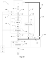
- a system 1 according to a first embodiment comprises a tank 2 and components through which an aqueous liquid can flow, including: at least one purifier 4, 6, 8, 10, at least one minerality modifying device 12, 14 and an outlet 16.
- the system 1 further comprises a circuit 18 fluidically interconnecting components 2, 4, 6, 8, 10, 12, 14, 16.
- the tank 2 is designed to store an aqueous liquid.
- the tank 2 includes an inlet for feeding the tank 2 with aqueous liquid, coming for instance from a tap.
- the inlet may be closed by a cover or any other suitable closing means.
- the tank 2 is preferably a removable element, which may be removed from the system 1 in order to be filled with aqueous liquid away from the system, then put back in the system 1 once it has been filled.
- the outlet 16 is designed to output an aqueous liquid out of the system 1. It is used to dispense an aqueous liquid stored in the tank 2 to a user.
- the outlet 16 may comprise a connector adapted to be releasably and mechanically coupled with an external container, such as a decanter.
- the connector includes a thread adapted to be coupled with a neck of the external container.
- Each purifier of the system 1 is a device configured to purify an aqueous liquid without substantially modifying an amount of minerals of the aqueous liquid.
- the system 1 according to the first embodiment actually comprises several purifiers 4, 6, 8, 10 carrying out this function but having different structures.
- a first purifier 4 of the system 1 is an activated carbon (AC).
- the AC may be configured to remove at least one of the following contaminants from the aqueous liquid: chlorine, at least one disinfection by-product, at least one VOC, at least one organic pollutant, at least one heavy metal.
- the activated carbon is granular (GAC). Alternatively, the activated carbon could be in the form of a felt or pellets or carbon block.
- a second purifier 6 of the system 1 is an ion exchange resin or adsorption media or chelating media (HM-IX).
- the second purifier 6 may be configured to remove at least one of the following contaminants from the aqueous liquid: at least one heavy metal, at least one microbiological contaminant.
- the second purifier 8 is arranged downstream the first purifier 4.
- a third purifier 8 of the system 1 is a microfilter (MF).
- the microfilter is configured to capture particles present in the aqueous liquid and/or released by at least one other purifier, such as the first purifier 4 or the second purifier 6.
- the microfilter MF may be replaced by an ultrafilter (UF).
- the third purifier 8 is arranged downstream the second purifier 6.
- the first purifier 4, the second purifier 6 and the third purifier 8 are arranged in series, in that order.
- a fourth purifier 10 of the system 1 is a UV light configured to irradiate the aqueous liquid with a UV radiation, the UV radiation preferably having a wavelength in the range going from 230 to 290 nanometers.
- the fourth purifier 10 is arranged downstream the third purifier 8.
- any of the purifiers 4, 6, 8, 10 is configured to increase or decrease the conductivity of a reference aqueous liquid by no more than 10 %, the reference aqueous liquid having a conductivity equal to 595 ⁇ S/cm at 25°C before purification.
- all purifiers of the system 1 form together a purification system configured to increase or decrease the conductivity of the reference aqueous liquid as described above by no more than 5 %.
- Each minerality modifying device 12, 14 of the system 1 is configured to modify an amount of minerals of an aqueous liquid.
- the amount of minerals may be modified in two different ways: it may be decreased or increased. Consequently, the conductivity of an aqueous liquid is increased or decreased by each minerality modifying device 12, 14.
- a first minerality modifying device of the system 1 according to the first embodiment is a demineralizer 12.
- the demineralizer 12 is configured to decrease the conductivity of an aqueous liquid.
- the demineralizer 12 may be further configured to decrease the pH of the aqueous liquid.
- an aqueous liquid flowing through the demineralizer 12 is acidified and demineralized.
- the demineralizer 12 may comprise a dealkalization resin arranged to capture calcium and magnesium cations associated with bicarbonate anions, such as a weak acid cation resin (WAC).
- WAC weak acid cation resin
- the dealkalization resin does not require a waste line in contrast with a reverse osmosis (RO) system. Therefore, using the dealkalization resin instead of a reverse osmosis system for demineralizing an aqueous liquid avoids wasting water.
- the demineralizer may comprise a decationization resin or a combination of decationization and deanionization resin, such as strong acid cation (SAC) resin, a weak base anion resin (WBA) or a strong base anion resin (SBA).
- SAC strong acid cation
- WBA weak base anion resin
- SBA strong base anion resin
- SBA strong base anion resin
- the demineralizer 12 may further comprises AC mixed with its resin.
- the purpose of the AC is to protect the resin from chlorine oxidation and to make it free-flowing to easily fill the demineralizer during manufacturing.
- the weight of AC is preferably equal or less than 10% of the weight of the resin.
- a second minerality modifying device of the system 1 is a mineralizer 14.
- the mineralizer 14 is configured to increase the conductivity of an aqueous liquid.
- the mineralizer 14 may be configured to increase the amount of minerals in an aqueous liquid (and its conductivity) only if the aqueous liquid has a pH lower than a threshold.
- the mineralizer 14 may increase the amount of minerals in an aqueous liquid only if the aqueous liquid is acidic (in this case the pH threshold is 7).
- the mineralizer 14 is a solid mineralizer, i.e. stores a solid mineral arranged to dissolve when an aqueous liquid is flowing through the solid mineralizer 14, thereby mineralizing said aqueous liquid. This dissolution occurs only if the aqueous liquid has a pH lower than the above-mentioned threshold. In the case of some solid minerals like MgO, minerals may be released regardless of the pH to create alkaline water.
- the mineralizer 14 is a liquid mineralizer, i.e., stores a liquid mineral concentrate to be mixed with an aqueous liquid.
- the liquid mineral is stored in a cylinder (or barrel) having a nozzle, and a plunger mobile relative to the cylinder.
- the liquid mineral can be expelled by the nozzle by moving the plunger in translation relative to the cylinder.
- An actuator is configured to move the plunger relative to the cylinder.
- the actuator may comprise a stepper motor coupled with a lead screw assembly.
- the liquid mineral concentrate may comprise any inorganic or organic salts. More particularly, the liquid mineral concentrate may comprise a material selected from the group consisting of: sodium or potassium bicarbonate; sodium or potassium carbonate; calcium or magnesium bicarbonate; calcium, magnesium, sodium or potassium chloride; magnesium, sodium or potassium sulfate, and combinations thereof.
- the liquid mineral concentrate may comprise of trace elements beneficial for health such as zinc, selenium, copper and/or vitamins.
- the mineralizer 14 is of solid type, provided that this solid mineralizer can be replaced by a liquid mineralizer.
- the circuit 18 comprises a collection of pipes interconnecting the different components of the system 1.
- the circuit 18 further comprises a pump 20 configured to circulate the aqueous liquid, so that the aqueous liquid can reach and be treated by the different components of the system 1.
- a pump 20 configured to circulate the aqueous liquid, so that the aqueous liquid can reach and be treated by the different components of the system 1.
- the pump 20 is configured to pump liquid from the tank 2 at a constant flowrate.
- the circuit 18 comprises an input line 22, a minerality modifying line 24, a bypass line 26 and an dispense line 28.
- the input line 22 includes the tank 2 and the pump 20.
- the minerality modifying line 24 is arranged downstream the input line 22.
- the minerality modifying line 24 includes the minerality modifying devices 12, 14.
- the bypass line 26 is also arranged downstream the input line 22.
- the bypass line 26 bypasses the minerality modifying devices 12, 14.
- the minerality modifying line 24 and the bypass line 26 are both fluidically connected to the input line 22 at a splitting section 23, and are both fluidically connected to the dispense line 28 at a junction section 27 downstream the splitting section 23.
- the splitting section 23 is located between the purifier 6 and the demineralizer 12, and the junction section 27 is located between the mineralizer 14 and the purifier 8.
- the dispense line 28 is arranged downstream the minerality modifying line 24 and downstream the bypass line 26.
- the dispense line 28 extends from the junction section 27 to the outlet 16.
- the dispense line 28 includes purifier 4, 6, 8, 10.
- the circuit 18 further comprises a valve assembly for selecting one of the minerality modifying line 24 and of the bypass line 26.
- the purpose of the valve assembly is to ensure aqueous liquid coming from the tank 2 and reaching the outlet 16 has flowed through only one of the minerality modifying line 24 and the bypass line 26.
- the valve assembly prevents mixture of aqueous liquid flowing in the minerality modifying line 24 and aqueous liquid flowing in the bypass line 26 upstream the outlet 16.
- the valve assembly comprises a first valve 30 and a second valve 32.
- the first valve 30 is arranged in the minerality modifying line 24, between the splitting section 23 and the junction section 27. More precisely, the second valve 32 is arranged downstream the minerality modifying devices 12, 14 and upstream the junction section 27.
- the first valve 30 is able to be set in two positions:
- the first valve 30 is an active valve. This means that a controller (described later) can set the first valve in the open position or in the closed position by sending appropriate control signals.
- the second valve 32 is arranged in the bypass line 26, between the splitting section 23 and the junction section 27.
- the second valve 32 is able to be set in two positions:
- the second valve 32 is a passive valve.
- the passive valve is not designed to be controlled remotely using control signals.
- the passive valve 32 is configured to open whenever a pressure applied on the passive valve 32 by aqueous liquid coming from the tank 2 exceeds a threshold, and to close otherwise, i.e. whenever a pressure applied on the passive valve by aqueous liquid coming from the tank 2 does not exceed the threshold (in particular, when no pressure is applied on the passive valve by an aqueous liquid coming from the tank 2).
- the second valve 32 is a check valve.
- the second valve prevents aqueous liquid to flow backwards, i.e. towards the tank whatever the pressure applied on the second valve by aqueous liquid in a backward direction (from the outlet 16 towards the tank 2).
- valve 30 in bypass line 26 and valve 32 in minerality modifying line 24 can be inverted (valve 30 in bypass line 26 and valve 32 in minerality modifying line 24).
- the system 1 further comprises a cartridge 40 constituting a removable part which can be removed from the system 1 and replaced by another cartridge in the system 1.
- the cartridge 40 comprises at least one purifier of the system 1 and at least one minerality modifying device of the system 1.
- the cartridge 40 comprises purifiers 4, 6, 8 and the minerality modifying devices 12, 14.
- the cartridge 40 does not comprise the other components of the system 1 described above.
- the cartridge 40 does not include the valve assembly (first valve 30 or second valve 32). This is advantageous in that it makes the cartridge 40 cheaper.
- the cartridge 40 comprises a first line comprising: a first inlet 42 for inputting a first aqueous liquid into the cartridge 40, a purifier configured to purify the first aqueous liquid without substantially modifying an amount of minerals in the first aqueous liquid, a first outlet 44 for outputting the first aqueous liquid outside the cartridge after the first aqueous liquid has been purified by the purifier.
- the first line comprises purifiers 4, 6, 8.
- the first line does not comprise the fourth purifier 10.
- the first outlet 44 is arranged downstream the third purifier 8 and upstream the fourth purifier 10.
- the cartridge could comprise fewer purifiers (two or one among purifiers 4, 6, 8).
- the cartridge 40 further comprises a second line separated from the first line. This means that there is no fluidic connection between the first line and the second line within the cartridge (however, we will see later that such fluidic connection may exist outside the cartridge, in the system 1).
- the second line comprises: a second inlet 46 for inputting a second aqueous liquid into the cartridge 40, a minerality modifying device configured to substantially modify an amount of minerals in the second aqueous liquid, and a second outlet 48 for outputting the aqueous liquid outside the cartridge after the second aqueous liquid has been treated by the minerality modifying device.
- the second line includes the demineralizer 12 and the mineralizer 14.
- a single minerality modifying device could be included in the second line (either the demineralizer 12 or mineralizer 14).
- the first line forms a portion of the dispense line 28, while the second line forms a portion of the minerality modifying line 24.
- the first inlet is arranged downstream the junction section 27.
- the second inlet is arranged downstream the splitting section 23 and upstream the demineralizer 12.
- the second outlet is arranged upstream the junction section 27 and downstream the mineralizer 14.
- the system 1 further comprises a sensing system 50 configured to sense a physical property of an aqueous liquid flowing in the system 1.
- the physical property is related to the amount of minerals of the aqueous liquid. In other words, a change in the amount of minerals in the aqueous liquid will cause a change of the physical property sensed by the sensing system 50.
- the sensing system is able to sense a first value of a physical property of an aqueous liquid as not processed by any of the minerality modifying devices 12, 14 of the system 1, and to sense a second value of the physical property of the aqueous liquid once the aqueous liquid has been processed by the minerality modifying devices 12, 14.
- the first value and the second value of the physical property should be different when the minerality modifying devices work properly.
- the physical property is the conductivity of the aqueous liquid.
- other physical properties may be sensed by the sensing system 50 in replacement of the conductivity, such as a conductance or a resistivity of the aqueous liquid.
- the sensing system is a single sensor arranged downstream the minerality modifying devices 12, 14. More precisely, the sensor 50 is arranged to sense the physical property of aqueous liquid flowing in the dispense line 28.
- the system 1 may further comprises a carbonator 60 configured to carbonate the aqueous liquid reaching the outlet 16.
- the carbonator 60 may comprise a carbonation source storing carbon dioxide and a carbonation valve controlling an amount of carbon dioxide stored in the carbonation tank to be mixed with aqueous liquid dispensed to a user via the outlet 16.
- the carbonator 60 may further comprise a carbon dioxide vent/drain and/or an air vent/drain designed to reduce pressure in a container mechanically coupled with the outlet 16, and corresponding valves for controlling the vents or drains.
- the carbonator 60 may further comprise means for preventing back pressure into upstream parts of the circuit 18. Said means comprise for example a one-way valve between the UV and carbonator 60.
- the carbonator 60 is configured to carbonate the aqueous liquid flowing in the dispense line 28, before reaching the outlet 16.
- the carbonator 60 is configured to carbonate an aqueous liquid stored in a container, after the aqueous liquid has reached the outlet 16. To that end, the carbonator 60 injects carbon dioxide in the dispense line 28 such that the carbon dioxide reaches the outlet 16 then the container in which the aqueous liquid has been collected.
- the system 1 further comprises a user interface 54 allowing a user to interact with the system 1.
- the user interface is able to detect that the user requests some of the aqueous liquid present in the system 1.
- the system 1 further comprises a controller 56 configured to receive data from the sensor 50 and from the user interface 54.
- the controller 56 is further configured to control the valve assembly (active valve 30) and the pump 20.
- the controller 56 comprises or is coupled to a memory able to store data, including data computed by the controller 56 and data sensed by the sensing system 50.
- communication lines between the controller and the sensor 50, the pump 20, and valve 30 are represented by dashed lines.
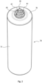
- the cartridge 40 extending along a longitudinal axis X from a first end of the cartridge 40 to a second end of the cartridge 40.
- the first end is a top of the cartridge 40 and the second end is a bottom of the cartridge 40.
- the top is located above the bottom when the cartridge 40 is plugged in the system 1 while the system 1 is in a functional position ready to be used by a user.
- first direction parallel to the longitudinal axis X and running from the top to the bottom
- second direction parallel longitudinal axis X and running from the bottom to the top, opposite to the first direction.
- first direction will be referred to as “downward direction”
- second direction will be referred to as “upward direction”.
- the cartridge 40 comprises a casing 70 for storing various components of the cartridge 40, (including the minerality modifying devices 12, 14 and purifiers 4, 6, 8). Furthermore, the casing 70 defines the first inlet 42, the first outlet 44, the second inlet 46 and the second outlet 48.
- the casing 70 comprises an outer part, the outer part comprising an outer casing 74 and outer cap 76.
- the outer casing 74 delimits an outer cavity 79 for storing components of the cartridge 40 (which will be detailed later) and further delimits an outer top opening forming an access to the outer cavity 79 from outside the outer casing 74.
- the outer casing 74 comprises an outer base wall 78 and an outer lateral wall 80 connected to the outer base wall 78.
- the outer base wall 78 extends in a transversal direction perpendicular to the longitudinal axis X.
- the outer base wall 78 has a substantially circular cross section.
- the outer lateral wall 80 extends in a longitudinal direction parallel to the longitudinal axis X.
- the outer lateral wall 80 extends about the longitudinal axis X.
- the outer lateral wall 80 may be cylindrical.
- the outer base wall 78 and the outer lateral wall 80 delimit together the outer cavity 79. Further, the outer lateral wall 80 delimits the outer top opening. The top opening is opposite to the outer base wall 78 relative to the outer cavity 79.
- the outer cap 76 is configured to be coupled to the outer casing 74 in order to cover the outer top opening thereof.
- the outer cavity 79 extends between the outer base wall 78 and the outer cap 76.
- the outer bottom wall 78 delimits the bottom of the cartridge 40, and the outer cap 76 delimits the top of the cartridge 40.
- the first inlet 42, the first outlet 44, the second inlet 46 and the second outlet 48 are four openings formed in the outer cap 76.
- Said four openings 42, 44, 46, 48 are coaxial and centered on the longitudinal axis X
- the first inlet 42 and the first outlet 44 are arranged such that an aqueous liquid enters in the cartridge 40 through the first inlet 42 by flowing in the downward direction, then exits the cartridge through the first outlet 44 by flowing in the upward direction.
- the second inlet 46 and the second outlet 48 are arranged such that an aqueous liquid enters in the cartridge 40 through the second inlet 46 by flowing in the downward direction, then exits the cartridge through the second outlet 48 by flowing in the upward direction.
- One of said four openings 42, 44, 46, 48 is a central opening, and the three other openings are annular opening extending about the central opening. This arrangement is advantageous, since the cartridge can be more easily plugged in an external system (in particular the system 1).
- the central opening is the second inlet 46.
- the first inlet 42 is an annular opening extending about the second inlet 46.
- the first outlet 44 is another annular opening extending about the second inlet 42.
- the second outlet 48 is a further annular opening extending about the second outlet 44.
- the outer cap 76 further comprises at least one O-ring seal 82 extending about at least one of the four openings 42, 44, 46, 48.
- the embodiment shown in figures 2-6 comprises four O-ring seals 82, respectively extending about the four openings 42, 44, 46, 48.
- the outer cap 76 forms a first connector configured to be mechanically coupled to a second connector of the system 1 (not shown).
- the first connector may be a female connector and the second connector may be a male connector.
- the first line and the second line are fluidically connected to the other components of the system 1.
- the O-rings ensure that the four openings are fluidically separated at the junction formed by the first connector and the second connector.
- the casing 70 further comprises an inner part stored in the outer cavity 79 (delimited by the outer casing 74).
- the inner part can be separated from the outer part by removing the outer cap 76 then moving the inner part out of the outer cavity 79 through the outer top opening. Conversely, the inner part can be inserted in the outer cavity 79 through the outer top opening.
- the inner part comprises an inner casing 84 and an inner cap 86.
- the inner casing 84 delimits an outer cavity 89 for storing components of the cartridge 40 (which will be detailed later) and further delimits an inner top opening forming an access to the inner cavity 89 from outside the inner casing 84.
- the inner casing 84 comprises an inner base wall 88 and an inner lateral wall 90 connected to the inner base wall 88.
- the inner base wall 88 extends in a transversal direction perpendicular to the longitudinal axis X.
- the inner base wall 88 has a substantially circular cross section.
- the inner lateral wall 90 extends in a longitudinal direction parallel to the longitudinal axis X.
- the inner lateral wall 90 extends about the longitudinal axis X.
- the inner lateral wall 90 is cylindrical.
- the inner base wall 88 and the inner lateral wall 90 delimit together the inner cavity 89. Further, the lateral wall delimits the inner top opening. The top opening is opposite to the inner base wall 88 relative to the inner cavity 89.
- the inner cap 86 is configured to be coupled to the inner casing 84 in order to cover the inner top opening thereof.
- the inner cavity 89 extends between the inner base wall 88 and the inner cap 86.
- the inner casing 84 and the inner base wall 88 have an external diameter (measured in a transverse direction perpendicular to the longitudinal axis X) which is smaller than the internal diameter of the outer casing 74. As a consequence, an annular gap is left between the outer lateral wall 80 and the inner lateral wall 90.
- the inner part has a height (measured along the longitudinal axis X when the inner casing 84 and the inner base are coupled together) which is smaller than the height of the outer cavity 79 (measured from the outer base to the outer cap 76).
- the inner part merely occupies a middle portion of the outer cavity 79 and a gap is left between the outer cap 76 and the inner cap 86 at the top of the outer cavity 79.
- a bottom portion of the outer cavity 79 is occupied by other components of the cartridge 40.
- the inner base wall 88 has an inner base opening and the inner cap 86 delimited an inner cap 86 opening.
- the inner base opening and the inner cap 86 opening are coaxial.
- the inner base opening and the inner cap 86 are coaxial and centered on longitudinal axis X.
- the inner cavity 89 delimited by the inner casing 84 is actually a first compartment 89 of the cartridge 40 storing components which are part of the first line of the cartridge 40 described above in relation with figure 1 .
- the lower portion of the outer cavity 79 which extends between the outer base and the inner part, is a second compartment of the cartridge 40 storing components of the second line described above.
- reference numeral 79 of the outer cavity will be used hereinafter to designate the second compartment.
- the first compartment 89 and the second compartment 79 are separated from each other by the inner base wall 88.
- the cartridge 40 further comprises a first pipe 92.
- the first pipe 92 is part of the first line.
- the first pipe 92 is configured to convey a first aqueous liquid from the first inlet 42 to the first compartment 89. More precisely, the first pipe 92 is rectilinear in that it conveys the first aqueous liquid in the downward direction.
- the first pipe 92 extends in the downward direction from the outer cap 76 to the inner base wall 88.
- the first pipe 92 extends through the inner cap 86 opening.
- the first pipe 92 further crosses in the first compartment 89.
- the first pipe 92 extends about the longitudinal axis X.
- the first pipe 92 may be a tube (i.e. a pipe having a circular cross section).
- the first pipe 92 has at least one outlet opening in the first compartment 89. Therefor each outlet is closer to the inner base wall 88 than to the inner cap 86. Any first aqueous liquid coming from the first pipe 92 and entering in the first compartment 89 is constrained to flow in the first compartment 89 in the upward direction towards the inner cap opening.
- the inner cap opening has a diameter which is larger than the external diameter of first pipe 92, such that an annular portion of the inner cap opening is not occupied by the first pipe 92. This annular portion is fluidically connected to the first outlet of the cartridge 40. Thus, a first aqueous liquid flowing in the first compartment 89 in the upward direction then exits the first compartment 89 by flowing through said annular portion of the inner cap opening, before reaching the first outlet 44.
- the cartridge 40 further comprises a second pipe 94.
- the second pipe 94 is part of the second line.
- the second pipe 94 is configured to convey a second aqueous liquid from the second inlet 46 to the second compartment 79.
- the second pipe 94 extends in the downward direction from the outer cap 76 towards the outer base wall 78.
- the second pipe 94 extends through the inner part (through the inner cap 86 opening, through the inner cavity 89 and through the inner base opening).
- the second pipe 94 may contact the outer base wall 78.
- the second pipe 94 extends about the longitudinal axis X.
- the second pipe 94 may be a tube (a pipe having a circular cross section).
- the second pipe 94 has at least one lateral outlet opening in the second compartment 79. The or each lateral outlet is closer to the outer base than to the inner cap 86. Any second aqueous liquid coming from the second pipe 94 and entering in the second compartment 79 is constrained to flow in the second compartment 79 in the upward direction.
- the annular gap left between the outer casing 74 and the inner casing 84 fluidically connects the second compartment 79 to the second outlet of the cartridge 40.
- a second aqueous liquid flowing in the second compartment 79 in the upward direction then flows through said annular gap, before reaching the second outlet 48.
- the second pipe 94 has a length, measured parallel to the longitudinal axis X, which is greater that the length of the first pipe 92.
- the second pipe 94 has a cross section which is smaller than the cross section of the first pipe 92.
- the second pipe 94 is an inner pipe
- the first pipe 92 is an outer pipe extending about the inner pipe.
- the first pipe 92 and the second pipe 94 are coaxial. Arranging the first pipe 92 about the second pipe contributes to make the cartridge 40 compact.
- the following components are stacked in the upward direction, (from the inner base to the inner cap 86):
- Said stacked components extend about the first pipe 92. This arrangement allows a more uniform distribution in the first compartment of a first aqueous liquid supplied by the first pipe 92.
- the separators 96, 98 are perforated plates allowing a good distribution of the water flowing inside the compartment 89.
- the fleece 100 principally keeps the bed in place and can handle bed expansion.
- the following components are stacked in the upward direction, from the outer base wall 78 to the inner base wall 88:
- Said stacked components extend about the second pipe 94. This arrangement allows a more uniform distribution in the second compartment of a second aqueous liquid supplied by the first pipe 94.
- the separators 102, 106 are perforated plates allowing a good distribution of the water flowing inside the second compartment 79.
- the fleece 100 principally keeps the bed in place and can handle bed expansion.
- each purifier 4, 6, 8 is arranged such that a first aqueous liquid has to flow through the purifier in a direction (the upward direction), and each minerality modifying device is arranged such that a second aqueous liquid flows through the minerality modifying device in the very same direction.
- This arrangement is advantageous in that the cartridge 40 can be placed in a position preventing bubbles to be trapped in the purifiers and in the demineralizer at the same time.
- the outer part and the inner part of the casing 70 can be separated from each other.
- the first compartment 89 and the second compartment 79 can be separated. This is advantageous, because when the cartridge 40 is removed from the system 1, it is possible to replace components stored in only one of the two compartments 79, 89.
- This arrangement is environmentally friendly, because it avoids having to throw away a cartridge 40 wherein some components still work.
- a function performed by the circuit 18 is controlling the circulation of an aqueous liquid from the tank 2 to the outlet 16.
- the circuit 18 is configurable in different modes implementing different interconnections between some of the components listed above.
- the circuit 18 is able to be set in an idle mode wherein the aqueous liquid stagnates at least in the tank 2. The aqueous liquid is prevented by the circuit 18 to reach the outlet 16.
- the idle mode is obtained as follows: the active valve 30 is closed and the pump 20 is turned off by the controller 56.
- the circuit 18 is able to be set in a bypass mode wherein the circuit forms a first path fluidically connecting the tank 2 to the outlet 16 and bypassing the minerality modifying devices, and wherein the circuit 18 circulates the aqueous liquid in the first path such that the aqueous liquid is not processed by any minerality modifying device of the system 1 before reaching the outlet 16 (and exiting the system 1).
- the first path is shown in figure 7 by a bold line.
- the bypass mode is obtained as follows: the active valve 30 is closed and the pump 20 is turned on by the controller 56.
- the first path is actually formed by the input line 22, the bypass line 26 and the dispense line 28.
- the first line of the cartridge 40 is included in the first path.
- the circuit 18 When set in the bypass mode, the circuit 18 circulates some of the aqueous liquid stored in the tank 2 to the outlet 16 at a first flowrate.
- the aqueous liquid flows in the input line 22, then in the bypass line 26, then in the dispense line 28.
- the check valve 32 opens because of the pressure applied thereon by the aqueous liquid. This is due to the fact that the minerality modifying line 24 is closed by the active valve 30.
- the first flowrate is constant in the first path.
- the aqueous liquid flows through the following components, in that order before reaching the outlet 16: the first line of the cartridge (the first inlet 42, the first purifier 4, the second purifier 6, the third purifier 8, the first outlet 44), the fourth purifier 10, and the carbonator 60.
- the aqueous liquid bypasses the second line of the cartridge (the minerality modifying devices 12, 14); therefore, the minerality of the aqueous liquid is not substantially modified by the system 1.
- the aqueous liquid passes through the first line of the cartridge as follows.
- the aqueous liquid enters the cartridge by the first inlet 42, then flows in the first pipe 92 in the downward direction, then reaches the first compartment 89. Then, the aqueous flows in the first compartment 89 in the upward direction.
- the aqueous liquid is treated by the first purifier 4, then by the second purifier 6, then by the third purifier 8. Then, the aqueous liquid flows through the annular gap left between the inner casing 84 and the outer casing 74, then reaches the first outlet 44 of the cartridge, as shown in figure 5 .
- the circuit 18 is able to be set in a processing mode wherein the circuit forms a second path fluidically connecting the tank 2 to the outlet 16 and passing through the minerality modifying devices 12, 14, and wherein the circuit 18 circulates the aqueous liquid in the second path such that the aqueous liquid is processed by the minerality modifying devices 12, 14 before reaching the outlet 16.
- the second path is shown in figure 8 by a bold line.
- the processing mode is obtained as follows the active valve 30 is open and the pump 20 is turned on by the controller 56.
- the second path closed loop is actually formed by the input line 22, the minerality modifying line 24 and the dispense line 28.
- the aqueous liquid flows through the following components, in that order before reaching the outlet 16: the second line of the cartridge 40, the junction section 27, the first line of the cartridge 40 (the first purifier 4, the second purifier 6, the third purifier 8), the fourth purifier 10, and the carbonator 60.
- the minerality modifying devices 12, 14 the minerality of the aqueous liquid is substantially modified.
- the conductivity of the aqueous liquid is substantially modified.
- the amount of minerals of the aqueous liquid flowing in the second path is decreased by the demineralizer 12, then increased by the mineralizer 14.
- the aqueous liquid passes through the first line of the cartridge 40 like in the bypass mode.
- the aqueous liquid passes through the second line of the cartridge 40 as follows.
- the aqueous liquid passes through the second inlet 46, then flows in the second pipe 94 in the downward direction, then reaches the second compartment 79. Then, the aqueous flows in the second compartment 79 in the upward direction.
- the aqueous liquid is treated by the demineralizer 12, then treated by the mineralizer 14. Then, the aqueous liquid flows through the annular portion of the inner cap 86 opening left by the second pipe 94, then reaches the second outlet 48 of the cartridge 40.
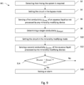
- a rinsing method M1 performed by the system 1 comprises the following steps.
- the tank 2 has been filled with a volume of aqueous liquid, for example 2 L of tap water.
- a container such as a decanter has been placed by a user at the outlet 16 (as shown in figure 1 ).
- the controller 56 detects that the system 1 has to be rinsed.
- the controller 56 may detect at least one of the following events: the system 1 has been powered on, a new cartridge 40 has been installed in the system 1, the tank 2 has been removed then placed back in the system 1, and/or a user has requested a rinsing by means of the user interface.
- a step S4 the controller 56 sets the circuit 18 in the bypass mode by sending appropriate commands to the pump 20 and to the valve assembly (active valve 30).
- the controller 56 causes the pump 20 to circulate in the first path (shown in figure 7 ) a small volume of the aqueous liquid stored in the tank 2, for instance 0.1 L.
- the sensing system 50 senses a first conductivity ⁇ feed of the aqueous liquid flowing in the first path (step S6).
- the first conductivity is therefore the conductivity of the aqueous liquid as not processed by any of the minerality modifying devices 12, 14 of the system 1.
- the sensor 50 sends the first conductivity to the controller 56.
- step S8 the controller 56 determines a target conductivity ⁇ target .
- the controller 56 computes the target conductivity ⁇ target at step S8 from the first conductivity ⁇ feed .
- the target conductivity may be computed as the first conductivity ⁇ feed multiplied by a predefined coefficient lower than 1. For example, when this predefined coefficient is 0.5, the target conductivity ⁇ target is 50% of the first conductivity ⁇ feed .
- the target conductivity ⁇ target is known in advance and stored in a memory of the system 1. In this case the controller 56 merely loads the target conductivity ⁇ target from the memory.
- the controller 56 sets the circuit 18 in the processing mode by sending appropriate commands to the pump 20 and to the valve assembly.
- the controller 56 causes the pump 20 to circulate in the second path another volume of the aqueous liquid stored in the tank 2. This volume of aqueous liquid is adapted to ensure that the minerality modifying devices 12, 14 are flushed.
- the sensing system 50 senses a second conductivity ⁇ outlet of the aqueous liquid flowing in second first path (step S12).
- the second conductivity ⁇ outlet is the conductivity of the aqueous liquid as processed by the minerality modifying devices 12, 14 of the system 1.
- the sensor 50 sends the second conductivity to the controller 56.
- the sensing system 50 may actually sense a sequence of conductivity values of the aqueous liquid flowing in the second path, and select a value of the sequence as the second conductivity value only if said value is close enough to a preceding value or to a next value of the sequence. In other words, the sensing system 50 waits for the conductivity of the aqueous liquid flowing in the second path to become stable. The sensor 50 sends the second conductivity to the controller 56.
- a step S14 the controller 56 compares the first conductivity and the second conductivity. If a gap between the first conductivity and the second conductivity is below a predefined threshold S, then the controller 56 raises an alarm. In fact, this situation reveals that the minerality modifying devices 12, 14 are not working properly. The alarm may be sent to the user interface, such that the user is notified. The user may be invited to replace the cartridge 40 installed in the system 1 by a brand new one, by means of an appropriate message displayed by the user interface.
- a method M2 of dispensing an aqueous liquid to a user comprises the following steps performed by system 1.
- the tank 2 has been filled with a volume of aqueous liquid, for example 2 L of tap water.
- a container such as a decanter has been placed by a user downstream the outlet 16 (as shown in figure 1 ).
- the controller 56 detects that a predefined volume of the aqueous liquid stored in the tank has to be dispensed to a user.
- the controller 56 may detect that a user has requested this by means of the user interface 54.
- the predefined volume may be selected by the user or set by the controller 56.
- Step S24 the controller 56 sets the circuit 18 in the bypass mode by sending appropriate commands to the pump 20 and to the valve assembly (active valve 30).
- Step S24 is similar to step S4.
- a small amount of the aqueous liquid stored in the tank 2 flows in the first path, reaches the outlet 16 and is received by the container. This aqueous liquid has not been processed by any of the minerality modifying devices 12, 14 since it does not come from the minerality modifying line 24.
- Step S26 is similar to step S6.
- the conductivity value sensed at step S26 is saved in the memory of the controller 56 in replacement of any prior value for ⁇ feed (in particular any value obtained at step S6).
- a step S28 the controller 56 computes a bypass ratio b from the first conductivity ⁇ feed and the second conductivity ⁇ outlet which are stored in the memory thereof.
- the bypass ratio b is saved in the memory of the controller 56.
- Step S30 the controller 56 sets the circuit 18 in the processing mode by sending appropriate commands to the pump 20 and to the valve assembly. Step S30 is similar to step S10.
- the sensing system 50 senses a second conductivity ⁇ outlet of the aqueous liquid flowing in second path (step S32).
- the second conductivity ⁇ outlet is the conductivity of the aqueous liquid as processed by the minerality modifying devices 12, 14 of the system 1.
- the sensing system 50 sends the second conductivity to the controller 56, and replaces any prior value of ⁇ outlet in the memory of the controller 56. In other words, the conductivity ⁇ outlet in the memory is updated with the value sensed at step S32.
- the controller 56 may cause the circuit 18 to alternate between the bypass mode and the processing mode until the predefined volume of aqueous liquid reaches the outlet and is received in the container.
- the controller 56 takes into account the volumes of aqueous liquid already delivered at steps S22 and S30. Once this volume has been delivered, the controller 56 sets the circuit 18 in the idle mode.
- the predefined volume reaching the outlet 16 during steps S22, S30 and S34 consists of:
- controller 56 causes the circuit 18 to alternate between the bypass mode and the processing mode such that the predefined volume of the aqueous liquid which is delivered and received in the contained has an average conductivity corresponding to the target conductivity.
- the controller 56 ensures that the first volume is proportional to b (the first volume includes the volume delivered at step S22), and that the second volume is proportional to 1-b (the second volume includes the volume delivered at step S30).
- controller 56 computes the following durations before step S34:
- the first duration and the second duration may be computed by the controller 56 from the following data: the bypass ratio b, the first flowrate (flowrate of the aqueous liquid flowing in the first path while the circuit is in the bypass mode) and the second flowrate (flowrate of the aqueous liquid flowing in the second path while the circuit is set in the processing mode).
- the first flowrate and the second flowrate are equal, the first duration is proportional to b, and the second duration is proportional to 1-b.
- circuit spends time in the bypass mode at step S22, and spends time in the processing mode at step S30.
- the controller 56 maintains the circuit in the bypass for a duration equal to the first duration minus the duration spent in the bypass mode at step S22, and maintains the circuit 18 in the processing mode for a duration equal to the second duration minus the duration spent in the processing mode at step S30.
- the controller 56 may sense the first volume and the second volume using a sensor included in the system 1, for example a flowrate sensor.
- the controller 56 keeps the circuit in the bypass mode until it is sensed that the volume of the first volume has reached the outlet 16, and keeps the circuit in the processing mode until it is sensed that the volume of the second volume has reached the outlet 16.
- the first volume is divided into N first sub-volumes and the second volume is divided into M second sub-volumes, the N first sub-volumes and the M second sub-volumes being delivered by the circuit alternately during distinct time intervals.
- M or N is at least equal to 2, and M and N are equal or differ by one.
- the controller 56 switches the circuit 18 multiple times between the bypass mode and the processing mode.
- the circuit 18 is selectively set by the controller 56 in the processing mode and in the bypass mode multiple times on the basis of the first conductivity, the second conductivity and a target conductivity during method M2, such that the predefined volume of the aqueous liquid stored in the tank reaches the outlet 16, and such that the predefined volume has an average conductivity corresponding to the target conductivity.
- the controller 56 preferably alternates between said modes using a frequency adapted to ensure that a previous volume is flushed, thereby allowing the conductivity to be sensed to be stable.
- the method M2 further comprises a step S36 wherein the controller compares the computed bypass ratio b with a predefined threshold Bmin. If the bypass ratio b is below the predefined threshold Bmin, then the controller may raise an alarm (step S38). Of course, steps S36, S38 may be performed right after the computation of the bypass ratio at step S28.
- the method M2 is particularly advantageous in that it ensures that the aqueous liquid dispensed to the user has a desired taste (reflected by the target conductivity) during the entire lifetime of the minerality modifying devices 12, 14, especially the demineralizer 12.
- a resin used by the demineralizer 12 can get exhausted, causing the second conductivity to vary over time.
- the controller 56 changes the mode of the circuit only once.
- step S34 may not be performed.
- This strategy is illustrated in figure 11b .
- the first volume (aqueous liquid not processed by any minerality modifying device of the system 1) and the second volume (aqueous liquid processed by the minerality modifying devices of the system 1) are represented by two different layers in the container, with the second volume above the first part.
- the circuit 18 is selectively set by the controller 56 once in the processing mode and once in the bypass mode on the basis of the first conductivity, the second conductivity and a target conductivity, such that the predefined volume of the aqueous liquid stored in the tank reaches the outlet 16, and such that the predefined volume has an average conductivity corresponding to the target conductivity.
- the methods M1, M2 described above are not limited to embodiments wherein conductivities are sensed by the sensing system 50. Said methods can be generalized to any of the physical properties discussed above related to the amount of minerals in the aqueous liquid.
- a system 1' according to a second embodiment is shown in figure 12 .
- the system 1' has numerous components in common with system 1 (designated by the same reference numerals), including components 2, 4, 6, 8, 10, 12, 14, 16, 20, 50, 54, 56, 60.
- the system 1 further comprises a circuit 18' fluidically interconnecting 2, 4, 6, 8, 10, 12, 14, 16, 20, 50, 60.
- the mineralizer 14 can either be a solid mineralizer or a liquid mineralizer.
- the mineralizer 14 is of liquid type, provided that this liquid mineralizer can be replaced by a solid mineralizer.
- the circuit 18' differs from the circuit 18 by its working modes and the way it interconnects the components.
- the circuit 18' comprises pipes defining a main line 22'.
- the main line 22' includes the tank 2, the first purifier 4, the second purifier 6, the third purifier 8, the mineralizer 14, the fourth purifier 10 arranged in series, in that order. Fewer purifiers may be included in the main line 22, and their order may be different. Purifiers 4 and 6 can also be mixed.
- the pump 20 is included in the main line 22, for example between the tank 2 and the first purifier 4 as shown in figure 1 .
- the circuit 18' further defines two return lines 24', 26'.
- the return lines 24', 26' include a minerality modifying line 24' and a bypass line 26'.
- the tank 2 is arranged in output of each of the two return lines 24', 26'.
- the minerality modifying line 24' includes the demineralizer 12.
- the circuit 18' further defines a dispense line 28'.
- the dispense line 28' includes the carbonator 60 and the outlet 16 of the system 1.
- the circuit 18' further comprises a dispense valve 30' between the main line 22' and the dispense line 28'.
- the dispense valve 30' is configurable into an open position wherein the main line 22' and the dispense line 28' are fluidically connected by the dispense valve 30', thereby allowing an aqueous liquid flowing in the main line 22' to reach the outlet 16.
- the dispense valve 30' is also configurable into a closed position which fluidically isolates the dispense line 28' from the main line 22, thereby preventing an aqueous liquid flowing in the main line 22' from reaching the outlet 16.
- the dispense valve 30' may for instance be a solenoid valve.
- the circuit 18' further comprises a valve assembly 31' for selectively redirecting an aqueous liquid flowing in the main line 22' to only one of the two return lines 26, 28 at a time.
- valve assembly 31' is configurable into a first position wherein the valve assembly 31' fluidically connects the main line 22' to the minerality modifying line 24', thereby redirects the aqueous liquid in the minerality modifying line 24'.
- the valve assembly 31' further disconnects the bypass line 26' and the output line 28' from the main line 22'.
- 100% of the aqueous liquid coming from the main line 22' and reaching the valve assembly 31' is redirected in the minerality modifying line 24' whenever the valve assembly 31' is set in the first position.
- valve assembly 31' is configurable into a second position wherein the valve assembly 31' fluidically connects the main line 22' to the bypass line 26' and disconnects the minerality modifying line 24' and the output line 28' from the main line 22'.
- 100% of the aqueous liquid coming from the main line 22' and reaching the valve assembly 31' is redirected in the bypass line 26' whenever the valve assembly 31' is set in the second position.
- the valve assembly 31' is configurable into a third position wherein the valve assembly 31' prevents an aqueous liquid contained in the main line 22' from reaching the return lines 24', 26'.
- the valve assembly 31' may comprise two valves 34', 36': a first valve 34' controlling access to the mineral modifying line 24', and a second valve 36' controlling access to the bypass line 26'.
- Each valve may be for instance a solenoid valve.
- the first position, the second position and the third position of the valve assembly 31' can be obtained by opening or closing the two valves appropriately.
- the circuit 18' may further comprise a vent or a drain configured to reduce a pressure in the main line 22', and a pressure relief valve controlling said pressure reduction.
- the system 1' further comprises a cartridge 40' constituting a removable part which can be removed from the system 1 and replaced by another cartridge in the system 1.
- the cartridge 40' comprises at least one purifier of the system 1 and at least one minerality modifying device.
- the cartridge 40' comprises a first line comprising: a first inlet 42' for inputting a first aqueous liquid into the cartridge 40', a purifier configured to purify the first aqueous liquid without substantially modifying an amount of minerals in the first aqueous liquid, a first outlet 44' for outputting the first aqueous liquid outside the cartridge after the first aqueous liquid has been purified by the purifier.
- the first line comprises purifiers 4, 6, 8, and the mineralizer 14.
- the first line does not comprise the fourth purifier 10.
- the first outlet 48 is arranged downstream the third purifier 8 and upstream the fourth purifier 10.
- the first line could comprise fewer purifiers (two or one among purifiers 4, 6, 8).
- the mineralizer 14 could be located outside the cartridge 40', thus not be present in cartridge 40'.
- the cartridge 40' further comprises a second line separated from the first line. This means that there is no fluidic connection between the first line and the second line within the cartridge 40' (however, we will see later that such fluidic connection may exist outside the cartridge in the system 1').
- the second line comprises: a second inlet 46' for inputting a second aqueous liquid into the cartridge 40, a minerality modifying device configured to substantially modify an amount of minerals in the second aqueous liquid, and a second outlet 48' for outputting the second aqueous liquid outside the cartridge after the second aqueous liquid has been treated by the minerality modifying device.
- the second line of the cartridge 40' includes the demineralizer 12.
- the first line forms a portion of the main line 22', while the second line forms a portion of the minerality modifying line 28'.
- the first inlet 42' is arranged downstream the pump 20.
- the second inlet 46' is arranged downstream the valve assembly 31' and upstream the demineralizer 12.
- the second outlet is arranged upstream the tank 2 and downstream the mineralizer 14.
- the sensing system 50 is arranged in the main line, between the tank 2 and the first purifier 4.
- the temperature sensor 58 is arranged as well in the main line 22.
- the controller 56 configured to receive data from the sensor 50 and from the user interface 54.
- the controller 56 is further configured to control the valve assembly 31', the dispense valve, the pump 20 and the actuator of mineralizer 14, if said mineralizer is of the liquid type described above.
- the controller 56 comprises or is coupled to a memory able to store data, including data computed by the controller 56 and data sensed by the sensing system 50.
- communication lines between the controller and the sensor 50, the pump 20, and valves 30', 31' are represented by dashed lines.
- the cartridge 40' extending along a longitudinal axis X' from a first end of the cartridge to a second end of the cartridge.
- the first end is a top of the cartridge and the second end is a bottom of the cartridge.
- the top is located above the bottom when the cartridge 40' is plugged in the system 1' while the system 1 is in a functional position ready to be used by a user.
- first direction parallel to the longitudinal axis X' and running from the top to the bottom
- second direction parallel longitudinal axis X' and running from the bottom to the top, opposite to the first direction.
- first direction will be referred to as “downward direction”
- second direction will be referred to as “upward direction”.
- the cartridge 40' comprises a casing 70' for storing various components of the cartridge, (including the minerality modifying devices 12, 14 and purifiers 4, 6, 8). Furthermore, the casing 70' defines the first inlet 42', the first outlet 44', the second inlet 46' and the second outlet 48'.
- the casing 70' comprise different parts, which are releasably coupled to each other and which can therefore be separated from each other.
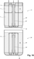
- the casing 70 comprises a first part 74' (or first casing 74') delimiting a first compartment 79' for storing components of the cartridge 40' (which will be detailed later).
- the first casing 74' has a first top opening forming an access to the first compartment 79' from outside the first casing 74'.
- the first casing 74' comprises a first base wall 78' and a first lateral wall 80' connected to the first base wall 78'.
- the first base wall 78' extends in a transversal direction perpendicular to the longitudinal axis X'.
- the first base wall 78' has a substantially circular cross section.
- the first lateral wall 80' extends in a longitudinal direction parallel to the longitudinal axis X.
- the first lateral wall 80' extends about the longitudinal axis X'.
- the first lateral wall 80' may be cylindrical.
- the first base wall 78' and the first lateral wall 80' delimit together the first compartment 79'. Further, the first lateral wall 80' delimits the first top opening.
- the first top opening is opposite to the first base wall 78' relative to the first compartment 79'.
- the casing 70' further comprises a second part 84' (or second casing 84') delimiting a second compartment 89'.
- the second casing 84' has a second top opening forming an access to the second compartment from outside the second casing 84'.
- the second casing 84' comprises a second base wall 88' and a second lateral wall 90' connected to the second base wall 88'.
- the second base wall 88' extends in a transversal direction perpendicular to the longitudinal axis X'.
- the second base wall 88' has a substantially circular cross section.
- the second lateral wall 90' extends in a longitudinal direction parallel to the longitudinal axis X'.
- the second lateral wall 90' extends about the longitudinal axis X'.
- the second lateral wall 90' is cylindrical.
- the second base wall 88' and the second lateral wall 90' delimit together the second compartment 89'. Further, the lateral wall delimits the second top opening.
- the second top opening is opposite to the second base wall 88' relative to the second compartment 89'.
- the second casing 84' is configured to be coupled to the first casing 74', such that the first base wall 78' covers the second top opening.
- the second compartment 89' extends between the second base wall 88' and the first base wall 78'.
- Two threads can be used as means for coupling the second casing 84' to the first casing 74'.
- the first casing 74' comprises a first thread extending on the first lateral wall 80'
- the second casing 84' comprises a second thread extending on the second lateral wall 90'.
- the threads are engaged with each other, thereby coupling the second casing 84' with the first casing 74'.
- Both casings 74' et 76' can be separated by rotating one of the two casings relative to the other casing about axis X', thereby disengaging the two threads.
- Alternate or additional coupling means may be used for releasably coupling casing 74' and 84'.
- the first compartment 89' and the second compartment 79' are separated from each other by the first base wall 78'.
- the second casing 84' includes the second inlet 46' and the second outlet 48'. More precisely, the second inlet 46' and the second outlet 48' are formed in two protrusions extending from the second lateral wall.
- the second inlet 46' and the second outlet 48' are arranged so as to be parallel, such that an aqueous liquid enters in the cartridge 40' through the second inlet by flowing in a first transversal direction, then exits the cartridge through the second outlet 48' by flowing in a second transversal direction opposite to the first transversal direction (both transversal directions being perpendicular to the longitudinal axis X). This arrangement makes the connection of the cartridge to the system easier.
- the casing 70 further comprises a third part 71' (or third casing 71 ').
- the third casing 71' comprises a third base wall 73'.
- the third base wall 73' includes a central opening centered on longitudinal axis X, and at least one further opening with may be off-center with respect to the longitudinal access X or annular.
- the third casing 71' is configured to be coupled to the first casing 74' in order to cover the first top opening thereof.
- the outer cap 76' is coupled to the first casing 74', the first compartment 79' extends between the first base wall 78' and the third casing 71'.
- Two threads can be used as means for coupling the third casing 71' to the first casing 74'.
- the first casing 74' comprises a third thread extending on the first lateral wall 80'
- the third casing 71' comprises a fourth thread extending on a lateral wall thereof.
- the threads are engaged with each other, thereby coupling the third casing 71' with the first casing 74'.
- Both casings 74' et 71' can be separated by rotating one of the two casings relative to the other casing about axis X', thereby disengaging the two threads.
- Alternate or additional coupling means may be used for releasably coupling casing 74' and 71'.
- the third casing 71' includes the first inlet 42' and the first outlet 44'. More precisely, the first inlet 42' and the second outlet 44' are formed in a lateral wall of the third part 71'. The first inlet 42' and the first outlet 44' are oriented parallel, such that an aqueous liquid enters in the cartridge 40' through the first inlet 42' by flowing in the first transversal direction already discussed above, then exits the cartridge through the second outlet 44' by flowing in the second transversal direction opposite to the first transversal direction already discussed above.
- the third part 71' comprise a first passageway which fluidically connects the central opening to the first inlet 42', and a second passageway which fluidically connects the at least one further opening to the first outlet 44'. Both passageways are part of the first line.
- the third casing 71' comprises a mixing chamber 75'.
- the mixing chamber 75' is part of the first line as well.
- the mixing chamber 75' is actually arranged downstream the first compartment 79' and upstream the first outlet 44'. In other words, any aqueous liquid flowing in the first compartment 79' then flows through the mixing chamber 75' before reaching the first outlet 44'.
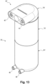
- the third casing 71' comprises two connectors able to be coupled to two further connectors of the system 1'. As shown in figure 13 , the two connectors of the third casing are female connectors. One of said connectors comprising a groove extending about the first inlet 42' and the other connector comprises a groove extending about the first outlet 44'.
- the third casing 71' further includes the mineralizer 14, which is of the liquid type.
- the liquid mineralizer 14 comprises a cylinder 77' (or barrel) storing a liquid mineral concentrate C to be mixed with an aqueous liquid flowing in the second line of the cartridge 40'.
- the cylinder 77' has a nozzle 81' opening in the mixing chamber 75'.
- the third casing 71' delimits an access to the cylinder 77' from outside the cartridge 40'.
- the mineralizer 14 comprises a gasket 83' arranged in the cylinder 77', and mobile in translation relative to the cylinder 77'.
- the liquid mineral concentrate C is stored in a portion of the cylinder 77' extending between the gasket 83' and the nozzle 81'.
- the gasket seals the cylinder 77', thereby preventing the liquid concentrate to exit the cylinder.
- the liquid mineral can be expelled by the nozzle 81' by moving the gasket 83' in translation relative to the cylinder towards the nozzle 81'.
- a plunger of can be inserted in the cylinder by the access above mentioned and press on the gasket 83'.
- the gasket 83' remains stationary with respect to the cylinder 77', the liquid concentrate C stored in the cylinder 77' does to pass through the nozzle 81'.
- said liquid concentrate C cannot be mixed with any aqueous liquid present in the mixing chamber 75'.
- the gasket 83' is configured to remain stationary if no pressure is applied thereon.
- the cartridge 40' does not include the plunger or the actuator for moving the plunger.
- the plunger and the actuator are further parts of the system 1'. This makes the cartridge 40' cheaper.
- the cartridge 40' further comprises a first pipe 92'.
- the first pipe 92' is part of the first line.
- the first pipe 92' is configured to convey a first aqueous liquid from the central opening of the third part 71' to the first compartment 79'. More precisely, the first pipe 92' is rectilinear in that it conveys the first aqueous liquid in the downward direction.
- the first pipe 92' extends in the first compartment 79' from the third base wall 73' to the first base wall 78'.
- the first pipe 92' extends about the longitudinal axis X'.
- the first pipe 92' may be a tube (i.e. a pipe having a circular cross section).
- the first pipe 92' has at least one lateral outlet opening in the first compartment 89'. The or each lateral outlet is closer to the first base wall 78' than to the third base wall 73'. Any first aqueous liquid coming from the first pipe 92' and entering in the first compartment 79' is constrained to flow in the first compartment 79' in the upward direction towards the mixing chamber 75'.
- the cartridge 40' further comprises a second pipe 94'.
- the second pipe 94' is part of the second line.
- the second pipe 94' is configured to convey a second aqueous liquid from the second compartment 89' towards the second outlet 48'.
- the second pipe 94' extends in the second compartment between the first base wall 78' and the second base wall 88'.
- the second pipe 94' may contact the first base wall 78'.
- the second pipe 94' extends about the longitudinal axis X'.
- the second pipe 94' may be a tube (a pipe having a circular cross section).
- the second pipe 94' has at least one lateral inlet opening in the second compartment 89'.
- the or each lateral inlet is closer to the first base wall 78 than to the second base wall 88. Any second aqueous liquid coming from the second inlet 46 is constrained to flow in the second compartment 89' in the upward direction second pipe 94', then to enter in the second pipe 94', then to flow in the second pipe 94' in the downward direction before reaching the second outlet 48'.
- the first pipe 92' and the second pipe 94' are coaxial.
- the pipes 92' and 94' are separated by the first base wall 78'.
- the first compartment 79' of the cartridge 40' stores the same components as the first compartment 89 of the cartridge 40 described above.
- the following components are stacked in the upward direction (from the first base wall 78' to the third base wall 73'):
- Said stacked components extend about the first pipe 92'. This arrangement allows a more uniform distribution in the first compartment of a first aqueous liquid supplied by the first pipe 92'.
- the second compartment 89' of the cartridge 40' stores the demineralizer 12. No other component is present in the second compartment.
- each purifier 4, 6, 8 is arranged such that a first aqueous liquid has to flow through the purifier in a direction (the upward direction), and the demineralizer 12 is arranged such that a second aqueous liquid flows through the minerality modifying device in the very same direction.
- This arrangement is advantageous in that the cartridge can be placed in a position preventing bubbles to be trapped in the purifiers and in the demineralizer at the same time.
- the first part, the second part and the third part of the casing 70' can be separated from each other. This arrangement is environmentally friendly, because it avoids having to throw away a cartridge wherein some components still work.
- a function of the circuit 18' is that of fluidically interconnecting the tank 2, at least one purifier, at least one minerality modifying device and an outlet 16.
- the circuit 18' is configurable in different modes implementing different interconnections between some of the components listed above.
- the circuit 18' is configurable into an idle mode wherein the aqueous liquid stagnates at least in the tank 2.
- the idle mode is obtained as follows by the controller 56: the dispense valve 30' is closed, the carbonation valve is closed, the pump 20 is turned off, and the motor coupled to the mineralizer 14 is turned off.
- the circuit 18' is configurable in a purification mode wherein the circuit 18' forms a first closed loop fluidically connecting at least one purifier to the tank 2, circulates the aqueous liquid in the first closed loop such that the aqueous liquid flows through the purifier and through the tank 2, and prevents the aqueous liquid from reaching the outlet 16 and from substantially modifying the amount of minerals of the aqueous liquid.
- the circuit 18' when the circuit 18' is configured in the purification mode, the aqueous liquid flowing in the first closed loop is prevented from reaching the demineralizer, and prevented from being mineralized by the mineralizer.
- the purification mode is obtained as follows by means of the controller 56: the dispense valve 30' is closed, the valve assembly 31' is set in the second position (interconnecting the main line 22' and the bypass line 26'), the carbonator is turned off, the pump 20 is turned on. Furthermore, the motor coupled to the mineralizer 14 is turned off.
- the first closed loop is actually formed by the tank 2, the main line 22', the valve assembly 31' and the bypass line 26'.
- the first line of the cartridge 40' forms a portion of the first closed loop.
- the second line is not part of the first closed loop.
- the aqueous liquid stored in the tank 2 flows through the main line 22' including the first line of the cartridge 40, then is redirected to the tank 2 by means of the valve assembly 31' and the bypass line 26'.
- the aqueous liquid is purified, but the amount of minerals of the aqueous liquid does not substantially change.
- the aqueous liquid flows through the first line of the cartridge 40' as follows.
- the aqueous liquid enters the cartridge 40' by the first inlet 42', then flows through the first passageway formed in the third casing 71' then flows in the first pipe 92' in the downward direction, then reaches the first compartment 79'. Then, the aqueous flows in the first compartment 79' in the upward direction.
- the aqueous liquid is treated by the first purifier 4, then by the second purifier 6, then by the third purifier 8. Then, the aqueous liquid flows through the mixing chamber 75', then reaches the first outlet 44' of the cartridge. Since the motor coupled to the mineralizer is turned off, the gasket 83' remains stationary in the cylinder 77'. This prevents the liquid mineralizing concentrate C stored in the cylinder 77' from reaching chamber 75'.
- the circuit 18' is configurable in a minerality modifying mode wherein the circuit 18' forms a second closed loop fluidically connecting a minerality modifying device of the system 1' to the tank 2, circulates the aqueous in the second closed loop such that the aqueous liquid flows through (and is treated by) the minerality modifying device and through the tank 2, and prevents the aqueous liquid from reaching the outlet 16.
- the minerality modifying mode is a demineralization mode, which means that the minerality modifying device included in the second closed loop is the demineralizer 12. Besides, in the demineralization mode, the aqueous liquid is not mineralized by the mineralizer 14.
- the purification mode is obtained as follows by means of the controller 56: the dispense valve 30' is closed, the valve assembly 31' is set in the first position (interconnecting the main line 22' and the minerality modifying line 24'), the carbonation valve is closed, the pump 20 is turned on, the motor of the mineralizer 14 is turned off.
- the second closed loop is actually formed by the tank 2, the main line 22', the valve assembly 31' and the minerality modifying line 24'. Both the first line and the second line of the cartridge 40 are part of the second closed loop.
- the aqueous liquid stored in the tank 2 flows through the different purifiers arranged in the main line 22', then is redirected to the demineralizer 12 then to the tank 2 by means of the valve assembly 31' and the minerality modifying line 24'.
- the aqueous liquid is not only purified but its amount of minerals of decreased by the demineralizer 12.
- the aqueous liquid flows through the first line of the cartridge 40' like in the purification mode.
- the aqueous liquid flows through the second line of the cartridge 40' as follows.
- the aqueous liquid enters the cartridge 40' by the second inlet 46', then reaches the second compartment 89'.
- the aqueous flows in the second compartment 89' in the upward direction.
- the aqueous liquid is demineralized by the demineralizer 12 stored in the second compartment 89'.
- the aqueous liquid enters the second pipe 94' then flowing through the second pipe 94' in the downward direction before reaching the second outlet 48'.
- the circuit 18' is further configurable into a dispensing mode wherein the circuit 18' forms a path fluidically connecting the tank 2 to the outlet 16, such that the aqueous liquid flows from the tank 2 to the outlet 16.
- the dispensing mode is obtained as follows: the dispense valve 30' is open, the valve assembly 31' is set in the third position (wherein the valve assembly 31' prevents an aqueous liquid contained in the main line 22' from reaching the return lines), the pump 20 is turned on.
- the motor of the mineralizer 14 may be turned on or off, depending on a target minerality to be obtained.
- the path is actually formed by the main line 22', the dispense valve 30' and the dispense line 28'.
- the aqueous liquid stored in the tank 2 flows through the different purifiers arranged in the main line 22' and is optionally mixed with the liquid mineral provided by the mineralizer 14 before reaching the outlet 16.
- the aqueous liquid is purified again and its amount of minerals is optionally increased by the mineralizer 14 before being dispensed to a user.
- the aqueous liquid may also be carbonated using the carbonation system 60.
- the aqueous liquid flows through the first line of the cartridge 40' like in the purification mode if no mineralization is need. If the controller 56 decides to mineralize the aqueous liquid, a plunger is moved in the cylinder 77' so as to press on the gasket 83'. This causes the gasket 83' to be moved towards the nozzle 81', and some of the liquid mineral concentrate C to be expelled in the mixing chamber 75'. The aqueous liquid flowing in the mixing chamber 75' is therefore mixed with the liquid mineral concentrate C.
- the controller 56 of the system 1' is in charge of switching the circuit 18' between the modes described above, by controlling the valves, the pump 20 and or the motor of the mineralizer 14 (if said motor is present).
- the controller 56 is configured to switch the circuit into the above-mentioned modes by applying the rules explained in the sequence below.
- the controller 56 is configured to switch the circuit 18' from the minerality modifying mode to the purification mode once a parameter sensed by the sensing system 50 (for example conductivity) has reached a target value.
- the controller 56 is configured to switch the circuit 18' from the minerality modifying mode to the purification mode once it detects that circuit 18' has been operating in the minerality modifying mode for a maximum duration.
- the controller can start a timer when the circuit 18' is switched in the minerality modifying mode and switch the circuit 18' into the purification mode once the value of the timer reaches the maximum duration.
- the maximum duration is defined in advance and known by the controller.
- controller 56 is configured to switch the circuit 18' into the dispensing mode whenever the user interface detects that a user requests to be dispensed the aqueous liquid.
- the circuit 18' is in the idle mode. Then, the system 1' is turned on by a user via the user interface, for instance an on/off button.
- a user feeds the tank 2 with an aqueous liquid, for example water.
- an aqueous liquid for example water.
- the controller 56 switches the circuit 18' into the purification mode.
- This switch may be automatically triggered by the controller upon detecting one of the following events: the tank has been removed and then put back in the system 1' with an aqueous liquid therein; a user has pressed on a button to dispense water; and/or a timer has expired, for example after several hours, such as 2 hours, 5 hours or 24' hours.
- the aqueous liquid stored in the tank 2 starts flowing in the first closed loop formed by the main line 22' and the bypass line 26'. From this point on, the system 1' keeps on purifying the aqueous liquid, but its amount of minerals is not substantially modified by the system 1', since the aqueous liquid is prevented from reaching the demineralizer 12 and the mineralizer 14.
- the controller 56 determines a target value for the parameter to be sensed by sensing system 50.
- This target value may be equal to a first value sensed by sensor 56 multiplied by a constant lower than 1. For instance, when this constant is 0.5, the target value is 50% of the first value that was sensed.
- the target value is known in advance and stored in a memory of the system 1'. In this case the controller merely loads this target value from the memory when the system is turned on. In another embodiment, the target value is computed by the controller. In particular, the target value may be updated from an estimated remaining lifetime of the cartridge 40'.
- controller 56 collects data provided by the temperature sensor 58 and the sensing system 50.
- the controller switches the circuit 18' into the minerality modifying mode and starts a timer (this timer is for example included in the controller). From this point on, the aqueous liquid circulates in the second closed loop including the demineralizer 12 and is therefore demineralized before returning to the tank 2.
- the controller 56 switches the circuit 18' into the idle mode once at least one of the following conditions is met: the sensing system 50 senses a parameter value reaches the target value, and/or the timer indicates that the time spent by the circuit 18' in the minerality modifying mode has reached the maximum duration.
- the system 1' may switch from idle to purification mode when a predefined standby time is reached.
- the controller 56 switches the circuit 18' from the idle mode to the dispensing mode whenever the user interface detects that a user requests to be dispensed the aqueous liquid.
- the aqueous liquid flows through the path formed by the main line 22' and the dispense line 28'.
- the mineralizer 14 may be used to mineralize the aqueous flowing through the main line 22', before reaching the outlet 16.
- the aqueous liquid is optionally carbonated using the carbonation system 60.
- the mineralizer 14 may be left unused to mineralize the aqueous liquid in the dispense mode if the time spent in the minerality modifying mode has reached the maximum duration. Otherwise, the mineralizer 14 may be used.
- the system 1' is advantageous in that it is able to dispense water having a controlled taste and being sufficiently pure.
- the system 1' is an improvement over other systems wherein an aqueous liquid is constrained to flow through a purifier and a minerality sequentially. Indeed, in said other systems, the more the aqueous liquid is purified, the more the amount of minerals in the aqueous liquid changes. As a consequence, the water may not be pure enough when a desired level of minerality is reached. This problem does not occur in system 1' thanks to the ability of the circuit 18' to switch between the different modes described above.
- the cartridge 40, 40' share a common concept: they both comprise two separated lines, one of the lines including at least one purifier and the other line including a minerality modifying device. Thanks to this common concept, each of the cartridges 40, 40' is versatile and can be used to implementing various water treatment strategies. In particular, some aqueous water can be treated by the first line only, or by the second line only, or by the two lines sequentially (like in the path shown in figure 8 and in the loop shown in figure 20 ).
- cartridge 40 could be included in system 1'. Conversely, the cartridge 40' could be included in system 1.
- the demineralizer 12 and the mineralizer 14 may be inverted. As a result, the demineralizer 12 would be part of the first line, and the mineralizer would be part of the second line.
- the type of the mineralizer 14 may be changed.
- the solid mineralizer of the cartridge 40 can be replaced by a liquid mineralizer.
- the liquid mineralizer of the cartridge 40' can be replaced by a solid mineralizer.
- the first line including the purifiers 4, 6, 8 could include no minerality modifying device.
- each of the cartridge 40, 40' could have a first line with merely purifies an aqueous liquid.
- purifiers 4 and 6 can also be mixed.
- the first inlet and the first outlet are arranged parallel, which is advantageous in that it makes easier a connection of the cartridge to a system.
- the second inlet and the second outlet are also arranged parallel in said embodiments, which also contributes to make this connection easier.
- having the four openings parallel make the connection particularly easy. But other inlet/outlet orientations are possible.
Landscapes
- Health & Medical Sciences (AREA)
- Clinical Laboratory Science (AREA)
- Life Sciences & Earth Sciences (AREA)
- Hydrology & Water Resources (AREA)
- Engineering & Computer Science (AREA)
- Environmental & Geological Engineering (AREA)
- Water Supply & Treatment (AREA)
- Chemical & Material Sciences (AREA)
- Organic Chemistry (AREA)
- Water Treatment By Sorption (AREA)
Abstract
Description
- The present disclosure relates to a cartridge for a system for treating and dispensing an aqueous liquid.
- Known water treatment systems includes treating components which change or improve the taste of water before said water is dispensed to a user.
- However, treating components may wear out. The more a treating component is used, the less it changes or improves the taste of water. At some point, such a treating component may need to be replaced.
- To that end, it has been proposed to store a treating component in a cartridge, said cartridge being a removable unit. The cartridge can be removed from the system embedding it and replaced by a brand-new cartridge.
- A goal of the present disclosure is to propose a cartridge able to be placed in a water treatment device, and which can be used for implementing various water treatments.
- This goal is achieved by the cartridge of
claim 1. The cartridge comprises: - a first line comprising:
- ∘ a first inlet for inputting a first aqueous liquid into the cartridge,
- ∘ a purifier configured to purify the first aqueous liquid without substantially modifying an amount of minerals in the first aqueous liquid,
- ∘ a first outlet for outputting the first aqueous liquid outside the cartridge after the first aqueous liquid has been purified by the purifier; and
- a second line separated from the first line, the second line comprising:
- ∘ a second inlet for inputting a second aqueous liquid into the cartridge,
- ∘ a minerality modifying device configured to substantially modify an amount of minerals in the second aqueous liquid, and
- ∘ a second outlet for outputting the aqueous liquid outside the cartridge after the second aqueous liquid has been treated by the minerality modifying device.
- Since the cartridge has two separate lines, a system embedding the cartridge can:
- selectively use the first line for purifying water, and/or
- selectively use the second line in order to change its level of minerality, or
- use both lines in parallel, and/or
- use both lines by arranging the second line downstream the first line, and/or
- use both lines by arranging the second line is upstream the first line.
- Thus, the cartridge can be embedded in various systems which are supposed to implement different water treatments, and can even be embedded in systems able to switch between multiple modes implementing different water treatments.
- In particular, the proposed cartridge is more versatile than a hypothetical cartridge which would include a purifier and a minerality modifying device arranged in series in a same line. With such a cartridge, the more the aqueous liquid is purified, the more the amount of minerals in the aqueous liquid changes. Therefore, the water may not be pure enough when a desired level of minerality is reached. This problem does not occur with the proposed cartridge since the purifier and the minerality modifying device are arranged in separate lines.
- Optional features of the cartridge are detailed below and in the dependent claims.
- Optionally, the purifier is arranged such that the first aqueous liquid flows through the purifier in a first direction, and the minerality modifying device is arranged such that the second aqueous liquid flows through the minerality modifying device in the first direction.
- Optionally, the first line comprises a first pipe for conveying the first aqueous liquid in a second direction opposite to the first direction, and the second line comprises a second pipe for conveying the second aqueous liquid in the second direction.
- Optionally, the first line comprises a first pipe for conveying the first aqueous liquid, wherein the purifier extends about the first pipe, and/or the second line comprises a second pipe for conveying the second aqueous liquid, wherein the minerality modifying device extends about the second pipe.
- Optionally, the first line comprises a first pipe for conveying the first aqueous liquid, the second line comprises a second pipe for conveying the second aqueous liquid, and one of the
first pipe 92 and the second pipe extends about the other of the first pipe and the second pipe. - Optionally, the first line or the second line comprises a further minerality modifying device, wherein one of the minerality modifying device and the further minerality modifying device is a mineralizer, and the other of the modifying device and the further minerality modifying device is a demineralizer.
- Optionally, the minerality modifying device is a demineralizer.
- Optionally, the second line comprises a solid mineralizer.
- Optionally, the cartridge comprises a cylinder storing a liquid mineral concentrate, the cylinder delimiting an access allowing a plunger external to the cartridge to be releasably inserted in the cylinder, and a gasket sealing the cylinder and able to be translated with respect to the cylinder by the plunger, thereby causing an injection of some of the liquid mineral concentrate into the first line.
- Optionally, the first inlet, the first outlet, the second inlet and the second outlet are four openings, wherein the four openings comprise a central opening and three annular opening extending about the central opening.
- Optionally, the first inlet and the first outlet are arranged such that the first aqueous liquid enters in the cartridge through the first inlet by flowing in a first direction, then exits the cartridge through the first outlet by flowing in a second direction opposite to the first direction, and/or the second inlet and the second outlet are arranged such that the second aqueous liquid enters in the cartridge through the second inlet by flowing in a first direction, then exits the cartridge through the second outlet by flowing in a second direction opposite to the first direction.
- Optionally, the cartridge comprises a casing comprising a first part storing the purifier and a second part storing the minerality modifying device, wherein the second part is separable from the first part.
- Another aspect of the present disclosure is a system comprising:
- a tank for storing an aqueous liquid,
- an outlet for dispensing the aqueous liquid to a user,
- the cartridge described above, wherein the cartridge is a removable unit of the system,
- a circuit configured to circulate the aqueous liquid in the first line of the cartridge and in the second line of the cartridge before the aqueous liquid reaches the outlet.
- The circuit may be configured to be set into:
- a first mode wherein the circuit forms a first path fluidically connecting the tank, the first line of the cartridge and the outlet, wherein the circuit circulates the aqueous liquid in the first path such that the aqueous liquid passes through the first line of the cartridge before reaching the outlet, and wherein the circuit prevents the aqueous liquid from reaching the second line of the cartridge, and
- a second mode wherein the circuit forms a second path fluidically connecting the tank, the second line and the outlet, wherein the circuit circulates the aqueous liquid in the second path such that the aqueous liquid passes through the second line of the cartridge before reaching the outlet, and wherein the circuit prevents the aqueous liquid from reaching the first line of the cartridge.
- The circuit may be configured to be set into:
- a first mode wherein the circuit forms a first closed loop fluidically connecting the first line to the tank, wherein the circuit circulates the aqueous liquid in the first closed loop such that the aqueous liquid flows through the first line of the cartridge and through the tank, and wherein the circuit prevents the aqueous liquid from reaching the outlet and from reaching the second line of the cartridge,
- a second mode wherein the circuit forms a second closed loop fluidically connecting the second line to the tank, wherein the circuit circulates the aqueous in the second closed loop such that the aqueous liquid flows through the second line of the cartridge and through the tank, and wherein the circuit prevents the aqueous liquid from reaching the outlet, and
- a third mode wherein the circuit forms a path fluidically connecting the tank to the outlet, such that the aqueous liquid flows from the tank to the outlet.
- Further details, features and advantages are explained in more detail below with the aid of exemplary embodiments that are illustrated in the figures.
-
Figure 1 is a schematic representation of a system according to a first embodiment. -
Figure 2 is a side perspective view of a cartridge according to a first embodiment. -
Figure 3 is an exploded view of components of the cartridge according to the first embodiment. -
Figure 4 ,5 and6 are cross-sectional views of the cartridge according to the first embodiment. -
Figure 7 shows the system according to the first embodiment while a circuit thereof is set in a first mode. -
Figure 8 shows the system according to the first embodiment while a circuit thereof is set in a second mode. -
Figure 9 shows steps of a rinsing method according to an embodiment. -
Figure 10 shows steps of method of dispensing a predefined volume of aqueous liquid to a user, according to an embodiment. -
Figure 11a is a schematic representation of a predefined volume of aqueous liquid in a container, after this predefined volume has been dispensed by means of a method according to a first embodiment. -
Figure 11b is a schematic representation of a predefined volume of aqueous liquid in a container, after this predefined volume has been dispensed by means of a method according to a second embodiment. -
Figure 12 is a schematic representation of a system according to a second embodiment. -
Figure 13 is a side perspective view of a cartridge according to a second embodiment. -
Figure 14 ,15 are cross-sectional views of the cartridge according to the second embodiment. -
Figure 16 is a perspective view of the cartridge according to the second embodiment coupled to components of a system. -
Figure 17 is a perspective view of the cartridge according to the second embodiment, while the cartridge is placed in a system. -
Figure 18 is a cross-sectional view of the cartridge according to the second embodiment, while the cartridge is placed in a system. -
Figure 19 shows the system according to the second embodiment while a circuit thereof is set in a first mode. -
Figure 20 shows the system according to the second embodiment while a circuit thereof is set in a second mode. -
Figure 21 shows the system according to the second embodiment while a circuit thereof is set in a third mode. - In the present disclosure, "purifying" an aqueous liquid means removing at least one contaminant from the aqueous liquid. The amount of contaminants in a purified aqueous liquid shall be lower than the amount of contaminants in the aqueous liquid before purification. In other words, a purification may be partial. Examples of contaminants removed by the purifier are: heavy metals such as lead (Pb), chlorine and disinfection byproducts such as trihalomethanes, volatile organic compounds such as odours, organic compounds such as pesticides, pharmaceuticals, endocrine disruptors and microorganisms such as pathogenic protozoa, bacteria, viruses.
- In the present disclosure, a "mineral" is defined as any cation selected in the group consisting of Ca, Mg, Na and K and any anion selected in the group consisting in bicarbonates, Cl and SO4.
- In the present disclosure, a treatment "substantially" modifying the amount of minerals of any aqueous liquid is defined as a treatment which would increase or decrease the conductivity of a reference aqueous liquid by more than 10 %, the reference aqueous liquid having a conductivity equal to 595 µS/cm at 25°C before treatment.
- In contrast, a treatment which does not "substantially" modify an amount of minerals of any aqueous liquid is defined in the present disclosure as a treatment which would increase or decrease the conductivity of a reference aqueous liquid by no more than 10 %, the reference aqueous liquid having a conductivity equal to 595 µS/cm at 25°C before treatment.
- To check whether a treatment "substantially" modifies or not an amount of minerals in any aqueous liquid, the following protocol can be implemented.
- A reference aqueous liquid is stored in a first tank at 25°C. The first tank is for instance a beaker of 50 mL.
- A conductivity χ1 of the reference aqueous liquid in the first tank is measured using a measurement system. For example, the measurement system comprises a conductivity probe (WTW TetraCon 925 IDS) coupled with a conductivity meter (WTW Multi 3620 IDS). The reference aqueous liquid is selected such that χ 1 is equal to 595 µS/cm. An example of reference aqueous liquid is for example the Evian natural mineral water, which has the following mineral composition:
- ∘ Calcium: 80 mg/L
- ∘ Magnesium: 26 mg/L
- ∘
Potassium 1 mg/L - ∘
Sodium 6,5 mg/L - ∘ Bicarbonates 360 mg/L
- ∘
Chloride 10 mg/L - ∘ Sulphate 15 mg/L
-
∘ Nitrates 3,8 mg/L
- Then, the reference aqueous liquid is inputted in a device implementing the treatment to be checked.
- After being treated by said device, the reference aqueous liquid outputted by the device is collected in a second tank at 25 °C. The second tank is for example a beaker of 50 mL.
- A second conductivity χ 2 of the reference aqueous liquid in the second tank is measured using the same measurement system.
- If

- If

- In the present disclosure, "demineralizing" an aqueous liquid is defined as a treatment which decreases the conductivity of the aqueous liquid.
- In contrast, "mineralizing" an aqueous liquid is defined in the present disclosure as a treatment which increases the conductivity of the aqueous liquid.
- Referring to
figure 1 , asystem 1 according to a first embodiment comprises atank 2 and components through which an aqueous liquid can flow, including: at least onepurifier minerality modifying device outlet 16. Thesystem 1 further comprises acircuit 18 fluidically interconnectingcomponents - The
tank 2 is designed to store an aqueous liquid. Thetank 2 includes an inlet for feeding thetank 2 with aqueous liquid, coming for instance from a tap. The inlet may be closed by a cover or any other suitable closing means. - The
tank 2 is preferably a removable element, which may be removed from thesystem 1 in order to be filled with aqueous liquid away from the system, then put back in thesystem 1 once it has been filled. - The
outlet 16 is designed to output an aqueous liquid out of thesystem 1. It is used to dispense an aqueous liquid stored in thetank 2 to a user. Theoutlet 16 may comprise a connector adapted to be releasably and mechanically coupled with an external container, such as a decanter. For instance, the connector includes a thread adapted to be coupled with a neck of the external container. - Each purifier of the
system 1 is a device configured to purify an aqueous liquid without substantially modifying an amount of minerals of the aqueous liquid. Thesystem 1 according to the first embodiment actually comprisesseveral purifiers - A
first purifier 4 of thesystem 1 is an activated carbon (AC). The AC may be configured to remove at least one of the following contaminants from the aqueous liquid: chlorine, at least one disinfection by-product, at least one VOC, at least one organic pollutant, at least one heavy metal. The activated carbon is granular (GAC). Alternatively, the activated carbon could be in the form of a felt or pellets or carbon block. - A
second purifier 6 of thesystem 1 is an ion exchange resin or adsorption media or chelating media (HM-IX). Thesecond purifier 6 may be configured to remove at least one of the following contaminants from the aqueous liquid: at least one heavy metal, at least one microbiological contaminant. Thesecond purifier 8 is arranged downstream thefirst purifier 4. - A
third purifier 8 of thesystem 1 is a microfilter (MF). The microfilter is configured to capture particles present in the aqueous liquid and/or released by at least one other purifier, such as thefirst purifier 4 or thesecond purifier 6. The microfilter MF may be replaced by an ultrafilter (UF). Thethird purifier 8 is arranged downstream thesecond purifier 6. - The
first purifier 4, thesecond purifier 6 and thethird purifier 8 are arranged in series, in that order. - A
fourth purifier 10 of thesystem 1 is a UV light configured to irradiate the aqueous liquid with a UV radiation, the UV radiation preferably having a wavelength in the range going from 230 to 290 nanometers. Thefourth purifier 10 is arranged downstream thethird purifier 8. In accordance with the definition provided above, any of thepurifiers - Preferably, all purifiers of the
system 1 form together a purification system configured to increase or decrease the conductivity of the reference aqueous liquid as described above by no more than 5 %. - Each
minerality modifying device system 1 is configured to modify an amount of minerals of an aqueous liquid. The amount of minerals may be modified in two different ways: it may be decreased or increased. Consequently, the conductivity of an aqueous liquid is increased or decreased by eachminerality modifying device - A first minerality modifying device of the
system 1 according to the first embodiment is ademineralizer 12. In accordance with the definition provided above, thedemineralizer 12 is configured to decrease the conductivity of an aqueous liquid. - The
demineralizer 12 may be further configured to decrease the pH of the aqueous liquid. In other words, an aqueous liquid flowing through thedemineralizer 12 is acidified and demineralized. - The
demineralizer 12 may comprise a dealkalization resin arranged to capture calcium and magnesium cations associated with bicarbonate anions, such as a weak acid cation resin (WAC). The dealkalization resin does not require a waste line in contrast with a reverse osmosis (RO) system. Therefore, using the dealkalization resin instead of a reverse osmosis system for demineralizing an aqueous liquid avoids wasting water. - Alternatively, the demineralizer may comprise a decationization resin or a combination of decationization and deanionization resin, such as strong acid cation (SAC) resin, a weak base anion resin (WBA) or a strong base anion resin (SBA). Such resins may also be combined and arranged in any order, to capture calcium and magnesium cations associated with bicarbonate anions or all cations and some or all anions.
- The
demineralizer 12 may further comprises AC mixed with its resin. The purpose of the AC is to protect the resin from chlorine oxidation and to make it free-flowing to easily fill the demineralizer during manufacturing. The weight of AC is preferably equal or less than 10% of the weight of the resin. - A second minerality modifying device of the
system 1 is amineralizer 14. In accordance with the definition provided above, themineralizer 14 is configured to increase the conductivity of an aqueous liquid. - The
mineralizer 14 may be configured to increase the amount of minerals in an aqueous liquid (and its conductivity) only if the aqueous liquid has a pH lower than a threshold. For example, themineralizer 14 may increase the amount of minerals in an aqueous liquid only if the aqueous liquid is acidic (in this case the pH threshold is 7). - The
mineralizer 14 is a solid mineralizer, i.e. stores a solid mineral arranged to dissolve when an aqueous liquid is flowing through thesolid mineralizer 14, thereby mineralizing said aqueous liquid. This dissolution occurs only if the aqueous liquid has a pH lower than the above-mentioned threshold. In the case of some solid minerals like MgO, minerals may be released regardless of the pH to create alkaline water. - Alternately, the
mineralizer 14 is a liquid mineralizer, i.e., stores a liquid mineral concentrate to be mixed with an aqueous liquid. For example, the liquid mineral is stored in a cylinder (or barrel) having a nozzle, and a plunger mobile relative to the cylinder. The liquid mineral can be expelled by the nozzle by moving the plunger in translation relative to the cylinder. An actuator is configured to move the plunger relative to the cylinder. The actuator may comprise a stepper motor coupled with a lead screw assembly. - The liquid mineral concentrate may comprise any inorganic or organic salts. More particularly, the liquid mineral concentrate may comprise a material selected from the group consisting of: sodium or potassium bicarbonate; sodium or potassium carbonate; calcium or magnesium bicarbonate; calcium, magnesium, sodium or potassium chloride; magnesium, sodium or potassium sulfate, and combinations thereof. Optionally, the liquid mineral concentrate may comprise of trace elements beneficial for health such as zinc, selenium, copper and/or vitamins.
- In the following, it will be detailed an embodiment in which the
mineralizer 14 is of solid type, provided that this solid mineralizer can be replaced by a liquid mineralizer. - The
circuit 18 comprises a collection of pipes interconnecting the different components of thesystem 1. - The
circuit 18 further comprises apump 20 configured to circulate the aqueous liquid, so that the aqueous liquid can reach and be treated by the different components of thesystem 1. When thepump 20 is switched off, any aqueous liquid present in thesystem 1 stagnates. - Preferably, the
pump 20 is configured to pump liquid from thetank 2 at a constant flowrate. - The
circuit 18 comprises aninput line 22, aminerality modifying line 24, abypass line 26 and an dispenseline 28. - The
input line 22 includes thetank 2 and thepump 20. - The
minerality modifying line 24 is arranged downstream theinput line 22. Theminerality modifying line 24 includes theminerality modifying devices - The
bypass line 26 is also arranged downstream theinput line 22. Thebypass line 26 bypasses theminerality modifying devices - The
minerality modifying line 24 and thebypass line 26 are both fluidically connected to theinput line 22 at asplitting section 23, and are both fluidically connected to the dispenseline 28 at ajunction section 27 downstream thesplitting section 23. In the embodiment shown infigure 1 , thesplitting section 23 is located between thepurifier 6 and thedemineralizer 12, and thejunction section 27 is located between themineralizer 14 and thepurifier 8. - The dispense
line 28 is arranged downstream theminerality modifying line 24 and downstream thebypass line 26. The dispenseline 28 extends from thejunction section 27 to theoutlet 16. The dispenseline 28 includespurifier - The
circuit 18 further comprises a valve assembly for selecting one of theminerality modifying line 24 and of thebypass line 26. The purpose of the valve assembly is to ensure aqueous liquid coming from thetank 2 and reaching theoutlet 16 has flowed through only one of theminerality modifying line 24 and thebypass line 26. The valve assembly prevents mixture of aqueous liquid flowing in theminerality modifying line 24 and aqueous liquid flowing in thebypass line 26 upstream theoutlet 16. - In the embodiment shown in
figure 1 , the valve assembly comprises afirst valve 30 and asecond valve 32. - The
first valve 30 is arranged in theminerality modifying line 24, between the splittingsection 23 and thejunction section 27. More precisely, thesecond valve 32 is arranged downstream theminerality modifying devices junction section 27. Thefirst valve 30 is able to be set in two positions: - an open position allowing an aqueous liquid coming from the
tank 2 and flowing in theminerality modifying line 24 to reach the dispenseline 28. - a closed position that closes the
minerality modifying line 24, thereby preventing an aqueous liquid coming from thetank 2 and processed by any of theminerality modifying devices line 28. - The
first valve 30 is an active valve. This means that a controller (described later) can set the first valve in the open position or in the closed position by sending appropriate control signals. - The
second valve 32 is arranged in thebypass line 26, between the splittingsection 23 and thejunction section 27. Thesecond valve 32 is able to be set in two positions: - an open position allowing an aqueous liquid coming from the
tank 2 and flowing in thebypass line 26 to reach the dispenseline 28. - a closed position that closes the
bypass line 26, thereby preventing an aqueous liquid coming from thetank 2 and flowing in the bypass line 26 (from thesplitting section 23 to the junction section 27) to reach the dispenseline 28. - The
second valve 32 is a passive valve. The passive valve is not designed to be controlled remotely using control signals. Thepassive valve 32 is configured to open whenever a pressure applied on thepassive valve 32 by aqueous liquid coming from thetank 2 exceeds a threshold, and to close otherwise, i.e. whenever a pressure applied on the passive valve by aqueous liquid coming from thetank 2 does not exceed the threshold (in particular, when no pressure is applied on the passive valve by an aqueous liquid coming from the tank 2). - The
second valve 32 is a check valve. Thus, the second valve prevents aqueous liquid to flow backwards, i.e. towards the tank whatever the pressure applied on the second valve by aqueous liquid in a backward direction (from theoutlet 16 towards the tank 2). - It is to be noted that the respective positions of the two
valves system 1 can be inverted (valve 30 inbypass line 26 andvalve 32 in minerality modifying line 24). - The
system 1 further comprises acartridge 40 constituting a removable part which can be removed from thesystem 1 and replaced by another cartridge in thesystem 1. Thecartridge 40 comprises at least one purifier of thesystem 1 and at least one minerality modifying device of thesystem 1. - In the first embodiment shown in
figure 1 , thecartridge 40 comprisespurifiers minerality modifying devices - The
cartridge 40 does not comprise the other components of thesystem 1 described above. In particular, thecartridge 40 does not include the valve assembly (first valve 30 or second valve 32). This is advantageous in that it makes thecartridge 40 cheaper. - The
cartridge 40 comprises a first line comprising: afirst inlet 42 for inputting a first aqueous liquid into thecartridge 40, a purifier configured to purify the first aqueous liquid without substantially modifying an amount of minerals in the first aqueous liquid, afirst outlet 44 for outputting the first aqueous liquid outside the cartridge after the first aqueous liquid has been purified by the purifier. - In fact, the first line comprises
purifiers fourth purifier 10. Thefirst outlet 44 is arranged downstream thethird purifier 8 and upstream thefourth purifier 10. In other embodiments, the cartridge could comprise fewer purifiers (two or one amongpurifiers - The
cartridge 40 further comprises a second line separated from the first line. This means that there is no fluidic connection between the first line and the second line within the cartridge (however, we will see later that such fluidic connection may exist outside the cartridge, in the system 1). - The second line comprises: a
second inlet 46 for inputting a second aqueous liquid into thecartridge 40, a minerality modifying device configured to substantially modify an amount of minerals in the second aqueous liquid, and asecond outlet 48 for outputting the aqueous liquid outside the cartridge after the second aqueous liquid has been treated by the minerality modifying device. - More precisely, the second line includes the
demineralizer 12 and themineralizer 14. In other embodiments, a single minerality modifying device could be included in the second line (either thedemineralizer 12 or mineralizer 14). - When the cartridge is placed in the
system 1, the first line forms a portion of the dispenseline 28, while the second line forms a portion of theminerality modifying line 24. The first inlet is arranged downstream thejunction section 27. The second inlet is arranged downstream thesplitting section 23 and upstream thedemineralizer 12. The second outlet is arranged upstream thejunction section 27 and downstream themineralizer 14. - The
system 1 further comprises asensing system 50 configured to sense a physical property of an aqueous liquid flowing in thesystem 1. The physical property is related to the amount of minerals of the aqueous liquid. In other words, a change in the amount of minerals in the aqueous liquid will cause a change of the physical property sensed by thesensing system 50. - In particular, the sensing system is able to sense a first value of a physical property of an aqueous liquid as not processed by any of the
minerality modifying devices system 1, and to sense a second value of the physical property of the aqueous liquid once the aqueous liquid has been processed by theminerality modifying devices - In a preferred embodiment that will be detailed below, the physical property is the conductivity of the aqueous liquid. However, other physical properties may be sensed by the
sensing system 50 in replacement of the conductivity, such as a conductance or a resistivity of the aqueous liquid. - In the first embodiment shown in
figure 1 , the sensing system is a single sensor arranged downstream theminerality modifying devices sensor 50 is arranged to sense the physical property of aqueous liquid flowing in the dispenseline 28. - The
system 1 may further comprises acarbonator 60 configured to carbonate the aqueous liquid reaching theoutlet 16. Thecarbonator 60 may comprise a carbonation source storing carbon dioxide and a carbonation valve controlling an amount of carbon dioxide stored in the carbonation tank to be mixed with aqueous liquid dispensed to a user via theoutlet 16. Thecarbonator 60 may further comprise a carbon dioxide vent/drain and/or an air vent/drain designed to reduce pressure in a container mechanically coupled with theoutlet 16, and corresponding valves for controlling the vents or drains. Thecarbonator 60 may further comprise means for preventing back pressure into upstream parts of thecircuit 18. Said means comprise for example a one-way valve between the UV andcarbonator 60. - In an embodiment, the
carbonator 60 is configured to carbonate the aqueous liquid flowing in the dispenseline 28, before reaching theoutlet 16. In another embodiment, thecarbonator 60 is configured to carbonate an aqueous liquid stored in a container, after the aqueous liquid has reached theoutlet 16. To that end, thecarbonator 60 injects carbon dioxide in the dispenseline 28 such that the carbon dioxide reaches theoutlet 16 then the container in which the aqueous liquid has been collected. - The
system 1 further comprises auser interface 54 allowing a user to interact with thesystem 1. In particular, the user interface is able to detect that the user requests some of the aqueous liquid present in thesystem 1. - The
system 1 further comprises acontroller 56 configured to receive data from thesensor 50 and from theuser interface 54. Thecontroller 56 is further configured to control the valve assembly (active valve 30) and thepump 20. Thecontroller 56 comprises or is coupled to a memory able to store data, including data computed by thecontroller 56 and data sensed by thesensing system 50. Infigure 1 , communication lines between the controller and thesensor 50, thepump 20, andvalve 30 are represented by dashed lines. - Functional features of the
cartridge 40 have been discussed above. Further features of an embodiment of thecartridge 40 will now be detailed in relation withfigures 2-6 . - The
cartridge 40 extending along a longitudinal axis X from a first end of thecartridge 40 to a second end of thecartridge 40. The first end is a top of thecartridge 40 and the second end is a bottom of thecartridge 40. The top is located above the bottom when thecartridge 40 is plugged in thesystem 1 while thesystem 1 is in a functional position ready to be used by a user. - Two particular directions in the
cartridge 40 will be discussed hereinafter: a first direction parallel to the longitudinal axis X and running from the top to the bottom, and a second direction parallel longitudinal axis X and running from the bottom to the top, opposite to the first direction. Hereinafter the first direction will be referred to as "downward direction" and the second direction will be referred to as "upward direction". - The
cartridge 40 comprises acasing 70 for storing various components of thecartridge 40, (including theminerality modifying devices purifiers casing 70 defines thefirst inlet 42, thefirst outlet 44, thesecond inlet 46 and thesecond outlet 48. - The
casing 70 comprises an outer part, the outer part comprising anouter casing 74 andouter cap 76. - The
outer casing 74 delimits anouter cavity 79 for storing components of the cartridge 40 (which will be detailed later) and further delimits an outer top opening forming an access to theouter cavity 79 from outside theouter casing 74. - The
outer casing 74 comprises anouter base wall 78 and an outerlateral wall 80 connected to theouter base wall 78. Theouter base wall 78 extends in a transversal direction perpendicular to the longitudinal axis X. Theouter base wall 78 has a substantially circular cross section. The outerlateral wall 80 extends in a longitudinal direction parallel to the longitudinal axis X. The outerlateral wall 80 extends about the longitudinal axis X. The outerlateral wall 80 may be cylindrical. Theouter base wall 78 and the outerlateral wall 80 delimit together theouter cavity 79. Further, the outerlateral wall 80 delimits the outer top opening. The top opening is opposite to theouter base wall 78 relative to theouter cavity 79. - The
outer cap 76 is configured to be coupled to theouter casing 74 in order to cover the outer top opening thereof. When theouter cap 76 is coupled to theouter casing 74, theouter cavity 79 extends between theouter base wall 78 and theouter cap 76. - The
outer bottom wall 78 delimits the bottom of thecartridge 40, and theouter cap 76 delimits the top of thecartridge 40. - The
first inlet 42, thefirst outlet 44, thesecond inlet 46 and thesecond outlet 48 are four openings formed in theouter cap 76. - Said four
openings - The
first inlet 42 and thefirst outlet 44 are arranged such that an aqueous liquid enters in thecartridge 40 through thefirst inlet 42 by flowing in the downward direction, then exits the cartridge through thefirst outlet 44 by flowing in the upward direction. Besides, thesecond inlet 46 and thesecond outlet 48 are arranged such that an aqueous liquid enters in thecartridge 40 through thesecond inlet 46 by flowing in the downward direction, then exits the cartridge through thesecond outlet 48 by flowing in the upward direction. - One of said four
openings figures 2-6 , the central opening is thesecond inlet 46. Thefirst inlet 42 is an annular opening extending about thesecond inlet 46. Thefirst outlet 44 is another annular opening extending about thesecond inlet 42. Thesecond outlet 48 is a further annular opening extending about thesecond outlet 44. - The
outer cap 76 further comprises at least one O-ring seal 82 extending about at least one of the fouropenings figures 2-6 comprises four O-ring seals 82, respectively extending about the fouropenings - The
outer cap 76 forms a first connector configured to be mechanically coupled to a second connector of the system 1 (not shown). The first connector may be a female connector and the second connector may be a male connector. When the first connector and the second connector are coupled, the first line and the second line are fluidically connected to the other components of thesystem 1. The O-rings ensure that the four openings are fluidically separated at the junction formed by the first connector and the second connector. - The
casing 70 further comprises an inner part stored in the outer cavity 79 (delimited by the outer casing 74). The inner part can be separated from the outer part by removing theouter cap 76 then moving the inner part out of theouter cavity 79 through the outer top opening. Conversely, the inner part can be inserted in theouter cavity 79 through the outer top opening. - The inner part comprises an
inner casing 84 and aninner cap 86. - The
inner casing 84 delimits anouter cavity 89 for storing components of the cartridge 40 (which will be detailed later) and further delimits an inner top opening forming an access to theinner cavity 89 from outside theinner casing 84. - The
inner casing 84 comprises aninner base wall 88 and an innerlateral wall 90 connected to theinner base wall 88. Theinner base wall 88 extends in a transversal direction perpendicular to the longitudinal axis X. Theinner base wall 88 has a substantially circular cross section. The innerlateral wall 90 extends in a longitudinal direction parallel to the longitudinal axis X. The innerlateral wall 90 extends about the longitudinal axis X. The innerlateral wall 90 is cylindrical. Theinner base wall 88 and the innerlateral wall 90 delimit together theinner cavity 89. Further, the lateral wall delimits the inner top opening. The top opening is opposite to theinner base wall 88 relative to theinner cavity 89. - The
inner cap 86 is configured to be coupled to theinner casing 84 in order to cover the inner top opening thereof. When theinner cap 86 is coupled to theinner casing 84, theinner cavity 89 extends between theinner base wall 88 and theinner cap 86. - The
inner casing 84 and theinner base wall 88 have an external diameter (measured in a transverse direction perpendicular to the longitudinal axis X) which is smaller than the internal diameter of theouter casing 74. As a consequence, an annular gap is left between the outerlateral wall 80 and the innerlateral wall 90. - Besides, the inner part has a height (measured along the longitudinal axis X when the
inner casing 84 and the inner base are coupled together) which is smaller than the height of the outer cavity 79 (measured from the outer base to the outer cap 76). As a consequence, the inner part merely occupies a middle portion of theouter cavity 79 and a gap is left between theouter cap 76 and theinner cap 86 at the top of theouter cavity 79. We will see in the following that a bottom portion of theouter cavity 79 is occupied by other components of thecartridge 40. - The
inner base wall 88 has an inner base opening and theinner cap 86 delimited aninner cap 86 opening. The inner base opening and theinner cap 86 opening are coaxial. The inner base opening and theinner cap 86 are coaxial and centered on longitudinal axis X. - The
inner cavity 89 delimited by theinner casing 84 is actually afirst compartment 89 of thecartridge 40 storing components which are part of the first line of thecartridge 40 described above in relation withfigure 1 . - Besides, the lower portion of the
outer cavity 79, which extends between the outer base and the inner part, is a second compartment of thecartridge 40 storing components of the second line described above. By convention,reference numeral 79 of the outer cavity will be used hereinafter to designate the second compartment. - The
first compartment 89 and thesecond compartment 79 are separated from each other by theinner base wall 88. - The
cartridge 40 further comprises afirst pipe 92. Thefirst pipe 92 is part of the first line. Thefirst pipe 92 is configured to convey a first aqueous liquid from thefirst inlet 42 to thefirst compartment 89. More precisely, thefirst pipe 92 is rectilinear in that it conveys the first aqueous liquid in the downward direction. - From a structural perspective, the
first pipe 92 extends in the downward direction from theouter cap 76 to theinner base wall 88. Thefirst pipe 92 extends through theinner cap 86 opening. Thefirst pipe 92 further crosses in thefirst compartment 89. Thefirst pipe 92 extends about the longitudinal axis X. Thefirst pipe 92 may be a tube (i.e. a pipe having a circular cross section). Thefirst pipe 92 has at least one outlet opening in thefirst compartment 89. Therefor each outlet is closer to theinner base wall 88 than to theinner cap 86. Any first aqueous liquid coming from thefirst pipe 92 and entering in thefirst compartment 89 is constrained to flow in thefirst compartment 89 in the upward direction towards the inner cap opening. The inner cap opening has a diameter which is larger than the external diameter offirst pipe 92, such that an annular portion of the inner cap opening is not occupied by thefirst pipe 92. This annular portion is fluidically connected to the first outlet of thecartridge 40. Thus, a first aqueous liquid flowing in thefirst compartment 89 in the upward direction then exits thefirst compartment 89 by flowing through said annular portion of the inner cap opening, before reaching thefirst outlet 44. - The
cartridge 40 further comprises asecond pipe 94. Thesecond pipe 94 is part of the second line. Thesecond pipe 94 is configured to convey a second aqueous liquid from thesecond inlet 46 to thesecond compartment 79. - From a structural perspective, the
second pipe 94 extends in the downward direction from theouter cap 76 towards theouter base wall 78. Thesecond pipe 94 extends through the inner part (through theinner cap 86 opening, through theinner cavity 89 and through the inner base opening). Thesecond pipe 94 may contact theouter base wall 78. Thesecond pipe 94 extends about the longitudinal axis X. Thesecond pipe 94 may be a tube (a pipe having a circular cross section). Thesecond pipe 94 has at least one lateral outlet opening in thesecond compartment 79. The or each lateral outlet is closer to the outer base than to theinner cap 86. Any second aqueous liquid coming from thesecond pipe 94 and entering in thesecond compartment 79 is constrained to flow in thesecond compartment 79 in the upward direction. The annular gap left between theouter casing 74 and theinner casing 84 fluidically connects thesecond compartment 79 to the second outlet of thecartridge 40. Thus, a second aqueous liquid flowing in thesecond compartment 79 in the upward direction then flows through said annular gap, before reaching thesecond outlet 48. - The
second pipe 94 has a length, measured parallel to the longitudinal axis X, which is greater that the length of thefirst pipe 92. Thesecond pipe 94 has a cross section which is smaller than the cross section of thefirst pipe 92. - In fact, the
second pipe 94 is an inner pipe, and thefirst pipe 92 is an outer pipe extending about the inner pipe. Thefirst pipe 92 and thesecond pipe 94 are coaxial. Arranging thefirst pipe 92 about the second pipe contributes to make thecartridge 40 compact. - In the
first compartment 89, the following components are stacked in the upward direction, (from the inner base to the inner cap 86): - a
first separator 96, - the first purifier 4 (GAC),
- a
second separator 98, - the second purifier 6 (HMIX),
- a
fleece 100, - the third purifier 8 (MF).
- This means that a first aqueous liquid flowing in the
first compartment 89 sequentially passes through the components listed above, by order of presentation (thefirst separator 96 first, thethird purifier 8 last), as shown infigure 5 . - Said stacked components (especially the
purifiers first pipe 92. This arrangement allows a more uniform distribution in the first compartment of a first aqueous liquid supplied by thefirst pipe 92. - The
separators compartment 89. Thefleece 100 principally keeps the bed in place and can handle bed expansion. - In the
second compartment 79, the following components are stacked in the upward direction, from theouter base wall 78 to the inner base wall 88: - a
fourth separator 102, - the
demineralizer 12, - a
fleece 104, - a
fifth separator 106, - the mineralizer 14 (which is a solid mineralizer),
- a
sixth separator 108. - This means that a second aqueous liquid flowing in the
second compartment 79 sequentially passes through the components listed above, by order of presentation (thefourth separator 102 first, thesixth separator 108 last), as shown infigure 6 . - Said stacked components (especially the
minerality modifying devices 12, 14) extend about thesecond pipe 94. This arrangement allows a more uniform distribution in the second compartment of a second aqueous liquid supplied by thefirst pipe 94. - The
separators second compartment 79. Thefleece 100 principally keeps the bed in place and can handle bed expansion. - As explained before, in the
cartridge 40, eachpurifier cartridge 40 can be placed in a position preventing bubbles to be trapped in the purifiers and in the demineralizer at the same time. - As explained above, the outer part and the inner part of the
casing 70 can be separated from each other. In other words, thefirst compartment 89 and thesecond compartment 79 can be separated. This is advantageous, because when thecartridge 40 is removed from thesystem 1, it is possible to replace components stored in only one of the twocompartments cartridge 40 wherein some components still work. - A function performed by the
circuit 18 is controlling the circulation of an aqueous liquid from thetank 2 to theoutlet 16. - The
circuit 18 is configurable in different modes implementing different interconnections between some of the components listed above. - The
circuit 18 is able to be set in an idle mode wherein the aqueous liquid stagnates at least in thetank 2. The aqueous liquid is prevented by thecircuit 18 to reach theoutlet 16. - The idle mode is obtained as follows: the
active valve 30 is closed and thepump 20 is turned off by thecontroller 56. - The
circuit 18 is able to be set in a bypass mode wherein the circuit forms a first path fluidically connecting thetank 2 to theoutlet 16 and bypassing the minerality modifying devices, and wherein thecircuit 18 circulates the aqueous liquid in the first path such that the aqueous liquid is not processed by any minerality modifying device of thesystem 1 before reaching the outlet 16 (and exiting the system 1). The first path is shown infigure 7 by a bold line. - The bypass mode is obtained as follows: the
active valve 30 is closed and thepump 20 is turned on by thecontroller 56. - The first path is actually formed by the
input line 22, thebypass line 26 and the dispenseline 28. Thus, the first line of thecartridge 40 is included in the first path. - When set in the bypass mode, the
circuit 18 circulates some of the aqueous liquid stored in thetank 2 to theoutlet 16 at a first flowrate. The aqueous liquid flows in theinput line 22, then in thebypass line 26, then in the dispenseline 28. Thecheck valve 32 opens because of the pressure applied thereon by the aqueous liquid. This is due to the fact that theminerality modifying line 24 is closed by theactive valve 30. The first flowrate is constant in the first path. - While the
circuit 18 is in the bypass mode, the aqueous liquid flows through the following components, in that order before reaching the outlet 16: the first line of the cartridge (thefirst inlet 42, thefirst purifier 4, thesecond purifier 6, thethird purifier 8, the first outlet 44), thefourth purifier 10, and thecarbonator 60. The aqueous liquid bypasses the second line of the cartridge (theminerality modifying devices 12, 14); therefore, the minerality of the aqueous liquid is not substantially modified by thesystem 1. - The aqueous liquid passes through the first line of the cartridge as follows. The aqueous liquid enters the cartridge by the
first inlet 42, then flows in thefirst pipe 92 in the downward direction, then reaches thefirst compartment 89. Then, the aqueous flows in thefirst compartment 89 in the upward direction. The aqueous liquid is treated by thefirst purifier 4, then by thesecond purifier 6, then by thethird purifier 8. Then, the aqueous liquid flows through the annular gap left between theinner casing 84 and theouter casing 74, then reaches thefirst outlet 44 of the cartridge, as shown infigure 5 . - The
circuit 18 is able to be set in a processing mode wherein the circuit forms a second path fluidically connecting thetank 2 to theoutlet 16 and passing through theminerality modifying devices circuit 18 circulates the aqueous liquid in the second path such that the aqueous liquid is processed by theminerality modifying devices outlet 16. - The second path is shown in
figure 8 by a bold line. - The processing mode is obtained as follows the
active valve 30 is open and thepump 20 is turned on by thecontroller 56. - The second path closed loop is actually formed by the
input line 22, theminerality modifying line 24 and the dispenseline 28. - When the
circuit 18 is set in the processing mode, some of the aqueous liquid stored in thetank 2 flows through theinput line 22, then through theminerality processing line 24, then through the dispenseline 28 at a second flowrate. Since theactive valve 30 is open, the aqueous liquid is free to flow in the bypass line. A pressure applied by the aqueous liquid coming from thetank 2 on thecheck valve 32 is low, thus thecheck valve 32 remains closed. The second flowrate is constant in the second path because thebypass line 26 remains closed by thecheck valve 32. - When the
circuit 18 is set in the processing mode, the aqueous liquid flows through the following components, in that order before reaching the outlet 16: the second line of thecartridge 40, thejunction section 27, the first line of the cartridge 40 (thefirst purifier 4, thesecond purifier 6, the third purifier 8), thefourth purifier 10, and thecarbonator 60. When the aqueous liquid passes through theminerality modifying devices demineralizer 12, then increased by themineralizer 14. - The aqueous liquid passes through the first line of the
cartridge 40 like in the bypass mode. - Besides, the aqueous liquid passes through the second line of the
cartridge 40 as follows. The aqueous liquid passes through thesecond inlet 46, then flows in thesecond pipe 94 in the downward direction, then reaches thesecond compartment 79. Then, the aqueous flows in thesecond compartment 79 in the upward direction. The aqueous liquid is treated by thedemineralizer 12, then treated by themineralizer 14. Then, the aqueous liquid flows through the annular portion of theinner cap 86 opening left by thesecond pipe 94, then reaches thesecond outlet 48 of thecartridge 40. - Referring to
figure 9 , a rinsing method M1 performed by thesystem 1 comprises the following steps. - It is supposed that the
tank 2 has been filled with a volume of aqueous liquid, for example 2 L of tap water. Besides, a container such as a decanter has been placed by a user at the outlet 16 (as shown infigure 1 ). - In a step S2, the
controller 56 detects that thesystem 1 has to be rinsed. For that purpose, thecontroller 56 may detect at least one of the following events: thesystem 1 has been powered on, anew cartridge 40 has been installed in thesystem 1, thetank 2 has been removed then placed back in thesystem 1, and/or a user has requested a rinsing by means of the user interface. - In a step S4, the
controller 56 sets thecircuit 18 in the bypass mode by sending appropriate commands to thepump 20 and to the valve assembly (active valve 30). Thecontroller 56 causes thepump 20 to circulate in the first path (shown infigure 7 ) a small volume of the aqueous liquid stored in thetank 2, for instance 0.1 L. - While the
circuit 18 is in the bypass mode, thesensing system 50 senses a first conductivity χfeed of the aqueous liquid flowing in the first path (step S6). The first conductivity is therefore the conductivity of the aqueous liquid as not processed by any of theminerality modifying devices system 1. Thesensor 50 sends the first conductivity to thecontroller 56. - In a step S8, the
controller 56 determines a target conductivity χtarget . - In an embodiment, the
controller 56 computes the target conductivity χtarget at step S8 from the first conductivity χfeed . For example, the target conductivity may be computed as the first conductivity χfeed multiplied by a predefined coefficient lower than 1. For example, when this predefined coefficient is 0.5, the target conductivity χtarget is 50% of the first conductivity χfeed. In another embodiment, the target conductivity χtarget is known in advance and stored in a memory of thesystem 1. In this case thecontroller 56 merely loads the target conductivity χtarget from the memory. - In a step S10, the
controller 56 sets thecircuit 18 in the processing mode by sending appropriate commands to thepump 20 and to the valve assembly. Thecontroller 56 causes thepump 20 to circulate in the second path another volume of the aqueous liquid stored in thetank 2. This volume of aqueous liquid is adapted to ensure that theminerality modifying devices - While the
circuit 18 is in the processing mode, thesensing system 50 senses a second conductivity χoutlet of the aqueous liquid flowing in second first path (step S12). The second conductivity χoutlet is the conductivity of the aqueous liquid as processed by theminerality modifying devices system 1. Thesensor 50 sends the second conductivity to thecontroller 56. - During step S12, the
sensing system 50 may actually sense a sequence of conductivity values of the aqueous liquid flowing in the second path, and select a value of the sequence as the second conductivity value only if said value is close enough to a preceding value or to a next value of the sequence. In other words, thesensing system 50 waits for the conductivity of the aqueous liquid flowing in the second path to become stable. Thesensor 50 sends the second conductivity to thecontroller 56. - In a step S14, the
controller 56 compares the first conductivity and the second conductivity. If a gap between the first conductivity and the second conductivity is below a predefined threshold S, then thecontroller 56 raises an alarm. In fact, this situation reveals that theminerality modifying devices cartridge 40 installed in thesystem 1 by a brand new one, by means of an appropriate message displayed by the user interface. - Now turning to
figure 10 , a method M2 of dispensing an aqueous liquid to a user according to a first embodiment comprises the following steps performed bysystem 1. - It is supposed that the
tank 2 has been filled with a volume of aqueous liquid, for example 2 L of tap water. Besides, a container such as a decanter has been placed by a user downstream the outlet 16 (as shown infigure 1 ). - In a step S22, the
controller 56 detects that a predefined volume of the aqueous liquid stored in the tank has to be dispensed to a user. In practice, thecontroller 56 may detect that a user has requested this by means of theuser interface 54. The predefined volume may be selected by the user or set by thecontroller 56. - In a step S24, the
controller 56 sets thecircuit 18 in the bypass mode by sending appropriate commands to thepump 20 and to the valve assembly (active valve 30). Step S24 is similar to step S4. A small amount of the aqueous liquid stored in thetank 2 flows in the first path, reaches theoutlet 16 and is received by the container. This aqueous liquid has not been processed by any of theminerality modifying devices minerality modifying line 24. - While the
circuit 18 is in the bypass mode, thesensing system 50 senses the first conductivity χfeed of the aqueous liquid flowing in the first path (step S26). Step S26 is similar to step S6. The conductivity value sensed at step S26 is saved in the memory of thecontroller 56 in replacement of any prior value for χfeed (in particular any value obtained at step S6). - In a step S28, the
controller 56 computes a bypass ratio b from the first conductivity χfeed and the second conductivity χoutlet which are stored in the memory thereof. The bypass ratio b is computed by thecontroller 56 as follows:
- The bypass ratio b is saved in the memory of the
controller 56. - In a step S30, the
controller 56 sets thecircuit 18 in the processing mode by sending appropriate commands to thepump 20 and to the valve assembly. Step S30 is similar to step S10. - While the
circuit 18 is in the processing mode, thesensing system 50 senses a second conductivity χoutlet of the aqueous liquid flowing in second path (step S32). The second conductivity χoutlet is the conductivity of the aqueous liquid as processed by theminerality modifying devices system 1. Thesensing system 50 sends the second conductivity to thecontroller 56, and replaces any prior value of χoutlet in the memory of thecontroller 56. In other words, the conductivity χoutlet in the memory is updated with the value sensed at step S32. - Then, at step S34, the
controller 56 may cause thecircuit 18 to alternate between the bypass mode and the processing mode until the predefined volume of aqueous liquid reaches the outlet and is received in the container. Thecontroller 56 takes into account the volumes of aqueous liquid already delivered at steps S22 and S30. Once this volume has been delivered, thecontroller 56 sets thecircuit 18 in the idle mode. - The predefined volume reaching the
outlet 16 during steps S22, S30 and S34 consists of: - a first volume of aqueous liquid which flowed in the first path (while the circuit was in the bypass mode). This first volume was not processed by any of the
minerality modifying devices - a second volume of aqueous liquid which flowed in the second path (while the circuit was in the processing mode). This second volume was processed by the
minerality modifying devices - It is to be noted that the
controller 56 causes thecircuit 18 to alternate between the bypass mode and the processing mode such that the predefined volume of the aqueous liquid which is delivered and received in the contained has an average conductivity corresponding to the target conductivity. - To fulfil this condition, the
controller 56 ensures that the first volume is proportional to b (the first volume includes the volume delivered at step S22), and that the second volume is proportional to 1-b (the second volume includes the volume delivered at step S30). - In a variant, the
controller 56 computes the following durations before step S34: - a first duration during which the circuit is to be kept in the bypass mode, so as to deliver the first volume; and
- a second duration during which the circuit is to be kept in the processing mode, so as to deliver the second volume.
- The first duration and the second duration may be computed by the
controller 56 from the following data: the bypass ratio b, the first flowrate (flowrate of the aqueous liquid flowing in the first path while the circuit is in the bypass mode) and the second flowrate (flowrate of the aqueous liquid flowing in the second path while the circuit is set in the processing mode). When the first flowrate and the second flowrate are equal, the first duration is proportional to b, and the second duration is proportional to 1-b. - It is to be noted that the circuit spends time in the bypass mode at step S22, and spends time in the processing mode at step S30.
- Thus, at step S34, the
controller 56 maintains the circuit in the bypass for a duration equal to the first duration minus the duration spent in the bypass mode at step S22, and maintains thecircuit 18 in the processing mode for a duration equal to the second duration minus the duration spent in the processing mode at step S30. - The condition above-mentioned (i.e. the average conductivity of the delivered predefined volume of aqueous liquid should correspond to the target conductivity) can be fulfilled differently in other variants of method M2. Rather than computing durations in advance, the
controller 56 may sense the first volume and the second volume using a sensor included in thesystem 1, for example a flowrate sensor. In a variant, thecontroller 56 keeps the circuit in the bypass mode until it is sensed that the volume of the first volume has reached theoutlet 16, and keeps the circuit in the processing mode until it is sensed that the volume of the second volume has reached theoutlet 16. - In method M2, the first volume is divided into N first sub-volumes and the second volume is divided into M second sub-volumes, the N first sub-volumes and the M second sub-volumes being delivered by the circuit alternately during distinct time intervals. M or N is at least equal to 2, and M and N are equal or differ by one. To implement this strategy, the
controller 56 switches thecircuit 18 multiple times between the bypass mode and the processing mode. As a matter of fact, method M2 as shown infigure 10 uses this strategy, since method M2 comprises not only step S34 but also steps S22 and S24. This strategy is illustrated infigure 11a showing an example wherein N=6 and M=5. Infigure 11a , the first volume (aqueous liquid not processed by any minerality modifying device of the system 1) is represented by six layers colored in light gray. This illustrates that N first sub-volumes are delivered by the circuit during N first time intervals (N=6). The second volume (aqueous liquid processed by the minerality modifying devices of the system 1) is represented by five layers colored in dark gray. This illustrates that M second sub-volumes are delivered by the circuit during M second time intervals interleaved with the first time intervals (M=5). - In summary, the
circuit 18 is selectively set by thecontroller 56 in the processing mode and in the bypass mode multiple times on the basis of the first conductivity, the second conductivity and a target conductivity during method M2, such that the predefined volume of the aqueous liquid stored in the tank reaches theoutlet 16, and such that the predefined volume has an average conductivity corresponding to the target conductivity. - The
controller 56 preferably alternates between said modes using a frequency adapted to ensure that a previous volume is flushed, thereby allowing the conductivity to be sensed to be stable. - The method M2 further comprises a step S36 wherein the controller compares the computed bypass ratio b with a predefined threshold Bmin. If the bypass ratio b is below the predefined threshold Bmin, then the controller may raise an alarm (step S38). Of course, steps S36, S38 may be performed right after the computation of the bypass ratio at step S28.
- The method M2 is particularly advantageous in that it ensures that the aqueous liquid dispensed to the user has a desired taste (reflected by the target conductivity) during the entire lifetime of the
minerality modifying devices demineralizer 12. For example, a resin used by thedemineralizer 12 can get exhausted, causing the second conductivity to vary over time. - In a method according to a second embodiment, the
controller 56 causes the first volume to be delivered by thecircuit 18 during a first continuous time period having the first duration, and the second volume to be delivered by thecircuit 18 during a second continuous time period having the second duration (M=1, N=1). In this embodiment, thecontroller 56 changes the mode of the circuit only once. To implement this strategy, step S34 may not be performed. This strategy is illustrated infigure 11b . Infigure 11b , the first volume (aqueous liquid not processed by any minerality modifying device of the system 1) and the second volume (aqueous liquid processed by the minerality modifying devices of the system 1) are represented by two different layers in the container, with the second volume above the first part. - In this second embodiment, the
circuit 18 is selectively set by thecontroller 56 once in the processing mode and once in the bypass mode on the basis of the first conductivity, the second conductivity and a target conductivity, such that the predefined volume of the aqueous liquid stored in the tank reaches theoutlet 16, and such that the predefined volume has an average conductivity corresponding to the target conductivity. - The methods M1, M2 described above are not limited to embodiments wherein conductivities are sensed by the
sensing system 50. Said methods can be generalized to any of the physical properties discussed above related to the amount of minerals in the aqueous liquid. - A system 1' according to a second embodiment is shown in
figure 12 . The system 1' has numerous components in common with system 1 (designated by the same reference numerals), includingcomponents - The
system 1 further comprises a circuit 18'fluidically interconnecting - Like in
system 1, themineralizer 14 can either be a solid mineralizer or a liquid mineralizer. - In the following, it is detailed an embodiment in which the
mineralizer 14 is of liquid type, provided that this liquid mineralizer can be replaced by a solid mineralizer. - The circuit 18' differs from the
circuit 18 by its working modes and the way it interconnects the components. - The circuit 18' comprises pipes defining a main line 22'. The main line 22' includes the
tank 2, thefirst purifier 4, thesecond purifier 6, thethird purifier 8, themineralizer 14, thefourth purifier 10 arranged in series, in that order. Fewer purifiers may be included in themain line 22, and their order may be different.Purifiers pump 20 is included in themain line 22, for example between thetank 2 and thefirst purifier 4 as shown infigure 1 . - The circuit 18' further defines two return lines 24', 26'. The return lines 24', 26' include a minerality modifying line 24' and a bypass line 26'. The
tank 2 is arranged in output of each of the two return lines 24', 26'. The minerality modifying line 24' includes thedemineralizer 12. - The circuit 18' further defines a dispense line 28'. The dispense line 28' includes the
carbonator 60 and theoutlet 16 of thesystem 1. - The circuit 18' further comprises a dispense valve 30' between the main line 22' and the dispense line 28'. The dispense valve 30' is configurable into an open position wherein the main line 22' and the dispense line 28' are fluidically connected by the dispense valve 30', thereby allowing an aqueous liquid flowing in the main line 22' to reach the
outlet 16. The dispense valve 30' is also configurable into a closed position which fluidically isolates the dispense line 28' from themain line 22, thereby preventing an aqueous liquid flowing in the main line 22' from reaching theoutlet 16. The dispense valve 30' may for instance be a solenoid valve. - The circuit 18' further comprises a valve assembly 31' for selectively redirecting an aqueous liquid flowing in the main line 22' to only one of the two
return lines - More precisely, the valve assembly 31' is configurable into a first position wherein the valve assembly 31' fluidically connects the main line 22' to the minerality modifying line 24', thereby redirects the aqueous liquid in the minerality modifying line 24'. In the first position, the valve assembly 31' further disconnects the bypass line 26' and the output line 28' from the main line 22'. As a consequence, 100% of the aqueous liquid coming from the main line 22' and reaching the valve assembly 31' is redirected in the minerality modifying line 24' whenever the valve assembly 31' is set in the first position.
- Furthermore, the valve assembly 31' is configurable into a second position wherein the valve assembly 31' fluidically connects the main line 22' to the bypass line 26' and disconnects the minerality modifying line 24' and the output line 28' from the main line 22'. As a consequence, 100% of the aqueous liquid coming from the main line 22' and reaching the valve assembly 31' is redirected in the bypass line 26' whenever the valve assembly 31' is set in the second position.
- The valve assembly 31' is configurable into a third position wherein the valve assembly 31' prevents an aqueous liquid contained in the main line 22' from reaching the return lines 24', 26'.
- The valve assembly 31' may comprise two valves 34', 36': a first valve 34' controlling access to the mineral modifying line 24', and a second valve 36' controlling access to the bypass line 26'. Each valve may be for instance a solenoid valve. The first position, the second position and the third position of the valve assembly 31' can be obtained by opening or closing the two valves appropriately.
- The circuit 18' may further comprise a vent or a drain configured to reduce a pressure in the main line 22', and a pressure relief valve controlling said pressure reduction.
- The system 1' further comprises a cartridge 40' constituting a removable part which can be removed from the
system 1 and replaced by another cartridge in thesystem 1. The cartridge 40' comprises at least one purifier of thesystem 1 and at least one minerality modifying device. - Like the
cartridge 40 ofsystem 1, the cartridge 40' comprises a first line comprising: a first inlet 42' for inputting a first aqueous liquid into the cartridge 40', a purifier configured to purify the first aqueous liquid without substantially modifying an amount of minerals in the first aqueous liquid, a first outlet 44' for outputting the first aqueous liquid outside the cartridge after the first aqueous liquid has been purified by the purifier. - In fact, the first line comprises
purifiers mineralizer 14. The first line does not comprise thefourth purifier 10. Thefirst outlet 48 is arranged downstream thethird purifier 8 and upstream thefourth purifier 10. In other embodiments, the first line could comprise fewer purifiers (two or one amongpurifiers mineralizer 14 could be located outside the cartridge 40', thus not be present in cartridge 40'. - The cartridge 40' further comprises a second line separated from the first line. This means that there is no fluidic connection between the first line and the second line within the cartridge 40' (however, we will see later that such fluidic connection may exist outside the cartridge in the system 1').
- The second line comprises: a second inlet 46' for inputting a second aqueous liquid into the
cartridge 40, a minerality modifying device configured to substantially modify an amount of minerals in the second aqueous liquid, and a second outlet 48' for outputting the second aqueous liquid outside the cartridge after the second aqueous liquid has been treated by the minerality modifying device. - More precisely, the second line of the cartridge 40' includes the
demineralizer 12. - When the cartridge is placed in the system 1', the first line forms a portion of the main line 22', while the second line forms a portion of the minerality modifying line 28'. The first inlet 42' is arranged downstream the
pump 20. The second inlet 46' is arranged downstream the valve assembly 31' and upstream thedemineralizer 12. The second outlet is arranged upstream thetank 2 and downstream themineralizer 14. - In the system 1', the
sensing system 50 is arranged in the main line, between thetank 2 and thefirst purifier 4. Thetemperature sensor 58 is arranged as well in themain line 22. - The
controller 56 configured to receive data from thesensor 50 and from theuser interface 54. Thecontroller 56 is further configured to control the valve assembly 31', the dispense valve, thepump 20 and the actuator ofmineralizer 14, if said mineralizer is of the liquid type described above. Thecontroller 56 comprises or is coupled to a memory able to store data, including data computed by thecontroller 56 and data sensed by thesensing system 50. Infigure 1 , communication lines between the controller and thesensor 50, thepump 20, and valves 30', 31' are represented by dashed lines. - Functional features of the cartridge 40' have been discussed above. Further features of an embodiment of the cartridge 40' will now be detailed in relation with
figures 13-16 . - The cartridge 40' extending along a longitudinal axis X' from a first end of the cartridge to a second end of the cartridge. The first end is a top of the cartridge and the second end is a bottom of the cartridge. The top is located above the bottom when the cartridge 40' is plugged in the system 1' while the
system 1 is in a functional position ready to be used by a user. - Two particular directions in the cartridge 40' will be discussed hereinafter: a first direction parallel to the longitudinal axis X' and running from the top to the bottom, and a second direction parallel longitudinal axis X' and running from the bottom to the top, opposite to the first direction. Hereinafter the first direction will be referred to as "downward direction" and the second direction will be referred to as "upward direction".
- The cartridge 40' comprises a casing 70' for storing various components of the cartridge, (including the
minerality modifying devices purifiers - The casing 70' comprise different parts, which are releasably coupled to each other and which can therefore be separated from each other.
- The
casing 70 comprises a first part 74' (or first casing 74') delimiting a first compartment 79' for storing components of the cartridge 40' (which will be detailed later). The first casing 74' has a first top opening forming an access to the first compartment 79' from outside the first casing 74'. - The first casing 74' comprises a first base wall 78' and a first lateral wall 80' connected to the first base wall 78'. The first base wall 78' extends in a transversal direction perpendicular to the longitudinal axis X'. The first base wall 78' has a substantially circular cross section. The first lateral wall 80' extends in a longitudinal direction parallel to the longitudinal axis X. The first lateral wall 80' extends about the longitudinal axis X'. The first lateral wall 80' may be cylindrical. The first base wall 78' and the first lateral wall 80' delimit together the first compartment 79'. Further, the first lateral wall 80' delimits the first top opening. The first top opening is opposite to the first base wall 78' relative to the first compartment 79'.
- The casing 70' further comprises a second part 84' (or second casing 84') delimiting a second compartment 89'. The second casing 84' has a second top opening forming an access to the second compartment from outside the second casing 84'.
- The second casing 84' comprises a second base wall 88' and a second lateral wall 90' connected to the second base wall 88'. The second base wall 88' extends in a transversal direction perpendicular to the longitudinal axis X'. The second base wall 88' has a substantially circular cross section. The second lateral wall 90' extends in a longitudinal direction parallel to the longitudinal axis X'. The second lateral wall 90' extends about the longitudinal axis X'. The second lateral wall 90' is cylindrical. The second base wall 88' and the second lateral wall 90' delimit together the second compartment 89'. Further, the lateral wall delimits the second top opening. The second top opening is opposite to the second base wall 88' relative to the second compartment 89'.
- The second casing 84' is configured to be coupled to the first casing 74', such that the first base wall 78' covers the second top opening. When the first casing 74' and the second casing 84' are coupled together, the second compartment 89' extends between the second base wall 88' and the first base wall 78'.
- Two threads can be used as means for coupling the second casing 84' to the first casing 74'. For instance, the first casing 74' comprises a first thread extending on the first lateral wall 80', and the second casing 84' comprises a second thread extending on the second lateral wall 90'. The threads are engaged with each other, thereby coupling the second casing 84' with the first casing 74'. Both casings 74' et 76' can be separated by rotating one of the two casings relative to the other casing about axis X', thereby disengaging the two threads. Alternate or additional coupling means may be used for releasably coupling casing 74' and 84'.
- The first compartment 89' and the second compartment 79' are separated from each other by the first base wall 78'.
- The second casing 84' includes the second inlet 46' and the second outlet 48'. More precisely, the second inlet 46' and the second outlet 48' are formed in two protrusions extending from the second lateral wall. The second inlet 46' and the second outlet 48' are arranged so as to be parallel, such that an aqueous liquid enters in the cartridge 40' through the second inlet by flowing in a first transversal direction, then exits the cartridge through the second outlet 48' by flowing in a second transversal direction opposite to the first transversal direction (both transversal directions being perpendicular to the longitudinal axis X). This arrangement makes the connection of the cartridge to the system easier.
- The
casing 70 further comprises a third part 71' (or third casing 71 '). - The third casing 71' comprises a third base wall 73'. As shown in
figure 14 , the third base wall 73' includes a central opening centered on longitudinal axis X, and at least one further opening with may be off-center with respect to the longitudinal access X or annular. - The third casing 71' is configured to be coupled to the first casing 74' in order to cover the first top opening thereof. When the outer cap 76' is coupled to the first casing 74', the first compartment 79' extends between the first base wall 78' and the third casing 71'.
- Two threads can be used as means for coupling the third casing 71' to the first casing 74'. For instance, the first casing 74' comprises a third thread extending on the first lateral wall 80', and the third casing 71' comprises a fourth thread extending on a lateral wall thereof. The threads are engaged with each other, thereby coupling the third casing 71' with the first casing 74'. Both casings 74' et 71' can be separated by rotating one of the two casings relative to the other casing about axis X', thereby disengaging the two threads. Alternate or additional coupling means may be used for releasably coupling casing 74' and 71'.
- The third casing 71' includes the first inlet 42' and the first outlet 44'. More precisely, the first inlet 42' and the second outlet 44' are formed in a lateral wall of the third part 71'. The first inlet 42' and the first outlet 44' are oriented parallel, such that an aqueous liquid enters in the cartridge 40' through the first inlet 42' by flowing in the first transversal direction already discussed above, then exits the cartridge through the second outlet 44' by flowing in the second transversal direction opposite to the first transversal direction already discussed above.
- Besides, the third part 71' comprise a first passageway which fluidically connects the central opening to the first inlet 42', and a second passageway which fluidically connects the at least one further opening to the first outlet 44'. Both passageways are part of the first line.
- The third casing 71' comprises a mixing chamber 75'. The mixing chamber 75' is part of the first line as well. the mixing chamber 75' is actually arranged downstream the first compartment 79' and upstream the first outlet 44'. In other words, any aqueous liquid flowing in the first compartment 79' then flows through the mixing chamber 75' before reaching the first outlet 44'.
- The third casing 71' comprises two connectors able to be coupled to two further connectors of the system 1'. As shown in
figure 13 , the two connectors of the third casing are female connectors. One of said connectors comprising a groove extending about the first inlet 42' and the other connector comprises a groove extending about the first outlet 44'. - The third casing 71' further includes the
mineralizer 14, which is of the liquid type. As already explained and shown infigures 16-17 , theliquid mineralizer 14 comprises a cylinder 77' (or barrel) storing a liquid mineral concentrate C to be mixed with an aqueous liquid flowing in the second line of the cartridge 40'. The cylinder 77' has a nozzle 81' opening in the mixing chamber 75'. - The third casing 71' delimits an access to the cylinder 77' from outside the cartridge 40'. Furthermore, the
mineralizer 14 comprises a gasket 83' arranged in the cylinder 77', and mobile in translation relative to the cylinder 77'. The liquid mineral concentrate C is stored in a portion of the cylinder 77' extending between the gasket 83' and the nozzle 81'. The gasket seals the cylinder 77', thereby preventing the liquid concentrate to exit the cylinder. - The liquid mineral can be expelled by the nozzle 81' by moving the gasket 83' in translation relative to the cylinder towards the nozzle 81'. In order to move the gasket 83' in translation relative to the cylinder, a plunger of can be inserted in the cylinder by the access above mentioned and press on the gasket 83'. As long as the gasket 83' remains stationary with respect to the cylinder 77', the liquid concentrate C stored in the cylinder 77' does to pass through the nozzle 81'. Thus, said liquid concentrate C cannot be mixed with any aqueous liquid present in the mixing chamber 75'. The gasket 83' is configured to remain stationary if no pressure is applied thereon.
- It is to be noted that the cartridge 40' does not include the plunger or the actuator for moving the plunger. The plunger and the actuator are further parts of the system 1'. This makes the cartridge 40' cheaper.
- The cartridge 40' further comprises a first pipe 92'. The first pipe 92' is part of the first line. The first pipe 92' is configured to convey a first aqueous liquid from the central opening of the third part 71' to the first compartment 79'. More precisely, the first pipe 92' is rectilinear in that it conveys the first aqueous liquid in the downward direction.
- From a structural perspective, the first pipe 92' extends in the first compartment 79' from the third base wall 73' to the first base wall 78'. The first pipe 92' extends about the longitudinal axis X'. The first pipe 92' may be a tube (i.e. a pipe having a circular cross section). The first pipe 92' has at least one lateral outlet opening in the first compartment 89'. The or each lateral outlet is closer to the first base wall 78' than to the third base wall 73'. Any first aqueous liquid coming from the first pipe 92' and entering in the first compartment 79' is constrained to flow in the first compartment 79' in the upward direction towards the mixing chamber 75'.
- The cartridge 40' further comprises a second pipe 94'. The second pipe 94' is part of the second line. The second pipe 94' is configured to convey a second aqueous liquid from the second compartment 89' towards the second outlet 48'.
- From a structural perspective, the second pipe 94' extends in the second compartment between the first base wall 78' and the second base wall 88'. The second pipe 94' may contact the first base wall 78'. The second pipe 94' extends about the longitudinal axis X'.
- The second pipe 94' may be a tube (a pipe having a circular cross section). The second pipe 94' has at least one lateral inlet opening in the second compartment 89'. The or each lateral inlet is closer to the
first base wall 78 than to thesecond base wall 88. Any second aqueous liquid coming from thesecond inlet 46 is constrained to flow in the second compartment 89' in the upward direction second pipe 94', then to enter in the second pipe 94', then to flow in the second pipe 94' in the downward direction before reaching the second outlet 48'. - The first pipe 92' and the second pipe 94' are coaxial. The pipes 92' and 94' are separated by the first base wall 78'.
- The first compartment 79' of the cartridge 40' stores the same components as the
first compartment 89 of thecartridge 40 described above. In the first compartment 79' of the cartridge 40', the following components are stacked in the upward direction (from the first base wall 78' to the third base wall 73'): - the
first separator 96, - the first purifier 4 (GAC),
- the
second separator 98, - the second purifier 6 (HMIX),
- a
fleece 100, - the third purifier 8 (MF).
- This means that a first aqueous liquid flowing in the first compartment 79' sequentially passes through the components listed above, by order of presentation (the first separator first, the
third purifier 8 last), as shown in figure 18'. - Said stacked components (especially the
purifiers - The second compartment 89' of the cartridge 40' stores the
demineralizer 12. No other component is present in the second compartment. - In the cartridge 40', each
purifier demineralizer 12 is arranged such that a second aqueous liquid flows through the minerality modifying device in the very same direction. This arrangement is advantageous in that the cartridge can be placed in a position preventing bubbles to be trapped in the purifiers and in the demineralizer at the same time. - As explained above, the first part, the second part and the third part of the casing 70' can be separated from each other. This arrangement is environmentally friendly, because it avoids having to throw away a cartridge wherein some components still work.
- As already said above, a function of the circuit 18' is that of fluidically interconnecting the
tank 2, at least one purifier, at least one minerality modifying device and anoutlet 16. - The circuit 18' is configurable in different modes implementing different interconnections between some of the components listed above.
- The circuit 18' is configurable into an idle mode wherein the aqueous liquid stagnates at least in the
tank 2. - The idle mode is obtained as follows by the controller 56: the dispense valve 30' is closed, the carbonation valve is closed, the
pump 20 is turned off, and the motor coupled to themineralizer 14 is turned off. - Referring to
figure 19 , the circuit 18' is configurable in a purification mode wherein the circuit 18' forms a first closed loop fluidically connecting at least one purifier to thetank 2, circulates the aqueous liquid in the first closed loop such that the aqueous liquid flows through the purifier and through thetank 2, and prevents the aqueous liquid from reaching theoutlet 16 and from substantially modifying the amount of minerals of the aqueous liquid. - In fact, when the circuit 18' is configured in the purification mode, the aqueous liquid flowing in the first closed loop is prevented from reaching the demineralizer, and prevented from being mineralized by the mineralizer.
- In the embodiment shown in
figure 19 , the purification mode is obtained as follows by means of the controller 56: the dispense valve 30' is closed, the valve assembly 31' is set in the second position (interconnecting the main line 22' and the bypass line 26'), the carbonator is turned off, thepump 20 is turned on. Furthermore, the motor coupled to themineralizer 14 is turned off. - The first closed loop is actually formed by the
tank 2, the main line 22', the valve assembly 31' and the bypass line 26'. The first line of the cartridge 40' forms a portion of the first closed loop. In contrast, the second line is not part of the first closed loop. - In the purification mode, the aqueous liquid stored in the
tank 2 flows through the main line 22' including the first line of thecartridge 40, then is redirected to thetank 2 by means of the valve assembly 31' and the bypass line 26'. As a consequence, the aqueous liquid is purified, but the amount of minerals of the aqueous liquid does not substantially change. - More particularly, the aqueous liquid flows through the first line of the cartridge 40' as follows. The aqueous liquid enters the cartridge 40' by the first inlet 42', then flows through the first passageway formed in the third casing 71' then flows in the first pipe 92' in the downward direction, then reaches the first compartment 79'. Then, the aqueous flows in the first compartment 79' in the upward direction. The aqueous liquid is treated by the
first purifier 4, then by thesecond purifier 6, then by thethird purifier 8. Then, the aqueous liquid flows through the mixing chamber 75', then reaches the first outlet 44' of the cartridge. Since the motor coupled to the mineralizer is turned off, the gasket 83' remains stationary in the cylinder 77'. This prevents the liquid mineralizing concentrate C stored in the cylinder 77' from reaching chamber 75'. - Referring to
figure 20 , the circuit 18' is configurable in a minerality modifying mode wherein the circuit 18' forms a second closed loop fluidically connecting a minerality modifying device of the system 1' to thetank 2, circulates the aqueous in the second closed loop such that the aqueous liquid flows through (and is treated by) the minerality modifying device and through thetank 2, and prevents the aqueous liquid from reaching theoutlet 16. - More precisely, the minerality modifying mode is a demineralization mode, which means that the minerality modifying device included in the second closed loop is the
demineralizer 12. Besides, in the demineralization mode, the aqueous liquid is not mineralized by themineralizer 14. - In the second embodiment shown in
figure 20 , the purification mode is obtained as follows by means of the controller 56: the dispense valve 30' is closed, the valve assembly 31' is set in the first position (interconnecting the main line 22' and the minerality modifying line 24'), the carbonation valve is closed, thepump 20 is turned on, the motor of themineralizer 14 is turned off. - The second closed loop is actually formed by the
tank 2, the main line 22', the valve assembly 31' and the minerality modifying line 24'. Both the first line and the second line of thecartridge 40 are part of the second closed loop. - In the minerality modifying mode, the aqueous liquid stored in the
tank 2 flows through the different purifiers arranged in the main line 22', then is redirected to thedemineralizer 12 then to thetank 2 by means of the valve assembly 31' and the minerality modifying line 24'. As a consequence, the aqueous liquid is not only purified but its amount of minerals of decreased by thedemineralizer 12. - The aqueous liquid flows through the first line of the cartridge 40' like in the purification mode.
- Besides, the aqueous liquid flows through the second line of the cartridge 40' as follows. The aqueous liquid enters the cartridge 40' by the second inlet 46', then reaches the second compartment 89'. Then, the aqueous flows in the second compartment 89' in the upward direction. While flowing in the upward direction, the aqueous liquid is demineralized by the
demineralizer 12 stored in the second compartment 89'. Then, the aqueous liquid enters the second pipe 94' then flowing through the second pipe 94' in the downward direction before reaching the second outlet 48'. - Referring to
figure 21 , the circuit 18' is further configurable into a dispensing mode wherein the circuit 18' forms a path fluidically connecting thetank 2 to theoutlet 16, such that the aqueous liquid flows from thetank 2 to theoutlet 16. - In the second embodiment shown in
figure 21 , the dispensing mode is obtained as follows: the dispense valve 30' is open, the valve assembly 31' is set in the third position (wherein the valve assembly 31' prevents an aqueous liquid contained in the main line 22' from reaching the return lines), thepump 20 is turned on. - In the dispensing mode, the motor of the
mineralizer 14 may be turned on or off, depending on a target minerality to be obtained. - The path is actually formed by the main line 22', the dispense valve 30' and the dispense line 28'.
- In the dispensing mode, the aqueous liquid stored in the
tank 2 flows through the different purifiers arranged in the main line 22' and is optionally mixed with the liquid mineral provided by themineralizer 14 before reaching theoutlet 16. In other words, the aqueous liquid is purified again and its amount of minerals is optionally increased by themineralizer 14 before being dispensed to a user. Besides, the aqueous liquid may also be carbonated using thecarbonation system 60. - In the dispensing mode, the aqueous liquid flows through the first line of the cartridge 40' like in the purification mode if no mineralization is need. If the
controller 56 decides to mineralize the aqueous liquid, a plunger is moved in the cylinder 77' so as to press on the gasket 83'. This causes the gasket 83' to be moved towards the nozzle 81', and some of the liquid mineral concentrate C to be expelled in the mixing chamber 75'. The aqueous liquid flowing in the mixing chamber 75' is therefore mixed with the liquid mineral concentrate C. - Like in
system 1, thecontroller 56 of the system 1' is in charge of switching the circuit 18' between the modes described above, by controlling the valves, thepump 20 and or the motor of the mineralizer 14 (if said motor is present). Thecontroller 56 is configured to switch the circuit into the above-mentioned modes by applying the rules explained in the sequence below. - The
controller 56 is configured to switch the circuit 18' from the minerality modifying mode to the purification mode once a parameter sensed by the sensing system 50 (for example conductivity) has reached a target value. - The
controller 56 is configured to switch the circuit 18' from the minerality modifying mode to the purification mode once it detects that circuit 18' has been operating in the minerality modifying mode for a maximum duration. For this purpose, the controller can start a timer when the circuit 18' is switched in the minerality modifying mode and switch the circuit 18' into the purification mode once the value of the timer reaches the maximum duration. The maximum duration is defined in advance and known by the controller. - Besides, the
controller 56 is configured to switch the circuit 18' into the dispensing mode whenever the user interface detects that a user requests to be dispensed the aqueous liquid. - The method below illustrates how the system may work in practice.
- Initially, the circuit 18' is in the idle mode. Then, the system 1' is turned on by a user via the user interface, for instance an on/off button.
- A user feeds the
tank 2 with an aqueous liquid, for example water. - Then the
controller 56 switches the circuit 18' into the purification mode. This switch may be automatically triggered by the controller upon detecting one of the following events: the tank has been removed and then put back in the system 1' with an aqueous liquid therein; a user has pressed on a button to dispense water; and/or a timer has expired, for example after several hours, such as 2 hours, 5 hours or 24' hours. - Once the circuit 18' is set in the purification mode, the aqueous liquid stored in the
tank 2 starts flowing in the first closed loop formed by the main line 22' and the bypass line 26'. From this point on, the system 1' keeps on purifying the aqueous liquid, but its amount of minerals is not substantially modified by the system 1', since the aqueous liquid is prevented from reaching thedemineralizer 12 and themineralizer 14. - In the meantime, the
controller 56 determines a target value for the parameter to be sensed by sensingsystem 50. This target value may be equal to a first value sensed bysensor 56 multiplied by a constant lower than 1. For instance, when this constant is 0.5, the target value is 50% of the first value that was sensed. - In an embodiment, the target value is known in advance and stored in a memory of the system 1'. In this case the controller merely loads this target value from the memory when the system is turned on. In another embodiment, the target value is computed by the controller. In particular, the target value may be updated from an estimated remaining lifetime of the cartridge 40'.
- Besides, the
controller 56 collects data provided by thetemperature sensor 58 and thesensing system 50. - If the parameter value sensed by the
sensing system 50 is different from the target value, the controller switches the circuit 18' into the minerality modifying mode and starts a timer (this timer is for example included in the controller). From this point on, the aqueous liquid circulates in the second closed loop including thedemineralizer 12 and is therefore demineralized before returning to thetank 2. - Then, the
controller 56 switches the circuit 18' into the idle mode once at least one of the following conditions is met: the sensingsystem 50 senses a parameter value reaches the target value, and/or the timer indicates that the time spent by the circuit 18' in the minerality modifying mode has reached the maximum duration. - From this point on, the system 1' may switch from idle to purification mode when a predefined standby time is reached.
- Later on, the
controller 56 switches the circuit 18' from the idle mode to the dispensing mode whenever the user interface detects that a user requests to be dispensed the aqueous liquid. The aqueous liquid flows through the path formed by the main line 22' and the dispense line 28'. - At this stage, the
mineralizer 14 may be used to mineralize the aqueous flowing through the main line 22', before reaching theoutlet 16. The aqueous liquid is optionally carbonated using thecarbonation system 60. - The
mineralizer 14 may be left unused to mineralize the aqueous liquid in the dispense mode if the time spent in the minerality modifying mode has reached the maximum duration. Otherwise, themineralizer 14 may be used. - The system 1' is advantageous in that it is able to dispense water having a controlled taste and being sufficiently pure. The system 1' is an improvement over other systems wherein an aqueous liquid is constrained to flow through a purifier and a minerality sequentially. Indeed, in said other systems, the more the aqueous liquid is purified, the more the amount of minerals in the aqueous liquid changes. As a consequence, the water may not be pure enough when a desired level of minerality is reached. This problem does not occur in system 1' thanks to the ability of the circuit 18' to switch between the different modes described above.
- The
cartridge 40, 40' share a common concept: they both comprise two separated lines, one of the lines including at least one purifier and the other line including a minerality modifying device. Thanks to this common concept, each of thecartridges 40, 40' is versatile and can be used to implementing various water treatment strategies. In particular, some aqueous water can be treated by the first line only, or by the second line only, or by the two lines sequentially (like in the path shown infigure 8 and in the loop shown infigure 20 ). - It is to be noted that
cartridge 40 could be included in system 1'. Conversely, the cartridge 40' could be included insystem 1. - The present disclosure is not limited to the
systems 1, 1' and tocartridge 40, 40' described above. Other cartridges can implement the common concept described above. - In cartridge 40' the demineralizer 12 and the
mineralizer 14 may be inverted. As a result, thedemineralizer 12 would be part of the first line, and the mineralizer would be part of the second line. - In both
cartridges 40, 40' the type of themineralizer 14 may be changed. The solid mineralizer of thecartridge 40 can be replaced by a liquid mineralizer. The liquid mineralizer of the cartridge 40' can be replaced by a solid mineralizer. - In
cartridge 40, the first line including thepurifiers cartridge 40, 40' could have a first line with merely purifies an aqueous liquid. - Fewer purifiers may be included in the first line of the
cartridges 40, 40' (onesingle purifier purifiers Purifiers - In the
cartridges 40, 40', the first inlet and the first outlet are arranged parallel, which is advantageous in that it makes easier a connection of the cartridge to a system. the second inlet and the second outlet are also arranged parallel in said embodiments, which also contributes to make this connection easier. In particular, having the four openings parallel make the connection particularly easy. But other inlet/outlet orientations are possible.
Claims (15)
- A cartridge (40, 40') comprising:• a first line comprising:∘ a first inlet (42, 42') for inputting a first aqueous liquid into the cartridge,∘ a purifier (4, 6, 8) configured to purify the first aqueous liquid without substantially modifying an amount of minerals in the first aqueous liquid,∘ a first outlet (44, 44') for outputting the first aqueous liquid outside the cartridge (42) after the first aqueous liquid has been purified by the purifier (3),• a second line separated from the first line, the second line comprising:∘ a second inlet (46, 46') for inputting a second aqueous liquid into the cartridge,∘ a minerality modifying device (12) configured to substantially modify an amount of minerals in the second aqueous liquid, and∘ a second outlet (48, 48') for outputting the aqueous liquid outside the cartridge after the second aqueous liquid has been treated by the minerality modifying device (12).
- The cartridge (40, 40') of the preceding claim, wherein:• the purifier (4, 6, 8) is arranged such that the first aqueous liquid flows through the purifier (4, 6, 8) in a first direction,• the minerality modifying device (12) is arranged such that the second aqueous liquid flows through the minerality modifying device (12) in the first direction.
- The cartridge (40, 40') of the preceding claim, wherein:• the first line comprises a first pipe (92, 92') for conveying the first aqueous liquid in a second direction opposite to the first direction,• the second line comprises a second pipe (94, 94') for conveying the second aqueous liquid in the second direction.
- The cartridge (40, 40') of any one of the preceding claims, wherein:• the first line comprises a first pipe (92, 92') for conveying the first aqueous liquid, wherein the purifier extends about the first pipe (92, 92'), and/or• the second line comprises a second pipe (94, 94') for conveying the second aqueous liquid, wherein the minerality modifying device extends about the second pipe (94, 94').
- The cartridge (40, 40') of any one of the preceding claims, wherein:• the first line comprises a first pipe (92) for conveying the first aqueous liquid,• the second line comprises a second pipe (94) for conveying the second aqueous liquid,• one of the first pipe 92 and the second pipe (94) extends about the other of the first pipe (92) and the second pipe (94).
- The cartridge (40, 40') of any one of the preceding claims, wherein the first line or the second line comprises a further minerality modifying device, wherein one of the minerality modifying device and the further minerality modifying device is a mineralizer, and the other of the modifying device and the further minerality modifying device is a demineralizer.
- The cartridge (40, 40') of any one of the preceding claims, wherein the minerality modifying device is a demineralizer.
- The cartridge (40) of any one of the preceding claims, wherein the second line comprises a solid mineralizer.
- The cartridge (40') of any one of the preceding claims, further comprising:• a cylinder (77') storing a liquid mineral concentrate (C), the cylinder (77') delimiting an access allowing a plunger external to the cartridge to be releasably inserted in the cylinder (77'),• a gasket (83') sealing the cylinder (77') and able to be translated with respect to the cylinder (77') by the plunger, thereby causing an injection of some of the liquid mineral concentrate (C) into the first line.
- The cartridge (40) of any one of the preceding claims, wherein the first inlet (42), the first outlet (44), the second inlet (46) and the second outlet (48) are four openings, wherein the four openings comprise a central opening and three annular opening extending about the central opening.
- The cartridge (40, 40') of any one of the preceding claims, wherein• the first inlet (42, 42') and the first outlet (44, 44') are arranged such that the first aqueous liquid enters in the cartridge (40, 40') through the first inlet (42, 42') by flowing in a first direction, then exits the cartridge through the first outlet (44, 44') by flowing in a second direction opposite to the first direction, and/or• the second inlet (46, 46') and the second outlet (48, 48') are arranged such that the second aqueous liquid enters in the cartridge (40, 40') through the second inlet by flowing in a first direction, then exits the cartridge through the second outlet (48, 48') by flowing in a second direction opposite to the first direction.
- The cartridge of any one of the preceding claims, comprising a casing (70, 70') comprising a first part storing the purifier (4, 6, 8) and a second part storing the minerality modifying device (12), wherein the second part is separable from the first part.
- A system (1, 1') comprising:• a tank (2) for storing an aqueous liquid,• an outlet (16) for dispensing the aqueous liquid to a user,• a cartridge (40, 40') according to any one of claims 1-12, wherein the cartridge (40, 40') is a removable unit of the system (1),• a circuit (18, 18') configured to circulate the aqueous liquid in the first line of the cartridge (40, 40') and in the second line of the cartridge (40, 40') before the aqueous liquid reaches the outlet (16).
- The system (1) of the preceding claim, wherein the circuit (18) is configured to be set into:• a first mode wherein the circuit forms a first path fluidically connecting the tank (2), the first line of the cartridge (40, 40') and the outlet (16), wherein the circuit circulates the aqueous liquid in the first path such that the aqueous liquid passes through the first line of the cartridge (40, 40') before reaching the outlet (16), and wherein the circuit prevents the aqueous liquid from reaching the second line of the cartridge (40, 40'), and• a second mode wherein the circuit forms a second path fluidically connecting the tank (2), the second line and the outlet (16), wherein the circuit circulates the aqueous liquid in the second path such that the aqueous liquid passes through the second line of the cartridge (40, 40') before reaching the outlet (16), and wherein the circuit prevents the aqueous liquid from reaching the first line of the cartridge (40, 40').
- The system (1') of claim 13, wherein the circuit (18') is configured to be set into:• a first mode wherein the circuit forms a first closed loop fluidically connecting the first line to the tank (2), wherein the circuit circulates the aqueous liquid in the first closed loop such that the aqueous liquid flows through the first line of the cartridge (40, 40') and through the tank (2), and wherein the circuit prevents the aqueous liquid from reaching the outlet (16) and from reaching the second line of the cartridge (40, 40'),• a second mode wherein the circuit forms a second closed loop fluidically connecting the second line to the tank (2), wherein the circuit circulates the aqueous in the second closed loop such that the aqueous liquid flows through the second line of the cartridge (40, 40') and through the tank (2), and wherein the circuit prevents the aqueous liquid from reaching the outlet (16), and• a third mode wherein the circuit forms a path fluidically connecting the tank (2) to the outlet (16), such that the aqueous liquid flows from the tank (2) to the outlet (16).
Priority Applications (3)
| Application Number | Priority Date | Filing Date | Title |
|---|---|---|---|
| PCT/EP2023/069071 WO2024008978A1 (en) | 2022-07-08 | 2023-07-10 | Cartridge for a system treating and dispensing an aqueous liquid |
| EP23744380.9A EP4551530A1 (en) | 2022-07-08 | 2023-07-10 | Cartridge for a system treating and dispensing an aqueous liquid |
| US18/992,088 US20260015262A1 (en) | 2022-07-08 | 2023-07-10 | Cartridge for a system treating and dispensing an aqueous liquid |
Applications Claiming Priority (2)
| Application Number | Priority Date | Filing Date | Title |
|---|---|---|---|
| EP22306023.7A EP4303192A1 (en) | 2022-07-08 | 2022-07-08 | System for purifying and modifying the minerality of an aqueous liquid |
| EP22315267.9A EP4368581A1 (en) | 2022-11-09 | 2022-11-09 | System for modifying the minerality of an aqueous liquid |
Publications (3)
| Publication Number | Publication Date |
|---|---|
| EP4303194A1 true EP4303194A1 (en) | 2024-01-10 |
| EP4303194C0 EP4303194C0 (en) | 2025-09-10 |
| EP4303194B1 EP4303194B1 (en) | 2025-09-10 |
Family
ID=85410170
Family Applications (1)
| Application Number | Title | Priority Date | Filing Date |
|---|---|---|---|
| EP23161050.2A Active EP4303194B1 (en) | 2022-07-08 | 2023-03-09 | Cartridge for a system treating and dispensing an aqueous liquid |
Country Status (3)
| Country | Link |
|---|---|
| EP (1) | EP4303194B1 (en) |
| ES (1) | ES3055674T3 (en) |
| PL (1) | PL4303194T3 (en) |
Citations (7)
| Publication number | Priority date | Publication date | Assignee | Title |
|---|---|---|---|---|
| CA2477939A1 (en) * | 2002-03-04 | 2003-09-18 | Kinetico Incorporated | Multiple barrier filter apparatus |
| DE202005019293U1 (en) * | 2005-12-09 | 2006-03-02 | Wassertechnischer Anlagenbau Plauen Gmbh | Apparatus for removing particles and dissolved materials from swimming bath water has prefiltration unit, flocculating agent injection point and ultrafiltration unit, some filtrate being dechlorinated and treated by reverse osmosis |
| US20060070936A1 (en) * | 2003-07-03 | 2006-04-06 | Isao Kato | Mineral water feeding apparatus |
| US20090283464A1 (en) * | 2006-06-28 | 2009-11-19 | Hana Oe | Water feed device |
| EP2899164A1 (en) * | 2014-01-28 | 2015-07-29 | Brita GmbH | Device and method for conditioning an aqueous liquid such as drinking water |
| US20150336034A1 (en) * | 2014-05-22 | 2015-11-26 | Pall Corporation | Filter assemblies, filter elements, and methods for filtering liquids |
| WO2019175603A1 (en) * | 2018-03-16 | 2019-09-19 | Paced Limited | Apparatus for conditioning a liquid, cartridge, and container |
-
2023
- 2023-03-09 ES ES23161050T patent/ES3055674T3/en active Active
- 2023-03-09 PL PL23161050.2T patent/PL4303194T3/en unknown
- 2023-03-09 EP EP23161050.2A patent/EP4303194B1/en active Active
Patent Citations (7)
| Publication number | Priority date | Publication date | Assignee | Title |
|---|---|---|---|---|
| CA2477939A1 (en) * | 2002-03-04 | 2003-09-18 | Kinetico Incorporated | Multiple barrier filter apparatus |
| US20060070936A1 (en) * | 2003-07-03 | 2006-04-06 | Isao Kato | Mineral water feeding apparatus |
| DE202005019293U1 (en) * | 2005-12-09 | 2006-03-02 | Wassertechnischer Anlagenbau Plauen Gmbh | Apparatus for removing particles and dissolved materials from swimming bath water has prefiltration unit, flocculating agent injection point and ultrafiltration unit, some filtrate being dechlorinated and treated by reverse osmosis |
| US20090283464A1 (en) * | 2006-06-28 | 2009-11-19 | Hana Oe | Water feed device |
| EP2899164A1 (en) * | 2014-01-28 | 2015-07-29 | Brita GmbH | Device and method for conditioning an aqueous liquid such as drinking water |
| US20150336034A1 (en) * | 2014-05-22 | 2015-11-26 | Pall Corporation | Filter assemblies, filter elements, and methods for filtering liquids |
| WO2019175603A1 (en) * | 2018-03-16 | 2019-09-19 | Paced Limited | Apparatus for conditioning a liquid, cartridge, and container |
Also Published As
| Publication number | Publication date |
|---|---|
| EP4303194C0 (en) | 2025-09-10 |
| PL4303194T3 (en) | 2026-03-09 |
| EP4303194B1 (en) | 2025-09-10 |
| ES3055674T3 (en) | 2026-02-13 |
Similar Documents
| Publication | Publication Date | Title |
|---|---|---|
| US8864971B2 (en) | Water treatment system and method | |
| US8658043B2 (en) | Water treatment system and method | |
| US6001244A (en) | Performance water purification system | |
| US5236595A (en) | Method and apparatus for filtration with plural ultraviolet treatment stages | |
| US20150027890A1 (en) | Performance enhancement of electrochemical deionization devices by pre-treatment with cation exchange resins | |
| US8114260B2 (en) | Water treatment system and method | |
| EP1017628B1 (en) | Water treatment system having dosing control | |
| EP1682451B1 (en) | Water storage system and method | |
| US20080093282A1 (en) | Water treatment system | |
| US20020040867A1 (en) | Continuous water cycle water treatment apparatus | |
| US20150053626A1 (en) | Water filtration and treatment systems and methods | |
| KR101686131B1 (en) | Water purifier for automatic sterilization | |
| US7862700B2 (en) | Water treatment system and method | |
| US20260015262A1 (en) | Cartridge for a system treating and dispensing an aqueous liquid | |
| CA2598727A1 (en) | A device and a method for purifying a liquid with ozone and recirculation | |
| EP4303194B1 (en) | Cartridge for a system treating and dispensing an aqueous liquid | |
| EP4368581A1 (en) | System for modifying the minerality of an aqueous liquid | |
| US20260015272A1 (en) | System for purifying and modifying the minerality of an aqueous liquid | |
| RU2257355C1 (en) | Water purification installation in a swimming pool | |
| RU2006490C1 (en) | Water purification and freshening station | |
| KR102920999B1 (en) | Integrated system for selectively purifying, sanitizing and cleaning underground water based on water quality | |
| KR20140086600A (en) | Water treatment apparatus and water treatment method | |
| EP1681272A1 (en) | Mineral water supply apparatus | |
| AU2023211210A1 (en) | Remediation of Water Pipelines |
Legal Events
| Date | Code | Title | Description |
|---|---|---|---|
| PUAI | Public reference made under article 153(3) epc to a published international application that has entered the european phase |
Free format text: ORIGINAL CODE: 0009012 |
|
| STAA | Information on the status of an ep patent application or granted ep patent |
Free format text: STATUS: THE APPLICATION HAS BEEN PUBLISHED |
|
| AK | Designated contracting states |
Kind code of ref document: A1 Designated state(s): AL AT BE BG CH CY CZ DE DK EE ES FI FR GB GR HR HU IE IS IT LI LT LU LV MC ME MK MT NL NO PL PT RO RS SE SI SK SM TR |
|
| STAA | Information on the status of an ep patent application or granted ep patent |
Free format text: STATUS: REQUEST FOR EXAMINATION WAS MADE |
|
| 17P | Request for examination filed |
Effective date: 20240709 |
|
| RBV | Designated contracting states (corrected) |
Designated state(s): AL AT BE BG CH CY CZ DE DK EE ES FI FR GB GR HR HU IE IS IT LI LT LU LV MC ME MK MT NL NO PL PT RO RS SE SI SK SM TR |
|
| GRAP | Despatch of communication of intention to grant a patent |
Free format text: ORIGINAL CODE: EPIDOSNIGR1 |
|
| STAA | Information on the status of an ep patent application or granted ep patent |
Free format text: STATUS: GRANT OF PATENT IS INTENDED |
|
| RIC1 | Information provided on ipc code assigned before grant |
Ipc: C02F 1/68 20230101ALN20250320BHEP Ipc: C02F 1/44 20230101ALN20250320BHEP Ipc: C02F 1/42 20230101ALN20250320BHEP Ipc: C02F 1/32 20230101ALN20250320BHEP Ipc: C02F 1/28 20230101ALN20250320BHEP Ipc: C02F 9/20 20230101AFI20250320BHEP |
|
| INTG | Intention to grant announced |
Effective date: 20250401 |
|
| GRAS | Grant fee paid |
Free format text: ORIGINAL CODE: EPIDOSNIGR3 |
|
| GRAA | (expected) grant |
Free format text: ORIGINAL CODE: 0009210 |
|
| STAA | Information on the status of an ep patent application or granted ep patent |
Free format text: STATUS: THE PATENT HAS BEEN GRANTED |
|
| RIN1 | Information on inventor provided before grant (corrected) |
Inventor name: JACOB, PAUL Inventor name: DESSAUGE, LUCAS Inventor name: DI GIOIA, LODOVICO Inventor name: DICKENS, ANTHONY MARK JAMES Inventor name: ZAMEEL, HAZIM |
|
| AK | Designated contracting states |
Kind code of ref document: B1 Designated state(s): AL AT BE BG CH CY CZ DE DK EE ES FI FR GB GR HR HU IE IS IT LI LT LU LV MC ME MK MT NL NO PL PT RO RS SE SI SK SM TR |
|
| REG | Reference to a national code |
Ref country code: GB Ref legal event code: FG4D |
|
| REG | Reference to a national code |
Ref country code: CH Ref legal event code: EP |
|
| REG | Reference to a national code |
Ref country code: DE Ref legal event code: R096 Ref document number: 602023006456 Country of ref document: DE |
|
| REG | Reference to a national code |
Ref country code: IE Ref legal event code: FG4D |
|
| U01 | Request for unitary effect filed |
Effective date: 20251010 |
|
| U07 | Unitary effect registered |
Designated state(s): AT BE BG DE DK EE FI FR IT LT LU LV MT NL PT RO SE SI Effective date: 20251017 |
|
| PG25 | Lapsed in a contracting state [announced via postgrant information from national office to epo] |
Ref country code: NO Free format text: LAPSE BECAUSE OF FAILURE TO SUBMIT A TRANSLATION OF THE DESCRIPTION OR TO PAY THE FEE WITHIN THE PRESCRIBED TIME-LIMIT Effective date: 20251210 |
|
| PG25 | Lapsed in a contracting state [announced via postgrant information from national office to epo] |
Ref country code: HR Free format text: LAPSE BECAUSE OF FAILURE TO SUBMIT A TRANSLATION OF THE DESCRIPTION OR TO PAY THE FEE WITHIN THE PRESCRIBED TIME-LIMIT Effective date: 20250910 |
|
| PG25 | Lapsed in a contracting state [announced via postgrant information from national office to epo] |
Ref country code: GR Free format text: LAPSE BECAUSE OF FAILURE TO SUBMIT A TRANSLATION OF THE DESCRIPTION OR TO PAY THE FEE WITHIN THE PRESCRIBED TIME-LIMIT Effective date: 20251211 |
|
| PG25 | Lapsed in a contracting state [announced via postgrant information from national office to epo] |
Ref country code: RS Free format text: LAPSE BECAUSE OF FAILURE TO SUBMIT A TRANSLATION OF THE DESCRIPTION OR TO PAY THE FEE WITHIN THE PRESCRIBED TIME-LIMIT Effective date: 20251210 |
|
| REG | Reference to a national code |
Ref country code: ES Ref legal event code: FG2A Ref document number: 3055674 Country of ref document: ES Kind code of ref document: T3 Effective date: 20260213 |
|
| U20 | Renewal fee for the european patent with unitary effect paid |
Year of fee payment: 4 Effective date: 20260211 |
|
| PG25 | Lapsed in a contracting state [announced via postgrant information from national office to epo] |
Ref country code: SM Free format text: LAPSE BECAUSE OF FAILURE TO SUBMIT A TRANSLATION OF THE DESCRIPTION OR TO PAY THE FEE WITHIN THE PRESCRIBED TIME-LIMIT Effective date: 20250910 |
|
| PG25 | Lapsed in a contracting state [announced via postgrant information from national office to epo] |
Ref country code: IS Free format text: LAPSE BECAUSE OF FAILURE TO SUBMIT A TRANSLATION OF THE DESCRIPTION OR TO PAY THE FEE WITHIN THE PRESCRIBED TIME-LIMIT Effective date: 20260110 |
|
| PG25 | Lapsed in a contracting state [announced via postgrant information from national office to epo] |
Ref country code: CZ Free format text: LAPSE BECAUSE OF FAILURE TO SUBMIT A TRANSLATION OF THE DESCRIPTION OR TO PAY THE FEE WITHIN THE PRESCRIBED TIME-LIMIT Effective date: 20250910 |
|
| PGFP | Annual fee paid to national office [announced via postgrant information from national office to epo] |
Ref country code: PL Payment date: 20260224 Year of fee payment: 4 |
|
| PG25 | Lapsed in a contracting state [announced via postgrant information from national office to epo] |
Ref country code: SK Free format text: LAPSE BECAUSE OF FAILURE TO SUBMIT A TRANSLATION OF THE DESCRIPTION OR TO PAY THE FEE WITHIN THE PRESCRIBED TIME-LIMIT Effective date: 20250910 |