EP4303167A1 - Method to optimize an anti-sway function - Google Patents
Method to optimize an anti-sway function Download PDFInfo
- Publication number
- EP4303167A1 EP4303167A1 EP22306000.5A EP22306000A EP4303167A1 EP 4303167 A1 EP4303167 A1 EP 4303167A1 EP 22306000 A EP22306000 A EP 22306000A EP 4303167 A1 EP4303167 A1 EP 4303167A1
- Authority
- EP
- European Patent Office
- Prior art keywords
- load
- model
- sway
- curve
- filter
- Prior art date
- Legal status (The legal status is an assumption and is not a legal conclusion. Google has not performed a legal analysis and makes no representation as to the accuracy of the status listed.)
- Granted
Links
Images




Classifications
-
- B—PERFORMING OPERATIONS; TRANSPORTING
- B66—HOISTING; LIFTING; HAULING
- B66C—CRANES; LOAD-ENGAGING ELEMENTS OR DEVICES FOR CRANES, CAPSTANS, WINCHES, OR TACKLES
- B66C13/00—Other constructional features or details
- B66C13/04—Auxiliary devices for controlling movements of suspended loads, or preventing cable slack
- B66C13/06—Auxiliary devices for controlling movements of suspended loads, or preventing cable slack for minimising or preventing longitudinal or transverse swinging of loads
- B66C13/063—Auxiliary devices for controlling movements of suspended loads, or preventing cable slack for minimising or preventing longitudinal or transverse swinging of loads electrical
-
- B—PERFORMING OPERATIONS; TRANSPORTING
- B66—HOISTING; LIFTING; HAULING
- B66C—CRANES; LOAD-ENGAGING ELEMENTS OR DEVICES FOR CRANES, CAPSTANS, WINCHES, OR TACKLES
- B66C13/00—Other constructional features or details
- B66C13/04—Auxiliary devices for controlling movements of suspended loads, or preventing cable slack
- B66C13/08—Auxiliary devices for controlling movements of suspended loads, or preventing cable slack for depositing loads in desired attitudes or positions
- B66C13/085—Auxiliary devices for controlling movements of suspended loads, or preventing cable slack for depositing loads in desired attitudes or positions electrical
-
- B—PERFORMING OPERATIONS; TRANSPORTING
- B66—HOISTING; LIFTING; HAULING
- B66C—CRANES; LOAD-ENGAGING ELEMENTS OR DEVICES FOR CRANES, CAPSTANS, WINCHES, OR TACKLES
- B66C13/00—Other constructional features or details
- B66C13/18—Control systems or devices
- B66C13/46—Position indicators for suspended loads or for crane elements
-
- G—PHYSICS
- G05—CONTROLLING; REGULATING
- G05B—CONTROL OR REGULATING SYSTEMS IN GENERAL; FUNCTIONAL ELEMENTS OF SUCH SYSTEMS; MONITORING OR TESTING ARRANGEMENTS FOR SUCH SYSTEMS OR ELEMENTS
- G05B13/00—Adaptive control systems, i.e. systems automatically adjusting themselves to have a performance which is optimum according to some preassigned criterion
- G05B13/02—Adaptive control systems, i.e. systems automatically adjusting themselves to have a performance which is optimum according to some preassigned criterion electric
- G05B13/04—Adaptive control systems, i.e. systems automatically adjusting themselves to have a performance which is optimum according to some preassigned criterion electric involving the use of models or simulators
-
- B—PERFORMING OPERATIONS; TRANSPORTING
- B66—HOISTING; LIFTING; HAULING
- B66C—CRANES; LOAD-ENGAGING ELEMENTS OR DEVICES FOR CRANES, CAPSTANS, WINCHES, OR TACKLES
- B66C17/00—Overhead travelling cranes comprising one or more substantially horizontal girders the ends of which are directly supported by wheels or rollers running on tracks carried by spaced supports
Definitions
- the present invention generally relates to a method for an anti-sway function applied to a hoisting appliance that is spanning a warehouse, the hoisting appliance being arranged for carrying a load suspended by cables from a trolley that can move with the hoisting appliance.
- Hoisting appliances 1 such as bridge cranes, gantry cranes or overhead travelling cranes usually comprise a trolley 2 which can move over a single girder or a set of rails 3 along a horizontal axis Y, as shown in FIG. 1 .
- This first movement along the Y-axis is generally referred to as short travel movement and/or trolley movement.
- the girder or the set of rails 3, also referred to as bridge may also be movable along a horizontal axis X perpendicular to the Y-axis, thus enabling the trolley to be moved along both the X- and Y-axes.
- This second movement along the X-axis is generally referred to as long travel movement and/or bridge, crane or gantry movement.
- the amount of available short travel along the Y-axis and long travel along the X-axis determines a hoisting area that is spanned by the hoist 1.
- a tool 4 also called load suspension device, is associated with a reeving system having cables which pass through the trolley 2, the length of the cables 5 being controlled by the trolley 2 to vary, thereby enabling displacement of a load 6 along a vertical axis Z, referred to as hoisting movement.
- Transferring a suspended load across a warehouse, a hall, shipyard, metallurgic or nuclear plant requires an operator to be very careful to prevent people, obstacles or objects that are present within the hoisting area from being hit or damaged in any way.
- swinging of the suspended load commonly referred to as sway, is something that the operator needs to take in account when manoeuvring the load across the working place along a trajectory within the boundaries of the hoisting area.
- a first solution is to use a close loop with sensors offering better accuracy and performance
- a second solution is to use an open loop without sensors allowing harsh environment.
- a new architecture of antisway control combining sensor measurements with a model normally used in open loop architecture, able to work in a severe environment, even with not accurate angle measurements.
- the antisway control can use a simulated signal having the value of the primary sway and being clean of any other unwanted information (secondary sway, vibration, etc.).
- Sway model could provide during a short time a very clean and useful image of the sway. But after a long time, the model calculation could be false (amplitude or shift) due to parameters imprecision, for example related to severe environment. Thanks to measurement signal (after filtering), it is possible to resynchronize this model in real-time.
- the method can be implemented for a particular architecture of the anti-sway function in an automated system.
- a particularity is to center the function around a digital swing model, and to base the regulation on this digital swing.
- the mathematical model can be synchronized using information already available that can be only remarkable points. Indeed, a mathematics model could be resynchronized with only one remarkable point, like a zero angle or a maximum angle.
- the model is synchronized based on the first calculated difference, by applying a time correction corresponding to the first calculated difference.
- the model is synchronized based on the second calculated difference, by applying an amplitude correction corresponding to the second calculated difference.
- the first filter and the second filter are low pass filters of first order.
- the first filter is set with a delay slightly above the period of a secondary sway of the load.
- the second filter is set with a delay less than the period of a secondary sway of the load.
- the first filter and the second filter are dynamic filters.
- the first filter and the second filter are set dynamically with a delay depending on the secondary sway of the load.
- a computer-readable medium having embodied thereon a computer program for executing a method for optimizing a model used in real time by an antisway function for the transport of a load by a hoisting appliance.
- Said computer program comprises instructions which carry out steps according to the method according to the invention.
- a communication system for optimizing an antisway function for the transport of a load by a hoisting appliance comprises a control device CD, an angle sensor AS and a supervisory system SUP.
- a hoisting area such as a warehouse, a yard, a hall, or other working area, is provided with a supervisory system SUP that is an IT control system for supervision of the hoisting area.
- the supervisory system provides information to the control device CD for trajectory execution, authorization i.e. access management, and security in general.
- the control device CD is able to communicate with the supervisory system SUP and with the angle sensor AS through a telecommunication network TN.
- the telecommunication network may be a wired or wireless network, or a combination of wired and wireless networks.
- the telecommunication network can be associated with a packet network, for example, an IP ("Internet Protocol") high-speed network such as the Internet or an intranet, or even a companyspecific private network.
- the control device CD may be Programmable Logic Controllers (PLC) and other automation device able to implement industrial processes and able to communicate with the supervisory system for exchanging data such as requests, inputs, control data, etc.
- PLC Programmable Logic Controllers
- the angle sensor AS may be linked to the trolley and is configured to measure the angle of the load with respect to the trolley, i.e. the angle between the load and the vertical axis.
- the angle sensor AS reports the measured angles to the control device CD.
- the control device CD is configured to create a path to be followed by the crane for transporting a load from one place within the hoisting area to another.
- an anti-sway algorithm is used for the damping of sways of a load during the operation of the bridge crane, which provides the increase of a mechanism performance, reduces the risk of accidents and traumatic situations.
- Methods that are used to achieve this goal may include mathematical model and computer simulation.
- an anti-sway algorithm takes as inputs dynamic parameters of hoisting appliance comprising the current position of the trolley and the current angle of the load with respect to the trolley.
- the anti-sway algorithm is based on a mathematical model and does not use data coming from sensors, such as an angle sensor.
- the anti-sway algorithm uses data coming from the angle sensor AS in order to adjust the mathematical model, that can be desynchronized with reality, for example in time or in amplitude.
- the control device CD is configured to determine remarkable points that can be used for optimizing an antisway function, by resynchronizing the mathematical model with at least one of the determined remarkable points. To that end, the control device uses filters applied to the angles measured by the angle sensor to calculate a deviation from the mathematical model and the filtered measurements at remarkable points of the mathematical model.
- FIG. 3 it is represented a primary sway of the suspended load along the axis the suspended load is moving on.
- the control device is using in real time the mathematical model to follow the theorical sways of the load during time.
- the suspended load presents an angle with respect to axis X or axis Y, corresponding to the primary sway.
- the mathematical model gives the amplitude of the sway with respect to time.
- the angle sensor gives the amplitude of the sway measurement with respect to time.
- the sway measurement corresponds to a raw value of a perturbated sway measurement.
- the raw value of a perturbated sway measurement shows variations that may be due to at least a secondary sway (medium frequency) and perturbation caused by mechanical vibration (high frequency).
- the curve of the sway measurement is superimposed on the curve of the model.
- it is generated a desynchronization of the model comparing with the reality, there could be a periodical de-synchronism or an over estimation or under estimation of the angle amplitude.
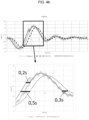
- FIG. 4a it is represented a measurement curve obtained from the measurement of the primary sway (angle) of the suspended load given by the angle sensor and a model curve of the mathematical model of the primary sway. After the measurement, it is applied a period filter which implies a time delay (0,3 second in this example).
- the period filter is a low pass filter set to remove the variations due to the secondary sway.
- the secondary sway phenomena may occur when the reeving system distance is small, corresponding more or less to the length of the cable between the trolley and the tool.
- a secondary sway phenomena may depend also on the global equivalent center of gravity.
- the load may balance in an arc below the trolley from the vertical axe, in a direction parallel to the trolley travel direction.
- the rotation axis is situated around the upper part of the reeving system linked to the trolley.
- the tool may further balance in an arc below the trolley from the axe of the global equivalent center of gravity, in a direction parallel to the trolley travel direction.
- the rotation axis is situated between the lower part of the reeving system linked to the tool and the center of gravity of the load.
- the configuration of the period filter depends on the period of the secondary sway. As the secondary sway may vary and depends on the length of the cable, the configuration of the period filter can be dynamic and depends on the current length of the cable.
- the periodic filter is set with a delay slightly above the period of the secondary sway.
- the period of the secondary sway is 0,25s and the delay of the periodic filter is set to 0,3s.
- the graphic below represents a zoom in the aera delimited by a rectangle.
- the periodic filter provides a time delay of 0,3 second that can be clearly seen when the angle of the primary sway equals to zero.
- the mathematical model can be shifted based on the calculated difference.
- the curve of the measurement of the primary sway follows the curve of the mathematical model which is thus considered synchronized.
- FIG. 4b it is represented the measurement curve of the primary sway of the suspended load, the model curve of the mathematical model of the primary sway and the filtered curve of the filtered measurement with an adapted filter.
- the measurement curve does not follow the model curve (modelized sway) of the mathematical model which is thus considered desynchronized.
- the graphic below represents a zoom in the aera delimited by a rectangle. Because the normal value should be 0,3 second, it means that the mathematical model is in advance of the difference, i.e. 0,2 second. The mathematical model can be then resynchronized by shifting in time this latter by a value of 0,2 second. The synchronization can be done for example once the angle of the filtered measurement equals to zero, allowing to calculate the difference between the filtered measurement and the mathematical model.
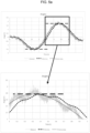
- FIG. 5a it is represented the measurement curve of the measurement of the primary sway (angle) of the suspended load given by the angle sensor and the model curve of the mathematical model of the primary sway. After the measurement, it is applied an amplitude filter which implies a time delay (0,1 second in this example).
- the amplitude filter is a low pass filter set to remove partly the variations due to du to "perturbation caused by mechanical vibration (high frequency)".
- the configuration of the amplitude filter depends on the period of the secondary sway. As the secondary sway may vary and depends on the length of the cable, the configuration of the amplitude filter can be dynamic and depends on the current length of the cable.
- the amplitude filter is set with a delay included in the period of the secondary sway. In one embodiment, the amplitude filter is set with a delay included between a quarter and a half of the period of the secondary sway. In one example, the period of the secondary sway is 0,25s and the delay of the amplitude filter is set to 0,1s. Such configuration allows an amplitude offset that is accurate despite remaining of variations of the measurement curve.
- the graphic below represents a zoom in the area delimited by a rectangle.
- the amplitude filter provides a time delay of 0,1 second that can be clearly seen when the angle of the primary sway is maximum (almost 1,8°).
- the model is desynchronized and needs an amplitude correction.
- the mathematical model can be shifted based on the calculated difference.
- the curve of the measurement of the primary sway follows in amplitude the curve of the mathematical model which is thus considered synchronized.
- FIG. 5b it is represented the measurement curve of the measurement of the primary sway of the suspended load, the model curve of the mathematical model of the primary sway and the filtered curve of the filtered measurement with an adapted filter.
- the measurement curve does not follow in amplitude the model curve of the mathematical model which is thus considered desynchronized.
- the graphic below represents a zoom in the aera delimited by a rectangle.
- the value of the filtered measurement for an amplitude angle and the value of an amplitude angle of the mathematical model present a difference of "-0.46°". Just after the calculation of this difference (shown by a double arrow), the mathematical model is corrected in amplitude by applying the calculated difference.
- a method for optimizing a model used by an antisway function for the transport of a load by a hoisting appliance comprises steps S1 to S7.
- control device CD stores a mathematical model and implements an anti-sway algorithm that uses in real time the mathematical model to follow the theorical sways of the load during transport.
- the control device CD initiates the transport of the load and is configured to determine remarkable points of the mathematical model for synchronization of the model according to at least one of steps S4 and S7.
- step S1 the angle sensor AS performs measurements of angle of the load with respect to the trolley.
- the control device CD retrieves measurements from the angle sensor AS to produce a measurement curve representing a primary sway.
- the measurement curve presents unwanted information due for example to secondary sway or vibration.
- step S2 the control device CD applies a first filter, called period filter PF, to the measurement curve to obtain a first filtered measurement curve.
- the period filter PF is set with a delay slightly above the period of the secondary sway.
- step S3 the control device CD calculates a first difference of time between the model curve and the first filtered measurement curve.
- step S4 the control device CD synchronizes the model with the first calculated difference, by applying a time correction corresponding to the first calculated difference.
- the control device CD can use remarkable points of the model for synchronization, like a zero angle of the model curve and a zero angle of first filtered measurement curve.
- the model can be resynchronized thanks to the first filtered measurement curve just after calculation of the first difference.
- the time for resynchronization depends on the used remarkable point of the model curve and can be decided by the operator.
- step S5 the control device CD applies a second filter, called amplitude filter AF, to the first measurement curve to obtain a second filtered measurement curve.
- the amplitude filter is set with a delay less than the period of the secondary sway.
- step S6 the control device CD calculates a second difference of a maximum angle amplitude between the model curve and the second filtered measurement curve.
- step S7 the control device CD synchronizes the model with the second calculated difference, by applying an amplitude correction corresponding to the second calculated difference.
- An embodiment comprises a control device CD under the form of an apparatus comprising one or more processor(s), I/O interface(s), and a memory coupled to the processor(s).
- the processor(s) may be implemented as one or more microprocessors, microcomputers, microcontrollers, digital signal processors, central processing units, state machines, logic circuitries, and/or any devices that manipulate signals based on operational instructions.
- the processor(s) can be a single processing unit or a number of units, all of which could also include multiple computing units.
- the processor(s) are configured to fetch and execute computer-readable instructions stored in the memory.
- processor may be provided through the use of dedicated hardware as well as hardware capable of executing software in association with appropriate software.
- the functions may be provided by a single dedicated processor, by a single shared processor, or by a plurality of individual processors, some of which may be shared.
- explicit use of the term "processor” should not be construed to refer exclusively to hardware capable of executing software, and may implicitly include, without limitation, digital signal processor (DSP) hardware, network processor, application specific integrated circuit (ASIC), field programmable gate array (FPGA), read only memory (ROM) for storing software, random access memory (RAM), and non volatile storage.
- DSP digital signal processor
- ASIC application specific integrated circuit
- FPGA field programmable gate array
- ROM read only memory
- RAM random access memory
- non volatile storage Other hardware, conventional and/or custom, may also be included.
- the memory may include any computer-readable medium known in the art including, for example, volatile memory, such as static random access memory (SRAM) and dynamic random access memory (DRAM), and/or non-volatile memory, such as read only memory (ROM), erasable programmable ROM, flash memories, hard disks, optical disks, and magnetic tapes.
- volatile memory such as static random access memory (SRAM) and dynamic random access memory (DRAM)
- non-volatile memory such as read only memory (ROM), erasable programmable ROM, flash memories, hard disks, optical disks, and magnetic tapes.
- the memory includes modules and data.
- the modules include routines, programs, objects, components, data structures, etc., which perform particular tasks or implement particular abstract data types.
- the data serves as a repository for storing data processed, received, and generated by one or more of the modules.
- program storage devices for example, digital data storage media, which are machine or computer readable and encode machine-executable or computer-executable programs of instructions, where said instructions perform some or all of the steps of the described method.
- the program storage devices may be, for example, digital memories, magnetic storage media, such as a magnetic disks and magnetic tapes, hard drives, or optically readable digital data storage media.
Landscapes
- Engineering & Computer Science (AREA)
- Mechanical Engineering (AREA)
- Automation & Control Theory (AREA)
- Health & Medical Sciences (AREA)
- Artificial Intelligence (AREA)
- Computer Vision & Pattern Recognition (AREA)
- Evolutionary Computation (AREA)
- Medical Informatics (AREA)
- Software Systems (AREA)
- Physics & Mathematics (AREA)
- General Physics & Mathematics (AREA)
- Control And Safety Of Cranes (AREA)
Abstract
retrieve measurements of angles of the load (6) with respect to the trolley (2) to produce a measurement curve representing a primary sway of the load (6),
apply a first filter to the measurement curve to obtain a first filtered measurement curve,
calculate a first difference of time between the model curve and the first filtered measurement curve,
apply a second filter to the first measurement curve to obtain a second filtered measurement curve,
calculate a second difference of a maximum angle amplitude between the model curve and the second filtered measurement curve,
synchronize the model based on the first calculated difference or the second calculated difference.
Description
- The present invention generally relates to a method for an anti-sway function applied to a hoisting appliance that is spanning a warehouse, the hoisting appliance being arranged for carrying a load suspended by cables from a trolley that can move with the hoisting appliance.
- Hoisting
appliances 1 such as bridge cranes, gantry cranes or overhead travelling cranes usually comprise atrolley 2 which can move over a single girder or a set ofrails 3 along a horizontal axis Y, as shown inFIG. 1 . This first movement along the Y-axis is generally referred to as short travel movement and/or trolley movement. Depending on the type of appliance, the girder or the set ofrails 3, also referred to as bridge, may also be movable along a horizontal axis X perpendicular to the Y-axis, thus enabling the trolley to be moved along both the X- and Y-axes. This second movement along the X-axis is generally referred to as long travel movement and/or bridge, crane or gantry movement. The amount of available short travel along the Y-axis and long travel along the X-axis determines a hoisting area that is spanned by thehoist 1. - A
tool 4, also called load suspension device, is associated with a reeving system having cables which pass through thetrolley 2, the length of thecables 5 being controlled by thetrolley 2 to vary, thereby enabling displacement of aload 6 along a vertical axis Z, referred to as hoisting movement. - Transferring a suspended load across a warehouse, a hall, shipyard, metallurgic or nuclear plant, requires an operator to be very careful to prevent people, obstacles or objects that are present within the hoisting area from being hit or damaged in any way. Hence, in addition to size, swinging of the suspended load, commonly referred to as sway, is something that the operator needs to take in account when manoeuvring the load across the working place along a trajectory within the boundaries of the hoisting area.
- This complexity is what has hampered development of fully automated hoisting systems being capable of transferring suspended loads independently along a trajectory. Some advanced antisway functions are difficult and time consuming to put in place, which is mainly due to the large number of parameters that are variable and specific for each crane.
- Several solutions already exist to resolve sway issues and can be chosen depending on expected accuracy, environment conditions (rain, snow, dust, etc.), or targeted performance.
- On heavy industry factories, overhead cranes are necessary to handle heavy loads. For economical and efficiencies reasons such companies implement antisway system on their overhead crane to facilitate handling operation, to increase the quality of their finish products and to reduce mechanical constraint on crane avoiding premature wear of mechanical parts.
- In order to implement an antisway system providing high accuracy, high performance and able to work in a severe environment, a first solution is to use a close loop with sensors offering better accuracy and performance, and a second solution is to use an open loop without sensors allowing harsh environment.
- However for the first solution, there is no sensor able to operate under high temperature (over 100°C ambient temperatures) in steel making plants for example. Also most of the sensors are based on optical technologies (laser / infra red) and they are therefore sensitive to dust, snow, heavy rain, flying object such as plastic bags in waste industries. Besides, installation of sensor is sometime not possible because there is no energy available on the location or no available location to allow operation without any damage of the sensor.
- For the second solution, accuracy and performance issues of an open loop system are mainly resulting from the impossibility to model external behaviors, such as:
- Sway at the ignition of the movement
- Sway generated by the Wind on outdoor crane
- Sway resulting of mechanical behavior (rolling)
- Sway generating by the load geometry during the movement (mass distribution)
- Sway generated during taking off the load
- Sway generated by the handling tool
- All these behaviors generates a desynchronization of the model compared to the reality : it could be a periodical de-synchronism or it can be due to over or under estimation of the angle amplitude.
- Accordingly, there is a need for implementing an antisway system providing high accuracy, high performance and able to work in a severe environment.
- This summary is provided to introduce concepts related to the present inventive subject matter. This summary is not intended to identify essential features of the claimed subject matter nor is it intended for use in determining or limiting the scope of the claimed subject matter.
- In one implementation, there is provided a method for optimizing a model used in real time by an antisway function for the transport of a load by a hoisting appliance spanning a hoisting area and comprising a gantry and a trolley able to transport the load suspended to a hoist mechanism hosted in the trolley, wherein, when transported, the load presents a primary sway, the model comprising a model curve representing the theorical primary sway of the load over time, the method comprising in a control device:
- retrieving measurements of angles of the load with respect to the trolley to produce a measurement curve representing a primary sway of the load,
- applying a first filter to the measurement curve to obtain a first filtered measurement curve,
- calculating a first difference of time between the model curve and the first filtered measurement curve,
- applying a second filter to the first measurement curve to obtain a second filtered measurement curve,
- calculating a second difference of a maximum angle amplitude between the model curve and the second filtered measurement curve,
- synchronizing the model based on the first calculated difference or the second calculated difference.
- Advantageously there is provided a new architecture of antisway control combining sensor measurements with a model normally used in open loop architecture, able to work in a severe environment, even with not accurate angle measurements. The antisway control can use a simulated signal having the value of the primary sway and being clean of any other unwanted information (secondary sway, vibration, etc.).
- Sway model could provide during a short time a very clean and useful image of the sway. But after a long time, the model calculation could be false (amplitude or shift) due to parameters imprecision, for example related to severe environment. Thanks to measurement signal (after filtering), it is possible to resynchronize this model in real-time.
- Advantageously, the method can be implemented for a particular architecture of the anti-sway function in an automated system. A particularity is to center the function around a digital swing model, and to base the regulation on this digital swing.
- Indeed, the mathematical model can be synchronized using information already available that can be only remarkable points. Indeed, a mathematics model could be resynchronized with only one remarkable point, like a zero angle or a maximum angle.
- In an embodiment, the model is synchronized based on the first calculated difference, by applying a time correction corresponding to the first calculated difference.
- In an embodiment, the model is synchronized based on the second calculated difference, by applying an amplitude correction corresponding to the second calculated difference.
- In an embodiment, the first filter and the second filter are low pass filters of first order.
- In an embodiment, the first filter is set with a delay slightly above the period of a secondary sway of the load.
- In an embodiment, the second filter is set with a delay less than the period of a secondary sway of the load.
- In an embodiment, the first filter and the second filter are dynamic filters.
- In an embodiment, the first filter and the second filter are set dynamically with a delay depending on the secondary sway of the load.
- In another implementation, there is provided an apparatus for optimizing a model used in real time by an antisway function for the transport of a load by a hoisting appliance spanning a hoisting area and comprising a gantry and a trolley able to transport the load suspended to a hoist mechanism hosted in the trolley, wherein, when transported, the load presents a primary sway, the model comprising a model curve representing the theorical primary sway of the load over time, the apparatus comprising:
- one or more network interfaces to communicate with a telecommunication network;
- a processor coupled to the network interfaces and configured to execute one or more processes; and
- a memory configured to store a process executable by the processor, the process when executed operable to:
- retrieving measurements of angles of the load with respect to the trolley to produce a measurement curve representing a primary sway of the load,
- applying a first filter to the measurement curve to obtain a first filtered measurement curve,
- calculating a first difference of time between the model curve and the first filtered measurement curve,
- applying a second filter to the first measurement curve to obtain a second filtered measurement curve,
- calculating a second difference of a maximum angle amplitude between the model curve and the second filtered measurement curve,
- synchronizing the model based on the first calculated difference or the second calculated difference.
- In another implementation there is provided a computer-readable medium having embodied thereon a computer program for executing a method for optimizing a model used in real time by an antisway function for the transport of a load by a hoisting appliance. Said computer program comprises instructions which carry out steps according to the method according to the invention.
- The detailed description is described with reference to the accompanying figures. In the figures, the left-most digit(s) of a reference number identifies the figure in which the reference number first appears. The same numbers are used throughout the figures to reference like features and components. Some embodiments of system and/or methods in accordance with embodiments of the present subject matter are now described, by way of example only, and with reference to the accompanying figures, in which:
-
FIG. 1 shows schematically an example of a hoisting appliance; -
FIG. 2 shows schematically an example of a communication system for optimizing an anti-sway algorithm for the transport of a load by a hoisting appliance; -
FIG. 3 illustrates a representation of a primary sway over time; -
FIG. 4a illustrates a representation of a measurement curve of the primary sway, a model curve of the primary sway and a first filtered measurement curve ; -
FIG. 4b illustrates a representation of a first filtered measurement curve added to the measurement curve of the primary sway with the model curve of the primary sway for synchronization of the model curve; -
FIG. 5a illustrates another representation of a measurement curve of the primary sway, a model curve of the primary sway and a second filtered measurement curve; -
FIG. 5b illustrates another representation of a second filtered measurement curve added to the measurement curve of the primary sway with the model curve of the primary sway for synchronization of the model curve; -
FIG. 6 illustrates a flow chart illustrating a method for optimizing a model used by an antisway function for the transport of a load by a hoisting appliance according to one embodiment; - The same reference number represents the same element or the same type of element on all drawings.
- It should be appreciated by those skilled in the art that any block diagrams herein represent conceptual views of illustrative systems embodying the principles of the present subject matter. Similarly, it will be appreciated that any flow charts, flow diagrams, state transition diagrams, pseudo code, and the like represent various processes which may be substantially represented in computer readable medium and so executed by a computer or processor, whether or not such computer or processor is explicitly shown.
- The figures and the following description illustrate specific exemplary embodiments of the invention. It will thus be appreciated that those skilled in the art will be able to devise various arrangements that, although not explicitly described or shown herein, embody the principles of the invention and are included within the scope of the invention. Furthermore, any examples described herein are intended to aid in understanding the principles of the invention, and are to be construed as being without limitation to such specifically recited examples and conditions. As a result, the invention is not limited to the specific embodiments or examples described below, but by the claims and their equivalents.
- Referring to
FIG. 2 , a communication system for optimizing an antisway function for the transport of a load by a hoisting appliance comprises a control device CD, an angle sensor AS and a supervisory system SUP. - A hoisting area, such as a warehouse, a yard, a hall, or other working area, is provided with a supervisory system SUP that is an IT control system for supervision of the hoisting area. The supervisory system provides information to the control device CD for trajectory execution, authorization i.e. access management, and security in general.
- The control device CD is able to communicate with the supervisory system SUP and with the angle sensor AS through a telecommunication network TN. The telecommunication network may be a wired or wireless network, or a combination of wired and wireless networks. The telecommunication network can be associated with a packet network, for example, an IP ("Internet Protocol") high-speed network such as the Internet or an intranet, or even a companyspecific private network. The control device CD may be Programmable Logic Controllers (PLC) and other automation device able to implement industrial processes and able to communicate with the supervisory system for exchanging data such as requests, inputs, control data, etc.
- The angle sensor AS may be linked to the trolley and is configured to measure the angle of the load with respect to the trolley, i.e. the angle between the load and the vertical axis. The angle sensor AS reports the measured angles to the control device CD.
- The control device CD is configured to create a path to be followed by the crane for transporting a load from one place within the hoisting area to another. Usually, an anti-sway algorithm is used for the damping of sways of a load during the operation of the bridge crane, which provides the increase of a mechanism performance, reduces the risk of accidents and traumatic situations. Methods that are used to achieve this goal may include mathematical model and computer simulation.
- Some anti-sway systems in close loop can be based on the use of a load angle sensor. For example, an anti-sway algorithm takes as inputs dynamic parameters of hoisting appliance comprising the current position of the trolley and the current angle of the load with respect to the trolley. For an anti-sway system in open loop, the anti-sway algorithm is based on a mathematical model and does not use data coming from sensors, such as an angle sensor. In one embodiment, the anti-sway algorithm uses data coming from the angle sensor AS in order to adjust the mathematical model, that can be desynchronized with reality, for example in time or in amplitude.
- The control device CD is configured to determine remarkable points that can be used for optimizing an antisway function, by resynchronizing the mathematical model with at least one of the determined remarkable points. To that end, the control device uses filters applied to the angles measured by the angle sensor to calculate a deviation from the mathematical model and the filtered measurements at remarkable points of the mathematical model.
- Referring to
FIG. 3 , it is represented a primary sway of the suspended load along the axis the suspended load is moving on. During the transport of the load, the control device is using in real time the mathematical model to follow the theorical sways of the load during time. When the trolley is travelling, the suspended load presents an angle with respect to axis X or axis Y, corresponding to the primary sway. The mathematical model gives the amplitude of the sway with respect to time. The angle sensor gives the amplitude of the sway measurement with respect to time. The sway measurement corresponds to a raw value of a perturbated sway measurement. - The raw value of a perturbated sway measurement shows variations that may be due to at least a secondary sway (medium frequency) and perturbation caused by mechanical vibration (high frequency). When the model is synchronized with the reality, the curve of the sway measurement is superimposed on the curve of the model. When it is generated a desynchronization of the model comparing with the reality, there could be a periodical de-synchronism or an over estimation or under estimation of the angle amplitude.
- Referring to
FIG. 4a , it is represented a measurement curve obtained from the measurement of the primary sway (angle) of the suspended load given by the angle sensor and a model curve of the mathematical model of the primary sway. After the measurement, it is applied a period filter which implies a time delay (0,3 second in this example). - The period filter is a low pass filter set to remove the variations due to the secondary sway. The secondary sway phenomena may occur when the reeving system distance is small, corresponding more or less to the length of the cable between the trolley and the tool. A secondary sway phenomena may depend also on the global equivalent center of gravity.
- The difference between the primary sway and the secondary sway is quickly explained hereinafter. In case of primary sway, the load may balance in an arc below the trolley from the vertical axe, in a direction parallel to the trolley travel direction. The rotation axis is situated around the upper part of the reeving system linked to the trolley. In case of secondary sway, the tool may further balance in an arc below the trolley from the axe of the global equivalent center of gravity, in a direction parallel to the trolley travel direction. The rotation axis is situated between the lower part of the reeving system linked to the tool and the center of gravity of the load.
- The configuration of the period filter depends on the period of the secondary sway. As the secondary sway may vary and depends on the length of the cable, the configuration of the period filter can be dynamic and depends on the current length of the cable.
- In one embodiment, the periodic filter is set with a delay slightly above the period of the secondary sway. In one example, the period of the secondary sway is 0,25s and the delay of the periodic filter is set to 0,3s. Such configuration allows a time offset that is accurate despite a loss of accuracy in amplitude for the curve of the filtered measurement.
- The graphic below represents a zoom in the aera delimited by a rectangle. The periodic filter provides a time delay of 0,3 second that can be clearly seen when the angle of the primary sway equals to zero.
- It can then be calculated the difference between the filtered measurement and the mathematical model at a remarkable point as a zero angle (the sway is null) for example. As the expected delay is known, if the calculated difference is different from the expected delay, the mathematical model can be shifted based on the calculated difference. In this example, the curve of the measurement of the primary sway follows the curve of the mathematical model which is thus considered synchronized.
- Referring to
FIG. 4b , it is represented the measurement curve of the primary sway of the suspended load, the model curve of the mathematical model of the primary sway and the filtered curve of the filtered measurement with an adapted filter. The measurement curve does not follow the model curve (modelized sway) of the mathematical model which is thus considered desynchronized. - The graphic below represents a zoom in the aera delimited by a rectangle. Because the normal value should be 0,3 second, it means that the mathematical model is in advance of the difference, i.e. 0,2 second. The mathematical model can be then resynchronized by shifting in time this latter by a value of 0,2 second. The synchronization can be done for example once the angle of the filtered measurement equals to zero, allowing to calculate the difference between the filtered measurement and the mathematical model.
- Referring to
FIG. 5a , it is represented the measurement curve of the measurement of the primary sway (angle) of the suspended load given by the angle sensor and the model curve of the mathematical model of the primary sway. After the measurement, it is applied an amplitude filter which implies a time delay (0,1 second in this example). - The amplitude filter is a low pass filter set to remove partly the variations due to du to "perturbation caused by mechanical vibration (high frequency)".
- The configuration of the amplitude filter depends on the period of the secondary sway. As the secondary sway may vary and depends on the length of the cable, the configuration of the amplitude filter can be dynamic and depends on the current length of the cable.
- In one embodiment, the amplitude filter is set with a delay included in the period of the secondary sway. In one embodiment, the amplitude filter is set with a delay included between a quarter and a half of the period of the secondary sway. In one example, the period of the secondary sway is 0,25s and the delay of the amplitude filter is set to 0,1s. Such configuration allows an amplitude offset that is accurate despite remaining of variations of the measurement curve.
- The graphic below represents a zoom in the area delimited by a rectangle. The amplitude filter provides a time delay of 0,1 second that can be clearly seen when the angle of the primary sway is maximum (almost 1,8°).
- If the maximum value of the mathematical model is different from the value of the filtered measurement, the model is desynchronized and needs an amplitude correction.
- It can then be calculated the difference between the filtered measurement and the mathematical model at a remarkable point as a maximum angle (the sway is maximum) for example. If the calculated difference is not null, the mathematical model can be shifted based on the calculated difference. In this example, the curve of the measurement of the primary sway follows in amplitude the curve of the mathematical model which is thus considered synchronized.
- Referring to
FIG. 5b , it is represented the measurement curve of the measurement of the primary sway of the suspended load, the model curve of the mathematical model of the primary sway and the filtered curve of the filtered measurement with an adapted filter. The measurement curve does not follow in amplitude the model curve of the mathematical model which is thus considered desynchronized. - The graphic below represents a zoom in the aera delimited by a rectangle. The value of the filtered measurement for an amplitude angle and the value of an amplitude angle of the mathematical model present a difference of "-0.46°". Just after the calculation of this difference (shown by a double arrow), the mathematical model is corrected in amplitude by applying the calculated difference.
- With reference to
FIG. 6 , a method for optimizing a model used by an antisway function for the transport of a load by a hoisting appliance according to one embodiment of the invention comprises steps S1 to S7. - Initially, the control device CD stores a mathematical model and implements an anti-sway algorithm that uses in real time the mathematical model to follow the theorical sways of the load during transport. The control device CD initiates the transport of the load and is configured to determine remarkable points of the mathematical model for synchronization of the model according to at least one of steps S4 and S7.
- In step S1, the angle sensor AS performs measurements of angle of the load with respect to the trolley. The control device CD retrieves measurements from the angle sensor AS to produce a measurement curve representing a primary sway.
- The measurement curve presents unwanted information due for example to secondary sway or vibration.
- In step S2, the control device CD applies a first filter, called period filter PF, to the measurement curve to obtain a first filtered measurement curve. The period filter PF is set with a delay slightly above the period of the secondary sway.
- In step S3, the control device CD calculates a first difference of time between the model curve and the first filtered measurement curve.
- In step S4, the control device CD synchronizes the model with the first calculated difference, by applying a time correction corresponding to the first calculated difference.
- The control device CD can use remarkable points of the model for synchronization, like a zero angle of the model curve and a zero angle of first filtered measurement curve.
- The model can be resynchronized thanks to the first filtered measurement curve just after calculation of the first difference. The time for resynchronization depends on the used remarkable point of the model curve and can be decided by the operator.
- In step S5, the control device CD applies a second filter, called amplitude filter AF, to the first measurement curve to obtain a second filtered measurement curve. The amplitude filter is set with a delay less than the period of the secondary sway.
- In step S6, the control device CD calculates a second difference of a maximum angle amplitude between the model curve and the second filtered measurement curve.
- In step S7, the control device CD synchronizes the model with the second calculated difference, by applying an amplitude correction corresponding to the second calculated difference.
- The order of sequences of steps S2-S4 and S5-S7 is interchangeable, representing two possibilities of resynchronization of the model.
- An embodiment comprises a control device CD under the form of an apparatus comprising one or more processor(s), I/O interface(s), and a memory coupled to the processor(s). The processor(s) may be implemented as one or more microprocessors, microcomputers, microcontrollers, digital signal processors, central processing units, state machines, logic circuitries, and/or any devices that manipulate signals based on operational instructions. The processor(s) can be a single processing unit or a number of units, all of which could also include multiple computing units. Among other capabilities, the processor(s) are configured to fetch and execute computer-readable instructions stored in the memory.
- The functions realized by the processor may be provided through the use of dedicated hardware as well as hardware capable of executing software in association with appropriate software. When provided by a processor, the functions may be provided by a single dedicated processor, by a single shared processor, or by a plurality of individual processors, some of which may be shared. Moreover, explicit use of the term "processor" should not be construed to refer exclusively to hardware capable of executing software, and may implicitly include, without limitation, digital signal processor (DSP) hardware, network processor, application specific integrated circuit (ASIC), field programmable gate array (FPGA), read only memory (ROM) for storing software, random access memory (RAM), and non volatile storage. Other hardware, conventional and/or custom, may also be included.
- The memory may include any computer-readable medium known in the art including, for example, volatile memory, such as static random access memory (SRAM) and dynamic random access memory (DRAM), and/or non-volatile memory, such as read only memory (ROM), erasable programmable ROM, flash memories, hard disks, optical disks, and magnetic tapes. The memory includes modules and data. The modules include routines, programs, objects, components, data structures, etc., which perform particular tasks or implement particular abstract data types. The data, amongst other things, serves as a repository for storing data processed, received, and generated by one or more of the modules.
- A person skilled in the art will readily recognize that steps of the methods, presented above, can be performed by programmed computers. Herein, some embodiments are also intended to cover program storage devices, for example, digital data storage media, which are machine or computer readable and encode machine-executable or computer-executable programs of instructions, where said instructions perform some or all of the steps of the described method. The program storage devices may be, for example, digital memories, magnetic storage media, such as a magnetic disks and magnetic tapes, hard drives, or optically readable digital data storage media.
- Although the present invention has been described above with reference to specific embodiments, it is not intended to be limited to the specific form set forth herein. Rather, the invention is limited only by the accompanying claims and, other embodiments than the specific above are equally possible within the scope of these appended claims.
- Furthermore, although exemplary embodiments have been described above in some exemplary combination of components and/or functions, it should be appreciated that, alternative embodiments may be provided by different combinations of members and/or functions without departing from the scope of the present disclosure. In addition, it is specifically contemplated that a particular feature described, either individually or as part of an embodiment, can be combined with other individually described features, or parts of other embodiments
Claims (10)
- Method for optimizing a model used in real time by an antisway function for the transport of a load by a hoisting appliance spanning a hoisting area and comprising a gantry and a trolley able to transport the load suspended to a hoist mechanism hosted in the trolley, wherein, when transported, the load presents a primary sway, the model comprising a model curve representing the theorical primary sway of the load over time, the method comprising in a control device (CD):retrieving (S1) measurements of angles of the load with respect to the trolley to produce a measurement curve representing a primary sway of the load,applying (S2) a first filter to the measurement curve to obtain a first filtered measurement curve,calculating (S3) a first difference of time between the model curve and the first filtered measurement curve,applying (S5) a second filter to the first measurement curve to obtain a second filtered measurement curve,calculating (S6) a second difference of a maximum angle amplitude between the model curve and the second filtered measurement curve,synchronizing (S4; S7) the model based on the first calculated difference or the second calculated difference.
- A method according to claim 1, wherein the model is synchronized based on the first calculated difference, by applying a time correction corresponding to the first calculated difference.
- A method according to any of previous claims, wherein the model is synchronized based on the second calculated difference, by applying an amplitude correction corresponding to the second calculated difference.
- A method according to any of previous claims, wherein the first filter and the second filter are low pass filters of first order.
- A method according to any of previous claims, wherein the first filter is set with a delay slightly above the period of a secondary sway of the load.
- A method according to any of previous claims, wherein the second filter is set with a delay less than the period of a secondary sway of the load.
- A method according to any of previous claims, wherein the first filter and the second filter are dynamic filters.
- A method according to any of claims 5 to 7, wherein the first filter and the second filter are set dynamically with a delay depending on the secondary sway of the load.
- An apparatus for optimizing a model used in real time by an antisway function for the transport of a load by a hoisting appliance spanning a hoisting area and comprising a gantry and a trolley able to transport the load suspended to a hoist mechanism hosted in the trolley, wherein, when transported, the load presents a primary sway, the model comprising a model curve representing the theorical primary sway of the load over time, the apparatus comprising:one or more network interfaces to communicate with a telecommunication network;a processor coupled to the network interfaces and configured to execute one or more processes; anda memory configured to store a process executable by the processor, the process when executed operable to:retrieving measurements of angles of the load with respect to the trolley to produce a measurement curve representing a primary sway of the load,applying a first filter to the measurement curve to obtain a first filtered measurement curve,calculating a first difference of time between the model curve and the first filtered measurement curve,applying a second filter to the first measurement curve to obtain a second filtered measurement curve,calculating a second difference of a maximum angle amplitude between the model curve and the second filtered measurement curve,synchronizing the model based on the first calculated difference or the second calculated difference.
- A computer-readable medium having embodied thereon a computer program for executing a method for optimizing a model used in real time by an antisway function for the transport of a load by a hoisting appliance according to any of claims 1 to 8.
Priority Applications (6)
| Application Number | Priority Date | Filing Date | Title |
|---|---|---|---|
| ES22306000T ES3061783T3 (en) | 2022-07-05 | 2022-07-05 | Method to optimize an anti-sway function |
| EP22306000.5A EP4303167B1 (en) | 2022-07-05 | 2022-07-05 | Method to optimize an anti-sway function |
| PCT/EP2023/066269 WO2024008417A1 (en) | 2022-07-05 | 2023-06-16 | Method to optimize an anti-sway function |
| CA3265122A CA3265122A1 (en) | 2022-07-05 | 2023-06-16 | Method to optimize an anti-sway function |
| CN202380061880.0A CN119768359A (en) | 2022-07-05 | 2023-06-16 | Methods for optimizing anti-sway function |
| US18/995,423 US20260125246A1 (en) | 2022-07-05 | 2023-06-16 | Method to optimize an anti-sway function |
Applications Claiming Priority (1)
| Application Number | Priority Date | Filing Date | Title |
|---|---|---|---|
| EP22306000.5A EP4303167B1 (en) | 2022-07-05 | 2022-07-05 | Method to optimize an anti-sway function |
Publications (2)
| Publication Number | Publication Date |
|---|---|
| EP4303167A1 true EP4303167A1 (en) | 2024-01-10 |
| EP4303167B1 EP4303167B1 (en) | 2025-11-19 |
Family
ID=83151798
Family Applications (1)
| Application Number | Title | Priority Date | Filing Date |
|---|---|---|---|
| EP22306000.5A Active EP4303167B1 (en) | 2022-07-05 | 2022-07-05 | Method to optimize an anti-sway function |
Country Status (6)
| Country | Link |
|---|---|
| US (1) | US20260125246A1 (en) |
| EP (1) | EP4303167B1 (en) |
| CN (1) | CN119768359A (en) |
| CA (1) | CA3265122A1 (en) |
| ES (1) | ES3061783T3 (en) |
| WO (1) | WO2024008417A1 (en) |
Cited By (2)
| Publication number | Priority date | Publication date | Assignee | Title |
|---|---|---|---|---|
| EP4640612A1 (en) * | 2024-04-23 | 2025-10-29 | Schneider Electric Industries Sas | Method and apparatus to optimize an anti-sway function |
| EP4640613A1 (en) * | 2024-04-23 | 2025-10-29 | Schneider Electric Industries Sas | Method and apparatus to optimize an anti-sway function |
Citations (2)
| Publication number | Priority date | Publication date | Assignee | Title |
|---|---|---|---|---|
| US9108826B2 (en) * | 2011-09-20 | 2015-08-18 | Konecranes Plc | Crane control |
| US20160362280A1 (en) * | 2013-11-25 | 2016-12-15 | Vinati S.R.L. | A device and a process for controlling a swinging of a load suspended from a lifting apparatus |
-
2022
- 2022-07-05 EP EP22306000.5A patent/EP4303167B1/en active Active
- 2022-07-05 ES ES22306000T patent/ES3061783T3/en active Active
-
2023
- 2023-06-16 CA CA3265122A patent/CA3265122A1/en active Pending
- 2023-06-16 CN CN202380061880.0A patent/CN119768359A/en active Pending
- 2023-06-16 US US18/995,423 patent/US20260125246A1/en active Pending
- 2023-06-16 WO PCT/EP2023/066269 patent/WO2024008417A1/en not_active Ceased
Patent Citations (2)
| Publication number | Priority date | Publication date | Assignee | Title |
|---|---|---|---|---|
| US9108826B2 (en) * | 2011-09-20 | 2015-08-18 | Konecranes Plc | Crane control |
| US20160362280A1 (en) * | 2013-11-25 | 2016-12-15 | Vinati S.R.L. | A device and a process for controlling a swinging of a load suspended from a lifting apparatus |
Non-Patent Citations (2)
| Title |
|---|
| CASTILLO ET AL: "Intelligent adaptive model-based control of robotic dynamic systems with a hybrid fuzzy-neural approach", APPLIED SOFT COMPUTING, ELSEVIER, AMSTERDAM, NL, vol. 3, no. 4, 1 December 2003 (2003-12-01), pages 363 - 378, XP022034401, ISSN: 1568-4946, DOI: 10.1016/J.ASOC.2003.05.007 * |
| HIROKI SANO ET AL: "Anti-sway crane control based on dual state observer with sensor-delay correction", ADVANCED MOTION CONTROL, 2010 11TH IEEE INTERNATIONAL WORKSHOP ON, IEEE, PISCATAWAY, NJ, USA, 21 March 2010 (2010-03-21), pages 679 - 684, XP031676028, ISBN: 978-1-4244-6668-9 * |
Cited By (2)
| Publication number | Priority date | Publication date | Assignee | Title |
|---|---|---|---|---|
| EP4640612A1 (en) * | 2024-04-23 | 2025-10-29 | Schneider Electric Industries Sas | Method and apparatus to optimize an anti-sway function |
| EP4640613A1 (en) * | 2024-04-23 | 2025-10-29 | Schneider Electric Industries Sas | Method and apparatus to optimize an anti-sway function |
Also Published As
| Publication number | Publication date |
|---|---|
| CN119768359A (en) | 2025-04-04 |
| US20260125246A1 (en) | 2026-05-07 |
| CA3265122A1 (en) | 2024-01-11 |
| WO2024008417A1 (en) | 2024-01-11 |
| EP4303167B1 (en) | 2025-11-19 |
| ES3061783T3 (en) | 2026-04-07 |
Similar Documents
| Publication | Publication Date | Title |
|---|---|---|
| US11866302B2 (en) | Method to optimize an anti-sway function | |
| US20260125246A1 (en) | Method to optimize an anti-sway function | |
| US20240425328A1 (en) | Method to optimize an anti-sway function | |
| US20210032848A1 (en) | Method for an automatic movement of a working device and working device | |
| CN111196560A (en) | Method and system for dynamically adjusting dangerous area range of bridge crane | |
| AU2004322424B2 (en) | Process and system for avoiding collisions for moveable machines | |
| US12400180B2 (en) | Automatic inventory of a warehouse | |
| CN120972540A (en) | A robust control method for reducing sway during crane operation | |
| Helma | Active anti-sway crane control using partial state feedback from inertial sensor | |
| US20250326609A1 (en) | Method and apparatus to optimize an anti-sway function | |
| US20250326608A1 (en) | Method and apparatus to optimize an anti-sway function | |
| EP4640613A1 (en) | Method and apparatus to optimize an anti-sway function | |
| US20250197174A1 (en) | Method to operate hoisting appliance for accurate predictive maintenance | |
| Korytov et al. | Cargo transportation by bridge cranes along a predetermined trajectory without uncontrollable sways | |
| BR102025005163A2 (en) | METHOD AND APPARATUS FOR OPTIMIZING AN ANTI-OSCILATION FUNCTION | |
| FI3918138T3 (en) | Method for estimating the position and orientation status of multiple moving modules of a joint system | |
| Jakovlev et al. | Container Handling Operation Modeling | |
| CN121553838A (en) | Remote control grab bucket control method and system of hook type crane | |
| BR102025004880A2 (en) | METHOD AND APPARATUS FOR OPTIMIZING AN ANTI-BALANCE FUNCTION | |
| Kernagis et al. | Design and optimization of an automated modular system for distribution, movement and storage of goods | |
| Jakovlev et al. | Container Handling Operation Modeling and Estimation | |
| Johansson | Cooperative Circumnavigation for a Mobile Target Using Adaptive Estimation | |
| CN120964630A (en) | Driving three-axis linkage anti-shake positioning control method, device, equipment and storage medium | |
| JPH03277455A (en) | Load control system |
Legal Events
| Date | Code | Title | Description |
|---|---|---|---|
| PUAI | Public reference made under article 153(3) epc to a published international application that has entered the european phase |
Free format text: ORIGINAL CODE: 0009012 |
|
| STAA | Information on the status of an ep patent application or granted ep patent |
Free format text: STATUS: THE APPLICATION HAS BEEN PUBLISHED |
|
| AK | Designated contracting states |
Kind code of ref document: A1 Designated state(s): AL AT BE BG CH CY CZ DE DK EE ES FI FR GB GR HR HU IE IS IT LI LT LU LV MC MK MT NL NO PL PT RO RS SE SI SK SM TR |
|
| STAA | Information on the status of an ep patent application or granted ep patent |
Free format text: STATUS: REQUEST FOR EXAMINATION WAS MADE |
|
| 17P | Request for examination filed |
Effective date: 20240702 |
|
| RBV | Designated contracting states (corrected) |
Designated state(s): AL AT BE BG CH CY CZ DE DK EE ES FI FR GB GR HR HU IE IS IT LI LT LU LV MC MK MT NL NO PL PT RO RS SE SI SK SM TR |
|
| GRAP | Despatch of communication of intention to grant a patent |
Free format text: ORIGINAL CODE: EPIDOSNIGR1 |
|
| STAA | Information on the status of an ep patent application or granted ep patent |
Free format text: STATUS: GRANT OF PATENT IS INTENDED |
|
| INTG | Intention to grant announced |
Effective date: 20250813 |
|
| GRAS | Grant fee paid |
Free format text: ORIGINAL CODE: EPIDOSNIGR3 |
|
| GRAA | (expected) grant |
Free format text: ORIGINAL CODE: 0009210 |
|
| STAA | Information on the status of an ep patent application or granted ep patent |
Free format text: STATUS: THE PATENT HAS BEEN GRANTED |
|
| AK | Designated contracting states |
Kind code of ref document: B1 Designated state(s): AL AT BE BG CH CY CZ DE DK EE ES FI FR GB GR HR HU IE IS IT LI LT LU LV MC MK MT NL NO PL PT RO RS SE SI SK SM TR |
|
| REG | Reference to a national code |
Ref country code: CH Ref legal event code: F10 Free format text: ST27 STATUS EVENT CODE: U-0-0-F10-F00 (AS PROVIDED BY THE NATIONAL OFFICE) Effective date: 20251119 Ref country code: GB Ref legal event code: FG4D |
|
| REG | Reference to a national code |
Ref country code: DE Ref legal event code: R096 Ref document number: 602022025191 Country of ref document: DE |
|
| REG | Reference to a national code |
Ref country code: IE Ref legal event code: FG4D |
|
| REG | Reference to a national code |
Ref country code: NL Ref legal event code: MP Effective date: 20251119 |
|
| REG | Reference to a national code |
Ref country code: ES Ref legal event code: FG2A Ref document number: 3061783 Country of ref document: ES Kind code of ref document: T3 Effective date: 20260407 |
|
| REG | Reference to a national code |
Ref country code: LT Ref legal event code: MG9D |
|
| PG25 | Lapsed in a contracting state [announced via postgrant information from national office to epo] |
Ref country code: NO Free format text: LAPSE BECAUSE OF FAILURE TO SUBMIT A TRANSLATION OF THE DESCRIPTION OR TO PAY THE FEE WITHIN THE PRESCRIBED TIME-LIMIT Effective date: 20260219 |
|
| PG25 | Lapsed in a contracting state [announced via postgrant information from national office to epo] |
Ref country code: AT Free format text: LAPSE BECAUSE OF FAILURE TO SUBMIT A TRANSLATION OF THE DESCRIPTION OR TO PAY THE FEE WITHIN THE PRESCRIBED TIME-LIMIT Effective date: 20251119 Ref country code: FI Free format text: LAPSE BECAUSE OF FAILURE TO SUBMIT A TRANSLATION OF THE DESCRIPTION OR TO PAY THE FEE WITHIN THE PRESCRIBED TIME-LIMIT Effective date: 20251119 Ref country code: HR Free format text: LAPSE BECAUSE OF FAILURE TO SUBMIT A TRANSLATION OF THE DESCRIPTION OR TO PAY THE FEE WITHIN THE PRESCRIBED TIME-LIMIT Effective date: 20251119 |
|
| REG | Reference to a national code |
Ref country code: AT Ref legal event code: MK05 Ref document number: 1858688 Country of ref document: AT Kind code of ref document: T Effective date: 20251119 |
|
| PG25 | Lapsed in a contracting state [announced via postgrant information from national office to epo] |
Ref country code: NL Free format text: LAPSE BECAUSE OF FAILURE TO SUBMIT A TRANSLATION OF THE DESCRIPTION OR TO PAY THE FEE WITHIN THE PRESCRIBED TIME-LIMIT Effective date: 20251119 |
|
| PG25 | Lapsed in a contracting state [announced via postgrant information from national office to epo] |
Ref country code: RS Free format text: LAPSE BECAUSE OF FAILURE TO SUBMIT A TRANSLATION OF THE DESCRIPTION OR TO PAY THE FEE WITHIN THE PRESCRIBED TIME-LIMIT Effective date: 20260219 |
|
| PG25 | Lapsed in a contracting state [announced via postgrant information from national office to epo] |
Ref country code: IS Free format text: LAPSE BECAUSE OF FAILURE TO SUBMIT A TRANSLATION OF THE DESCRIPTION OR TO PAY THE FEE WITHIN THE PRESCRIBED TIME-LIMIT Effective date: 20260319 |
|
| PG25 | Lapsed in a contracting state [announced via postgrant information from national office to epo] |
Ref country code: PT Free format text: LAPSE BECAUSE OF FAILURE TO SUBMIT A TRANSLATION OF THE DESCRIPTION OR TO PAY THE FEE WITHIN THE PRESCRIBED TIME-LIMIT Effective date: 20260319 |
|
| PG25 | Lapsed in a contracting state [announced via postgrant information from national office to epo] |
Ref country code: PL Free format text: LAPSE BECAUSE OF FAILURE TO SUBMIT A TRANSLATION OF THE DESCRIPTION OR TO PAY THE FEE WITHIN THE PRESCRIBED TIME-LIMIT Effective date: 20251119 |
|
| PG25 | Lapsed in a contracting state [announced via postgrant information from national office to epo] |
Ref country code: LV Free format text: LAPSE BECAUSE OF FAILURE TO SUBMIT A TRANSLATION OF THE DESCRIPTION OR TO PAY THE FEE WITHIN THE PRESCRIBED TIME-LIMIT Effective date: 20251119 |
|
| PG25 | Lapsed in a contracting state [announced via postgrant information from national office to epo] |
Ref country code: BG Free format text: LAPSE BECAUSE OF FAILURE TO SUBMIT A TRANSLATION OF THE DESCRIPTION OR TO PAY THE FEE WITHIN THE PRESCRIBED TIME-LIMIT Effective date: 20251119 |