EP4303121A1 - Airfoil with flexible trailing edge - Google Patents
Airfoil with flexible trailing edge Download PDFInfo
- Publication number
- EP4303121A1 EP4303121A1 EP23183964.8A EP23183964A EP4303121A1 EP 4303121 A1 EP4303121 A1 EP 4303121A1 EP 23183964 A EP23183964 A EP 23183964A EP 4303121 A1 EP4303121 A1 EP 4303121A1
- Authority
- EP
- European Patent Office
- Prior art keywords
- skin
- spar
- airfoil
- bottom skin
- trailing edge
- Prior art date
- Legal status (The legal status is an assumption and is not a legal conclusion. Google has not performed a legal analysis and makes no representation as to the accuracy of the status listed.)
- Pending
Links
Images



Classifications
-
- B—PERFORMING OPERATIONS; TRANSPORTING
- B64—AIRCRAFT; AVIATION; COSMONAUTICS
- B64C—AEROPLANES; HELICOPTERS
- B64C3/00—Wings
- B64C3/38—Adjustment of complete wings or parts thereof
- B64C3/44—Varying camber
-
- B—PERFORMING OPERATIONS; TRANSPORTING
- B64—AIRCRAFT; AVIATION; COSMONAUTICS
- B64C—AEROPLANES; HELICOPTERS
- B64C3/00—Wings
- B64C3/38—Adjustment of complete wings or parts thereof
- B64C3/44—Varying camber
- B64C3/48—Varying camber by relatively-movable parts of wing structures
-
- B—PERFORMING OPERATIONS; TRANSPORTING
- B64—AIRCRAFT; AVIATION; COSMONAUTICS
- B64C—AEROPLANES; HELICOPTERS
- B64C23/00—Influencing air flow over aircraft surfaces, not otherwise provided for
- B64C23/06—Influencing air flow over aircraft surfaces, not otherwise provided for by generating vortices
- B64C23/065—Influencing air flow over aircraft surfaces, not otherwise provided for by generating vortices at the wing tips
- B64C23/069—Influencing air flow over aircraft surfaces, not otherwise provided for by generating vortices at the wing tips using one or more wing tip airfoil devices, e.g. winglets, splines, wing tip fences or raked wingtips
- B64C23/076—Influencing air flow over aircraft surfaces, not otherwise provided for by generating vortices at the wing tips using one or more wing tip airfoil devices, e.g. winglets, splines, wing tip fences or raked wingtips the wing tip airfoil devices comprising one or more separate moveable members thereon affecting the vortices, e.g. flaps
-
- B—PERFORMING OPERATIONS; TRANSPORTING
- B64—AIRCRAFT; AVIATION; COSMONAUTICS
- B64C—AEROPLANES; HELICOPTERS
- B64C3/00—Wings
- B64C3/18—Spars; Ribs; Stringers
-
- B—PERFORMING OPERATIONS; TRANSPORTING
- B64—AIRCRAFT; AVIATION; COSMONAUTICS
- B64C—AEROPLANES; HELICOPTERS
- B64C3/00—Wings
- B64C3/18—Spars; Ribs; Stringers
- B64C3/182—Stringers, longerons
-
- B—PERFORMING OPERATIONS; TRANSPORTING
- B64—AIRCRAFT; AVIATION; COSMONAUTICS
- B64C—AEROPLANES; HELICOPTERS
- B64C3/00—Wings
- B64C3/26—Construction, shape, or attachment of separate skins, e.g. panels
-
- B—PERFORMING OPERATIONS; TRANSPORTING
- B64—AIRCRAFT; AVIATION; COSMONAUTICS
- B64C—AEROPLANES; HELICOPTERS
- B64C3/00—Wings
- B64C3/38—Adjustment of complete wings or parts thereof
-
- B—PERFORMING OPERATIONS; TRANSPORTING
- B64—AIRCRAFT; AVIATION; COSMONAUTICS
- B64C—AEROPLANES; HELICOPTERS
- B64C3/00—Wings
- B64C3/38—Adjustment of complete wings or parts thereof
- B64C3/52—Warping
-
- B—PERFORMING OPERATIONS; TRANSPORTING
- B64—AIRCRAFT; AVIATION; COSMONAUTICS
- B64C—AEROPLANES; HELICOPTERS
- B64C9/00—Adjustable control surfaces or members, e.g. rudders
- B64C9/14—Adjustable control surfaces or members, e.g. rudders forming slots
- B64C9/16—Adjustable control surfaces or members, e.g. rudders forming slots at the rear of the wing
- B64C9/18—Adjustable control surfaces or members, e.g. rudders forming slots at the rear of the wing by single flaps
-
- Y—GENERAL TAGGING OF NEW TECHNOLOGICAL DEVELOPMENTS; GENERAL TAGGING OF CROSS-SECTIONAL TECHNOLOGIES SPANNING OVER SEVERAL SECTIONS OF THE IPC; TECHNICAL SUBJECTS COVERED BY FORMER USPC CROSS-REFERENCE ART COLLECTIONS [XRACs] AND DIGESTS
- Y02—TECHNOLOGIES OR APPLICATIONS FOR MITIGATION OR ADAPTATION AGAINST CLIMATE CHANGE
- Y02T—CLIMATE CHANGE MITIGATION TECHNOLOGIES RELATED TO TRANSPORTATION
- Y02T50/00—Aeronautics or air transport
- Y02T50/10—Drag reduction
Definitions
- the disclosure relates generally to aircraft wings.
- Aircrafts are typically designed to have optimal aerodynamic characteristics at a single point in their flight envelope.
- wing tip devices are typically used to improve aerodynamic performance at cruise and take-off.
- the altitude and the fuel loading change continuously throughout the flight, and the aircraft may often have to fly at non-optimal flight conditions.
- the aircraft may also operate at Mach numbers that can be significantly different from the ones used as the design condition. The resulting sub-optimal performance may affect the fuel efficiency of the aircraft.
- an aircraft control surface comprising: a spar extending in a span-wise direction, the spar having at least one aperture extending through the spar; a displacement guide adjacent to the at least one aperture of the spar; an airfoil mounted to the spar and extending in the span-wise direction, the airfoil extending in a chord-wise direction between a leading edge and a trailing edge, the airfoil comprising: a top skin being resiliently deformable and mounted to the spar via a leaf spring, the top skin being bendable relative to the spar, the top skin extending from the spar in the chord-wise direction to a top skin rear edge; a bottom skin being resiliently deformable and disposed beneath the top skin, part of the bottom skin being displaceable in the chord-wise direction through the at least one aperture of the spar and configured to be guided through the at least one aperture by the displacement guide, the bottom skin extending in the chord-wise direction from the spar to a bottom skin rear edge, the bottom skin rear edge joined to the top skin rear edge
- the displacement guide includes at least one roller and at least one roller guideway configured for guiding the part of the bottom skin through the at least one aperture of the spar.
- top skin and the bottom skin define an internal cavity of the airfoil, the internal cavity configured to vary with the displacement of the bottom skin.
- a winglet for an aircraft the winglet coupled to a main wing section of an aircraft wing, the winglet comprising: a main winglet section extending between a root portion and a distal portion, the main winglet section having a forward spar and an aft spar extending through an internal cavity of the main winglet section along a span thereof, the forward and aft spars being spaced apart in a chord-wise direction at the distal portion of the main winglet section, the aft spar having at least one aperture extending through the aft spar; a displacement guide adjacent to the at least one aperture of the aft spar; an airfoil mounted to the aft spar and extending in a span-wise direction, the airfoil extending in a chord-wise direction between a leading edge and a trailing edge, the airfoil comprising: a top skin being resiliently deformable and mounted to the aft spar via a leaf spring,
- the displacement guide includes at least one roller and at least one roller guideway configured for guiding the part of the bottom skin through the at least one aperture of the aft spar.
- top skin and the bottom skin define an internal cavity of the airfoil, the internal cavity configured to vary with the displacement of the bottom skin.
- the winglet as previously defined, wherein the internal cavity includes a solid trailing edge portion at the trailing edge.
- the winglet as previously defined, wherein the interior cavity includes a plurality of airfoil supports extending between the top skin and the bottom skin.
- the winglet as previously defined, wherein the actuator is directly connected to at least one finger protruding from the bottom skin at the leading edge and is configured to effect displacement of the at least one finger through the at least one aperture.
- the aircraft 1 has a fuselage 2 having a fore end and an aft end, with a cabin generally located between the cockpit and the tail assembly.
- a tail assembly comprises a vertical stabilizer 3 with a rudder, and horizontal stabilizers 4 with elevators.
- the tail assembly has a fuselage-mounted tail, but other configurations may also be used for the aircraft 1, such as cruciform, T-tail, etc.
- Wings 10 project laterally from the fuselage 2.
- the aircraft 1 has engines 6 supported by the wings 10 in the depicted embodiment, although for other aircraft they can be mounted to the fuselage 2.
- the aircraft 1 is shown as a jet-engine aircraft, but may also be a propeller aircraft. It is also understood that the aircraft 1 can be a business aircraft, alternately it can be any other type of aircraft, manned or unmanned, including, but not limited to, a commercial aircraft or a military aircraft.
- FIG. 1B shows one of the wings 10 of the aircraft 1.
- the wing 10 has a main wing section 11 which forms the corpus of the wing 10 and provides structure thereto.
- the main wing section 11 makes up the bulk of the wing 10, and is responsible for almost all of the lift produced by the wing 10.
- the main wing section 11 has a span S, which forms part of the wing span of the aircraft 1 in the depicted embodiment.
- the span S is defined between a root portion 15A of the main wing section 11 and a tip or distal portion 15B of the main wing section 11.
- the root portion 15A is the portion of the wing 10 closest to the fuselage 2.
- the distal portion 15B is the portion of the main wing section 11 located furthest from the fuselage 2.
- the distal portion 15B is defined between a 50% position and a 100% position along the span S of the corresponding main wing section 11. In an embodiment, the distal portion 15B is defined between a 80% position and a 100% position along the span S of the main wing section 11.
- the main wing section 11 has an internal frame 12.
- the internal frame 12 includes any suitable interconnection of components to provide structure to the main wing section 11 so that it can support the loads acting on the wing 10 during flight of the aircraft 1.
- the internal frame 12 includes any suitable arrangement of spars, ribs, stringers, and other members.
- the internal frame 12 includes a front or forward spar 14A and a rear or aft spar 14B, which are interconnected by multiple transverse ribs 14C.
- the main wing section 11 also includes a skin 18 which covers the internal frame 12 and provides an aerodynamic outer surface which in the depicted embodiment, helps the wing 10 to generate lift.
- a cross-section of the skin 18 taken in a plane transverse to the span S shows the profile of the airfoil defined by the main wing section 11 at that location along the span S.
- a leading edge portion 18A of the skin 18 covers the forward spar 14A, and a trailing edge portion 18B of the skin 18 covers the aft spar 14B.
- the wing 10 has a first or upper skin portion 18C defining an uppermost outer surface of the skin 18 and a second or lower skin portion 18D defining a lowermost outer surface of the skin 18.
- the skin 18 is any suitable metal or composite material, and is closed on itself such that it defines an internal cavity 19 of the wing 10 and a housing for the internal frame 12.
- the wing 10 may include multiple flight control surfaces (e.g. flaps, spoilers, ailerons, etc.) which may, for instance, alter or improve the aerodynamic performance of the aircraft.
- the main wing section 11 includes an aileron 17 at the distal portion 15B of the main wing section 11, where the aileron 17 defines part of the trailing edge portion 18B of the main wing section 11.
- the forward and aft spars 14A, 14B are spaced apart to define and delimit a dry segment 16A of the internal cavity 19 of the wing 10.
- the internal cavity 19 is divided into dry segments 16A and wet segments 16B.
- the dry segments 16A are volumes of the internal cavity 19 which include components that contribute to the functioning of the wing 10, such as wiring, linkages, piping, etc.
- the wet segments 16B are volumes of the internal cavity 19 in which fuel accumulates.
- the wet segments 16B are enclosed volumes which form fuel tanks, and are typically positioned on the main wing section 11 closer to the root portion 15A to avoid large moments acting on the wing 10.
- the dry segment 16A of the internal cavity 19 at the distal portion 15B of the main wing section 11 is a volume that is delimited vertically by the upper and lower skin portions 18C, 18D, and is delimited in the chord-wise direction by the forward and aft spars 14A, 14B.
- the dry segment 16A in the depicted embodiment is positioned between the 50% position and the 100% position along the span S of the main wing section 11. In an embodiment, the dry segment 16A is positioned between the 80% position and the 100% position along the span S of the main wing section 11. In FIG.
- the dry segment 16A delimited by the forward and aft spars 14A,14B is disposed between the leading edge portion 18A of the main wing section 11 and the aileron 17 at the distal portion 15B of the main wing section 11.
- the volume of the dry segment 16A at the distal portion 15B of the main wing section 11 is less than the volume of other dry and wet segments 16A, 16B at positions along the span S that are closer to the root portion 15A.
- the volume of the dry segment 16A at the distal portion 15B of the main wing section 11 is smaller than the volume of all other dry and wet segments 16A,16B of the main wing section 11.
- the dry segment 16A at the distal portion 15B of the main wing section 11 is the closest of all the dry and wet segments 16A, 16B of the main wing section 11 to the tip of the wing 10. It will therefore be appreciated that the dry segment 16A of the internal cavity 19 at the distal portion 15B of the main wing section 11 is a relatively small and constrained internal volume of the main wing section 11.
- FIGS. 1A and 1B also show a winglet 20 of the wing 10 that may be fixedly or moveably attached to the main wing section 11.
- Winglet 20 may include a main winglet section with an internal frame 12 similar to that of the main wing section 11, i.e., that includes a front or forward spar 14A and a rear or aft spar 14B, which are interconnected by multiple transverse ribs 14C.
- Winglet 20 may similarly extend in a span-wise direction between a winglet root and a winglet tip and have a similar outer skin surface.
- Airfoil 30 may, for instance, act as a control surface for the aircraft 1 (or as a portion thereof), for instance at the trailing edge of the main wing section 11 or the winglet 20. Other positions for airfoil 30 may be contemplated.
- the airfoil 30 is joined to the winglet 20 at the aft spar 14B to act as the trailing edge of the winglet 20.
- an aircraft control surface may include the airfoil 30 and adjacent components of the wing main section 11 or winglet 20 to which the airfoil 30 is mounted.
- the airfoil 30 extends in a span-wise direction from an airfoil root 31 to an airfoil tip 32, and in a chord-wise direction between an airfoil leading edge 33 and an airfoil trailing edge 34.
- Airfoil 30 is mounted at its leading edge 33 to a spar extending in a span-wise direction through the component of the aircraft 1 to which the airfoil 30 is mounted, for instance an aft spar 14B of the main wing section 11 or of the winglet 20.
- the trailing edge 34 may be a tapered trailing edge 34 (i.e., its chord-wise length lessens from root 31 to tip 32). In such cases, the trailing edge 34 may not be parallel to the aft spar 14B.
- the airfoil 30 includes a top skin 35 and a bottom skin 36 that define an airfoil internal cavity 37.
- the top skin 35 also referred to as an upper skin, extends from the aft spar 14B to a top skin rear edge 38, while the bottom skin 35, also referred to as a lower skin, extends from the aft spar 14B to a bottom skin rear edge 39.
- 'rear' refers to a downstream direction of fluids traveling along the airfoil 30.
- the top skin rear edge 38 joins the bottom skin rear edge 39 to form the airfoil trailing edge 34.
- the airfoil internal cavity 37 is substantially hollow.
- the airfoil internal cavity 37 is solid at the airfoil trailing edge 34.
- This solid trailing edge 40 may occupy, for instance, approximately 5% of a chord length of the airfoil.
- the top skin 35 and bottom skin 36 are resiliently deformable and the bottom skin 36 is displaceable in and out of the aft spar 14B in the chord-wise direction, thereby allowing the airfoil 30, and more particularly the airfoil trailing edge 34, to displace upwardly (when the bottom skin 36 displaces out of the aft spar 14B) and downwardly (when the bottom skin 36 displaces into the aft spar 14B).
- the top skin 35 is fixedly mounted to the aft spar 14B at the airfoil leading edge 33 via one or more flexible mounts, illustratively leaf springs 41, which allow the top skin 35 to be resiliently deformable while maintaining the surface continuity on the top surface of the airfoil 30.
- the lead springs 41 may additionally relieve stress in the airfoil 30 by acting as a compliant joint between the top skin 35 and the aft spar 14B.
- resiliently deformable it is understood that the top skin 35 is bendable or pivotable relative to the aft spar 14B in an upward and downward direction, while also being compliant with any applicant standards for the airfoil 30 and load bearing requirements.
- the leaf springs 41 may take the form of slender, arc-shape lengths of spring steel (or other suitable material) of rectangular or other cross-sectional shapes. Other types of springs to mount the top skin 35 to the aft spar 14B in a similarly flexible manner may be contemplated. Other numbers of leaf springs 41 may be contemplated, for instance based on the span-wise length of the airfoil 30.
- the bottom skin 36 is disposed beneath the top skin 35 and is similarly resiliently deformable. At least a portion of the bottom skin 36 is displaceable in the chord-wise direction in and out of the aft spar 14B to either extend or shorten an effective length of the lower skin 36.
- the effective length of the bottom skin 36 may refer to a portion of the bottom skin 36 that is exposed to the ambient air, i.e., that is not contained within the aft spar 14B.
- the change of length of the bottom skin 36 causes the trailing edge 34 to displace upward or downward. In other words, the trailing edge 34 may be referred to as being flexible.
- the aft spar 14B has one or more apertures 42 through which portions of the bottom skin 36 displace.
- the bottom skin 36 may include one or more fingers 43 (or other like members) displaceable in and out of the one or more apertures 42, the number of fingers 43 corresponding with the number of apertures 42.
- three fingers 43 are displaceable in and out of three apertures 42, although these numbers may vary, for instance based on a span-wise length of the airfoil 30 and/or an overall weight of the airfoil 30.
- a displacement guide illustratively a plurality of rollers 44 and roller guideways 45, is provided adjacent the apertures 42 to guide the displacement of the fingers 43 in and out of the apertures 42.
- the fingers 43 roll along the rollers 44 and slide in and out of the apertures 42 via the roller guideways 45.
- the roller guideways 45 may include stops to define outer limits or bounds for the displacement of the fingers 43.
- four rollers 44 are provided, while the number of roller guideways 45 (three) corresponds with the number of fingers 43 and apertures 42.
- Other numbers of rollers 44 and roller guideways 45 may be contemplated.
- Other types of displacement guides may be contemplated.
- the fingers 43 are configured to displace in a direction perpendicularly to the aft spar 14B. In another embodiment, the fingers 43 may be configured to displace in a direction perpendicular to the tapered trailing edge 34.
- an actuator 46 is connected to the bottom skin 36 and is configured to displace (i.e., push and pull) the bottom skin 36 in the chord-wise direction to extend or retract the bottom skin 36 relative to the aft spar 14B, thereby causing the airfoil 30, and more particularly the trailing edge 34, to displace up and down.
- the actuator 46 may be connected to one or more of the fingers 43 to effect their displacement in and out of the apertures 42.
- a plurality of like actuators 46 may be provided, each connected to a corresponding finger 43.
- the actuator 46 may be connected directly to the finger(s) 43, for instance via a rod or other like connecting member, or indirectly, for instance via gearing or other linkages or cables.
- the actuator 46 may be a hydraulic actuator. Other actuator types may be contemplated.
- the top skin 35 and bottom skin 36 may be made from conventional skin materials such as sheet metals or composite sheets.
- the top skin 35 and bottom skin 36 of the airfoil 30 may be made from the same material as the skin 18 of the main wing section 11 and/or winglet 20. Other materials for the top skin 35 and bottom skin 36 may be contemplated.
- a volume of the airfoil internal cavity 37 may fluctuate as well.
- the trailing edge 34 includes a solid trailing edge 40
- the solid trailing edge 40 may maintain a constant shape as the airfoil 30 bends upward or downward.
- Displacement of the trailing edge 34 may, for instance, change the shape of the trailing edge 34.
- the chord length, camber and thickness of the trailing edge 34 may be controlled via said displacement.
- Various flight control requirements may dictate the displacement of the trailing edge 34.
- Actuation of the actuator 46 may be done manually, for instance by the pilot of the aircraft 1. Additionally or alternatively, the actuation process for the actuator 46 may be automated, for instance to displace the trailing edge 34 based on the flight stage and/or ambient conditions.
- the airfoil 30 is shown in a bent or deformed state.
- the airfoil 30 is shown with the trailing edge 34 bent in a downward direction, resulting from the bottom skin 36 being displaced by the actuator 46 into the aft spar 14B and the top skin 35 extending the leaf springs 41, thereby lowering the trailing edge 34.
- This is in relation to a neutral or unbent airfoil 30', also shown in FIG. 2 .
- the bottom skin 36' of unbent airfoil 30' is at a position with reference to the aft spar 14B such that the top skin 35' is in an unbent state.
- the top skin 35' neither compresses nor extends the lead springs 41 while in its unbent state.
- the unbent airfoil 30' may extend in a substantially parallel direction as the component to which it is mounted, for instant the main wing section 11 or the winglet 20.
- additional hardware may be provided to support and/or connect the airfoil 30 to the aft spar 14B.
- various supporting members 47 may be provided to support the airfoil 30.
- a leaf spring connecting plate 48 may be provided to couple the lead springs 41 to the aft spar 14B.
- An additional connecting plate 49 may be provided for joining the internal frame 12 to which the airfoil 30 is connected to another portion of the aircraft wing 10.
- the airfoil internal cavity 37 includes a plurality of airfoil supports 50 extending between the top skin 35 and the bottom skin 36.
- the supports extend across a span-wise length of the airfoil 30 and are spaced apart from one another in a chord-wise direction between the airfoil leading edge 33 and the airfoil trailing edge 34, illustratively the solid trailing edge 40.
- These supports 50 may provide additional stiffness to the airfoil.
- the number, spacing and stiffness of supports 50 may vary, for instance based on the weight of the airfoil 30.
- Other supporting means for airfoil 30 may be contemplated.
- Various combinations for internal cavities 37 with hollow spaces, various supports 50 and solid trailing edge 40 may be contemplated.
Landscapes
- Engineering & Computer Science (AREA)
- Aviation & Aerospace Engineering (AREA)
- Mechanical Engineering (AREA)
- Structures Of Non-Positive Displacement Pumps (AREA)
- Architecture (AREA)
- General Engineering & Computer Science (AREA)
Abstract
Description
- The disclosure relates generally to aircraft wings.
- Aircrafts are typically designed to have optimal aerodynamic characteristics at a single point in their flight envelope. For example, wing tip devices are typically used to improve aerodynamic performance at cruise and take-off. However, the altitude and the fuel loading change continuously throughout the flight, and the aircraft may often have to fly at non-optimal flight conditions. The aircraft may also operate at Mach numbers that can be significantly different from the ones used as the design condition. The resulting sub-optimal performance may affect the fuel efficiency of the aircraft.
- In one aspect, there is provided an aircraft control surface, comprising: a spar extending in a span-wise direction, the spar having at least one aperture extending through the spar; a displacement guide adjacent to the at least one aperture of the spar; an airfoil mounted to the spar and extending in the span-wise direction, the airfoil extending in a chord-wise direction between a leading edge and a trailing edge, the airfoil comprising: a top skin being resiliently deformable and mounted to the spar via a leaf spring, the top skin being bendable relative to the spar, the top skin extending from the spar in the chord-wise direction to a top skin rear edge; a bottom skin being resiliently deformable and disposed beneath the top skin, part of the bottom skin being displaceable in the chord-wise direction through the at least one aperture of the spar and configured to be guided through the at least one aperture by the displacement guide, the bottom skin extending in the chord-wise direction from the spar to a bottom skin rear edge, the bottom skin rear edge joined to the top skin rear edge to form the trailing edge of the airfoil; and an actuator connected to the bottom skin and configured to displace the bottom skin in the chord-wise direction, displacement of the bottom skin causing the trailing edge to displace up or down.
- The aircraft control surface as previously defined, wherein the spar is an aft spar of an aircraft wing.
- The aircraft control surface as previously defined, wherein the airfoil is mounted to a main wing section of the aircraft wing or to a winglet at a tip of the aircraft wing.
- The aircraft control surface as previously defined, wherein the displacement guide includes at least one roller and at least one roller guideway configured for guiding the part of the bottom skin through the at least one aperture of the spar.
- The aircraft control surface as previously defined, wherein the trailing edge is tapered relative to the leading edge.
- The aircraft control surface as previously defined, wherein the top skin and the bottom skin define an internal cavity of the airfoil, the internal cavity configured to vary with the displacement of the bottom skin.
- The aircraft control surface as previously defined, wherein the internal cavity includes a solid trailing edge portion at the trailing edge.
- The aircraft control surface as previously defined, wherein the solid trailing edge portion occupies approximately 5% of a chord length of the airfoil.
- The aircraft control surface as previously defined, wherein the interior cavity includes a plurality of airfoil supports extending between the top skin and the bottom skin.
- The aircraft control surface as previously defined, wherein the actuator is directly connected to at least one finger protruding from the bottom skin at the leading edge and is configured to effect displacement of the finger through the at least one aperture.
- In another aspect, there is provided a winglet for an aircraft, the winglet coupled to a main wing section of an aircraft wing, the winglet comprising: a main winglet section extending between a root portion and a distal portion, the main winglet section having a forward spar and an aft spar extending through an internal cavity of the main winglet section along a span thereof, the forward and aft spars being spaced apart in a chord-wise direction at the distal portion of the main winglet section, the aft spar having at least one aperture extending through the aft spar; a displacement guide adjacent to the at least one aperture of the aft spar; an airfoil mounted to the aft spar and extending in a span-wise direction, the airfoil extending in a chord-wise direction between a leading edge and a trailing edge, the airfoil comprising: a top skin being resiliently deformable and mounted to the aft spar via a leaf spring, the top skin being bendable relative to the aft spar, the top skin extending from the aft spar in the chord-wise direction to a top skin rear edge; a bottom skin being resiliently deformable and disposed beneath the top skin, part of the bottom skin being displaceable in the chord-wise direction through the at least one aperture of the aft spar and configured to be guided through the at least one aperture by the displacement guide, the bottom skin extending in the chord-wise direction from the aft spar to a bottom skin rear edge, the bottom skin rear edge joined to the top skin rear edge to form the trailing edge of the airfoil; and an actuator connected to the bottom skin and configured to displace the bottom skin in the chord-wise direction, displacement of the bottom skin causing the trailing edge to displace up or down.
- The winglet as previously defined, wherein the displacement guide includes at least one roller and at least one roller guideway configured for guiding the part of the bottom skin through the at least one aperture of the aft spar.
- The winglet as previously defined, wherein the trailing edge is tapered relative to the leading edge.
- The winglet as previously defined, wherein the top skin and the bottom skin define an internal cavity of the airfoil, the internal cavity configured to vary with the displacement of the bottom skin.
- The winglet as previously defined, wherein the internal cavity includes a solid trailing edge portion at the trailing edge.
- The winglet as previously defined, wherein the solid trailing edge portion occupies approximately 5% of a chord length of the airfoil.
- The winglet as previously defined, wherein the interior cavity includes a plurality of airfoil supports extending between the top skin and the bottom skin.
- The winglet as previously defined, wherein the actuator is directly connected to at least one finger protruding from the bottom skin at the leading edge and is configured to effect displacement of the at least one finger through the at least one aperture.
- Reference is now made to the accompanying figures in which:
-
FIG. 1A is a perspective view of an aircraft; -
FIG. 1B is a top view of a wing of the aircraft ofFIG. 1A , showing internal components of the wing; -
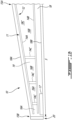
Fig. 2 is a perspective, partial cutaway view of an airfoil for the aircraft ofFIG. 1A ; -
Fig. 3 is an exploded perspective view of an airfoil for the aircraft ofFIG. 1A ; -
Fig. 4 is a partial cutaway view of an airfoil for the aircraft ofFIG. 1A ; and -
Fig. 5 is a perspective view of a bottom skin for the airfoil ofFIG. 4 . - Referring to the drawings and more particularly to
FIG. 1A , an aircraft is shown at 1, and is generally described to illustrate some components for reference purposes in the present disclosure. The aircraft 1 has afuselage 2 having a fore end and an aft end, with a cabin generally located between the cockpit and the tail assembly. A tail assembly comprises avertical stabilizer 3 with a rudder, andhorizontal stabilizers 4 with elevators. The tail assembly has a fuselage-mounted tail, but other configurations may also be used for the aircraft 1, such as cruciform, T-tail, etc. Wings 10 project laterally from thefuselage 2. The aircraft 1 hasengines 6 supported by thewings 10 in the depicted embodiment, although for other aircraft they can be mounted to thefuselage 2. The aircraft 1 is shown as a jet-engine aircraft, but may also be a propeller aircraft. It is also understood that the aircraft 1 can be a business aircraft, alternately it can be any other type of aircraft, manned or unmanned, including, but not limited to, a commercial aircraft or a military aircraft. -
FIG. 1B shows one of thewings 10 of the aircraft 1. Thewing 10 has amain wing section 11 which forms the corpus of thewing 10 and provides structure thereto. Themain wing section 11 makes up the bulk of thewing 10, and is responsible for almost all of the lift produced by thewing 10. Themain wing section 11 has a span S, which forms part of the wing span of the aircraft 1 in the depicted embodiment. The span S is defined between aroot portion 15A of themain wing section 11 and a tip ordistal portion 15B of themain wing section 11. Theroot portion 15A is the portion of thewing 10 closest to thefuselage 2. Thedistal portion 15B is the portion of themain wing section 11 located furthest from thefuselage 2. In an embodiment, thedistal portion 15B is defined between a 50% position and a 100% position along the span S of the correspondingmain wing section 11. In an embodiment, thedistal portion 15B is defined between a 80% position and a 100% position along the span S of themain wing section 11. - Still referring to
FIG. 1B , themain wing section 11 has aninternal frame 12. Theinternal frame 12 includes any suitable interconnection of components to provide structure to themain wing section 11 so that it can support the loads acting on thewing 10 during flight of the aircraft 1. In the depicted embodiment, theinternal frame 12 includes any suitable arrangement of spars, ribs, stringers, and other members. As shown inFIG. 1B , theinternal frame 12 includes a front orforward spar 14A and a rear oraft spar 14B, which are interconnected by multipletransverse ribs 14C. - The
main wing section 11 also includes askin 18 which covers theinternal frame 12 and provides an aerodynamic outer surface which in the depicted embodiment, helps thewing 10 to generate lift. A cross-section of theskin 18 taken in a plane transverse to the span S shows the profile of the airfoil defined by themain wing section 11 at that location along the span S. A leadingedge portion 18A of theskin 18 covers theforward spar 14A, and a trailingedge portion 18B of theskin 18 covers theaft spar 14B. Thewing 10 has a first orupper skin portion 18C defining an uppermost outer surface of theskin 18 and a second or lower skin portion 18D defining a lowermost outer surface of theskin 18. Theskin 18 is any suitable metal or composite material, and is closed on itself such that it defines aninternal cavity 19 of thewing 10 and a housing for theinternal frame 12. Thewing 10 may include multiple flight control surfaces (e.g. flaps, spoilers, ailerons, etc.) which may, for instance, alter or improve the aerodynamic performance of the aircraft. InFIG. 1B , themain wing section 11 includes anaileron 17 at thedistal portion 15B of themain wing section 11, where theaileron 17 defines part of the trailingedge portion 18B of themain wing section 11. - Still referring to
FIG. 1B , at thedistal portion 15B of themain wing section 11, the forward andaft spars dry segment 16A of theinternal cavity 19 of thewing 10. Theinternal cavity 19 is divided intodry segments 16A andwet segments 16B. Thedry segments 16A are volumes of theinternal cavity 19 which include components that contribute to the functioning of thewing 10, such as wiring, linkages, piping, etc. In contrast to thedry segments 16A, thewet segments 16B are volumes of theinternal cavity 19 in which fuel accumulates. Thewet segments 16B are enclosed volumes which form fuel tanks, and are typically positioned on themain wing section 11 closer to theroot portion 15A to avoid large moments acting on thewing 10. - The
dry segment 16A of theinternal cavity 19 at thedistal portion 15B of themain wing section 11 is a volume that is delimited vertically by the upper andlower skin portions 18C, 18D, and is delimited in the chord-wise direction by the forward andaft spars dry segment 16A in the depicted embodiment is positioned between the 50% position and the 100% position along the span S of themain wing section 11. In an embodiment, thedry segment 16A is positioned between the 80% position and the 100% position along the span S of themain wing section 11. InFIG. 1B , thedry segment 16A delimited by the forward andaft spars leading edge portion 18A of themain wing section 11 and theaileron 17 at thedistal portion 15B of themain wing section 11. - In
FIG. 1B , the volume of thedry segment 16A at thedistal portion 15B of themain wing section 11 is less than the volume of other dry andwet segments root portion 15A. InFIG. 1B , the volume of thedry segment 16A at thedistal portion 15B of themain wing section 11 is smaller than the volume of all other dry andwet segments main wing section 11. Thedry segment 16A at thedistal portion 15B of themain wing section 11 is the closest of all the dry andwet segments main wing section 11 to the tip of thewing 10. It will therefore be appreciated that thedry segment 16A of theinternal cavity 19 at thedistal portion 15B of themain wing section 11 is a relatively small and constrained internal volume of themain wing section 11. -
FIGS. 1A and1B also show awinglet 20 of thewing 10 that may be fixedly or moveably attached to themain wing section 11.Winglet 20 may include a main winglet section with aninternal frame 12 similar to that of themain wing section 11, i.e., that includes a front orforward spar 14A and a rear oraft spar 14B, which are interconnected by multipletransverse ribs 14C.Winglet 20 may similarly extend in a span-wise direction between a winglet root and a winglet tip and have a similar outer skin surface. - Referring to
FIGS. 2-5 , anairfoil 30 for aircraft 1 is shown.Airfoil 30 may, for instance, act as a control surface for the aircraft 1 (or as a portion thereof), for instance at the trailing edge of themain wing section 11 or thewinglet 20. Other positions forairfoil 30 may be contemplated. In an exemplary embodiment, theairfoil 30 is joined to thewinglet 20 at theaft spar 14B to act as the trailing edge of thewinglet 20. In some cases, an aircraft control surface may include theairfoil 30 and adjacent components of the wingmain section 11 orwinglet 20 to which theairfoil 30 is mounted. - The
airfoil 30 extends in a span-wise direction from anairfoil root 31 to anairfoil tip 32, and in a chord-wise direction between anairfoil leading edge 33 and anairfoil trailing edge 34.Airfoil 30 is mounted at its leadingedge 33 to a spar extending in a span-wise direction through the component of the aircraft 1 to which theairfoil 30 is mounted, for instance anaft spar 14B of themain wing section 11 or of thewinglet 20. The trailingedge 34 may be a tapered trailing edge 34 (i.e., its chord-wise length lessens fromroot 31 to tip 32). In such cases, the trailingedge 34 may not be parallel to theaft spar 14B. - The
airfoil 30 includes atop skin 35 and abottom skin 36 that define an airfoilinternal cavity 37. Thetop skin 35, also referred to as an upper skin, extends from theaft spar 14B to a top skinrear edge 38, while thebottom skin 35, also referred to as a lower skin, extends from theaft spar 14B to a bottom skinrear edge 39. In this context, 'rear' refers to a downstream direction of fluids traveling along theairfoil 30. The top skinrear edge 38 joins the bottom skinrear edge 39 to form theairfoil trailing edge 34. In some cases, the airfoilinternal cavity 37 is substantially hollow. In other cases, the airfoilinternal cavity 37 is solid at theairfoil trailing edge 34. This solid trailingedge 40 may occupy, for instance, approximately 5% of a chord length of the airfoil. As will be discussed in further detail below, thetop skin 35 andbottom skin 36 are resiliently deformable and thebottom skin 36 is displaceable in and out of theaft spar 14B in the chord-wise direction, thereby allowing theairfoil 30, and more particularly theairfoil trailing edge 34, to displace upwardly (when thebottom skin 36 displaces out of theaft spar 14B) and downwardly (when thebottom skin 36 displaces into theaft spar 14B). - The
top skin 35 is fixedly mounted to theaft spar 14B at theairfoil leading edge 33 via one or more flexible mounts,illustratively leaf springs 41, which allow thetop skin 35 to be resiliently deformable while maintaining the surface continuity on the top surface of theairfoil 30. The lead springs 41 may additionally relieve stress in theairfoil 30 by acting as a compliant joint between thetop skin 35 and theaft spar 14B. By resiliently deformable, it is understood that thetop skin 35 is bendable or pivotable relative to theaft spar 14B in an upward and downward direction, while also being compliant with any applicant standards for theairfoil 30 and load bearing requirements. The leaf springs 41 may take the form of slender, arc-shape lengths of spring steel (or other suitable material) of rectangular or other cross-sectional shapes. Other types of springs to mount thetop skin 35 to theaft spar 14B in a similarly flexible manner may be contemplated. Other numbers ofleaf springs 41 may be contemplated, for instance based on the span-wise length of theairfoil 30. - The
bottom skin 36 is disposed beneath thetop skin 35 and is similarly resiliently deformable. At least a portion of thebottom skin 36 is displaceable in the chord-wise direction in and out of theaft spar 14B to either extend or shorten an effective length of thelower skin 36. The effective length of thebottom skin 36 may refer to a portion of thebottom skin 36 that is exposed to the ambient air, i.e., that is not contained within theaft spar 14B. The change of length of thebottom skin 36 causes the trailingedge 34 to displace upward or downward. In other words, the trailingedge 34 may be referred to as being flexible. - In the shown embodiment, the
aft spar 14B has one ormore apertures 42 through which portions of thebottom skin 36 displace. For instance, thebottom skin 36 may include one or more fingers 43 (or other like members) displaceable in and out of the one ormore apertures 42, the number offingers 43 corresponding with the number ofapertures 42. In the shown case, threefingers 43 are displaceable in and out of threeapertures 42, although these numbers may vary, for instance based on a span-wise length of theairfoil 30 and/or an overall weight of theairfoil 30. A displacement guide, illustratively a plurality ofrollers 44 androller guideways 45, is provided adjacent theapertures 42 to guide the displacement of thefingers 43 in and out of theapertures 42. Thefingers 43 roll along therollers 44 and slide in and out of theapertures 42 via theroller guideways 45. In some cases, theroller guideways 45 may include stops to define outer limits or bounds for the displacement of thefingers 43. In the shown case, fourrollers 44 are provided, while the number of roller guideways 45 (three) corresponds with the number offingers 43 andapertures 42. Other numbers ofrollers 44 androller guideways 45 may be contemplated. Other types of displacement guides may be contemplated. In an embodiment, thefingers 43 are configured to displace in a direction perpendicularly to theaft spar 14B. In another embodiment, thefingers 43 may be configured to displace in a direction perpendicular to the tapered trailingedge 34. - In the shown case, an
actuator 46 is connected to thebottom skin 36 and is configured to displace (i.e., push and pull) thebottom skin 36 in the chord-wise direction to extend or retract thebottom skin 36 relative to theaft spar 14B, thereby causing theairfoil 30, and more particularly the trailingedge 34, to displace up and down. For instance, theactuator 46 may be connected to one or more of thefingers 43 to effect their displacement in and out of theapertures 42. In some cases, a plurality oflike actuators 46 may be provided, each connected to acorresponding finger 43. Theactuator 46 may be connected directly to the finger(s) 43, for instance via a rod or other like connecting member, or indirectly, for instance via gearing or other linkages or cables. In some cases, theactuator 46 may be a hydraulic actuator. Other actuator types may be contemplated. - As the leaf springs 41 (or other flexible mounts) allow the
top skin 35 to bend, and thebottom skin 36 displaces in and out of theaft spar 14B, neither thetop skin 35 nor thebottom skin 36 stretch, contract or otherwise deform. As such, thetop skin 35 andbottom skin 36 may be made from conventional skin materials such as sheet metals or composite sheets. In some embodiments, thetop skin 35 andbottom skin 36 of theairfoil 30 may be made from the same material as theskin 18 of themain wing section 11 and/orwinglet 20. Other materials for thetop skin 35 andbottom skin 36 may be contemplated. - As the
bottom skin 36 displaces in and out of theaft spar 14B, causing theairfoil 30 to bend upward or downward, a volume of the airfoilinternal cavity 37 may fluctuate as well. In cases where the trailingedge 34 includes asolid trailing edge 40, thesolid trailing edge 40 may maintain a constant shape as theairfoil 30 bends upward or downward. Displacement of the trailingedge 34 may, for instance, change the shape of the trailingedge 34. For instance, the chord length, camber and thickness of the trailingedge 34 may be controlled via said displacement. Various flight control requirements may dictate the displacement of the trailingedge 34. Actuation of theactuator 46 may be done manually, for instance by the pilot of the aircraft 1. Additionally or alternatively, the actuation process for theactuator 46 may be automated, for instance to displace the trailingedge 34 based on the flight stage and/or ambient conditions. - Referring to
FIG. 2 , theairfoil 30 is shown in a bent or deformed state. In particular, theairfoil 30 is shown with the trailingedge 34 bent in a downward direction, resulting from thebottom skin 36 being displaced by theactuator 46 into theaft spar 14B and thetop skin 35 extending theleaf springs 41, thereby lowering the trailingedge 34. This is in relation to a neutral or unbent airfoil 30', also shown inFIG. 2 . The bottom skin 36' of unbent airfoil 30' is at a position with reference to theaft spar 14B such that the top skin 35' is in an unbent state. Stated differently, the top skin 35' neither compresses nor extends the lead springs 41 while in its unbent state. In some cases, the unbent airfoil 30' may extend in a substantially parallel direction as the component to which it is mounted, for instant themain wing section 11 or thewinglet 20. When theactuator 46 displaces thebottom skin 36 further outward of theaft spar 14B, thetop skin 35 compresses theleaf springs 41 and bends upwardly, with the trailingedge 34 positioned higher than the trailing edge 34' in its unbent state. - Referring to
FIG. 3 , additional hardware may be provided to support and/or connect theairfoil 30 to theaft spar 14B. For instance, various supportingmembers 47 may be provided to support theairfoil 30. A leafspring connecting plate 48 may be provided to couple the lead springs 41 to theaft spar 14B. An additional connectingplate 49 may be provided for joining theinternal frame 12 to which theairfoil 30 is connected to another portion of theaircraft wing 10. - Referring to
FIG. 4 , in some cases, the airfoilinternal cavity 37 includes a plurality of airfoil supports 50 extending between thetop skin 35 and thebottom skin 36. In the shown case, the supports extend across a span-wise length of theairfoil 30 and are spaced apart from one another in a chord-wise direction between theairfoil leading edge 33 and theairfoil trailing edge 34, illustratively thesolid trailing edge 40. These supports 50 may provide additional stiffness to the airfoil. The number, spacing and stiffness ofsupports 50 may vary, for instance based on the weight of theairfoil 30. Other supporting means forairfoil 30 may be contemplated. Various combinations forinternal cavities 37 with hollow spaces,various supports 50 andsolid trailing edge 40 may be contemplated. - The embodiments described in this document provide non-limiting examples of possible implementations of the present technology. Upon review of the present disclosure, a person of ordinary skill in the art will recognize that changes may be made to the embodiments described herein without departing from the scope of the present technology. Yet further modifications could be implemented by a person of ordinary skill in the art in view of the present disclosure, which modifications would be within the scope of the present technology.
Claims (15)
- An aircraft control surface, comprising:a spar (14B) extending in a span-wise direction, the spar (14B) having at least one aperture (42) extending through the spar (14B);a displacement guide adjacent to the at least one aperture (42) of the spar (14B);an airfoil (30) mounted to the spar (14B) and extending in the span-wise direction, the airfoil (30) extending in a chord-wise direction between a leading edge and a trailing edge, the airfoil (30) comprising:a top skin (35) being resiliently deformable and mounted to the spar (14B) via a leaf spring, the top skin (35) being bendable relative to the spar (14B), the top skin (35) extending from the spar (14B) in the chord-wise direction to a top skin rear edge (38);a bottom skin (36) being resiliently deformable and disposed beneath the top skin (35), part of the bottom skin (36) being displaceable in the chord-wise direction through the at least one aperture (42) of the spar (14B) and configured to be guided through the at least one aperture (42) by the displacement guide, the bottom skin (36) extending in the chord-wise direction from the spar (14B) to a bottom skin rear edge (39), the bottom skin rear edge (39) joined to the top skin rear edge (38) to form the trailing edge of the airfoil (30); andan actuator (46) connected to the bottom skin (36) and configured to displace the bottom skin (36) in the chord-wise direction, displacement of the bottom skin (36) causing the trailing edge to displace up or down.
- The aircraft control surface as defined in claim 1, wherein the spar (14B) is an aft spar (14B) of an aircraft wing (10).
- The aircraft control surface as defined in claim 2, wherein the airfoil (30) is mounted to a main wing section (11) of the aircraft wing (10) or to a winglet (20) at a tip of the aircraft wing (10).
- The aircraft control surface as defined in claim 1, wherein the displacement guide includes at least one roller (44) and at least one roller guideway (45) configured for guiding the part of the bottom skin (36) through the at least one aperture (42) of the spar.
- The aircraft control surface as defined in claim 1, wherein the trailing edge is tapered relative to the leading edge.
- The aircraft control surface as defined in claim 1, wherein the top skin (35) and the bottom skin (36) define an internal cavity (19) of the airfoil (30), the internal cavity (19) configured to vary with the displacement of the bottom skin (36).
- The aircraft control surface as defined in claim 6, wherein the internal cavity (19) includes a solid trailing edge portion at the trailing edge.
- The aircraft control surface as defined in claim 7, wherein the solid trailing edge portion occupies approximately 5% of a chord length of the airfoil (30).
- The aircraft control surface as defined in claim 6, wherein the interior cavity includes a plurality of airfoil supports (50) extending between the top skin (35) and the bottom skin (36).
- The aircraft control surface as defined in claim 1, wherein the actuator (46) is directly connected to at least one finger (43) protruding from the bottom skin (36) at the leading edge and is configured to effect displacement of the finger (43) through the at least one aperture (42).
- A winglet (20) for an aircraft, the winglet (20) coupled to a main wing section (11) of an aircraft wing (10), the winglet (20) comprising:a main winglet section extending between a root portion and a distal portion, the main winglet section having a forward spar (14A) and an aft spar (14B) extending through an internal cavity (19) of the main winglet section along a span thereof, the forward (14A) and aft (14B) spars being spaced apart in a chord-wise direction at the distal portion of the main winglet section, the aft spar (14B) having at least one aperture (42) extending through the aft spar (14B);a displacement guide adjacent to the at least one aperture (42) of the aft spar (14B);an airfoil (30) mounted to the aft spar (14B) and extending in a span-wise direction, the airfoil (30) extending in a chord-wise direction between a leading edge and a trailing edge, the airfoil (30) comprising:a top skin (35) being resiliently deformable and mounted to the aft spar (14B) via a leaf spring, the top skin (35) being bendable relative to the aft spar (14B), the top skin (35) extending from the aft spar (14B) in the chord-wise direction to a top skin rear edge (38);a bottom skin (36) being resiliently deformable and disposed beneath the top skin (35), part of the bottom skin (36) being displaceable in the chord-wise direction through the at least one aperture (42) of the aft spar (14B) and configured to be guided through the at least one aperture (42) by the displacement guide, the bottom skin (36) extending in the chord-wise direction from the aft spar (14B) to a bottom skin rear edge (39), the bottom skin rear edge (39) joined to the top skin rear edge (38) to form the trailing edge of the airfoil (30); andan actuator (46) connected to the bottom skin (36) and configured to displace the bottom skin (36) in the chord-wise direction, displacement of the bottom skin (36) causing the trailing edge to displace up or down.
- The winglet (20) as defined in claim 11, wherein the displacement guide includes at least one roller (44) and at least one roller guideway (45) configured for guiding the part of the bottom skin (36) through the at least one aperture (42) of the aft spar (14B).
- The winglet (20) as defined in claim 11, wherein the trailing edge is tapered relative to the leading edge.
- The winglet (20) as defined in claim 11, wherein the top skin (35) and the bottom skin (36) define an internal cavity (19) of the airfoil (30), the internal cavity (19) configured to vary with the displacement of the bottom skin (36).
- The winglet (20) as defined in claim 14, wherein the internal cavity (19) includes a solid trailing edge portion at the trailing edge.
Applications Claiming Priority (1)
| Application Number | Priority Date | Filing Date | Title |
|---|---|---|---|
| US202263367847P | 2022-07-07 | 2022-07-07 |
Publications (1)
| Publication Number | Publication Date |
|---|---|
| EP4303121A1 true EP4303121A1 (en) | 2024-01-10 |
Family
ID=87158079
Family Applications (1)
| Application Number | Title | Priority Date | Filing Date |
|---|---|---|---|
| EP23183964.8A Pending EP4303121A1 (en) | 2022-07-07 | 2023-07-06 | Airfoil with flexible trailing edge |
Country Status (4)
| Country | Link |
|---|---|
| US (1) | US20240011397A1 (en) |
| EP (1) | EP4303121A1 (en) |
| CN (1) | CN117360768A (en) |
| CA (1) | CA3205794A1 (en) |
Families Citing this family (2)
| Publication number | Priority date | Publication date | Assignee | Title |
|---|---|---|---|---|
| GB2631098A (en) * | 2023-06-19 | 2024-12-25 | Sony Group Corp | A method, device and computer program for monitoring a network |
| CN118790531B (en) * | 2024-09-14 | 2024-12-24 | 西安嘉业航空科技有限公司 | Telescopic unmanned aerial vehicle wing |
Citations (2)
| Publication number | Priority date | Publication date | Assignee | Title |
|---|---|---|---|---|
| US8534611B1 (en) * | 2009-07-17 | 2013-09-17 | The Boeing Company | Moveable leading edge device for a wing |
| US20190256189A1 (en) * | 2018-02-19 | 2019-08-22 | Charles J. Fenske | Geometric morphing wing with adaptive corrugated structure |
Family Cites Families (5)
| Publication number | Priority date | Publication date | Assignee | Title |
|---|---|---|---|---|
| IL101069A (en) * | 1991-02-25 | 1996-09-12 | Valsan Partners Purchase N Y | System for increasing airplane fuel mileage and airplane wing modification kit |
| US5887828A (en) * | 1997-11-13 | 1999-03-30 | Northrop Grumman Corporation | Seamless mission adaptive control surface |
| DK2612023T3 (en) * | 2010-09-01 | 2016-01-11 | Vestas Wind Sys As | Rotor blade TO WIND WITH ARM, TRAVELLING CONTROL SURFACE |
| CA3048431A1 (en) * | 2019-07-03 | 2021-01-03 | Jaye Mangione | Deforming foil structure for bridging curved fluid-dynamic surface |
| FR3129373A1 (en) * | 2021-11-24 | 2023-05-26 | Airbus Operations | Variable geometry control system for an aircraft wing. |
-
2023
- 2023-07-06 CN CN202310829628.1A patent/CN117360768A/en active Pending
- 2023-07-06 EP EP23183964.8A patent/EP4303121A1/en active Pending
- 2023-07-06 CA CA3205794A patent/CA3205794A1/en active Pending
- 2023-07-06 US US18/347,776 patent/US20240011397A1/en active Pending
Patent Citations (2)
| Publication number | Priority date | Publication date | Assignee | Title |
|---|---|---|---|---|
| US8534611B1 (en) * | 2009-07-17 | 2013-09-17 | The Boeing Company | Moveable leading edge device for a wing |
| US20190256189A1 (en) * | 2018-02-19 | 2019-08-22 | Charles J. Fenske | Geometric morphing wing with adaptive corrugated structure |
Also Published As
| Publication number | Publication date |
|---|---|
| CN117360768A (en) | 2024-01-09 |
| US20240011397A1 (en) | 2024-01-11 |
| CA3205794A1 (en) | 2024-01-07 |
Similar Documents
| Publication | Publication Date | Title |
|---|---|---|
| US11492102B2 (en) | Aircraft wing with displaceable winglet | |
| US10654557B2 (en) | Morphing skin for an aircraft | |
| US9180974B2 (en) | Aircraft with an integral aerodynamic configuration | |
| US9856012B2 (en) | Morphing wing for an aircraft | |
| US10246184B2 (en) | Aircraft with internally housed propellor units | |
| US20050001103A1 (en) | Variable trailing edge geometry and spanload control | |
| US20240011397A1 (en) | Airfoil with flexible trailing edge | |
| EP3034396A1 (en) | Lifting surfaces | |
| US11174002B2 (en) | Edge morphing arrangement for an airfoil | |
| EP3388331B1 (en) | Slidable divergent trailing edge device | |
| EP3584154B1 (en) | Aircraft wing with deployable flap | |
| CN115848613A (en) | Distributed seamless active flexible wing | |
| CN115535211A (en) | Aircraft and method of manufacturing an aircraft | |
| CN112278238B (en) | Wing and aircraft that can warp in succession | |
| US20060016931A1 (en) | High-lift, low-drag dual fuselage aircraft | |
| US11772780B2 (en) | Aerofoil structures with stiffness properties adjustment component | |
| Pfeiffer | Slotted airfoil with control surface | |
| US20210362832A1 (en) | Structural composite airfoils with an improved leading edge, and related methods | |
| WO2024144643A1 (en) | Rib structure with fishbone imitation enabling shape change in the wing via the method of the rear spar rotation | |
| EP4303122A1 (en) | Wing for an aircraft | |
| US20210362834A1 (en) | Structural composite airfoils with an improved leading edge, and related methods | |
| EP4406831A1 (en) | Spoiler | |
| EP4342789A1 (en) | Flight control surface | |
| EP4303123A1 (en) | Wing for an aircraft | |
| GB2632284A (en) | Flight control surface deployment |
Legal Events
| Date | Code | Title | Description |
|---|---|---|---|
| PUAI | Public reference made under article 153(3) epc to a published international application that has entered the european phase |
Free format text: ORIGINAL CODE: 0009012 |
|
| STAA | Information on the status of an ep patent application or granted ep patent |
Free format text: STATUS: REQUEST FOR EXAMINATION WAS MADE |
|
| 17P | Request for examination filed |
Effective date: 20230706 |
|
| AK | Designated contracting states |
Kind code of ref document: A1 Designated state(s): AL AT BE BG CH CY CZ DE DK EE ES FI FR GB GR HR HU IE IS IT LI LT LU LV MC ME MK MT NL NO PL PT RO RS SE SI SK SM TR |
|
| GRAP | Despatch of communication of intention to grant a patent |
Free format text: ORIGINAL CODE: EPIDOSNIGR1 |
|
| STAA | Information on the status of an ep patent application or granted ep patent |
Free format text: STATUS: GRANT OF PATENT IS INTENDED |
|
| INTG | Intention to grant announced |
Effective date: 20250414 |
|
| RAP3 | Party data changed (applicant data changed or rights of an application transferred) |
Owner name: BOMBARDIER INC. |
|
| GRAS | Grant fee paid |
Free format text: ORIGINAL CODE: EPIDOSNIGR3 |
|
| STAA | Information on the status of an ep patent application or granted ep patent |
Free format text: STATUS: THE APPLICATION IS DEEMED TO BE WITHDRAWN |