EP4303117A1 - System for and method of controlling watercraft - Google Patents
System for and method of controlling watercraft Download PDFInfo
- Publication number
- EP4303117A1 EP4303117A1 EP23172769.4A EP23172769A EP4303117A1 EP 4303117 A1 EP4303117 A1 EP 4303117A1 EP 23172769 A EP23172769 A EP 23172769A EP 4303117 A1 EP4303117 A1 EP 4303117A1
- Authority
- EP
- European Patent Office
- Prior art keywords
- mode
- watercraft
- target spot
- stern
- bow
- Prior art date
- Legal status (The legal status is an assumption and is not a legal conclusion. Google has not performed a legal analysis and makes no representation as to the accuracy of the status listed.)
- Granted
Links
Images




Classifications
-
- B—PERFORMING OPERATIONS; TRANSPORTING
- B63—SHIPS OR OTHER WATERBORNE VESSELS; RELATED EQUIPMENT
- B63H—MARINE PROPULSION OR STEERING
- B63H25/00—Steering; Slowing-down otherwise than by use of propulsive elements; Dynamic anchoring, i.e. positioning vessels by means of main or auxiliary propulsive elements
- B63H25/42—Steering or dynamic anchoring by propulsive elements; Steering or dynamic anchoring by propellers used therefor only; Steering or dynamic anchoring by rudders carrying propellers
-
- B—PERFORMING OPERATIONS; TRANSPORTING
- B63—SHIPS OR OTHER WATERBORNE VESSELS; RELATED EQUIPMENT
- B63H—MARINE PROPULSION OR STEERING
- B63H25/00—Steering; Slowing-down otherwise than by use of propulsive elements; Dynamic anchoring, i.e. positioning vessels by means of main or auxiliary propulsive elements
- B63H25/02—Initiating means for steering, for slowing down, otherwise than by use of propulsive elements, or for dynamic anchoring
- B63H25/04—Initiating means for steering, for slowing down, otherwise than by use of propulsive elements, or for dynamic anchoring automatic, e.g. reacting to compass
-
- G—PHYSICS
- G05—CONTROLLING; REGULATING
- G05D—SYSTEMS FOR CONTROLLING OR REGULATING NON-ELECTRIC VARIABLES
- G05D1/00—Control of position, course, altitude or attitude of land, water, air or space vehicles, e.g. using automatic pilots
- G05D1/02—Control of position or course in two dimensions
- G05D1/0206—Control of position or course in two dimensions specially adapted to water vehicles
- G05D1/0208—Control of position or course in two dimensions specially adapted to water vehicles dynamic anchoring
Definitions
- the present invention relates to a system (or means) for and a method of controlling a watercraft.
- JP 2015-66979 A controls an outboard motor for a watercraft such that the watercraft moves toward a specified target spot in an autopilot mode.
- the system moors the watercraft in the target spot.
- a keeping control for keeping a watercraft located in a target spot.
- an outboard motor is controlled to move the watercraft to the target spot in either a bow mode or a stern mode preliminarily set by a user.
- the bow mode serves to direct the bow of the watercraft to the target spot
- the stern mode serves to direct the stern of the watercraft to the target spot.
- the outboard motor is controlled to move the watercraft to the target spot in either the bow mode or the stern mode preliminarily set by the user. Because of this, chances are that, when the watercraft is remote from the target spot, it takes time for the watercraft to move to the target spot depending on the position of the watercraft; hence, there is still room for improvement for the conventional keeping control.
- a system (or means) according to an aspect of the present disclosure relates to a system for controlling a watercraft and includes a marine propulsion device, an input device, and a controller.
- the input device is configured to output an operating signal indicating a first mode selected in accordance with an operation thereof.
- the controller receives the operating signal.
- the controller controls the marine propulsion device such that the watercraft is kept located in a target spot under selection of the first mode.
- the controller selects in which of modes, composed of a bow mode orienting a bow of the watercraft toward the target spot and a stern mode orienting a stern of the watercraft toward the target spot, the marine propulsion device is controlled depending on a position of the target spot with respect to the first spot so as to control the marine propulsion device such that the watercraft is moved from the first spot to the target spot in one selected from the bow mode and the stern mode.
- a system relates to a system for controlling a watercraft and includes a marine propulsion device, an input device, and a controller.
- the input device is configured to output an operating signal indicating a first mode selected in accordance with an operation thereof.
- the controller receives the operating signal.
- the controller controls the marine propulsion device such that the watercraft is kept located in a target spot under selection of the first mode.
- the controller selects in which of modes, composed of a bow mode orienting a bow of the watercraft toward the target spot, a stern mode orienting a stern of the watercraft toward the target spot, and a compass direction keeping mode keeping constant a compass direction of the watercraft, the marine propulsion device is controlled depending on a position of the target spot with respect to the first spot so as to control the marine propulsion device such that the watercraft is moved from the first spot to the target spot in one selected from the bow mode, the stern mode, and the compass direction keeping mode.
- modes composed of a bow mode orienting a bow of the watercraft toward the target spot, a stern mode orienting a stern of the watercraft toward the target spot, and a compass direction keeping mode keeping constant a compass direction of the watercraft
- a method relates to a method of controlling a watercraft including a marine propulsion device and an input device and includes the following processes.
- the first process relates to receiving an operating signal indicating a first mode selected in accordance with an operation of the input device.
- the second process relates to controlling the marine propulsion device such that the watercraft is kept located in a target spot under selection of the first mode.
- the third process is executed when it is intended to move the watercraft to the target spot from a first spot remote from the target spot under selection of the first mode and relates to selecting in which of modes, composed of a bow mode orienting a bow of the watercraft toward the target spot and a stern mode orienting a stern of the watercraft toward the target spot, the marine propulsion device is controlled depending on a position of the target spot with respect to the first spot so as to control the marine propulsion device such that the watercraft is moved from the first spot to the target spot in one selected from the bow mode and the stern mode.
- a method relates to a method of controlling a watercraft including a marine propulsion device and an input device and includes the following processes.
- the first process relates to receiving an operating signal indicating a first mode selected in accordance with an operation of the input device.
- the second process relates to controlling the marine propulsion device such that the watercraft is kept located in a target spot under selection of the first mode.
- the third process is executed when it is intended to move the watercraft to the target spot from a first spot remote from the target spot under selection of the first mode and relates to selecting in which of modes, composed of a bow mode orienting a bow of the watercraft toward the target spot, a stern mode orienting a stern of the watercraft toward the target spot, and a compass direction keeping mode keeping constant a compass direction of the watercraft, the marine propulsion device is controlled depending on a position of the target spot with respect to the first spot so as to control the marine propulsion device such that the watercraft is moved from the first spot to the target spot in one selected from the bow mode, the stern mode, and the compass direction keeping mode.
- the controller when it is intended to move the watercraft from the first spot to the target spot under selection of the first mode for controlling the marine propulsion device such that the watercraft is kept located in the target spot, the controller selects either in which of the bow mode and the stern mode or in which of the bow mode, the stern mode, and the compass direction keeping mode the marine propulsion device is controlled depending on the position of the target spot with respect to the first spot. Accordingly, the watercraft can be efficiently moved to approach the target spot; hence, the watercraft can be easily kept located in the target spot.
- FIG. 1 is a perspective view of a watercraft 100 to which marine propulsion devices 1a and 1b according to the preferred embodiment are mounted.
- the marine propulsion devices 1a and 1b are mounted to the watercraft 100 as a plurality of marine propulsion devices.
- the marine propulsion devices 1a and 1b are outboard motors.
- the marine propulsion devices 1a and 1b are attached to the stern of the watercraft 100.
- the marine propulsion devices 1a and 1b are disposed in alignment in the width direction of the watercraft 100.
- Each marine propulsion device 1a, 1b generates a thrust for propelling the watercraft 100.
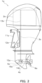
- FIG. 2 is a side view of the marine propulsion device 1a.
- the structure of the marine propulsion device 1a will be hereinafter explained; however, the structure of the marine propulsion device 1a is also true of the marine propulsion device 1b.
- the marine propulsion device 1a is attached to the watercraft 100 through a bracket 11a.
- the bracket 11a supports the marine propulsion device 1a such that the marine propulsion device 1a is rotatable about a steering shaft 12a.
- the marine propulsion device 1a includes a drive unit 2a, a drive shaft 3a, a propeller shaft 4a, and a shift mechanism 5a.
- the drive unit 2a is an internal combustion engine.
- the drive unit 2a includes a crankshaft 13a.
- the crankshaft 13a extends in the up-and-down direction of the marine propulsion device 1a.
- the drive shaft 3a is connected to the crankshaft 13a.
- the propeller shaft 4a extends in the back-and-forth direction of the marine propulsion device 1a.
- the propeller shaft 4a is connected to the drive shaft 3a through the shift mechanism 5a.
- a propeller 6a is attached to the propeller shaft 4a.
- the shift mechanism 5a includes a forward moving gear 14a, a rearward moving gear 15a, and a dog clutch 16a.
- a forward moving gear 14a, a rearward moving gear 15a When gear engagement of each gear 14a, 15a is switched by the dog clutch 16a, the shift mechanism 5a is switched among a forward moving state, a rearward moving state, and a neutral state.
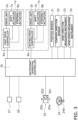
- FIG. 3 is a schematic diagram showing a configuration of a watercraft operating system for the watercraft 100.
- the marine propulsion device 1a includes a shift actuator 7a and a steering actuator 8a.
- the shift actuator 7a is connected to the dog clutch 16a of the shift mechanism 5a.
- the shift actuator 7a actuates the dog clutch 16a to switch gear engagement of each gear 14a, 15a.
- the shift mechanism 5a is switched among the forward moving state, the rearward moving state, and the neutral state.
- the shift actuator 7a is, for instance, an electric motor.
- the shift actuator 7a may be another type of actuator such as an electric cylinder, a hydraulic motor, or a hydraulic cylinder.
- the steering actuator 8a is connected to the marine propulsion device 1a.
- the steering actuator 8a rotates the marine propulsion device 1a about the steering shaft 12a. Accordingly, the marine propulsion device 1a is changed in rudder angle.
- the rudder angle refers to an angle of the propeller shaft 4a with respect to the back-and-forth direction of the marine propulsion device 1a.
- the steering actuator 8a is, for instance, an electric motor. However, the steering actuator 8a may be another type of actuator such as an electric cylinder, a hydraulic motor, or a hydraulic cylinder.
- the marine propulsion device 1a includes a first drive controller 9a.
- the first drive controller 9a includes a processor such as a CPU (Central Processing Unit) and memories such as a RAM (Random Access Memory) and a ROM (Read Only Memory).
- the first drive controller 9a stores programs and data for controlling the marine propulsion device 1a.
- the first drive controller 9a controls the drive unit 2a.
- the marine propulsion device 1b includes a drive unit 2b, a shift actuator 7b, a steering actuator 8b, and a second drive controller 9b.
- the drive unit 2b, the shift actuator 7b, the steering actuator 8b, and the second drive controller 9b in the marine propulsion device 1b are configured in similar manner to the drive unit 2a, the shift actuator 7a, the steering actuator 8a, and the first drive controller 9a in the marine propulsion device 1a, respectively.
- the watercraft operating system (or means) includes a steering wheel 24, an operating device 25, a first input device 27, and a second input device 28.
- the steering wheel 24, the operating device 25, the first input device 27, and the second input device 28 are disposed in a cockpit of the watercraft 100.
- the steering wheel 24, the operating device 25, the first input device 27, and the second input device 28 are manually operable.
- the steering wheel 24 is a device for allowing an operator to operate the turning direction of the watercraft 100.
- the steering wheel 24 includes a sensor 240.
- the sensor 240 outputs a steering signal indicating the operating direction and the operating amount of the steering wheel 24.
- the operating device 25 includes a first throttle lever 25a and a second throttle lever 25b.
- the first throttle lever 25a is a device for allowing the operator to regulate the magnitude of the thrust generated by the marine propulsion device 1a.
- the first throttle lever 25a is also a device for allowing the operator to switch the direction of the thrust generated by the marine propulsion device 1a between a forward moving direction and a rearward moving direction.
- the first throttle lever 25a is operable from a neutral position to a forward moving position and a rearward moving position.
- the neutral position is a position located between the forward moving position and the rearward moving position.
- the first throttle lever 25a includes a sensor 251.
- the sensor 251 outputs a throttle signal indicating the operating direction and the operating amount of the first throttle lever 25a.
- the second throttle lever 25b is a device for allowing the operator to regulate the magnitude of the thrust generated by the marine propulsion device 1b.
- the second throttle lever 25b is also a device for allowing the operator to switch the direction of the thrust generated by the marine propulsion device 1b between the forward moving direction and the rearward moving direction.
- the second throttle lever 25b is configured in similar manner to the first throttle lever 25a.
- the second throttle lever 25b includes a sensor 252.
- the sensor 252 outputs a throttle signal indicating the operating direction and the operating amount of the second throttle lever 25b.
- the watercraft operating system includes a watercraft operating controller 30.
- the watercraft operating controller 30 includes a processor such as a CPU and memories such as a RAM and a ROM.
- the watercraft operating controller 30 stores programs and data for controlling the marine propulsion devices 1a and 1b.
- the watercraft operating controller 30 is connected to the first and second drive controllers 9a and 9b through wired or wireless communication.
- the watercraft operating controller 30 is connected to the steering wheel 24, the operating device 25, the first input device 27, and the second input device 28 through wired or wireless communication.
- the watercraft operating controller 30 receives the steering signal from the sensor 240.
- the watercraft operating controller 30 receives the throttle signal from each sensor 251, 252.
- the watercraft operating controller 30 outputs command signals to the first and second drive controllers 9a and 9b based on the signals received from the sensors 240, 251, and 252.
- the command signal is transmitted to the shift actuator 7a and the steering actuator 8a through the first drive controller 9a.
- the command signal is transmitted to the shift actuator 7b and the steering actuator 8b through the second drive controller 9b.
- the watercraft operating controller 30 outputs a command signal for the shift actuator 7a depending on the operating direction of the first throttle lever 25a. In response, shifting between forward movement and rearward movement is performed by the marine propulsion device 1a.
- the watercraft operating controller 30 outputs a throttle command for the drive unit 2a depending on the operating amount of the first throttle lever 25a.
- the first drive controller 9a controls the output rotational speed of the marine propulsion device 1a in accordance with the throttle command.
- the watercraft operating controller 30 outputs a command signal for the shift actuator 7b depending on the operating direction of the second throttle lever 25b. In response, shifting between forward movement and rearward movement is performed by the marine propulsion device 1b.
- the watercraft operating controller 30 outputs a throttle command for the drive unit 2b depending on the operating amount of the second throttle lever 25b.
- the second drive controller 9b controls the output rotational speed of the marine propulsion device 1b in accordance with the throttle command.
- the watercraft operating controller 30 controls each steering actuator 8a, 8b such that each marine propulsion device 1a, 1b is rotated about the steering shaft 12a thereof depending on the operating direction and the operating amount of the steering wheel 24.
- the watercraft operating controller 30 controls the rudder angle of each marine propulsion device 1a, 1b depending on the operating amount of the steering wheel 24.
- the watercraft operating system includes a position sensor 31.
- the position sensor 31 detects the position of the watercraft 100.
- the position sensor 31 is a GNSS (Global Navigation Satellite System) receiver such as a GPS (Global Positioning System) receiver.
- GPS Global Positioning System
- the position sensor 31 may be a type of sensor other than the GNSS receiver.
- the position sensor 31 outputs a signal indicating the position of the watercraft 100.
- the watercraft operating controller 30 is connected to the position sensor 31 in communicable manner.
- the watercraft operating controller 30 obtains the position of the watercraft 100 based on the signal outputted thereto from the position sensor 31.
- the watercraft operating controller 30 obtains the speed of the watercraft 100 based on the signal outputted thereto from the position sensor 31.
- the watercraft operating system may include another type of sensor for detecting the speed over ground or the speed through water of the watercraft 100.
- the speed over ground refers to the speed of the watercraft 100 with respect to the ground
- the speed through water refers to the speed of the watercraft 100 with respect to water (seawater).
- the watercraft operating system includes a compass direction sensor 32.
- the compass direction sensor 32 detects the course of the watercraft 100.
- the compass direction sensor 32 is, for instance, an IMU (Inertial Measurement Unit). However, the compass direction sensor 32 may be a type of sensor other than the IMU.
- the watercraft operating controller 30 is connected to the compass direction sensor 32 in communicable manner. The watercraft operating controller 30 obtains the course of the watercraft 100 based on a signal outputted thereto from the compass direction sensor 32.
- the watercraft operating system includes a wind direction measuring instrument 33 and a wind speed measuring instrument 34.
- the wind direction measuring instrument 33 and the wind speed measuring instrument 34 output measurement results thereof to the watercraft operating controller 30.
- the watercraft operating controller 30 obtains a wind direction and a wind speed based on signals outputted thereto from the wind direction measuring instrument 33 and the wind speed measuring instrument 34.
- the wind direction measuring instrument 33 and the wind speed measuring instrument 34 may be omitted.
- the first input device 27 is disposed on, for instance, a watercraft operating device such as a joystick.
- the first input device 27 is operable by the operator to select one of control modes of each marine propulsion device 1a, 1b.
- the first input device 27 includes at least one switch for selecting one of the control modes.
- the first input device 27 may not necessarily include the at least one switch, and alternatively, may include another type of device such as a touchscreen.
- the first input device 27 outputs an operating signal indicating the control mode selected in accordance with the operation by the operator.
- the watercraft operating controller 30 receives the operating signal from the first input device 27.
- the watercraft operating controller 30 executes automated watercraft control for the watercraft 100 by controlling the rudder angle and the thrust of each marine propulsion device 1a, 1b in accordance with the selected control mode.
- the second input device 28 is operable by the operator to perform control mode setting.
- the second input device 28 is, for instance, a touchscreen.
- the second input device 28 is not limited to the touchscreen, and alternatively, may include another type of device such as at least one switch.
- the second input device 28 outputs an operating signal indicating the setting of the control mode selected by the operator.
- the watercraft operating controller 30 receives the operating signal from the second input device 28.
- the control modes include a first mode and a second mode.
- the watercraft operating controller 30 controls each marine propulsion device 1a, 1b such that the watercraft 100 is kept located in a target spot.
- the target spot is, for instance, the position of the watercraft 100 located when the first mode has been selected by the first input device 27.
- the watercraft operating controller 30 controls each marine propulsion device 1a, 1b such that the watercraft 100 is kept located in the position thereof located at a point of time when the operating signal, indicating the first mode, has been received by the watercraft operating controller 30.
- the watercraft operating controller 30 controls each marine propulsion device 1a, 1b such that the watercraft 100 is kept located in the target spot, while the bow of the watercraft 100 is kept oriented in a target compass direction.
- the target spot and the target compass direction are, for instance, the position and the compass direction of the watercraft 100 located and oriented when the second mode has been selected by the first input device 27.
- the watercraft operating controller 30 controls each marine propulsion device 1a, 1b such that the watercraft 100 is kept located in the target spot (P0), while being kept oriented in the compass direction thereof oriented at a point of time when the operating signal, indicating the second mode, has been received by the watercraft operating controller 30.
- the second mode is a mode including transverse movement of the watercraft 100 in a low-speed range. It should be noted that the target compass direction may be arbitrarily set by the operator using the second input device 28.
- the watercraft operating controller 30 selects in which of a bow mode and a stern mode each marine propulsion device 1a, 1b should be controlled depending on the position of the target spot P0 with respect to the first spot P1 and controls each marine propulsion device 1a, 1b in the selected mode such that the watercraft 100 is moved from the first spot P1 to the target spot P0.
- FIG. 4 is a diagram showing a series of motions performed by the watercraft 100 when the bow mode is selected.
- the bow mode is a mode which the watercraft 100 is moved to the target spot P0 with the bow of the watercraft 100 facing the target spot P0.
- a Cartesian coordinate system with x- and y-axes is herein assumed.
- the center of gravity of the watercraft 100 is set as the origin of the Cartesian coordinate system; the x-and y-axes divide the coordinate plane into four quadrants defined as first to fourth quadrants.
- the watercraft operating controller 30 selects the bow mode.
- the target spot P0 is located in the first quadrant.
- the y-axis is an axis that passes through the center of gravity of the watercraft 100, the middle of the bow of the watercraft 100, and the middle of the stern of the watercraft 100.
- the x-axis is an axis that passes through the center of gravity of the watercraft 100 and is perpendicular to the y-axis.
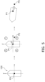
- the stern mode is a mode in which the watercraft 100 is moved from the stern of the watercraft 100 to the target spot P0 with the stern of the watercraft 100 facing the target spot P0.
- the watercraft operating controller 30 selects the stern mode.
- the target spot P0 is located in the fourth quadrant.
- a determination regarding in which of the first to fourth quadrants the target spot P0 is located is made based on, for instance, difference in angle ⁇ between the compass direction from the first spot P1 to the target spot P0 and the compass direction of the bow of the watercraft 100 located in the first spot P1.
- difference in angle ⁇ is an acute angle
- the first spot P1 is supposed to be located in the first or second quadrant; hence, the watercraft operating controller 30 selects the bow mode.
- the difference in angle ⁇ is an obtuse angle
- the first spot P1 is supposed to be located in the third or fourth quadrant; hence, the watercraft operating controller 30 selects the stern mode.
- the watercraft operating controller 30 determines whether or not the watercraft 100 is remote from the target spot P0 by a predetermined distance or greater. In other words, the watercraft operating controller 30 determines whether or not the distance to the target spot P0 from the present position of the watercraft 100 is a predetermined threshold or greater. When the distance to the target spot P0 from the present position of the watercraft 100 is the predetermined threshold or greater, the watercraft operating controller 30 selects in which of the bow mode and the stern mode each marine propulsion device 1a, 1b should be controlled and controls each marine propulsion device 1a, 1b in the selected mode such that the watercraft 100 is moved from the present position to the target spot P0.
- the watercraft operating controller 30 determines whether or not the turning speed of the watercraft 100 is a predetermined speed or less. When the turning speed of the watercraft 100 is the predetermined speed or less, the watercraft operating controller 30 switches the bow mode into the stern mode and controls each marine propulsion device 1a, 1b in the stern mode.
- the watercraft operating controller 30 determines whether or not the turning speed of the watercraft 100 is the predetermined speed or less. When the turning speed of the watercraft 100 is the predetermined speed or less, the watercraft operating controller 30 switches the stern mode into the bow mode and controls each marine propulsion device 1a, 1b in the bow mode.
- the watercraft 100 receives wind W blowing from the northeast.
- the watercraft 100 is more likely to be affected and moved by the wind W at the bow than at the stern; hence, the watercraft 100 is swept, while spinning counterclockwise.
- the target spot P0 is located in the first quadrant; hence, the watercraft operating controller 30 selects the bow mode and controls each marine propulsion device 1a, 1b such that the watercraft 100 turns clockwise.
- the watercraft operating controller 30 switches the bow mode into the stern mode and controls each marine propulsion device 1a, 1b in the stern mode.
- the watercraft operating controller 30 selects the stern mode and controls each marine propulsion device 1a, 1b such that the watercraft 100 turns clockwise.
- the wind W blowing from the northeast acts on the watercraft 100 so as to spin the watercraft 100 counterclockwise; hence, chances are that the turning speed gets slow and the stern of the watercraft 100 cannot be oriented to the target spot P0 even after elapse of the predetermined period of time. Because of this, when the turning speed of the watercraft 100 is the predetermined speed or less, the watercraft operating controller 30 switches the stern mode into the bow mode and controls each marine propulsion device 1a, 1b in the bow mode.
- the watercraft operating controller 30 determines whether or not the speed through water of the watercraft 100 is a predetermined speed or less. When the speed through water of the watercraft 100 is the predetermined speed or less in the first mode, the watercraft operating controller 30 switches the first mode into the second mode and controls each marine propulsion device 1a, 1b in the second mode. When switching the first mode into the second mode depending on the speed through water of the watercraft 100, the watercraft operating controller 30 controls each marine propulsion device 1a, 1b, for instance, such that the watercraft 100 is kept located in the target spot P0, while being kept oriented in the compass direction thereof oriented when the first mode has been switched into the second mode.
- the predetermined speed is, for instance, a speed enough to keep the position and the compass direction of the watercraft 100 by idling of each marine propulsion device 1a, 1b in the second mode.
- the watercraft operating controller 30 may control each marine propulsion device 1a, 1b such that the watercraft 100 is kept located in the target spot P0, while being kept oriented in the compass direction thereof oriented when the first mode has been selected by the first input device 27.
- the watercraft operating controller 30 may inform an operator of this switching through a touchscreen or an informing device.
- the watercraft operating controller 30 determines whether or not the watercraft 100 is remote from the target spot P0 by a predetermined distance or greater. In other words, after switching the first mode into the second mode, the watercraft operating controller 30 determines whether or not the distance to the target spot P0 from the present position of the watercraft 100 is a predetermined threshold or greater. When the distance to the target spot P0 from the present position of the watercraft 100 is the predetermined threshold or greater, it is difficult to keep the position and the compass direction of the watercraft 100 in the second mode; hence, the watercraft operating controller 30 switches the second mode into the first mode and controls each marine propulsion device 1a, 1b in the first mode. When switching the second mode into the first mode, the watercraft operating controller 30 may inform the operator of this switching through the touchscreen or the informing device.
- the watercraft operating controller 30 selects in which of the bow mode and the stern mode each marine propulsion device 1a, 1b should be controlled depending on the position of the target spot P0 with respect to the first spot P1. Accordingly, the watercraft 100 can be efficiently moved to approach the target spot P0; hence, the watercraft 100 can be easily kept located in the target spot P0.
- the first mode is switched into the second mode depending on the speed through water of the watercraft 100
- the second mode is switched into the first mode depending on the distance to the target spot P0 from the present position of the watercraft 100; hence, among the control modes, suitable one for the condition of the watercraft 100 can be automatically selected.
- Each marine propulsion device is not limited to the outboard motor, and alternatively, may be another type of propulsion device such as an inboard engine outboard drive or a jet propulsion device.
- the structure of each marine propulsion device is not limited to that in the preferred embodiment described above and may be changed.
- each drive unit 2a, 2b is not limited to the internal combustion engine, and alternatively, may be an electric motor.
- each drive unit 2a, 2b may be a hybrid system of an internal combustion engine and an electric motor.
- the number of marine propulsion devices is not limited to two. The number of marine propulsion devices may be more than two.
- the watercraft operating controller 30 is configured to select either the bow mode or the stern mode under selection of the first mode based on difference in angle ⁇ between the direction from the first spot P1 to the target spot P0 and the compass direction of the bow of the watercraft 100 located in the first spot P1. However, the watercraft operating controller 30 may select either the bow mode or the stern mode depending on the wind direction and the wind speed. Alternatively, the watercraft operating controller 30 may select either the bow mode or the stern mode depending on the difference in angle ⁇ and both the wind direction and the wind speed.
- a length of time required to achieve orientation toward the target spot P0 may be calculated depending on at least either the difference in angle ⁇ or both the wind direction and the wind speed; then, the watercraft operating controller 30 may be configured to select one shorter in length of time required to achieve orientation toward the target spot P0 than the other from the bow mode and the stern mode.
- the first mode may further include a compass direction keeping mode for keeping the compass direction of the watercraft 100.
- the compass direction keeping mode is identical to the control mode to be executed in the second mode. Specifically, when it is intended to move the watercraft 100 from the first spot P1 to the target spot P0 under selection of the first mode, a selection may be made regarding in which of the bow mode, the stern mode, and the compass direction keeping mode each marine propulsion device 1a, 1b should be controlled depending on the position of the target spot P0 with respect to the first spot P1.
- the watercraft operating controller 30 may select the compass direction keeping mode when the distance to the target spot P0 from the present position of the watercraft 100 is less than a predetermined threshold.
- the watercraft operating controller 30 is configured to switch the first mode into the second mode depending on the speed through water of the watercraft 100; however, the watercraft operating controller 30 may switch the first mode into the second mode when the number of revolutions of the drive unit 2a, cumulated from the onset of controlling the watercraft 100 in the first mode, is a predetermined value or less and simultaneously the speed of the watercraft 100 approaching the target spot P0 is greater than a predetermined speed.
Landscapes
- Engineering & Computer Science (AREA)
- Chemical & Material Sciences (AREA)
- Combustion & Propulsion (AREA)
- Mechanical Engineering (AREA)
- Ocean & Marine Engineering (AREA)
- Radar, Positioning & Navigation (AREA)
- Aviation & Aerospace Engineering (AREA)
- Remote Sensing (AREA)
- Physics & Mathematics (AREA)
- General Physics & Mathematics (AREA)
- Automation & Control Theory (AREA)
- Control Of Vehicle Engines Or Engines For Specific Uses (AREA)
- Control Of Position, Course, Altitude, Or Attitude Of Moving Bodies (AREA)
Abstract
Description
- The present invention relates to a system (or means) for and a method of controlling a watercraft.
- There has been conventionally known a type of system for automatically controlling a watercraft such that the watercraft moves toward a specified target spot. For example, a system described in
JP 2015-66979 A - As a type of automated control for watercraft, there has been also conventionally known a keeping control for keeping a watercraft located in a target spot. When the watercraft is remote from the target spot under the conventional keeping control, an outboard motor is controlled to move the watercraft to the target spot in either a bow mode or a stern mode preliminarily set by a user. The bow mode serves to direct the bow of the watercraft to the target spot, whereas the stern mode serves to direct the stern of the watercraft to the target spot.
- When the watercraft is remote from the target spot under the conventional keeping control, the outboard motor is controlled to move the watercraft to the target spot in either the bow mode or the stern mode preliminarily set by the user. Because of this, chances are that, when the watercraft is remote from the target spot, it takes time for the watercraft to move to the target spot depending on the position of the watercraft; hence, there is still room for improvement for the conventional keeping control. It is an object of the present invention to provide a system and a method, whereby a watercraft can be easily kept located in a target spot under an automated control. According to the present invention said object is solved by system for controlling a watercraft having the features of
independent claim 1. Moreover, according to the present invention said object is solved by a method of controlling a watercraft having the features of independent claim 11. Preferred embodiments are laid down in the dependent claims. - A system (or means) according to an aspect of the present disclosure relates to a system for controlling a watercraft and includes a marine propulsion device, an input device, and a controller. The input device is configured to output an operating signal indicating a first mode selected in accordance with an operation thereof. The controller receives the operating signal. The controller controls the marine propulsion device such that the watercraft is kept located in a target spot under selection of the first mode. When it is intended to move the watercraft to the target spot from a first spot remote from the target spot under selection of the first mode, the controller selects in which of modes, composed of a bow mode orienting a bow of the watercraft toward the target spot and a stern mode orienting a stern of the watercraft toward the target spot, the marine propulsion device is controlled depending on a position of the target spot with respect to the first spot so as to control the marine propulsion device such that the watercraft is moved from the first spot to the target spot in one selected from the bow mode and the stern mode.
- A system according to another aspect of the present disclosure relates to a system for controlling a watercraft and includes a marine propulsion device, an input device, and a controller. The input device is configured to output an operating signal indicating a first mode selected in accordance with an operation thereof. The controller receives the operating signal. The controller controls the marine propulsion device such that the watercraft is kept located in a target spot under selection of the first mode. When it is intended to move the watercraft to the target spot from a first spot remote from the target spot under selection of the first mode, the controller selects in which of modes, composed of a bow mode orienting a bow of the watercraft toward the target spot, a stern mode orienting a stern of the watercraft toward the target spot, and a compass direction keeping mode keeping constant a compass direction of the watercraft, the marine propulsion device is controlled depending on a position of the target spot with respect to the first spot so as to control the marine propulsion device such that the watercraft is moved from the first spot to the target spot in one selected from the bow mode, the stern mode, and the compass direction keeping mode.
- A method according to yet another aspect of the present disclosure relates to a method of controlling a watercraft including a marine propulsion device and an input device and includes the following processes. The first process relates to receiving an operating signal indicating a first mode selected in accordance with an operation of the input device. The second process relates to controlling the marine propulsion device such that the watercraft is kept located in a target spot under selection of the first mode. The third process is executed when it is intended to move the watercraft to the target spot from a first spot remote from the target spot under selection of the first mode and relates to selecting in which of modes, composed of a bow mode orienting a bow of the watercraft toward the target spot and a stern mode orienting a stern of the watercraft toward the target spot, the marine propulsion device is controlled depending on a position of the target spot with respect to the first spot so as to control the marine propulsion device such that the watercraft is moved from the first spot to the target spot in one selected from the bow mode and the stern mode.
- A method according to still another aspect of the present disclosure relates to a method of controlling a watercraft including a marine propulsion device and an input device and includes the following processes. The first process relates to receiving an operating signal indicating a first mode selected in accordance with an operation of the input device. The second process relates to controlling the marine propulsion device such that the watercraft is kept located in a target spot under selection of the first mode. The third process is executed when it is intended to move the watercraft to the target spot from a first spot remote from the target spot under selection of the first mode and relates to selecting in which of modes, composed of a bow mode orienting a bow of the watercraft toward the target spot, a stern mode orienting a stern of the watercraft toward the target spot, and a compass direction keeping mode keeping constant a compass direction of the watercraft, the marine propulsion device is controlled depending on a position of the target spot with respect to the first spot so as to control the marine propulsion device such that the watercraft is moved from the first spot to the target spot in one selected from the bow mode, the stern mode, and the compass direction keeping mode.
- In the system and the method according to the present disclosure, when it is intended to move the watercraft from the first spot to the target spot under selection of the first mode for controlling the marine propulsion device such that the watercraft is kept located in the target spot, the controller selects either in which of the bow mode and the stern mode or in which of the bow mode, the stern mode, and the compass direction keeping mode the marine propulsion device is controlled depending on the position of the target spot with respect to the first spot. Accordingly, the watercraft can be efficiently moved to approach the target spot; hence, the watercraft can be easily kept located in the target spot.
- Overall, according to the present disclosure, it is possible to provide a system and a method whereby a watercraft can be easily kept located in a target spot under automated control.
-
-
FIG. 1 is a perspective view of a watercraft to which marine propulsion devices according to a preferred embodiment are mounted. -
FIG. 2 is a side view of a marine propulsion device. -
FIG. 3 is a schematic diagram showing a configuration of a watercraft operating system. -
FIG. 4 is a diagram showing a series of motions performed by the watercraft when a bow mode is selected in a first control mode. -
FIG. 5 is a diagram showing a series of motions performed by the watercraft when a stern mode is selected in the first control mode. -
FIG. 6 is a diagram showing a series of motions performed by the watercraft in the first control mode. -
FIG. 7 is a diagram showing a series of motions performed by the watercraft in the first control mode. - A preferred embodiment will be hereinafter explained with reference to drawings.
FIG. 1 is a perspective view of awatercraft 100 to whichmarine propulsion devices marine propulsion devices watercraft 100 as a plurality of marine propulsion devices. In the present preferred embodiment, themarine propulsion devices marine propulsion devices watercraft 100. Themarine propulsion devices watercraft 100. Eachmarine propulsion device watercraft 100. -
FIG. 2 is a side view of themarine propulsion device 1a. The structure of themarine propulsion device 1a will be hereinafter explained; however, the structure of themarine propulsion device 1a is also true of themarine propulsion device 1b. Themarine propulsion device 1a is attached to thewatercraft 100 through abracket 11a. Thebracket 11a supports themarine propulsion device 1a such that themarine propulsion device 1a is rotatable about asteering shaft 12a. - The
marine propulsion device 1a includes adrive unit 2a, adrive shaft 3a, apropeller shaft 4a, and ashift mechanism 5a. Thedrive unit 2a is an internal combustion engine. Thedrive unit 2a includes acrankshaft 13a. Thecrankshaft 13a extends in the up-and-down direction of themarine propulsion device 1a. Thedrive shaft 3a is connected to thecrankshaft 13a. Thepropeller shaft 4a extends in the back-and-forth direction of themarine propulsion device 1a. Thepropeller shaft 4a is connected to thedrive shaft 3a through theshift mechanism 5a. Apropeller 6a is attached to thepropeller shaft 4a. - The
shift mechanism 5a includes a forward moving gear 14a, a rearward movinggear 15a, and adog clutch 16a. When gear engagement of eachgear 14a, 15a is switched by thedog clutch 16a, theshift mechanism 5a is switched among a forward moving state, a rearward moving state, and a neutral state. -
FIG. 3 is a schematic diagram showing a configuration of a watercraft operating system for thewatercraft 100. As shown inFIG. 3 , themarine propulsion device 1a includes ashift actuator 7a and asteering actuator 8a. - The
shift actuator 7a is connected to the dog clutch 16a of theshift mechanism 5a. Theshift actuator 7a actuates the dog clutch 16a to switch gear engagement of eachgear 14a, 15a. In response, theshift mechanism 5a is switched among the forward moving state, the rearward moving state, and the neutral state. Theshift actuator 7a is, for instance, an electric motor. However, theshift actuator 7a may be another type of actuator such as an electric cylinder, a hydraulic motor, or a hydraulic cylinder. - The
steering actuator 8a is connected to themarine propulsion device 1a. Thesteering actuator 8a rotates themarine propulsion device 1a about thesteering shaft 12a. Accordingly, themarine propulsion device 1a is changed in rudder angle. The rudder angle refers to an angle of thepropeller shaft 4a with respect to the back-and-forth direction of themarine propulsion device 1a. Thesteering actuator 8a is, for instance, an electric motor. However, thesteering actuator 8a may be another type of actuator such as an electric cylinder, a hydraulic motor, or a hydraulic cylinder. - The
marine propulsion device 1a includes afirst drive controller 9a. Thefirst drive controller 9a includes a processor such as a CPU (Central Processing Unit) and memories such as a RAM (Random Access Memory) and a ROM (Read Only Memory). Thefirst drive controller 9a stores programs and data for controlling themarine propulsion device 1a. Thefirst drive controller 9a controls thedrive unit 2a. - The
marine propulsion device 1b includes adrive unit 2b, ashift actuator 7b, asteering actuator 8b, and asecond drive controller 9b. Thedrive unit 2b, theshift actuator 7b, thesteering actuator 8b, and thesecond drive controller 9b in themarine propulsion device 1b are configured in similar manner to thedrive unit 2a, theshift actuator 7a, thesteering actuator 8a, and thefirst drive controller 9a in themarine propulsion device 1a, respectively. - The watercraft operating system (or means) includes a
steering wheel 24, an operatingdevice 25, afirst input device 27, and asecond input device 28. Thesteering wheel 24, the operatingdevice 25, thefirst input device 27, and thesecond input device 28 are disposed in a cockpit of thewatercraft 100. Thesteering wheel 24, the operatingdevice 25, thefirst input device 27, and thesecond input device 28 are manually operable. - The
steering wheel 24 is a device for allowing an operator to operate the turning direction of thewatercraft 100. Thesteering wheel 24 includes asensor 240. Thesensor 240 outputs a steering signal indicating the operating direction and the operating amount of thesteering wheel 24. - The operating
device 25 includes afirst throttle lever 25a and asecond throttle lever 25b. Thefirst throttle lever 25a is a device for allowing the operator to regulate the magnitude of the thrust generated by themarine propulsion device 1a. Thefirst throttle lever 25a is also a device for allowing the operator to switch the direction of the thrust generated by themarine propulsion device 1a between a forward moving direction and a rearward moving direction. Thefirst throttle lever 25a is operable from a neutral position to a forward moving position and a rearward moving position. The neutral position is a position located between the forward moving position and the rearward moving position. Thefirst throttle lever 25a includes asensor 251. Thesensor 251 outputs a throttle signal indicating the operating direction and the operating amount of thefirst throttle lever 25a. - The
second throttle lever 25b is a device for allowing the operator to regulate the magnitude of the thrust generated by themarine propulsion device 1b. Thesecond throttle lever 25b is also a device for allowing the operator to switch the direction of the thrust generated by themarine propulsion device 1b between the forward moving direction and the rearward moving direction. Thesecond throttle lever 25b is configured in similar manner to thefirst throttle lever 25a. Thesecond throttle lever 25b includes asensor 252. Thesensor 252 outputs a throttle signal indicating the operating direction and the operating amount of thesecond throttle lever 25b. - The watercraft operating system includes a
watercraft operating controller 30. Thewatercraft operating controller 30 includes a processor such as a CPU and memories such as a RAM and a ROM. Thewatercraft operating controller 30 stores programs and data for controlling themarine propulsion devices watercraft operating controller 30 is connected to the first andsecond drive controllers watercraft operating controller 30 is connected to thesteering wheel 24, the operatingdevice 25, thefirst input device 27, and thesecond input device 28 through wired or wireless communication. - The
watercraft operating controller 30 receives the steering signal from thesensor 240. Thewatercraft operating controller 30 receives the throttle signal from eachsensor watercraft operating controller 30 outputs command signals to the first andsecond drive controllers sensors shift actuator 7a and thesteering actuator 8a through thefirst drive controller 9a. The command signal is transmitted to theshift actuator 7b and thesteering actuator 8b through thesecond drive controller 9b. - For example, the
watercraft operating controller 30 outputs a command signal for theshift actuator 7a depending on the operating direction of thefirst throttle lever 25a. In response, shifting between forward movement and rearward movement is performed by themarine propulsion device 1a. Thewatercraft operating controller 30 outputs a throttle command for thedrive unit 2a depending on the operating amount of thefirst throttle lever 25a. Thefirst drive controller 9a controls the output rotational speed of themarine propulsion device 1a in accordance with the throttle command. - The
watercraft operating controller 30 outputs a command signal for theshift actuator 7b depending on the operating direction of thesecond throttle lever 25b. In response, shifting between forward movement and rearward movement is performed by themarine propulsion device 1b. Thewatercraft operating controller 30 outputs a throttle command for thedrive unit 2b depending on the operating amount of thesecond throttle lever 25b. Thesecond drive controller 9b controls the output rotational speed of themarine propulsion device 1b in accordance with the throttle command. - The
watercraft operating controller 30 controls each steeringactuator marine propulsion device steering shaft 12a thereof depending on the operating direction and the operating amount of thesteering wheel 24. Thewatercraft operating controller 30 controls the rudder angle of eachmarine propulsion device steering wheel 24. - The watercraft operating system includes a
position sensor 31. Theposition sensor 31 detects the position of thewatercraft 100. Theposition sensor 31 is a GNSS (Global Navigation Satellite System) receiver such as a GPS (Global Positioning System) receiver. However, theposition sensor 31 may be a type of sensor other than the GNSS receiver. Theposition sensor 31 outputs a signal indicating the position of thewatercraft 100. Thewatercraft operating controller 30 is connected to theposition sensor 31 in communicable manner. Thewatercraft operating controller 30 obtains the position of thewatercraft 100 based on the signal outputted thereto from theposition sensor 31. Besides, thewatercraft operating controller 30 obtains the speed of thewatercraft 100 based on the signal outputted thereto from theposition sensor 31. The watercraft operating system may include another type of sensor for detecting the speed over ground or the speed through water of thewatercraft 100. The speed over ground refers to the speed of thewatercraft 100 with respect to the ground, whereas the speed through water refers to the speed of thewatercraft 100 with respect to water (seawater). - The watercraft operating system includes a
compass direction sensor 32. Thecompass direction sensor 32 detects the course of thewatercraft 100. Thecompass direction sensor 32 is, for instance, an IMU (Inertial Measurement Unit). However, thecompass direction sensor 32 may be a type of sensor other than the IMU. Thewatercraft operating controller 30 is connected to thecompass direction sensor 32 in communicable manner. Thewatercraft operating controller 30 obtains the course of thewatercraft 100 based on a signal outputted thereto from thecompass direction sensor 32. - The watercraft operating system includes a wind
direction measuring instrument 33 and a windspeed measuring instrument 34. The winddirection measuring instrument 33 and the windspeed measuring instrument 34 output measurement results thereof to thewatercraft operating controller 30. Thewatercraft operating controller 30 obtains a wind direction and a wind speed based on signals outputted thereto from the winddirection measuring instrument 33 and the windspeed measuring instrument 34. In the present preferred embodiment, the winddirection measuring instrument 33 and the windspeed measuring instrument 34 may be omitted. - The
first input device 27 is disposed on, for instance, a watercraft operating device such as a joystick. Thefirst input device 27 is operable by the operator to select one of control modes of eachmarine propulsion device first input device 27 includes at least one switch for selecting one of the control modes. Thefirst input device 27 may not necessarily include the at least one switch, and alternatively, may include another type of device such as a touchscreen. Thefirst input device 27 outputs an operating signal indicating the control mode selected in accordance with the operation by the operator. - The
watercraft operating controller 30 receives the operating signal from thefirst input device 27. Thewatercraft operating controller 30 executes automated watercraft control for thewatercraft 100 by controlling the rudder angle and the thrust of eachmarine propulsion device - The
second input device 28 is operable by the operator to perform control mode setting. Thesecond input device 28 is, for instance, a touchscreen. Thesecond input device 28 is not limited to the touchscreen, and alternatively, may include another type of device such as at least one switch. Thesecond input device 28 outputs an operating signal indicating the setting of the control mode selected by the operator. Thewatercraft operating controller 30 receives the operating signal from thesecond input device 28. - The control modes include a first mode and a second mode. In the first mode, the
watercraft operating controller 30 controls eachmarine propulsion device watercraft 100 is kept located in a target spot. The target spot is, for instance, the position of thewatercraft 100 located when the first mode has been selected by thefirst input device 27. In other words, thewatercraft operating controller 30 controls eachmarine propulsion device watercraft 100 is kept located in the position thereof located at a point of time when the operating signal, indicating the first mode, has been received by thewatercraft operating controller 30. - In the second mode, the
watercraft operating controller 30 controls eachmarine propulsion device watercraft 100 is kept located in the target spot, while the bow of thewatercraft 100 is kept oriented in a target compass direction. In the second mode, the target spot and the target compass direction are, for instance, the position and the compass direction of thewatercraft 100 located and oriented when the second mode has been selected by thefirst input device 27. In other words, thewatercraft operating controller 30 controls eachmarine propulsion device watercraft 100 is kept located in the target spot (P0), while being kept oriented in the compass direction thereof oriented at a point of time when the operating signal, indicating the second mode, has been received by thewatercraft operating controller 30. The second mode is a mode including transverse movement of thewatercraft 100 in a low-speed range. It should be noted that the target compass direction may be arbitrarily set by the operator using thesecond input device 28. - As shown in
FIGS. 4 and5 , when it is intended to move thewatercraft 100 to the target spot P0 from a first spot P1 (the present position of the watercraft 100) remote from the target spot P0 under selection of the first mode, thewatercraft operating controller 30 selects in which of a bow mode and a stern mode eachmarine propulsion device marine propulsion device watercraft 100 is moved from the first spot P1 to the target spot P0. -
FIG. 4 is a diagram showing a series of motions performed by thewatercraft 100 when the bow mode is selected. The bow mode is a mode which thewatercraft 100 is moved to the target spot P0 with the bow of thewatercraft 100 facing the target spot P0. For example, a Cartesian coordinate system with x- and y-axes is herein assumed. The center of gravity of thewatercraft 100 is set as the origin of the Cartesian coordinate system; the x-and y-axes divide the coordinate plane into four quadrants defined as first to fourth quadrants. When the target spot P0 is located in the first or second quadrant, thewatercraft operating controller 30 selects the bow mode. InFIG. 4 , the target spot P0 is located in the first quadrant. The y-axis is an axis that passes through the center of gravity of thewatercraft 100, the middle of the bow of thewatercraft 100, and the middle of the stern of thewatercraft 100. The x-axis is an axis that passes through the center of gravity of thewatercraft 100 and is perpendicular to the y-axis. - As shown in
FIG. 5 , the stern mode is a mode in which thewatercraft 100 is moved from the stern of thewatercraft 100 to the target spot P0 with the stern of thewatercraft 100 facing the target spot P0. When the target spot P0 is located in the third or fourth quadrant, thewatercraft operating controller 30 selects the stern mode. InFIG. 5 , the target spot P0 is located in the fourth quadrant. - A determination regarding in which of the first to fourth quadrants the target spot P0 is located is made based on, for instance, difference in angle α between the compass direction from the first spot P1 to the target spot P0 and the compass direction of the bow of the
watercraft 100 located in the first spot P1. As shown inFIG. 4 , when the difference in angle α is an acute angle, the first spot P1 is supposed to be located in the first or second quadrant; hence, thewatercraft operating controller 30 selects the bow mode. As shown inFIG. 5 , when the difference in angle α is an obtuse angle, the first spot P1 is supposed to be located in the third or fourth quadrant; hence, thewatercraft operating controller 30 selects the stern mode. - In the first mode, the
watercraft operating controller 30 determines whether or not thewatercraft 100 is remote from the target spot P0 by a predetermined distance or greater. In other words, thewatercraft operating controller 30 determines whether or not the distance to the target spot P0 from the present position of thewatercraft 100 is a predetermined threshold or greater. When the distance to the target spot P0 from the present position of thewatercraft 100 is the predetermined threshold or greater, thewatercraft operating controller 30 selects in which of the bow mode and the stern mode eachmarine propulsion device marine propulsion device watercraft 100 is moved from the present position to the target spot P0. - When controlling each
marine propulsion device watercraft 100 is oriented toward the target spot P0 by selecting the bow mode under selection of the first mode, thewatercraft operating controller 30 determines whether or not the turning speed of thewatercraft 100 is a predetermined speed or less. When the turning speed of thewatercraft 100 is the predetermined speed or less, thewatercraft operating controller 30 switches the bow mode into the stern mode and controls eachmarine propulsion device - When controlling each
marine propulsion device watercraft 100 is oriented toward the target spot P0 by selecting the stern mode under selection of the first mode, thewatercraft operating controller 30 determines whether or not the turning speed of thewatercraft 100 is the predetermined speed or less. When the turning speed of thewatercraft 100 is the predetermined speed or less, thewatercraft operating controller 30 switches the stern mode into the bow mode and controls eachmarine propulsion device - Specifically, as shown in
FIG. 6 , chances are that thewatercraft 100 is swept, while spinning, from the target spot P0 by the effect of wind or tide. In the example shown inFIG. 6 , thewatercraft 100 receives wind W blowing from the northeast. In other words, thewatercraft 100 is more likely to be affected and moved by the wind W at the bow than at the stern; hence, thewatercraft 100 is swept, while spinning counterclockwise. In this case, the target spot P0 is located in the first quadrant; hence, thewatercraft operating controller 30 selects the bow mode and controls eachmarine propulsion device watercraft 100 turns clockwise. However, the wind W blowing from the northeast acts on thewatercraft 100 so as to spin thewatercraft 100 counterclockwise; hence, chances are that the turning speed gets slow and the bow of thewatercraft 100 cannot be oriented to the target spot P0 even after elapse of a predetermined period of time. Because of this, when the turning speed of thewatercraft 100 is the predetermined speed or less, thewatercraft operating controller 30 switches the bow mode into the stern mode and controls eachmarine propulsion device - As shown in
FIG. 7 , chances are that thewatercraft 100 is swept from the target spot P0, while spinning counterclockwise, by receiving the wind W blowing from the northeast and tide T flowing from the southwest. In the example shown inFIG. 7 , the target spot P0 is located in the third quadrant; hence, thewatercraft operating controller 30 selects the stern mode and controls eachmarine propulsion device watercraft 100 turns clockwise. However, the wind W blowing from the northeast acts on thewatercraft 100 so as to spin thewatercraft 100 counterclockwise; hence, chances are that the turning speed gets slow and the stern of thewatercraft 100 cannot be oriented to the target spot P0 even after elapse of the predetermined period of time. Because of this, when the turning speed of thewatercraft 100 is the predetermined speed or less, thewatercraft operating controller 30 switches the stern mode into the bow mode and controls eachmarine propulsion device - In the first mode, the
watercraft operating controller 30 determines whether or not the speed through water of thewatercraft 100 is a predetermined speed or less. When the speed through water of thewatercraft 100 is the predetermined speed or less in the first mode, thewatercraft operating controller 30 switches the first mode into the second mode and controls eachmarine propulsion device watercraft 100, thewatercraft operating controller 30 controls eachmarine propulsion device watercraft 100 is kept located in the target spot P0, while being kept oriented in the compass direction thereof oriented when the first mode has been switched into the second mode. The predetermined speed is, for instance, a speed enough to keep the position and the compass direction of thewatercraft 100 by idling of eachmarine propulsion device - It should be noted that when switching the first mode into the second mode depending on the speed through water of the
watercraft 100, thewatercraft operating controller 30 may control eachmarine propulsion device watercraft 100 is kept located in the target spot P0, while being kept oriented in the compass direction thereof oriented when the first mode has been selected by thefirst input device 27. When switching the first mode into the second mode, thewatercraft operating controller 30 may inform an operator of this switching through a touchscreen or an informing device. - After switching the first mode into the second mode, the
watercraft operating controller 30 determines whether or not thewatercraft 100 is remote from the target spot P0 by a predetermined distance or greater. In other words, after switching the first mode into the second mode, thewatercraft operating controller 30 determines whether or not the distance to the target spot P0 from the present position of thewatercraft 100 is a predetermined threshold or greater. When the distance to the target spot P0 from the present position of thewatercraft 100 is the predetermined threshold or greater, it is difficult to keep the position and the compass direction of thewatercraft 100 in the second mode; hence, thewatercraft operating controller 30 switches the second mode into the first mode and controls eachmarine propulsion device watercraft operating controller 30 may inform the operator of this switching through the touchscreen or the informing device. - In the watercraft operating system according to the present preferred embodiment explained above, when it is intended to move the
watercraft 100 from the first spot P1 to the target spot P0 under selection of the first mode for controlling eachmarine propulsion device watercraft 100 is kept located in the target spot P0, thewatercraft operating controller 30 selects in which of the bow mode and the stern mode eachmarine propulsion device watercraft 100 can be efficiently moved to approach the target spot P0; hence, thewatercraft 100 can be easily kept located in the target spot P0. - Besides, the first mode is switched into the second mode depending on the speed through water of the
watercraft 100, whereas the second mode is switched into the first mode depending on the distance to the target spot P0 from the present position of thewatercraft 100; hence, among the control modes, suitable one for the condition of thewatercraft 100 can be automatically selected. - Each marine propulsion device is not limited to the outboard motor, and alternatively, may be another type of propulsion device such as an inboard engine outboard drive or a jet propulsion device. The structure of each marine propulsion device is not limited to that in the preferred embodiment described above and may be changed. For example, each
drive unit drive unit - The
watercraft operating controller 30 is configured to select either the bow mode or the stern mode under selection of the first mode based on difference in angle α between the direction from the first spot P1 to the target spot P0 and the compass direction of the bow of thewatercraft 100 located in the first spot P1. However, thewatercraft operating controller 30 may select either the bow mode or the stern mode depending on the wind direction and the wind speed. Alternatively, thewatercraft operating controller 30 may select either the bow mode or the stern mode depending on the difference in angle α and both the wind direction and the wind speed. Yet alternatively, with respect to both the bow mode and the stern mode, a length of time required to achieve orientation toward the target spot P0 may be calculated depending on at least either the difference in angle α or both the wind direction and the wind speed; then, thewatercraft operating controller 30 may be configured to select one shorter in length of time required to achieve orientation toward the target spot P0 than the other from the bow mode and the stern mode. - The first mode may further include a compass direction keeping mode for keeping the compass direction of the
watercraft 100. The compass direction keeping mode is identical to the control mode to be executed in the second mode. Specifically, when it is intended to move thewatercraft 100 from the first spot P1 to the target spot P0 under selection of the first mode, a selection may be made regarding in which of the bow mode, the stern mode, and the compass direction keeping mode eachmarine propulsion device watercraft operating controller 30 may select the compass direction keeping mode when the distance to the target spot P0 from the present position of thewatercraft 100 is less than a predetermined threshold. - In the present preferred embodiment, the
watercraft operating controller 30 is configured to switch the first mode into the second mode depending on the speed through water of thewatercraft 100; however, thewatercraft operating controller 30 may switch the first mode into the second mode when the number of revolutions of thedrive unit 2a, cumulated from the onset of controlling thewatercraft 100 in the first mode, is a predetermined value or less and simultaneously the speed of thewatercraft 100 approaching the target spot P0 is greater than a predetermined speed. -
- 1a, 1b
- Marine propulsion device
- 27
- First input device
- 30
- Watercraft operating controller
- 100
- Watercraft
Claims (20)
- A system for controlling a watercraft (100), the system comprising:a marine propulsion device (1a, 1b);an input device (27) configured to output an operating signal indicating a first mode selected in accordance with an operation thereof; anda controller (30), whereinthe controller (30) is configured to receive the operating signal from the input device (27),the controller (30) is configured to control the marine propulsion device (1a, 1b) such that the watercraft (100) is kept located in a target spot under selection of the first mode, andwhen the controller (30) receives instructions according an intention to move the watercraft (100) to the target spot from a first spot remote from the target spot under selection of the first mode, the controller (30) is configured to select in which of a bow mode and a stern mode the marine propulsion device (1a, 1b) is controlled depending on a position of the target spot with respect to the first spot so as to control the marine propulsion device (1a, 1b) such that the watercraft (100) is moved from the first spot to the target spot in one selected from the bow mode and the stern mode, the bow mode orienting a bow of the watercraft (100) toward the target spot, the stern mode orienting a stern of the watercraft (100) toward the target spot.
- The system according to claim 1, wherein the controller (30) is configured to select in which of the bow mode and the stern mode the marine propulsion device (1a, 1b) is controlled under selection of the first mode depending on at least either a wind direction or a difference in angle between a compass direction from the first spot to the target spot and a compass direction of the watercraft (100) located in the first spot.
- The system according to claim 1 or 2, wherein the controller (30) is configured to determine whether or not a speed through water of the watercraft (100) is a predetermined speed or less in the first mode,when the speed through water of the watercraft (100) is the predetermined speed or less in the first mode, the controller (30) is configured to switch the first mode into a second mode so as to control the marine propulsion device (1a, 1b) in the second mode, andthe controller (30) is configured to control the marine propulsion device (1a, 1b) in the second mode such that the watercraft (100) is kept located in the target spot, with a compass direction thereof kept constant.
- The system according to claim 3, wherein the controller (30) is configured to determine whether or not the watercraft (100) is remote from the target spot by a predetermined distance or greater after switching the first mode into the second mode, and
when the watercraft (100) is remote from the target spot by the predetermined distance or greater, the controller (30) is configured to switch the second mode into the first mode so as to control the marine propulsion device (1a, 1b) in the first mode. - The system according to at least one of the claims 1 to 4, wherein when it is intended to move the watercraft (100) from the first spot to the target spot in the first mode, the controller (30) is configured to calculate a length of time required to achieve orientation toward the target spot with respect to both the bow mode and the stern mode so as to select one shorter in the length of time required to achieve orientation toward the target spot than the other from the bow mode and the stern mode.
- The system according to at least one of the claims 1 to 5, wherein the controller (30) is configured to determine whether or not a turning speed of the watercraft (100) is a predetermined speed or less when controlling the marine propulsion device (1a, 1b) such that the bow of the watercraft (100) is oriented toward the target spot by selecting the bow mode under selection of the first mode, and
when the turning speed of the watercraft (100) is the predetermined speed or less in the bow mode, the controller (30) is configured to switch the bow mode into the stern mode so as to control the marine propulsion device (1a, 1b) in the stern mode. - The system according to at least one of the claims 1 to 6, wherein the controller (30) is configured to determine whether or not a turning speed of the watercraft (100) is a predetermined speed or less when controlling the marine propulsion device (1a, 1b) such that the stern of the watercraft (100) is oriented toward the target spot by selecting the stern mode under selection of the first mode, and
when the turning speed of the watercraft (100) is the predetermined speed or less in the stern mode, the controller (30) is configured to switch the stern mode into the bow mode so as to control the marine propulsion device (1a, 1b) in the bow mode. - The system according to at least one of the claims 1 to 7, wherein the controller (30) is configured to control the marine propulsion device (1a, 1b) in the first mode such that the watercraft (100) is kept located in a position thereof located at a point of time when the operating signal indicating the first mode has been received by the controller (30).
- The system according to at least one of the claims 1 to 8, wherein the controller (30) is configured to determine whether or not the watercraft (100) is remote from the target spot by a predetermined distance or greater under selection of the first mode, and
when the watercraft (100) is remote from the target spot by the predetermined distance or greater under selection of the first mode, the controller (30) is configured to select in which of the bow mode and the stern mode the marine propulsion device (1a, 1b) is controlled so as to control the marine propulsion device (1a, 1b) such that the watercraft (100) is moved from the first spot to the target spot in one selected from the bow mode and the stern mode. - The system according to at least one of the claims 1 to 9, wherein the controller (30) further comprises a compass direction keeping mode and is configured to select in which of the bow mode, the stern mode, and the compass direction keeping mode the marine propulsion device (1a, 1b) is controlled depending on a position of the target spot with respect to the first spot so as to control the marine propulsion device (1a, 1b) such that the watercraft (100) is moved from the first spot to the target spot in one selected from the bow mode, the stern mode, and the compass direction keeping mode, the bow mode orienting a bow of the watercraft (100) toward the target spot, the stern mode orienting a stern of the watercraft (100) toward the target spot, the compass direction keeping mode keeping constant a compass direction of the watercraft (100).
- A method of controlling a watercraft (100) including a marine propulsion device (1a, 1b), the method comprising:receiving an operating signal indicating selection of a first mode;controlling the marine propulsion device (1a, 1b) such that the watercraft (100) is kept located in a target spot under selection of the first mode; andwhen it is intended to move the watercraft (100) to the target spot from a first spot remote from the target spot under selection of the first mode, selecting in which of a bow mode and a stern mode the marine propulsion device (1a, 1b) is controlled depending on a position of the target spot with respect to the first spot so as to control the marine propulsion device (1a, 1b) such that the watercraft (100) is moved from the first spot to the target spot in one selected from the bow mode and the stern mode, the bow mode orienting a bow of the watercraft (100) toward the target spot, the stern mode orienting a stern of the watercraft (100) toward the target spot.
- The method according to claim 11, further comprising:
selecting in which of the bow mode and the stern mode the marine propulsion device (1a, 1b) is controlled under selection of the first mode depending on at least either a wind direction or a difference in angle between a compass direction from the first spot to the target spot and a compass direction of the watercraft (100) located in the first spot. - The method according to claim 11 or 12, further comprising:determining whether or not a speed through water of the watercraft (100) is a predetermined speed or less in the first mode;when the speed through water of the watercraft (100) is the predetermined speed or less in the first mode, switching the first mode into a second mode so as to control the marine propulsion device (1a, 1b) in the second mode; andcontrolling the marine propulsion device (1a, 1b) in the second mode such that the watercraft (100) is kept located in the target spot, with a compass direction thereof kept constant.
- The method according to claim 13, further comprising:determining whether or not the watercraft (100) is remote from the target spot by a predetermined distance or greater after switching the first mode into the second mode; andwhen the watercraft (100) is remote from the target spot by the predetermined distance or greater, switching the second mode into the first mode so as to control the marine propulsion device (1a, 1b) in the first mode.
- The method according to at least one of the claims 11 to 14, further comprising:
when it is intended to move the watercraft (100) to the target spot from the first spot remote from the target spot in the first mode, calculating a length of time required to achieve orientation toward the target spot with respect to both the bow mode and the stern mode so as to select one shorter in the length of time required to achieve orientation toward the target spot than the other from the bow mode and the stern mode. - The method according to at least one of the claims 11 to 15, further comprising:determining whether or not a turning speed of the watercraft (100) is a predetermined speed or less when the marine propulsion device (1a, 1b) is controlled such that the bow of the watercraft (100) is oriented toward the target spot by selecting the bow mode under selection of the first mode; andwhen the turning speed of the watercraft (100) is the predetermined speed or less in the bow mode, switching the bow mode into the stern mode so as to control the marine propulsion device (1a, 1b) in the stern mode.
- The method according to at least one of the claims 11 to 16, further comprising:determining whether or not a turning speed of the watercraft (100) is a predetermined speed or less when the marine propulsion device (1a, 1b) is controlled such that the stern of the watercraft (100) is oriented toward the target spot by selecting the stern mode under selection of the first mode; andwhen the turning speed of the watercraft (100) is the predetermined speed or less in the stern mode, switching the stern mode into the bow mode so as to control the marine propulsion device (1a, 1b) in the bow mode.
- The method according to at least one of the claims 11 to 17, further comprising:
controlling the marine propulsion device (1a, 1b) in the first mode such that the watercraft (100) is kept located in a position thereof located at a point of time when the operating signal indicating the first mode has been received. - The method according to at least one of the claims 11 to 18, further comprising:determining whether or not the watercraft (100) is remote from the target spot by a predetermined distance or greater under selection of the first mode; andwhen the watercraft (100) is remote from the target spot by the predetermined distance or greater under selection of the first mode, selecting in which of the bow mode and the stern mode the marine propulsion device (1a, 1b) is controlled so as to control the marine propulsion device (1a, 1b) such that the watercraft (100) is moved from the first spot to the target spot in one selected from the bow mode and the stern mode.
- The method according to at least one of the claims 11 to 19, further comprising:a compass direction keeping mode, andwhen it is intended to move the watercraft (100) to the target spot from a first spot remote from the target spot under selection of the first mode, selecting in which of the bow mode, the stern mode, and the compass direction keeping mode the marine propulsion device (1a, 1b) is controlled depending on a position of the target spot with respect to the first spot so as to control the marine propulsion device (1a, 1b) such that the watercraft (100) is moved from the first spot to the target spot in one selected from the bow mode, the stern mode, and the compass direction keeping mode, the bow mode orienting a bow of the watercraft (100) toward the target spot, the stern mode orienting a stern of the watercraft (100) toward the target spot, the compass direction keeping mode keeping constant a compass direction of the watercraft (100).
Applications Claiming Priority (1)
| Application Number | Priority Date | Filing Date | Title |
|---|---|---|---|
| JP2022105861A JP2024005605A (en) | 2022-06-30 | 2022-06-30 | Systems and methods for controlling ships |
Publications (2)
| Publication Number | Publication Date |
|---|---|
| EP4303117A1 true EP4303117A1 (en) | 2024-01-10 |
| EP4303117B1 EP4303117B1 (en) | 2025-07-02 |
Family
ID=86332350
Family Applications (1)
| Application Number | Title | Priority Date | Filing Date |
|---|---|---|---|
| EP23172769.4A Active EP4303117B1 (en) | 2022-06-30 | 2023-05-11 | System for and method of controlling watercraft |
Country Status (3)
| Country | Link |
|---|---|
| US (1) | US20240002030A1 (en) |
| EP (1) | EP4303117B1 (en) |
| JP (1) | JP2024005605A (en) |
Families Citing this family (1)
| Publication number | Priority date | Publication date | Assignee | Title |
|---|---|---|---|---|
| JP7676282B2 (en) * | 2021-09-29 | 2025-05-14 | 日本発條株式会社 | Ship, ship control device, ship control method and program |
Citations (4)
| Publication number | Priority date | Publication date | Assignee | Title |
|---|---|---|---|---|
| JP2015066979A (en) | 2013-09-26 | 2015-04-13 | ヤマハ発動機株式会社 | Display system for marine vessel and small marine vessel with the same |
| US20190308712A1 (en) * | 2016-12-02 | 2019-10-10 | Yamaha Hatsudoki Kabushiki Kaisha | Boat |
| WO2020092643A1 (en) * | 2018-10-31 | 2020-05-07 | FLIR Belgium BVBA | Assisted docking graphical user interface systems and methods |
| US20220169353A1 (en) * | 2020-11-27 | 2022-06-02 | Yamaha Hatsudoki Kabushiki Kaisha | System for and method of controlling watercraft |
Family Cites Families (4)
| Publication number | Priority date | Publication date | Assignee | Title |
|---|---|---|---|---|
| JP6632803B2 (en) * | 2015-02-06 | 2020-01-22 | 古野電気株式会社 | Hull control device and hull control method |
| US10683075B2 (en) * | 2016-10-12 | 2020-06-16 | R&D Sports LLC | Personal watercraft for amplifying manual rowing or paddling with propulsion |
| US12084155B2 (en) * | 2017-06-16 | 2024-09-10 | FLIR Belgium BVBA | Assisted docking graphical user interface systems and methods |
| JP2023068837A (en) * | 2021-11-04 | 2023-05-18 | ヤマハ発動機株式会社 | Ship propulsion systems and ships |
-
2022
- 2022-06-30 JP JP2022105861A patent/JP2024005605A/en active Pending
-
2023
- 2023-05-11 EP EP23172769.4A patent/EP4303117B1/en active Active
- 2023-06-15 US US18/210,138 patent/US20240002030A1/en active Pending
Patent Citations (4)
| Publication number | Priority date | Publication date | Assignee | Title |
|---|---|---|---|---|
| JP2015066979A (en) | 2013-09-26 | 2015-04-13 | ヤマハ発動機株式会社 | Display system for marine vessel and small marine vessel with the same |
| US20190308712A1 (en) * | 2016-12-02 | 2019-10-10 | Yamaha Hatsudoki Kabushiki Kaisha | Boat |
| WO2020092643A1 (en) * | 2018-10-31 | 2020-05-07 | FLIR Belgium BVBA | Assisted docking graphical user interface systems and methods |
| US20220169353A1 (en) * | 2020-11-27 | 2022-06-02 | Yamaha Hatsudoki Kabushiki Kaisha | System for and method of controlling watercraft |
Also Published As
| Publication number | Publication date |
|---|---|
| JP2024005605A (en) | 2024-01-17 |
| EP4303117B1 (en) | 2025-07-02 |
| US20240002030A1 (en) | 2024-01-04 |
Similar Documents
| Publication | Publication Date | Title |
|---|---|---|
| US12174633B2 (en) | Watercraft auto-docking system and watercraft auto-docking method | |
| US10549834B2 (en) | Watercraft control method and watercraft control system | |
| EP3406516B1 (en) | Ship maneuvering device and ship provided therewith | |
| US12259728B2 (en) | Marine vessel propulsion control system and marine vessel | |
| US10126748B2 (en) | Vessel display system and small vessel including the same | |
| US12479547B2 (en) | Ship maneuvering device and ship | |
| EP3819203A1 (en) | Method for controlling posture of a marine vessel, control system for controlling posture of a marine vessel, and a marine vessel | |
| US11987341B2 (en) | System for and method of controlling watercraft | |
| EP4516658A1 (en) | Marine propulsion system, control method therefor, and marine vessel | |
| US12091148B2 (en) | System for and method of controlling watercraft | |
| EP4303117B1 (en) | System for and method of controlling watercraft | |
| US12187397B2 (en) | System for and method of controlling watercraft | |
| US20240152146A1 (en) | Watercraft propulsion system, and watercraft including the watercraft propulsion system | |
| US12145711B2 (en) | System and method for controlling outboard motor | |
| US20250236378A1 (en) | Boat control system and boat | |
| US11573087B1 (en) | Boat maneuvering control method for boat and boat maneuvering control system for boat | |
| US12012196B2 (en) | System for and method of controlling watercraft | |
| US20250236374A1 (en) | Boat control system and boat | |
| US20240199178A1 (en) | Fishing site information providing system, fishing site information providing method, and server | |
| US20250236380A1 (en) | Boat control system and boat | |
| US20260138720A1 (en) | System for controlling watercraft and watercraft | |
| US20250236379A1 (en) | Boat control system and boat | |
| US12330761B2 (en) | System for and method of controlling watercraft | |
| US20260138726A1 (en) | System for controlling watercraft, method of controlling watercraft, and watercraft | |
| CA3014086C (en) | System and method for positioning a marine vessel |
Legal Events
| Date | Code | Title | Description |
|---|---|---|---|
| PUAI | Public reference made under article 153(3) epc to a published international application that has entered the european phase |
Free format text: ORIGINAL CODE: 0009012 |
|
| STAA | Information on the status of an ep patent application or granted ep patent |
Free format text: STATUS: THE APPLICATION HAS BEEN PUBLISHED |
|
| AK | Designated contracting states |
Kind code of ref document: A1 Designated state(s): AL AT BE BG CH CY CZ DE DK EE ES FI FR GB GR HR HU IE IS IT LI LT LU LV MC ME MK MT NL NO PL PT RO RS SE SI SK SM TR |
|
| STAA | Information on the status of an ep patent application or granted ep patent |
Free format text: STATUS: REQUEST FOR EXAMINATION WAS MADE |
|
| 17P | Request for examination filed |
Effective date: 20240513 |
|
| RBV | Designated contracting states (corrected) |
Designated state(s): AL AT BE BG CH CY CZ DE DK EE ES FI FR GB GR HR HU IE IS IT LI LT LU LV MC ME MK MT NL NO PL PT RO RS SE SI SK SM TR |
|
| P01 | Opt-out of the competence of the unified patent court (upc) registered |
Free format text: CASE NUMBER: APP_37583/2024 Effective date: 20240624 |
|
| GRAP | Despatch of communication of intention to grant a patent |
Free format text: ORIGINAL CODE: EPIDOSNIGR1 |
|
| STAA | Information on the status of an ep patent application or granted ep patent |
Free format text: STATUS: GRANT OF PATENT IS INTENDED |
|
| INTG | Intention to grant announced |
Effective date: 20250303 |
|
| GRAS | Grant fee paid |
Free format text: ORIGINAL CODE: EPIDOSNIGR3 |
|
| GRAA | (expected) grant |
Free format text: ORIGINAL CODE: 0009210 |
|
| STAA | Information on the status of an ep patent application or granted ep patent |
Free format text: STATUS: THE PATENT HAS BEEN GRANTED |
|
| AK | Designated contracting states |
Kind code of ref document: B1 Designated state(s): AL AT BE BG CH CY CZ DE DK EE ES FI FR GB GR HR HU IE IS IT LI LT LU LV MC ME MK MT NL NO PL PT RO RS SE SI SK SM TR |
|
| REG | Reference to a national code |
Ref country code: GB Ref legal event code: FG4D |
|
| REG | Reference to a national code |
Ref country code: CH Ref legal event code: EP |
|
| REG | Reference to a national code |
Ref country code: DE Ref legal event code: R096 Ref document number: 602023004425 Country of ref document: DE |
|
| REG | Reference to a national code |
Ref country code: IE Ref legal event code: FG4D |
|
| REG | Reference to a national code |
Ref country code: NL Ref legal event code: MP Effective date: 20250702 |
|
| PG25 | Lapsed in a contracting state [announced via postgrant information from national office to epo] |
Ref country code: PT Free format text: LAPSE BECAUSE OF FAILURE TO SUBMIT A TRANSLATION OF THE DESCRIPTION OR TO PAY THE FEE WITHIN THE PRESCRIBED TIME-LIMIT Effective date: 20251103 |
|
| PG25 | Lapsed in a contracting state [announced via postgrant information from national office to epo] |
Ref country code: NL Free format text: LAPSE BECAUSE OF FAILURE TO SUBMIT A TRANSLATION OF THE DESCRIPTION OR TO PAY THE FEE WITHIN THE PRESCRIBED TIME-LIMIT Effective date: 20250702 |
|
| REG | Reference to a national code |
Ref country code: AT Ref legal event code: MK05 Ref document number: 1808972 Country of ref document: AT Kind code of ref document: T Effective date: 20250702 |
|
| PG25 | Lapsed in a contracting state [announced via postgrant information from national office to epo] |
Ref country code: IS Free format text: LAPSE BECAUSE OF FAILURE TO SUBMIT A TRANSLATION OF THE DESCRIPTION OR TO PAY THE FEE WITHIN THE PRESCRIBED TIME-LIMIT Effective date: 20251102 |
|
| PG25 | Lapsed in a contracting state [announced via postgrant information from national office to epo] |
Ref country code: NO Free format text: LAPSE BECAUSE OF FAILURE TO SUBMIT A TRANSLATION OF THE DESCRIPTION OR TO PAY THE FEE WITHIN THE PRESCRIBED TIME-LIMIT Effective date: 20251002 |
|
| REG | Reference to a national code |
Ref country code: LT Ref legal event code: MG9D |
|
| PG25 | Lapsed in a contracting state [announced via postgrant information from national office to epo] |
Ref country code: AT Free format text: LAPSE BECAUSE OF FAILURE TO SUBMIT A TRANSLATION OF THE DESCRIPTION OR TO PAY THE FEE WITHIN THE PRESCRIBED TIME-LIMIT Effective date: 20250702 |
|
| PG25 | Lapsed in a contracting state [announced via postgrant information from national office to epo] |
Ref country code: FI Free format text: LAPSE BECAUSE OF FAILURE TO SUBMIT A TRANSLATION OF THE DESCRIPTION OR TO PAY THE FEE WITHIN THE PRESCRIBED TIME-LIMIT Effective date: 20250702 |
|
| PG25 | Lapsed in a contracting state [announced via postgrant information from national office to epo] |
Ref country code: HR Free format text: LAPSE BECAUSE OF FAILURE TO SUBMIT A TRANSLATION OF THE DESCRIPTION OR TO PAY THE FEE WITHIN THE PRESCRIBED TIME-LIMIT Effective date: 20250702 |
|
| PG25 | Lapsed in a contracting state [announced via postgrant information from national office to epo] |
Ref country code: GR Free format text: LAPSE BECAUSE OF FAILURE TO SUBMIT A TRANSLATION OF THE DESCRIPTION OR TO PAY THE FEE WITHIN THE PRESCRIBED TIME-LIMIT Effective date: 20251003 |
|
| PG25 | Lapsed in a contracting state [announced via postgrant information from national office to epo] |
Ref country code: CZ Free format text: LAPSE BECAUSE OF FAILURE TO SUBMIT A TRANSLATION OF THE DESCRIPTION OR TO PAY THE FEE WITHIN THE PRESCRIBED TIME-LIMIT Effective date: 20250702 Ref country code: SE Free format text: LAPSE BECAUSE OF FAILURE TO SUBMIT A TRANSLATION OF THE DESCRIPTION OR TO PAY THE FEE WITHIN THE PRESCRIBED TIME-LIMIT Effective date: 20250702 |
|
| PG25 | Lapsed in a contracting state [announced via postgrant information from national office to epo] |
Ref country code: LV Free format text: LAPSE BECAUSE OF FAILURE TO SUBMIT A TRANSLATION OF THE DESCRIPTION OR TO PAY THE FEE WITHIN THE PRESCRIBED TIME-LIMIT Effective date: 20250702 |
|
| PG25 | Lapsed in a contracting state [announced via postgrant information from national office to epo] |
Ref country code: PL Free format text: LAPSE BECAUSE OF FAILURE TO SUBMIT A TRANSLATION OF THE DESCRIPTION OR TO PAY THE FEE WITHIN THE PRESCRIBED TIME-LIMIT Effective date: 20250702 Ref country code: BG Free format text: LAPSE BECAUSE OF FAILURE TO SUBMIT A TRANSLATION OF THE DESCRIPTION OR TO PAY THE FEE WITHIN THE PRESCRIBED TIME-LIMIT Effective date: 20250702 |
|
| PG25 | Lapsed in a contracting state [announced via postgrant information from national office to epo] |
Ref country code: RS Free format text: LAPSE BECAUSE OF FAILURE TO SUBMIT A TRANSLATION OF THE DESCRIPTION OR TO PAY THE FEE WITHIN THE PRESCRIBED TIME-LIMIT Effective date: 20251002 |
|
| PG25 | Lapsed in a contracting state [announced via postgrant information from national office to epo] |
Ref country code: ES Free format text: LAPSE BECAUSE OF FAILURE TO SUBMIT A TRANSLATION OF THE DESCRIPTION OR TO PAY THE FEE WITHIN THE PRESCRIBED TIME-LIMIT Effective date: 20250702 |
|
| PG25 | Lapsed in a contracting state [announced via postgrant information from national office to epo] |
Ref country code: SM Free format text: LAPSE BECAUSE OF FAILURE TO SUBMIT A TRANSLATION OF THE DESCRIPTION OR TO PAY THE FEE WITHIN THE PRESCRIBED TIME-LIMIT Effective date: 20250702 |
|
| PG25 | Lapsed in a contracting state [announced via postgrant information from national office to epo] |
Ref country code: DK Free format text: LAPSE BECAUSE OF FAILURE TO SUBMIT A TRANSLATION OF THE DESCRIPTION OR TO PAY THE FEE WITHIN THE PRESCRIBED TIME-LIMIT Effective date: 20250702 |
|
| PG25 | Lapsed in a contracting state [announced via postgrant information from national office to epo] |
Ref country code: SK Free format text: LAPSE BECAUSE OF FAILURE TO SUBMIT A TRANSLATION OF THE DESCRIPTION OR TO PAY THE FEE WITHIN THE PRESCRIBED TIME-LIMIT Effective date: 20250702 Ref country code: EE Free format text: LAPSE BECAUSE OF FAILURE TO SUBMIT A TRANSLATION OF THE DESCRIPTION OR TO PAY THE FEE WITHIN THE PRESCRIBED TIME-LIMIT Effective date: 20250702 |
|
| PLBE | No opposition filed within time limit |
Free format text: ORIGINAL CODE: 0009261 |
|
| STAA | Information on the status of an ep patent application or granted ep patent |
Free format text: STATUS: NO OPPOSITION FILED WITHIN TIME LIMIT |