EP4303113A1 - A propeller drive arrangement - Google Patents
A propeller drive arrangement Download PDFInfo
- Publication number
- EP4303113A1 EP4303113A1 EP22183377.5A EP22183377A EP4303113A1 EP 4303113 A1 EP4303113 A1 EP 4303113A1 EP 22183377 A EP22183377 A EP 22183377A EP 4303113 A1 EP4303113 A1 EP 4303113A1
- Authority
- EP
- European Patent Office
- Prior art keywords
- propeller
- planetary gear
- drive arrangement
- shaft
- gear member
- Prior art date
- Legal status (The legal status is an assumption and is not a legal conclusion. Google has not performed a legal analysis and makes no representation as to the accuracy of the status listed.)
- Withdrawn
Links
Images



Classifications
-
- B—PERFORMING OPERATIONS; TRANSPORTING
- B63—SHIPS OR OTHER WATERBORNE VESSELS; RELATED EQUIPMENT
- B63H—MARINE PROPULSION OR STEERING
- B63H3/00—Propeller-blade pitch changing
- B63H3/10—Propeller-blade pitch changing characterised by having pitch control conjoint with propulsion plant control
-
- B—PERFORMING OPERATIONS; TRANSPORTING
- B63—SHIPS OR OTHER WATERBORNE VESSELS; RELATED EQUIPMENT
- B63H—MARINE PROPULSION OR STEERING
- B63H3/00—Propeller-blade pitch changing
- B63H3/02—Propeller-blade pitch changing actuated by control element coaxial with propeller shaft, e.g. the control element being rotary
- B63H3/04—Propeller-blade pitch changing actuated by control element coaxial with propeller shaft, e.g. the control element being rotary the control element being reciprocatable
-
- B—PERFORMING OPERATIONS; TRANSPORTING
- B63—SHIPS OR OTHER WATERBORNE VESSELS; RELATED EQUIPMENT
- B63H—MARINE PROPULSION OR STEERING
- B63H23/00—Transmitting power from propulsion power plant to propulsive elements
- B63H23/02—Transmitting power from propulsion power plant to propulsive elements with mechanical gearing
-
- B—PERFORMING OPERATIONS; TRANSPORTING
- B63—SHIPS OR OTHER WATERBORNE VESSELS; RELATED EQUIPMENT
- B63H—MARINE PROPULSION OR STEERING
- B63H23/00—Transmitting power from propulsion power plant to propulsive elements
- B63H23/30—Transmitting power from propulsion power plant to propulsive elements characterised by use of clutches
-
- B—PERFORMING OPERATIONS; TRANSPORTING
- B63—SHIPS OR OTHER WATERBORNE VESSELS; RELATED EQUIPMENT
- B63H—MARINE PROPULSION OR STEERING
- B63H3/00—Propeller-blade pitch changing
- B63H3/02—Propeller-blade pitch changing actuated by control element coaxial with propeller shaft, e.g. the control element being rotary
-
- B—PERFORMING OPERATIONS; TRANSPORTING
- B63—SHIPS OR OTHER WATERBORNE VESSELS; RELATED EQUIPMENT
- B63H—MARINE PROPULSION OR STEERING
- B63H23/00—Transmitting power from propulsion power plant to propulsive elements
- B63H23/02—Transmitting power from propulsion power plant to propulsive elements with mechanical gearing
- B63H2023/0283—Transmitting power from propulsion power plant to propulsive elements with mechanical gearing using gears having orbital motion
Definitions
- the invention relates to a propeller drive arrangement.
- the invention also relates to a vessel comprising a propeller drive arrangement.
- the invention can be applied in marine vessels, such as in sailing vessels.
- a marine vessel may comprise a propeller drive arrangement with a propeller hub comprising one or more propeller blades.
- the pitch angle of the propeller blades may be adjustable.
- the propeller drive arrangement may be driven by a motor, such as by an electric motor, which is powered by use of an electric energy storage system.
- the energy storage system may be a battery, such as a lithium-ion battery.
- the electric motor may also function as an electric generator.
- the pitch angle(s) of the one or more propeller blades may be adjusted to optimize the regeneration of power, e.g. for improved energy efficiency.
- An object of the invention is to provide an improved propeller drive arrangement which alleviates at least one drawback of the prior art, or which at least provides a suitable alternative.
- Another object of the invention is to provide an improved vessel, such as a sailing vessel, which alleviates at least one drawback of the prior art, or which at least provides a suitable alternative.
- the object is achieved by a propeller drive arrangement according to claim 1.
- a propeller drive arrangement comprising:
- the present invention is based on a realization that the pitch angle can be efficiently controlled by use of a pitch controlling member and by only one planetary gear which is drivingly connected to the one or more propeller blades for varying the pitch angle.
- a compact configuration is achieved, implying e.g. a reduced need of adding further gears for achieving the function of the propeller drive arrangement.
- This also implies a more reliable and robust configuration since few components are required for the pitch angle function of the propeller drive arrangement.
- the pitch controlling member By controlling the pitch angle by the pitch controlling member as disclosed herein is meant to vary, or adjust, the pitch angle of the one or more propeller blades, and also to maintain the one or more propeller blades at a fixed pitch angle.
- the pitch angle of each propeller blade is adjusted with respect to a respective pitch angle rotational axis of the respective propeller blade.
- the pitch angle rotational axis of each propeller blade preferably extends along a radial direction of the propeller shaft.
- the pitch angle of the one or more propeller blades is fixed.
- the pitch angle of the one or more propeller blades is adjusted when also the propeller shaft is rotating.
- Each one of the first, second and third planetary gear members of the planetary gear is a respective one of a sun gear, a planet carrier carrying a plurality of planetary gear wheels, and a ring gear. Accordingly, by way of example, several different combinations are feasible for achieving the variable pitch angle function as disclosed herein. More specifically, it has been realized that six different input/output configurations are feasible, i.e. six different combinations with different connections to the propeller shaft and the outer shaft.
- the propeller shaft is drivingly fixed to the sun gear
- either the planet carrier or the ring gear can be arranged to drive the outer shaft by a driving torque exerted on the propeller shaft.
- a total of three combinations are possible for each input/output configuration. This results in a total of eighteen possible combinations.
- the first planetary gear member is drivingly fixed to the propeller shaft.
- the sun gear is drivingly fixed to the propeller shaft.
- the first planetary gear member is a sun gear of the planetary gear.
- the second planetary gear member is a planet carrier of the planetary gear carrying a plurality of planetary gear wheels.
- the planetary gear wheels are rotationally arranged on the planet carrier and drivingly connect the sun gear and the ring gear.
- the planet carrier may be drivingly fixed to the outer shaft.
- the third planetary gear member is a ring gear of the planetary gear.
- the third planetary gear member is a planet carrier of the planetary gear carrying a plurality of planetary gear wheels.
- the planetary gear wheels are rotationally arranged on the planet carrier and drivingly connect the sun gear and the ring gear.
- the second planetary gear member is a sun gear of the planetary gear.
- the first planetary gear member is a ring gear of the planetary gear.
- the ring gear may be drivingly fixed to the outer shaft.
- the pitch controlling member is a clutch member.
- the clutch member may be a friction clutch member or a dog clutch member.
- the clutch member is movable between the first state and the second state in any direction corresponding to a direction of a rotational axis of the propeller shaft. Accordingly, the clutch member may be movable back and forth along the rotational axis of the propeller shaft.
- the clutch member may enclose the propeller shaft, e.g. be coaxial with the propeller shaft, as seen in a plane being perpendicular to the rotational axis of the propeller shaft.
- the outer shaft is arranged to rotate one full revolution or more than one full revolution with respect to the propeller shaft.
- the pitch angle of the one or more propeller blades may be set to any angle, i.e. an angle of 0 to 360 degrees with respect to a pitch angle rotational axis of the respective propeller blade.
- the propeller drive arrangement further comprises a first sensor for measuring rotational speed of the outer shaft and/or a second sensor for measuring rotational speed of the propeller shaft.
- the pitch angle can be controlled in a reliable and predictive manner.
- the propeller drive arrangement further comprises a control unit arranged to receive signals from the first and second sensors which are indicative of rotational speeds of the propeller shaft and the outer shaft, wherein the control unit is configured to output a signal, based on the received signals from the sensors, which is indicative of a current pitch angle.
- the control unit may be configured to update a value indicative of the current pitch angle every time a relative rotational speed of the outer shaft and the propeller shaft is registered.
- the updated value may be stored in a memory associated with the control unit. As such, the current pitch angle is always known for a user.
- the propeller drive arrangement further comprises a bevel gear arrangement drivingly connecting the outer shaft with the one or more propeller blades.
- the propeller drive arrangement comprises only one planetary gear. This implies a compact configuration.
- a vessel such as a sailing vessel, comprising a propeller drive arrangement according to any one of the embodiments of the first aspect of the invention.
- Fig. 1 depicts a sectional view of a propeller drive arrangement 1 according to an example embodiment of the present invention.
- the propeller drive arrangement 1 comprises a propeller shaft 10.
- the sectional view is a plane including a rotational axis A of the propeller shaft 10.
- the propeller drive arrangement 1 comprises:
- the propeller drive arrangement 1 further comprises a planetary gear 30.
- the planetary gear 30 comprises a first planetary gear member 32, a second planetary gear member 34 and a third planetary gear member 36 which are drivingly connected.
- the planetary gear 30 is coaxially arranged on the propeller shaft 10.
- the first planetary gear member 32 is a sun gear 32
- the second planetary gear member 34 is a planet carrier 34 carrying a plurality of planetary gear wheels 342
- the third planetary gear member 36 is ring gear 36.
- the planetary gear wheels 342 are rotationally arranged on the planet carrier 34 and drivingly connect the sun gear 32 and the ring gear 36.
- the propeller drive arrangement 1 further comprises an outer shaft 40 arranged coaxially with and radially outside of the propeller shaft 10.
- the outer shaft 40 is drivingly connected to the one or more propeller blades 22, 24 for varying the pitch angle.
- the propeller shaft 10, in one end 12 thereof, is configured to be drivingly connected to a propulsion unit (not shown) and, in a second end 14 thereof, is drivingly fixed to the propeller hub 20.
- the propeller shaft 10 is drivingly fixed to one of the planetary gear members, in this embodiment to the sun gear 32.
- Another one of the planetary gear members, in this embodiment the planet carrier 34 is arranged to drive the outer shaft 40 by a driving torque exerted on the propeller shaft 10.
- the planet carrier 34 may be integrated with the outer shaft 40.
- the propeller drive arrangement 1 further comprises a pitch controlling member 52 for varying the pitch angle of the one or more propeller blades 22, 24.
- the pitch controlling member 52 is arranged to, in a first state, rotationally fix the third planetary gear member 36 to the second planetary gear member 34 so that the propeller shaft 10 and the outer shaft 40 are arranged to rotate with the same rotational speed, and, in a second state, engage the third planetary gear member 36 to a housing 60 so that the third planetary gear member 36 is rotationally fixed with respect to the housing 60.
- the pitch angle of the one or more propeller blades 22, 24 is fixed.
- the pitch angle of the one or more propeller blades 22, 24 is adjusted when also the propeller shaft 10 is rotating. Accordingly, the pitch angle is adjusted when the propeller shaft 10 and the outer shaft 40 rotate relative each other.
- each propeller blade 22, 24 is adjusted with respect to a respective pitch angle rotational axis A2, A3 of the respective propeller blade 22, 24.
- the pitch angle rotational axis A2, A3 of each propeller blade 22, 24 extends along a radial direction of the propeller shaft 10.
- the pitch controlling member 52 may as shown in fig. 1 be a clutch member, such as a friction clutch member or a dog clutch member.
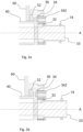
- Figs. 2a-2b show enlarged views of the planetary gear 30 and the clutch member 52.
- Fig. 2a represents the second state and fig 2b represents the first state.
- the clutch member 52 is movable between the first state and the second state in any direction along the rotational axis A of the propeller shaft 10.
- the clutch member 52 may be moved by use of an actuator (not shown), such as by an electromechanical, pneumatic or hydraulic actuator.
- the outer shaft 40 is arranged to rotate one full revolution or more than one full revolution with respect to the propeller shaft 10.
- the outer shaft 40 is freely rotatable with respect to the propeller shaft 10.
- the outer shaft 40 may be supported by bearings (not shown) provided in-between the propeller shaft 10 and the outer shaft 40.
- the bearings may be ball bearings or roller bearings.
- the propeller drive arrangement 1 may further comprise a first sensor 72 for measuring rotational speed of the outer shaft 40 and/or a second sensor 74 for measuring rotational speed of the propeller shaft 10.
- the propeller drive arrangement 1 may further comprise a control unit 76 arranged to receive signals from the first and second sensors 72, 74 which are indicative of rotational speeds of the outer shaft 40 and the propeller shaft 10.
- the control unit 76 is configured to output a signal, based on the received signals from the sensors 72, 74, which is indicative of a current pitch angle.
- the control unit 76 is an electronic control unit and may comprise hardware and/or software.
- the control unit 76 may be configured to update a value indicative of the current pitch angle every time a relative rotational speed of the outer shaft 40 and the propeller shaft 10 is registered.
- the updated value may be stored in a memory (not shown) associated with the control unit 76.
- the control unit 76 may receive signals from the sensors 72, 74 via a wireless connection and/or a wired connection.
- the control unit 76 may also be configured to issue control signals to the above-mentioned actuator for controlling the clutch member 52.
- the propeller drive arrangement 1 may further comprise a bevel gear arrangement 44 drivingly connecting the outer shaft 40 with the one or more propeller blades 22, 24. Accordingly, a rotational motion about the axis A of the outer shaft 40 relative to the propeller shaft 10 can be translated to rotational motions of the propeller blades 22, 24 with respect to the pitch angle rotational axes A2, A3.
- the propeller drive arrangement 1 preferably comprises only one planetary gear 30, thereby enabling a compact, low-weight and cost-effective configuration.
- Figs. 3 and 4a-b show an alternative embodiment of a propeller drive arrangement 1 according to the invention.
- the propeller drive arrangement 1 comprises:
- the propeller drive arrangement 1 further comprises a planetary gear 30.
- the planetary gear 30 comprises a first planetary gear member 36, a second planetary gear member 32 and a third planetary gear member 34 which are drivingly connected.
- the planetary gear 30 is coaxially arranged on the propeller shaft 10.
- the third planetary gear member is a planet carrier 34 of the planetary gear 30 carrying a plurality of planetary gear wheels 342.
- the second planetary gear member is a sun gear 32 of the planetary gear 30, and the first planetary gear member is a ring gear 36 of the planetary gear 30.
- the planetary gear wheels 342 are rotationally arranged on the planet carrier 34 and drivingly connect the sun gear 32 and the ring gear 36
- the propeller drive arrangement 1 further comprises an outer shaft 40' arranged coaxially with and radially outside of the propeller shaft 10.
- the outer shaft 40' is drivingly connected to the one or more propeller blades 22, 24 for varying the pitch angle.
- the propeller shaft 10, in one end 12 thereof, is configured to be drivingly connected to a propulsion unit (not shown) and, in a second end 14 thereof, is drivingly fixed to the propeller hub 20.
- the propeller shaft 10 is drivingly fixed to one of the planetary gear members, in this embodiment to the sun gear 32.
- Another one of the planetary gear members, in this embodiment the ring gear 36 is arranged to drive the outer shaft 40' by a driving torque exerted on the propeller shaft 10.
- the ring gear 36 may be integrated with the outer shaft 40'.
- the propeller drive arrangement 1 further comprises a pitch controlling member 52' for varying the pitch angle of the one or more propeller blades 22, 24.
- the pitch controlling member 52' is arranged to, in a first state, rotationally fix the third planetary gear member 34 to the second planetary gear member 32 so that the propeller shaft 10 and the outer shaft 40' are arranged to rotate with the same rotational speed, and, in a second state, engage the third planetary gear member 34 to a housing 60 so that the third planetary gear member 34 is rotationally fixed with respect to the housing 60. Accordingly, in the first state, the third planetary gear member, i.e. the planet carrier 34, is rotationally fixed to the propeller shaft 10.
- Figs. 4a-4b show enlarged views of the planetary gear 30 and the clutch member 52' as shown in fig. 3.
- Fig. 4a represents the second state and fig. 4b represents the first state.
- the clutch member 52' is movable between the first state and the second state in any direction along the rotational axis A of the propeller shaft 10.
- the clutch member 52' may be moved by use of an actuator (not shown), such as an electromechanical, pneumatic or hydraulic actuator.
- the propeller drive arrangement 1 may also as shown in fig. 3 comprise a bevel gear arrangement 44, sensors 72, 74 and a control unit 76.
- Fig. 5 depicts a side view of a vessel 100 according to an example embodiment of the invention.
- the vessel 100 is a marine vessel, and more particularly a sailing vessel comprising at least one sailing rig 110.
- the vessel 100 further comprises a propeller drive arrangement 1 according to an embodiment of the invention, such as the propeller drive arrangement 1 shown in fig. 1 or fig. 3 .
- the propeller drive arrangement 1 may be used for generating a propulsion force by a propulsion unit 120, such as an electric motor.
- the propeller drive arrangement 1 may also be used for regenerating power to an electric energy storage system (not shown), e.g. a battery, when the vessel 100 is using the sailing rig 110 for generating the propulsion force.
- an electric energy storage system not shown
- the regenerative power generation and/or the propulsion force can for example be optimized for improved energy efficiency.
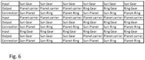
- Fig. 6 depicts a table with different connection possibilities of a propeller drive arrangement according to the invention.
- "Input” in the left column represents which member of the planetary gear that is drivingly fixed to the propeller shaft.
- Output in the left column represents which other member of the planetary gear that is arranged to drive the outer shaft.
- “Connection” in the left column represents which two members of the planetary gear that should be rotationally fixed to each other in the first state. As depicted from the table, a total of eighteen combinations are possible to achieve.
Landscapes
- Engineering & Computer Science (AREA)
- Chemical & Material Sciences (AREA)
- Combustion & Propulsion (AREA)
- Mechanical Engineering (AREA)
- Ocean & Marine Engineering (AREA)
- Aviation & Aerospace Engineering (AREA)
- Retarders (AREA)
Abstract
- a propeller shaft (10),
- a propeller hub (20) comprising one or more propeller blades (22, 24), wherein a pitch angle of the one or more propeller blades is variable,
- a planetary gear (30) comprising a first planetary gear member (32; 36), a second planetary gear member (34; 32) and a third planetary gear member (36; 34) which are drivingly connected, and
- an outer shaft (40) arranged coaxially with and radially outside of the propeller shaft (10), wherein the outer shaft (40) is drivingly connected to the one or more propeller blades (22, 24) for varying the pitch angle,
wherein the propeller shaft (10), in one end thereof (12), is configured to be drivingly connected to a propulsion unit and, in a second end (14) thereof, is drivingly fixed to the propeller hub (20),
and wherein the propeller shaft (10) is drivingly fixed to one of the planetary gear members (32) and wherein another one of the planetary gear members (34, 36) is arranged to drive the outer shaft (40) by a driving torque exerted on the propeller shaft (10), and
- the propeller drive arrangement (1) further comprising a pitch controlling member (52) for varying the pitch angle of the one or more propeller blades (22, 24),
wherein the pitch controlling member (52) is arranged to, in a first state, rotationally fix the third planetary gear member (36; 34) to the second planetary gear member (34; 32) so that the propeller shaft (10) and the outer shaft (40) are arranged to rotate with the same rotational speed, and, in a second state, engage the third planetary gear member (36; 34) to a housing (60) so that the third planetary gear member (36; 34) is rotationally fixed with respect to the housing (60). The invention also relates to a vessel (100).
Description
- The invention relates to a propeller drive arrangement. The invention also relates to a vessel comprising a propeller drive arrangement.
- The invention can be applied in marine vessels, such as in sailing vessels.
- A marine vessel may comprise a propeller drive arrangement with a propeller hub comprising one or more propeller blades. The pitch angle of the propeller blades may be adjustable.
- For example, it is known to equip a sailing vessel with a propeller drive arrangement comprising the above-mentioned propeller hub. The propeller drive arrangement may be driven by a motor, such as by an electric motor, which is powered by use of an electric energy storage system. For example, the energy storage system may be a battery, such as a lithium-ion battery.
- During sailing by the sailing vessel, power may be regenerated to the energy storage system, i.e. the electric motor may also function as an electric generator. For this purpose, the pitch angle(s) of the one or more propeller blades may be adjusted to optimize the regeneration of power, e.g. for improved energy efficiency.
- Additionally, or alternatively, it may also be advantageous to adjust the pitch angle when a propulsion force is generated by the propeller drive arrangement.
- In view of the above, there is a strive to develop a reliable, robust, compact, efficient and/or cost-effective propeller drive arrangement with adjustable propeller blade pitch angle(s).
- An object of the invention is to provide an improved propeller drive arrangement which alleviates at least one drawback of the prior art, or which at least provides a suitable alternative. Another object of the invention is to provide an improved vessel, such as a sailing vessel, which alleviates at least one drawback of the prior art, or which at least provides a suitable alternative.
- According to a first aspect of the invention, the object is achieved by a propeller drive arrangement according to
claim 1. - Thus, there is provided a propeller drive arrangement, comprising:
- a propeller shaft,
- a propeller hub comprising one or more propeller blades, wherein a pitch angle of the one or more propeller blades is variable,
- a planetary gear comprising a first planetary gear member, a second planetary gear member and a third planetary gear member which are drivingly connected, and
- an outer shaft arranged coaxially with and radially outside of the propeller shaft, wherein the outer shaft is drivingly connected to the one or more propeller blades for varying the pitch angle,
- wherein the propeller shaft, in one end thereof, is configured to be drivingly connected to a propulsion unit and, in a second end thereof, is drivingly fixed to the propeller hub,
- and wherein the propeller shaft is drivingly fixed to one of the planetary gear members and wherein another one of the planetary gear members is arranged to drive the outer shaft by a driving torque exerted on the propeller shaft, and
- the propeller drive arrangement further comprising a pitch controlling member for varying the pitch angle of the one or more propeller blades,
- By the provision of the propeller drive arrangement as disclosed herein, an improved propeller drive arrangement is achieved. For example, the present invention is based on a realization that the pitch angle can be efficiently controlled by use of a pitch controlling member and by only one planetary gear which is drivingly connected to the one or more propeller blades for varying the pitch angle. Thereby, a compact configuration is achieved, implying e.g. a reduced need of adding further gears for achieving the function of the propeller drive arrangement. This also implies a more reliable and robust configuration since few components are required for the pitch angle function of the propeller drive arrangement.
- By controlling the pitch angle by the pitch controlling member as disclosed herein is meant to vary, or adjust, the pitch angle of the one or more propeller blades, and also to maintain the one or more propeller blades at a fixed pitch angle. The pitch angle of each propeller blade is adjusted with respect to a respective pitch angle rotational axis of the respective propeller blade. The pitch angle rotational axis of each propeller blade preferably extends along a radial direction of the propeller shaft.
- When the propeller shaft and the outer shaft rotate with the same rotational speed, the pitch angle of the one or more propeller blades is fixed. In addition, when the third planetary gear member is rotationally fixed with respect to the housing, the pitch angle of the one or more propeller blades is adjusted when also the propeller shaft is rotating.
- Each one of the first, second and third planetary gear members of the planetary gear is a respective one of a sun gear, a planet carrier carrying a plurality of planetary gear wheels, and a ring gear. Accordingly, by way of example, several different combinations are feasible for achieving the variable pitch angle function as disclosed herein. More specifically, it has been realized that six different input/output configurations are feasible, i.e. six different combinations with different connections to the propeller shaft and the outer shaft. By way of example, if the propeller shaft is drivingly fixed to the sun gear, either the planet carrier or the ring gear can be arranged to drive the outer shaft by a driving torque exerted on the propeller shaft. In addition, by varying which two members of the planetary gear member that should be rotationally fixed to each other in the first state, a total of three combinations are possible for each input/output configuration. This results in a total of eighteen possible combinations.
- Optionally, the first planetary gear member is drivingly fixed to the propeller shaft. Still optionally, the sun gear is drivingly fixed to the propeller shaft.
- Optionally, the first planetary gear member is a sun gear of the planetary gear. This implies a simplified configuration where the sun gear, which is closest to a rotational axis of the planetary gear, may be drivingly fixed to the propeller shaft.
- Still optionally, the second planetary gear member is a planet carrier of the planetary gear carrying a plurality of planetary gear wheels. The planetary gear wheels are rotationally arranged on the planet carrier and drivingly connect the sun gear and the ring gear. This also implies a simplified configuration. For example, the planet carrier may be drivingly fixed to the outer shaft.
- Still optionally, the third planetary gear member is a ring gear of the planetary gear.
- Optionally, the third planetary gear member is a planet carrier of the planetary gear carrying a plurality of planetary gear wheels. The planetary gear wheels are rotationally arranged on the planet carrier and drivingly connect the sun gear and the ring gear.
- Still optionally, the second planetary gear member is a sun gear of the planetary gear.
- Still optionally, the first planetary gear member is a ring gear of the planetary gear. The ring gear may be drivingly fixed to the outer shaft.
- Optionally, the pitch controlling member is a clutch member. By way of example, the clutch member may be a friction clutch member or a dog clutch member.
- Optionally, the clutch member is movable between the first state and the second state in any direction corresponding to a direction of a rotational axis of the propeller shaft. Accordingly, the clutch member may be movable back and forth along the rotational axis of the propeller shaft. The clutch member may enclose the propeller shaft, e.g. be coaxial with the propeller shaft, as seen in a plane being perpendicular to the rotational axis of the propeller shaft.
- Optionally, the outer shaft is arranged to rotate one full revolution or more than one full revolution with respect to the propeller shaft. Thereby, the pitch angle of the one or more propeller blades may be set to any angle, i.e. an angle of 0 to 360 degrees with respect to a pitch angle rotational axis of the respective propeller blade.
- Optionally, the propeller drive arrangement further comprises a first sensor for measuring rotational speed of the outer shaft and/or a second sensor for measuring rotational speed of the propeller shaft. Thereby, the pitch angle can be controlled in a reliable and predictive manner. Still optionally, the propeller drive arrangement further comprises a control unit arranged to receive signals from the first and second sensors which are indicative of rotational speeds of the propeller shaft and the outer shaft, wherein the control unit is configured to output a signal, based on the received signals from the sensors, which is indicative of a current pitch angle. The control unit may be configured to update a value indicative of the current pitch angle every time a relative rotational speed of the outer shaft and the propeller shaft is registered. The updated value may be stored in a memory associated with the control unit. As such, the current pitch angle is always known for a user.
- Optionally, the propeller drive arrangement further comprises a bevel gear arrangement drivingly connecting the outer shaft with the one or more propeller blades.
- Optionally, the propeller drive arrangement comprises only one planetary gear. This implies a compact configuration.
- According to a second aspect of the invention, the object is achieved by a vessel according to claim 15. Thus, there is provided a vessel, such as a sailing vessel, comprising a propeller drive arrangement according to any one of the embodiments of the first aspect of the invention.
- Advantages and effects of the second aspect of the invention are analogous to the advantages and effects of the first aspect of the invention.
- Further advantages and advantageous features of the invention are disclosed in the following description and in the dependent claims.
- With reference to the appended drawings, below follows a more detailed description of embodiments of the invention cited as examples.
- In the drawings:
-
Fig. 1 is a sectional view of a propeller drive arrangement according to an example embodiment of the present invention, -
Figs. 2a-b are enlarged sectional views of the propeller drive arrangement as shown infig. 1 , -
Fig. 3 is a sectional view of a propeller drive arrangement according to another example embodiment of the present invention, -
Figs. 4a-b are enlarged sectional views of the propeller drive arrangement as shown infig. 3 , -
Fig. 5 is a side view of a vessel according to an example embodiment of the present invention, and -
Fig. 6 shows a table with different connection possibilities of a propeller drive arrangement according to the present invention. - The drawings are schematic and not necessarily drawn to scale. It shall be understood that the embodiments shown and described are exemplifying and that the disclosure is not limited to these embodiments. It shall also be noted that some details in the drawings may be exaggerated in order to better describe and illustrate the disclosure. Like reference characters throughout the drawings refer to the same, or similar, type of element unless expressed otherwise.
-
Fig. 1 depicts a sectional view of apropeller drive arrangement 1 according to an example embodiment of the present invention. Thepropeller drive arrangement 1 comprises apropeller shaft 10. The sectional view is a plane including a rotational axis A of thepropeller shaft 10. - The
propeller drive arrangement 1 comprises: - the
propeller shaft 10, and - a
propeller hub 20 comprising one ormore propeller blades more propeller blades - The
propeller drive arrangement 1 further comprises aplanetary gear 30. Theplanetary gear 30 comprises a firstplanetary gear member 32, a secondplanetary gear member 34 and a thirdplanetary gear member 36 which are drivingly connected. Theplanetary gear 30 is coaxially arranged on thepropeller shaft 10. - In the shown embodiment, the first
planetary gear member 32 is asun gear 32, the secondplanetary gear member 34 is aplanet carrier 34 carrying a plurality ofplanetary gear wheels 342, and the thirdplanetary gear member 36 isring gear 36. Theplanetary gear wheels 342 are rotationally arranged on theplanet carrier 34 and drivingly connect thesun gear 32 and thering gear 36. - The
propeller drive arrangement 1 further comprises anouter shaft 40 arranged coaxially with and radially outside of thepropeller shaft 10. Theouter shaft 40 is drivingly connected to the one ormore propeller blades - The
propeller shaft 10, in oneend 12 thereof, is configured to be drivingly connected to a propulsion unit (not shown) and, in asecond end 14 thereof, is drivingly fixed to thepropeller hub 20. - The
propeller shaft 10 is drivingly fixed to one of the planetary gear members, in this embodiment to thesun gear 32. Another one of the planetary gear members, in this embodiment theplanet carrier 34, is arranged to drive theouter shaft 40 by a driving torque exerted on thepropeller shaft 10. As shown infig. 1 theplanet carrier 34 may be integrated with theouter shaft 40. - The
propeller drive arrangement 1 further comprises apitch controlling member 52 for varying the pitch angle of the one ormore propeller blades - The
pitch controlling member 52 is arranged to, in a first state, rotationally fix the thirdplanetary gear member 36 to the secondplanetary gear member 34 so that thepropeller shaft 10 and theouter shaft 40 are arranged to rotate with the same rotational speed, and, in a second state, engage the thirdplanetary gear member 36 to ahousing 60 so that the thirdplanetary gear member 36 is rotationally fixed with respect to thehousing 60. - When the
propeller shaft 10 and theouter shaft 40 rotate with the same rotational speed, the pitch angle of the one ormore propeller blades planetary gear member 36 is rotationally fixed with respect to thehousing 60, the pitch angle of the one ormore propeller blades propeller shaft 10 is rotating. Accordingly, the pitch angle is adjusted when thepropeller shaft 10 and theouter shaft 40 rotate relative each other. - The pitch angle of each
propeller blade respective propeller blade propeller blade propeller shaft 10. - The
pitch controlling member 52 may as shown infig. 1 be a clutch member, such as a friction clutch member or a dog clutch member. -
Figs. 2a-2b show enlarged views of theplanetary gear 30 and theclutch member 52.Fig. 2a represents the second state andfig 2b represents the first state. Theclutch member 52 is movable between the first state and the second state in any direction along the rotational axis A of thepropeller shaft 10. Theclutch member 52 may be moved by use of an actuator (not shown), such as by an electromechanical, pneumatic or hydraulic actuator. - Furthermore, in the shown embodiment, the
outer shaft 40 is arranged to rotate one full revolution or more than one full revolution with respect to thepropeller shaft 10. In other words, in the shown embodiment, theouter shaft 40 is freely rotatable with respect to thepropeller shaft 10. Theouter shaft 40 may be supported by bearings (not shown) provided in-between thepropeller shaft 10 and theouter shaft 40. The bearings may be ball bearings or roller bearings. - As further shown in
fig. 1 , thepropeller drive arrangement 1 may further comprise afirst sensor 72 for measuring rotational speed of theouter shaft 40 and/or asecond sensor 74 for measuring rotational speed of thepropeller shaft 10. Thepropeller drive arrangement 1 may further comprise acontrol unit 76 arranged to receive signals from the first andsecond sensors outer shaft 40 and thepropeller shaft 10. Thecontrol unit 76 is configured to output a signal, based on the received signals from thesensors - The
control unit 76 is an electronic control unit and may comprise hardware and/or software. Thecontrol unit 76 may be configured to update a value indicative of the current pitch angle every time a relative rotational speed of theouter shaft 40 and thepropeller shaft 10 is registered. The updated value may be stored in a memory (not shown) associated with thecontrol unit 76. As such, the current pitch angle is always known for a user. Thecontrol unit 76 may receive signals from thesensors control unit 76 may also be configured to issue control signals to the above-mentioned actuator for controlling theclutch member 52. - As shown in
fig. 1 , thepropeller drive arrangement 1 may further comprise abevel gear arrangement 44 drivingly connecting theouter shaft 40 with the one ormore propeller blades outer shaft 40 relative to thepropeller shaft 10 can be translated to rotational motions of thepropeller blades - As further depicted in
fig. 1 , thepropeller drive arrangement 1 preferably comprises only oneplanetary gear 30, thereby enabling a compact, low-weight and cost-effective configuration. -
Figs. 3 and4a-b show an alternative embodiment of apropeller drive arrangement 1 according to the invention. - The
propeller drive arrangement 1 comprises: - the
propeller shaft 10, and - a
propeller hub 20 comprising one ormore propeller blades more propeller blades - The
propeller drive arrangement 1 further comprises aplanetary gear 30. Theplanetary gear 30 comprises a firstplanetary gear member 36, a secondplanetary gear member 32 and a thirdplanetary gear member 34 which are drivingly connected. Theplanetary gear 30 is coaxially arranged on thepropeller shaft 10. - Accordingly, in this embodiment, the third planetary gear member is a
planet carrier 34 of theplanetary gear 30 carrying a plurality ofplanetary gear wheels 342. The second planetary gear member is asun gear 32 of theplanetary gear 30, and the first planetary gear member is aring gear 36 of theplanetary gear 30. Theplanetary gear wheels 342 are rotationally arranged on theplanet carrier 34 and drivingly connect thesun gear 32 and thering gear 36 - The
propeller drive arrangement 1 further comprises an outer shaft 40' arranged coaxially with and radially outside of thepropeller shaft 10. The outer shaft 40' is drivingly connected to the one ormore propeller blades - The
propeller shaft 10, in oneend 12 thereof, is configured to be drivingly connected to a propulsion unit (not shown) and, in asecond end 14 thereof, is drivingly fixed to thepropeller hub 20. - The
propeller shaft 10 is drivingly fixed to one of the planetary gear members, in this embodiment to thesun gear 32. Another one of the planetary gear members, in this embodiment thering gear 36, is arranged to drive the outer shaft 40' by a driving torque exerted on thepropeller shaft 10. As shown infig. 3 , thering gear 36 may be integrated with the outer shaft 40'. - The
propeller drive arrangement 1 further comprises a pitch controlling member 52' for varying the pitch angle of the one ormore propeller blades - The pitch controlling member 52' is arranged to, in a first state, rotationally fix the third
planetary gear member 34 to the secondplanetary gear member 32 so that thepropeller shaft 10 and the outer shaft 40' are arranged to rotate with the same rotational speed, and, in a second state, engage the thirdplanetary gear member 34 to ahousing 60 so that the thirdplanetary gear member 34 is rotationally fixed with respect to thehousing 60. Accordingly, in the first state, the third planetary gear member, i.e. theplanet carrier 34, is rotationally fixed to thepropeller shaft 10. -
Figs. 4a-4b show enlarged views of theplanetary gear 30 and the clutch member 52' as shown infig. 3. Fig. 4a represents the second state andfig. 4b represents the first state. The clutch member 52' is movable between the first state and the second state in any direction along the rotational axis A of thepropeller shaft 10. The clutch member 52' may be moved by use of an actuator (not shown), such as an electromechanical, pneumatic or hydraulic actuator. - In similar with the above embodiment shown in
fig. 1 , thepropeller drive arrangement 1 may also as shown infig. 3 comprise abevel gear arrangement 44,sensors control unit 76. -
Fig. 5 depicts a side view of avessel 100 according to an example embodiment of the invention. Thevessel 100 is a marine vessel, and more particularly a sailing vessel comprising at least onesailing rig 110. Thevessel 100 further comprises apropeller drive arrangement 1 according to an embodiment of the invention, such as thepropeller drive arrangement 1 shown infig. 1 orfig. 3 . Thepropeller drive arrangement 1 may be used for generating a propulsion force by apropulsion unit 120, such as an electric motor. Thepropeller drive arrangement 1 may also be used for regenerating power to an electric energy storage system (not shown), e.g. a battery, when thevessel 100 is using thesailing rig 110 for generating the propulsion force. By varying the pitch angle during use of thevessel 100, the regenerative power generation and/or the propulsion force can for example be optimized for improved energy efficiency. -
Fig. 6 depicts a table with different connection possibilities of a propeller drive arrangement according to the invention. "Input" in the left column represents which member of the planetary gear that is drivingly fixed to the propeller shaft. "Output" in the left column represents which other member of the planetary gear that is arranged to drive the outer shaft. "Connection" in the left column represents which two members of the planetary gear that should be rotationally fixed to each other in the first state. As depicted from the table, a total of eighteen combinations are possible to achieve. - It is to be understood that the present invention is not limited to the embodiments described above and illustrated in the drawings; rather, the skilled person will recognize that many changes and modifications may be made within the scope of the appended claims.
Claims (15)
- A propeller drive arrangement (1), comprising:- a propeller shaft (10),- a propeller hub (20) comprising one or more propeller blades (22, 24), wherein a pitch angle of the one or more propeller blades is variable,- a planetary gear (30) comprising a first planetary gear member (32; 36), a second planetary gear member (34; 32) and a third planetary gear member (36; 34) which are drivingly connected, and- an outer shaft (40) arranged coaxially with and radially outside of the propeller shaft (10), wherein the outer shaft (40) is drivingly connected to the one or more propeller blades (22, 24) for varying the pitch angle,wherein the propeller shaft (10), in one end thereof (12), is configured to be drivingly connected to a propulsion unit and, in a second end (14) thereof, is drivingly fixed to the propeller hub (20),and wherein the propeller shaft (10) is drivingly fixed to one of the planetary gear members (32) and wherein another one of the planetary gear members (34, 36) is arranged to drive the outer shaft (40) by a driving torque exerted on the propeller shaft (10), and- the propeller drive arrangement (1) further comprising a pitch controlling member (52) for varying the pitch angle of the one or more propeller blades (22, 24),wherein the pitch controlling member (52) is arranged to, in a first state, rotationally fix the third planetary gear member (36; 34) to the second planetary gear member (34; 32) so that the propeller shaft (10) and the outer shaft (40) are arranged to rotate with the same rotational speed, and, in a second state, engage the third planetary gear member (36; 34) to a housing (60) so that the third planetary gear member (36; 34) is rotationally fixed with respect to the housing (60).
- The propeller drive arrangement (1) according to claim 1, wherein the first planetary gear member is a sun gear (32) of the planetary gear (30).
- The propeller drive arrangement (1) according to any one of the preceding claims, wherein the second planetary gear member is a planet gear carrier (34) of the planetary gear (30) carrying a plurality of planetary gear wheels (342).
- The propeller drive arrangement (1) according to any one of the preceding claims, wherein the third planetary gear member is a ring gear (36) of the planetary gear (30).
- The propeller drive arrangement (1) according to claim 1, wherein the third planetary gear member is a planet carrier (34) of the planetary gear (30) carrying a plurality of planetary gear wheels (342).
- The propeller drive arrangement (1) according to claim 5, wherein the second planetary gear member is a sun gear (32) of the planetary gear (30).
- The propeller drive arrangement (1) according to claim 6, wherein the first planetary gear member is a ring gear (36) of the planetary gear (30).
- The propeller drive arrangement (1) according to any one of the preceding claims, wherein the pitch controlling member is a clutch member (52).
- The propeller drive arrangement (1) according to claim 8, wherein the clutch member (52) is movable between the first state and the second state in any direction (A) corresponding to a direction of a rotational axis (A) of the propeller shaft (10).
- The propeller drive arrangement (1) according to any one of the preceding claims, wherein the outer shaft (40) is arranged to rotate one full revolution or more than one full revolution with respect to the propeller shaft (10).
- The propeller drive arrangement (1) according to any one of the preceding claims, further comprising a first sensor (72) for measuring rotational speed of the outer shaft (40) and/or a second sensor (74) for measuring rotational speed of the propeller shaft (10).
- The propeller drive arrangement (1) according to claim 11, further comprising a control unit (76) arranged to receive signals from the first and second sensors (72, 74) which are indicative of rotational speeds of the propeller shaft and the outer shaft (40), wherein the control unit is configured to output a signal, based on the received signals from the sensors, which is indicative of a current pitch angle.
- The propeller drive arrangement (1) according to any one of the preceding claims, further comprising a bevel gear arrangement (44) drivingly connecting the outer shaft (40) with the one or more propeller blades (22, 24).
- The propeller drive arrangement (1) according to any one of the preceding claims, wherein the propeller drive arrangement (1) comprises only one planetary gear (30).
- A vessel (100), such as a sailing vessel, comprising a propeller drive arrangement (1) according to any one of the preceding claims.
Priority Applications (3)
| Application Number | Priority Date | Filing Date | Title |
|---|---|---|---|
| EP22183377.5A EP4303113A1 (en) | 2022-07-06 | 2022-07-06 | A propeller drive arrangement |
| CN202310599630.4A CN117360742A (en) | 2022-07-06 | 2023-05-25 | propeller drive arrangement |
| US18/343,253 US20240010315A1 (en) | 2022-07-06 | 2023-06-28 | Propeller drive arrangement |
Applications Claiming Priority (1)
| Application Number | Priority Date | Filing Date | Title |
|---|---|---|---|
| EP22183377.5A EP4303113A1 (en) | 2022-07-06 | 2022-07-06 | A propeller drive arrangement |
Publications (1)
| Publication Number | Publication Date |
|---|---|
| EP4303113A1 true EP4303113A1 (en) | 2024-01-10 |
Family
ID=82399426
Family Applications (1)
| Application Number | Title | Priority Date | Filing Date |
|---|---|---|---|
| EP22183377.5A Withdrawn EP4303113A1 (en) | 2022-07-06 | 2022-07-06 | A propeller drive arrangement |
Country Status (3)
| Country | Link |
|---|---|
| US (1) | US20240010315A1 (en) |
| EP (1) | EP4303113A1 (en) |
| CN (1) | CN117360742A (en) |
Families Citing this family (1)
| Publication number | Priority date | Publication date | Assignee | Title |
|---|---|---|---|---|
| EP4722098A1 (en) * | 2024-10-07 | 2026-04-08 | Volvo Penta Corporation | A marine propulsion unit |
Citations (3)
| Publication number | Priority date | Publication date | Assignee | Title |
|---|---|---|---|---|
| GB569056A (en) * | 1944-06-10 | 1945-05-02 | Percy Octavius Rowlands | Improvements in marine screw propellers of the variable pitch and reversing type |
| US20040157509A1 (en) * | 1998-06-25 | 2004-08-12 | Aimbridge Pty. Ltd. | Motor for driving a propeller including a phase adjuster |
| JP2020015347A (en) * | 2018-07-23 | 2020-01-30 | 株式会社Ihi原動機 | Blade angle changing device for variable pitch propeller and gyration type vessel propulsion device |
Family Cites Families (2)
| Publication number | Priority date | Publication date | Assignee | Title |
|---|---|---|---|---|
| US5451141A (en) * | 1993-12-23 | 1995-09-19 | United Technologies Corporation | Propeller pitch change machanism with inductive brake and motor |
| US8740565B2 (en) * | 2011-08-12 | 2014-06-03 | Hamilton Sundstrand Corporation | Modular counter rotating propeller system |
-
2022
- 2022-07-06 EP EP22183377.5A patent/EP4303113A1/en not_active Withdrawn
-
2023
- 2023-05-25 CN CN202310599630.4A patent/CN117360742A/en active Pending
- 2023-06-28 US US18/343,253 patent/US20240010315A1/en not_active Abandoned
Patent Citations (3)
| Publication number | Priority date | Publication date | Assignee | Title |
|---|---|---|---|---|
| GB569056A (en) * | 1944-06-10 | 1945-05-02 | Percy Octavius Rowlands | Improvements in marine screw propellers of the variable pitch and reversing type |
| US20040157509A1 (en) * | 1998-06-25 | 2004-08-12 | Aimbridge Pty. Ltd. | Motor for driving a propeller including a phase adjuster |
| JP2020015347A (en) * | 2018-07-23 | 2020-01-30 | 株式会社Ihi原動機 | Blade angle changing device for variable pitch propeller and gyration type vessel propulsion device |
Also Published As
| Publication number | Publication date |
|---|---|
| US20240010315A1 (en) | 2024-01-11 |
| CN117360742A (en) | 2024-01-09 |
Similar Documents
| Publication | Publication Date | Title |
|---|---|---|
| US20240010316A1 (en) | Propeller drive arrangement | |
| JP5107987B2 (en) | Marine propulsion device | |
| KR100187697B1 (en) | Combination of motor and power train with dual input means to achieve continuous output speed | |
| EP3904200B1 (en) | Method and apparatus in an electric propulsion arrangement of a sailing vessel | |
| JP4445089B2 (en) | Ship propulsion device | |
| US5851162A (en) | System and apparatus for a multiple input and dual output electric differential motor transmission device | |
| JP2001289149A (en) | Yaw turning drive for wind power generator and yaw turning drive control method for wind power generator | |
| CN107054597A (en) | A kind of new coaxial incorgruous twin screw device and its implementation | |
| US20240010315A1 (en) | Propeller drive arrangement | |
| KR101261867B1 (en) | Pod type propulsion device and ship with the same | |
| WO2011013751A1 (en) | Swiveling propeller device | |
| JP2012517937A (en) | CONTROL DEVICE AND BOAT DRIVE DEVICE PROVIDED WITH CONTROL DEVICE | |
| JP2009516993A (en) | Multi-input, dual-output electric differential motor transmission system | |
| RU2583125C1 (en) | Marine propulsion installation | |
| JP2008008422A (en) | Power transmission and working machine | |
| EP2306048B1 (en) | Electric drive system | |
| JP3381865B2 (en) | Fluid energy conversion device, rotational energy conversion device and ship using them | |
| CN203005734U (en) | Telex steering control system | |
| KR102895034B1 (en) | Power drive apparatus for hybrid propulsion of ship | |
| FI131952B1 (en) | Device for regulating the propeller blade angle in an electric propulsion system | |
| CN112713745A (en) | Kinetic energy power generation device | |
| EP4594175A1 (en) | Propeller system for a boat and boat including the same | |
| CN114426090A (en) | Propeller and underwater vehicle using same | |
| JPH01226489A (en) | Submersible propulsion system | |
| RU2521172C2 (en) | Marine propulsive arrangement with power accumulator |
Legal Events
| Date | Code | Title | Description |
|---|---|---|---|
| PUAI | Public reference made under article 153(3) epc to a published international application that has entered the european phase |
Free format text: ORIGINAL CODE: 0009012 |
|
| STAA | Information on the status of an ep patent application or granted ep patent |
Free format text: STATUS: THE APPLICATION HAS BEEN PUBLISHED |
|
| AK | Designated contracting states |
Kind code of ref document: A1 Designated state(s): AL AT BE BG CH CY CZ DE DK EE ES FI FR GB GR HR HU IE IS IT LI LT LU LV MC MK MT NL NO PL PT RO RS SE SI SK SM TR |
|
| STAA | Information on the status of an ep patent application or granted ep patent |
Free format text: STATUS: REQUEST FOR EXAMINATION WAS MADE |
|
| 17P | Request for examination filed |
Effective date: 20240701 |
|
| RBV | Designated contracting states (corrected) |
Designated state(s): AL AT BE BG CH CY CZ DE DK EE ES FI FR GB GR HR HU IE IS IT LI LT LU LV MC MK MT NL NO PL PT RO RS SE SI SK SM TR |
|
| GRAP | Despatch of communication of intention to grant a patent |
Free format text: ORIGINAL CODE: EPIDOSNIGR1 |
|
| STAA | Information on the status of an ep patent application or granted ep patent |
Free format text: STATUS: GRANT OF PATENT IS INTENDED |
|
| INTG | Intention to grant announced |
Effective date: 20240904 |
|
| STAA | Information on the status of an ep patent application or granted ep patent |
Free format text: STATUS: THE APPLICATION IS DEEMED TO BE WITHDRAWN |
|
| 18D | Application deemed to be withdrawn |
Effective date: 20250108 |